AIR CONDITIONING
A/C Wiring Diagram for Toyota Celica ST 1997

List of elements for A/C Wiring Diagram for Toyota Celica ST 1997:
- (a/c harness, at right kick panel)
- (engine rm harn, right side of engine compt)
- (engine room harn, front center of engine compt)
- (engine room harn, left rear corner of engine compt)
- (left front of engine compt)
- (right front of engine compt)
- (right kick panel)
- 1.8l
- 1994 vftc c
- 2.2l only
- A/c
- A/c amplifier (right side of i/p)
- A/c condenser fan motor
- A/c dual pressure switch (left front of engine compt)
- A/c fuse 10a
- A/c high pressure switch (left front of engine compt)
- A/c magnetic clutch & lock sensor (right front of engine)
- A/c magnetic clutch relay
- A/c thermistor (right side of i/p)
- A/c+
- Ac1
- Ac1 aca
- Acid
- Act
- Air inlet control servo motor (right side of i/p)
- Air vent mode control servo motor (center of i/p)
- B/l
- Blower motor (right side of i/p)
- Blower resistor (right side of i/p)
- Blower switch
- Case grounded for 1.8l
- Cds fan fusible link 30a
- Control circuit
- Control switch
- Def
- Ecu-ig fuse 15a
- Engine control module (right side of i/p)
- Face
- Fan relay no. 2
- Fan relay no. 3
- Fid
- Foot
- Frs
- G101 (right front fender)
- G203 (r/b 4 set bolt)
- G203 (r/b 4 set bolt) j/c 9 (right kick panel)
- Gnd
- Heater control switch
- Heater fuse 40a
- Heater relay
- Hot at all times
- Hot in run or start
- Htr fuse 10a
- I11 (cowl harn, center of i/p)
- I16
- Ig+
- Ign
- Igniter (left rear of engine compt)
- Ill+
- Ill-
- Interior lights system
- J/b 1 (left side of i/p)
- J/c 5 (right side of i/p)
- J/c 6 (behind right side of i/p)
- J/c 9
- Led
- Lock
- Mgc
- Prs
- R/b 2 (left side engine compt)
- R/b 2 (left side of engine compt)
- R/b 4
- R/b 4 (right kick panel)
- R/b 5 (right front of engine compt)
- Radiator fan motor
- Radiator fan relay no. 1
- Rdi fan fusible link 30a
- Rec
- Red
- Water temperature switch (right radiator support)
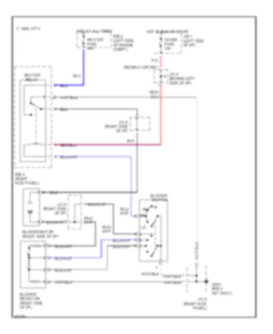
Heater Wiring Diagram for Toyota Celica ST 1997
List of elements for Heater Wiring Diagram for Toyota Celica ST 1997:
- Blower motor (right side of i/p)
- Blower resistor (right side of i/p)
- Blower switch
- C 1995 vftc
- F13
- G203 (r/b 4 set bolt)
- Gauge fuse 10a
- Heater fuse 40a
- Heater relay
- Hot at all times
- Hot in run or start
- J/b 1 (left side of i/p)
- J/c 5 (right side of i/p)
- J/c 6 (behind left side of i/p)
- J/c 9 (right kick panel)
- R/b 2 (left side of engine compt)
- R/b 4 (right kick panel)
 English