AIR CONDITIONING
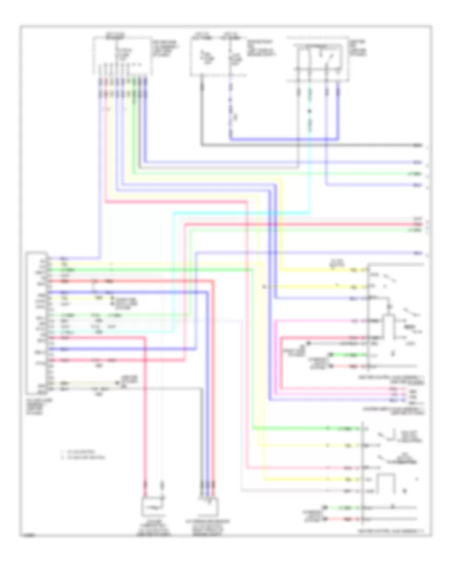
Automatic A/C Wiring Diagram (1 of 2) for Toyota Corolla LE Eco Plus 2014

List of elements for Automatic A/C Wiring Diagram (1 of 2) for Toyota Corolla LE Eco Plus 2014:
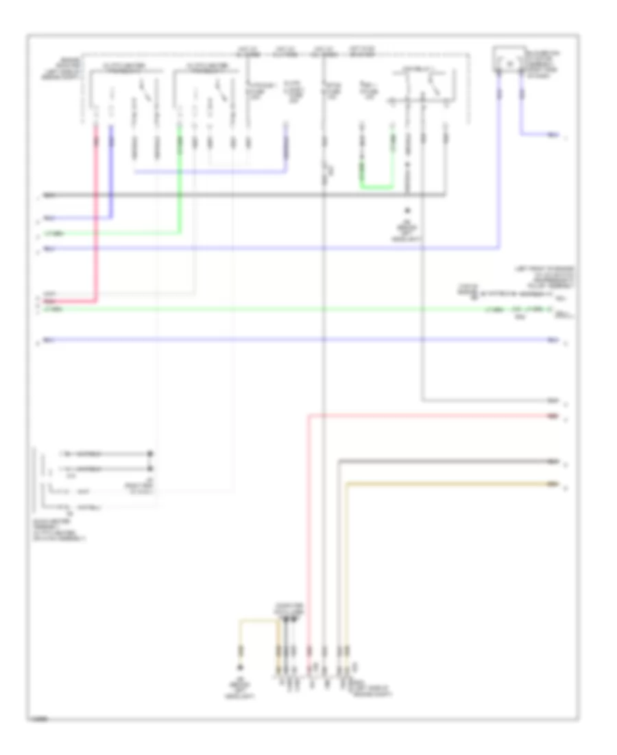
Automatic A/C Wiring Diagram (2 of 2) for Toyota Corolla LE Eco Plus 2014
List of elements for Automatic A/C Wiring Diagram (2 of 2) for Toyota Corolla LE Eco Plus 2014:
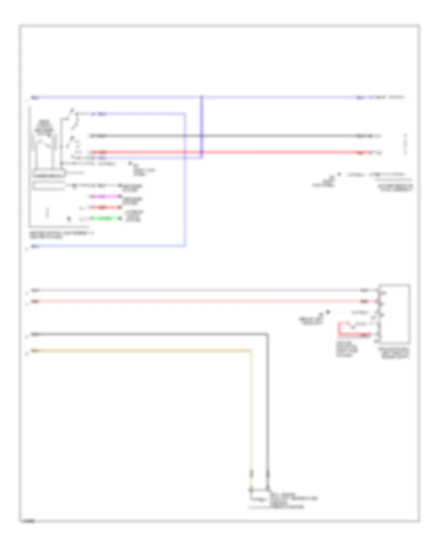
Manual A/C Wiring Diagram (1 of 3) for Toyota Corolla LE Eco Plus 2014
List of elements for Manual A/C Wiring Diagram (1 of 3) for Toyota Corolla LE Eco Plus 2014:
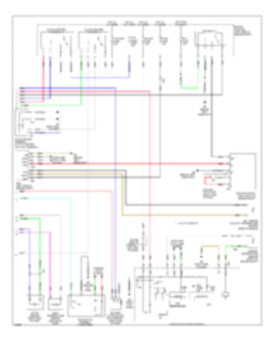
Manual A/C Wiring Diagram (2 of 3) for Toyota Corolla LE Eco Plus 2014
List of elements for Manual A/C Wiring Diagram (2 of 3) for Toyota Corolla LE Eco Plus 2014:
Manual A/C Wiring Diagram (3 of 3) for Toyota Corolla LE Eco Plus 2014
List of elements for Manual A/C Wiring Diagram (3 of 3) for Toyota Corolla LE Eco Plus 2014: