AIR CONDITIONING
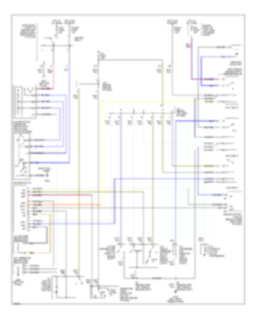
Heater Wiring Diagram for Toyota ECHO 2001

List of elements for Heater Wiring Diagram for Toyota ECHO 2001:
- A/c fuse 7.5a
- Air inlet control servo motor (upper right side of dash, on hvac housing)
- Alt
- Blower motor & resistor (behind right side of dash, in hvac housing)
- Blower switch
- Ecu-ig fuse 7.5a
- Els
- Engine control module (behind lower right side of dash)
- Engine room j/b (left side of engine compt)
- Engine room r/b (left side of engine compt)
- F/d
- Foot
- Foot mode
- Frs
- G10
- G200
- G200 (left kick panel)
- G203 (right kick panel)
- Gauge fuse 10a
- Generator
- Gnd
- H11
- Heater relay
- Heater sub 1 relay
- Hot at all times
- Hot in on or start
- Htr fuse 40a
- Htr fuse 50a
- Inlet air position detection switch
- Instrument panel j/b (behind left side of dash, near base of "a" pillar)
- J/c 2 (behind left side of dash)
- J/c 5 (behind left kick panel)
- J/c 9 (behind right kick panel)
- Max hot
- Max hot & foot mode switch
- Mhsw
- Mode in
- Off
- Ptc amplifier (behind upper right side of dash)
- Ptc heater (behind left center of dash)
- Ptc1
- R/f1
- Rec
- Rec/frs
- Red
- Taco
- Tw1
- Water temperature sensor (behind upper right side of dash)
Manual A/C Wiring Diagram for Toyota ECHO 2001
List of elements for Manual A/C Wiring Diagram for Toyota ECHO 2001:
- (left side of engine compt) engine room j/b
- (right kick panel)
- A/c
- A/c magnetic clutch (on a/c compressor)
- A/c amplifier (behind right side of dash)
- A/c condenser fan resistor (left side of engine compt)
- A/c fuse 7.5a
- A/c switch (part of center cluster switch)
- A/c thermistor (behind right side of dash)
- A/c triple pressure switch (right side of engine compt)
- A10
- Act
- Blower motor & resistor (behind right side of dash, in hvac housing)
- Blower switch
- Cfn+
- Cfn-
- Def
- Defroster mode detection switch (behind center of dash)
- Dual
- E4 (engine harn, left side of engine compt)
- Ecu-ig fuse 7.5a
- Engine control module (behind lower right side of dash)
- Engine room j/b (left side of engine compt)
- Fan 1 relay
- Fan 2 relay
- Foot & def
- G100 (left front fender apron)
- G200 (left kick panel)
- G203
- Gauge fuse 10a
- Gnd
- H18
- Heater relay
- Hot at all times
- Hot in on or start
- Htr fuse 40a
- Instrument panel j/b (behind left side of dash, near base of "a" pillar)
- J/c 1 (behind left side of dash)
- J/c 8 (behind center of dash)
- Mg/c relay
- Mgc
- Off
- Prs
- Radiator fan motor
- Rdi fuse 30a
- Single
- Water temperature switch (front of engine compt)
 English