AIR CONDITIONING
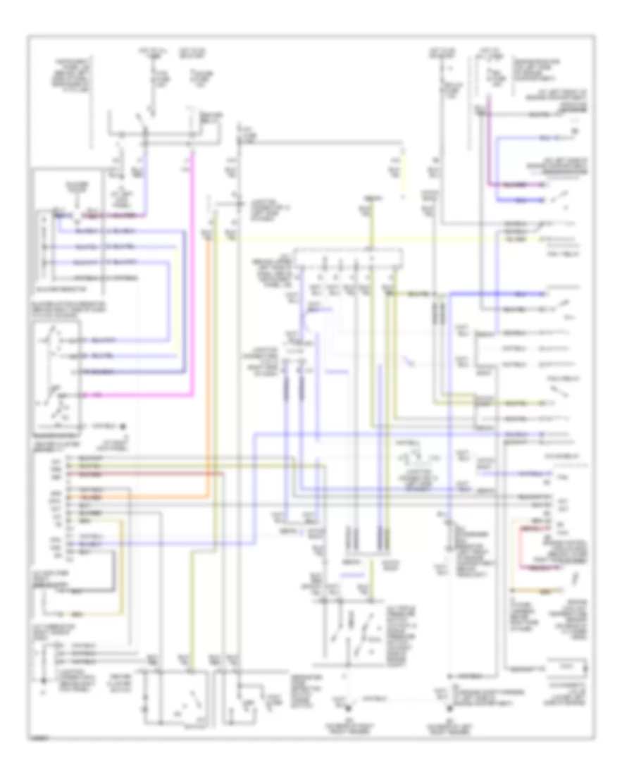
Heater Wiring Diagram for Toyota ECHO 2005

List of elements for Heater Wiring Diagram for Toyota ECHO 2005:
- A/c fuse 7.5a
- Air inlet control servo motor (under upper right side of dash, on hvac housing)
- Alt
- Blower motor
- Blower motor & resistor (behind right side of dash, in hvac housing)
- Blower resistor
- Blower switch
- Control circuit
- Ecu-ig fuse 7.5a
- Engine control module (ecm) (behind lower right side of dash)
- Engine room r/b (on left side of engine compartment)
- F/d
- Foot
- Foot mode switch
- Frs
- G10
- Gauge fuse 10a
- Generator
- Gnd
- H11
- Hatch back
- Heater relay
- Heater sub 1 relay
- Hot at all times
- Hot in on or start
- Htr fuse 40a
- Htr sub 1 fuse 50a
- Id (at left kick panel)
- If (at right kick panel)
- Inlet air position detection switch (inside switch)
- Instrument panel j/b (behind left side of dash, near base of ``a" pillar)
- Junction connector (left side of dash)
- Junction connector 7 (below instrument cluster)
- Junction connector 9 (behind right kick panel)
- Max hot
- Max hot & foot mode switch
- Max hot switch
- Mhsw
- Mode in
- Off
- Position switches
- Ptc amplifier (behind upper right side of dash, near instrument cluster)
- Ptc heater (behind left center of dash)
- Ptc1
- Ptu
- R/f1
- Rec
- Rec/frs
- Red
- Tach
- Tw1
- W/ tacho- meter
- W/o tacho- meter
- Water temperature sensor (behind upper right side of dash)
Manual A/C Wiring Diagram for Toyota ECHO 2005
List of elements for Manual A/C Wiring Diagram for Toyota ECHO 2005:
- (at left front of engine compartment)
- (on left side of engine compartment) engine room r/b
- A/c
- A/c amplifier (right side of dash)
- A/c condenser fan resistor (left front of engine compartment, behind headlight)
- A/c fuse 7.5a
- A/c magnetic valve (lower left side of engine)
- A/c mg relay
- A/c thermistor (right side of dash)
- A/c triple pressure switch (a/c dual & single pressure dual switch) (on right side of engine compt)
- A10
- Ac1
- Act
- Blower motor
- Blower motor & resistor (behind right side of dash, in hvac housing)
- Blower resistor
- Blower switch
- Center
- Center cluster switch
- Cfn+
- Cfn-
- Cluster
- Def
- Defroster mode detection switch (inside switch)
- E4 (in engine compt harness, at left side of engine compartment)
- Ea (on rear of right front fender)
- Ec (on rear of left front fender)
- Ecu-ig fuse 7.5a
- Engine control module (ecm) (behind lower right side of dash)
- Engine coolant temperature sensor (on rear of cylinder head)
- Engine room r/b (on left side of engine compartment)
- Fan
- Fan 1 relay
- Fan 2 relay
- Foot & def
- Gauge fuse 10a
- Gnd
- H18
- Hatch back
- Heater relay
- Hot at all times
- Hot in on or start
- Htr fuse 40a
- I10
- I2 (in dash harness, behind right side of dash)
- Id (at left kick panel)
- If (at right kick panel)
- Instrument panel j/b (behind left side of dash, near base of ``a" pillar)
- J/c 1 (behind upper left side of dash, above instrument panel j/b)
- J13
- J14
- Junction connector 12 (left side of dash)
- Junction connector 9 (behind right kick panel)
- Junction connectors 13 & 14 (right side e of dash)
- Mgc
- Off
- Prs
- Radiator fan motor
- Rdi fuse 30a
- Sedan
- Single
- Switch
- Thw
 English