AIR CONDITIONING
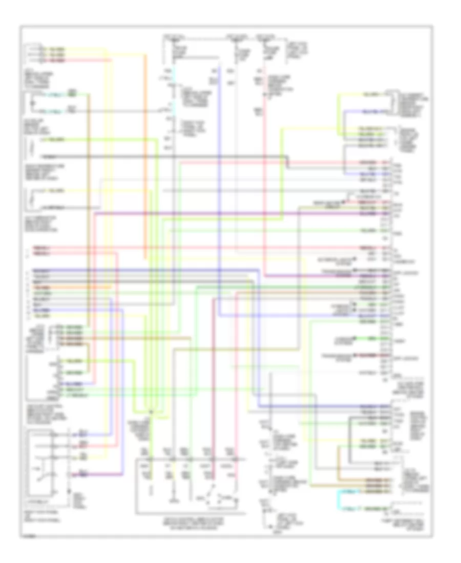
A/C Wiring Diagram (1 of 2) for Toyota Land Cruiser 1998

List of elements for A/C Wiring Diagram (1 of 2) for Toyota Land Cruiser 1998:
- (a)
- (b)
- (dash wire harness, behind combination meter) i6
- (dash wire harness, top center of dash)
- (dash wire harness, top center of dash) i10
- (front right side of fender apron) g101
- (front right side of fender apron) g103
- A shielded
- A/c amplifier (center ecu) (behind center of dash)
- A/c amplifier (rear) (on right side of cargo area)
- A/c condenser fan motor
- A/c condenser fan relay (on left front of engine compartment, near radiator)
- A/c dual pressure switch (w/o rear a/c) a/c triple pressure switch (a/c dual & single pressure switch) (w/rear a/c) (on left front of engine compartment, near headlight assembly)
- A/c fuse 20a
- A/c magnetic clutch & lock sensor (on a/c compressor)
- A10
- A11
- A12
- A13
- A14
- A15
- A16
- A17
- A18
- A19
- A20
- A21
- A22
- A23
- A24
- A25
- A26
- Ac1
- Act
- Air vent mode control servo motor (behind left center of dash, on heater-a/c housing)
- B/l
- B10
- B11
- B12
- B13
- B14
- B15
- B16
- B20
- Blower motor controller (behind right side of dash)
- C14
- Cds fan fuse 20a
- Cid
- Clk
- Control circuit
- Csd
- Def
- Defogger system
- E11
- E19
- Engine room j/b (on left inner fender panel)
- F/d
- Face
- Foot
- Foot/ def
- Frblw
- Frcid
- Frclk
- Frcsd
- Frhr
- Frlat
- G200
- G301 (under front passenger's seat)
- Gnd
- Hot at all times
- Hot in on or start
- Htr fuse 60a
- I10
- I10 (dash wire harness, top center of dash)
- Ig1
- Ign
- Instrument cluster system
- J/c 1 (left side of dash)
- J/c 38 (right side of cargo area)
- J/c 39 (right side of cargo area)
- L13
- L14
- L15
- L17
- L19
- Lat
- Left kick panel j/b (at left kick panel)
- Left kick panel j/b (left kick panel)
- Lock
- Mg clt relay
- Mgc
- Mrrhr
- Position switches
- Psw
- Rdfgr
- Rear a/c circuit
- Rear heater circuit
- Red
- Rhfr
- Rhi-i
- Rhr
- Rlo-i
- Rrmgv
- Spd
- Ver1
- Ver2
- Ver3
- Ver4
- W/o rear a/c
- W/rear a/c circuit
- W/rear a/c only
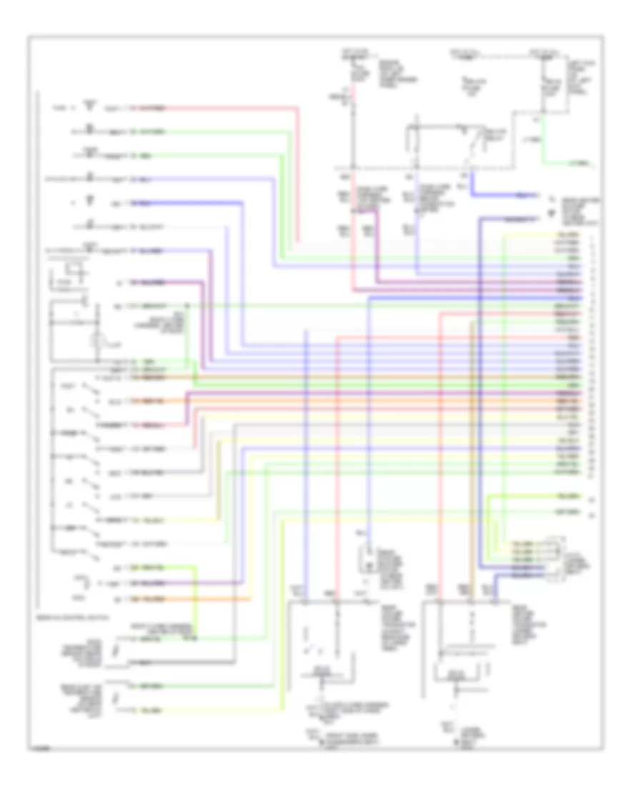
A/C Wiring Diagram (2 of 2) for Toyota Land Cruiser 1998
List of elements for A/C Wiring Diagram (2 of 2) for Toyota Land Cruiser 1998:
- (dash wire harness, behind combination meter) i5
- A/c
- A/c ambient temperature sensor (near right headlight assembly)
- A/c amplifier (center ecu) (behind center of dash)
- A/c solar sensor (on top left side of dash)
- A/c thermistor (behind right side of dash, on evaporator)
- Acc
- Act
- Aif
- Air
- Air inlet control servo motor (behind right side of dash, on heater - a/c housing)
- Air mix control servo motor (behind right center of dash, on heater-a/c housing)
- C10
- C11
- C12
- Cigar fuse 15a
- Combination meter) i6
- Cool
- D10
- D11
- D12
- D13
- D14
- D15
- D16
- D17
- D18
- D19
- D20
- D21
- D22
- D25
- Diff lock sw
- E12
- E18
- E21
- Ecu-b fuse 15a
- Els2
- Engine control module (behind right side of dash)
- Engine room j/b (on left inner fender panel)
- Exterior lights system
- Framc
- Framh
- Frs5
- Frsg
- Frte
- Frtp
- Frtr
- G200
- G203 (right kick panel)
- Gauge fuse 15a
- Gnd
- Hazard sw
- Hot at all times
- Hot in acc or on
- Hot in on start
- I-s/bw
- I-sec
- I10 (dash wire harness, top center of dash)
- I14 (dash wire harness, top right side of dash)
- I54
- Illum
- Ind
- Interior lights system
- J/c 1 (left side of dash)
- J/c 16 (behind upper left side of dash, taped to harness)
- J/c 4 (behind upper left side of dash, taped to harness)
- J/c 5 (behind upper left side of dash, taped to harness)
- J/c 9 (behind upper left side of dash, taped to harness)
- L10
- Led
- Left kick panel j/b (at left kick panel)
- Left kick panel j/b (left kick panel)
- Mcool
- Mfrs
- Mhot
- Mrec
- Mtr relay
- P26
- Pnk
- Rear heater circuit
- Rh-s
- Right kick panel j/b (right kick panel)
- Room temperature sensor (front) (behind left center of dash)
- Tach
- Tam
- Theft deterent ecu (below center of dash)
- Thwo
- Tpi
- Transmissions system
- W/o rear a/c
- Warm
- Warning systems
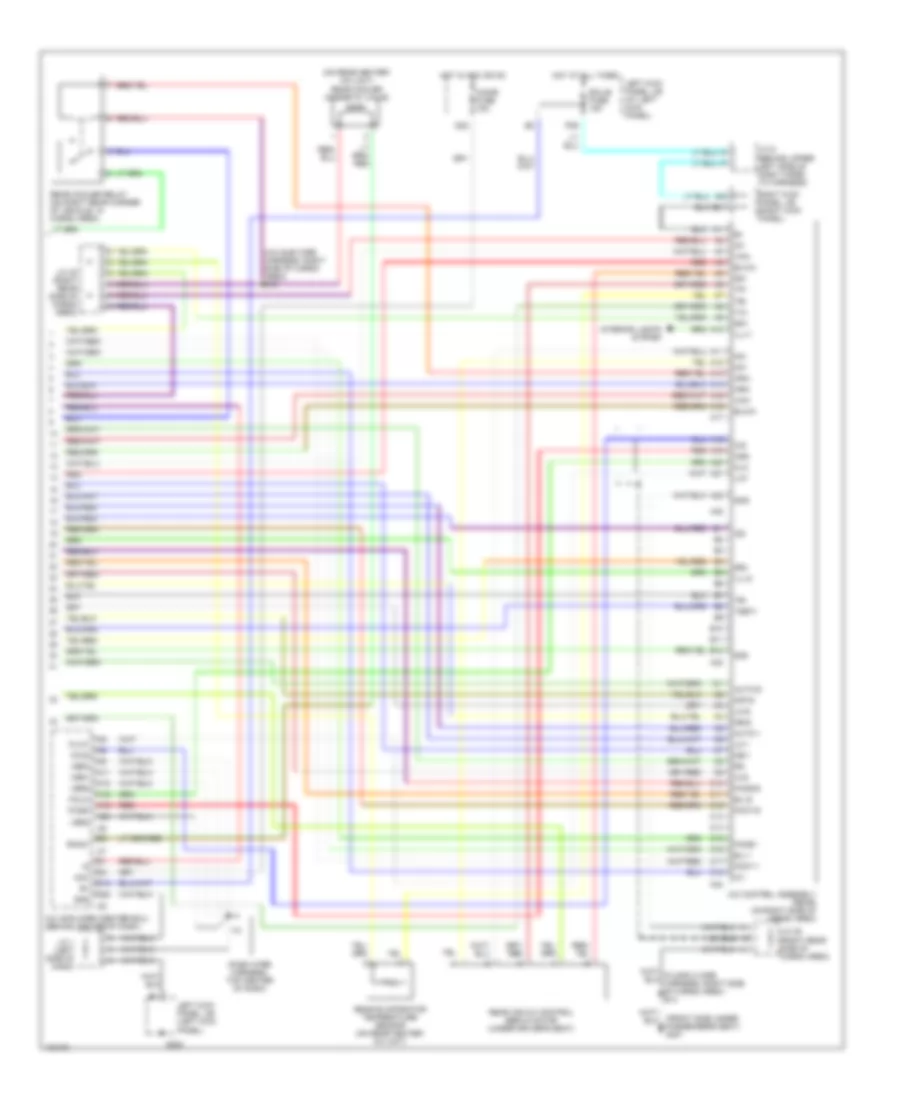
Rear A/C Wiring Diagram (1 of 2) for Toyota Land Cruiser 1998
List of elements for Rear A/C Wiring Diagram (1 of 2) for Toyota Land Cruiser 1998:
- (dash wire harness, top center of dash) i10
- (front side under passenger's seat) g301
- (roof 2 wire harness, center of roof) b13
- (under driver's seat) g300
- A/c fuse 20a
- Auto
- Auto-1
- Auto-s
- B/l
- B/l-i
- B/ls
- B13 (roof 2 wire harness, center of roof)
- B20
- Behind combination meter) i7
- Cool
- Engine room j/b (on left inner fender panel)
- Face
- Face-i
- Face-s
- Foot
- Foot-i
- Foot-s
- Hi-i
- Hi-s
- Hot
- Hot at all times
- Hot in on or start
- Ill
- Illum
- J/c 31 (under driver's seat)
- Left kick panel j/b (at left kick panel)
- Lo-i
- Lo-s
- Me-i
- Me-s
- Off
- Off-s
- Rear a/c control switch
- Rear cooler blower motor (in rear heater a/c unit)
- Rear cooler power transistor (in right rear side of cargo area)
- Rear heater blower motor (in rear heater unit)
- Rear heater power transistor (under driver's seat)
- Rear inlet air temperature sensor (on rear heater-a/c unit)
- Red
- Room temperature sensor (rear) (on middle of roof)
- Rr ac fuse 30a
- Rr htr fuse 10a
- Rr htr relay
- Solid state
- Srg
- T-set
Rear A/C Wiring Diagram (2 of 2) for Toyota Land Cruiser 1998
List of elements for Rear A/C Wiring Diagram (2 of 2) for Toyota Land Cruiser 1998:
- (a/c sub wire harness, right side of cargo area) b19
- (dash wire harness, top center of dash)
- (front side under passengers seat) g301
- (on rear heater- a/c unit) rear cooler magnetic valve
- A/c amplifier (center ecu) (behind center of dash)
- A/c control assembly (rear) (on right side of cargo area)
- A10
- A11
- A12
- A13
- A14
- A15
- A16
- A17
- A18
- A19
- A20
- A21
- A22
- A25
- A32
- A33
- A34
- Acc
- Auto-1
- Auto-s
- B/l-1
- B/l-s
- B10
- B11
- B12
- Blwrc
- Blwrh
- C10
- C11
- C12
- C13
- C14
- C15
- C16
- C17
- C18
- Cid
- Cigar fuse 15a
- Clk
- Csd
- D12
- D22
- E21
- Ecu-b fuse 15a
- Face-i
- Face-s
- Foot-1
- Foot-s
- Frcid
- Frclk
- Frcsd
- Frlat
- G200
- Gnd
- Hi-i
- Hi-s
- Hot at all times
- Hot in acc or on
- Hrrc
- Hrrh
- I10
- I54
- Ig1
- Ig2
- Ill+1
- Ill+2
- Interior lights system
- J/c 1 (left side of dash)
- J/c 38 (right rear side of cargo area)
- J/c 39 (right rear side of cargo area)
- J/c 9 (behind upper left side of dash taped to harness)
- Lat
- Left kick panel j/b (at left kick panel)
- Left kick panel j/b (left kick panel)
- Lo-1
- Lo-s
- Mcr
- Me-1
- Me-s
- Mhr
- Off-s
- P26
- Rear air mix control servo motor (under driver's seat)
- Rear cooler relay (on right rear corner of vehicle, in cargo area)
- Rear evaporator temperature sensor (on rear heater- a/c unit)
- Red
- Right kick panel j/b (right kick panel)
- Rrmgv
- S51
- S52
- Sg1
- Sg2
- Shield
- Ter
- Tpr
- Trr
- Tsetr
- Tinr
- Ver1
- Ver2
- Ver3
- Ver4
- Vmrc
- Vmrh
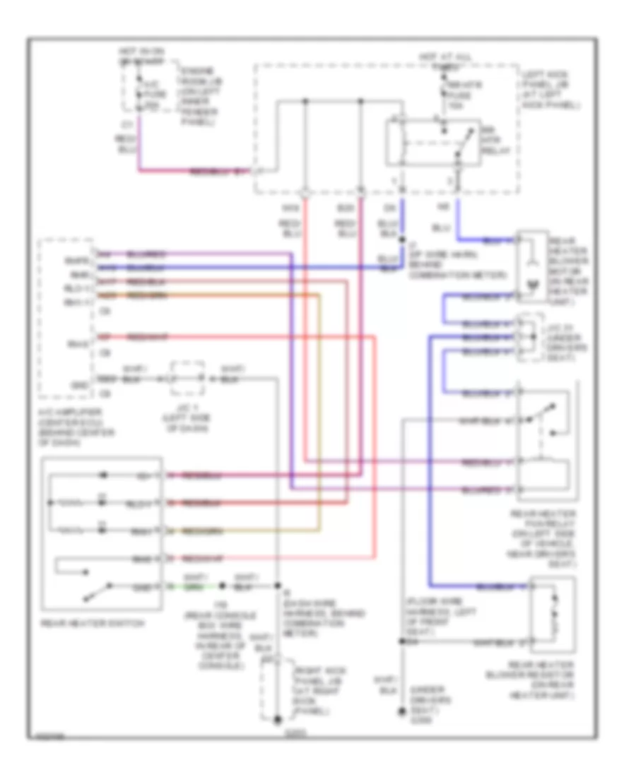
Rear Heater Wiring Diagram for Toyota Land Cruiser 1998
List of elements for Rear Heater Wiring Diagram for Toyota Land Cruiser 1998:
- (floor wire harness, left of front seat) b4
- (under driver's seat) g300
- A/c amplifier (center ecu) (behind center of dash)
- A/c fuse 20a
- A16
- A17
- A26
- B20
- D22
- Engine room j/b (on left inner fender panel)
- G203
- Gnd
- Hot at all times
- Hot in on or start
- I18 (rear console box wire harness, in rear of center console)
- I6 (dash wire harness, behind combination meter)
- I7 (i/p wire harn, behind combination meter)
- Ig+
- J/c 1 (left side of dash)
- J/c 31 (under driver's seat)
- Left kick panel j/b (at left kick panel)
- N18
- Rear heater blower motor (in rear heater unit)
- Rear heater blower resistor (on rear heater unit)
- Rear heater fan relay (on left side of vehicle, near driver's seat)
- Rear heater switch
- Rh-s
- Rh1-1
- Rhfr
- Rhi-i
- Rhr
- Rhs
- Right kick panel j/b (at right kick panel)
- Rlo-1
- Rr htr fuse 10a
- Rr htr relay