AIR CONDITIONING
A/C Wiring Diagram for Toyota T100 SR5 1995

List of elements for A/C Wiring Diagram for Toyota T100 SR5 1995:
- (2.7l a/t) (2.7l m/t)
- (3.4l a/t) (3.4l m/t)
- 1994 vftc c
- 2.7l
- A/c amplifier (right side of i/p)
- A/c dual pressure switch (right side of i/p)
- A/c fuse 10a
- A/c idle-up valve (rear of engine)
- A/c magnetic clutch (right front of engine)
- A/c switch
- A/c thermistor (right side of i/p)
- A7 b10 a20 b7
- All 3.4l and 1995
- Alt fuse 80a
- B8 a5
- Blower motor (right side of i/p)
- Blower resistor (right side of i/p)
- Blower switch
- C2 d1 c10 d2
- Engine control module (right side of i/p)
- Engine controls system (efi main relay)
- G200 (left kick panel)
- Gauge fuse 10a
- Heater fuse 30a
- Heater relay
- Hot at all times
- Hot in run or start
- Integration relay
- Interior lights system (rheostat)
- Interior lights system (tail fuse)
- J/b 1 (left kick panel)
- Off
- R/b 2 (left side of engine compt)
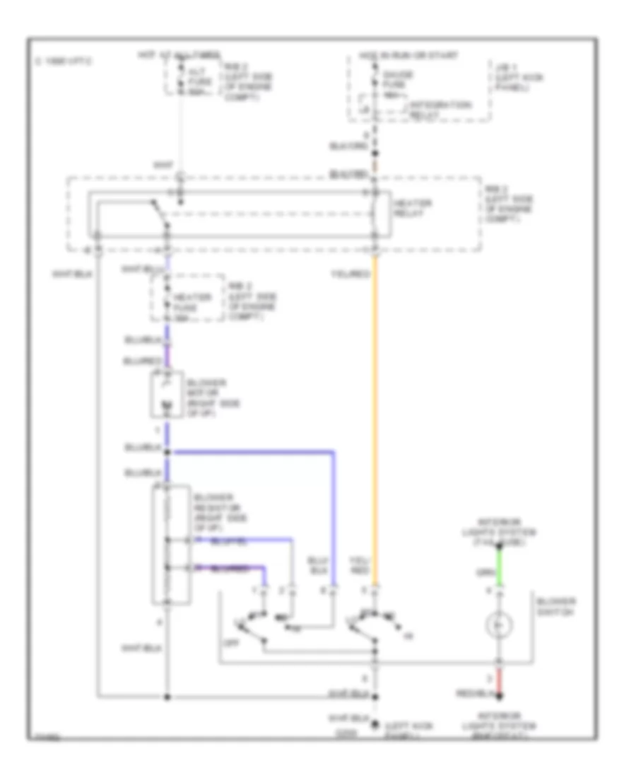
Heater Wiring Diagram for Toyota T100 SR5 1995
List of elements for Heater Wiring Diagram for Toyota T100 SR5 1995:
- (left kick panel)
- Alt fuse 80a
- Blower motor (right side of i/p)
- Blower resistor (right side of i/p)
- Blower switch
- C 1995 vftc
- G200
- Gauge fuse 10a
- Heater fuse 30a
- Heater relay
- Hot at all times
- Hot in run or start
- Integration relay
- Interior lights system (rheostat)
- Interior lights system (tail fuse)
- J/b 1 (left kick panel)
- Off
- R/b 2 (left side of engine compt)
 English