ANTI-LOCK BRAKES
Anti-lock Brake Wiring Diagrams (1 of 2) for Toyota Celica GT-S 2000

List of elements for Anti-lock Brake Wiring Diagrams (1 of 2) for Toyota Celica GT-S 2000:
- A10
- A11
- Abs 1 fuse 40a
- Abs 2 fuse 25a
- Abs ecu (behind center of dash)
- Abs mtr relay
- Abs sol relay
- Brl
- D/g
- Data link connector 3 (under left side of dash, near kick panel)
- Engine room j/b (on left side of engine compt)
- Engine room r/b 1 (on left side of engine compt)
- Fl+
- Fl-
- Fr+
- Fr-
- G203 (right kick panel)
- Gnd1
- Gnd2
- Hot at all times
- Ig1
- Instrument panel j/b (behind panel on right side of center console)
- J/c 10 (under right side of dash, on center of door pillar)
- Left front abs speed sensor
- Left rear abs speed sensor
- Parking brake switch (on base of park brake lever)
- Pnk
- Red
- Right front abs speed sensor
- Right rear abs speed sensor
- Rkb
- Rl+
- Rl-
- Rr+
- Rr-
- Sflh
- Sflr
- Sfrh
- Sfrr
- Sil
- Srlh
- Srlr
- Srrh
- Srrr
- Stp
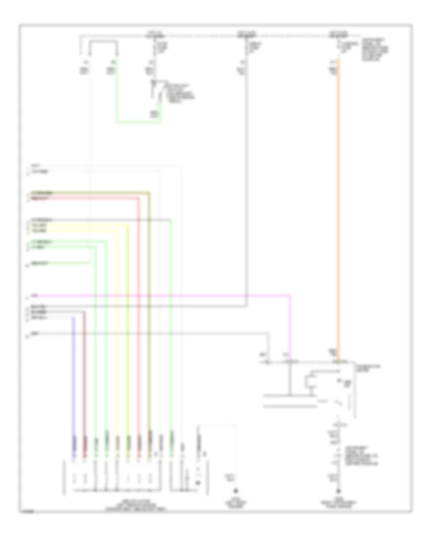
Anti-lock Brake Wiring Diagrams (2 of 2) for Toyota Celica GT-S 2000
List of elements for Anti-lock Brake Wiring Diagrams (2 of 2) for Toyota Celica GT-S 2000:
- Abs actuator (left rear of engine compartment, behind battery)
- Abs ind
- Abs-ig fuse 5a
- C12
- C13
- Combination meter
- G102 (left front fender)
- G206 (right instrument panel brace)
- Hot at all times
- Hot in on or start
- I12
- Instrument panel j/b (behind panel on right side of center console)
- M11
- M20
- Stop fuse 10a
- Stoplight switch (on bracket, above brake pedal)
- Warning fuse 5a