ANTI-LOCK BRAKES
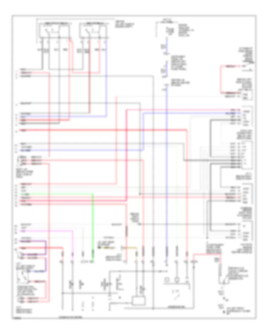
Anti-lock Brakes Wiring Diagram, with VSC (1 of 2) for Toyota Corolla LE 2005

List of elements for Anti-lock Brakes Wiring Diagram, with VSC (1 of 2) for Toyota Corolla LE 2005:
- (at front side of right fender) ea
- +bs
- A11
- A22
- Abs 1 fuse 30a
- Abs 2 fuse 50a
- Acc
- Am2 fuse 15a
- B14
- B21
- Brl
- C13
- C14
- Canh
- Canl
- Center j/b (behind center of dash)
- Csw
- D/g
- Ecu-b fuse 10a
- Ecu-ig fuse 10a
- Eng+
- Eng-
- Engine control module (behind right side of dash, below glove box)
- Engine room r/b (integral to engine room j/b)
- Fl+
- Fl-
- Fr+
- Fr-
- Gauge fuse 10a
- Gnd1
- Gnd2
- Hot at all times
- Hot in on or start
- I7 (in instrument panel wire, behind right side of dash)
- Ig1
- Ignition switch
- Ind
- Init
- Instrument panel j/b (behind left side of dash, at lower finish panel)
- J/c 6 (behind left side of dash)
- J/c 7 (at right kick panel)
- Left front abs speed sensor (on inside of left front wheel assembly)
- Left rear abs speed sensor (on inside of left rear wheel assembly)
- Lock
- Mrf
- Neo
- Off
- Pkb
- Pnk
- Red
- Right front abs speed sensor (on inside of right front wheel assembly)
- Right j/b (behind upper right side of dash)
- Right rear abs speed sensor (on inside of right rear wheel assembly)
- Rl+
- Rl-
- Rr+
- Rr-
- Skid control ecu w/ actuator (at right front side of engine compt)
- Sp1
- Start
- Stop fuse 15a
- Stop light switch (on bracket, above brake pedal)
- Stp
- Tire pressure warning standardization switch
- Trac off switch
- Trc+
- Trc-
- Tsi
- Vsc warning buzzer
- Vsc+
- Vsc-
- Vscw
- Wfse
- Wtir
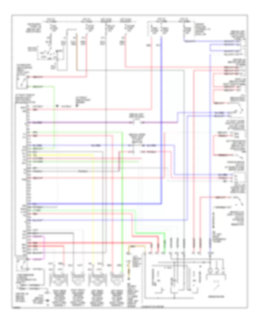
Anti-lock Brakes Wiring Diagram, with VSC (2 of 2) for Toyota Corolla LE 2005
List of elements for Anti-lock Brakes Wiring Diagram, with VSC (2 of 2) for Toyota Corolla LE 2005:
- (at base of park brake lever) parking brake switch
- (at left rear of engine) eb
- (behind left side of dash) daytime running light relay
- (behind right side of dash) i7
- (on left front suspension tower) ed
- Abs ind
- Abs mtr cut relay
- Abs mtr relay
- Abs r/b (on left side of engine compt)
- B16
- B20
- B22
- Bat
- Brake fluid level warning switch (on brake fluid reservoir)
- Brake ind
- Brk
- C16
- C19
- C20
- Canh
- Canl
- Center j/b (behind center of dash)
- Combination meter
- Data link connector 3 (below left end of dash)
- Dome fuse 15a
- Engine room r/b (integral to engine room j/b)
- Ess
- Gnd
- Hot at all times
- I7 (in instrument panel wire, behind right side of dash)
- Ig1
- Ind pressure tire
- Instrument panel j/b (behind left side of dash, at lower finish panel)
- J/c 1 (at left side of engine compt)
- J/c 11 (behind right side of dash)
- J/c 3 (behind right side of dash)
- J/c 4 (behind right side of dash)
- Park/neutral position switch (on left side of transaxle)
- Pkb
- Pnk
- Red
- Right j/b (behind upper right side of dash)
- Sil
- Slip ind
- Speedometer
- Steering sensor (right side of steering column)
- Vsc ind
- Wfse
- Yaw rate sensor (left side of center console)
Anti-lock Brakes Wiring Diagram, without VSC for Toyota Corolla LE 2005
List of elements for Anti-lock Brakes Wiring Diagram, without VSC for Toyota Corolla LE 2005:
- (at front side of right fender) ea
- (at right side of engine compt) skid control ecu w/ actuator
- (behind left side of dash) j/c 6
- (behind left side of dash) instrument panel j/b
- (behind upper right side of dash) right j/b
- (on bracket, above brake pedal) stop light switch
- +bm
- +bs
- A/t shift lever position switch (on left side of transaxle)
- Abs 1 fuse 30a
- Abs 2 fuse 40a
- Abs ind
- Acc
- Am2 fuse 15a
- B14
- B16
- B20
- B21
- B22
- Brake fluid level warning switch (on brake fluid reservoir)
- Brake ind
- Brk
- Brl
- C13
- C14
- C19
- C20
- Center j/b (behind center of dash)
- Center j/b (behind center of dash)
- Combination meter
- D/g
- Data link connector 3 (below left side of dash)
- Daytime running light relay (behind left side of dash)
- Dome fuse 15a
- Eb (except xrs: at rear left side of cylinder head) (xrs: left rear of engine)
- Ecu-ig fuse 10a
- Ed (at left front suspension tower)
- Engine room r/b (integral to engine room j/b)
- Fl+
- Fl-
- Fr+
- Fr-
- Gauge fuse 10a
- Gnd1
- Gnd2
- Hot at all times
- Hot in on or start
- Ig1
- Ignition switch
- Ind tire pressure
- Init
- Instrument panel j/b (behind left side of dash)
- J/c 3 (behind right side of dash)
- J/c 4 (behind right side of dash)
- J/c 6 (behind left side of dash)
- Left front abs speed sensor (on inside of left front wheel assembly)
- Left rear abs speed sensor (on inside of right rear wheel assembly)
- Lock
- Off
- Parking brake switch (at base of park brake lever)
- Pkb
- Red
- Right front abs speed sensor (on inside of right front wheel assembly)
- Right j/b (behind upper right side of dash)
- Right rear abs speed sensor (on inside of right rear wheel assembly)
- Rl+
- Rl-
- Rr+
- Rr-
- Sil
- Sp1
- Speedometer
- Start
- Stop fuse 15a
- Stp
- Tire pressure warning standardization switch
- Tsi
- Wtir