ANTI-LOCK BRAKES
Anti-lock Brakes Wiring Diagram, Except Hybrid (1 of 2) for Toyota Highlander Hybrid 2009

List of elements for Anti-lock Brakes Wiring Diagram, Except Hybrid (1 of 2) for Toyota Highlander Hybrid 2009:
- +bs
- A2 (behind right front headlight)
- A3 (behind left front headlight)
- A36
- A4 (behind left end j/c a40
- Brake pedal load sensing switch (above brake pedal)
- Brk lp relay
- C13
- C14
- Canh
- Canl
- Csw
- D1 (behind right kick panel)
- D3 (behind right side of dash)
- D51
- Dlc 3
- Downhill assist control switch (if equipped)
- Ecu-ig 2 fuse 7.5a
- Engine room r/b
- F19
- Fl+
- Fl-
- Fr+
- Fr-
- Fsw+
- Gnd
- Gnd1
- Hdcs
- Hot at all times
- Hot in on or start
- Ig1
- Instrument panel j/b
- J/c a36 & d51
- J/c d52
- Left front speed sensor (left front wheel hub)
- Left rear speed sensor (2wd)
- Left rear speed sensor (4wd)
- Of dash)
- Parking brake switch (at base of parking brake pedal)
- Pkb
- Pnk
- Red
- Right front speed sensor (right front wheel hub)
- Right rear speed sensor (2wd) (right rear wheel hub)
- Right rear speed sensor (4wd) (right rear wheel hub)
- Rl+
- Rl-
- Rr+
- Rr-
- Skid control buzzer (behind left side of dash)
- Skid control ecu w/ actuator (right front of engine compt)
- Stop fuse 10a
- Stop light switch (above brake pedal)
- Stp
- Stp2
- Stpo
- Vsc 1 fuse 50a
- Vsc 2 fuse 30a
- Vsc off switch
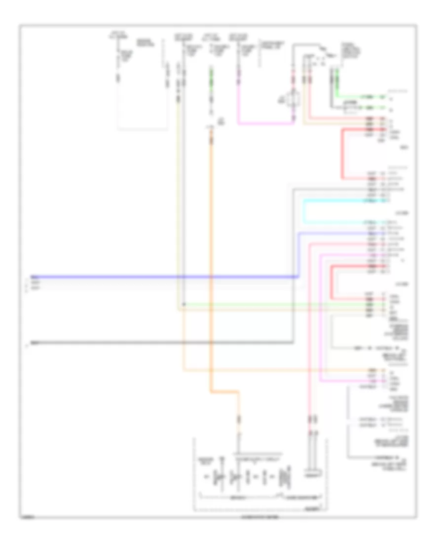
Anti-lock Brakes Wiring Diagram, Except Hybrid (2 of 2) for Toyota Highlander Hybrid 2009
List of elements for Anti-lock Brakes Wiring Diagram, Except Hybrid (2 of 2) for Toyota Highlander Hybrid 2009:
- +b(dome) or ig
- Abs ind
- Bat
- Buzzer
- Can if
- Canh
- Canl
- Combination meter
- Control ind assist downhill
- D10
- D36
- D4 (behind left kick panel)
- Drive ic
- Ecm
- Ecu-b fuse 10a
- Ecu-ig 2 fuse 7.5a
- Engine room r/b
- Ess
- F19
- G12
- Gauge 1 fuse 10a
- Gauge 2 fuse 7.5a
- Gnd
- H16
- Hot at all times
- Hot in on or start
- Ig2
- Ind master
- Ind vsc off
- Instrument panel j/b
- J/c b46
- J/c d55
- J/c d58
- J/c d59
- J/c e23
- J/c o36 (behind left side of rear bumper)
- Micro computer
- Nl rl
- O2 (behind left rear wheelwell)
- Park/ neutral position switch
- Pnk
- Red
- Slip ind
- Steering sensor (in steering column)
- Yaw rate sensor (under center console)
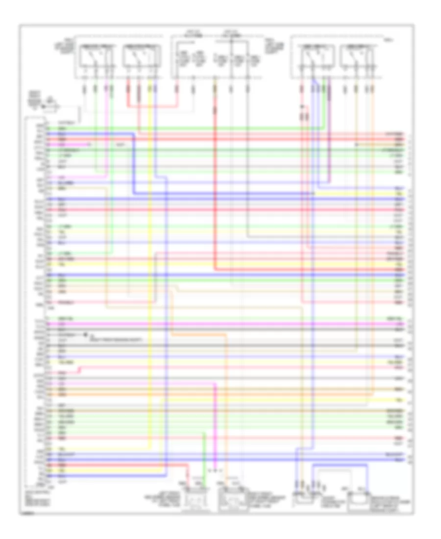
Anti-lock Brakes Wiring Diagram, Hybrid (1 of 3) for Toyota Highlander Hybrid 2009
List of elements for Anti-lock Brakes Wiring Diagram, Hybrid (1 of 3) for Toyota Highlander Hybrid 2009:
- (right front engine compt) a7
- A2 (right front engine compt)
- A45
- A46
- A56
- Abs 1 fuse 10a
- Abs 1 relay
- Abs 2 fuse 10a
- Abs 2 relay
- Abs 3 fuse 15a
- Abs mtr 1 fuse 50a
- Abs mtr 1 relay
- Abs mtr 2 fuse 50a
- Abs mtr 2 relay
- Brake stroke simulator cylinder (left rear of engine compt)
- Bs1
- Bs2
- Cty+
- Fl+
- Fl-
- Fla+
- Fla-
- Flr+
- Flr-
- Fr+
- Fr-
- Fra+
- Fra-
- Frr+
- Frr-
- Fss
- Gnd
- Gnd6
- Hot at all times
- Ig2
- J/c a57
- Lbl
- Left front abs speed sensor (at left front wheel hub)
- Mr1
- Mr2
- Mtt
- Nca
- Pac1
- Pck1
- Pck2
- Pfl
- Pfr
- Pmc1
- Pmc2
- Pnk
- Prl
- Prr
- R/b 2 (left side of engine compt)
- R/b 3 (left side of engine compt)
- R/b 4
- R1+
- R1-
- R2+
- R2-
- R3+
- R4+
- Red
- Right front abs speed sensor (at right front wheel hub)
- Rla+
- Rla-
- Rlr+
- Rlr-
- Rra+
- Rra-
- Rrr+
- Rrr-
- S55
- Sg1
- Sg2
- Short connector a55 & a56
- Skid control ecu (behind right side of dash)
- Smc1
- Smc2
- Stpo
- Vcm
- Vcm2
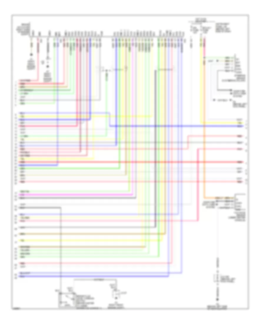
Anti-lock Brakes Wiring Diagram, Hybrid (2 of 3) for Toyota Highlander Hybrid 2009
List of elements for Anti-lock Brakes Wiring Diagram, Hybrid (2 of 3) for Toyota Highlander Hybrid 2009:
- A1 (right front engine compt)
- A24
- A53
- A54
- A7 (right front engine compt)
- Bat
- Bm1
- Bm2
- Brake actuator (right side of engine compt)
- Brake fluid level warning switch (brake master cylinder reservoir assembly)
- Bs1
- Bs2
- Canh
- Canl
- Computer data lines system
- D4 (behind left kick panel)
- Ecu-ig 1 fuse 7.5a
- Ess
- F11
- Fla+
- Fla-
- Flr+
- Flr-
- Fra+
- Fra-
- Frr+
- Frr-
- Gnd
- Gnd1
- Gnd2
- Hot in on or start
- Ig1
- Ign fuse 10a
- Instrument panel j/b (behind left side of dash)
- J/c
- J/c 57
- J/c a36 (behind left kick panel)
- Mtt
- Nca
- O2 (behind left side of rear bumper)
- Pca 1
- Pck 1
- Pck2
- Pfl
- Pfr
- Pmc 1
- Pmc2
- Pnk
- Prl
- Prr
- Red
- Rla+
- Rla-
- Rlr+
- Rlr-
- Rra+
- Rra-
- Rrr+
- Rrr-
- Smc1
- Smc2
- Steering sensor (in steering column)
- Vcm
- Vcm2
- Yaw rate sensor (under center console)
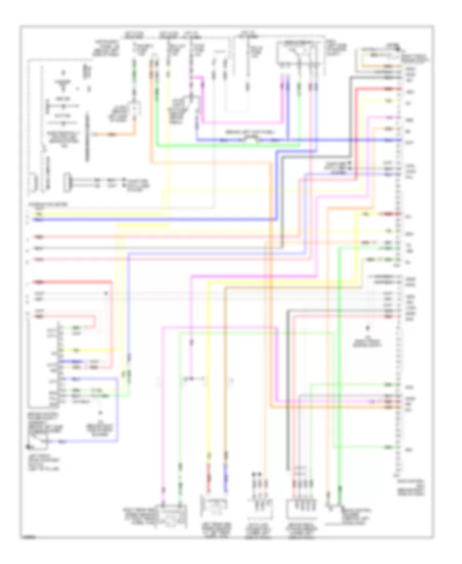
Anti-lock Brakes Wiring Diagram, Hybrid (3 of 3) for Toyota Highlander Hybrid 2009
List of elements for Anti-lock Brakes Wiring Diagram, Hybrid (3 of 3) for Toyota Highlander Hybrid 2009:
- (behind left kick panel) j/c a36
- +b(dome or ig)
- +bc
- +bi1
- +bi2
- +bo1
- +bo2
- A2 (right front engine compt)
- A44
- A47
- A7 (right front engine compt)
- Abs ind
- Brake pedal stroke sensor (under left side of dash)
- Brk lp relay
- Buzzer
- C13
- Can if
- Canh
- Canl
- Combination meter
- Computer data lines system
- Cty
- Cty+
- D10
- Data link connector 3 (under left side of dash)
- Drive ic
- Ecu b fuse 10a
- Ecu ig 2 fuse 7.5a
- Electronically controlled brake system ind
- Ena
- Exi
- Fail
- G12
- Gauge 2 fuse 7.5a
- Gnd
- Gnd2
- Gnd3
- Gnd4
- Gnd5
- Hot at all times
- Hot in on or start
- Ig1
- Ig2
- Instrument panel j/b (behind left side of dash)
- J/c a57
- J/c e23 (behind left side of dash)
- Left front door courtesy switch (left "b" pillar)
- Left rear abs speed sensor (at left rear wheel hub)
- Master ind
- Micro computer
- Nca
- O3 (behind right side of rear bumper)
- Out1
- Out2
- Pnk
- R/b 2 (left side of engine compt)
- Red
- Right rear abs speed sensor (at right rear wheel hub)
- Rl+
- Rl-
- Rr+
- Rr-
- Rss
- Sgsk
- Skg
- Skid control ecu (behind right side of dash)
- Sks
- Sks1
- Sks2
- Slip ind
- Stop fuse 10a
- Stop light switch (above brake pedal)
- Stp
- Vbz
- Vcsk