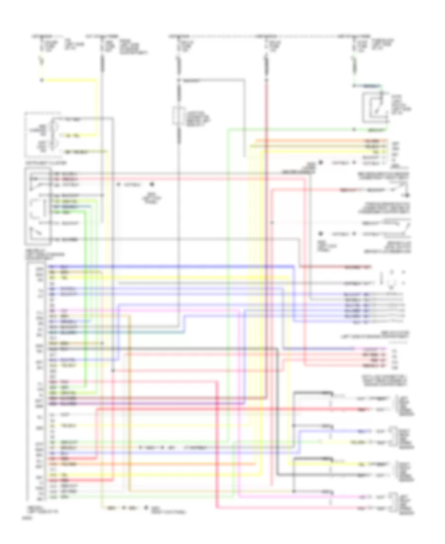
ANTI-LOCK BRAKES
Anti-lock Brake Wiring Diagrams for Toyota Land Cruiser 1994
List of elements for Anti-lock Brake Wiring Diagrams for Toyota Land Cruiser 1994:
- A10
- A11
- A12
- A13
- A14
- A15
- A16
- Abs actuator (left side of engine compartment)
- Abs deceleration sensor (under right front seat)
- Abs ecu (left side of i/p)
- Abs fuse 60a
- Abs relay (left side of engine compartment)
- Abs warning ind
- Ast
- B10
- B11
- B12
- B13
- B14
- B15
- B16
- B17
- B18
- B19
- B20
- B21
- B22
- B23
- B24
- B25
- B26
- Bat
- Brake fluid level switch (brake fluid reservoir)
- Data link connector 1 (right rear corner of engine compartment)
- Diff lock ind
- Ecu-b fuse 10a
- Ecu-ig fuse 15a
- Exi
- F/b (left side of i/p)
- Fl+
- Fl-
- Fr+
- Fr-
- Fss
- Fuse block (left side of i/p)
- G200 (left kick panel)
- G203 (right kick panel)
- G206 (under center console)
- Gauge fuse 10a
- Gnd
- Gs1
- Gs2
- Gst
- Hot at all times
- Hot in run
- Ig1
- Instrument cluster
- Junction connector (behind left side of i/)
- Left front abs speed sensor
- Left rear abs speed sensor
- Nca
- Parking brake switch (under front center of passenger compartment)
- Pkb
- Pnk
- R/b #2 (left side of engine compartment)
- Red
- Right front abs speed sensor
- Right rear abs speed sensor
- Rl+
- Rl-
- Rr+
- Rr-
- Rss
- Sfl
- Sfr
- Srr
- Stop fuse 10a
- Stop light switch (left side of i/p)
- Stp
 English