ANTI-LOCK BRAKES
Anti-lock Brake Wiring Diagrams for Toyota Tercel CE 1998
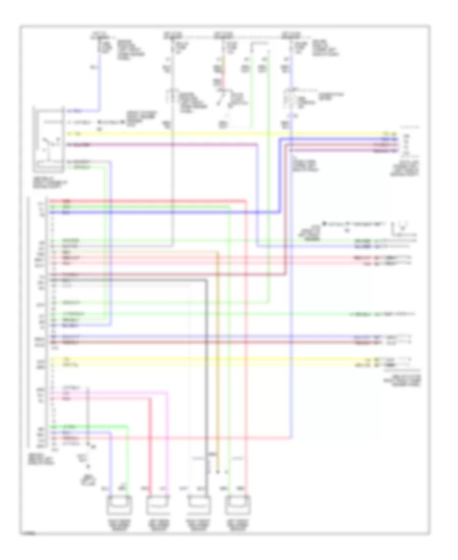
List of elements for Anti-lock Brake Wiring Diagrams for Toyota Tercel CE 1998:
- (front of right front fender) fender) g100
- A12
- A13
- Abs actuator (right front inner fender panel)
- Abs ecu (behind left side of dash)
- Abs fuse 60a
- Abs relay (right corner of engine compt)
- Abs warning ind
- Combination meter
- Data link connector 1 (left side of engine compt)
- Driver side j/b (under left side of dash)
- Ecu-ig fuse 5a
- Engine room r/b (left front inner fender panel)
- Fl+
- Fl-
- Fr+
- Fr-
- Fss
- G100 (front of left front fender)
- G904 (left "c" pillar)
- Gauge fuse 10a
- Gnd
- Hot at all times
- Hot in on or start
- I4 (dash harn, upper left end of dash)
- Ig1
- Left front abs speed sensor
- Left rear abs speed sensor
- Pnk
- Red
- Right front abs speed sensor
- Right rear abs speed sensor
- Rl+
- Rl-
- Rr+
- Rr-
- Slh1
- Slh2
- Slr
- Srh1
- Srh2
- Srr
- Stop fuse 10a
- Stop light switch
- Stp
 English