ANTI-LOCK BRAKES
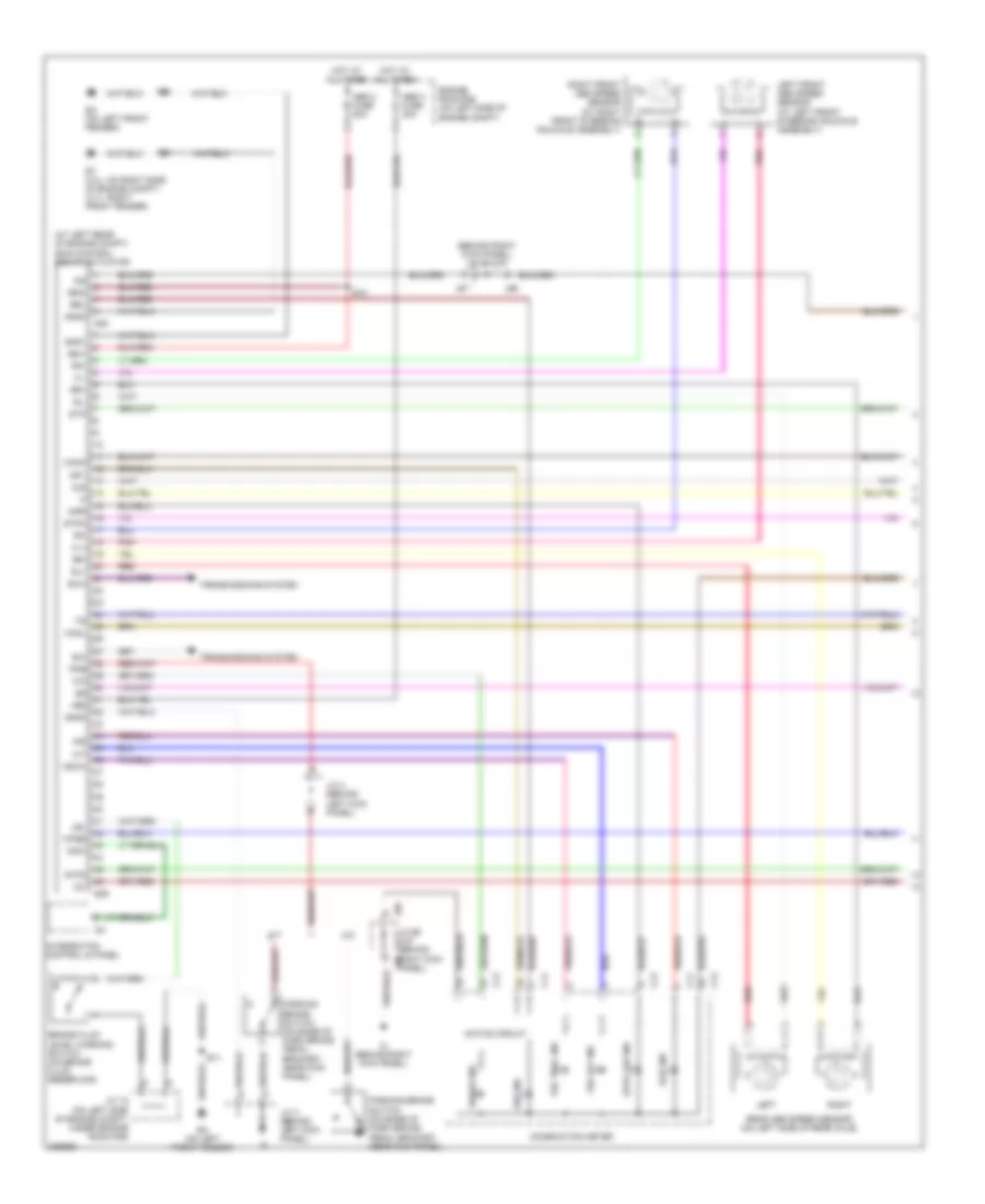
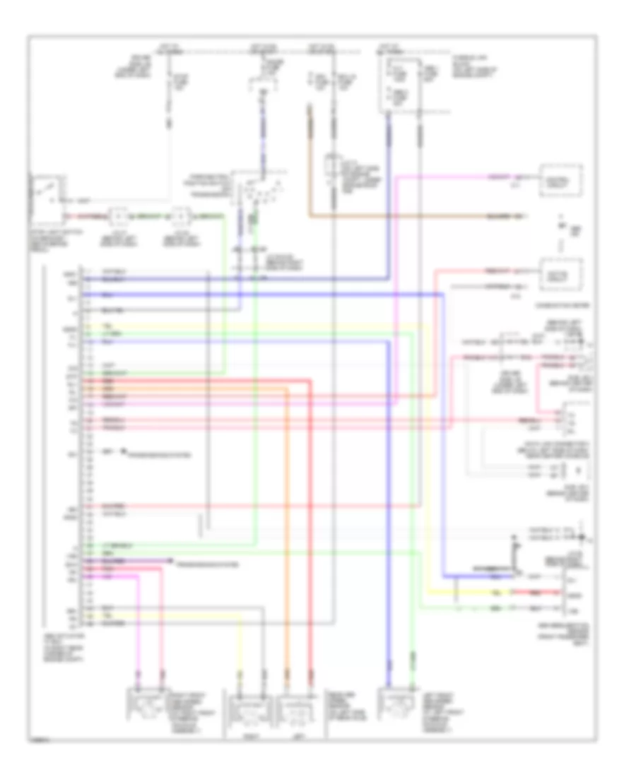
Anti-lock Brakes Wiring Diagram, Access/Standard Cab without VSC for Toyota Tundra Limited 2006

List of elements for Anti-lock Brakes Wiring Diagram, Access/Standard Cab without VSC for Toyota Tundra Limited 2006:
- (behind upper left side of dash, near instrument cluster) (a/t) diode
- (behind upper left side of dash, near instrument cluster) j/c 8
- (below left side of dash, near center console) data link connector 3
- +bm
- +bs
- A/t
- Abs 2 fuse 50a
- Abs 3 fuse 30a
- Abs actuator w/ ecu (in right rear corner of engine compartment)
- Abs deceleration sensor (access cab: under front of center console) (standard cab: under right front seat)
- Abs ind
- Acc fuse 15a
- Active circuit
- C11
- C12
- Combination meter
- Control circuit
- D j66
- D/g
- Driver side j/b (behind lower left side of dash)
- E16
- Ecu ig fuse 5a
- Engine room r/b (on left side of engine compt)
- Exi
- Exi4
- F10
- Fl+
- Fl-
- Fr+
- Fr-
- G11
- G13
- Gauge fuse 10a
- Ggnd
- Gl1
- Gnd1
- Gnd2
- Hot at all times
- Hot in on or acc
- Hot in on or start
- I16
- Ig1
- Ih (behind right kick panel)
- J/c 10 (behind upper left side of dash, near instrument cluster)
- J/c 13 (behind right kick panel)
- J/c 28 & 29 (behind upper right side of dash, near passenger's air bag) j29
- J/c 66 & 67 (behind right kick panel)
- J/c 66 (behind right kick panel)
- J/c 8 (behind upper left side of dash, near instrument cluster)
- J/c 9 (behind upper left side of dash, near instrument cluster)
- J28
- Left
- Left front abs speed sensor (at left front steering knuckle assembly)
- Nca
- Park/neutral position switch (a/t) (on transmission)
- Pnk
- Rear abs speed sensor (on left side of rear axle)
- Red
- Right
- Right front abs speed sensor (at right front steering knuckle assembly)
- Rl+
- Rl-
- Rr+
- Rr-
- Sil
- Spi
- Stop fuse 15a
- Stoplight switch (on bracket, above brake pedal)
- Stp
- Transmissions system
- Vgs
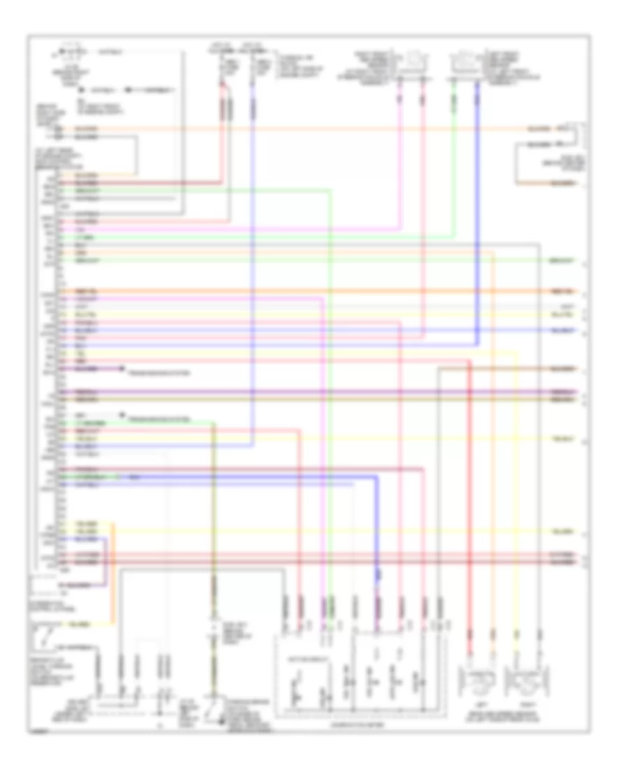
Anti-lock Brakes Wiring Diagram, Access/Standard Cab withVSC (1 of 2) for Toyota Tundra Limited 2006
List of elements for Anti-lock Brakes Wiring Diagram, Access/Standard Cab withVSC (1 of 2) for Toyota Tundra Limited 2006:
- (at left rear of engine compt) skid control ecu w/ actuator
- (behind right kick panel) j/c 66 & 67
- +bm1
- +bm2
- +bs
- A/t
- Abs 2 fuse 50a
- Abs 3 fuse 30a
- Abs ind
- Active circuit
- Auto lsd ind
- Brake fluid level warning switch (on brake fluid reservoir)
- Brake ind
- Brl
- C11
- C12
- Canh
- Canl
- Combination meter
- Csw
- D/g
- E11
- E12
- Ea (on left front fender)
- Engine room r/b (on left side of engine compt)
- Et (4.0l: on right side of engine compt) (4.7l: right front fender)
- Exi
- Exi4
- Fl+
- Fl-
- Fr+
- Fr-
- Gnd1
- Gnd2
- Gnd3
- Hot at all times
- I24
- Ig1
- Ig2
- Ih (behind right kick panel)
- Ind
- Infr
- Integration control & panel
- J/c 18 (on left side of engine compt, under engine room r/b)
- J/c 3 (behind left kick panel)
- J/c 4 (behind left kick panel)
- J/c 66 & 67 (behind j67 right kick panel)
- J66
- J67
- Lbl
- Left
- Left front abs speed sensor (at left front steering knuckle assembly)
- M/t
- Parking brake switch (on base of park brake pedal bracket, near kick panel)
- Pkb
- Pnk
- Rear abs speed sensor (on left side of rear axle)
- Red
- Right
- Right front abs speed sensor (at right front steering knuckle assembly)
- Rl+
- Rl-
- Rr+
- Rr-
- S29
- S30
- Slip ind
- Sp1
- Stp
- Stp2
- Stpo
- Transmissions system
- Vsc off ind
- Vsc trac ind
- Vscw
- Wfse
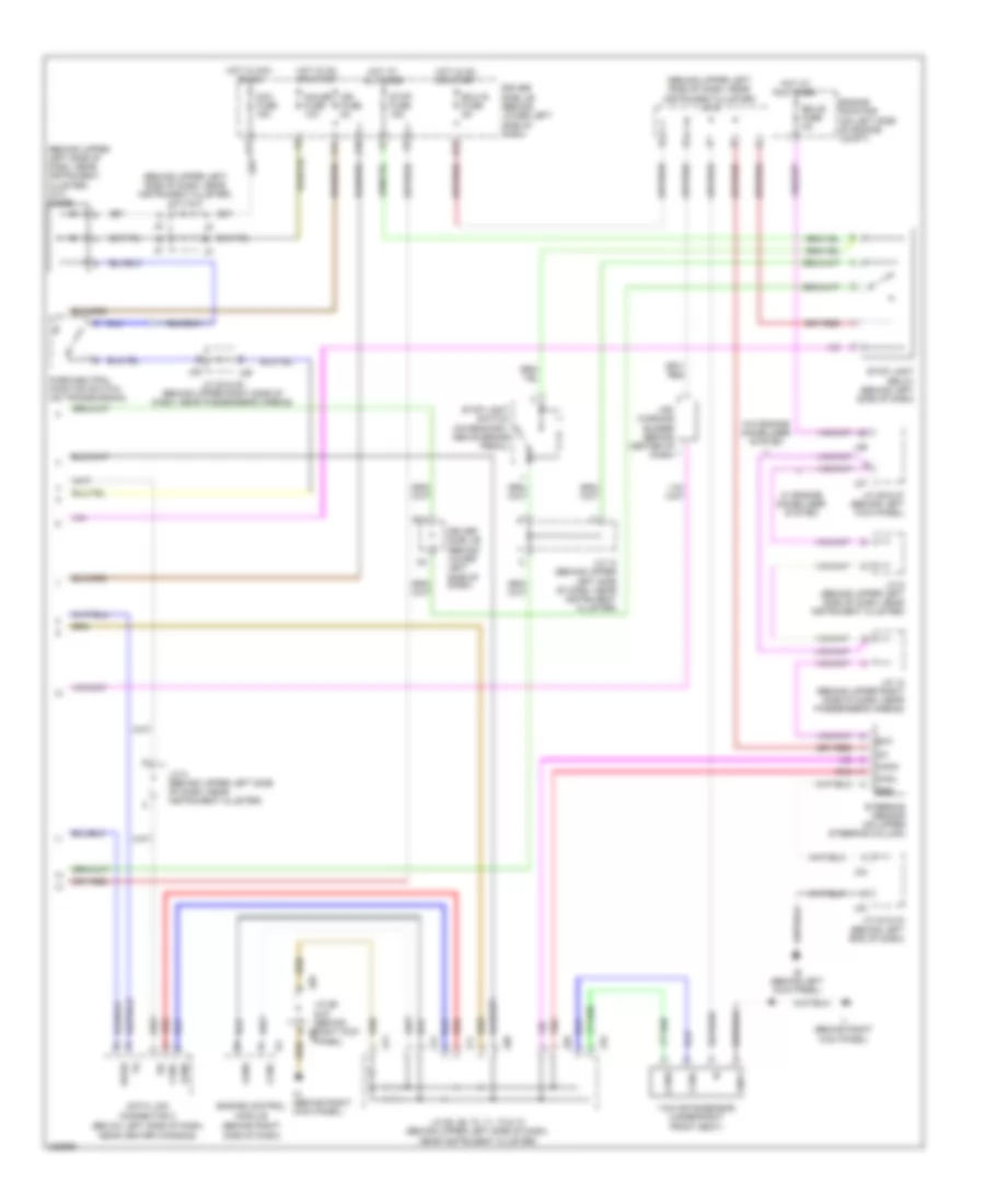
Anti-lock Brakes Wiring Diagram, Access/Standard Cab withVSC (2 of 2) for Toyota Tundra Limited 2006
List of elements for Anti-lock Brakes Wiring Diagram, Access/Standard Cab withVSC (2 of 2) for Toyota Tundra Limited 2006:
- (behind upper left side of dash, near instrument cluster) (a/t) diode
- (behind upper left side of dash, near instrument cluster) j/c 8 & 9
- (behind upper left side of dash, near instrument cluster) j/c 9
- Acc fuse 15a
- Bat
- Canh
- Canl
- Data link connector 3 (below left side of dash, near center console)
- Driver side j/b (behind lower left side of dash)
- E12
- Ecu-b fuse 5a
- Ecu-ig fuse 5a
- Engine control module (behind right side of dash)
- Engine room r/b (on left side of engine compt)
- Ess
- F10
- F11
- G11
- G13
- Gauge fuse 10a
- Gnd1
- Hot at all times
- Hot in acc or on
- Hot in on or start
- Ie (behind left kick panel)
- Ig1
- Ign fuse 5a
- Ih (behind right kick panel)
- Ii (behind right
- J/c 10 (behind upper left side of dash, near instrument cluster)
- J/c 12 (behind upper right side of dash, near passenger's airbag)
- J/c 23 & 24 (behind left end of dash)
- J/c 26 & 27 (behind left kick panel)
- J/c 28 & 29 (behind upper right side of dash, near passenger's airbag)
- J/c 66 & 67 (behind right kick panel)
- J/c 68, 69, 70, 71, 72 & 73 (behind upper left side of dash, near instrument cluster)
- J/c 8 (behind upper left side of dash, near instrument cluster)
- J/c 9 (behind upper left side of dash, near instrument cluster)
- J23
- J24
- J26
- J27
- J28
- J29
- J66
- J67
- J68
- J69
- J70
- J71
- J72
- J73
- Kick panel)
- Park/neutral position switch (on transmission)
- Pnk
- Red
- Sil
- Steering sensor (on upper steering column)
- Stop fuse 15a
- Stop light relay (behind left side of dash)
- Stop light switch (on bracket, above brake pedal)
- Vsc warning buzzer (behind center of dash)
- W/ engine immobiliser system
- W/o engine immobiliser system
- Wfse
- Yaw rate sensor (under right front seat)
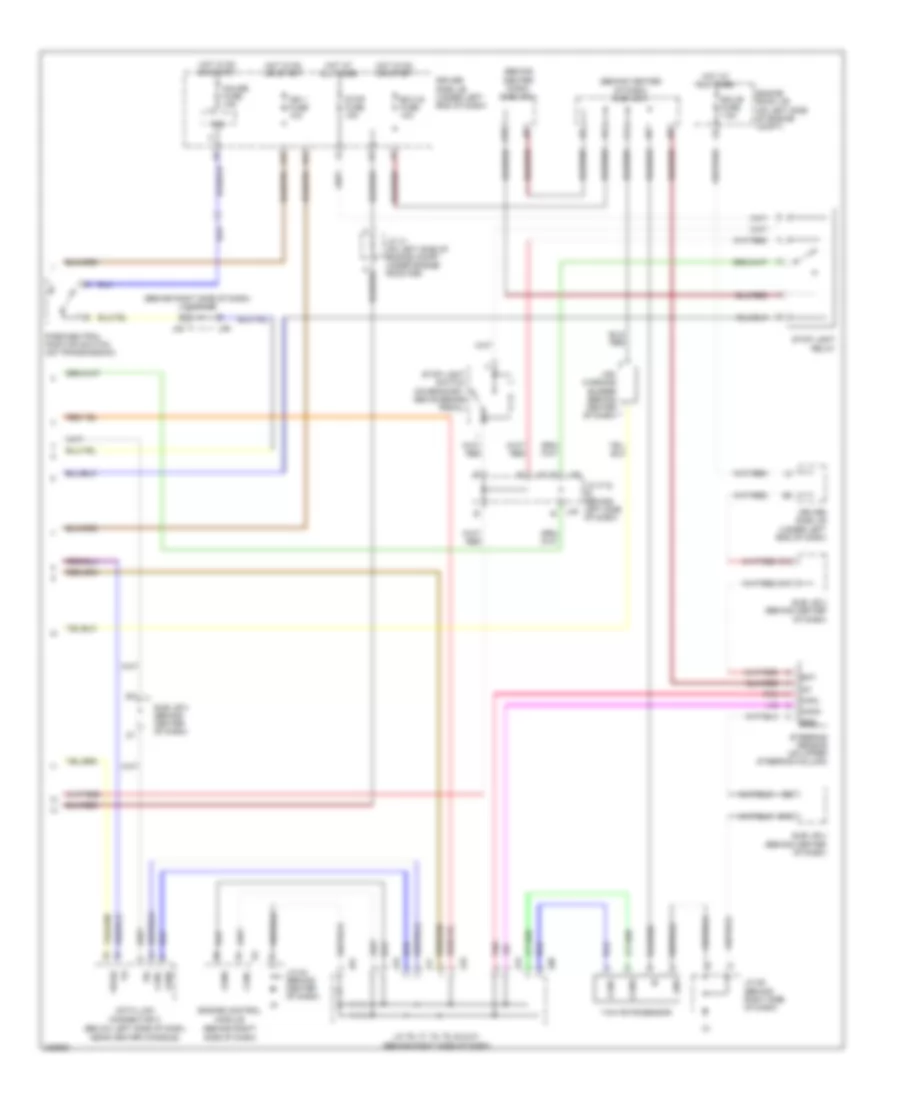
Anti-lock Brakes Wiring Diagram, Double Cab with VSC (1 of 2) for Toyota Tundra Limited 2006
List of elements for Anti-lock Brakes Wiring Diagram, Double Cab with VSC (1 of 2) for Toyota Tundra Limited 2006:
- (at left rear of engine compt) skid control ecu w/ actuator
- (behind right side of dash) j/c 75
- +bm1
- +bm2
- +bs
- A13
- Abs 1 fuse 40a
- Abs 2 fuse 30a
- Abs ind
- Active circuit
- Auto lsd ind
- Brake fluid level warning switch (on brake fluid reservoir)
- Brake ind
- Brl
- C11
- C12
- Canh
- Canl
- Combination meter
- Csw
- D/g
- Driver side j/b (under left end of dash)
- Em (at right front of engine compt)
- Exi
- Exi4
- Fl+
- Fl-
- Fr+
- Fr-
- Fusible link block (on left side of engine compt)
- Gnd1
- Gnd2
- Gnd3
- Hot at all times
- I24
- Ig1
- Ig2
- Ind
- Infr
- Integration control & panel
- J/c 45 (behind left side of dash)
- J/c 58 (behind right side of dash)
- K12
- Lbl
- Left
- Left front abs speed sensor (at left front steering knuckle assembly)
- Parking brake switch (on base of park brake pedal bracket, near kick panel)
- Pkb
- Pnk
- Rear abs speed sensor (on left side of rear axle)
- Red
- Right
- Right front abs speed sensor (at right front steering knuckle assembly)
- Rl+
- Rl-
- Rr+
- Rr-
- S29
- S30
- Slip ind
- Sp1
- Stp
- Stp2
- Stpo
- Sub j/b 3 (behind center of dash)
- Transmissions system
- Vsc off ind
- Vsc trac ind
- Vscw
- Wfse
Anti-lock Brakes Wiring Diagram, Double Cab with VSC (2 of 2) for Toyota Tundra Limited 2006
List of elements for Anti-lock Brakes Wiring Diagram, Double Cab with VSC (2 of 2) for Toyota Tundra Limited 2006:
- (behind center dash) sub j/b 4
- (behind center of dash) sub j/b 3
- (behind right side of dash) j/c 28 & 29
- A18
- Bat
- Canh
- Canl
- D10
- Data link connector 3 (below left side of dash, near center console)
- Driver side j/b (under left end of dash)
- E10
- E17
- Ecu-b fuse 7.5a
- Ecu-ig fuse 10a
- Engine control module (behind right side of dash)
- Engine room j/b (on left side of engine compt)
- Ess
- Gauge fuse 15a
- Gnd
- H11
- Hot at all times
- Hot in on or start
- Ig1
- Ign 1 fuse 10a
- Ipo
- J/c 31 (on left side of engine compt, under engine room r/b)
- J/c 47 & (behind left side of dash)
- J/c 54 (behind center of dash)
- J/c 58 (behind right side of dash)
- J/c 76, 77, 78, 79, 80 & 81 (behind right side of dash)
- J28
- J29
- J47
- J48
- J76
- J77
- J78
- J79
- J80
- J81
- Park/neutral position switch (on transmission)
- Pnk
- Sil
- Steering sensor (on upper steering column)
- Stop fuse 15a
- Stop light relay
- Stop light switch (on bracket, above brake pedal)
- Sub j/b 3 (behind center of dash)
- Sub j/b 4 (behind center of dash)
- Vsc warning buzzer (behind center of dash)
- Wfse
- Yaw rate sensor
Anti-lock Brakes Wiring Diagram, Double Cab without VSC for Toyota Tundra Limited 2006
List of elements for Anti-lock Brakes Wiring Diagram, Double Cab without VSC for Toyota Tundra Limited 2006:
- (behind left side of dash) j/c 45
- +bm
- +bs
- Abs 1 fuse 60a
- Abs 2 fuse 30a
- Abs actuator w/ ecu (in right rear corner of engine compt)
- Abs deceleration sensor (front passenger seat)
- Abs ind
- Active circuit
- Alt fuse 140a
- C11
- C12
- Combination meter
- Control circuit
- D/g
- Data link connector 3 (below left side of dash, near center console)
- Driver side j/b (under left end of dash)
- Ecu ig fuse 10a
- Exi
- Exi4
- F15
- Fl+
- Fl-
- Fr+
- Fr-
- Fusible link block (on left side of engine compt)
- G j29
- Gauge fuse 15a
- Ggnd
- Gl1
- Gnd1
- Gnd2
- H11
- Hot at all times
- Hot in on or start
- Ig1
- Ign1 fuse 10a
- Ipo
- J/c 28 & 29 (behind right side of dash)
- J/c 31 (on left side of engine compt, under engine room r/b)
- J/c 47 (behind left side of dash)
- J/c 48 (behind left side of dash)
- J/c 58 (behind right side of dash)
- J28
- K10
- Left
- Left front abs speed sensor (at left front steering knuckle assembly)
- Nca
- Park/neutral position switch (on transmission)
- Pnk
- Rear abs speed sensor (on left side of rear axle)
- Red
- Right
- Right front abs speed sensor (at right front steering knuckle assembly)
- Rl+
- Rl-
- Rr+
- Sil
- Spi
- Stop fuse 15a
- Stop light switch (on bracket, above brake pedal)
- Stp
- Sub j/b 3 (behind center of dash)
- Transmissions system
- Vgs