ANTI-THEFT
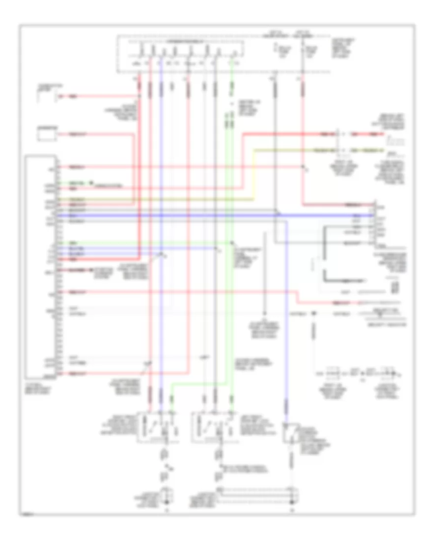
Anti-theft Wiring Diagram for Toyota Matrix XRS 2004
List of elements for Anti-theft Wiring Diagram for Toyota Matrix XRS 2004:
- (behind left side of dash) daytime running light relay
- (in dash harness, behind instrument panel j/b)
- (in instrument panel harness, behind right end of dash)
- (w/ power window) (w/o power window)
- +b1
- A11
- A19
- B2 b1
- Center j/b (behind left side of dash)
- Combination meter
- Cty
- Dcty
- Detection
- Dmlp
- Dswd
- Ecu-b fuse 10a
- Ecu-ig fuse 10a
- Ehw
- Glass breakage sensor ecu (behind upper right end of dash)
- Gmic
- Gnd
- Head
- Horn
- Horns system
- Hot at all times
- Hot in on or start
- Hzad
- I1 (in instrument panel harness, at left side of dash)
- I10
- I10 (in instrument panel harness, behind right end of dash)
- I12
- I2 (in dash harness, behind instrument panel j/b)
- Ind
- Instrument panel j/b (behind left side of dash)
- Integration relay
- Iout
- Irsg
- Junction connector 2 (behind left side of dash)
- Junction connector 7 (at right kick panel)
- Junction connector 7 (at right kick panel)
- Ksw
- Left front door key lock & unlock switch, door unlock detection switch
- Lock
- Lswd
- Lswp
- Mic
- Micro- phone
- Nca
- Prcty
- Red
- Rheostat
- Right front door key lock & unlock switch, door unlock detection switch
- Right j/b (behind upper right side of dash)
- S+b
- Security ind
- Security indicator
- Srly
- Starting/ charging system
- Trig
- Turn signal flasher relay (behind left side of dash, on instrument panel j/b)
- Tvip ecu (behind right end of dash)
- Ul2
- Ul3
- Unlk
- Unlock warning switch (on steering column, behind ignition key cylinder)
 English