BODY CONTROL MODULES
Body ECU Wiring Diagram (1 of 2) for Toyota Tundra SR5 2009

List of elements for Body ECU Wiring Diagram (1 of 2) for Toyota Tundra SR5 2009:
- Acc
- Acc fuse 7.5a
- Act+
- Act-
- Altb
- B11
- B13
- B16
- B18
- Becu
- C23
- C24
- Can
- Canh
- Canl
- Cann
- Canp
- Cglp
- Cgnd
- Cgsw
- Cltb
- Clte
- Clts
- D13
- D14
- D40
- D41
- D42
- D49
- D51
- D52
- D53
- D62
- Dim
- Door locks & anti-theft systems
- Dr/lck fuse 25a
- Driver side j/b (left side of dash)
- Drl
- Ecu-b1 fuse 7.5a
- Ecu-ig 2 fuse 7.5a
- Engine room r/b (left side of engine compartment)
- Exterior lights system
- Ffog
- Gnd1
- Gnd2
- Haz
- Head
- Headlights system
- Headlights, anti-lock brakes & instrument cluster systems
- Horn
- Horns system
- Hot at all times
- Hot in on or acc
- Hot in on or start
- Hrly
- Ile
- Interior lights system
- J/c j89, j90, j91, j95 & j97 (w/ seat position memory) (floor shift: left side of dash)
- J1 (column shift: left side of dash) (floor shift: left kick panel)
- J89
- J90
- J91
- J95
- J97
- Lcty
- Left front power seat control ecu & switch (separate seat: driver's seat)
- Lin2
- Lswl
- Lswp
- Lswr
- Main body ecu (left side of dash)
- Memory systems
- Multiplex tilt & telescopic ecu (floor shift: left side of dash)
- Outer mirror control ecu (driver's door)
- Pcty
- Pkb
- Pnk
- Power tops system
- Prg
- Pwr relay
- Pws
- Rda
- Red
- Ret
- Rrcy
- Trly
- Ul1
- Ul2
- Z10
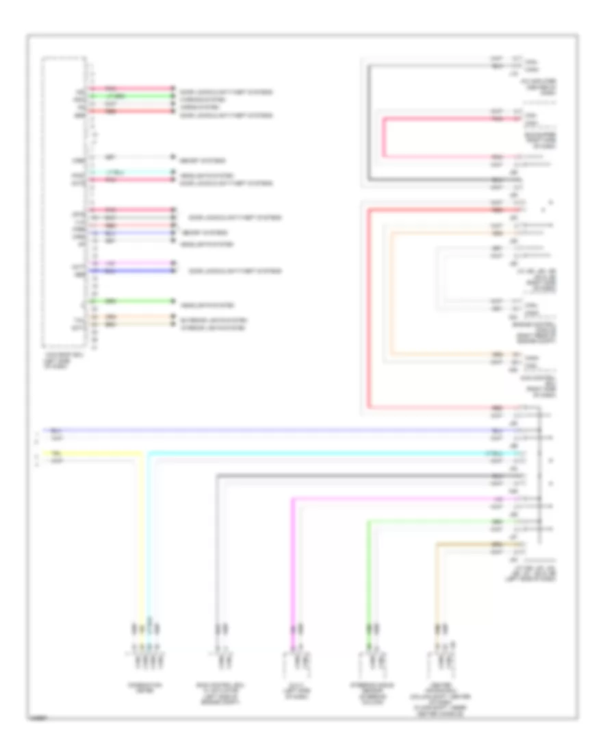
Body ECU Wiring Diagram (2 of 2) for Toyota Tundra SR5 2009
List of elements for Body ECU Wiring Diagram (2 of 2) for Toyota Tundra SR5 2009:
- (left side of dash)
- 4wd control ecu (right side of dash)
- A/c amplifier (center of dash)
- A24
- A25
- A46
- Actd
- Bus buffer (right side of dash)
- Bzr
- Can+
- Can-
- Canh
- Canl
- Center air bag ecu (column shift: center of dash) (floor shift: under center console)
- Combination meter
- Dcty
- Dlc 3 (left side of dash)
- Door locks & anti-theft systems
- Engine control module (right rear of engine compt)
- Exterior lights system
- Ffgo
- Gbs
- Hcty
- Headlights system
- Horns system
- Ind
- Interior lights system
- J/c a46, j83, j84, j86, j87, j94 & j96 (left side of dash)
- J/c j85, j88, j92 j93 & j98 (right side of dash)
- J19
- J46
- J83
- J84
- J85
- J86
- J87
- J88
- J92
- J93
- J94
- J96
- J98
- Ksw
- Lswd
- Main body ecu
- Memory systems
- Mirb
- Mire
- Mirs
- Pnk
- Red
- Skid control ecu w/ actuator (left side of engine compt)
- Steering angle sensor (steering column)
- Tail
- Ul3
- Warning system
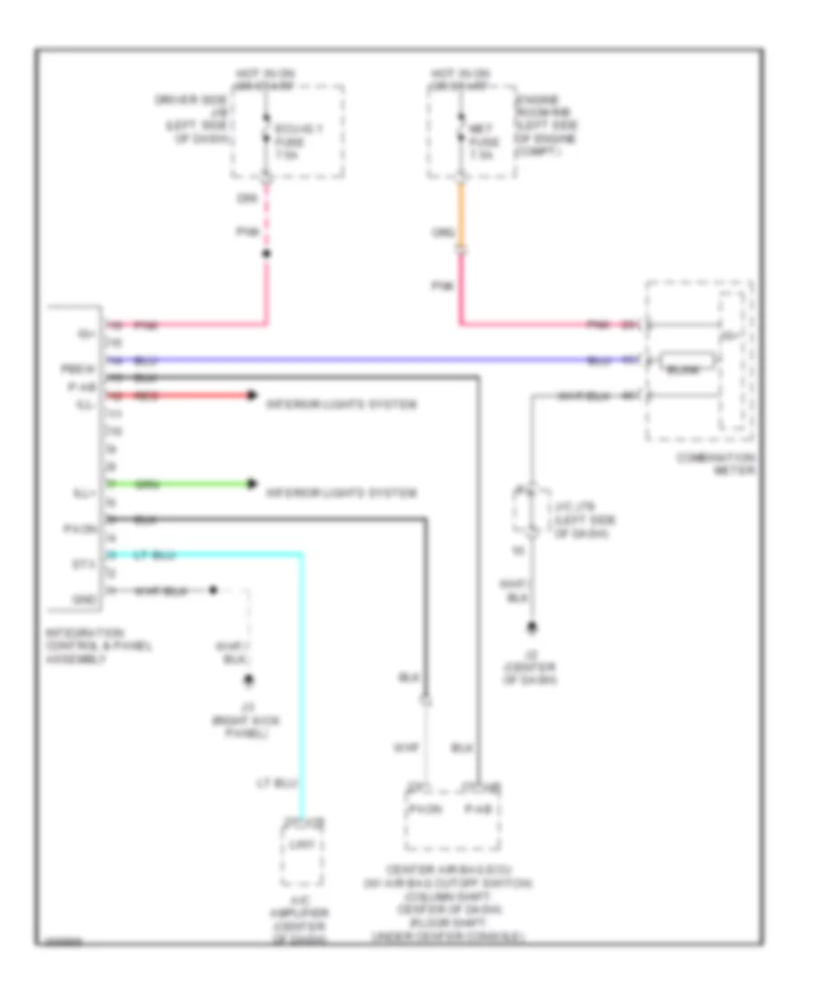
Integration Control and Panel Wiring Diagram for Toyota Tundra SR5 2009
List of elements for Integration Control and Panel Wiring Diagram for Toyota Tundra SR5 2009:
- A/c amplifier (center of dash)
- Blink
- Center air bag ecu (w/ air bag cutoff switch) (column shift: center of dash) (floor shift: under center console)
- Combination meter
- D56
- Driver side j/b (left side of dash)
- Ecu-ig 1 fuse 7.5a
- Engine room r/b (left side of engine compt)
- Gnd
- Hot in on or start
- Ig+
- Ill+
- Ill-
- Integration control & panel assembly
- Interior lights system
- J/c j78 (left side of dash)
- J19
- J2 (center of dash)
- J3 (right kick panel)
- J46
- Lin1
- Met fuse 7.5a
- P-ab
- Paon
- Pbew
- Pnk
- Red
- Stx