CRUISE CONTROL
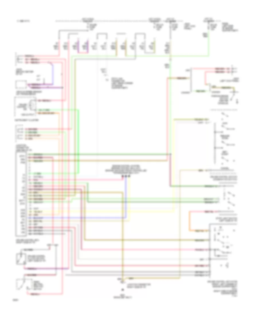
Cruise Control Wiring Diagram for Toyota Celica GT 1994
List of elements for Cruise Control Wiring Diagram for Toyota Celica GT 1994:
- 1995 vftc c
- A/t
- B11
- Batt
- Canada
- Cancel
- Ccs
- Cms
- Cruise control actuator (front left corner of engine compartment) (2.2l) (right side of engine compartment) (1.8l)
- Cruise control clutch switch (left side of i/p)
- Cruise control ecu (right side of i/p)
- Cruise control ind
- Cruise control switch (combination switch)
- Data link connector (left rear corner of engine compartment)
- Ect
- Ecu-b fuse 15a
- Ecu-ig fuse 15a
- Engine control system (engine control ecu) (m/t) (engine and electronic controlled transmission ecu) (a/t)
- G201 (r/b #4 set bolt)
- Gauge fuse 10a
- Gnd
- Hot at all times
- Hot in run and acc
- Idl
- Instrument cluster
- J/b #1 (left kick panel)
- J/b #3 (behind center of i/p)
- Junction connector (center of i/p)
- Junction connector (right side of i/p)
- K10
- K13
- M/t
- Main
- N&c
- Park/ neutral position switch
- Parking brake switch (center console)
- Pkb
- Pnk
- R/b #2 (left side of engine compartment)
- Resume/ accel
- Set/ coast
- Spd
- Stop fuse 15a
- Stop light switch (left side of i/p)
- Stp+
- Stp-
- Usa
- Vehicle speed sensor (on transmission)
- Vr1
- Vr2
- Vr3
- Vss output
 English