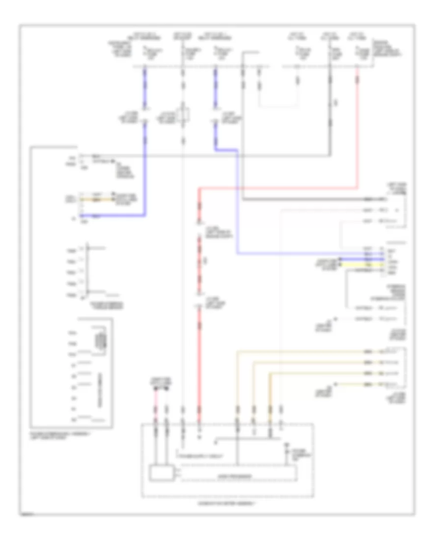
ELECTRONIC POWER STEERING
Electronic Power Steering Wiring Diagram for Toyota Sienna LE 2013
List of elements for Electronic Power Steering Wiring Diagram for Toyota Sienna LE 2013:
- (left side of dash) j/c d98
- A35
- A55
- Ad1
- Ad4
- Bat
- Can l can h
- Canh
- Canl
- Combination meter assembly
- Computer data lines system
- D35
- D36
- D38
- D5 (under center console)
- D6 (center of dash)
- D7 (center of dash)
- Dome fuse 7.5a
- Ecu-b fuse 10a
- Ecu-ig 1 fuse 10a
- Ecu-ig 2 fuse 10a
- Engine room r/b (left side of engine compt)
- Eps fuse 60a
- Ess
- F39
- Gauge 2 fuse 7.5a
- Hot at all times
- Hot in on or start
- Hot w/ ig1 1 relay energized
- Hot w/ ig1 2 relay energized
- Ig+
- Ig2
- Instrument panel j/b (left side of dash)
- J/c a52 (left side of engine compt)
- J/c d100 (left side of dash)
- J/c d105 (center of dash)
- J/c d96 (left side of dash)
- J/c d97 (left side of dash)
- J/c d99 (left side of dash)
- Lcl-
- Mgnd
- Micro processor
- Pgnd
- Pha
- Phb
- Phc
- Pig
- Pnk
- Power steering ecu assembly (left side of dash)
- Power steering ind
- Power steering motor
- Power steering torque sensor
- Red
- Resolver sensor
- Steering sensor (inside steering column)
- Trq1
- Trq2
- Trqf
- Trqg
- Trqv
 English