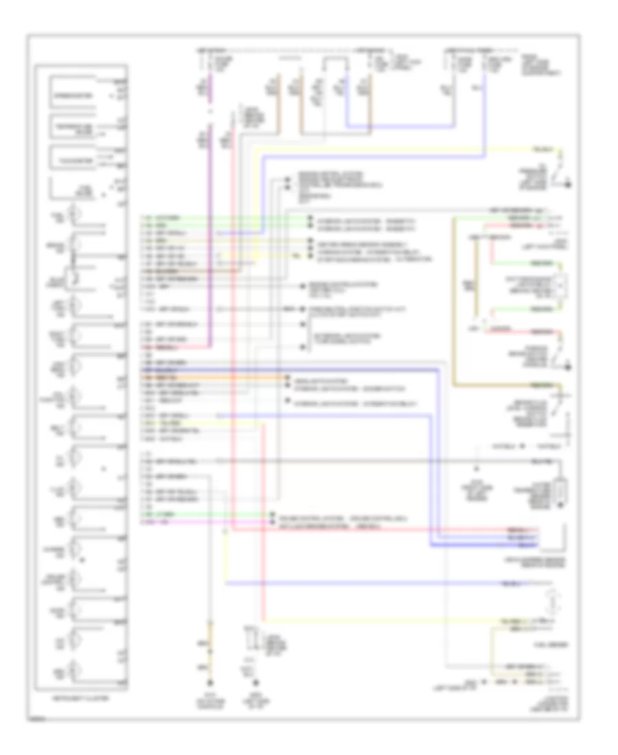
INSTRUMENT CLUSTER
Instrument Cluster Wiring Diagram for Toyota Celica GT 1994
List of elements for Instrument Cluster Wiring Diagram for Toyota Celica GT 1994:
- (abs ecu)
- (alternator)
- (cruise control ecu)
- (dimmer switch)
- (integration relay)
- (rheostat)
- A10
- A11
- A12
- A13
- Abs ind
- Anti-lock brakes system
- B10
- B11
- B12
- B13
- B14
- B15
- B16
- Belt ind
- Brake fluid level warning switch (brake fluid reservoir)
- Brake ind
- Bulb check
- C10
- C14
- Canada
- Center airbag sensor assembly
- Charge ind
- Cruise control ind
- Cruise control system
- Daytime running lights relay (behind center of i/p)
- Dome fuse 10a
- Door ind
- Engine control system (engine and electronic controlled transmission ecu) (a/t) (engine ecu) (m/t)
- Engine controls system (igniter) (2.2l) (iia) (1.8l)
- Exterior lights system (turn signal switch)
- Fuel gauge
- Fuel ind
- Fuel sender
- G100 (front side of left fender)
- G131 (on intake manifold)
- G202 (left side of i/p)
- Gauge fuse 10a
- Headlights system
- High beam ind
- Hot at all times
- Hot in run
- Ign fuse 7.5a
- Illum ind
- Instrument cluster
- Interior lights system
- J/b #1 (left kick panel)
- J/b #3 (behind center of i/p)
- Junction connector (center of i/p)
- Left turn ind
- Mal- function ind
- O/d ind
- Oil ind
- Oil pressure switch (left side of engine)
- Park/neutral position switch (a/t) clutch start switch (m/t)
- Parking brake switch (center console)
- R/b #2 (left side of engine compartment)
- Right turn ind
- Speedometer
- Srs ind
- Srs wrn fuse 7.5a
- Starting/charging system
- Tachometer
- Temperature gauge
- Usa
- Vehicle speed sensor (rear of engine)
- Warning system
- Water temperature sender (rear of engine)
 English