INTERIOR LIGHTS
Courtesy Lamps Wiring Diagram for Toyota Celica GT 1994

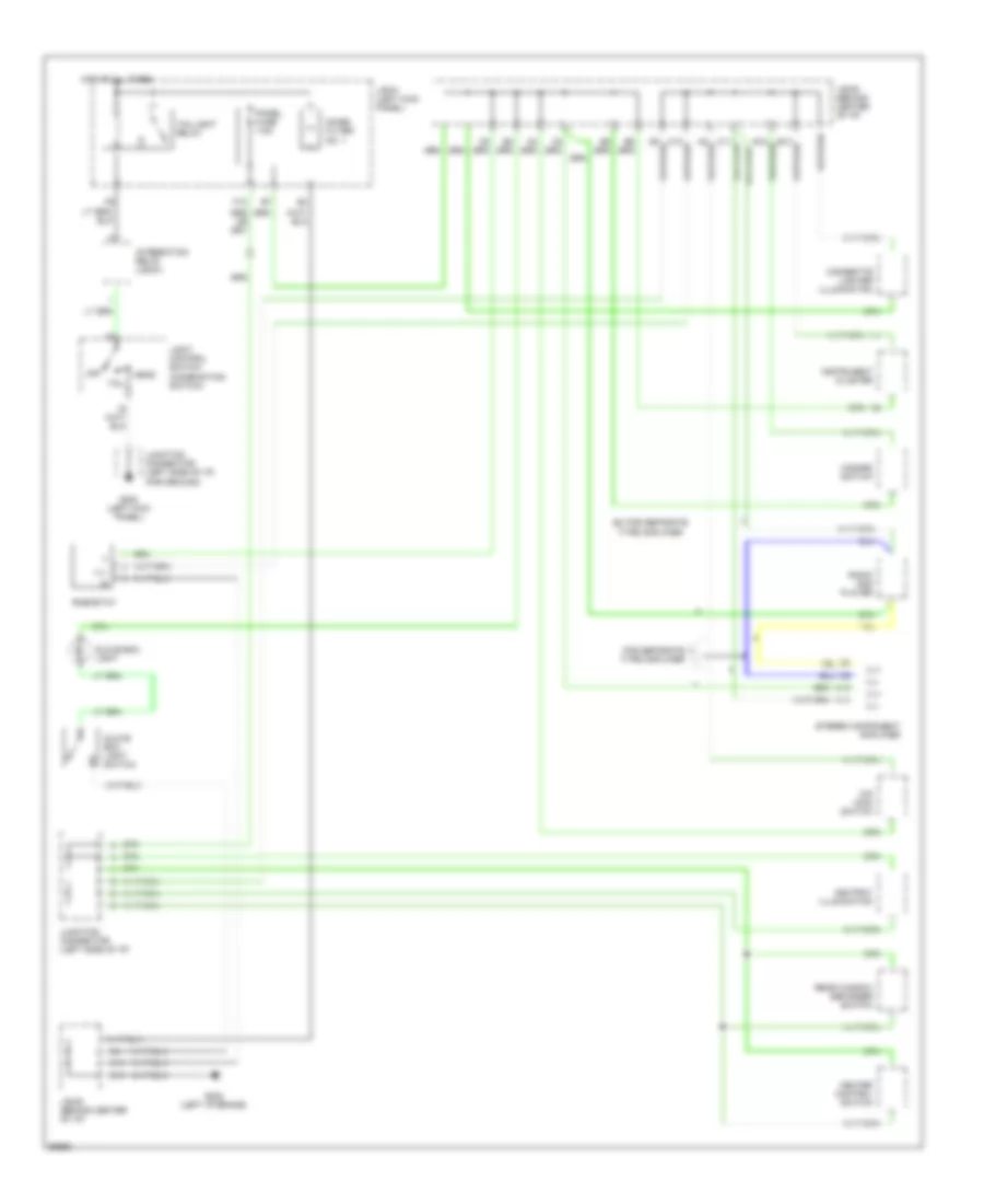
List of elements for Courtesy Lamps Wiring Diagram for Toyota Celica GT 1994:
- B10
- B11
- C14
- Coupe
- D11
- Dcty
- Diode (left kick panel) (for door courtesy light)
- Diode (left kick panel) (for luggage compt light)
- Dome fuse 10a
- Door
- Door open ind
- F10
- G202 (left i/p brace)
- G203 (r/b #4 set bolt)
- H10
- Hot at all times
- Ignition key cylinder switch
- Instrument cluster
- Integration relay
- J/b #1 (left kick panel)
- J/b #3 (behind center of i/p)
- Junction connector (left side of i/p) (for ground)
- Left
- Left door courtesy light
- Left door courtesy switch
- Liftback
- Luggage compartment light
- Luggage compartment light switch
- Off
- Pcty
- Personal light (w/ moonroof)
- Personal light (w/o moonroof)
- R/b #2 (left side of engine compartment)
- Right
- Right door courtesy light
- Right door courtesy switch
- W/ moonroof
- W/o moonroof
Instrument Illumination Wiring Diagram for Toyota Celica GT 1994
List of elements for Instrument Illumination Wiring Diagram for Toyota Celica GT 1994:
- A13
- A14
- Ashtray illumination
- C13
- C14
- Cigarette lighter illumination
- Ex for separate type amplifier
- F12
- For separate type amplifier
- G200 (left kick panel)
- G202 (left i/p brace)
- Glove box light
- Glove box light switch
- Hazard switch
- Head
- Heater control switch
- Hot at all times
- Ill+
- Ill-
- Instrument cluster
- Integration relay (j/b #1)
- J/b #1 (left kick panel)
- J/b #3 (behind center of i/p)
- Junction connector (left side of i/p)
- Junction connector (left side of i/p) (for ground)
- Light control switch (combination switch)
- Noise filter no. 1
- O/d main switch
- Off
- Panel fuse 7.5a
- Radio and player
- Rear window defogger switch
- Rheostat
- Stereo component amplifier
- Tail
- Taillight relay