STARTING/CHARGING
Charging Wiring Diagram for Toyota Celica GT 2000

List of elements for Charging Wiring Diagram for Toyota Celica GT 2000:
- Alt fuse 120a
- Alt-s fuse 7.5a
- B13
- Battery
- Battery ground
- C12
- C13
- Charge ind
- Combination meter
- Engine control module (left side of engine compt, forward of battery)
- Engine room j/b (left side of engine compt)
- G206 (behind center of dash)
- Generator
- Hot in run or start
- I12
- Instrument panel j/b (behind panel on right side of center console)
- Instrument panel j/b (right side of center console)
- M20
- Main fuse link (12-ga)
- Nca
- Warning fuse 5a
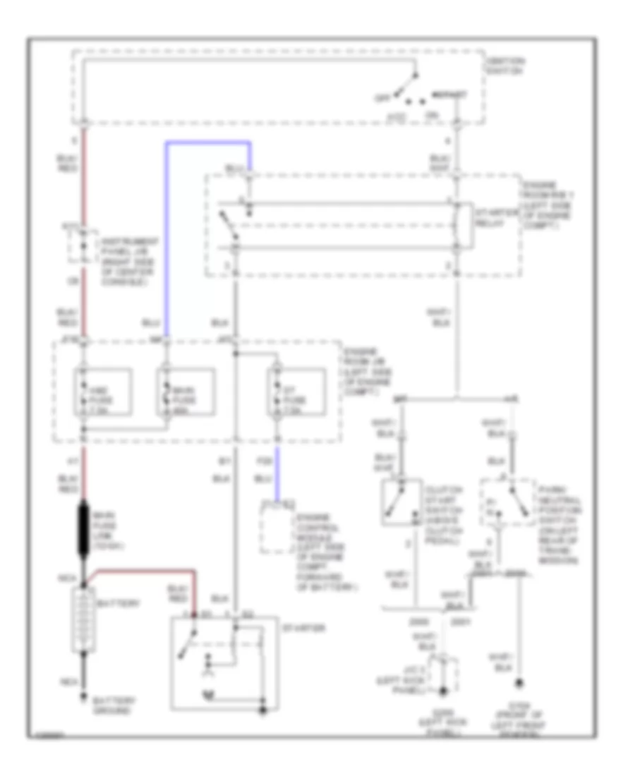
Starting Wiring Diagram for Toyota Celica GT 2000
List of elements for Starting Wiring Diagram for Toyota Celica GT 2000:
- A/t
- Acc
- Am2 fuse 7.5a
- Battery
- Battery ground
- Clutch start switch (above clutch pedal)
- Engine control module (left side of engine compt, forward of battery)
- Engine room j/b (left side of engine compt)
- Engine room r/b 1 (left side of engine compt)
- F16
- F20
- G104 (front of left front fender)
- G200 (left kick panel)
- Ignition switch
- Instrument panel j/b (right side of center console)
- J/c 3 (left kick panel)
- K11
- M/t
- Main fuse 40a
- Main fuse link (12-ga)
- Nca
- Off
- P/ n
- Park/ neutral position switch (on left rear of trans- mission)
- St fuse 7.5a
- Start
- Starter
- Starter relay