SUPPLEMENTAL RESTRAINTS
Supplemental Restraint Wiring Diagram for Toyota Celica GT 1994
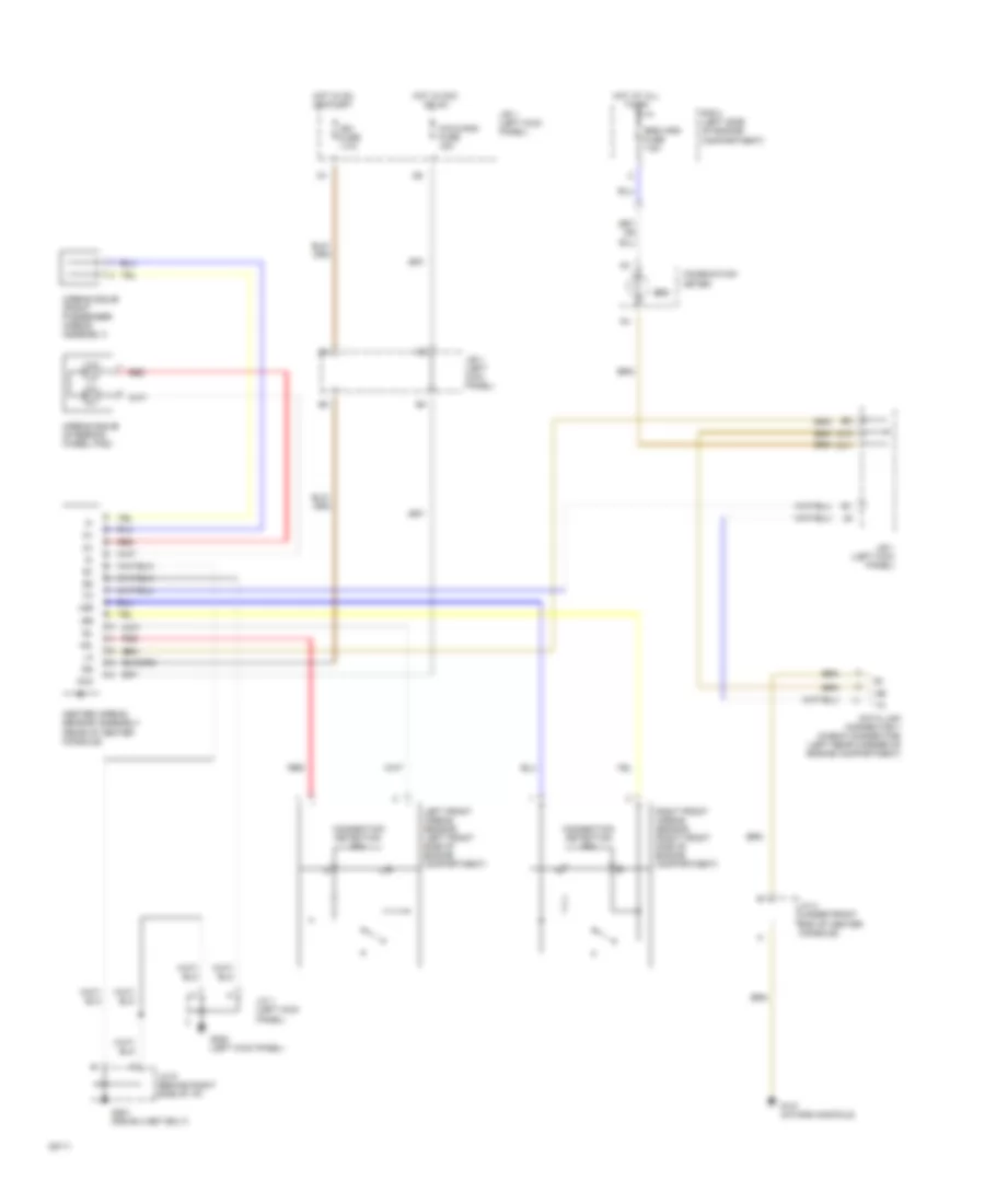
List of elements for Supplemental Restraint Wiring Diagram for Toyota Celica GT 1994:
- +sl
- +sr
- -sl
- -sr
- Acc
- Airbag squib (front passenger airbag assembly)
- Airbag squib (steering wheel pad)
- Center airbag sensor assembly (rear of center console)
- Cig & rad fuse 15a
- Combination meter
- Connection detection pin
- D10
- D11
- Data link connector 1 (check connector) (left rear corner of engine compartment)
- G131 (intake manifold)
- G200 (left kick panel)
- G201 (r/b n0.4 set bolt)
- Hot at all times
- Hot in acc or on
- Hot in on or start
- Ig2
- Ign fuse 7.5a
- J/b 1 (left kick panel)
- J/b 1 (left kick panel)
- J/c 1 (left kick panel)
- J/c 4 (under front end of center console)
- J/c 9 (behind right side of i/p)
- Left front airbag sensor (left front side of engine compartment)
- R/b 2 (left side of engine compartment)
- Red
- Right front airbag sensor (right front side of engine compartment)
- Srs
- Srs wrn fuse 7.5a
 English