TRANSMISSION
4.0L
4.0L, 4WD Wiring Diagram for Toyota Tundra Limited 2006

List of elements for 4.0L, 4WD Wiring Diagram for Toyota Tundra Limited 2006:
- (behind upper right side of dash)
- (pins 3-16 not used)
- (w/ vsc)
- (w/o vsc)
- 2-4
- 4hi ind
- 4lo ind
- 4wd
- 4wd control ecu (behind lower right side of dash)
- 4wd fuse 20a
- Abs actuator w/ ecu (in right rear corner of engine compt)
- Acc fuse 15a
- Add
- Add actuator (on left front of engine)
- Anti-lock brakes system
- C11
- C12
- Combination meter
- Detection
- Detection switch (transfer 4wd position) (4.7l: at left side of transmission)
- Detection switch (transfer l4 position) (4.7l: at rear of transmission)
- Diode (a/t) (behind upper left side of dash)
- Dl1
- Dl2
- Dm1
- Dm2
- Driver side j/b (behind lower left side of dash)
- Engine control module (behind right side of dash)
- Exi
- Exi4
- F10
- F20
- F21
- G j28
- G j29
- G11
- Gauge fuse 10a
- Gnd
- H-l
- Hot in on or acc
- Hot in on or start
- I24
- Ign fuse 5a
- Ind1
- Ind3
- Integration control & panel
- J/c 10 (behind upper left side of dash)
- J/c 12
- J/c 13 (behind right kick panel)
- J/c 28 & 29 (behind upper right side of dash)
- J/c 64
- J/c 66 & 67 (behind right kick panel)
- J/c 8 (behind upper left side of dash)
- J/c 9 (behind upper left side of dash)
- J28
- J29
- J66
- J67
- Park/neutral position switch (on transmission)
- Pnk
- Red
- S29
- Skid control ecu w/ actuator (at left rear of engine compt)
- Spd
- Speed control
- Switch
- Tl1
- Tl2
- Tm1
- Tm2
- Tm3
- Transfer shift actuator (4.7l: on transfer case)
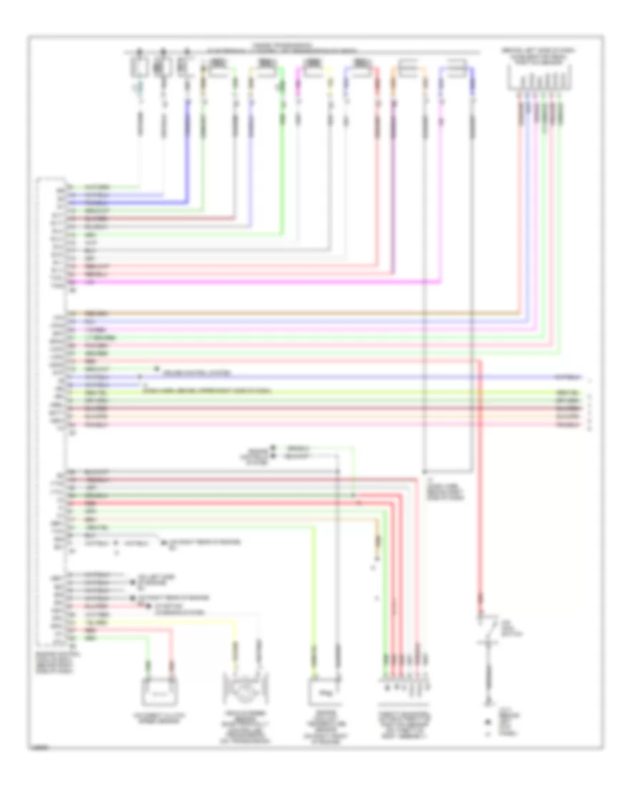
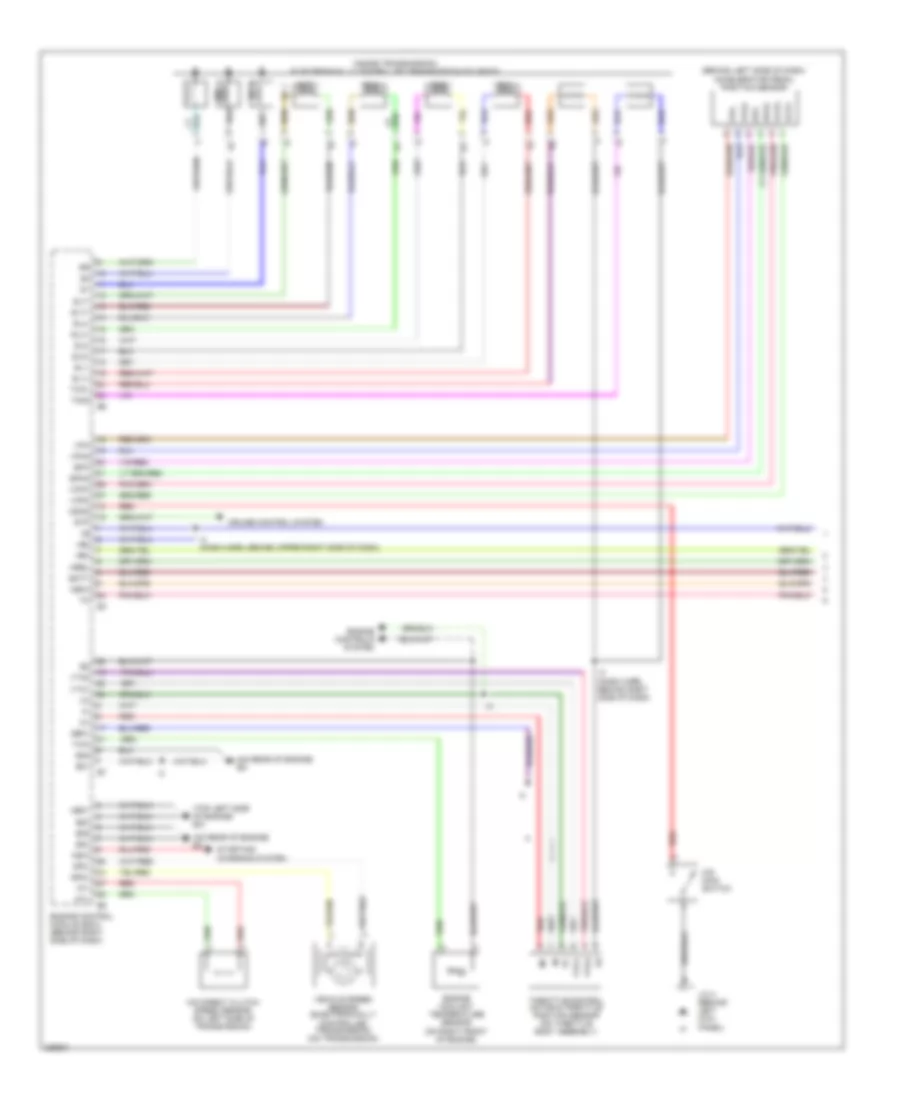
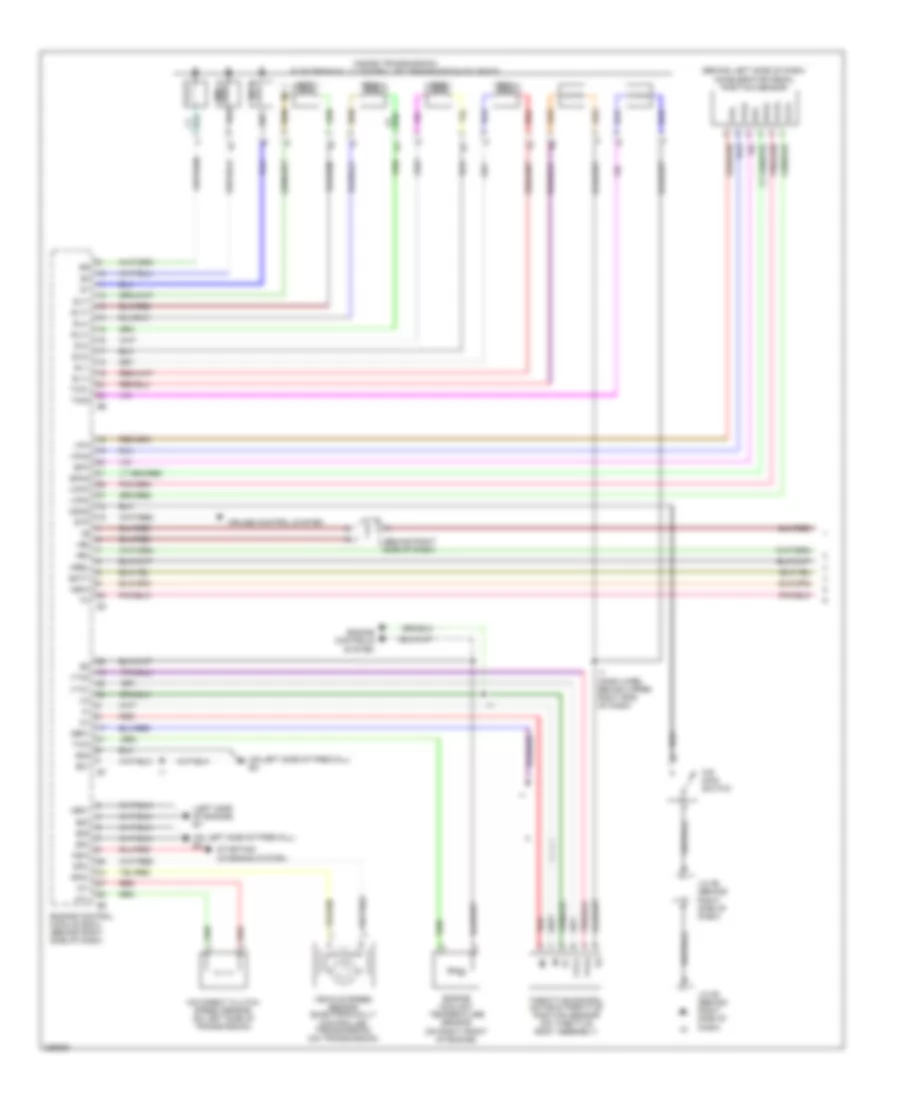
4.0L, A/T Wiring Diagram (1 of 3) for Toyota Tundra Limited 2006
List of elements for 4.0L, A/T Wiring Diagram (1 of 3) for Toyota Tundra Limited 2006:
- (behind left side of dash) accelerator pedal position sensor
- (inside transmission) electronically controlled transmission solenoid
- (on left side of engine) ev
- (on right rear of engine) eu
- +b2
- +bm
- Batt
- Cruise control system
- E01
- E02
- E03
- E04
- E05
- Engine control module (ecm) (behind right side of dash)
- Engine controls system
- Engine coolant temperature sensor (on right front of engine)
- Epa
- Epa2
- Ge01
- I3 (dash harn, behind right side of dash)
- I4 (dash harn, behind upper right side of dash)
- Igsw
- J/c 3 (behind left kick panel)
- Me01
- Mrel
- No 1
- No 2
- Nsw
- Nt+
- Nt-
- O/d direct clutch speed sensor
- O/d main switch
- Odms
- Red
- Sl1
- Sl1+
- Sl1-
- Sl2
- Sl2+
- Sl2-
- Slt
- Slt+
- Slt-
- Slu
- Slu+
- Slu-
- Sp2+
- Sp2-
- Starting/ charging system
- Stp
- Th02
- Tho1
- Throttle control motor & throttle position sensor (on throttle body assembly)
- Thw
- Vcp2
- Vcpa
- Vehicle speed sensor (electronically controlled transmission) (on transmission)
- Vpa
- Vpa2
- Vta1
- Vta2
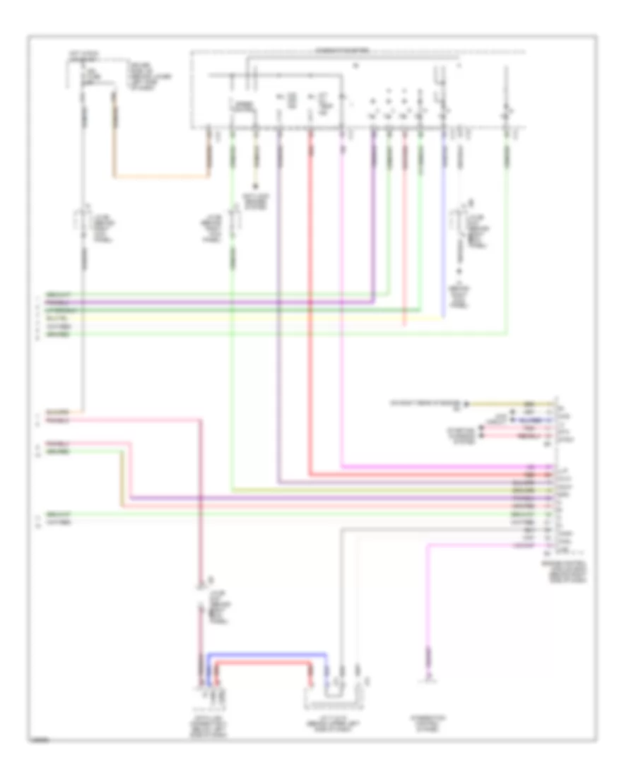
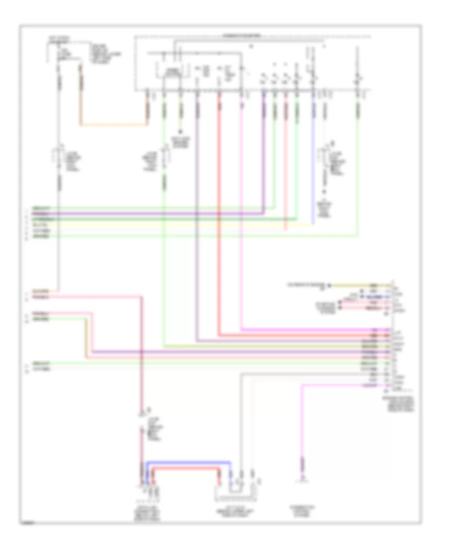
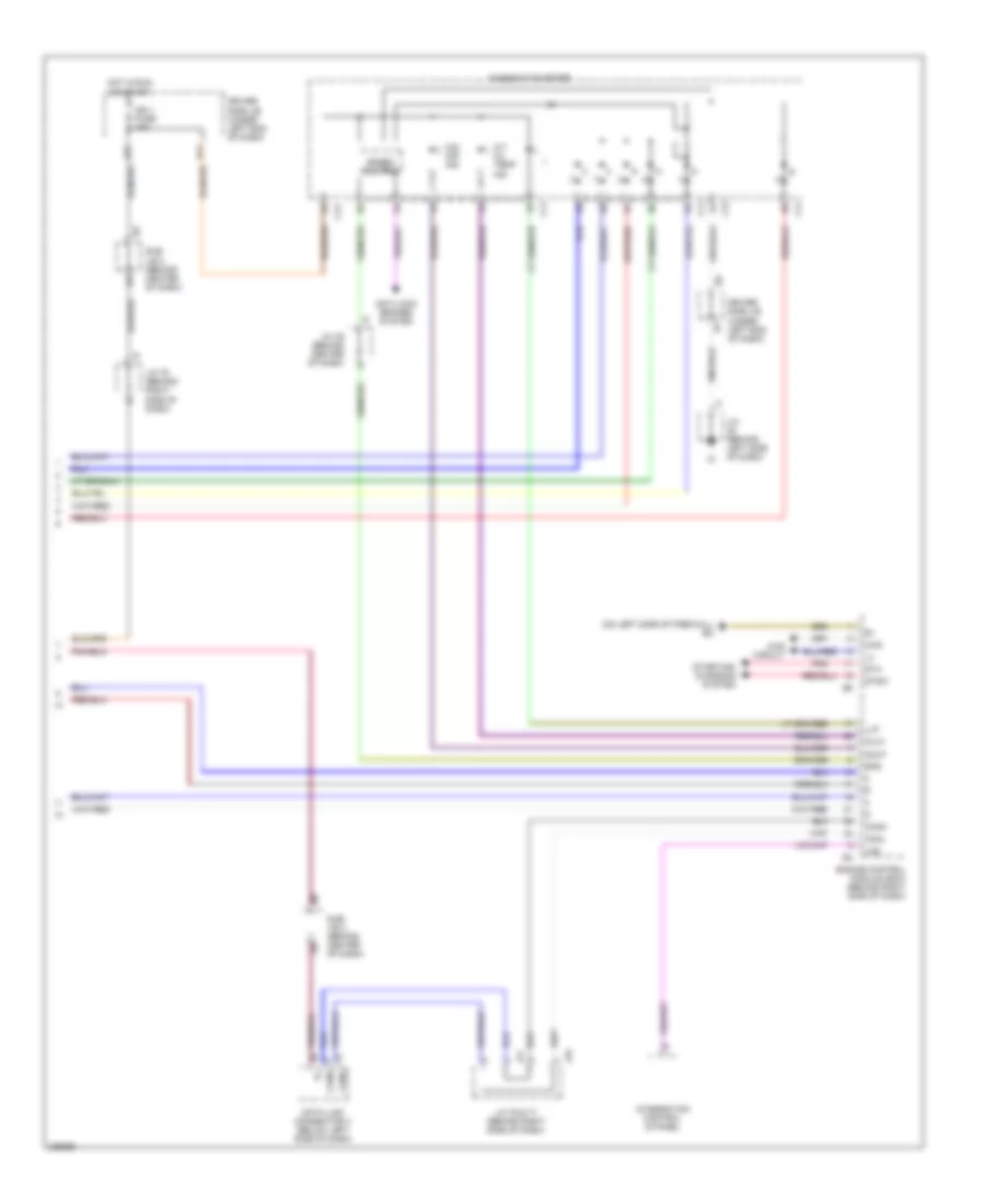
4.0L, A/T Wiring Diagram (2 of 3) for Toyota Tundra Limited 2006
List of elements for 4.0L, A/T Wiring Diagram (2 of 3) for Toyota Tundra Limited 2006:
- (behind upper left side of dash) diode (a/t)
- (on left side of engine compt) j/c 1
- A j28
- Acc fuse 15a
- B j28
- C j28
- D j28
- Driver side j/b (behind lower left side of dash)
- Ea (on left front fender)
- Efi 1 fuse 20a
- Efi relay
- Engine room r/b (on left side of engine compt)
- Etcs fuse 10a
- F j28
- G j28
- G11
- Gauge fuse 10a
- Hot at all times
- Hot in run or acc
- Hot in run or start
- J/c 18 (on left side of engine compt)
- J/c 26 & 27 (behind left j27 kick panel)
- J/c 28 & 29 (behind upper right side of dash)
- J/c 8 (behind upper left side of dash)
- J/c 9 (behind upper left side of dash)
- J26
- J29
- Park/neutral position switch (on transmission)
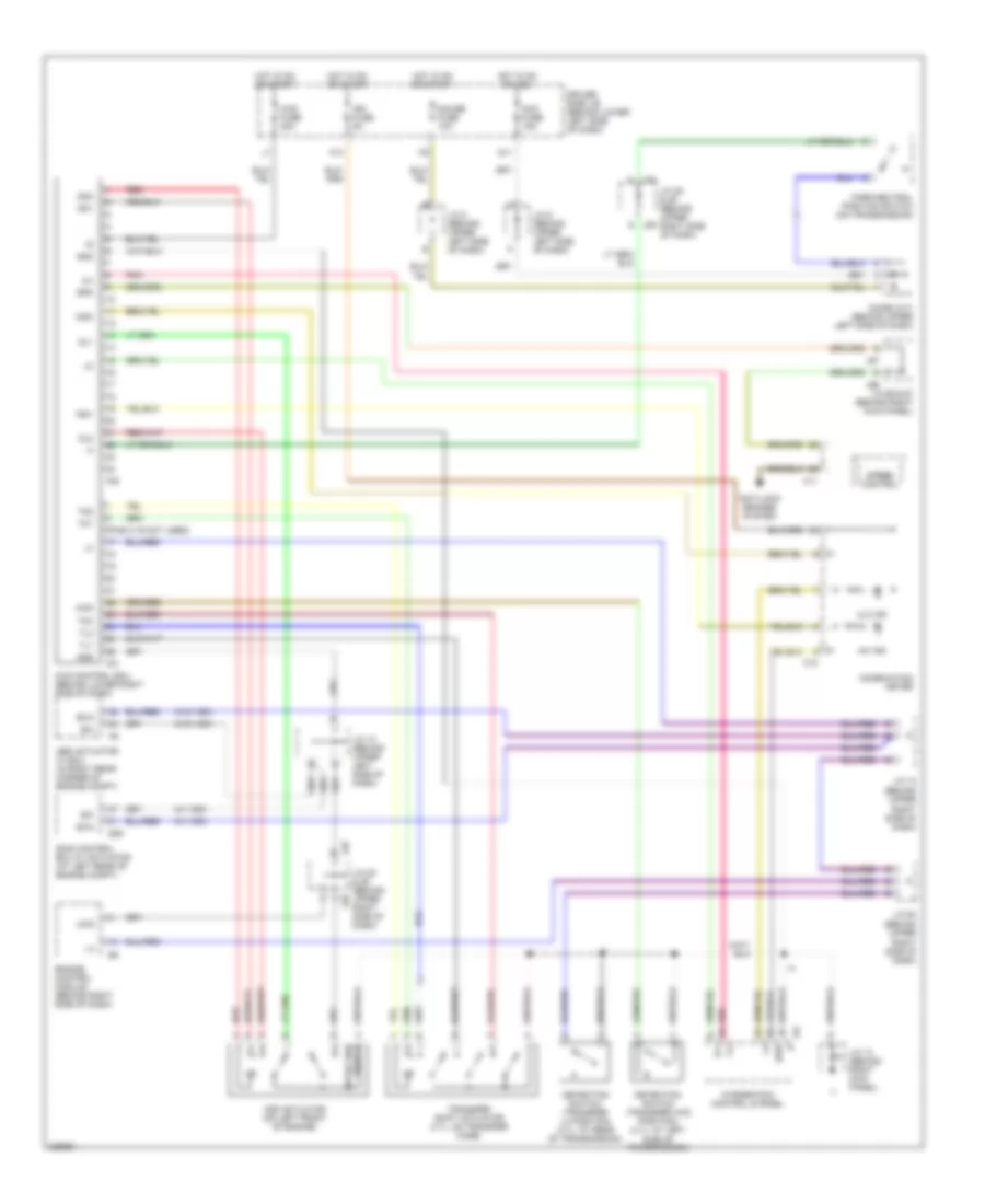
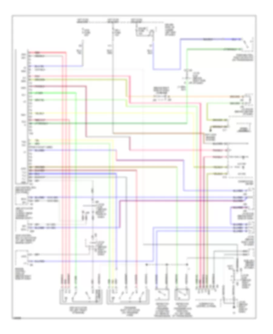
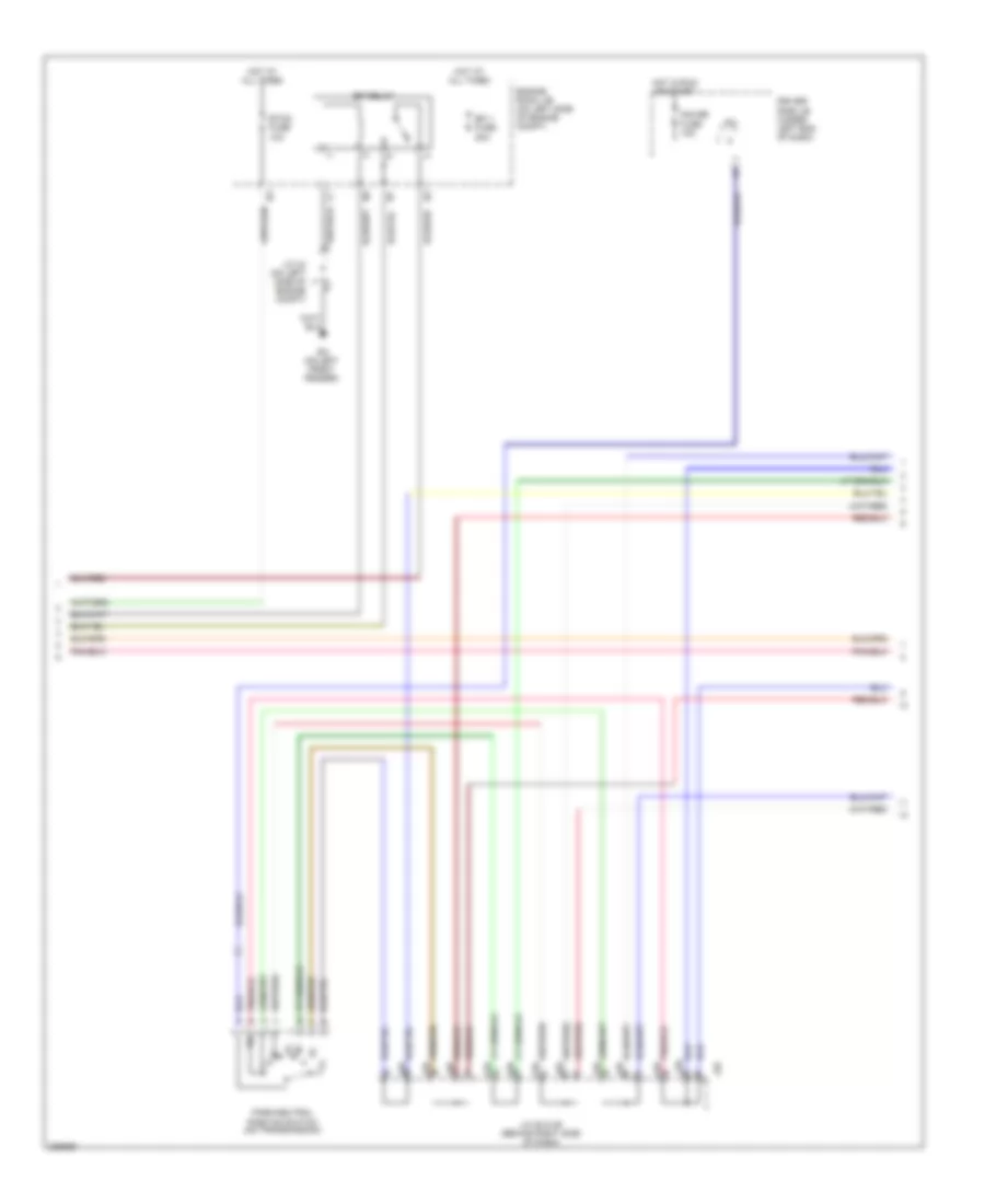
4.0L, A/T Wiring Diagram (3 of 3) for Toyota Tundra Limited 2006
List of elements for 4.0L, A/T Wiring Diagram (3 of 3) for Toyota Tundra Limited 2006:
- (on right rear of engine) eu
- 4wd
- 4wd circuit
- A/t oil temp ind
- Anti-lock brakes system
- C11
- C12
- Canh
- Canl
- Combination meter
- Data link connector 3 (below left side of dash)
- Driver side j/b (behind lower left side of dash)
- Engine control module (ecm) (behind right side of dash)
- F10
- F11
- Hot in run or start
- Ign fuse 5a
- Ih (behind right kick panel)
- Integration control & panel
- J/c 66 (behind right kick panel)
- J/c 71 & 72 (behind upper left side of dash)
- J66 j/c 66 & 67 (behind right kick panel) j67
- J67 j/c 66 & 67 (behind right kick panel) j66
- J71
- J72
- Llp
- Lms
- O/d off ind
- Odlp
- Oilw
- Pnk
- Red
- Spd
- Speed control
- Sta
- Starting/ charging system
- Stsw
4.7L
4.7L, 4WD Wiring Diagram, Access/Standard Cab for Toyota Tundra Limited 2006
List of elements for 4.7L, 4WD Wiring Diagram, Access/Standard Cab for Toyota Tundra Limited 2006:
- (behind upper right side of dash)
- (pins 3-16 not used)
- (w/ vsc)
- (w/o vsc)
- 2-4
- 4hi ind
- 4lo ind
- 4wd
- 4wd control ecu (behind lower right side of dash)
- 4wd fuse 20a
- Abs actuator w/ ecu (in right rear corner of engine compt)
- Acc fuse 15a
- Add
- Add actuator (on left front of engine)
- Anti-lock brakes system
- C11
- C12
- Combination meter
- Detection
- Detection switch (transfer 4wd position) (4.7l: at left side of transmission)
- Detection switch (transfer l4 position) (4.7l: at rear of transmission)
- Diode (a/t) (behind upper left side of dash)
- Dl1
- Dl2
- Dm1
- Dm2
- Driver side j/b (behind lower left side of dash)
- Engine control module (behind right side of dash)
- Exi
- Exi4
- F10
- F20
- F21
- G j28
- G j29
- G11
- Gauge fuse 10a
- Gnd
- H-l
- Hot in on or acc
- Hot in on or start
- I24
- Ign fuse 5a
- Ind1
- Ind3
- Integration control & panel
- J/c 10 (behind upper left side of dash)
- J/c 12
- J/c 13 (behind right kick panel)
- J/c 28 & 29 (behind upper right side of dash)
- J/c 64
- J/c 66 & 67 (behind right kick panel)
- J/c 8 (behind upper left side of dash)
- J/c 9 (behind upper left side of dash)
- J28
- J29
- J66
- J67
- Park/neutral position switch (on transmission)
- Pnk
- Red
- S29
- Skid control ecu w/ actuator (at left rear of engine compt)
- Spd
- Speed control
- Switch
- Tl1
- Tl2
- Tm1
- Tm2
- Tm3
- Transfer shift actuator (4.7l: on transfer case)
4.7L, 4WD Wiring Diagram, Double Cab for Toyota Tundra Limited 2006
List of elements for 4.7L, 4WD Wiring Diagram, Double Cab for Toyota Tundra Limited 2006:
- (behind right side of dash)
- (behind right side of dash) j/c 55 & 56
- (pins 3-16 not used)
- (w/ vsc)
- (w/o vsc)
- 2-4
- 4hi ind
- 4lo ind
- 4wd
- 4wd control ecu (behind right kick panel)
- 4wd fuse 20a
- Abs actuator w/ ecu (in right rear corner of engine compt)
- Add
- Add actuator (on left front of engine)
- Anti-lock brakes system
- B10
- C11
- C12
- Combination meter
- D10
- Detection
- Detection switch (transfer 4wd position) (at left side of transmission)
- Detection switch (transfer l4 position) (at rear of transmission)
- Dl1
- Dl2
- Dm1
- Dm2
- Driver side j/b (under left end of dash)
- Engine control module (behind right side of dash)
- Exi
- Exi4
- F20
- F21
- G j28
- G j29
- Gauge fuse 15a
- Gnd
- H-l
- H11
- Hot in on or start
- I24
- I25
- Ign 1 fuse 10a
- Ind1
- Ind3
- Integration control & panel
- Ipo
- J/c 28 & 29 (behind right side of dash)
- J/c 49 & 50 (behind center of dash)
- J/c 55 & 56 (behind right side of dash)
- J/c 55 & 56 (behind right side of j55 dash)
- J/c 58 (behind right side of dash)
- J/c 64
- J28
- J29
- J49
- J50
- J55
- J56
- Park/neutral position switch (on transmission)
- Pnk
- Red
- S29
- Skid control ecu w/ actuator (at left rear of engine compt)
- Spd
- Speed control
- Sub j/b 4 (behind center of dash)
- Switch
- Tl1
- Tl2
- Tl3
- Tm1
- Tm2
- Transfer shift actuator (on transfer case)
4.7L, A/T Wiring Diagram, Access/Standard Cab (1 of 3) for Toyota Tundra Limited 2006
List of elements for 4.7L, A/T Wiring Diagram, Access/Standard Cab (1 of 3) for Toyota Tundra Limited 2006:
- (behind left side of dash) accelerator pedal position sensor
- (inside transmission) electronically controlled transmission solenoid
- (on rear of engine) ec
- (top left side of engine) ew
- +b2
- +bm
- Batt
- Cruise control system
- E01
- E02
- E03
- E04
- E05
- Engine control module (ecm) (behind right side of dash)
- Engine controls system
- Engine coolant temperature sensor (on right front of engine)
- Epa
- Epa2
- Ge01
- I3 (dash harn, behind right side of dash)
- I4 (dash harn, behind upper right side of dash)
- Igsw
- J/c 3 (behind left kick panel)
- Me01
- Mrel
- No 1
- No 2
- Nsw
- Nt+
- Nt-
- O/d direct clutch speed sensor (on left side of transmission)
- O/d main switch
- Odms
- Red
- Sl1
- Sl1+
- Sl1-
- Sl2
- Sl2+
- Sl2-
- Slt
- Slt+
- Slt-
- Slu
- Slu+
- Slu-
- Sp2+
- Sp2-
- Starting/ charging system
- Stp
- Th02
- Tho1
- Throttle control motor & throttle position sensor (on throttle body assembly)
- Thw
- Vcp2
- Vcpa
- Vehicle speed sensor (electronically controlled transmission) (on transmission)
- Vpa
- Vpa2
- Vta1
- Vta2
4.7L, A/T Wiring Diagram, Access/Standard Cab (2 of 3) for Toyota Tundra Limited 2006
List of elements for 4.7L, A/T Wiring Diagram, Access/Standard Cab (2 of 3) for Toyota Tundra Limited 2006:
- (behind upper left side of dash) diode (a/t)
- (on left side of engine compt) j/c 1
- A j28
- Acc fuse 15a
- B j28
- C j28
- D j28
- Driver side j/b (behind lower left side of dash)
- Ea (on left front fender)
- Efi 1 fuse 20a
- Efi relay
- Engine room r/b (on left side of engine compt)
- Etcs fuse 10a
- F j28
- G j28
- G11
- Gauge fuse 10a
- Hot at all times
- Hot in run or acc
- Hot in run or start
- J/c 18 (on left side of engine compt)
- J/c 26 & 27 (behind left j27 kick panel)
- J/c 28 & 29 (behind upper right side of dash)
- J/c 8 (behind upper left side of dash)
- J/c 9 (behind upper left side of dash)
- J26
- J29
- Park/neutral position switch (on transmission)
4.7L, A/T Wiring Diagram, Access/Standard Cab (3 of 3) for Toyota Tundra Limited 2006
List of elements for 4.7L, A/T Wiring Diagram, Access/Standard Cab (3 of 3) for Toyota Tundra Limited 2006:
- (on rear of engine) ec
- 4wd
- 4wd circuit
- A/t oil temp ind
- Anti-lock brakes system
- C11
- C12
- Canh
- Canl
- Combination meter
- Data link connector 3 (below left side of dash)
- Driver side j/b (behind lower left side of dash)
- Engine control module (ecm) (behind right side of dash)
- F10
- F11
- Hot in run or start
- Ign fuse 5a
- Ih (behind right kick panel)
- Integration control & panel
- J/c 66 (behind right kick panel)
- J/c 71 & 72 (behind upper left side of dash)
- J66 j/c 66 & 67 (behind right kick panel) j67
- J67 j/c 66 & 67 (behind right kick panel) j66
- J71
- J72
- Llp
- Lms
- O/d off ind
- Odlp
- Oilw
- Pnk
- Red
- Spd
- Speed control
- Sta
- Starting/ charging system
- Stsw
4.7L, A/T Wiring Diagram, Double Cab (1 of 3) for Toyota Tundra Limited 2006
List of elements for 4.7L, A/T Wiring Diagram, Double Cab (1 of 3) for Toyota Tundra Limited 2006:
- (behind left side of dash) accelerator pedal position sensor
- (behind right side of dash)
- (inside transmission) electronically controlled transmission solenoid
- (left side of engine) ey
- (on left side of firewall) ec
- +b2
- +bm
- Batt
- Cruise control system
- E01
- E02
- E03
- E04
- E05
- Engine control module (ecm) (behind right side of dash)
- Engine controls system
- Engine coolant temperature sensor (on right front of engine)
- Epa
- Epa2
- Ge01
- I1 (dash harn, behind upper right end of dash)
- Igsw
- J/c 56 (behind right side of dash)
- J/c 58 (behind right side of dash)
- J/c 75
- Me01
- Mrel
- No 1
- No 2
- Nsw
- Nt+
- Nt-
- O/d direct clutch speed sensor (on left side of transmission)
- O/d main switch
- Odms
- Red
- Sl1
- Sl1+
- Sl1-
- Sl2
- Sl2+
- Sl2-
- Slt
- Slt+
- Slt-
- Slu
- Slu+
- Slu-
- Sp2+
- Sp2-
- Starting/ charging system
- Stp
- Th02
- Tho1
- Throttle control motor & throttle position sensor (on throttle body assembly)
- Thw
- Vcp2
- Vcpa
- Vehicle speed sensor (electronically controlled transmission) (on transmission)
- Vpa
- Vpa2
- Vta1
- Vta2
4.7L, A/T Wiring Diagram, Double Cab (2 of 3) for Toyota Tundra Limited 2006
List of elements for 4.7L, A/T Wiring Diagram, Double Cab (2 of 3) for Toyota Tundra Limited 2006:
- A j28
- B j28
- C j28
- D j28
- Driver side j/b (under left end of dash)
- Ea (on left front fender)
- Efi 1 fuse 20a
- Efi relay
- Engine room j/b (on left side of engine compt)
- Etcs fuse 10a
- F j28
- G j28
- Gauge fuse 15a
- Hot at all times
- Hot in run or start
- Ipo
- J/c 28 & 29 (behind right side of dash)
- J/c 34 (on left side of engine compt)
- J29
- Park/neutral position switch (on transmission)
4.7L, A/T Wiring Diagram, Double Cab (3 of 3) for Toyota Tundra Limited 2006
List of elements for 4.7L, A/T Wiring Diagram, Double Cab (3 of 3) for Toyota Tundra Limited 2006:
- (on left side of firewall) ec
- 4wd
- 4wd circuit
- A/t oil temp ind
- Anti-lock brakes system
- C11
- C12
- Canh
- Canl
- Combination meter
- Data link connector 3 (below left side of dash)
- Driver side j/b (under left end of dash)
- E17
- Engine control module (ecm) (behind right side of dash)
- H11
- Hot in run or start
- Ign 1 fuse 10a
- Integration control & panel
- J/c (behind left side of dash)
- J/c 49 (behind center of dash)
- J/c 75 (behind right side of dash)
- J/c 76 & 77 (behind right side of dash)
- J76
- J77
- Llp
- Lms
- O/d off ind
- Odlp
- Oilw
- Pnk
- Spd
- Speed control
- Sta
- Starting/ charging system
- Stsw
- Sub j/b 3 (behind center of dash)