TRANSMISSION
4.0L
4.0L, 4WD Wiring Diagram for Toyota Tundra SR5 2010

List of elements for 4.0L, 4WD Wiring Diagram for Toyota Tundra SR5 2010:
- (4.7l) d7 d3 (5.7l) (rear of engine compt)
- (column shift: left side of dash) (floor shift: left kick panel) j1
- 2-4
- 4hi ind
- 4lo ind
- 4wd
- 4wd control ecu (right side of dash)
- 4wd control switch
- 4wd fuse 20a
- A17
- A24
- A25
- A26
- A4 (right side of engine compt)
- A40
- A41
- A45
- Add
- Add actuator (except 4.0l: front of engine)
- Buzzer
- Canh
- Canl
- Cdl
- Combination meter
- D67
- D68
- D70
- D73
- Dl1
- Dl2
- Dm1
- Dm2
- Driver side j/b (left side of dash)
- Engine control module (right rear of engine compt)
- Engine room r/b (left side of engine compt)
- Ex12
- Gnd
- Gnd1
- Hl1
- Hl2
- Hl3
- Hm1
- Hm2
- Hot at all times
- Hot in on or start
- Ig+
- Ill+
- Ill-
- Interior lights system
- J1 (column shift: left side of dash) (floor shift: left kick panel)
- Junction connector a36 (right side of dash)
- Junction connector a40 & a41 (right side of dash)
- Junction connector a45 & d73 (right rear of engine compt)
- Junction connector d71 (right rear of engine compt)
- Junction connector j113 (column shift: right side of dash) (floor shift: center of dash)
- Junction connector j118 (left side of dash)
- Junction connector j78 (left side of dash)
- Met fuse 7.5a
- Met-b fuse 5a
- Pnk
- Power circuit
- Red
- Skid control ecu w/ actuator (left side of engine compt)
- Tfn
- Tgnd
- Tl1
- Tl3
- Tm1
- Tm2
- Transfer shift actuator (except 4.0l: transfer case assembly)
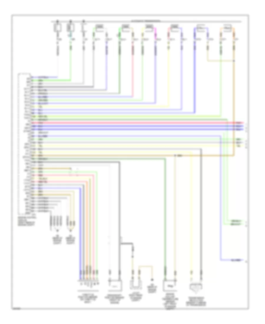
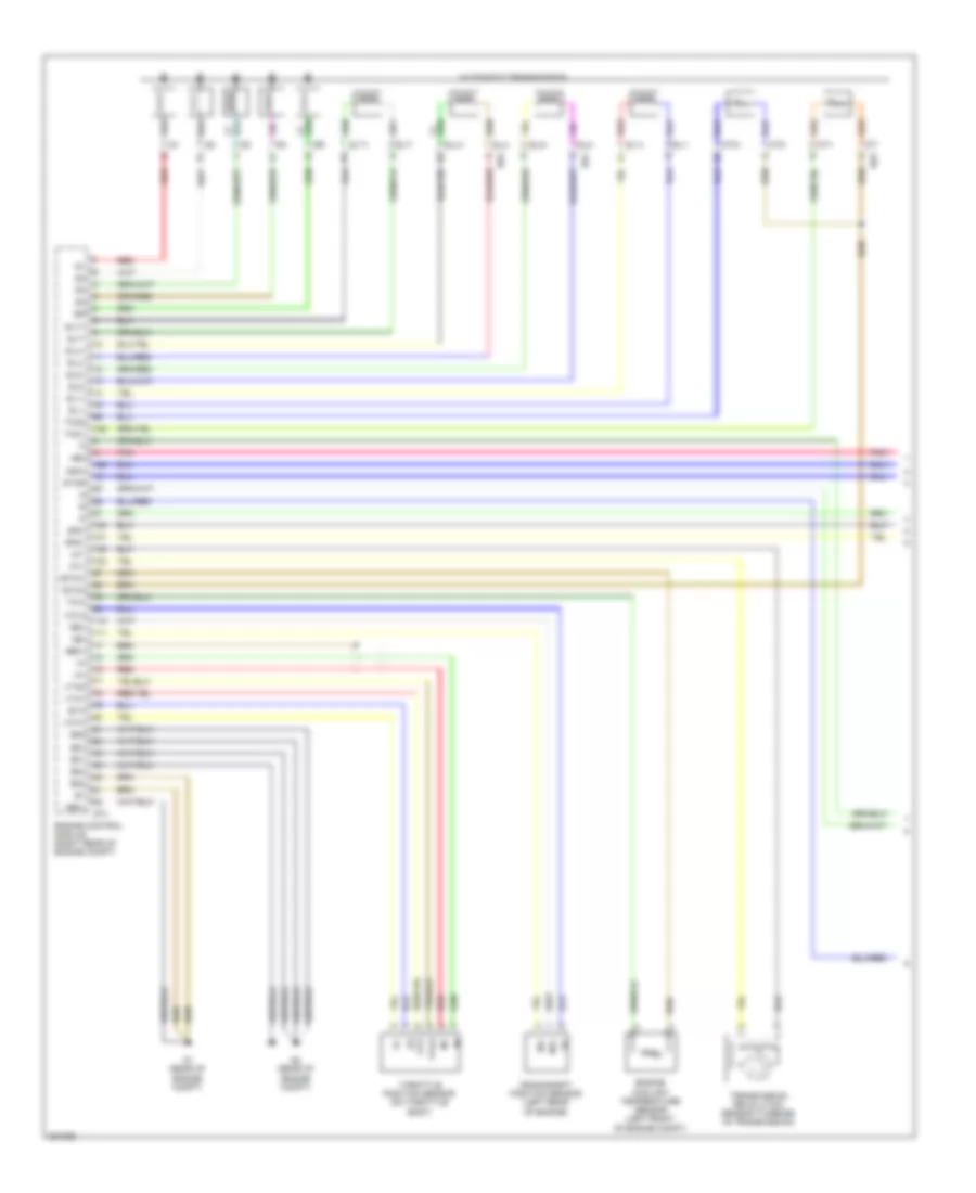
4.0L, A/T Wiring Diagram (1 of 3) for Toyota Tundra SR5 2010
List of elements for 4.0L, A/T Wiring Diagram (1 of 3) for Toyota Tundra SR5 2010:
- +bm
- Automatic transmission
- Crankshaft position sensor (front of engine)
- D74
- D8 (rear of engine compt)
- D9 (rear of engine compt)
- E01
- E02
- E03
- E04
- E05
- Engine control module (right rear of engine compt)
- Engine coolant temperature sensor (left front of engine compt)
- Eta
- Ethw
- Ge01
- J/c d71 (right rear of engine compt)
- Me01
- Nca
- Ne+
- Ne-
- Nsw
- Nt+
- Nt-
- Pnk
- Red
- Red sl1+
- Sl1+
- Sl1-
- Sl2+
- Sl2-
- Slt+
- Slt-
- Slu+
- Slu-
- Sp2+
- Sp2-
- Star
- Tho1
- Tho2
- Throttle position sensor (on throttle body)
- Thw
- Transmission revolution sensor (turbine) (in transmission)
- Vcta
- Vta
- Vta1
- Vta2
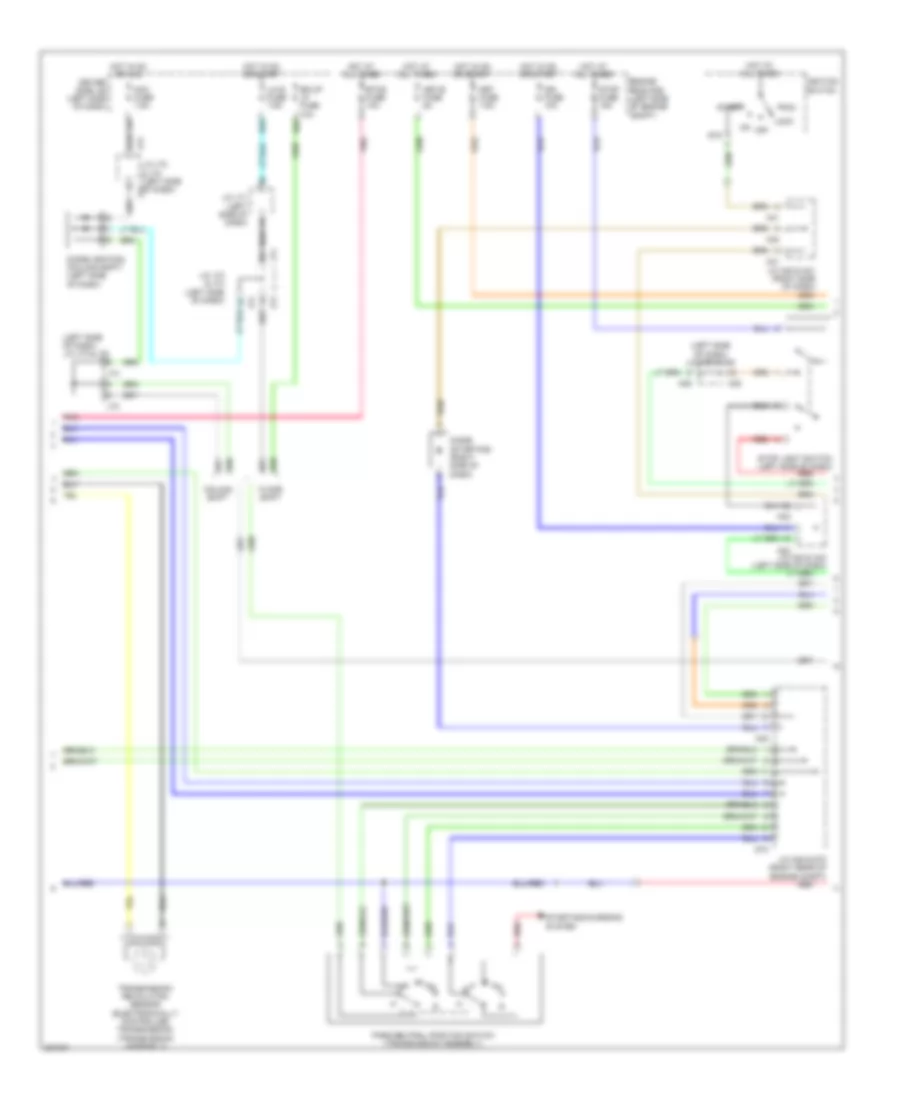
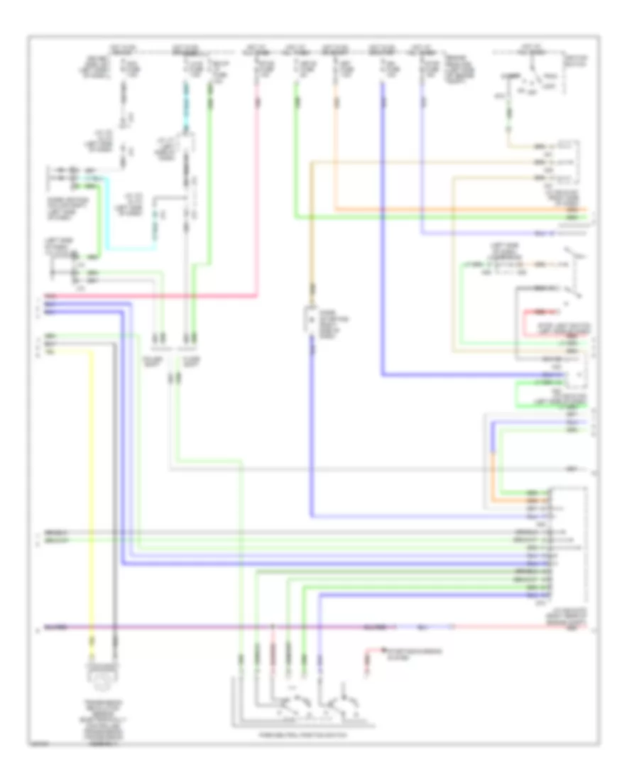
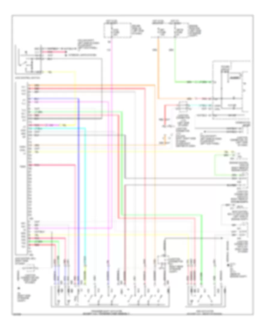
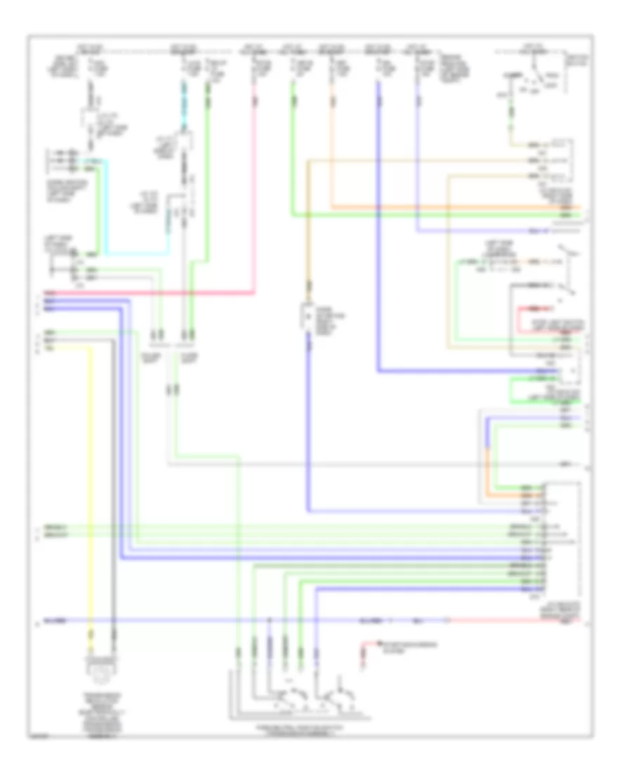
4.0L, A/T Wiring Diagram (2 of 3) for Toyota Tundra SR5 2010
List of elements for 4.0L, A/T Wiring Diagram (2 of 3) for Toyota Tundra SR5 2010:
- (left side of dash) j/c a38 & a39
- (left side of dash) j/c j73 & j74
- A38
- A39
- A40
- A41
- A42
- A43
- A45
- Acc
- Acc fuse 7.5a
- Bk/up lp fuse 10a
- Column shift
- D55
- D65
- D73
- Diode (ignition) (column shift) (left side of dash)
- Diode (starting) (right side of dash)
- Driver side j/b (left side of dash)
- Engine room r/b (left side of engine compt)
- Etcs fuse 10a
- Floor shift
- Hot at all times
- Hot in on or acc
- Hot in on or start
- Ign fuse 10a
- Ignition switch
- J/c a42 & a43 (left side of dash)
- J/c a45 & d73 (right rear of engine compt)
- J/c j71 (left side of dash)
- J/c j73 & j74 (left side of dash)
- J73
- J74
- Lh-ig fuse 7.5a
- Lock
- Met fuse 7.5a
- Met-b fuse 5a
- Off
- Park/neutral position switch (transmission assembly)
- Pnk
- Red
- St2
- Start
- Starting/charging system
- Stop fuse 15a
- Stop light switch (left side of dash)
- Transmission revolution sensor (electronically controlled transmission) (transmission assembly)
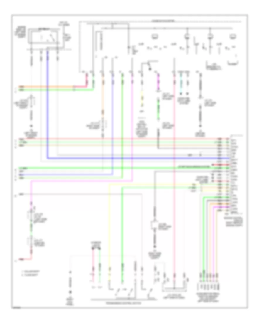
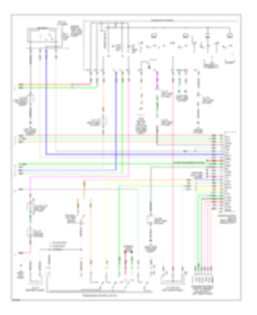
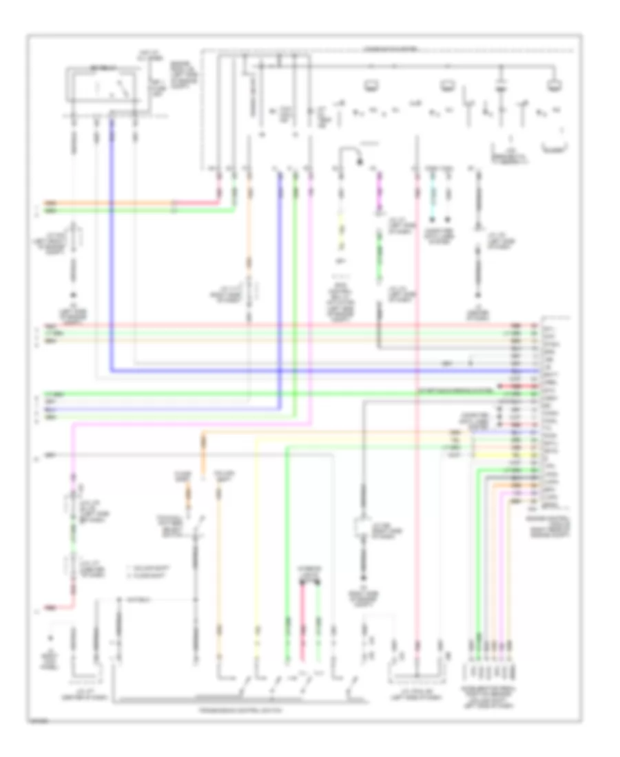
4.0L, A/T Wiring Diagram (3 of 3) for Toyota Tundra SR5 2010
List of elements for 4.0L, A/T Wiring Diagram (3 of 3) for Toyota Tundra SR5 2010:
- +b2
- A/t oil temp ind
- A2 (left front of engine compt)
- A24
- A4 (right side of engine compt)
- Accelerator pedal position sensor (column shift: left side of dash)
- Batt
- Buzzer
- Canh
- Canl
- Column shift
- Combination meter
- Computer data lines system
- Dim
- Efi 1 fuse 25a
- Efi relay
- Engine control module (right rear of engine compt)
- Engine room j/b (left side of engine compt)
- Epa
- Epa2
- Floor shift
- Hot at all times
- Ig+
- Igsw
- Ill+
- Ill-
- Interior lights system
- J/c a36 (right side of dash)
- J/c a44 (left front of engine compt)
- J/c j117 (right side of dash)
- J/c j71 (left side of dash)
- J/c j74 (left side of dash)
- J/c j75 & j76 (left side j75 of dash)
- J/c j77 (center of dash)
- J/c j78 (left side of dash)
- J/c j79 & j80 (left side of dash)
- J2 (center of dash)
- J24
- J25
- J3 (right kick panel)
- J76
- J79
- J80
- Lcd (sequential shift)
- Mrel
- Pnk
- Power circuit
- Red
- Sftd
- Sftu
- Skid control ecu w/ actuator (left side of engine compt)
- Sp1
- Spd
- St1-
- Sta
- Starting/charging system
- Stp
- Stsw
- Transmission control switch
- Vcp2
- Vcpa
- Vpa
- Vpa2
4.6L
4.6L, 4WD Wiring Diagram for Toyota Tundra SR5 2010
List of elements for 4.6L, 4WD Wiring Diagram for Toyota Tundra SR5 2010:
- (4.7l) d7 d3 (5.7l) (rear of engine compt)
- (column shift: left side of dash) (floor shift: left kick panel) j1
- 2-4
- 4hi ind
- 4lo ind
- 4wd
- 4wd control ecu (right side of dash)
- 4wd control switch
- 4wd fuse 20a
- A17
- A24
- A25
- A26
- A4 (right side of engine compt)
- A40
- A41
- A45
- Add
- Add actuator (except 4.0l: front of engine)
- Buzzer
- Canh
- Canl
- Cdl
- Combination meter
- D67
- D68
- D70
- D73
- Dl1
- Dl2
- Dm1
- Dm2
- Driver side j/b (left side of dash)
- Engine control module (right rear of engine compt)
- Engine room r/b (left side of engine compt)
- Ex12
- Gnd
- Gnd1
- Hl1
- Hl2
- Hl3
- Hm1
- Hm2
- Hot at all times
- Hot in on or start
- Ig+
- Ill+
- Ill-
- Interior lights system
- J1 (column shift: left side of dash) (floor shift: left kick panel)
- Junction connector a36 (right side of dash)
- Junction connector a40 & a41 (right side of dash)
- Junction connector a45 & d73 (right rear of engine compt)
- Junction connector d71 (right rear of engine compt)
- Junction connector j113 (column shift: right side of dash) (floor shift: center of dash)
- Junction connector j118 (left side of dash)
- Junction connector j78 (left side of dash)
- Met fuse 7.5a
- Met-b fuse 5a
- Pnk
- Power circuit
- Red
- Skid control ecu w/ actuator (left side of engine compt)
- Tfn
- Tgnd
- Tl1
- Tl3
- Tm1
- Tm2
- Transfer shift actuator (except 4.0l: transfer case assembly)
4.6L, A/T Wiring Diagram (1 of 3) for Toyota Tundra SR5 2010
List of elements for 4.6L, A/T Wiring Diagram (1 of 3) for Toyota Tundra SR5 2010:
- +bm
- Automatic transmission
- Crankshaft position sensor (left front of engine)
- D1 (rear of engine compt)
- D2 (rear of engine compt)
- D74
- E01
- E02
- E03
- E04
- E05
- Engine control module (right rear of engine compt)
- Engine coolant temperature sensor (left front of engine compt)
- Eta
- Etha
- Ge01
- Me01
- Ne+
- Ne-
- Nsw
- Nt+
- Nt-
- Pnk
- Red
- Red sl1+
- Sl1+
- Sl1-
- Sl2+
- Sl2-
- Slt+
- Slt-
- Slu+
- Slu-
- Sp2+
- Sp2-
- Star
- Tho1
- Tho2
- Throttle position sensor (on throttle body)
- Thw
- Transmission revolution sensor (turbine) (in transmission)
- Vcta
- Vcv2
- Vta
- Vta1
- Vta2
4.6L, A/T Wiring Diagram (2 of 3) for Toyota Tundra SR5 2010
List of elements for 4.6L, A/T Wiring Diagram (2 of 3) for Toyota Tundra SR5 2010:
- (left side of dash) j/c a38 & a39
- (left side of dash) j/c j73 & j74
- A38
- A39
- A40
- A41
- A42
- A43
- A45
- Acc
- Acc fuse 7.5a
- Bk/up lp fuse 10a
- Column shift
- D55
- D65
- D73
- Diode (ignition) (column shift) (left side of dash)
- Diode (starting) (right side of dash)
- Driver side j/b (left side of dash)
- Engine room r/b (left side of engine compt)
- Etcs fuse 10a
- Floor shift
- Hot at all times
- Hot in on or acc
- Hot in on or start
- Ign fuse 10a
- Ignition switch
- J/c a42 & a43 (left side of dash)
- J/c a45 & d73 (right rear of engine compt)
- J/c j71 (left side of dash)
- J/c j73 & j74 (left side of dash)
- J73
- J74
- Lh-ig fuse 7.5a
- Lock
- Met fuse 7.5a
- Met-b fuse 5a
- Off
- Park/neutral position switch
- Pnk
- Red
- St2
- Start
- Starting/charging system
- Stop fuse 15a
- Stop light switch (left side of dash)
- Transmission revolution sensor (electronically controlled transmission) (transmission assembly)
4.6L, A/T Wiring Diagram (3 of 3) for Toyota Tundra SR5 2010
List of elements for 4.6L, A/T Wiring Diagram (3 of 3) for Toyota Tundra SR5 2010:
- +b2
- A/t oil temp ind
- A2 (left front of engine compt)
- A24
- A4 (right side of engine compt)
- Accelerator pedal position sensor (column shift: left side of dash)
- Batt
- Buzzer
- Canh
- Canl
- Column shift
- Combination meter
- Computer data lines system
- Dim
- Efi 1 fuse 25a
- Efi relay
- Engine control module (right rear of engine compt)
- Engine room j/b (left side of engine compt)
- Epa
- Epa2
- Floor shift
- Hot at all times
- Ig+
- Igsw
- Ill+
- Ill-
- Interior lights system
- J/c a36 (right side of dash)
- J/c a44 (left front of engine compt)
- J/c j117 (right side of dash)
- J/c j71 (left side of dash)
- J/c j74 (left side of dash)
- J/c j75 & j76 (left side of dash) j75
- J/c j77 (center of dash)
- J/c j78 (left side of dash)
- J/c j79 & j80 (left side of dash)
- J2 (center of dash)
- J24
- J25
- J3 (right kick panel)
- J76
- J79
- J80
- Lcd (sequential shift)
- Mrel
- Pnk
- Power circuit
- Red
- Sftd
- Sftu
- Skid control ecu w/ actuator (left side of engine compt)
- Sp1
- Spd
- St1-
- Sta
- Starting/charging system
- Stp
- Stsw
- Tow
- Tow haul ind
- Tow/haul pattern select switch
- Transmission control switch
- Vcp2
- Vcpa
- Vpa
- Vpa2
5.7L
5.7L, 4WD Wiring Diagram for Toyota Tundra SR5 2010
List of elements for 5.7L, 4WD Wiring Diagram for Toyota Tundra SR5 2010:
- (4.7l) d7 d3 (5.7l) (rear of engine compt)
- (column shift: left side of dash) (floor shift: left kick panel) j1
- 2-4
- 4hi ind
- 4lo ind
- 4wd
- 4wd control ecu (right side of dash)
- 4wd control switch
- 4wd fuse 20a
- A17
- A24
- A25
- A26
- A4 (right side of engine compt)
- A40
- A41
- A45
- Add
- Add actuator (except 4.0l: front of engine)
- Buzzer
- Canh
- Canl
- Cdl
- Combination meter
- D67
- D68
- D70
- D73
- Dl1
- Dl2
- Dm1
- Dm2
- Driver side j/b (left side of dash)
- Engine control module (right rear of engine compt)
- Engine room r/b (left side of engine compt)
- Ex12
- Gnd
- Gnd1
- Hl1
- Hl2
- Hl3
- Hm1
- Hm2
- Hot at all times
- Hot in on or start
- Ig+
- Ill+
- Ill-
- Interior lights system
- J1 (column shift: left side of dash) (floor shift: left kick panel)
- Junction connector a36 (right side of dash)
- Junction connector a40 & a41 (right side of dash)
- Junction connector a45 & d73 (right rear of engine compt)
- Junction connector d71 (right rear of engine compt)
- Junction connector j113 (column shift: right side of dash) (floor shift: center of dash)
- Junction connector j118 (left side of dash)
- Junction connector j78 (left side of dash)
- Met fuse 7.5a
- Met-b fuse 5a
- Pnk
- Power circuit
- Red
- Skid control ecu w/ actuator (left side of engine compt)
- Tfn
- Tgnd
- Tl1
- Tl3
- Tm1
- Tm2
- Transfer shift actuator (except 4.0l: transfer case assembly)
5.7L, A/T Wiring Diagram (1 of 3) for Toyota Tundra SR5 2010
List of elements for 5.7L, A/T Wiring Diagram (1 of 3) for Toyota Tundra SR5 2010:
- +bm
- Automatic transmission
- Crankshaft position sensor (left rear of engine)
- D1 (rear of engine compt)
- D2 (rear of engine compt)
- D63
- D64
- D74
- E01
- E02
- E03
- E04
- E05
- Engine control module (right rear of engine compt)
- Engine coolant temperature sensor (left front of engine compt)
- Eta
- Etha
- Ethw
- Ge01
- Me01
- Ne+
- Ne-
- Nsw
- Nt+
- Nt-
- Pnk
- Red
- Red sl1+
- Sl1+
- Sl1-
- Sl2+
- Sl2-
- Slt+
- Slt-
- Slu+
- Slu-
- Sp2+
- Sp2-
- Star
- Tho1
- Tho2
- Throttle position sensor (on throttle body)
- Thw
- Transmission revolution sensor (turbine) (in transmission)
- Vcta
- Vcv2
- Vta
- Vta1
- Vta2
5.7L, A/T Wiring Diagram (2 of 3) for Toyota Tundra SR5 2010
List of elements for 5.7L, A/T Wiring Diagram (2 of 3) for Toyota Tundra SR5 2010:
- (left side of dash) j/c a38 & a39
- (left side of dash) j/c j73 & j74
- A38
- A39
- A40
- A41
- A42
- A43
- A45
- Acc
- Acc fuse 7.5a
- Bk/up lp fuse 10a
- Column shift
- D55
- D65
- D73
- Diode (ignition) (column shift) (left side of dash)
- Diode (starting) (right side of dash)
- Driver side j/b (left side of dash)
- Engine room r/b (left side of engine compt)
- Etcs fuse 10a
- Floor shift
- Hot at all times
- Hot in on or acc
- Hot in on or start
- Ign fuse 10a
- Ignition switch
- J/c a42 & a43 (left side of dash)
- J/c a45 & d73 (right rear of engine compt)
- J/c j71 (left side of dash)
- J/c j73 & j74 (left side of dash)
- J73
- J74
- Lh-ig fuse 7.5a
- Lock
- Met fuse 7.5a
- Met-b fuse 5a
- Off
- Park/neutral position switch (transmission assembly)
- Pnk
- Red
- St2
- Start
- Starting/charging system
- Stop fuse 15a
- Stop light switch (left side of dash)
- Transmission revolution sensor (electronically controlled transmission) (transmission assembly)
5.7L, A/T Wiring Diagram (3 of 3) for Toyota Tundra SR5 2010
List of elements for 5.7L, A/T Wiring Diagram (3 of 3) for Toyota Tundra SR5 2010:
- +b2
- A/t oil temp ind
- A2 (left side of engine compt)
- A24
- A4 (right side of engine compt)
- Accelerator pedal position sensor (column shift: left side of dash)
- Batt
- Buzzer
- Canh
- Canl
- Column shift
- Combination meter
- Computer data lines system
- Dim
- Efi 1 fuse 25a
- Efi relay
- Engine control module (right rear of engine compt)
- Engine room j/b (left side of engine compt)
- Epa
- Epa2
- Floor shift
- Hot at all times
- Ig+
- Igsw
- Ill+
- Ill-
- Interior lights system
- J/c a36 (right side of dash)
- J/c a44 (left front of engine compt)
- J/c j117 (right side of dash)
- J/c j71 (left side of dash)
- J/c j74 (left side of dash)
- J/c j75 & j76 (left side j75 of dash)
- J/c j77 (center of dash)
- J/c j78 (left side of dash)
- J/c j79 & j80 (left side of dash)
- J2 (center of dash)
- J24
- J25
- J3 (right kick panel)
- J76
- J79
- J80
- Lcd (sequential shift)
- Mrel
- Pnk
- Power circuit
- Pwr
- Red
- Sftd
- Sftu
- Skid control ecu w/ actuator (left side of engine compt)
- Sp1
- Spd
- St1-
- Sta
- Starting/charging system
- Stp
- Stsw
- Tow haul ind
- Tow/haul pattern select switch
- Transmission control switch
- Vcp2
- Vcpa
- Vpa
- Vpa2
5.7L FLEX FUEL
5.7L Flex Fuel, 4WD Wiring Diagram for Toyota Tundra SR5 2010
List of elements for 5.7L Flex Fuel, 4WD Wiring Diagram for Toyota Tundra SR5 2010:
- (4.7l) d7 d3 (5.7l) (rear of engine compt)
- (column shift: left side of dash) (floor shift: left kick panel) j1
- 2-4
- 4hi ind
- 4lo ind
- 4wd
- 4wd control ecu (right side of dash)
- 4wd control switch
- 4wd fuse 20a
- A17
- A24
- A25
- A26
- A4 (right side of engine compt)
- A40
- A41
- A45
- Add
- Add actuator (except 4.0l: front of engine)
- Buzzer
- Canh
- Canl
- Cdl
- Combination meter
- D67
- D68
- D70
- D73
- Dl1
- Dl2
- Dm1
- Dm2
- Driver side j/b (left side of dash)
- Engine control module (right rear of engine compt)
- Engine room r/b (left side of engine compt)
- Ex12
- Gnd
- Gnd1
- Hl1
- Hl2
- Hl3
- Hm1
- Hm2
- Hot at all times
- Hot in on or start
- Ig+
- Ill+
- Ill-
- Interior lights system
- J1 (column shift: left side of dash) (floor shift: left kick panel)
- Junction connector a36 (right side of dash)
- Junction connector a40 & a41 (right side of dash)
- Junction connector a45 & d73 (right rear of engine compt)
- Junction connector d71 (right rear of engine compt)
- Junction connector j113 (column shift: right side of dash) (floor shift: center of dash)
- Junction connector j118 (left side of dash)
- Junction connector j78 (left side of dash)
- Met fuse 7.5a
- Met-b fuse 5a
- Pnk
- Power circuit
- Red
- Skid control ecu w/ actuator (left side of engine compt)
- Tfn
- Tgnd
- Tl1
- Tl3
- Tm1
- Tm2
- Transfer shift actuator (except 4.0l: transfer case assembly)
5.7L Flex Fuel, A/T Wiring Diagram (1 of 3) for Toyota Tundra SR5 2010
List of elements for 5.7L Flex Fuel, A/T Wiring Diagram (1 of 3) for Toyota Tundra SR5 2010:
- +bm
- Automatic transmission
- Crankshaft position sensor (left rear of engine)
- D1 (rear of engine compt)
- D2 (rear of engine compt)
- D63
- D64
- D74
- E01
- E02
- E03
- E04
- E05
- Engine control module (right rear of engine compt)
- Engine coolant temperature sensor (left front of engine compt)
- Eta
- Etha
- Ethw
- Ge01
- Me01
- Ne+
- Ne-
- Nsw
- Nt+
- Nt-
- Pnk
- Red
- Red sl1+
- Sl1+
- Sl1-
- Sl2+
- Sl2-
- Slt+
- Slt-
- Slu+
- Slu-
- Sp2+
- Sp2-
- Star
- Tho1
- Tho2
- Throttle position sensor (on throttle body)
- Thw
- Transmission revolution sensor (turbine) (in transmission)
- Vcta
- Vcv2
- Vta
- Vta1
- Vta2
5.7L Flex Fuel, A/T Wiring Diagram (2 of 3) for Toyota Tundra SR5 2010
List of elements for 5.7L Flex Fuel, A/T Wiring Diagram (2 of 3) for Toyota Tundra SR5 2010:
- (left side of dash) j/c a38 & a39
- (left side of dash) j/c j73 & j74
- A38
- A39
- A40
- A41
- A42
- A43
- A45
- Acc
- Acc fuse 7.5a
- Bk/up lp fuse 10a
- Column shift
- D55
- D65
- D73
- Diode (ignition) (column shift) (left side of dash)
- Diode (starting) (right side of dash)
- Driver side j/b (left side of dash)
- Engine room r/b (left side of engine compt)
- Etcs fuse 10a
- Floor shift
- Hot at all times
- Hot in on or acc
- Hot in on or start
- Ign fuse 10a
- Ignition switch
- J/c a42 & a43 (left side of dash)
- J/c a45 & d73 (right rear of engine compt)
- J/c j71 (left side of dash)
- J/c j73 & j74 (left side of dash)
- J73
- J74
- Lh-ig fuse 7.5a
- Lock
- Met fuse 7.5a
- Met-b fuse 5a
- Off
- Park/neutral position switch (transmission assembly)
- Pnk
- Red
- St2
- Start
- Starting/charging system
- Stop fuse 15a
- Stop light switch (left side of dash)
- Transmission revolution sensor (electronically controlled transmission) (transmission assembly)
5.7L Flex Fuel, A/T Wiring Diagram (3 of 3) for Toyota Tundra SR5 2010
List of elements for 5.7L Flex Fuel, A/T Wiring Diagram (3 of 3) for Toyota Tundra SR5 2010:
- +b2
- A/t oil temp ind
- A2 (left side of engine compt)
- A24
- A4 (right side of engine compt)
- Accelerator pedal position sensor (column shift: left side of dash)
- Batt
- Buzzer
- Canh
- Canl
- Column shift
- Combination meter
- Computer data lines system
- Dim
- Efi 1 fuse 25a
- Efi relay
- Engine control module (right rear of engine compt)
- Engine room j/b (left side of engine compt)
- Epa
- Epa2
- Floor shift
- Hot at all times
- Ig+
- Igsw
- Ill+
- Ill-
- Interior lights system
- J/c a36 (right side of dash)
- J/c a44 (left front of engine compt)
- J/c j117 (right side of dash)
- J/c j71 (left side of dash)
- J/c j74 (left side of dash)
- J/c j75 & j76 (left side j75 of dash)
- J/c j77 (center of dash)
- J/c j78 (left side of dash)
- J/c j79 & j80 (left side of dash)
- J2 (center of dash)
- J24
- J25
- J3 (right kick panel)
- J76
- J79
- J80
- Lcd (sequential shift)
- Mrel
- Pnk
- Power circuit
- Pwr
- Red
- Sftd
- Sftu
- Skid control ecu w/ actuator (left side of engine compt)
- Sp1
- Spd
- St1-
- Sta
- Starting/charging system
- Stp
- Stsw
- Tow haul ind
- Tow/haul pattern select switch
- Transmission control switch
- Vcp2
- Vcpa
- Vpa
- Vpa2