Audi A6 Avant Quattro 2001 - 2001 ELECTRICAL Fuses & Circuit Breakers - A6, A6 Avant Quattro, A6 Quattro & Allroad
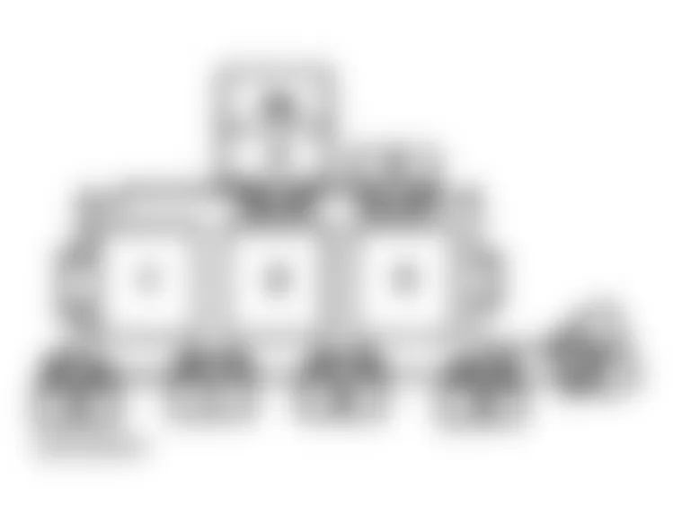
Audi A6 Avant Quattro 2001 - IDENTIFICATION ENGINE CODE
Engines are identified by a 3-letter code stamped on engine. On vehicles equipped with engine code APB or ATQ, engine code is on machined surface on cylinder block, at front right cylinder bank. The engine code is also indicated on the vehicle data sticker. See Fig. 1 or Fig. 2 . On vehicles equipped with engine code ART, letters are located on left side of cylinder block. The engine code is also included on vehicle data label. See Fig. 3.

Fig. 1: Audi A6 Avant Quattro 2001 - Component Locations - Identifying Engine Code Location (2.7L - APB)
Fig. 2: Audi A6 Avant Quattro 2001 - Component Locations - Identifying Engine Code Location (2.8L - ATQ)
Fig. 3: Audi A6 Avant Quattro 2001 - Component Locations - Identifying Engine Code Location (4.2L - ART)
Audi A6 Avant Quattro 2001 - FUSES FUSE COLOR IDENTIFICATION
Audi A6 Avant Quattro 2001 FUSE COLOR/AMP RATING
| Fuse Color | Amp Rating |
| Blue | 15 |
| Brown | 7.5 |
| Green | 30 |
| Light Brown | 5 |
| Red | 10 |
| Transparent (White) | 25 |
| Yellow | 20 |
Audi A6 Avant Quattro 2001 - FUSE PANEL LOCATION
Fuse panel is located behind left side of dashboard. See Fig. 4.
Fig. 4: Audi A6 Avant Quattro 2001 - Component Locations - Locating Fuse Panel
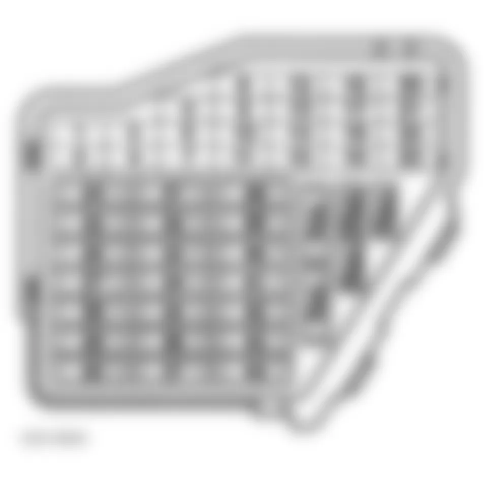
Audi A6 Avant Quattro 2001 - FUSE PANEL IDENTIFICATION
For fuse position within panel, see Fig. 5. For fuse number, amperage rating and circuits protected, see FUSE IDENTIFICATION (FUSE PANEL) table.
Fig. 5: Audi A6 Avant Quattro 2001 - Component Locations - Identifying Fuse Panel Fuses
| NOTE: | Fuses 23 through 44 may be designated in wiring diagrams with a prefix of 2. For example, fuse No. 29 may be labeled as 229. Fuse No. 43 may be labeled as 243. |
Audi A6 Avant Quattro 2001 FUSE IDENTIFICATION (FUSE PANEL)
| Fuse No. | Amp Rating | Circuits Protected |
| 1 | 5 | Washer Nozzle Heaters |
| 2 | 10 | Emergency Flasher Switch & Relay |
| 3 | 5 | Glove Compartment Light |
| 4 | 5 | License Plate Light |
| 5 | 10 | Heated Seat Adjusters, Telephone Transceiver, Navigation W/CD Drive Control Unit, Parking Aid Control Module, Lamp Control Module, A/C Control Head, Air Quality Sensor, Mirror Adjustment, Mirror Fold-Away Function Control Module, Rear Window Shade, Radio, Oil Level Thermal Sensor, Level Control System Control Head (1), Level Control System Control Module (1) |
| 6 | 5 | Central Locking Control Module |
| 7 | 10 | Brake Vacuum Vent Valve, Anti Slip Control Switch, ABS Control Module, Level Control System Control Head, Clutch Vacuum Vent Valve Switch (2), ECM (2) |
| 8 | 5 | Telephone Transceiver, Central Locking Control Module, Operating Electronic (Telephone) Control Module |
| 9 | 10 | Heated Outside Mirrors |
| 10 | 5 | Headlight Beam Adjustment Motors, Beam Adjustment Control Module |
| 11 | N/A | Not Used |
| 12 | 10 | DLC |
| 13 | 10 | Brake Light Switch |
| 14 | 10 | Central Locking Control Module, Door Warning Lights, Passenger Compartment Monitoring Switch, Trunk Lid Release Switch, Memory Program Switch, Memory Control Head (Driver's & Passenger's Seat) |
| 15 | 10 | Instrument Cluster, Solar Cell Separation Relay, Memory Control Module, Mirror Memory Circuit Control Module, Navigation W/CD Drive Control Unit |
| 16 | 5 | Steering Angle Sensor |
| 17 | 10 | Level Control System Control Module, Combustion Air Blower Capacitor, Tire Pressure Monitoring Control Module, Parking Aid Control Module (1) |
| 18 | 10 | High Beam (Right), Headlight High Beam Indicator Light, Instrument Cluster Combination Processor (3) |
| 19 | 10 | High Beam (Left), Fog Light Relay |
| 20 | 15 | Lamp Control Module, Low Beam Headlight (Right) |
| 21 | 15 | Lamp Control Module, Low Beam Headlight (Left) |
| 22 | 5 | Lamp Control Module, Tail Light (Right), Parking Light (Right) |
| 23 | 5 | Lamp Control Module, Tail Light (Left), Parking Light (Left) |
| 24 | 25 | Wiper/Washer Intermittent Relay |
| 25 | 30 | Fresh Air Blower, Solar Cell Separation Relay, A/C Pressured Switch, A/C Control Head, A/C Clutch Relay |
| 26 | 30 | Air Quality Sensor, A/C Control Head, Rear Window Defogger Switch |
| 27 | 15 | Rear Window Wiper Motor, Heated Steering Wheel Control Unit |
| 28 | 20 | Fuel Pump |
| 29 |
| Engine Code APB | 30 | Ignition Coils |
| Engine Code ATQ | 30 | Ignition Coils, Distributor Ignition Capacitor |
| Engine Code ART | 30 | Camshaft Adjustment Valves, Ignition Coils |
| 30 | 20 | Power Sunroof Control Module |
| 31 |
| Manual Transmission | 15 | Back-Up Light Switch, Automatic Day/Night Interior Mirror, DLC, Garage Door Opener Control Module |
| Automatic Transmission | 15 | Automatic Day/Night Interior Mirror, DLC, Multi-Function Transmission Range Switch, Shift Lock Solenoid, Cruise Control Switch, ECM (4), Garage Door Opener Control Module |
| 32 | 20 | Cruise Control Switch, Fuel Injectors |
| 33 | 15 | Cigarette Lighters |
| 34 |
| Engine Code APB | 15 | MAF Sensor, Oxygen Sensor Heaters, Camshaft Adjustment Valves, EVAP Canister Purge Valve, Secondary Air Injection Solenoid Valve, Secondary Air Injection Pump Relay, Leak Detection Pump, Exhaust Temperature Sensors, Wastegate Bypass Regulator Valve, Central Idle Air Control Cut-Off Valve |
| Engine Code ATQ | 15 | MAF Sensor, Oxygen Sensor Heaters, Camshaft Adjustment Valves, EVAP Canister Purge Valve, Secondary Air Injection Solenoid Valve, Secondary Air Injection Pump Relay, Intake Manifold Change-Over Valve, Leak Detection Pump |
| Engine Code ART | 25 | MAF Sensor, Oxygen Sensor Heaters, EVAP Canister Purge Valve, Secondary Air Injection Solenoid Valve, Secondary Air Injection Pump Relay, Electrohydraulic Engine Mount Solenoid Valve (Left & Right), Intake Manifold Change-Over Valve, Intake Manifold Tuning Valve No. 2, Leak Detection Pump |
| 35 | 30 | Trailer Socket |
| 36 | 15 | Fog Light Switch |
| 37 | 20 | Radio, Right Rear Woofer/Amp, Power Antenna |
| 38 | 20 | Central Locking Control Module |
| 39 | 15 | Emergency Flasher Switch |
| 40 | 25 | Dual Horn Relay |
| 41 | 25 | ABS Solenoid Valve |
| 42 | 25 | ABS Solenoid Valve |
| 43 | N/A | Not Used |
| 44 | 30 | Memory Seat Control Module, Driver's Seat Lumbar Support Adjustment Switch, Heated Seat Adjusters |
| (1) | Applies to Allroad models only. | | (2) | Applies to vehicles equipped with engine code ART only. | | (3) | Applies to vehicles equipped with high intensity gas discharge lamps only. | | (4) | Applies to vehicles equipped with engine code ATQ and front wheel drive only. | |
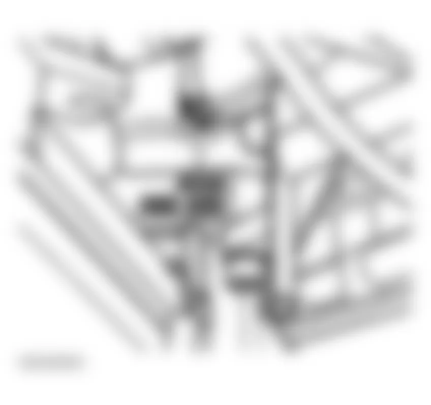
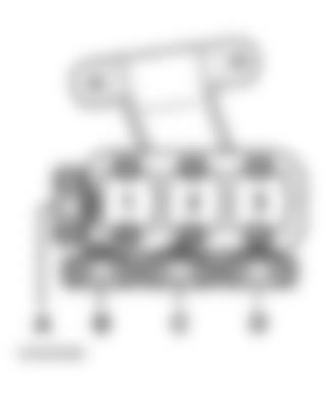
Audi A6 Avant Quattro 2001 - RELAYS THREE FOLD RELAY PANEL (E-BOX)
For fuse and relay positions within panel, see Fig. 6. For relay number, position number and circuits protected, see RELAY IDENTIFICATION (THREE FOLD RELAY PANEL) table. For fuse number, amperage rating, and circuits protected, see FUSE IDENTIFICATION (THREE FOLD RELAY PANEL) table.
| NOTE: | Three fold relay panel is located in electronics box, plenum chamber, in the left rear corner of engine compartment. |
| NOTE: | Manufacturer does not provide fuse number, amperage rating, or circuits protected for three fold relay panel fuses. |
Fig. 6: Audi A6 Avant Quattro 2001 - Component Locations - Identifying Three Fold Relay Components (E-Box Panel)
Audi A6 Avant Quattro 2001 RELAY IDENTIFICATION (THREE FOLD RELAY PANEL, E-BOX)
| Position | Relay No. | Circuit Protected |
| 1 | N/A | Not Used |
| 2 | J299 | Secondary Air Injection Pump Relay |
| 3 (1) | J271 | Motronic ECM Power Supply |
| (1) | Applies to vehicles equipped with engine code ART only. | |
Audi A6 Avant Quattro 2001 FUSE IDENTIFICATION (THREE FOLD RELAY PANEL, E-BOX)
| Position | Fuse No. | Amp Rating | Circuit Protected |
| 4 | N/A | N/A | Not Used |
| 5 | N/A | N/A | Not Used |
| 6 | N/A | N/A | Not Used |
| 7 | S130 | 40 | Secondary Air Pump |
| 8 | N/A | N/A | Not Used |
| 9 | N/A | N/A | Not Used |
Audi A6 Avant Quattro 2001 - THREE FOLD RELAY PANEL (INSTRUMENT PANEL)
For fuse and relay position within panel, see Fig. 7. For relay number, position number and circuits protected, see RELAY IDENTIFICATION (THREE FOLD RELAY PANEL, INSTRUMENT PANEL) table. For fuse number, position number, amperage rating, and circuits protected, see FUSE IDENTIFICATION (THREE FOLD RELAY PANEL, INSTRUMENT PANEL) table.
| NOTE: | Three fold relay panel is located behind instrument panel on central girder. |
Fig. 7: Audi A6 Avant Quattro 2001 - Component Locations - Identifying Three Fold Relay Components (Instrument Panel)
Audi A6 Avant Quattro 2001 RELAY IDENTIFICATION (THREE FOLD RELAY PANEL, INSTRUMENT PANEL)
| Position No. | Relay No. | Circuit Protected |
| 1 | J569 | Brake Booster |
| 2 | N/A | Not Used |
| 3 | N/A | Not Used |
Audi A6 Avant Quattro 2001 FUSE IDENTIFICATION (THREE FOLD RELAY PANEL, INSTRUMENT PANEL)
| Position No. | Fuse No. | Amp Rating | Circuit Protected |
| A | N/A | N/A | Not Used |
| B | N/A | N/A | Not Used |
| C | S279 | 15 | Brake Booster Relay |
| D | N/A | N/A | Not Used |
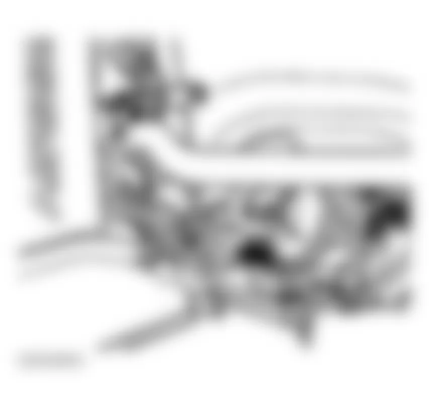
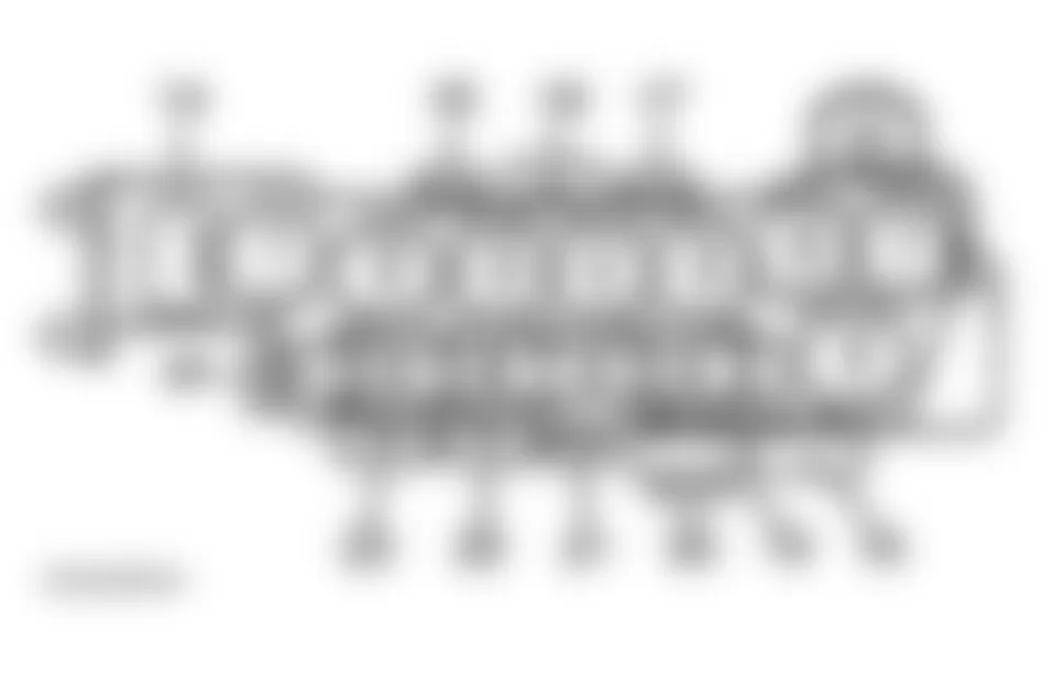
Audi A6 Avant Quattro 2001 - EIGHT FOLD RELAY PANEL
For fuse and relay positions within carrier, see Fig. 8. For relay number, position number and circuits protected, see RELAY IDENTIFICATION (EIGHT FOLD RELAY PANEL) table. For fuse number, position number, amperage rating and circuits protected, see FUSE IDENTIFICATION (EIGHT FOLD RELAY PANEL) table.
| NOTE: | Eight fold relay panel is located behind trim panel, under driver's side of instrument panel. |
Fig. 8: Audi A6 Avant Quattro 2001 - Component Locations - Identifying Eight Fold Relay Panel Components
Audi A6 Avant Quattro 2001 RELAY IDENTIFICATION (EIGHT FOLD RELAY PANEL)
| Position No. | Relay No. | Circuit Protected |
| 1 | N/A | Not Used |
| 2 | J101 | Second Speed Coolant Fan Control |
| 3 | J26 | Coolant Fan Control |
| 4 (1) | J106 | ABS Solenoid Valve |
| 5 | N/A | Not Used |
| 6 (2) | J403 | Compressor Level Control System |
| 7 (1) | J105 | ABS Return Flow Pump |
| 8 | N/A | Not Used |
| (1) | Applies to vehicles equipped with electronic stabilization program only. | | (2) | Applies to Allroad models only. | |
Audi A6 Avant Quattro 2001 FUSE IDENTIFICATION (EIGHT FOLD RELAY PANEL)
| Position No. | Fuse No. | Amp Rating | Circuit Protected |
| 9 | N/A | N/A | Not Used |
| 10 | N/A | N/A | Not Used |
| 11 | N/A | N/A | Not Used |
| 12 | N/A | N/A | Not Used |
| 13 | N/A | N/A | Not Used |
| 14 | S44 | 30 | Power Seat Circuit Breaker No. 1 |
| 15 | S184 | 20 | Luggage Compartment Socket |
| 16 | S37 | 30 | Power Window Circuit Breaker (Front) |
| 17 | S43 | 30 | Power Window Circuit Breaker (Rear) |
| 18 | S123 | 50 | ABS Control Module |
| 19 | N/A | N/A | Not Used |
| 20 | S42 | 60 (1) | Coolant Fan |
| 21 | S142 | 5 | Coolant Fan Control Module |
| 22 | N/A | N/A | Not Used |
| 23 | S110 | 40 | Self-Leveling System |
| 24 | S80 | 30 | Power Seat Circuit Breaker No. 2 |
| (1) | On vehicles equipped with 300W coolant fan, amperage is 40A. | |
Audi A6 Avant Quattro 2001 - THIRTEEN FOLD RELAY PANEL
For fuse and relay position within carrier, see Fig. 9. For relay number, position number and circuits protected, see RELAY IDENTIFICATION (THIRTEEN FOLD RELAY PANEL) table. For fuse number, position number, amperage rating and circuits protected, see FUSE IDENTIFICATION (THIRTEEN FOLD RELAY PANEL) table.
| NOTE: | Thirteen fold relay panel is located behind trim panel under driver's side of instrument panel. |
Fig. 9: Audi A6 Avant Quattro 2001 - Component Locations - Identifying Thirteen Fold Panel Components
Audi A6 Avant Quattro 2001 RELAY IDENTIFICATION (THIRTEEN FOLD RELAY PANEL)
| Position No. | Relay No. | Circuit Protected |
| 1 | N/A | Not Used |
| 2 | N/A | Not Used |
| 3 | J309 | Solar Cell Separation |
| 4 | J207 | Starting Interlock |
| 5 | J44 | A/C Clutch |
| 6 | J5 | Fog Light |
| 7 | J453 | Multi-Function Steering Wheel |
| 8 | J453 | Multi-Function Steering Wheel |
| 9 | J123 | Lamp Control Module |
| 10 | J123 | Lamp Control Module |
| 11 | J351 | Mirror Fold-Away Function Control Module |
| 12 | J351 | Mirror Fold-Away Function Control Module |
| 13 | J236 | Servotronic Control Module |
Audi A6 Avant Quattro 2001 FUSE IDENTIFICATION (THIRTEEN FOLD RELAY PANEL)
| Position No. | Fuse No. | Amp Rating | Circuit Protected |
| 14 (1) | S279 | 20 | Hydraulic Pump Relay |
| 15 | N/A | N/A | Not Used |
| 16 | N/A | N/A | Not Used |
| 17 (2) | S28 | 12 | Fog Light Circuit Breaker |
| 18 | N/A | N/A | Not Used |
| (1) | Applies to Allroad models only. | | (2) | Applies to vehicles produced in Canada only. | |
Audi A6 Avant Quattro 2001 - MICRO CENTRAL ELECTRIC PANEL
For relay position within panel, see Fig. 10. For relay number, position number and circuits protected, see RELAY IDENTIFICATION (MICRO CENTRAL ELECTRIC PANEL) and RELAY IDENTIFICATION (MICRO CENTRAL ELECTRIC PANEL) tables.
| NOTE: | Micro central electric panel is located in driver's side footwell, behind trim panel. |
Fig. 10: Audi A6 Avant Quattro 2001 - Component Locations - Identifying Micro Central Electric Components
Audi A6 Avant Quattro 2001 RELAY IDENTIFICATION (MICRO CENTRAL ELECTRIC PANEL)
| Position No. | Relay No. | Circuit Protected |
| 1 | J4 | Dual Horn |
| 2 | J59 | Load Reduction |
| 3 (1) | J555 | Low Range Hydraulic Pump |
| 4 | J17 | Fuel Pump |
| 5 | J31 | Wiper/Washer Intermittent |
| 6 | J31 | Wiper/Washer Intermittent |
| (1) | Applies to Allroad models only. | |
Audi A6 Avant Quattro 2001 RELAY IDENTIFICATION (MICRO CENTRAL ELECTRIC PANEL)
| Position No. | Fuse No. | Amp Rating | Circuit Protected |
| A | S275 | 20 | Steering Column Adjustment |
| B | S100 | 10 | Rear Shade |
| C | N/A | N/A | Not Used |