
Audi Cabriolet 1998 - 1998 ENGINE PERFORMANCE Self-Diagnostics - Introduction
Audi Cabriolet 1998 - INTRODUCTION
If no faults were found during preliminary inspection, proceed with self-diagnostics. If no trouble codes or only pass codes are present after entering self-diagnostics, proceed to TESTS W/O CODES article for diagnosis by symptom (i.e., ROUGH IDLE, NO START, etc.).
Audi Cabriolet 1998 - SELF-DIAGNOSTIC SYSTEM
NOTE: It is necessary to generate a PCM readiness code if PCM memory is cleared, battery voltage is disconnected or PCM is disconnected. See CLEARING CODES . If PCM was replaced, see PCM REPLACING .
Audi Cabriolet 1998 - DIAGNOSTIC TROUBLE CODES (DTCS)
The Powertrain Control Module (PCM) can identify malfunctions and store them in memory in the form of a Diagnostic Trouble Code (DTC). DTCs are stored until memory is erased. If positive battery cable or PCM connector is disconnected, DTCs are erased.
Audi Cabriolet 1998 - MALFUNCTION INDICATOR LIGHT (MIL)
MIL will illuminate if a failure occurs with Powertrain Control Module (PCM) or Transmission Control Module (TCM). If a failure occurs associated with TCM, see IMPORTED TRANSMISSION SERVICE & REPAIR section.
When ignition is turned on, MIL should come on. When engine is started, MIL should turn off after a couple of seconds. If MIL does not turn off after engine is started, or if MIL comes on while driving, retrieve Diagnostic Trouble Codes (DTCs). See RETRIEVING CODES .
If MIL lights continuously, a malfunction is present that will cause an increase in emissions. If MIL starts to blink, a malfunction is present which may lead to catalytic converter damage. Repair these failures as quickly as possible. For some failures, MIL is only turned on after failure occurs after 2 successive trips with cold engine starts preceding failure.
Some failures will set a DTC which will never cause MIL to light. An example of a failure that could occur and not cause MIL to light would be a FUEL LEVEL TOO LOW signal generated on a A4 1.8L model.
NOTE: If MIL is on continuously and no DTCs are stored, perform MIL check. See MIL CHECK . If MIL never illuminates, see MIL CHECK .
Audi Cabriolet 1998 - HARD FAILURES
Hard failures (also called static malfunctions) cause MIL to come on and a code to set in Powertrain Control Module (PCM) memory. A code that sets as a result of a hard failure will not be erased automatically when the problem is eliminated. These codes must be erased manually.
Audi Cabriolet 1998 - INTERMITTENT FAILURES
When an intermittent failure occurs, MIL comes on and a Diagnostic Trouble Code (DTC) sets. Powertrain Control Module (PCM) stores DTC as sporadic. Intermittent (sporadic) failures will be erased by PCM if failure does not occur again within 40 engine starts on Cabriolet, or after 50 engine starts with engine reaching operating temperature on 1.8L and 2.8L (except Cabriolet). Intermittent failures may be caused by problems with a sensor, connector or wiring. See INTERMITTENTS in TESTS W/O CODES article.
Audi Cabriolet 1998 - RETRIEVING CODES
NOTE: If Malfunction Indicator Light (MIL) is on continuously and no DTCs are stored, perform MIL check. See MIL CHECK . If MIL never illuminates, see MIL CHECK .
Audi Cabriolet 1998 - Visual Inspection
Prior to retrieving Diagnostic Trouble Codes (DTCs), perform a comprehensive visual inspection of ground connections located on intake manifold, ensure battery negative cable is okay, and check ground cable between engine and vehicle body. Repair as necessary. Check vacuum hoses for breakage and blockage. Check electrical wiring and connectors for damage and corrosion. Repair as necessary.
NOTE: Manufacturer does not provide procedure for retrieving DTCs without scan tool. If using Volkswagen Audi Group (VAG) 1551 scan tool for diagnosis, follow manufacturer's instructions for operation. VAG 1551 is recommended for diagnosing DTCs.
Audi Cabriolet 1998 - Retrieving Codes
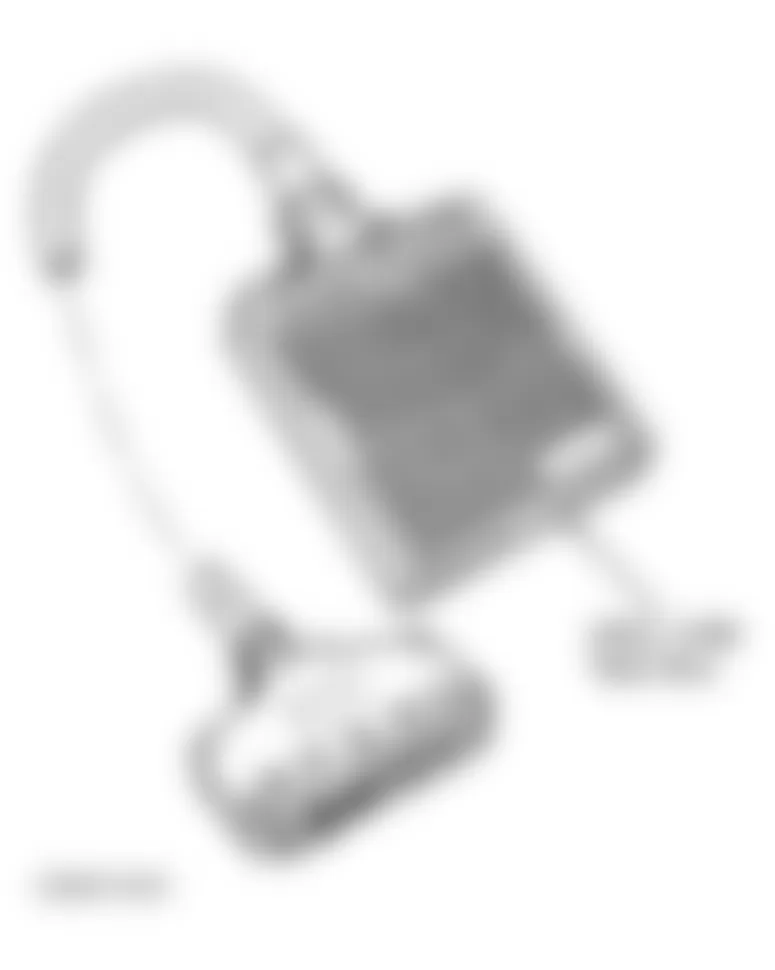
- Locate Data Link Connector (DLC) located behind cover under left side of steering column. See Fig. 1 . Connect VAG 1551 scan tool or generic scan tool to DLC. Turn ignition on or start engine and let it idle. If engine will not start, crank engine for at least 6 seconds. See appropriate table under DTC IDENTIFICATION .
- If no communication is possible with PCM, verify connection for scan tool is okay. If scan tool connection is okay, check wiring harness between DLC and PCM for open or short circuit. See WIRING DIAGRAMS article. Repair as necessary. On A4, PCM is located in left rear corner of engine compartment inside electrical box. On Cabriolet, PCM is located in floor cavity under passenger side carpeting. On all models, if wiring harness is okay, PCM is possibly faulty. See PCM VOLTAGE CHECK .

Fig. 1: Audi Cabriolet 1998 - Component Locations - Locating Data Link Connector (DLC)
Audi Cabriolet 1998 - CLEARING CODES
NOTE: It is necessary to generate a PCM readiness code if PCM memory is cleared, battery voltage is disconnected or PCM is disconnected. If PCM was replaced, see PCM REPLACING .
NOTE: Manufacturer does not provide information for using a generic scan tool to clear codes.
Audi Cabriolet 1998 - A4
VAG 1551 scan tool is necessary for clearing codes. Follow scan tool prompts for clearing codes. After clearing codes, it is necessary to generate a PCM readiness code. A PCM readiness code resets 8 specific values to zero. Follow scan tool prompts for generating a PCM readiness code.
Audi Cabriolet 1998 - Cabriolet
- VAG 1551 scan tool is necessary for clearing codes. Follow scan tool prompts for clearing codes. After clearing codes, it is necessary to generate a PCM readiness code.
- A PCM readiness code resets specific values to zero. To generate a readiness code, a mixed city and highway drive cycle must be performed. Vehicle must travel for 1.5-5.0 minutes at speeds of 50-63 MPH (with a 5-8 second deceleration) with manual transmission in 4th or 5th gear or automatic transmission shift lever in 4th position.
- If vehicle altitude is 5906 feet or more, a readiness code cannot be generated until vehicle is taken to a lower altitude. Follow scan tool prompts for generating a PCM readiness code.
Audi Cabriolet 1998 - PCM VOLTAGE CHECK
NOTE: When Powertrain Control Module (PCM) connectors are disconnected, all Diagnostic Trouble Codes (DTCs) will be erased. It is necessary to use VAG 1598 test box and Digital Volt/Ohm Meter (DVOM) to perform voltage check.
NOTE: It is necessary to generate a PCM readiness code if PCM memory is cleared, battery voltage is disconnected or PCM is disconnected. See CLEARING CODES under SELF-DIAGNOSTIC SYSTEM.
Audi Cabriolet 1998 - VOLTAGE CHECK (1.8L TURBO)
- Turn ignition off. Check fuse for Powertrain Control Module (PCM). Replace as necessary. Disconnect PCM connectors. PCM is located in left rear corner of engine compartment inside electrical box. Connect VAG 1598/22 test box to PCM wiring harness. See Fig. 2 .
- Connect DVOM to test box sockets No. 3 (B+) and 2 (GND). Voltage should be 10-14.5 volts. If voltage is within specification, go to next step. If voltage is not within specification, repair wiring as necessary. See WIRING DIAGRAMS article.
- Connect DVOM between test box sockets No. 1 (B+) and 2 (GND). Voltage should be 10-14.5 volts. If voltage is within specification, voltage supply is okay. If voltage is not within specification, repair wiring harness as necessary. See WIRING DIAGRAMS article.
Audi Cabriolet 1998 - VOLTAGE CHECK (2.8L A4)
- Turn ignition off. Check fuse for Powertrain Control Module (PCM). Replace as necessary. Disconnect PCM connectors. PCM is located in left rear corner of engine compartment inside electrical box. Connect VAG 1598/22 test box to PCM wiring harness. See Fig. 2 .
- Connect DVOM to test box sockets No. 3 (B+) and 2 (GND). Voltage should be 10-14.5 volts. If voltage is within specification, go to next step. If voltage is not within specification, repair wiring as necessary. See WIRING DIAGRAMS article.
- Connect DVOM between test box sockets No. 1 (B+) and 2 (GND). Voltage should be 10-14.5 volts. If voltage is within specification, voltage supply is okay. If voltage is not within specification, repair wiring harness as necessary. See WIRING DIAGRAMS article.
Audi Cabriolet 1998 - VOLTAGE CHECK (2.8L CABRIOLET)
- Turn ignition off. Check fuse for Powertrain Control Module (PCM). Replace as necessary. Disconnect PCM connectors. PCM is located in floor cavity, under carpet on passenger side of vehicle. Connect VAG 1598/19 test box to PCM wiring harness. See Fig. 2 .
- Connect VAG 1527B voltage tester between test box socket No. 10 and ground. Voltage tester should light. If voltage tester lights, go to next step. If voltage tester does not light, repair open circuit as necessary. See WIRING DIAGRAMS article.
- Connect VAG 1527B voltage tester between test box sockets No. 10 (B+) and A19, D3, D7, E3, E7 and E1 one at a time. Voltage tester should light. If voltage tester lights, voltage supply is okay. If voltage tester does not light, repair open between battery supply and test box socket No. 10. See WIRING DIAGRAMS article.
Fig. 2: Audi Cabriolet 1998 - Component Locations - Identifying VAG 1598 Test Box
Audi Cabriolet 1998 - MIL CHECK
NOTE: When Powertrain Control Module (PCM) connectors are disconnected, all Diagnostic Trouble Codes (DTCs) will be erased. It is necessary to use VAG 1598 test box to perform procedures.
NOTE: It is necessary to generate a PCM readiness code if PCM memory is cleared, battery voltage is disconnected or PCM is disconnected. See CLEARING CODES under SELF-DIAGNOSTIC SYSTEM.
NOTE: MIL check should only be performed if MIL is on continuously and no DTCs are stored or MIL never illuminates.
Audi Cabriolet 1998 - A4
- Turn ignition on. MIL should light. If MIL lights, go to step 5). If MIL does not light, go to next step.
- MIL is not lighting due to faulty wiring or an open circuit. Turn ignition off. Disconnect Powertrain Control Module (PCM) connectors. PCM is located in left rear corner of engine compartment inside electrical box. Connect VAG 1598/22 test box to PCM wiring harness. See Fig. 2 .
- Connect a jumper wire between test box sockets No. 2 and 17. Turn ignition on. MIL should light. If MIL does not light, go to next step.
- Turn ignition off. Inspect MIL bulb. If bulb is okay, check for an open circuit between MIL and PCM. See WIRING DIAGRAMS article. If wiring is okay, replace faulty PCM. See PCM REPLACING .
- Start engine and let it idle. MIL should go out after a few seconds. If MIL goes out, MIL is functioning properly. If MIL does not go out, check for any stored DTCs. See RETRIEVING CODES under SELF-DIAGNOSTIC SYSTEM. If DTCs are stored, repair as necessary. If no DTCs are stored, go to next step.
- MIL is on continuously due to a short to ground. Turn ignition off. Disconnect Powertrain Control Module (PCM) connectors. Connect VAG 1598/22 test box to PCM wiring harness. See Fig. 2 .
- Connect a DVOM between test box socket No. 17 and ground. DVOM should indicate infinity (no resistance). If DVOM reading is not as specified, go to next step. If DVOM reading is as specified, go to step 9).
- Check for a short circuit between MIL and Powertrain Control Module (PCM). See WIRING DIAGRAMS article.
- If no continuity is present and there is no short to ground, replace faulty PCM. See PCM REPLACING .
Audi Cabriolet 1998 - CABRIOLET
- Turn ignition on. MIL should light. If MIL lights, go to step 3). If MIL does not light, go to next step.
- MIL is not lighting due to faulty wiring or an open circuit. Turn ignition off. Inspect MIL bulb. If bulb is okay, check wiring between MIL and PCM. PCM is located in floor cavity under passenger side carpeting. See WIRING DIAGRAMS article. If wiring is okay, replace faulty PCM. See PCM REPLACING .
- Start engine and let it idle. MIL should go out after a few seconds. If MIL goes out, MIL is functioning properly. If MIL does not go out, check for any stored DTCs. See RETRIEVING CODES under SELF-DIAGNOSTIC SYSTEM. If DTCs are stored, repair as necessary. If no DTCs are stored, go to next step.
- MIL is on continuously due to a short to ground. Turn ignition off. Check for a short circuit between MIL and Powertrain Control Module (PCM). See WIRING DIAGRAMS article. Repair as necessary. If wiring is okay, replace faulty PCM. See PCM REPLACING .
Audi Cabriolet 1998 - PCM REPLACING
NOTE: On A4, when using Volkswagen Audi Group (VAG) 1551 scan tool, follow manufacturer's instructions for operation. VAG 1551 scan tool is necessary to perform adaptation of throttle valve control module to PCM.
NOTE: It is only necessary to perform this procedure when installing a NEW PCM in vehicle.
Audi Cabriolet 1998 - A4
- PCM is located in left rear corner of engine compartment inside electronics box. Code PCM. See PCM CODING . After coding PCM, verify no DTCs are stored in memory. Ensure throttle valve is in closed throttle position.
- Connect VAG 1551 scan tool to Data Link Connector (DLC). Following manufacturer's instructions, access Basic Setting 60 information using VAG 1551 scan tool. After confirming correct VAG 1551 scan tool display, "adaptation" will begin with ignition on and engine off.
- PCM will learn the closed throttle position, Wide Open Throttle (WOT), and other positions of throttle valve control module. PCM will store these values in permanent memory. Vehicle may idle unevenly and there may be a temporary loss of driveability until PCM has completed a learning process. PCM will not complete learn function if a DTC is stored in memory.
- Using VAG 1551, generate a PCM readiness code. A PCM readiness code resets 8 specific values to zero. Follow scan tool prompts for generating a PCM readiness code.
Audi Cabriolet 1998 - CABRIOLET
- PCM is located in floor cavity, under carpet on passenger side of vehicle. Code PCM. See PCM CODING . After coding PCM, verify no DTCs are stored in memory. Vehicle may idle unevenly and there may be a temporary loss of driveability until PCM has completed a learning process. PCM will not complete learn function if a DTC is stored in memory.
- Using VAG 1551, generate a PCM readiness code. A PCM readiness code resets specific values to zero. To generate a readiness code, a mixed city and highway drive cycle must be performed. Vehicle must travel for 1.5-5 minutes at speeds of 50-63 MPH (with a 5-8 second deceleration) with manual transmission in 4th or 5th gear or automatic transmission shift lever in 4th position.
- If vehicle altitude is 5906 feet or more, a readiness code cannot be generated until vehicle is taken to a lower altitude. Follow scan tool prompts for generating a PCM readiness code.
Audi Cabriolet 1998 - PCM CODING
NOTE: When using Volkswagen Audi Group (VAG) 1551 scan tool, follow manufacturer's instructions for operation. VAG 1551 scan tool is necessary to perform PCM coding.
If Powertrain Control Module (PCM) is replaced, it is necessary to code new PCM. If new PCM is not properly coded, the following problems may occur:
- Driveability problems (i.e., harsh shifting).
- False malfunctions stored in PCM memory.
- Increased fuel consumption.
- Increased exhaust emissions.
- Reduction in transmission life.
- All PCM functions are not carried out (i.e., EVAP system operation).
Connect VAG 1551 scan tool to Data Link Connector (DLC). Following manufacturer's instructions, access PCM coding information using VAG 1551 scan tool. For PCM coding options, see appropriate PCM CODING OPTIONS table.
As an example, a properly coded PCM for an A4 model with Front Wheel Drive (FWD) without traction control and 5-speed manual transmission would look like 06001 on the VAG 1551 scan tool.
NOTE: After coding PCM and starting engine for first time, allow engine to idle for several minutes so PCM can go through a learn function. Idle speed may be erratic while PCM is learning.
Audi Cabriolet 1998 PCM CODING OPTIONS
Application/Code Option Country/Emissions 06 USA Equipped With EVAP Leak Detection Pump 0 Front Wheel Drive Without Traction Control 1 Front Wheel Drive With Traction Control 2 All Wheel Drive Without Traction Control 3 All Wheel Drive With Traction Control Transmission 0 5-Speed Manual Transmission 5 Automatic Transmission 01V Vehicle Type 1 A4
Audi Cabriolet 1998 PCM CODING OPTIONS
Application/Code Option Country/Emissions 06 USA Equipped With EVAP Leak Detection Pump 0 Front Wheel Drive Without Traction Control 1 Front Wheel Drive With Traction Control 2 All Wheel Drive Without Traction Control 3 All Wheel Drive With Traction Control Transmission 0 5-Speed Manual Transmission 5 Automatic Transmission 01V Vehicle Type
Audi Cabriolet 1998 PCM CODING OPTIONS
Application/Code Option Country/Emissions 01 Vehicle With Exhaust Gas Recirculation (EGR) Drive/Auxiliary Function 0 Front Wheel Drive Without Traction Control 1 Front Wheel Drive With Traction Control Transmission 3 Automatic Transmission 01N Vehicle Type 4 Cabriolet
Audi Cabriolet 1998 - TEST DRIVE
NOTE: This procedure does not apply to A4.
Audi Cabriolet 1998 - CABRIOLET
Clear Diagnostic Trouble Codes (DTCs). See CLEARING CODES under SELF-DIAGNOSTIC SYSTEM. Turn ignition off. Start engine. Drive vehicle for at least 10 minutes. Check for any stored DTCs. If DTC sets again, perform testing procedure again. Repair vehicle as necessary.
Audi Cabriolet 1998 - DTC IDENTIFICATION
NOTE: Vehicle manufacturer does not support diagnostic information using aftermarket scan tools. Limited diagnostic information is available.
Audi Cabriolet 1998 A4 1.8L TURBO DTC IDENTIFICATION
Generic Scan Tool Code VAG 1551 Code Malfunction/Affected Sensor Or Circuit P0102 (1) (1) 16486 MAF Circuit Low Input P0103 (1) (1) 16487 MAF Circuit High Input P0107 (1) (1) 16491 MAP Or Barometric Pressure Low Input P0108 (1) (1) 16491 MAP Or Barometric Pressure High Input P0112 (1) (1) 16496 Intake Air Temp Circuit Low Input P0113 (1) (1) 16497 Intake Air Temp Circuit High Input P0116 (1) (1) 16500 ECT Circuit Range/Performance Problem P0117 (1) (1) 16501 ECT Circuit Low Input P0118 (1) (1) 16502 ECT Circuit High Input P0121 (1) (1) 16505 TP Sensor Circuit Range/Performance Problem P0122 (1) (1) 16506 TP Sensor Circuit Low Input P0123 (1) (1) 16507 TP Sensor Circuit High Input P0130 (1) (1) 16514 HO2S Circuit Malfunction (Bank 1, Sensor 1) P0131 (1) (1) 16515 HO2S Circuit Low Voltage (Bank 1, Sensor 1) P0132 (1) (1) 16516 HO2S Circuit High Voltage (Bank 1, Sensor 1) P0133 (2) (2) 16517 HO2S Circuit Slow Response (Bank 1, Sensor 1) P0134 (1) (1) 16518 HO2S Circuit No Activity Detected (Bank 1, Sensor 1) P0136 (1) (1) 16520 HO2S Circuit Malfunction (Bank 1, Sensor 2) P0137 (1) (1) 16521 HO2S Circuit Low Voltage (Bank 1, Sensor 2) P0140 (1) (1) 16524 HO2S Circuit No Activity Detected (Bank 1, Sensor 2) P0300 (2) (2) 16684 Random/Multiple Cylinder Misfire Detected P0301 (2) (2) 16685 Cylinder No. 1 Misfire Detected P0302 (2) (2) 16686 Cylinder No. 2 Misfire Detected P0303 (2) (2) 16687 Cylinder No. 3 Misfire Detected P0304 (2) (2) 16688 Cylinder No. 4 Misfire Detected P0321 (1) (1) 16705 Ignition/Distributor Engine Speed Input Circuit Range/Performance P0322 (3) (3) 16706 Ignition/Distributor Engine Speed Input Circuit No Signal P0327 (3) (3) 16711 Knock Sensor No. 1 Circuit Low Input P0332 (3) (3) 16716 Knock Sensor No. 2 Circuit Low Input P0422 (1) (1) 16806 Main Catalyst Efficiency Below Threshold (Bank 1) P0441 (1) (1) 16825 EVAP System Incorrect Purge Flow P0442 (1) (1) 16826 EVAP System Small Leak Detected P0455 (1) (1) 16839 EVAP System Gross Leak Detected P0501 (1) (1) 16885 Vehicle Speed Sensor Range/Performance P0506 (1) (1) 16890 Idle Control System RPM Lower Than Expected P0507 (1) (1) 16891 Idle Control System RPM Higher Than Expected P0560 (1) (1) 16944 System Voltage Malfunction P0562 (1) (1) 16946 System Voltage Low P0563 (1) (1) 16947 System Voltage High P0601 (1) (1) 16895 PCM Memory Check Sum Error P0604 (1) (1) 16988 PCM Random Access Memory (RAM) Error P0707 (4) (4) 17091 Transmission Range Sensor Circuit Low Input P0708 (4) (4) 17092 Transmission Range Sensor Circuit High Input P1102 (1) (1) 17510 HO2S Heater Circuit Short to B+ (Bank 1, Sensor 1) P1105 (1) (1) 17513 HO2S Heater Circuit Short to B+ (Bank 1, Sensor 2) P1127 (1) (1) 17535 Long Term Fuel Trim (Multiplicative) Too Rich (Bank 1) P1128 (1) (1) 17536 Long Term Fuel Trim (Multiplicative) Too Lean (Bank 1) P1136 (1) (1) 17544 Long Term Fuel Trim (Additive) Too Lean (Bank 1) P1137 (1) (1) 17545 Long Term Fuel Trim (Additive) Too Rich (Bank 1) P1176 (1) (1) 17584 HO2S Correction Behind Catalyst Limit Attained (Bank 1) P1196 (1) (1) 17604 HO2S Heater Electrical Malfunction (Bank 1, Sensor 1) P1198 (1) (1) 17606 HO2S Heater Electrical Malfunction (Bank 1, Sensor 2) P1213 (3) (3) 17621 Cylinder No. 1 Fuel Injector Circuit Short To B+ P1214 (3) (3) 17622 Cylinder No. 2 Fuel Injector Circuit Short To B+ P1215 (3) (3) 17623 Cylinder No. 3 Fuel Injector Circuit Short To B+ P1216 (3) (3) 17624 Cylinder No. 4 Fuel Injector Circuit Short To B+ P1225 (3) 17633 Cylinder No. 1 Fuel Injector Circuit Short To Ground P1226 (3) (3) 17634 Cylinder No. 2 Fuel Injector Circuit Short To Ground P1227 (3) (3) 17635 Cylinder No. 3 Fuel Injector Circuit Short To Ground P1228 (3) (3) 17636 Cylinder No. 4 Fuel Injector Circuit Short To Ground P1237 (3) (3) 17645 Cylinder No. 1 Fuel Injector Open Circuit P1238 (3) (3) 17646 Cylinder No. 2 Fuel Injector Open Circuit P1239 (3) (3) 17647 Cylinder No. 3 Fuel Injector Open Circuit P1240 (3) (3) 17648 Cylinder No. 4 Fuel Injector Open Circuit P1250 (4) (4) 17658 Fuel Level Too Low P1325 (4) (4) 17733 Cylinder No. 1 Knock Control Limit Attained P1326 (4) (4) 17734 Cylinder No. 2 Knock Control Limit Attained P1327 (4) (4) 17735 Cylinder No. 3 Knock Control Limit Attained P1328 (4) (4) 17736 Cylinder No. 4 Knock Control Limit Attained P1337 (1) (1) 17745 Camshaft Position Sensor Short To Ground (Bank 1) P1338 (1) (1) 17746 Camshaft Position Sensor Open Circuit Or Short To B+ (Bank 1) P1386 (4) (4) 17794 PCM Knock Control Circuit Error P1410 (1) (1) 17818 Fuel Tank Ventilation Valve Circuit Short To B+ P1425 (1) (1) 17833 Fuel Tank Ventilation Valve Short To Ground P1426 (1) (1) 17834 Fuel Tank Ventilation Valve Open P1471 (1) (1) 17879 EVAP Leak Detection Pump Short To B+ P1472 (1) (1) 17880 EVAP Leak Detection Pump Short To Ground P1473 (1) (1) 17881 EVAP Leak Detection Pump Open Circuit P1475 (1) (1) 17883 EVAP Leak Detection Pump Malfunction/Signal Circuit Open P1476 (1) (1) 17884 EVAP Leak Detection Pump Malfunction/Insufficient Vacuum P1477 (1) (1) 17885 EVAP Leak Detection Pump Malfunction P1500 (3) (3) 17908 Fuel Pump Relay Circuit Electrical Malfunction P1501 (3) (3) 17909 Fuel Pump Relay Circuit Short To Ground P1502 (3) (3) 17910 Fuel Pump Relay Circuit Short To B+ P1505 (1) (1) 17913 CTP Switch Does Not Close (Open Circuit) P1506 (1) (1) 17914 CTP Switch Does Not Open (Short To Ground) P1543 (3) (3) 17951 Throttle Actuation Potentiometer Signal Too Low P1544 (3) (3) 17952 Throttle Actuation Potentiometer Signal Too High P1545 (1) (1) 17953 Throttle Position Control Malfunction P1546 (4) (4) 17954 Boost Pressure Control Valve Short To B+ P1547 (4) (4) 17955 Boost Pressure Control Valve Short To Ground P1548 (4) (4) 17956 Boost Pressure Control Valve Open P1555 (4) (4) 17963 Charge Pressure Upper Limit Exceeded P1556 (4) (4) 17964 Charge Pressure Negative Deviation P1557 (4) (4) 17965 Charge Pressure Positive Deviation P1558 (1) (1) 17966 Throttle Actuator Electrical Malfunction P1559 (4) (4) 17967 Idle Speed Control/Throttle Position Adaptation Malfunction P1560 (4) (4) 17968 Maximum Engine Speed Exceeded P1602 (4) (4) 18010 Power Supply (B+) Terminal 30 Low Voltage P1606 (4) (4) 18014 Rough Road Specification Engine Torque ABS-ECU Electrical Malfunction P1611 (1) (1) 18019 MIL Call-Up Circuit/TCM Short To Ground P1612 (4) (4) 18020 PCM Incorrect Coding P1613 (5) (5) 18021 MIL Call-Up Circuit Open Or Short To B+ P1624 (6) (6) 18032 MIL Request Active P1640 (1) (1) 18048 Internal PCM (EEPROM) Error
(1) MIL is switched on after 2 trips.
(2) MIL is switched on after 2 trips or will blink.
(3) MIL is switched on immediately.
(4) MIL is not switched on.
(5) MIL is switched on after 2 trips. See TRANSMISSION SERVICE & REPAIR section.
(6) MIL is switched on immediately. See TRANSMISSION SERVICE & REPAIR section.
Audi Cabriolet 1998 A4 2.8L DTC IDENTIFICATION
Generic Scan Tool Code VAG 1551 Code Malfunction/Affected Sensor Or Circuit P0102 (1) (1) 16486 MAF Circuit Low Input P0103 (1) (1) 16487 MAF Circuit High Input P0112 (1) (1) 16496 Intake Air Temperature Circuit Low Input P0113 (1) (1) 16497 Intake Air Temperature Circuit High Input P0116 (1) (1) 16500 ECT Circuit Range/Performance Problem P0117 (1) (1) 16501 ECT Circuit Low Input P0118 (1) (1) 16502 ECT Circuit High Input P0121 (1) (1) 16505 TP Sensor Circuit Range/Performance Problem P0122 (1) (1) 16506 TP Sensor Circuit Low Input P0123 (1) (1) 16507 TP Sensor Circuit High Input P0130 (1) (1) 16514 HO2S Circuit Malfunction (Bank 1, Sensor 1) P0131 (1) (1) 16515 HO2S Circuit Low Voltage (Bank 1, Sensor 1) P0132 (1) (1) 16516 HO2S Circuit High Voltage (Bank 1, Sensor 1) P0133 (1) (1) 16517 HO2S Circuit Slow Response (Bank 1, Sensor 1) P0134 (1) (1) 16518 HO2S Circuit No Activity Detected (Bank 1, Sensor 1) P0136 (1) (1) 16520 HO2S Circuit Malfunction (Bank 1, Sensor 2) P0137 (1) (1) 16521 HO2S Circuit Low Voltage (Bank 1, Sensor 2) P0138 (1) (1) 16522 HO2S Circuit High Voltage (Bank 1, Sensor 2) P0140 (1) (1) 16524 HO2S Circuit No Activity Detected (Bank 1, Sensor 2) P0150 (1) (1) 16534 HO2S Circuit Malfunction (Bank 2, Sensor 1) P0151 (1) (1) 16535 HO2S Circuit Low Voltage (Bank 2, Sensor 1) P0152 (1) (1) 16536 HO2S Circuit High Voltage (Bank 2, Sensor 1) P0153 (1) (1) 16537 HO2S Circuit Slow Response (Bank 2, Sensor 1) P0154 (1) (1) 16538 HO2S Circuit No Activity Detected (Bank 2, Sensor 1) P0156 (1) (1) 16540 HO2S Circuit Malfunction (Bank 2, Sensor 2) P0157 (1) (1) 16541 HO2S Circuit Low Voltage (Bank 2, Sensor 2) P0158 (1) (1) 16542 HO2S Circuit High Voltage (Bank 2, Sensor 2) P0160 (1) (1) 16544 HO2S Circuit No Activity Detected (Bank 2, Sensor 2) P0300 (2) (2) 16684 Random/Multiple Misfire Detected P0301 (2) (2) 16685 Cylinder No. 1 Misfire Detected P0302 (2) (2) 16686 Cylinder No. 2 Misfire Detected P0303 (2) (2) 16687 Cylinder No. 3 Misfire Detected P0304 (2) (2) 16688 Cylinder No. 4 Misfire Detected P0305 (2) (2) 16689 Cylinder No. 5 Misfire Detected P0306 (2) (2) 16690 Cylinder No. 6 Misfire Detected P0321 (1) (1) 16705 Ignition Engine Speed Input Circuit Range/Performance P0322 (3) (3) 16706 Ignition Engine Speed Input Circuit No Signal P0327 (3) (3) 16711 Knock Sensor No. 1 Circuit Low Input P0328 (3) (3) 16712 Knock Sensor No. 1 Circuit High Input P0332 (3) (3) 16716 Knock Sensor No. 2 Circuit Low Input P0333 (3) (3) 16717 Knock Sensor No. 2 Circuit High Input P0411 (1) (1) 16795 Secondary Air Injection System Incorrect Flow Detected P0422 (1) (1) 16806 Main Catalyst Efficiency Below Threshold (Bank 1) P0432 (1) (1) 16816 Main Catalyst Efficiency Below Threshold (Bank 2) P0441 (4) (4) 16825 EVAP Emission Control System Incorrect Purge Flow P0442 (4) (4) 16826 EVAP Emission Control System Small Leak Detected P0455 (4) (4) 16839 EVAP Emission Control System Gross Leak Detected P0501 (1) (1) 16885 Vehicle Speed Sensor Range/Performance P0506 (1) (1) 16890 Idle Control System RPM Lower Than Expected P0507 (1) (1) 16891 Idle Control System RPM Higher Than Expected P0601 (1) (1) 16985 Internal Controller Module Memory Check Sum Error P0604 (1) (1) 16988 Internal Controller Module Memory RAM Error P1102 (1) (1) 17510 HO2S Heater Circuit Short to B+ (Bank 1, Sensor 1) P1105 (1) (1) 17513 HO2S Heater Circuit Short to B+ (Bank 1, Sensor 2) P1107 (1) (1) 17515 HO2S Heater Circuit Short To B+ (Bank 2, Sensor 1) P1110 (1) (1) 17518 HO2S Heater Circuit Short To B+ (Bank 2, Sensor 2) P1127 (1) (1) 17535 Long Term Fuel Trim Multiplicative Too Rich (Bank 1) P1128 (1) (1) 17536 Long Term Fuel Trim Multiplicative Too Lean (Bank 1) P1129 (1) (1) 17537 Long Term Fuel Trim Multiplicative Too Rich (Bank 2) P1130 (1) (1) 17538 Long Term Fuel Trim Multiplicative Too Lean (Bank 2) P1136 (1) (1) 17544 Long Term Fuel Trim Additive Too Lean (Bank 1) P1137 (1) (1) 17545 Long Term Fuel Trim Additive Too Rich (Bank 1) P1138 (1) (1) 17546 Long Term Fuel Trim Additive Too Lean (Bank 2) P1139 (1) (1) 17547 Long Term Fuel Trim Additive Too Rich (Bank 2) P1141 (1) (1) 17549 Load Calculation Cross Check Range/Performance P1176 (4) (4) 17584 O2 Correction Behind Catalyst B1 Limit Attained P1177 (4) (4) 17585 O2 Correction Behind Catalyst B2 Limit Attained P1196 (1) (1) 17604 O2 Sensor Heater Circuit Electrical Malfunction (Bank 1, Sensor 1) P1197 (1) (1) 17605 O2 Sensor Heater Circuit Electrical Malfunction (Bank 2, Sensor 1) P1198 (1) (1) 17606 O2 Sensor Heater Circuit Electrical Malfunction (Bank 1, Sensor 2) P1199 (1) (1) 17607 O2 Sensor Heater Circuit Electrical Malfunction (Bank 2, Sensor 2) P1213 (3) (3) 17621 Cylinder No. 1 Fuel Injector Circuit Short To B+ P1214 (3) (3) 17622 Cylinder No. 2 Fuel Injector Circuit Short To B+ P1215 (3) (3) 17623 Cylinder No. 3 Fuel Injector Circuit Short To B+ P1216 (3) (3) 17624 Cylinder No. 4 Fuel Injector Circuit Short To B+ P1217 (3) (3) 17625 Cylinder No. 5 Fuel Injector Circuit Short To B+ P1218 (3) (3) 17626 Cylinder No. 6 Fuel Injector Circuit Short To B+ P1225 (3) (3) 17633 Cylinder No. 1 Fuel Injector Circuit Short To Ground P1226 (3) (3) 17634 Cylinder No. 2 Fuel Injector Circuit Short To Ground P1227 (3) (3) 17635 Cylinder No. 3 Fuel Injector Circuit Short To Ground P1228 (3) (3) 17636 Cylinder No. 4 Fuel Injector Circuit Short To Ground P1229 (3) (3) 17637 Cylinder No. 5 Fuel Injector Circuit Short To Ground P1230 (3) (3) 17638 Cylinder No. 6 Fuel Injector Circuit Short To Ground P1237 (3) (3) 17645 Cylinder No. 1 Fuel Injector Open Circuit P1238 (3) (3) 17646 Cylinder No. 2 Fuel Injector Open Circuit P1239 (3) (3) 17647 Cylinder No. 3 Fuel Injector Open Circuit P1240 (3) (3) 17648 Cylinder No. 4 Fuel Injector Open Circuit P1241 (3) (3) 17649 Cylinder No. 5 Fuel Injector Open Circuit P1242 (3) (3) 17650 Cylinder No. 6 Fuel Injector Open Circuit P1250 (4) (4) 17658 Fuel Level Too Low P1325 (4) (4) 17733 Cylinder No. 1 Knock Control Limit Attained P1326 (4) (4) 17734 Cylinder No. 2 Knock Control Limit Attained P1327 (4) (4) 17735 Cylinder No. 3 Knock Control Limit Attained P1328 (4) (4) 17736 Cylinder No. 4 Knock Control Limit Attained P1329 (4) (4) 17737 Cylinder No. 5 Knock Control Limit Attained P1330 (4) (4) 17738 Cylinder No. 6 Knock Control Limit Attained P1337 (1) (1) 17745 Camshaft Position Sensor Short To Ground (Bank 1) P1338 (1) (1) 17746 Camshaft Position Sensor Open Circuit Or Short To B+ (Bank 1) P1386 (1) (1) 17794 Internal Control Module Knock Control Circuit Error P1391 (1) (1) 17799 Camshaft Position (CMP) Sensor Short To Ground (Bank 2) P1392 (1) (1) 17800 Camshaft Position (CMP) Sensor Open Circuit Or Short To B+ (Bank 2) P1410 (1) (1) 17818 Fuel Tank Ventilation Valve Circuit Short To B+ P1421 (3) (3) 17829 Secondary Air Injection Valve Circuit Short To Ground P1422 (3) (3) 17830 Secondary Air Injection System Control Valve Circuit Short To B+ P1425 (1) (1) 17833 Tank Vent Valve Short To Ground P1426 (1) (1) 17834 Tank Vent Valve Open P1432 (1) (1) 17840 Secondary Air Injection Valve Open P1433 (1) (1) 17841 Secondary Air Injection System Pump Relay Circuit Open P1434 (1) (1) 17842 Secondary Air Injection System Pump Relay Circuit Short To B+ P1435 (1) (1) 17843 Secondary Air Injection System Pump Relay Circuit Short To Ground P1436 (1) (1) 17844 Secondary Air Injection System Pump Relay Circuit Electrical Malfunction P1471 (4) (4) 17879 EVAP Emission Control LDP Circuit Short To B+ P1472 (4) (4) 17880 EVAP Emission Control LDP Circuit Short To Ground P1473 (4) (4) 17881 EVAP Emission Control LDP Open Circuit P1476 (4) (4) 17884 EVAP Emission Control LDP Circuit Malfunction/Insufficient Vacuum P1477 (4) (4) 17885 EVAP Emission Control LDP Circuit Malfunction P1500 (3) (3) 17908 Fuel Pump Relay Circuit Electrical
Malfunction P1501 (3) (3) 17909 Fuel Pump Relay Circuit Short To Ground P1502 (3) (3) 17910 Fuel Pump Relay Circuit Short To B+ P1505 (1) (1) 17913 CTP Switch Does Not Close (Open Circuit) P1512 (3) (3) 17920 Intake Manifold Change-Over Valve Circuit Short To B+ P1515 (3) (3) 17923 Intake Manifold Change-Over Valve Circuit Short To Ground P1516 (3) (3) 17924 Intake Manifold Change-Over Valve Circuit Open P1519 (1) (1) 17927 Intake Camshaft Control Malfunction (Bank 1) P1522 (1) (1) 17930 Intake Camshaft Control Malfunction (Bank 2) P1543 (1) (1) 17951 Throttle Actuation Potentiometer Signal Too Low P1544 (1) (1) 17952 Throttle Actuation Potentiometer Signal Too High P1545 (1) (1) 17953 Throttle Position Control Malfunction P1558 (1) (1) 17966 Throttle Actuator Electrical Malfunction P1559 (4) (4) 17967 Idle Speed Control Throttle Position Adaptation Malfunction P1560 (4) (4) 17968 Maximum Engine Speed Exceeded P1564 (4) (4) 17972 Idle Speed Control Throttle Position Low Voltage During Adaptation P1565 (1) (1) 17973 Idle Speed Control Throttle Position Lower Impact Not Attained P1600 (3) (3) 18008 Power Supply (B+) Terminal 15 Low Voltage P1602 (4) (4) 18010 Power Supply (B+) Terminal 30 Low Voltage P1606 (4) (4) 18014 Rough Road/Acceleration Specification Engine Torque ABS-PCM Electrical Malfunction P1612 (3) (3) 18020 PCM Incorrectly Coded (Vehicle With A/T Is Coded For M/T) P1612 (4) (4) 18020 PCM Incorrectly Coded (Vehicle With ASR Is Not Coded For ASR) P1624 (3) (3) 18032 MIL Request Signal Active P1626 (1) (1) 18034 CAN Bus Missing Message From Transmission Controller P1640 (1) (1) 18048 Internal Controller Module (EEPROM) Error P1681 (3) (3) 18089 Controller Unit Programming Not Finished P1690 (4) (4) 18098 MIL Malfunction
(1) MIL is switched on after 2 trips.
(2) MIL is switched on after 2 trips or will blink.
(3) MIL is switched on immediately.
(4) MIL is not switched on.
Audi Cabriolet 1998 CABRIOLET DTC IDENTIFICATION
Generic Scan Tool Code VAG 1551 Code Malfunction/Affected Sensor Or Circuit P0102 (1) (1) 16486 MAF Circuit Low Input P0103 (1) (1) 16487 MAF Circuit High Input P0116 (1) (1) 16500 ECT Circuit Range/Performance Problem P0117 (1) (1) 16501 ECT Circuit Low Input P0118 (1) (1) 16502 ECT Circuit High Input P0120 (1) (1) 16504 TP Sensor Circuit Malfunction P0121 (1) (1) 16505 TP Sensor Circuit Range/Performance Problem P0122 (1) (1) 16506 TP Sensor Circuit Low Input P0123 (1) (1) 16507 TP Sensor Circuit High Input P0130 (1) (1) 16514 HO2S Circuit Malfunction (Bank 1, Sensor 1) P0132 (1) (1) 16516 HO2S Circuit High Voltage (Bank 1, Sensor 1) P0133 (2) (2) 16517 HO2S Circuit Slow Response (Bank 1, Sensor 1) P0134 (1) (1) 16518 HO2S Circuit No Activity Detected (Bank 1, Sensor 1) P0135 (1) (1) 16519 HO2S Heater Circuit Malfunction (Bank 1, Sensor 1) P0136 (1) (1) 16520 HO2S Circuit Malfunction (Bank 1, Sensor 2) P0138 (1) (1) 16522 HO2S Circuit High Voltage (Bank 1, Sensor 2) P0141 (1) (1) 16525 HO2S Heater Circuit Malfunction (Bank 1, Sensor 2) P0150 (1) (1) 16534 HO2S Circuit Malfunction (Bank 2, Sensor 1) P0152 (1) (1) 16536 HO2S Circuit High Voltage (Bank 2, Sensor 1) P0153 (2) (2) 16537 HO2S Circuit Slow Response (Bank 2, Sensor 1) P0154 (1) (1) 16538 HO2S Circuit No Activity Detected (Bank 2, Sensor 1) P0155 (1) (1) 16539 HO2S Heater Circuit Malfunction (Bank 2, Sensor 1) P0156 (1) (1) 16540 HO2S Circuit Malfunction (Bank 2, Sensor 2) P0158 (1) (1) 16542 HO2S Circuit High Voltage (Bank 2, Sensor 2) P0161 (1) (1) 16545 HO2S Heater Circuit Malfunction (Bank 2, Sensor 2) P0170 (2) (2) 16554 Fuel Trim Malfunction (Bank 1) P0171 (2) (2) 16555 Fuel Trim, System Too Lean (Bank 1) P0172 (2) (2) 16556 Fuel Trim, System Too Rich (Bank 1) P0173 (2) (2) 16557 Fuel Trim Malfunction (Bank 2) P0174 (2) (2) 16558 Fuel Trim, System Too Lean (Bank 2) P0175 (2) (2) 16559 Fuel Trim, System Too Rich (Bank 2) P0300 (3) (3) 16684 Random/Multiple Misfire Detected P0301 (3) (3) 16685 Cylinder No. 1 Misfire Detected P0302 (3) (3) 16686 Cylinder No. 2 Misfire Detected P0303 (3) (3) 16687 Cylinder No. 3 Misfire Detected P0304 (3) (3) 16688 Cylinder No. 4 Misfire Detected P0305 (3) (3) 16689 Cylinder No. 5 Misfire Detected P0306 (3) (3) 16690 Cylinder No. 6 Misfire Detected P0322 (1) (1) 16706 Ignition Engine Speed Input Circuit No Signal P0327 (1) (1) 16711 Knock Sensor No. 1 Circuit Low Input P0332 (1) (1) 16716 Knock Sensor No. 2 Circuit Low Input P0337 (1) (1) 16721 Crankshaft Position Sensor Circuit Low Input P0401 (2) (2) 16785 EGR Flow Insufficient Detected P0402 (2) (2) 16786 EGR Flow Excessive Detected P0422 (2) (2) 16806 Main Catalyst Efficiency Below Threshold (Bank 1) P0432 (2) (2) 16816 Main Catalyst Efficiency Below Threshold (Bank 2) P0440 (2) (2) 16824 EVAP System Malfunction P0452 (1) (1) 16836 EVAP System Pressure Sensor Low Input P0453 (1) (1) 16837 EVAP System Pressure Sensor High Input P0501 (1) (1) 16885 Vehicle Speed Sensor Range/Performance P0603 (4) (4) 65535 PCM Keep Alive Memory (KAM) Error P0605 (1) (1) 16989 PCM Read Only Memory (ROM) Error P0605 (4) (4) 65535 PCM Malfunction P0705 (4) (4) 00293 Transmission Range Sensor Circuit Malfunction P0707 (5) (5) 17091 Transmission Range Sensor Circuit Low Input P0715 (4) (4) 00297 Input/Turbine Speed Sensor Circuit Malfunction P0721 (4) (4) 00297 Output Speed Sensor Circuit Range/Performance P0722 (4) (4) 00297 Output Speed Sensor Circuit No Signal P0725 (4) (4) 00529 Engine Speed Input Circuit Malfunction P0726 (4) (4) 00543 Engine Speed Input Circuit Range/Performance P0727 (4) (4) 00529 Engine Speed Input Circuit No Signal P0730 (4) (4) 00652 Incorrect Gear Ratio P0731 (4) (4) 00652 Gear 1 Incorrect Ratio P0732 (4) (4) 00652 Gear 2 Incorrect Ratio P0733 (4) (4) 00652 Gear 3 Incorrect Ratio P0734 (4) (4) 00652 Gear 4 Incorrect Ratio P0748 (4) (4) 00268 Pressure Control Solenoid Electrical P0753 (4) (4) 00258 Shift Solenoid A Electrical P0758 (4) (4) 00260 Shift Solenoid B Electrical P0763 (4) (4) 00262 Shift Solenoid C Electrical P0768 (4) (4) 00264 Shift Solenoid D Electrical P0773 (4) (4) 00266 Shift Solenoid E Electrical P1101 (1) (1) 17509 HO2S Voltage Too Low/Air Leak (Bank 1, Sensor 1) P1102 (1) (1) 17510 HO2S Heater Circuit Short to B+ (Bank 1, Sensor 1) P1104 (1) (1) 17512 HO2S Voltage Too Low/Air Leak (Bank 1, Sensor 2) P1105 (1) (1) 17513 HO2S Heater Circuit Short To B+ (Bank 1, Sensor 2) P1106 (1) (1) 17514 HO2S Voltage Too Low/Air Leak (Bank 2, Sensor 1) P1107 (1) (1) 17515 HO2S Heater Circuit Short To B+ (Bank 2, Sensor 1) P1109 (1) (1) 17517 HO2S Voltage Too Low/Air Leak (Bank 2, Sensor 2) P1110 (1) (1) 17518 HO2S Heater Circuit Short To B+ (Bank 2, Sensor 2) P1201 (1) (1) 17609 Cylinder No. 1 Fuel Injector Circuit Electrical Malfunction P1202 (1) (1) 17610 Cylinder No. 2 Fuel Injector Circuit Electrical Malfunction P1203 (1) (1) 17611 Cylinder No. 3 Fuel Injector Circuit Electrical Malfunction P1204 (1) (1) 17612 Cylinder No. 4 Fuel Injector Circuit Electrical Malfunction P1205 (1) (1) 17613 Cylinder No. 5 Fuel Injector Circuit Electrical Malfunction P1206 (1) (1) 17614 Cylinder No. 6 Fuel Injector Circuit Electrical Malfunction P1213 (1) (1) 17621 Cylinder No. 1 Fuel Injector
Circuit Short To B+ P1214 (1) (1) 17622 Cylinder No. 2 Fuel Injector Circuit Short To B+ P1215 (1) (1) 17623 Cylinder No. 3 Fuel Injector Circuit Short To B+ P1216 (1) (1) 17624 Cylinder No. 4 Fuel Injector Circuit Short To B+ P1217 (1) (1) 17625 Cylinder No. 5 Fuel Injector Circuit Short To B+ P1218 (1) (1) 17626 Cylinder No. 6 Fuel Injector Circuit Short To B+ P1250 (5) (5) 17658 Fuel Level Too Low P1325 (5) (5) 17733 Cylinder No. 1 Knock Control Limit Attained P1326 (5) (5) 17734 Cylinder No. 2 Knock Control Limit Attained P1327 (5) (5) 17735 Cylinder No. 3 Knock Control Limit Attained P1328 (5) (5) 17736 Cylinder No. 4 Knock Control Limit Attained P1329 (5) (5) 17737 Cylinder No. 5 Knock Control Limit Attained P1330 (5) (5) 17738 Cylinder No. 6 Knock Control Limit Attained P1339 (1) (1) 17747 Crankshaft Position Sensor/Engine Speed Sensor Cross Connected P1341 (1) (1) 17749 Ignition Coil Power Output Stage 1 Short To Ground P1343 (1) (1) 17751 Ignition Coil Power Output Stage 2 Short To Ground P1345 (1) (1) 17753 Ignition Coil Power Output Stage 3 Short To Ground P1391 (1) (1) 17799 Camshaft Position (CMP) Sensor Short To Ground (Bank 2) P1392 (1) (1) 17800 Camshaft Position (CMP) Sensor Open Circuit Or Short To B+ (Bank 2) P1393 (1) (1) 17801 Ignition Coil Power Output Stage 1 Electrical Malfunction P1394 (1) (1) 17802 Ignition Coil Power Output Stage 2 Electrical Malfunction P1395 (1) (1) 17803 Ignition Coil Power Output Stage 3 Electrical Malfunction P1396 (1) (1) 17804 Engine Speed Sensor Missing Tooth P1400 (1) (1) 17808 EGR Valve Circuit Electrical Malfunction P1402 (1) (1) 17810 EGR Valve Circuit Short To B+ P1407 (1) (1) 17815 EGR Temperature Sensor Signal Too Low P1408 (1) (1) 17816 EGR Temperature Sensor Signal Too High P1409 (1) (1) 17817 Fuel Tank Ventilation Valve Circuit Electrical Malfunction P1410 (1) (1) 17818 Fuel Tank Ventilation Valve Circuit Short To B+ P1417 (5) (5) 17825 Fuel Level Sensor Signal Too Low P1418 (5) (5) 17826 Fuel Level Sensor Signal Too High P1500 (1) (1) 17908 Fuel Pump Relay Circuit Electrical Malfunction P1504 (1) (1) 17912 Intake Air System By-pass Leak Detected P1505 (1) (1) 17913 CTP Switch Does Not Close (Open Circuit) P1506 (1) (1) 17914 CTP Switch Does Not Open (Short To Ground) P1509 (1) (1) 17917 IAC Circuit Electrical Malfunction P1510 (1) (1) 17918 IAC Circuit Short To B+ P1511 (5) (5) 17919 Intake Manifold Change-Over
Valve Circuit Electrical Malfunction P1512 (5) (5) 17920 Intake Manifold Change-Over Valve Circuit Short To B+ P1600 (5) (5) 18008 Power Supply (B+) Terminal 15 Low Voltage P1602 (1) (1) 18010 Power Supply (B+) Terminal 30 Low Voltage P1606 (5) (5) 18014 Rough Road Specification Engine Torque ABS/PCM Electrical Malfunction P1611 (1) (1) 18019 MIL Call-Up/TCM Short To Ground P1612 (1) (1) 18020 PCM Incorrectly Coded P1613 (1) (1) 18021 MIL Call-Up Circuit Open Or Short To B+ P1711 (4) (4) 00283 Wheel Speed Signal No. 1 Range/Performance P1716 (4) (4) 00285 Wheel Speed Signal No. 2 Range/Performance P1726 (4) (4) 00290 Wheel Speed Signal No. 4 Range/Performance P1728 (4) (4) 00597 Different Wheel Speed Signals Range/Performance P1746 (4) (4) 00532 Transmission Control Module Relay Malfunction P1749 (4) (4) 01044 Transmission Control Module Relay Malfunction P1766 (4) (4) 00638 Throttle Angle Signal Stuck Off P1767 (4) (4) 00638 Throttle Angle Signal Stuck On P1778 (4) (4) 00270 Solenoid EV7 Electrical Malfunction P1780 (4) (4) 00545 Engine Intervention Readable
(1) MIL is switched on immediately.
(2) MIL is switched on after 2 trips.
(3) MIL is switched on after 2 trips or will blink.
(4) See TRANSMISSION SERVICE & REPAIR section.
(5) MIL is not switched on.
Audi Cabriolet 1998 - CONNECTOR IDENTIFICATION
Audi Cabriolet 1998 CONNECTOR IDENTIFICATION DIRECTORY
Connector See
Fig./TH> Camshaft Position Sensor Connector Terminals Fig. 3 ECT Sensor Connector Terminals Fig. 4 ECT Sensor Terminals Fig. 5 EGR Temperature Sensor Connector Terminals Fig. 6 EGR Vacuum Regulator Solenoid Valve Connector (Harness-Side) Terminals Fig. 6 Engine Speed Sensor Connector (Harness-Side) Terminals Fig. 3 Engine Speed Sensor Connector (Sensor-Side) Terminals Fig. 7 EVAP Canister Purge Valve Harness Connector Terminals Fig. 6 EVAP Differential Pressure Sensor Connector (Harness-Side) Terminals Fig. 3 EVAP Leak Detection Pump (Component-Side) Fig. 8 EVAP Leak Detection Pump (Harness-Side) Fig. 9 Fuel Injector Harness Connector Fig. 6 HO2S Black 2-Pin Heater Connector Fig. 6 HO2S Connector (Harness-Side) Terminals Fig. 10 HO2S Connector (Sensor-Side) Terminals Fig. 11 IAC Valve Connector Terminals Fig. 12 Ignition Coil Power Output Stage 3-Pin Connector (Harness-Side) Terminals Fig. 3 Ignition Coil Power Output Stage 4-Pin Connector (Harness-Side) Terminals Fig. 13 Intake Manifold Change-Over Valve Connector Terminals Fig. 6 Knock Sensor Connector (Harness-Side) Terminals Fig. 3 Knock Sensor Connector (Sensor-Side) Terminals Fig. 7 MAF Sensor Connector Terminals A4 (1.8L Turbo) Fig. 14 A4 (2.8L) & Cabriolet Fig. 3 Secondary Air Injection Solenoid Valve Harness Connector Fig. 6 TP Sensor Connector Terminals Fig. 15 TP Sensor Terminals Fig. 16 Throttle Valve Control Module (TVCM) Connector Terminals Fig. 17
Fig. 3: Audi Cabriolet 1998 - Component Locations - 3-Pin Harness Connector

Fig. 4: Audi Cabriolet 1998 - Component Locations - ECT Sensor Connector Terminals

Fig. 5: Audi Cabriolet 1998 - Component Locations - ECT Sensor Terminals

Fig. 6: Audi Cabriolet 1998 - Component Locations - 2-Pin Harness Connector
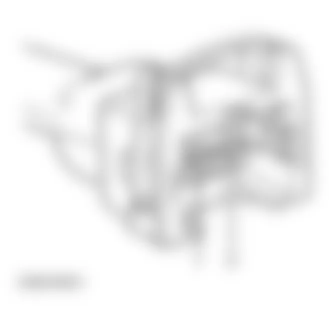
Fig. 7: Audi Cabriolet 1998 - Component Locations - 3-Pin Connector (Sensor-Side)
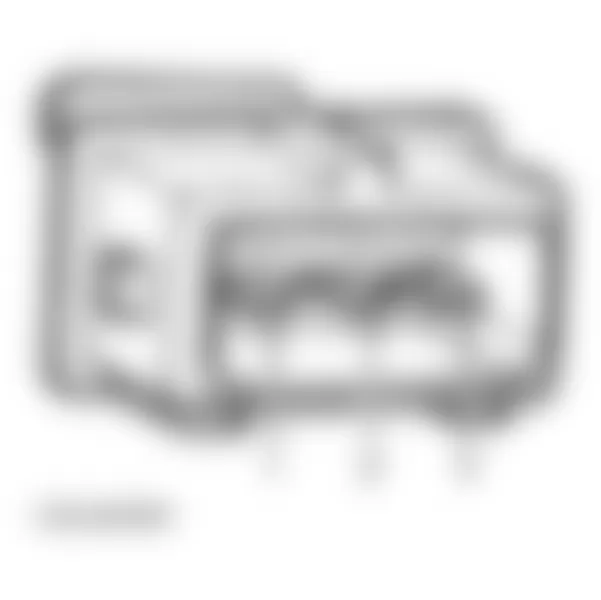
Fig. 8: Audi Cabriolet 1998 - Component Locations - EVAP Leak Detection Pump (Component-Side)

Fig. 9: Audi Cabriolet 1998 - Component Locations - EVAP Leak Detection Pump (Harness-Side)

Fig. 10: Audi Cabriolet 1998 - Component Locations - HO2S Connector (Harness-Side) Terminals

Fig. 11: Audi Cabriolet 1998 - Component Locations - HO2S Connector (Sensor-Side) Terminals

Fig. 12: Audi Cabriolet 1998 - Component Locations - IAC Valve Connector Terminals
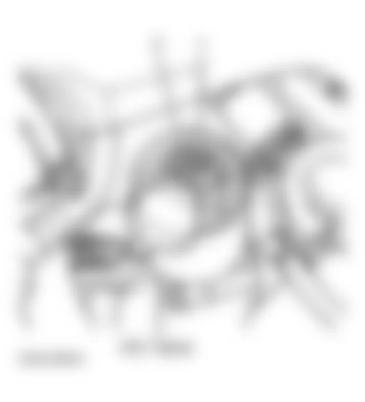
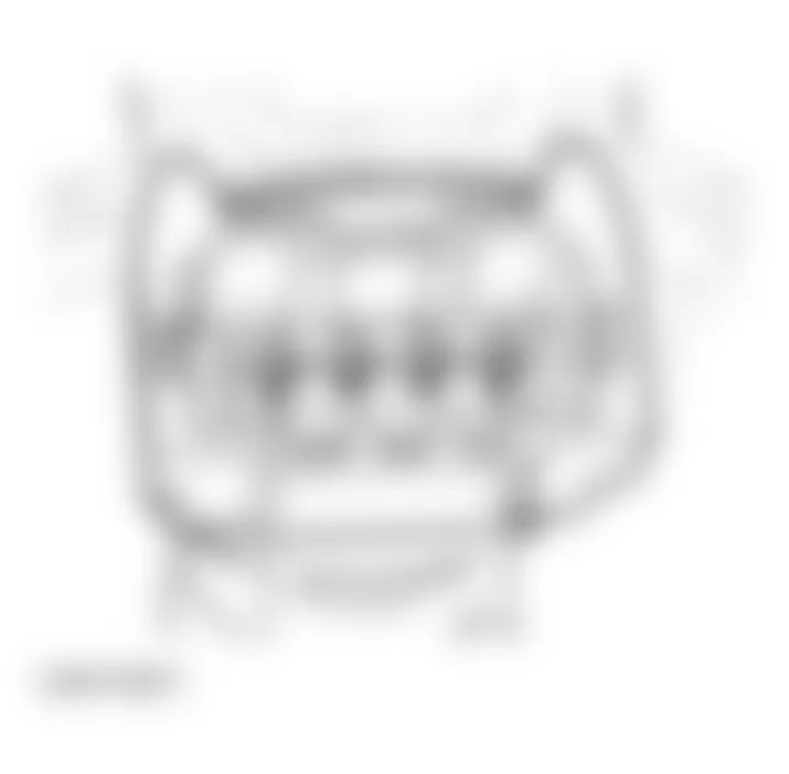
Fig. 14: Audi Cabriolet 1998 - Component Locations - MAF Sensor Connector Terminals (Harness-Side)

Fig. 15: Audi Cabriolet 1998 - Component Locations - TP Sensor Connector Terminals

Fig. 16: Audi Cabriolet 1998 - Component Locations - TP Sensor Terminals
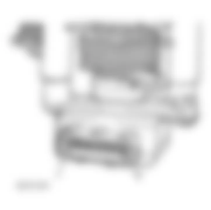
Fig. 17: Audi Cabriolet 1998 - Component Locations - TVCM Connector Terminals

Audi Cabriolet 1998 - SUMMARY
If no hard codes (or pass codes only) are present, driveability symptoms exist or intermittent codes exist, proceed to TESTS W/O CODES article for diagnosis by symptom (i.e., ROUGH IDLE, NO START, etc.) or intermittent diagnostic procedures.