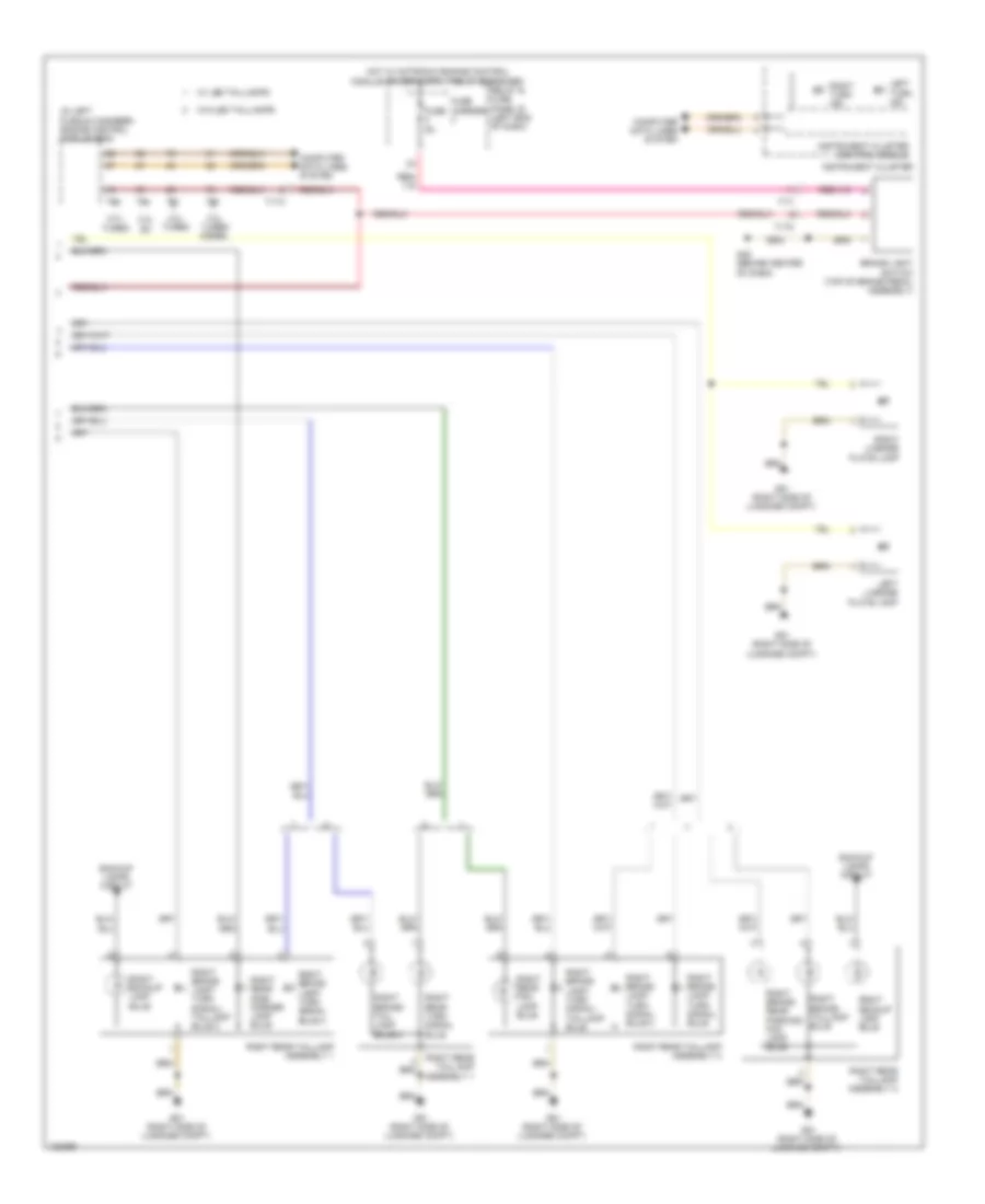
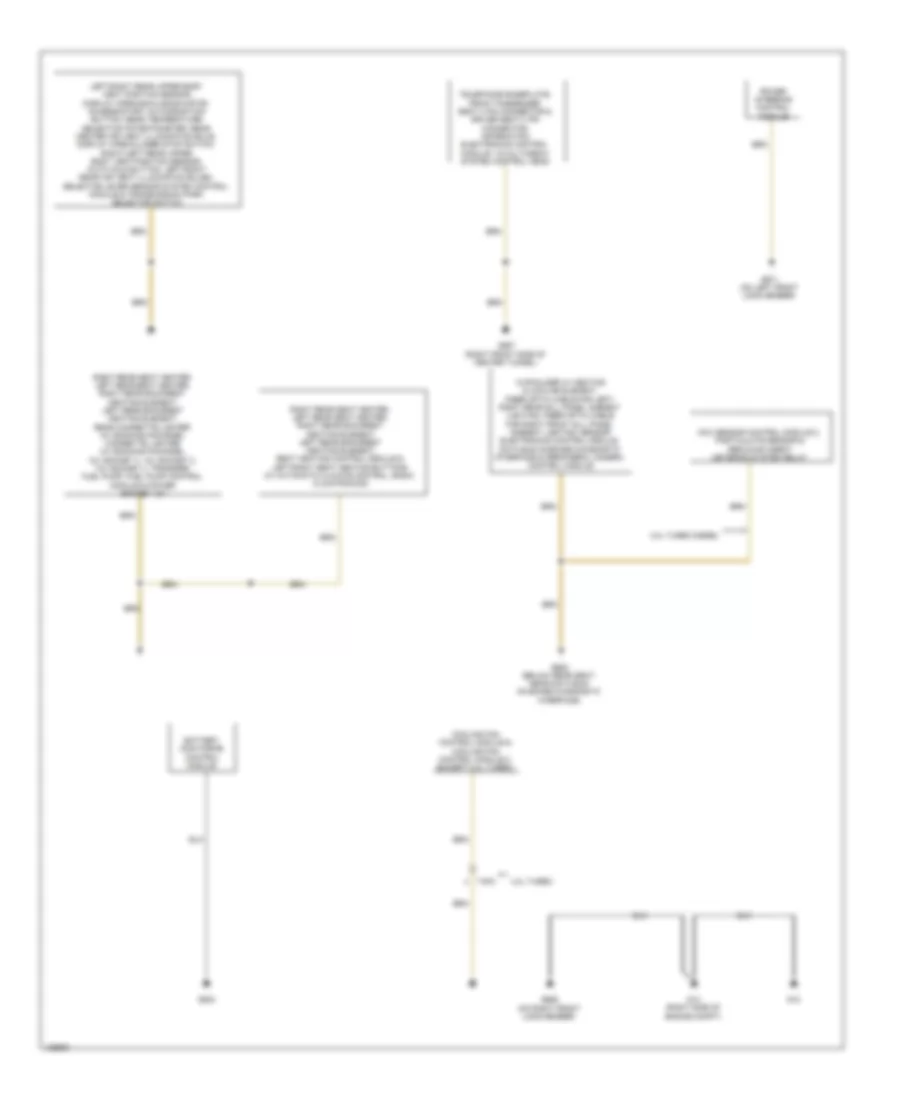
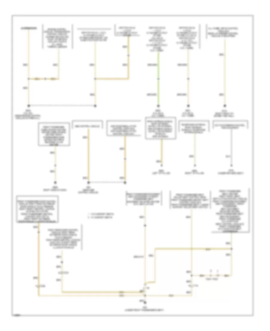
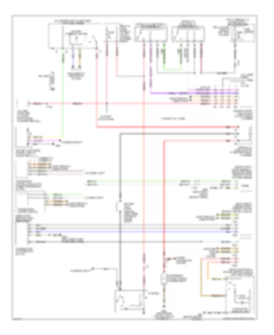
AIR CONDITIONING
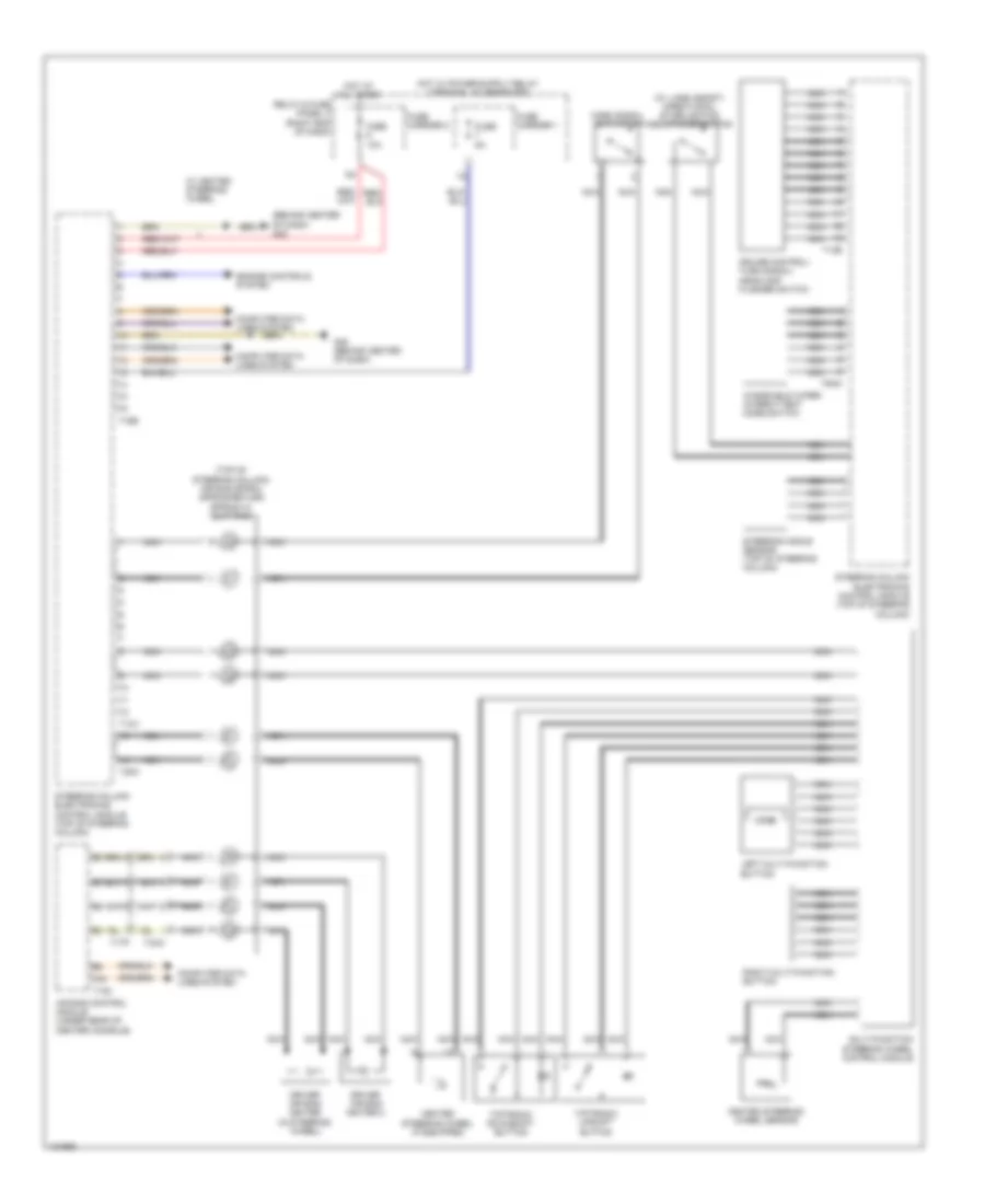
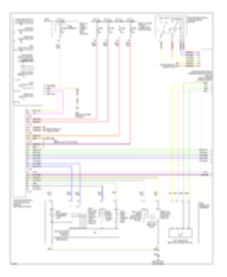
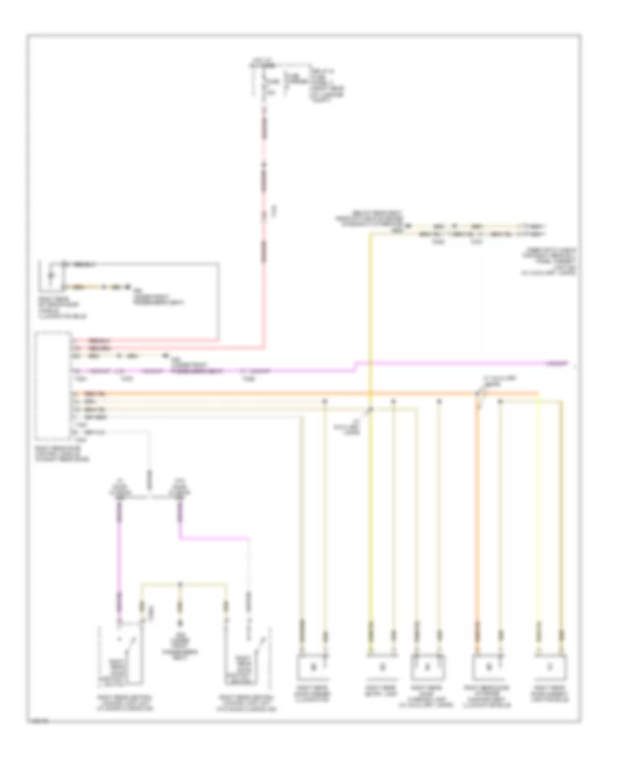
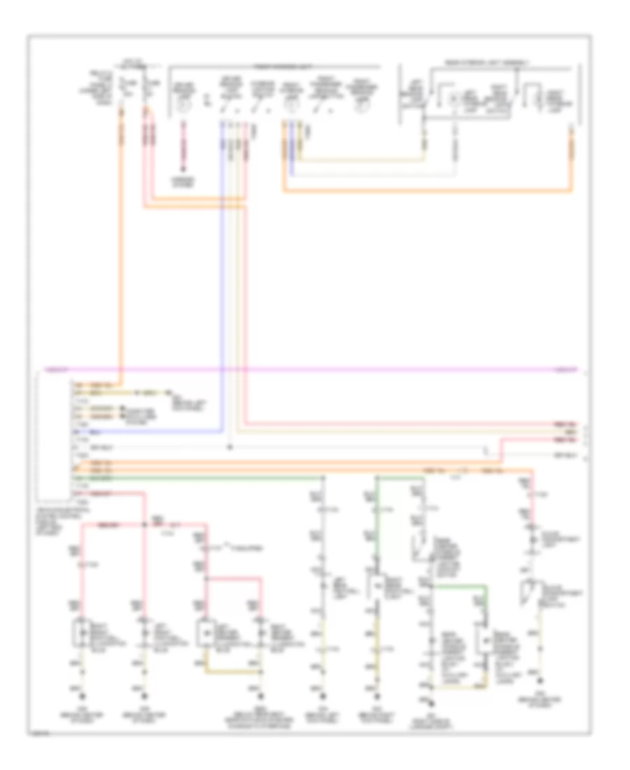
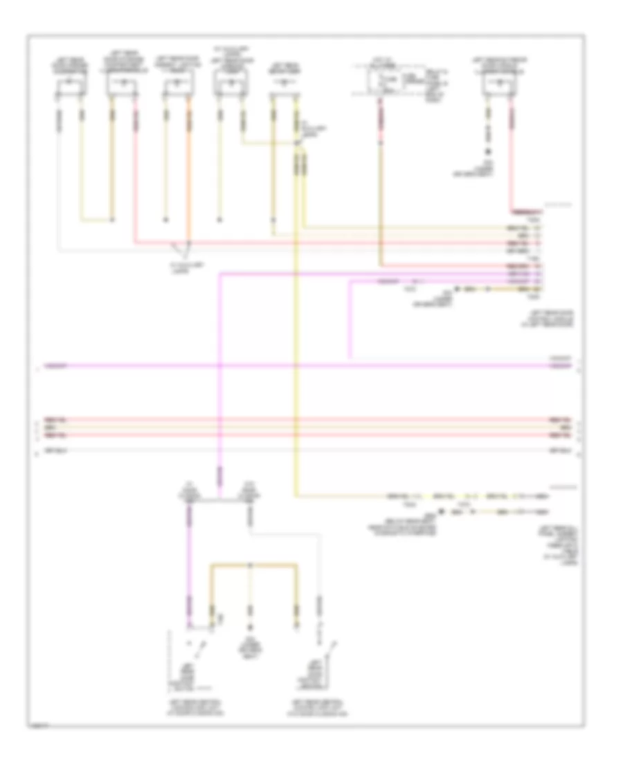
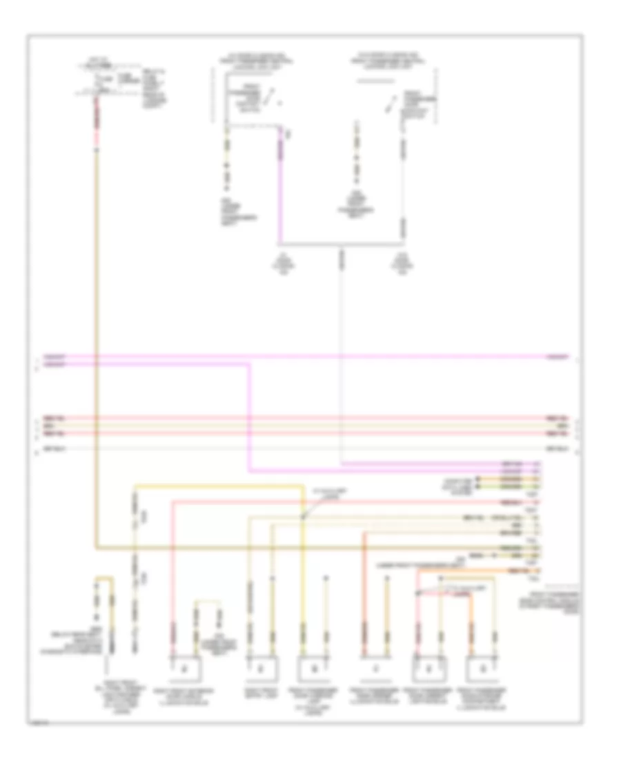
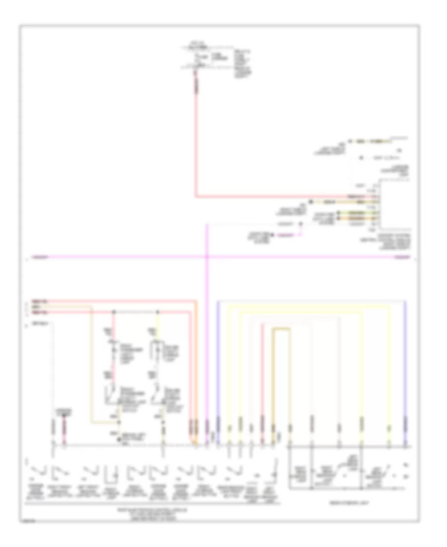
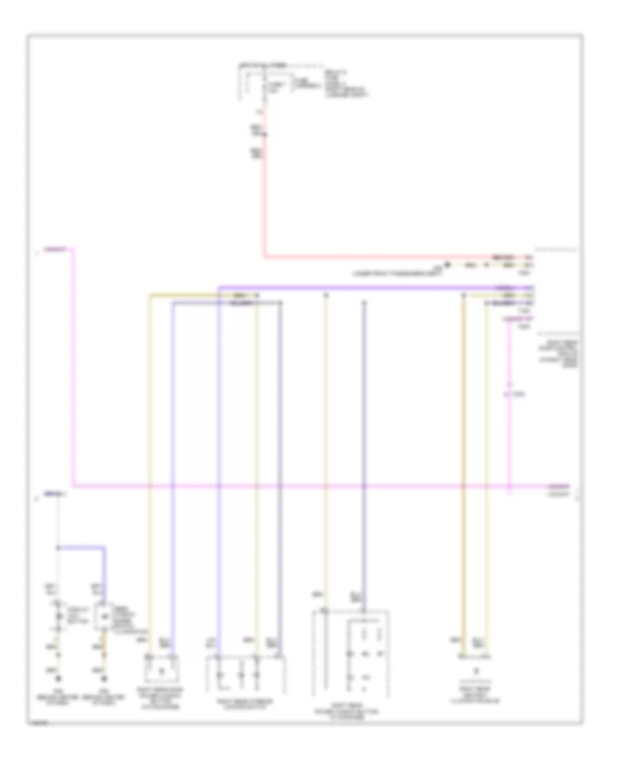
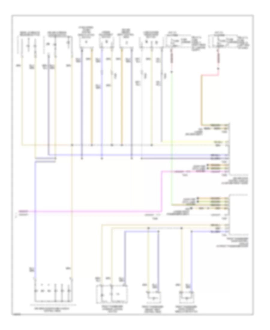
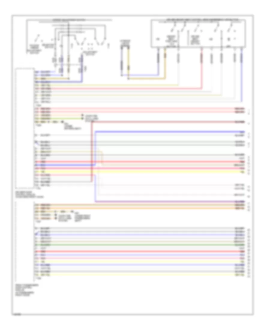
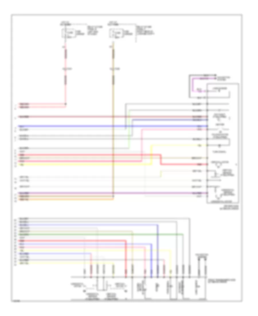
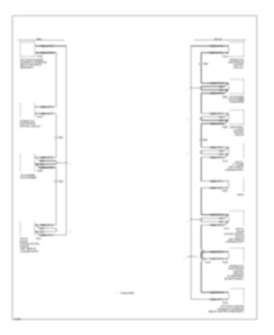
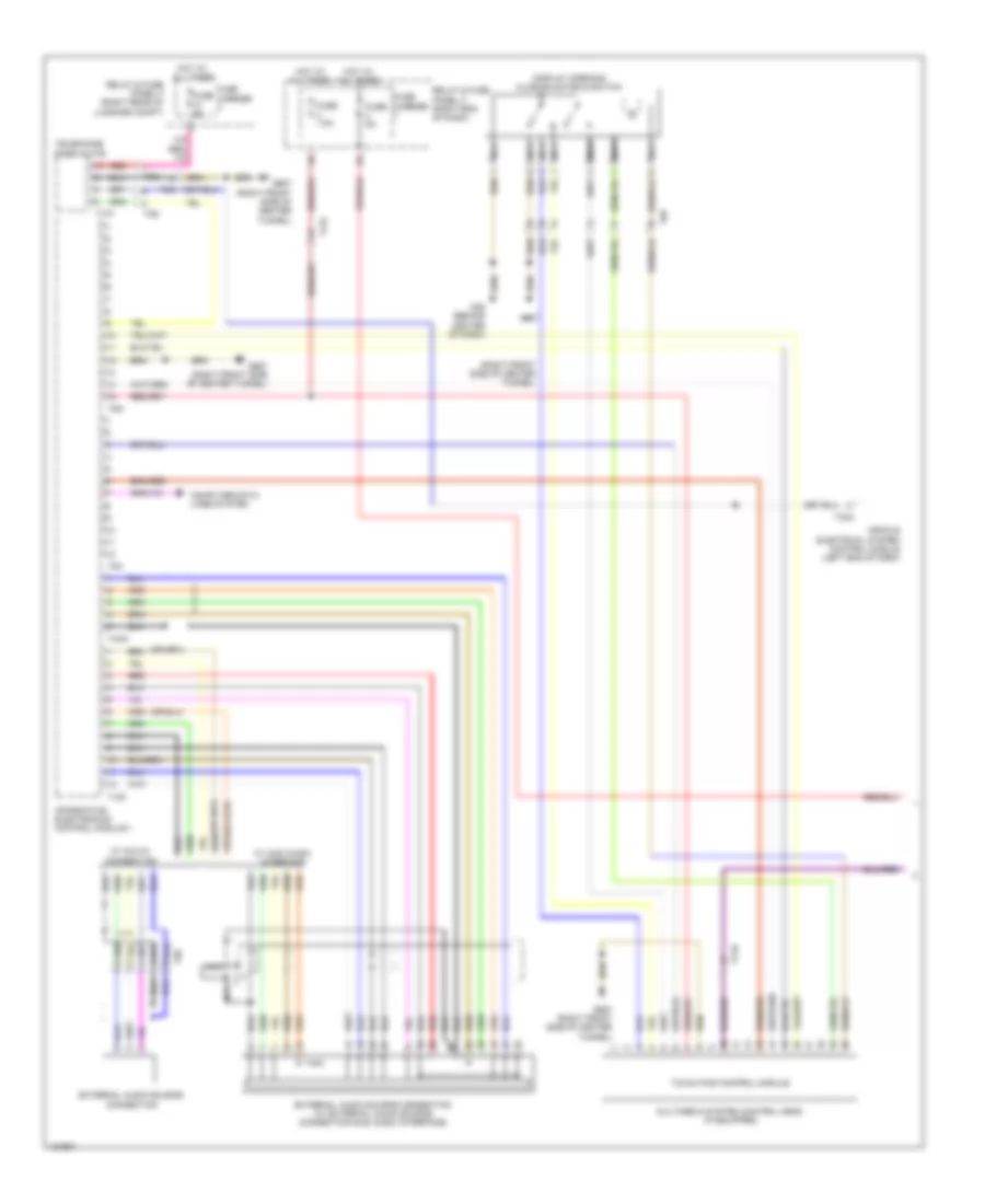
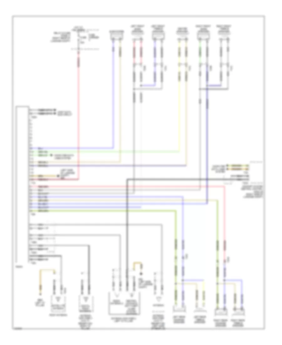
Automatic A/C Wiring Diagram, Basic (1 of 3) for Audi A6 Quattro Prestige 2014

List of elements for Automatic A/C Wiring Diagram, Basic (1 of 3) for Audi A6 Quattro Prestige 2014:
- (behind center of dash) g45
- (top center of dash) sunlight photo sensor
- A/c clutch (if equipped)
- Airflow door motor (top right front of air intake box)
- Climatronic control module
- Computer data lines system
- Coolant recirculation pump (w/o parking heater & except 2.0 turbo)
- Coolant shut-off valve (w/o parking heater)
- Defroster door motor (top left side of hvac assembly)
- Driver heated seat adjuster
- Fresh air blower
- Fresh air blower control module (behind glove compt)
- Front passenger heated seat adjuster
- Fuse 10a
- Fuse 40a
- Fuse carrier
- Hot at all times
- Instrument cluster
- Interior lights system
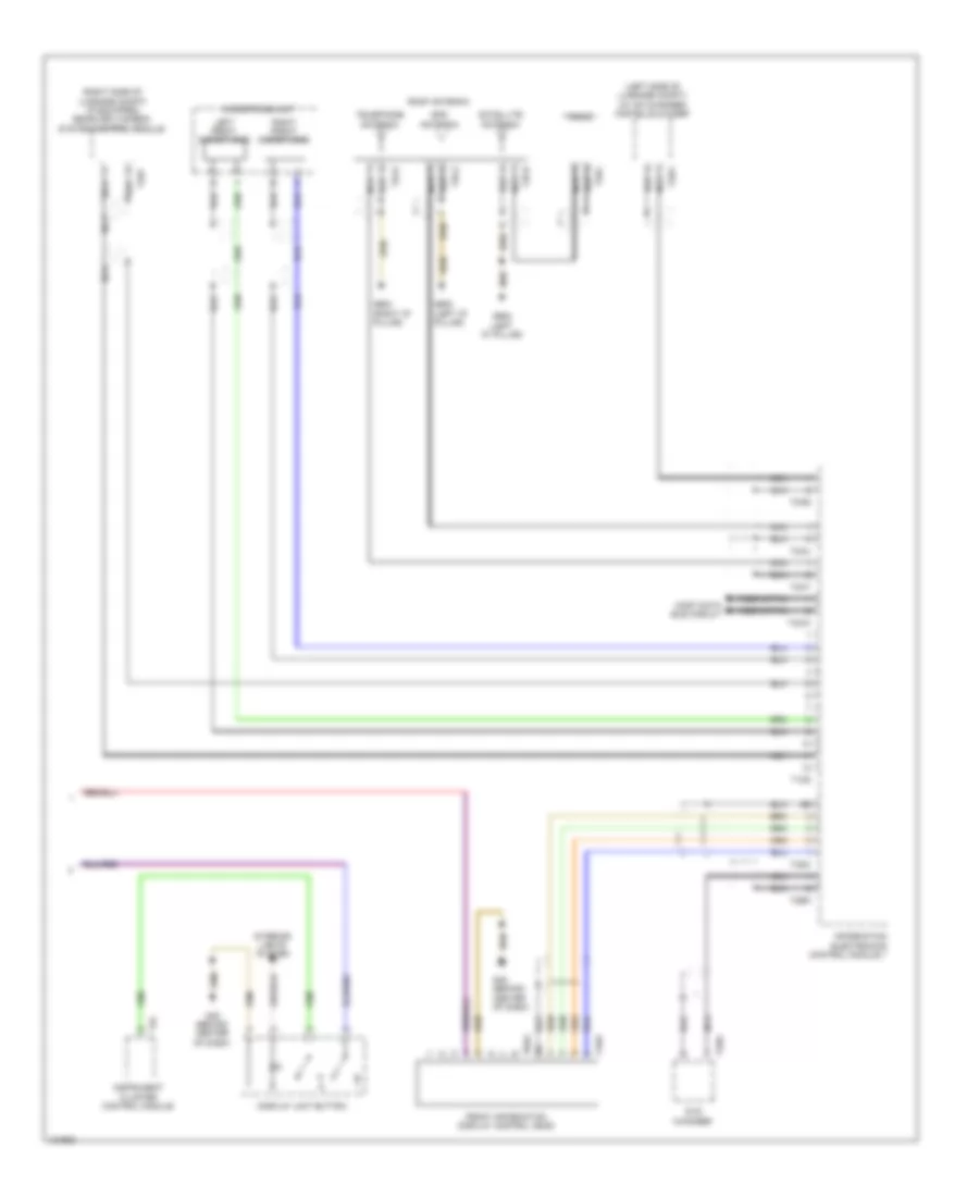
- Left center vent motor (left side of hvac unit)
- Left footwell door motor (left side of hvac unit)
- Left temperature door motor (top left side of hvac unit)
- Left vent temperature sensor (in left side vent)
- Rear temperature door motor (lower right side of hvac unit)
- Rear temperature selection potentiometer
- Recirculation door motor (top left front of air intake box)
- Relay & fuse panel c (right end of dash)
- Right center vent motor (right side of hvac unit)
- Right footwell door motor (right side of hvac unit)
- Right temperature door motor (top right side of hvac unit)
- Right vent temperature sensor (in right side vent)
- T16p
- T17i
- T17q
- T20c
- T32
- Ti7a
- Ti7h
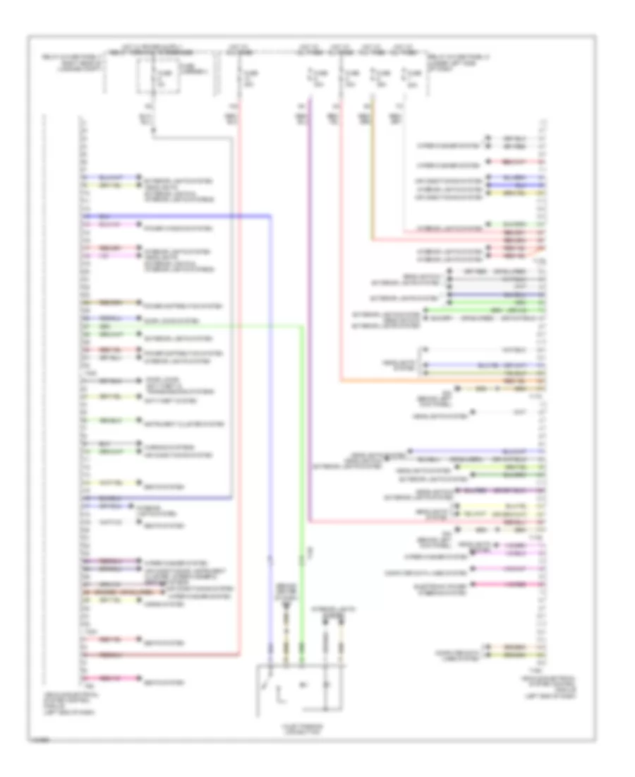
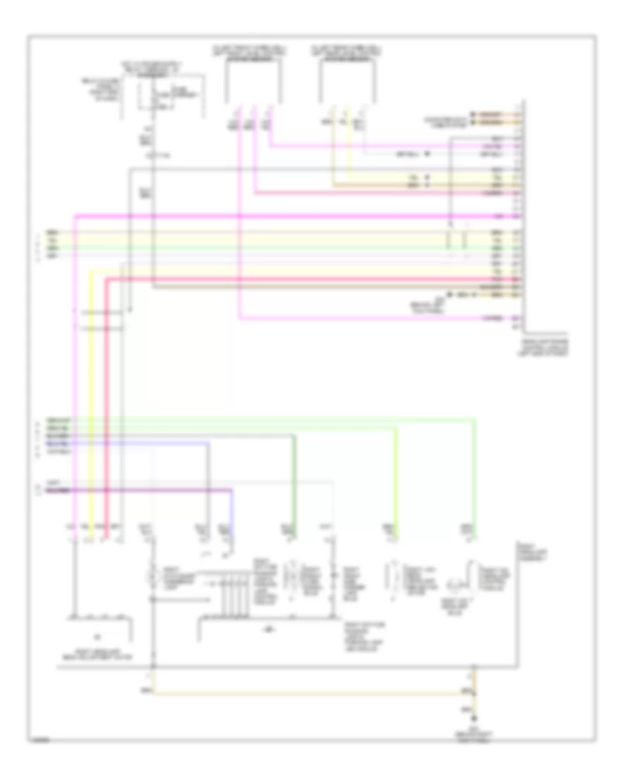
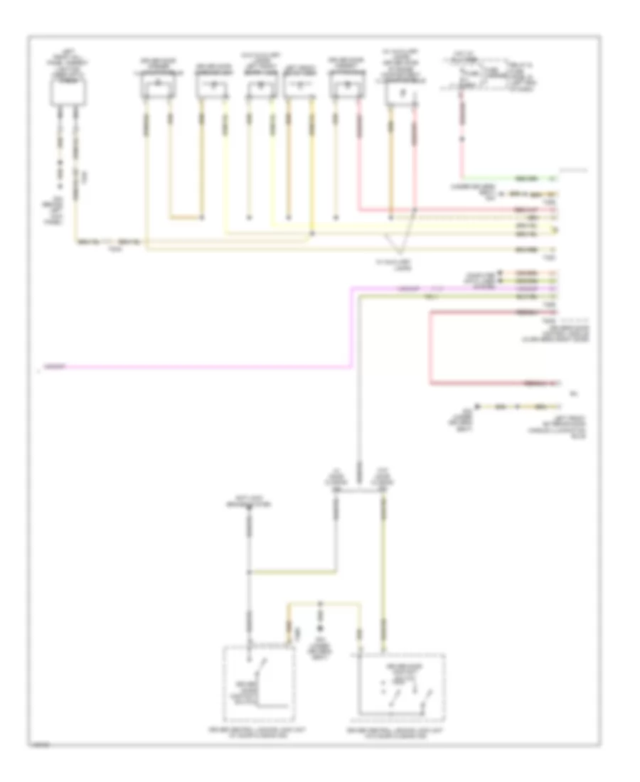
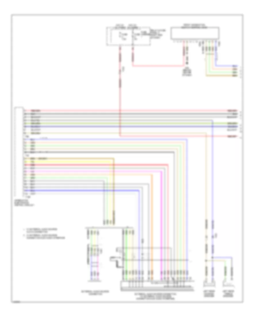
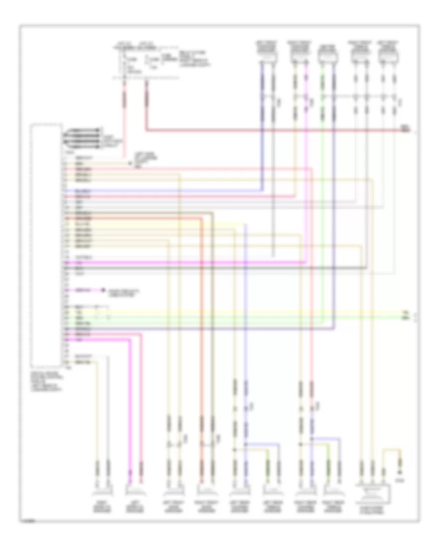
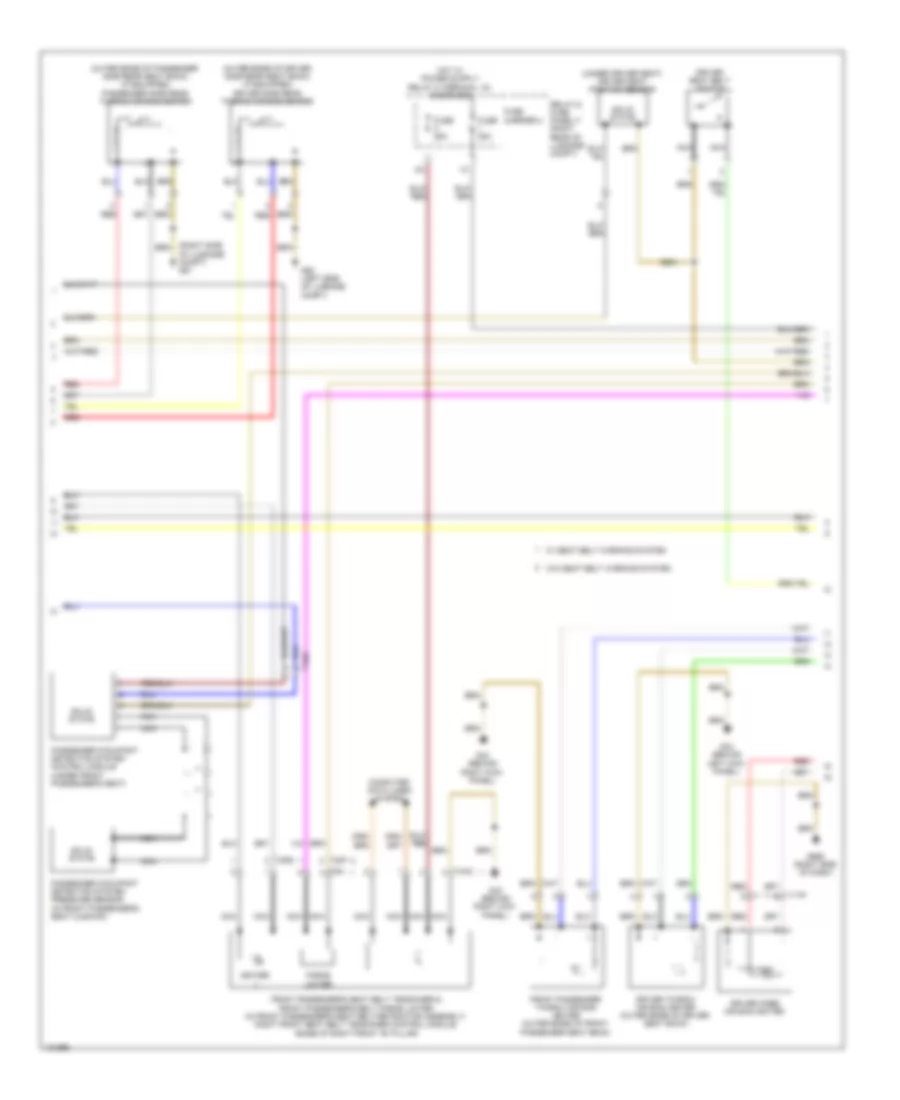
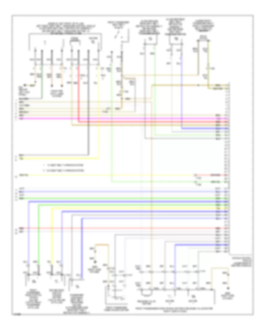
Automatic A/C Wiring Diagram, Basic (2 of 3) for Audi A6 Quattro Prestige 2014
List of elements for Automatic A/C Wiring Diagram, Basic (2 of 3) for Audi A6 Quattro Prestige 2014:
- (behind lower right side of front grille) outside air temperature sensor
- (near engine control module on firewall) g645
- (on a/c high pressure line) a/c pressure/ temperature sensor
- (on relay & fuse panel b) (3.0l turbo diesel) high heat output relay
- (on relay & fuse panel b) (3.0l turbo diesel) low heat output relay
- (or red)
- A/c compressor regulator valve (rear of compressor)
- After-run coolant pump (4.0l turbo) (left side of engine)
- Auxiliary heater heating element (3.0l turbo diesel)
- Charge air cooling pump (3.0l sc & 4.0l turbo) (in left front wheelwell)
- Computer data lines system
- Cooling circuit solenoid valve (3.0l sc)
- Engine coolant circulation pump 2 (4.0l turbo) (left rear of engine)
- Engine coolant level (ecl) sensor (in engine coolant reservoir)
- Evaporator vent temperature sensor (right side of hvac unit)
- Fuse
- Fuse 5a
- Fuse carrier
- G44 (behind left kick panel)
- G45 (behind center of dash)
- G645 (near engine control module on on firewall)
- G687 (right front side of center tunnel)
- Heating element fuse 1
- Heating element fuse 2
- Hot at all times
- Humidity sensor in fresh air intake duct
- Interior lights system
- Left footwell vent temperature sensor (lower left side of hvac unit)
- Panel)
- Rear center air vent illumination bulb
- Relay & fuse panel b (left end of dash)
- Right footwell vent temperature sensor (right side of hvac assembly)
- T16c
- T17a
- T17d
- T32a
- Vehicle electrical system control module (left end of dash)
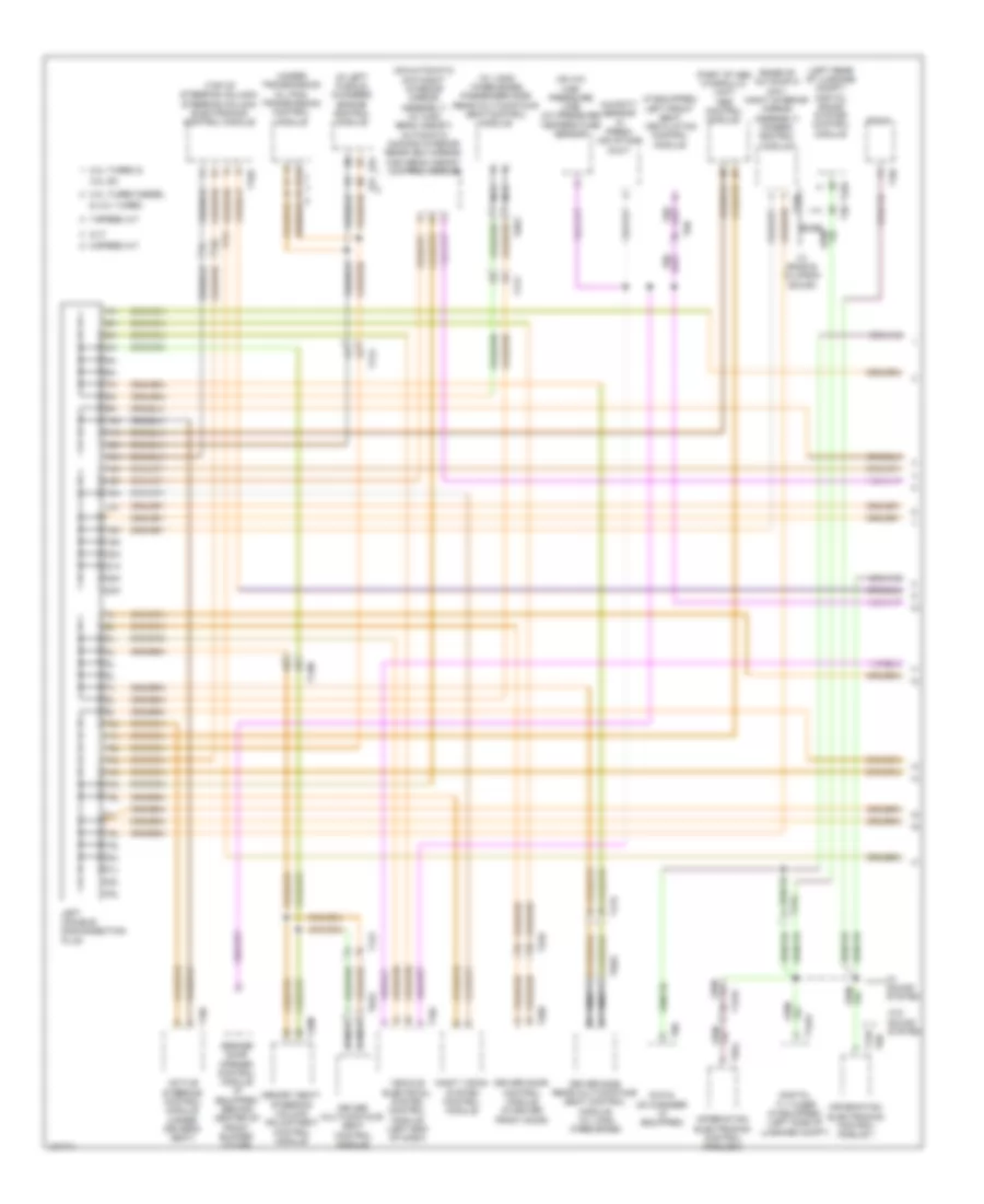
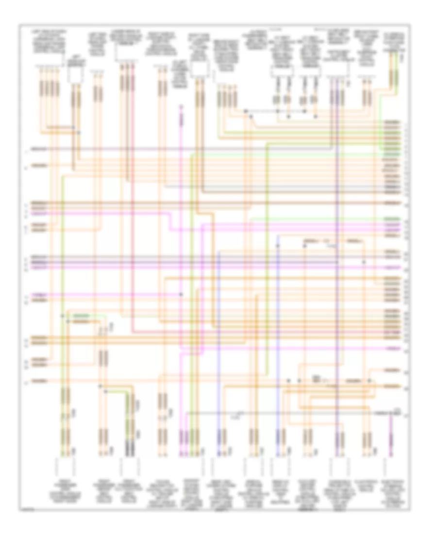
Automatic A/C Wiring Diagram, Basic (3 of 3) for Audi A6 Quattro Prestige 2014
List of elements for Automatic A/C Wiring Diagram, Basic (3 of 3) for Audi A6 Quattro Prestige 2014:
- (behind left side of radiator) (3.0l sc & 4.0l turbo) coolant fan 2
- (coolant fan 2: behind left side of radiator) (coolant fan: behind right side of radiator) coolant fan/coolant fan 2
- (or red)
- 11a
- 16a
- 2.0l turbo
- 3.0l sc
- 3.0l turbo diesel
- 4.0l turbo
- Computer data lines system
- Coolant fan
- Coolant fan 2
- Coolant fan control (fc) control module 2 (3.0l sc & 4.0l turbo) (on right coolant fan motor)
- Coolant fan control (fc) module (on left coolant fan motor)
- Coolant fan fuse 40a/ 60a/ 80a
- Coolant fan second speed fuse 40a/ 60a/ 80a
- Coolant recirculation pump (2.0l turbo)
- Engine control module (ecm) (in left plenum chamber)
- Engine coolant temperature (ect) sensor (2.0l turbo: left side of engine block) (3.0l turbo diesel: top left center of engine) (3.0l sc & 4.0l turbo: front of engine)
- Engine coolant temperature sensor on radiator outlet (3.0l turbo diesel & 4.0l turbo) (4.0l turbo: on lower left hose on radiator) (3.0l turbo diesel: on lower right hose on radiator)
- Engine temperature control sensor (front of left cylinder bank)
- Except 2.0l turbo
- Fuse 15a
- Fuse 5a
- G645 (near engine control module on on firewall)
- G685 (on right front long member)
- Hot at all times
- Nca
- Red
- Relay & fuse panel a (in left plenum chamber e-box)
- T105
- T14a
- T14b
- T17b
- T17g
- T4fm
- T4fn
- T60
- T91
- T94
- Terminal 30 wire junction (in center plenum chamber)
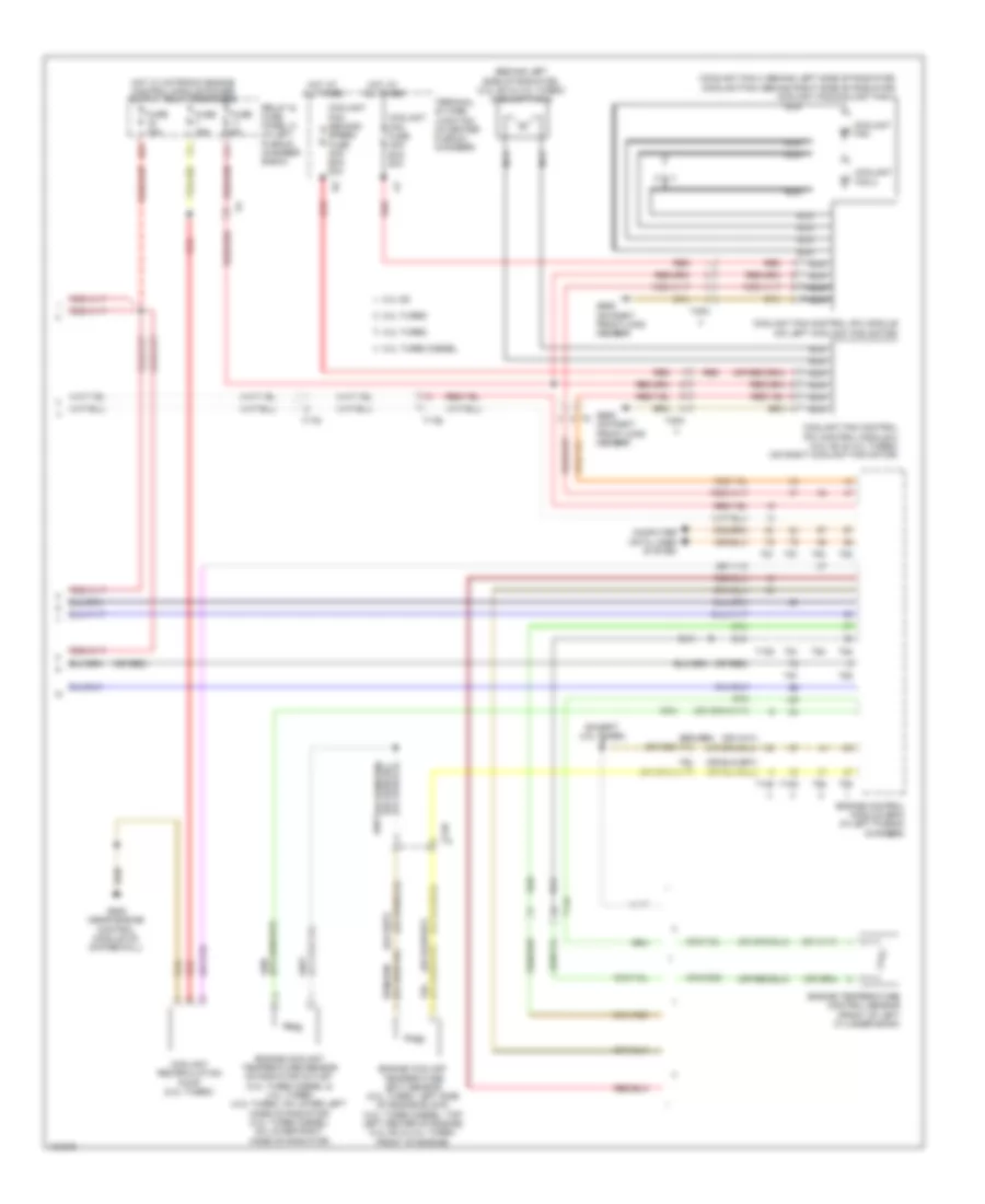
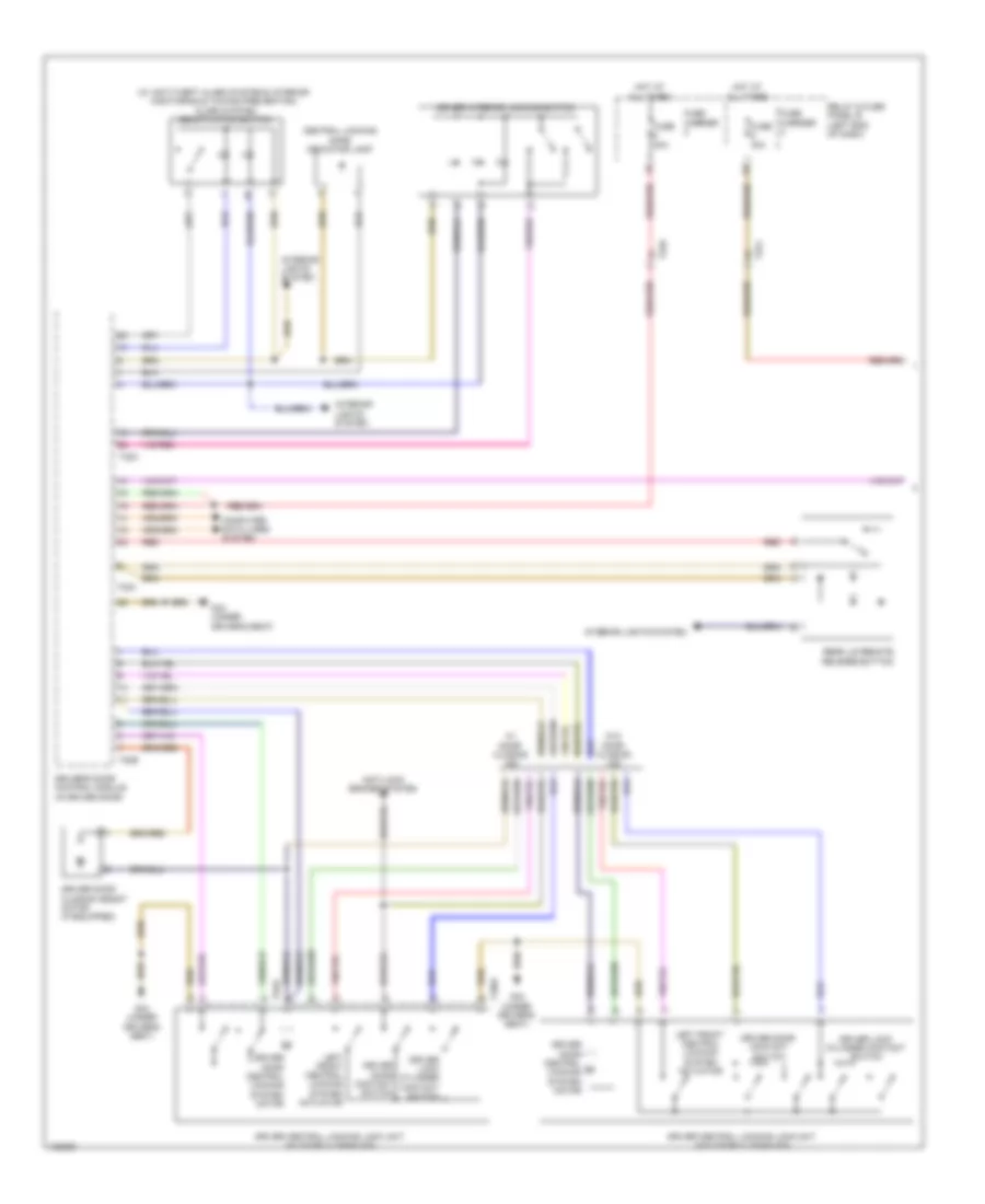
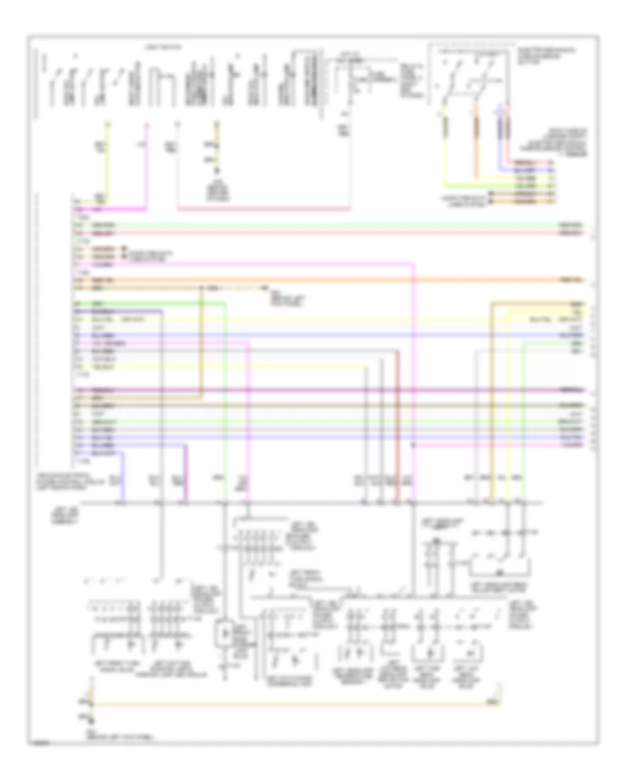
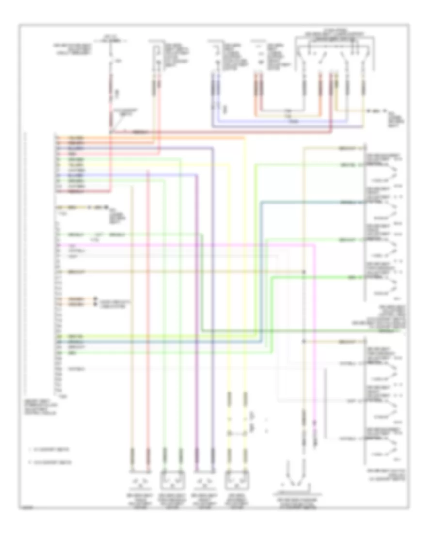
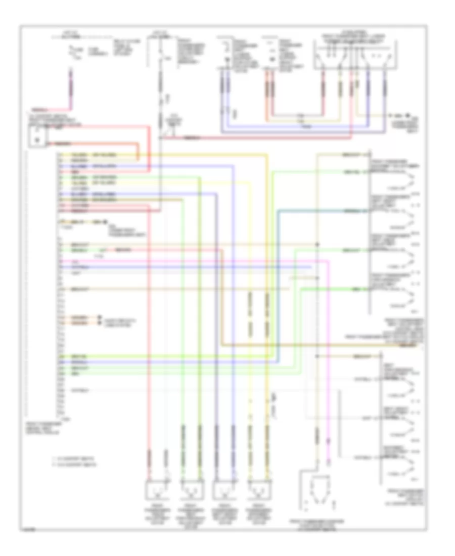
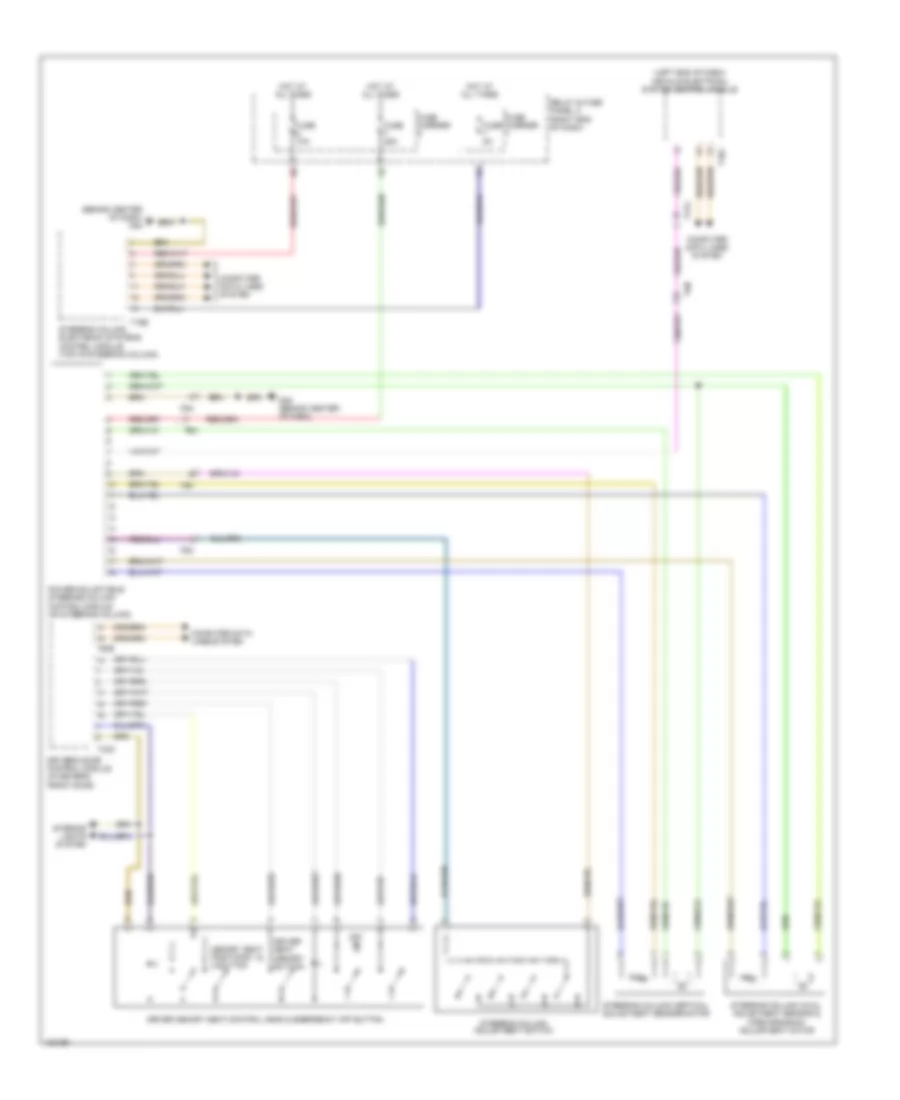
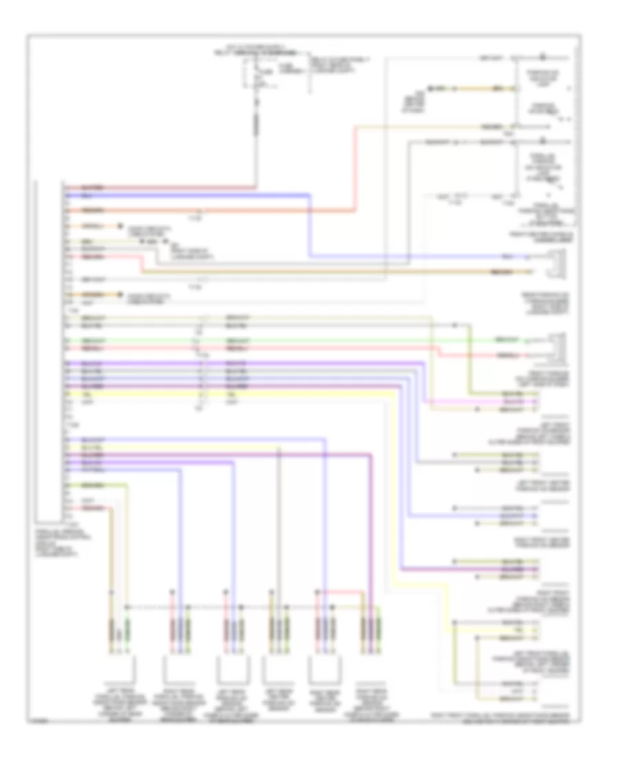
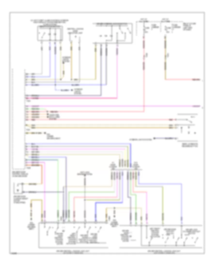
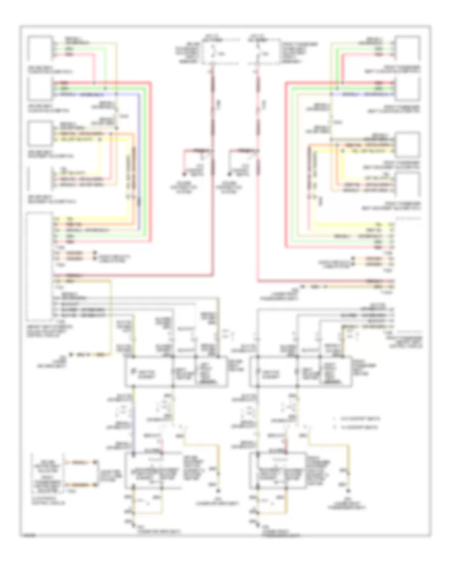
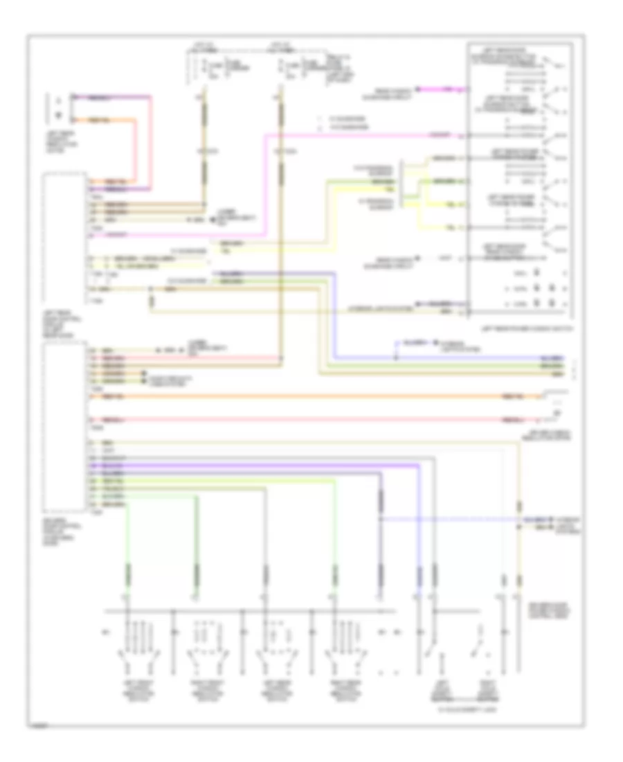
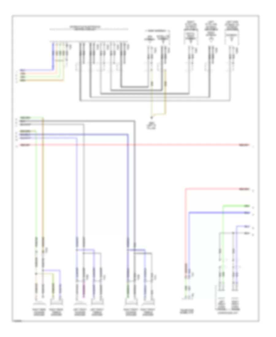
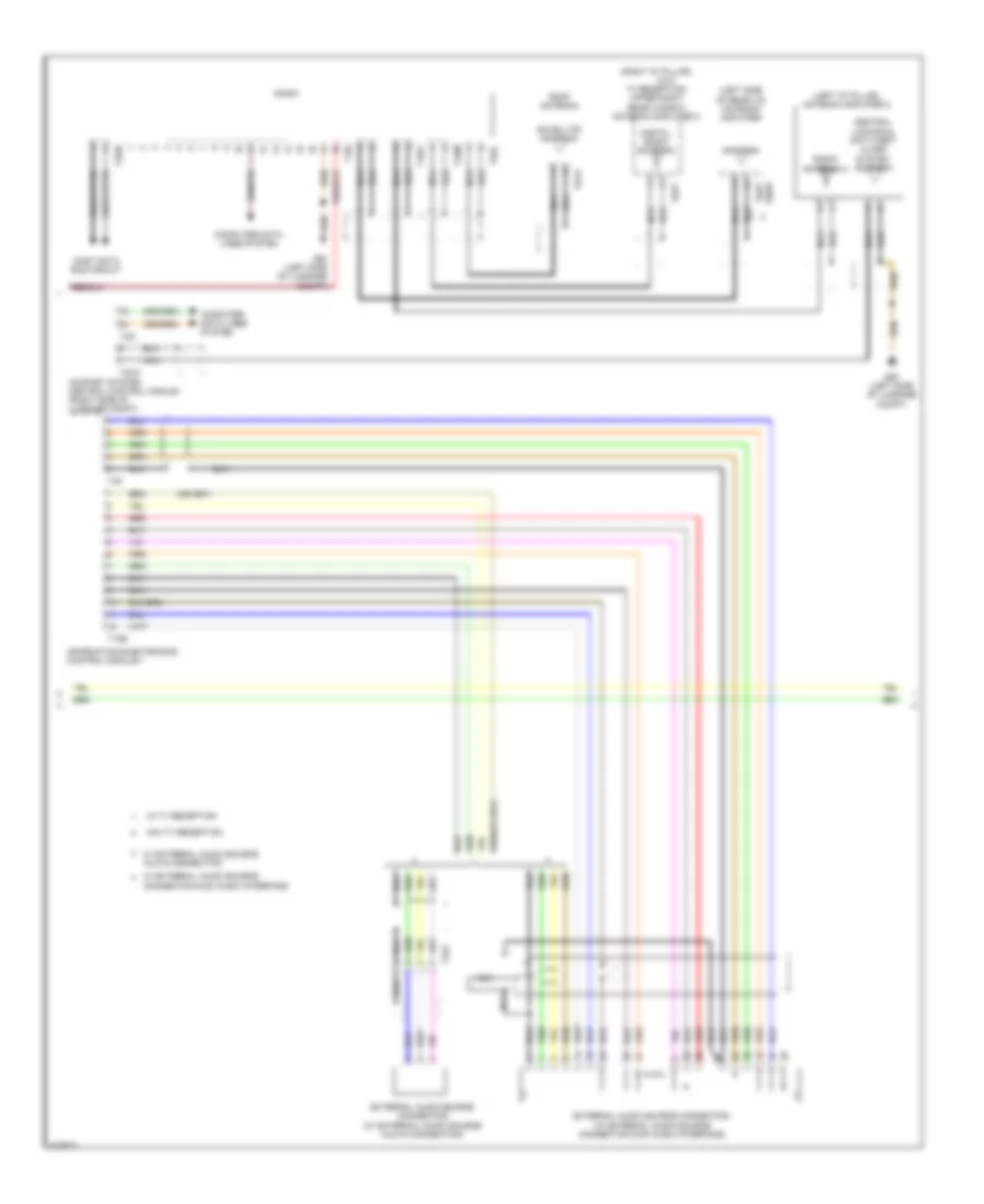
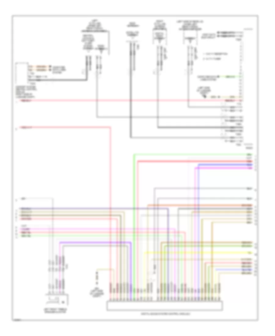
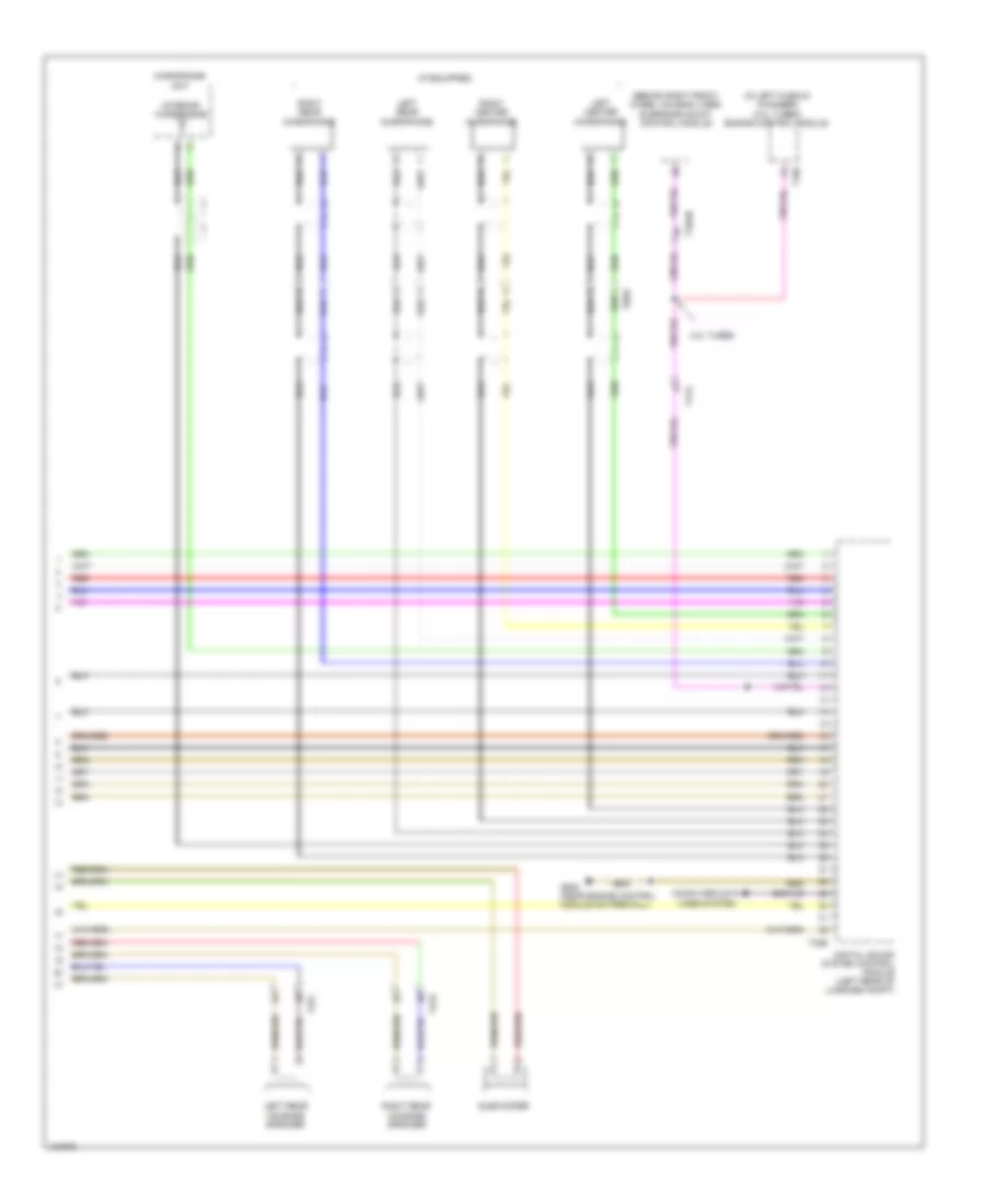
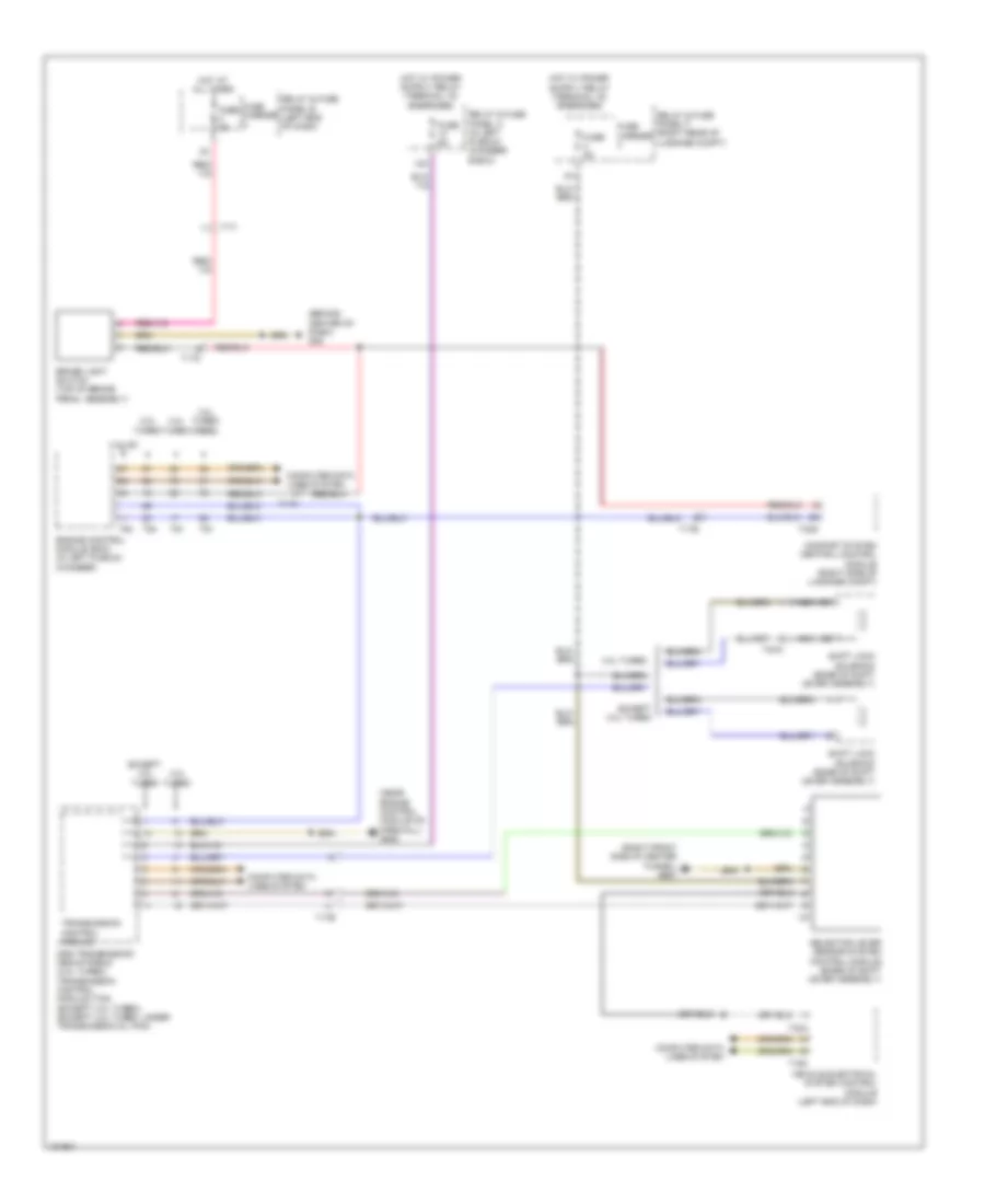
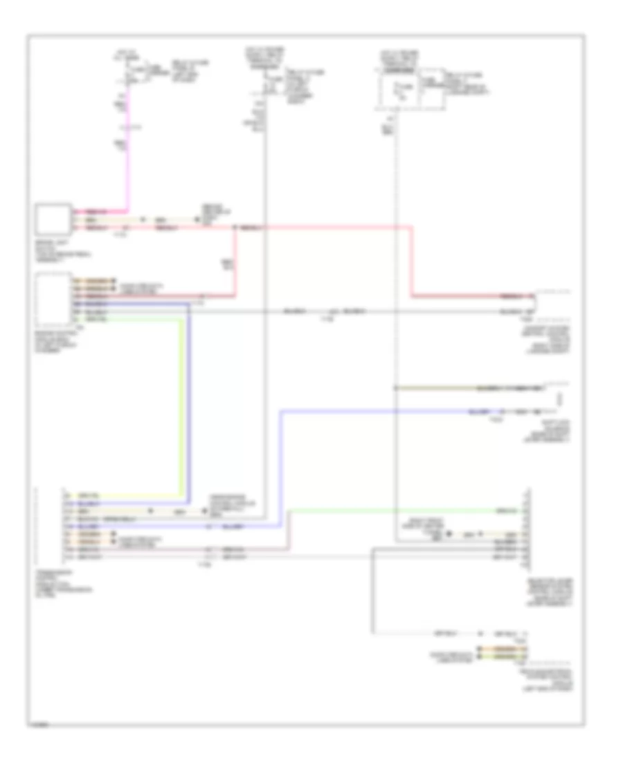
Automatic A/C Wiring Diagram, Comfort (1 of 4) for Audi A6 Quattro Prestige 2014
List of elements for Automatic A/C Wiring Diagram, Comfort (1 of 4) for Audi A6 Quattro Prestige 2014:
- (behind center of dash) g45
- (except 2.0l turbo & w/o parking heater) coolant recirculation pump
- (w/o parking heater)
- A/c clutch (if equipped)
- Climatronic control module
- Computer data lines system
- Coolant shut-off valve
- Defroster door motor (top left side of hvac assembly)
- Driver heated seat adjuster
- Evaporator vent temperature sensor (right side of hvac unit)
- Front passenger heated seat adjuster
- Fuse 10a
- Fuse 40a
- Fuse carrier
- Hot at all times
- Left center vent motor (left side of hvac unit)
- Left footwell door motor (left side of hvac unit)
- Left footwell vent temperature sensor (lower left side of hvac unit)
- Left rear air door motor (lower left side of hvac assembly)
- Left rear temperature door motor (lower left side of hvac assembly)
- Left side vent motor (left side of hvac unit)
- Left temperature door motor (top left side of hvac unit)
- Relay & fuse panel c (right end of dash)
- Right footwell door motor (right side of hvac unit)
- Right footwell vent temperature sensor (right side of hvac assembly)
- Right rear air door motor (lower right side of hvac unit)
- Right rear temperature door motor (lower right side of hvac unit)
- Sunlight photo sensor (top center of dash)
- T16p
- T17i
- T20c
- Ti7a
- Ti7h
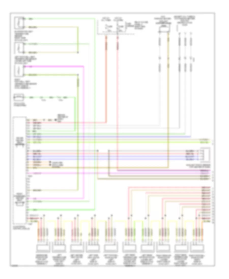
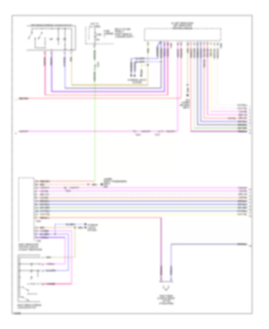
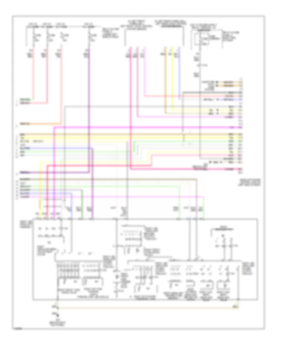
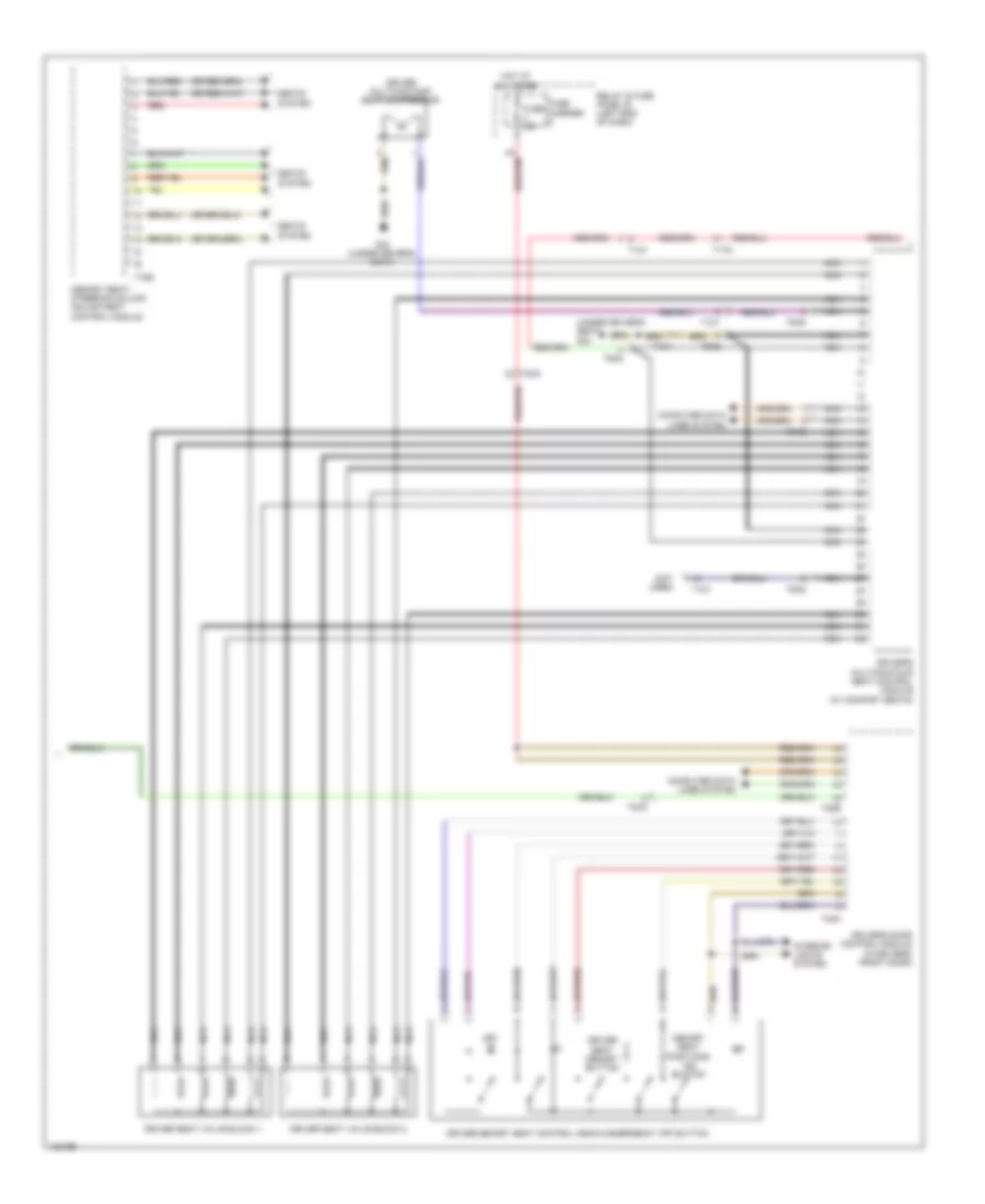
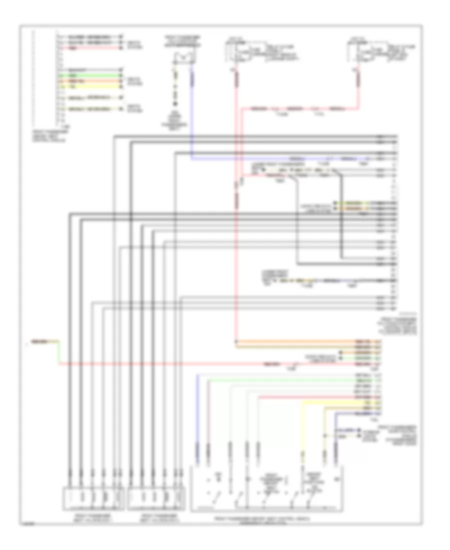
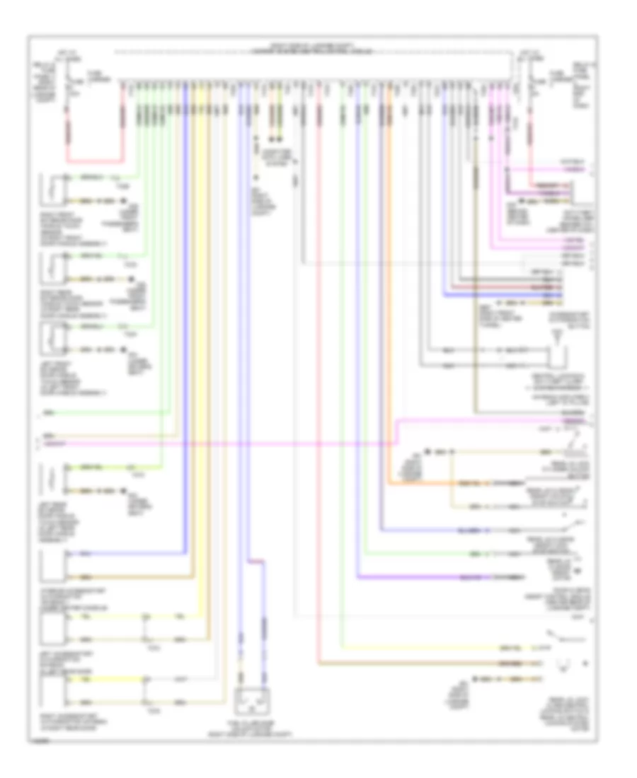
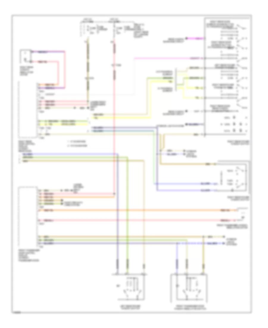
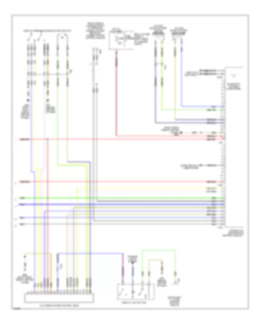
Automatic A/C Wiring Diagram, Comfort (2 of 4) for Audi A6 Quattro Prestige 2014
List of elements for Automatic A/C Wiring Diagram, Comfort (2 of 4) for Audi A6 Quattro Prestige 2014:
- (air quality sensor: under right plenum chamber cover) air quality sensor/ humidity sensor in fresh air intake duct
- (in engine coolant reservoir) engine coolant level (ecl) sensor
- A/c compressor regulator valve (rear of compressor)
- A/c pressure/ temperature sensor (on a/c high pressure line)
- Airflow door motor (top right front of air intake box)
- Computer data lines system
- Fresh air blower control module (behind glove compt)
- Fuse 5a
- Fuse carrier
- G44 (behind left kick panel)
- G45 (behind center of dash)
- Indirect ventilation door motor (right side of hvac assembly)
- Instrument cluster
- Interior lights system
- Left vent temperature sensor (in left side vent)
- Outside air temperature sensor (behind lower right side of front grille)
- Recirculation door motor (top left front of air intake box)
- Relay & fuse panel b (left end of dash)
- Right center vent motor (right side of hvac unit)
- Right side vent motor (right side of hvac unit)
- Right temperature door motor (top right side of hvac unit)
- Right vent temperature sensor (in right side vent)
- T16c
- T17a
- T17d
- T32
- T32a
- T32c
- Vehicle electrical system control module (left end of dash)
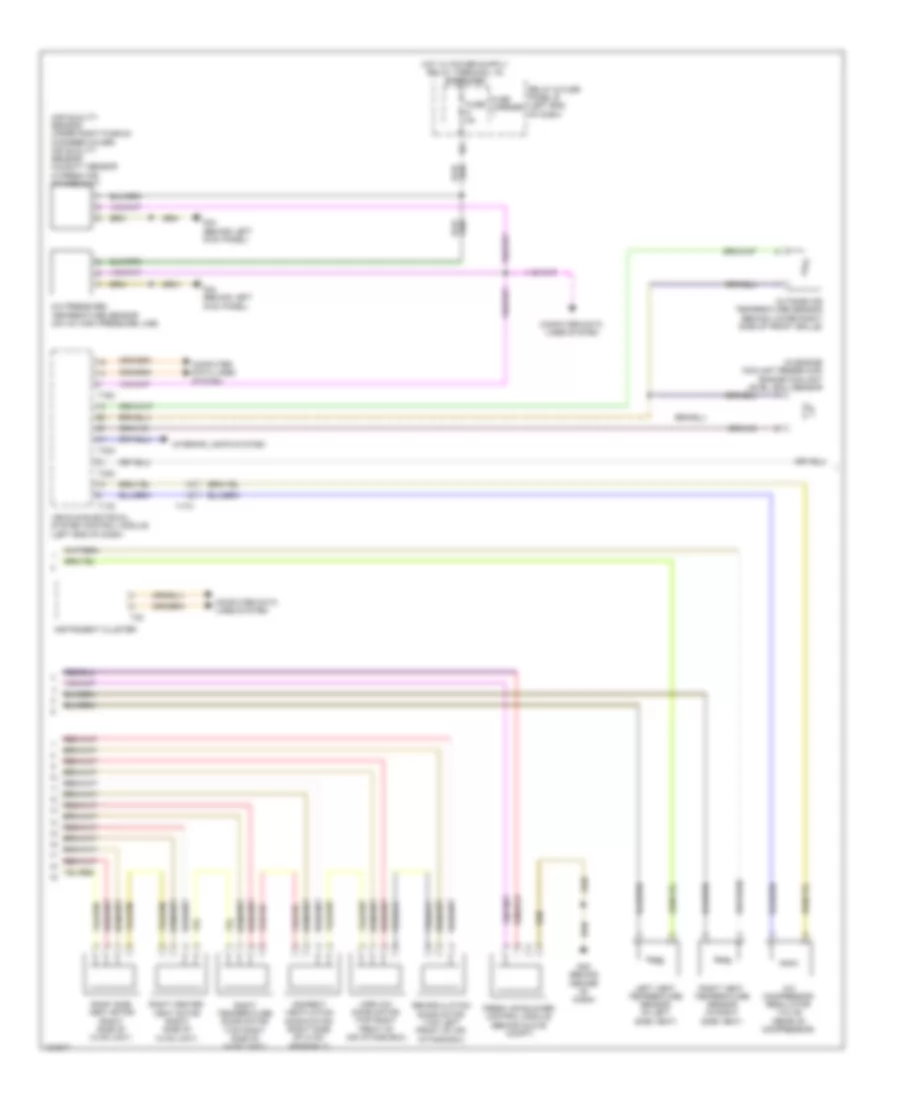
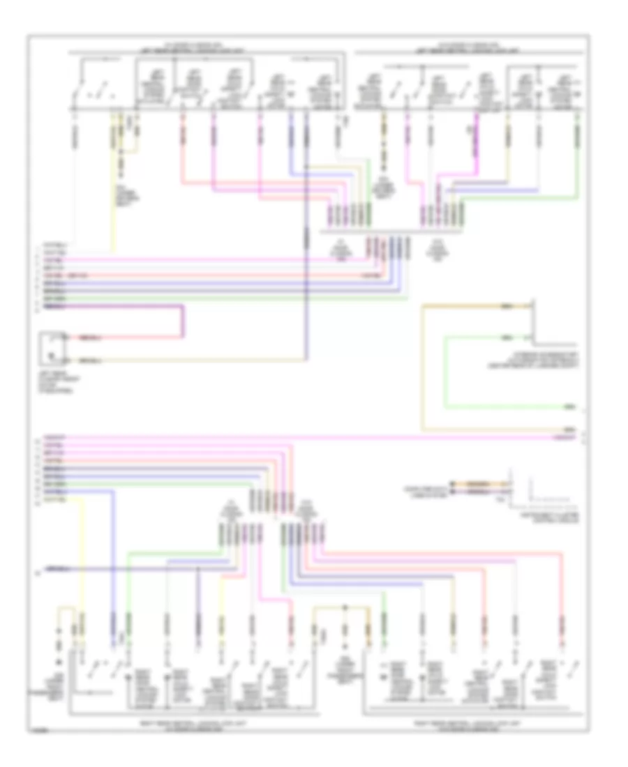
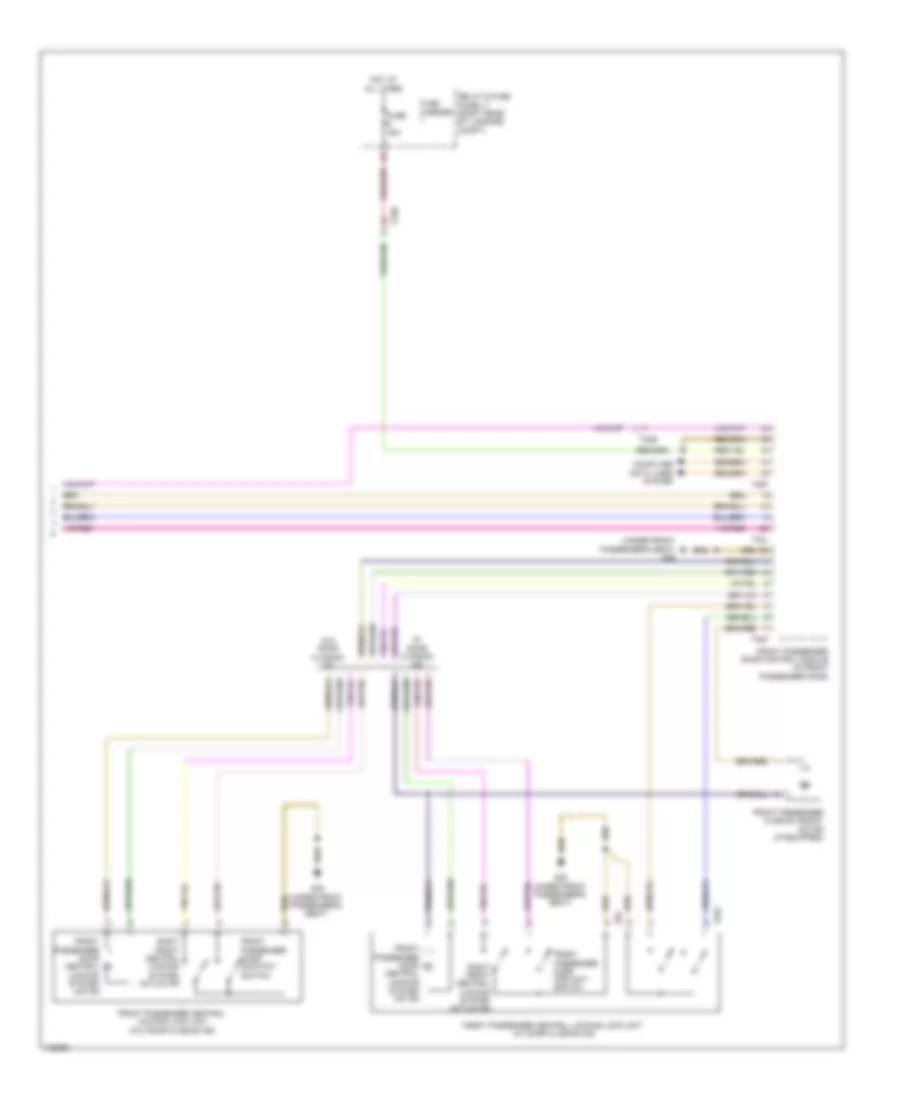
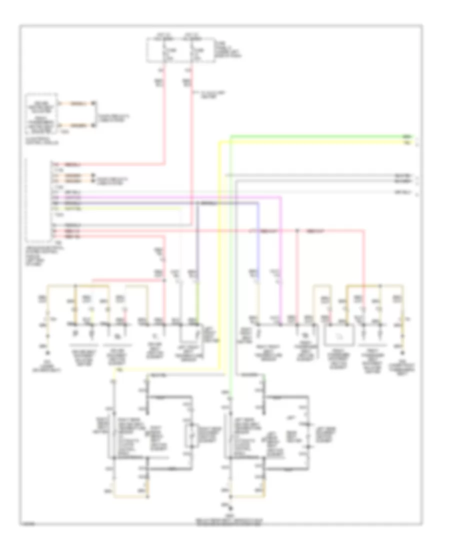
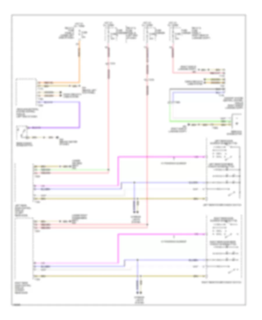
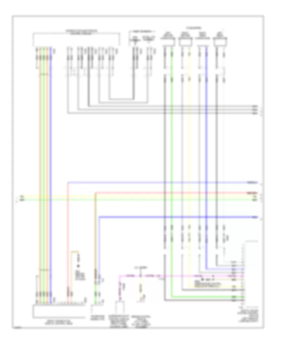
Automatic A/C Wiring Diagram, Comfort (3 of 4) for Audi A6 Quattro Prestige 2014
List of elements for Automatic A/C Wiring Diagram, Comfort (3 of 4) for Audi A6 Quattro Prestige 2014:
- (behind center of dash) g45
- (near engine control module on firewall) g645
- (on relay & fuse panel b) (3.0l turbo diesel) high heat output relay
- (on relay & fuse panel b) (3.0l turbo diesel) low heat output relay
- (or red)
- After-run coolant pump (4.0l turbo) (left side of engine)
- Auxiliary heater heating element (3.0l turbo diesel)
- Center instrument panel vent illumination bulb
- Charge air cooling pump (4.0l turbo & 3.0l sc) (in left front wheelwell)
- Climatronic control module
- Cooling circuit solenoid valve (3.0l sc)
- Engine coolant circulation pump 2 (4.0l turbo) (left rear of engine)
- Fuse
- G45 (behind center of dash)
- G645 (near engine control module on firewall)
- Heating element fuse 1
- Heating element fuse 2
- Hot at all times
- Left instrument panel vent illumination bulb
- Left side vent position sensor (in left side vent)
- Right instrument panel vent illumination bulb
- Right side vent position sensor (in right side vent)
- Right/left center vent position sensor (in right/left center vent)
- T16f
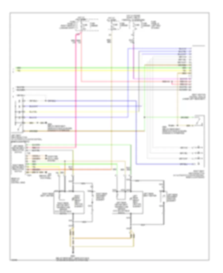
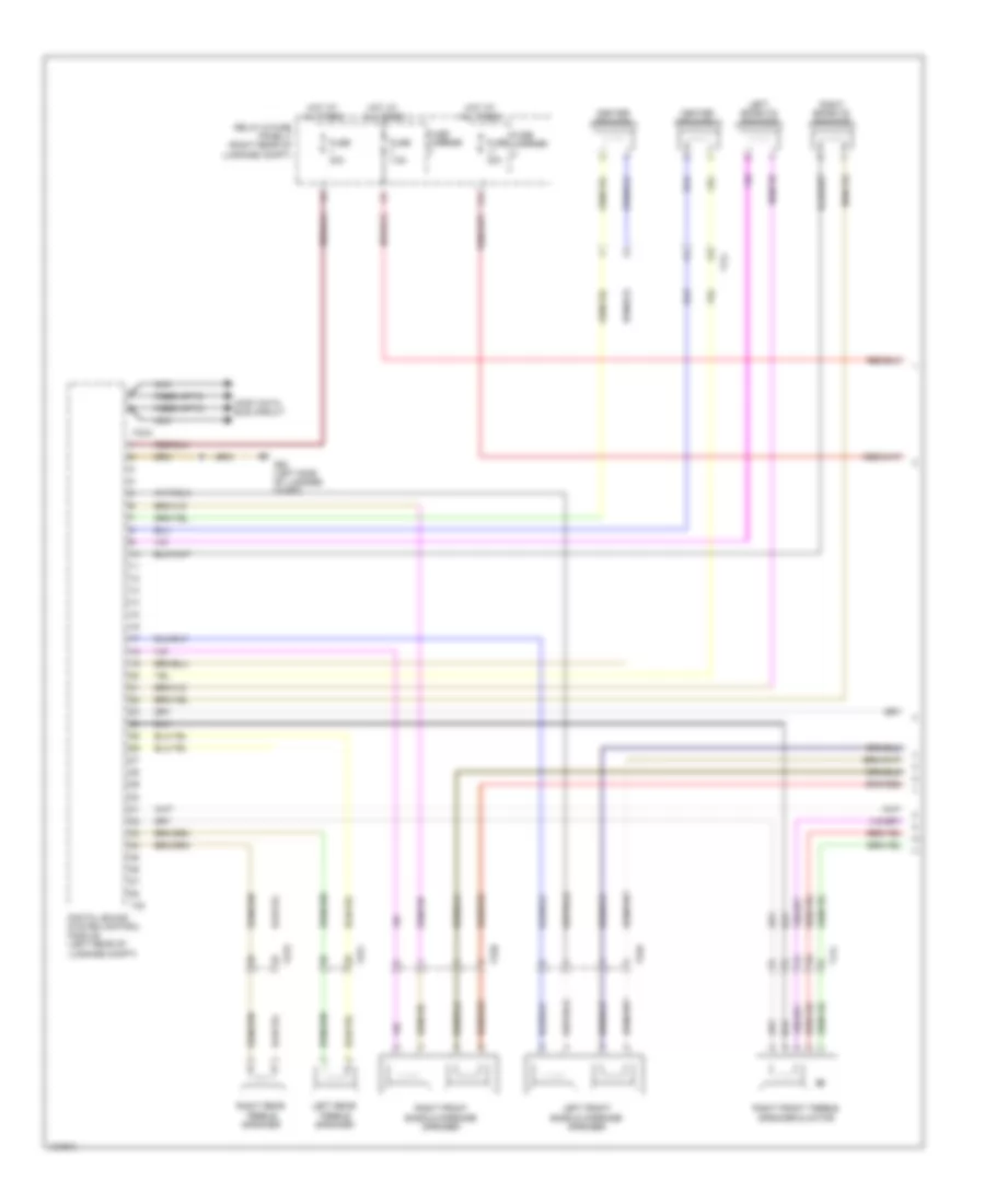
Automatic A/C Wiring Diagram, Comfort (4 of 4) for Audi A6 Quattro Prestige 2014
List of elements for Automatic A/C Wiring Diagram, Comfort (4 of 4) for Audi A6 Quattro Prestige 2014:
- (behind left side of radiator) (3.0l sc & 4.0l turbo) coolant fan 2
- (coolant fan 2: behind left side of radiator) (coolant fan: behind right side of radiator) coolant fan/coolant fan 2
- (or red)
- 11a
- 16a
- 2.0l turbo
- 3.0l sc
- 3.0l turbo diesel
- 4.0l turbo
- Computer data lines system
- Coolant fan
- Coolant fan 2
- Coolant fan control (fc) control module 2 (3.0l sc & 4.0l turbo) (on right coolant fan motor)
- Coolant fan control (fc) module (on left coolant fan motor)
- Coolant fan fuse 40a/ 60a/ 80a
- Coolant fan second speed fuse 40a/ 60a/ 80a
- Coolant recirculation pump (2.0l turbo)
- Engine control module (ecm) (in left plenum chamber)
- Engine coolant temperature (ect) sensor (2.0l turbo: left side of engine block) (3.0l turbo diesel: top left center of engine) (3.0l sc & 4.0l turbo: front of engine)
- Engine coolant temperature sensor on radiator outlet (3.0l turbo diesel & 4.0l turbo) (4.0l turbo: on lower left hose on radiator) (3.0l turbo diesel: on lower right hose on radiator)
- Engine temperature control sensor (front of left cylinder bank)
- Except 2.0l turbo
- Fuse 15a
- Fuse 5a
- G645 (near engine control module on on firewall)
- G685 (on right front long member)
- Hot at all times
- Nca
- Red
- Relay & fuse panel a (in left plenum chamber e-box)
- T105
- T14a
- T14b
- T17b
- T17g
- T4fm
- T4fn
- T60
- T91
- T94
- Terminal 30 wire junction (in center plenum chamber)
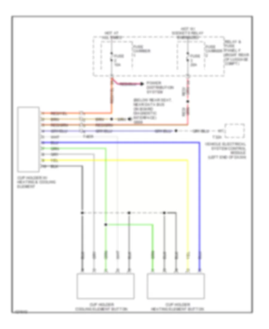
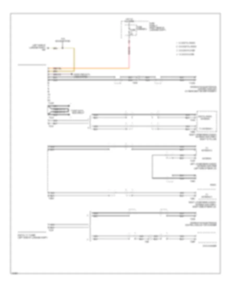
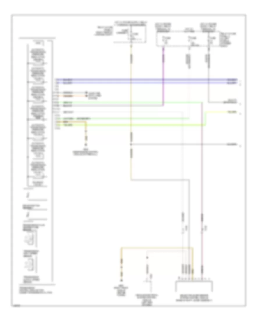
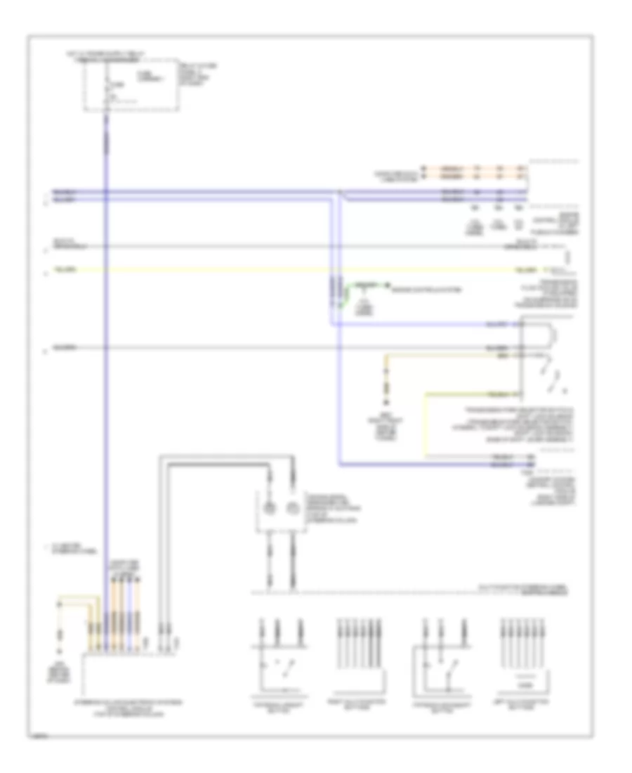
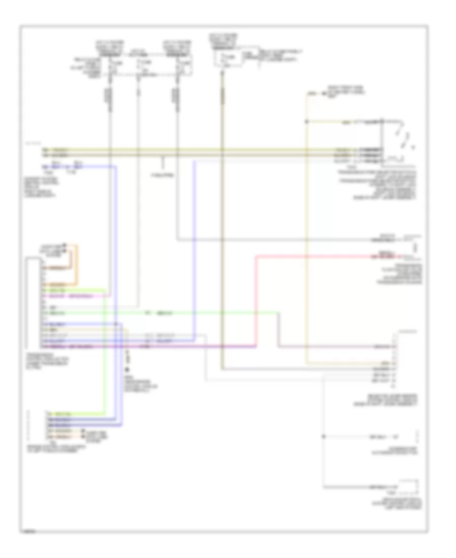
Heated And Cooled Cup Holder Wiring Diagram for Audi A6 Quattro Prestige 2014
List of elements for Heated And Cooled Cup Holder Wiring Diagram for Audi A6 Quattro Prestige 2014:
- (below rear seat, near data bus on board diagnostic interface) g688
- Cup holder cooling element button
- Cup holder heating element button
- Cup holder w/ heating & cooling element
- Fuse 10a
- Fuse 20a
- Fuse carrier
- Hot at all times
- Hot w/ sockets relay energized
- Power distribution system
- Relay & fuse panel f (right rear of luggage compt)
- T32a
- T4er
- Vehicle electrical system control module (left end of dash)
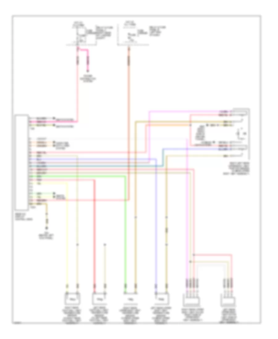
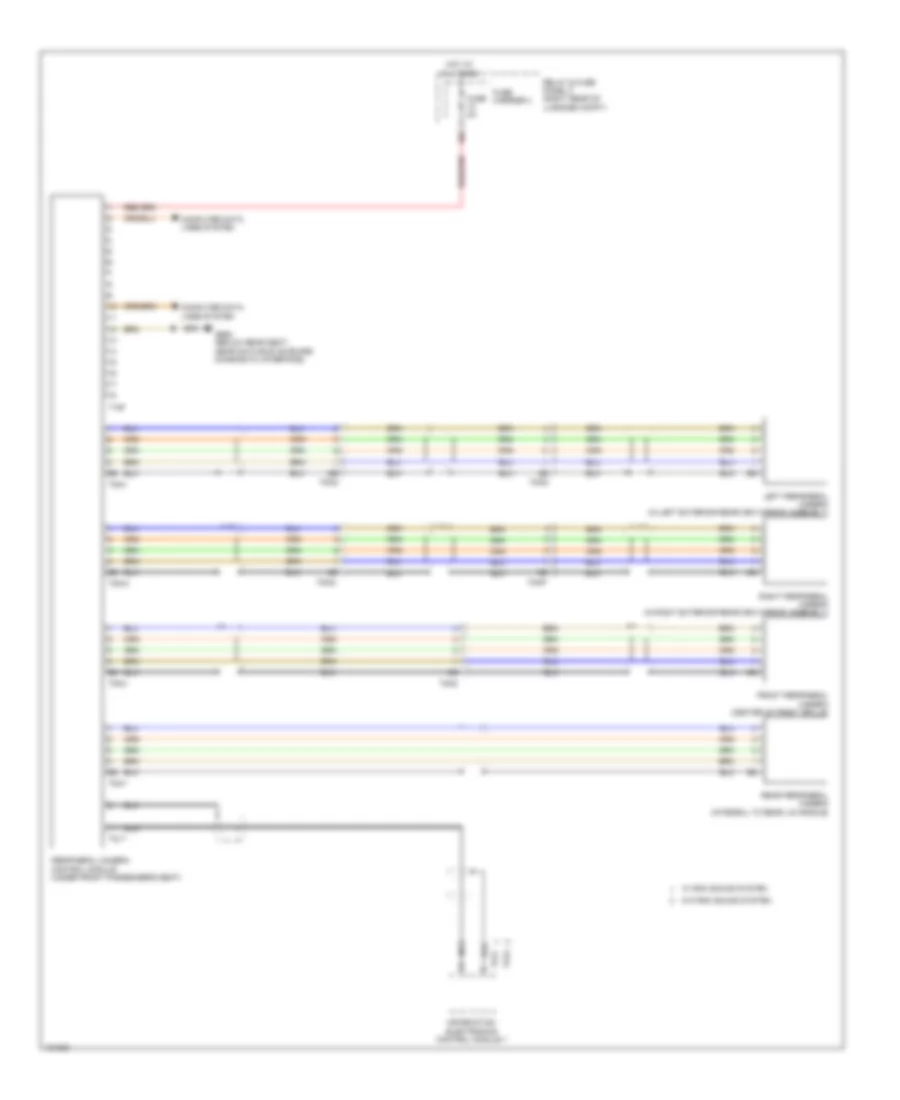
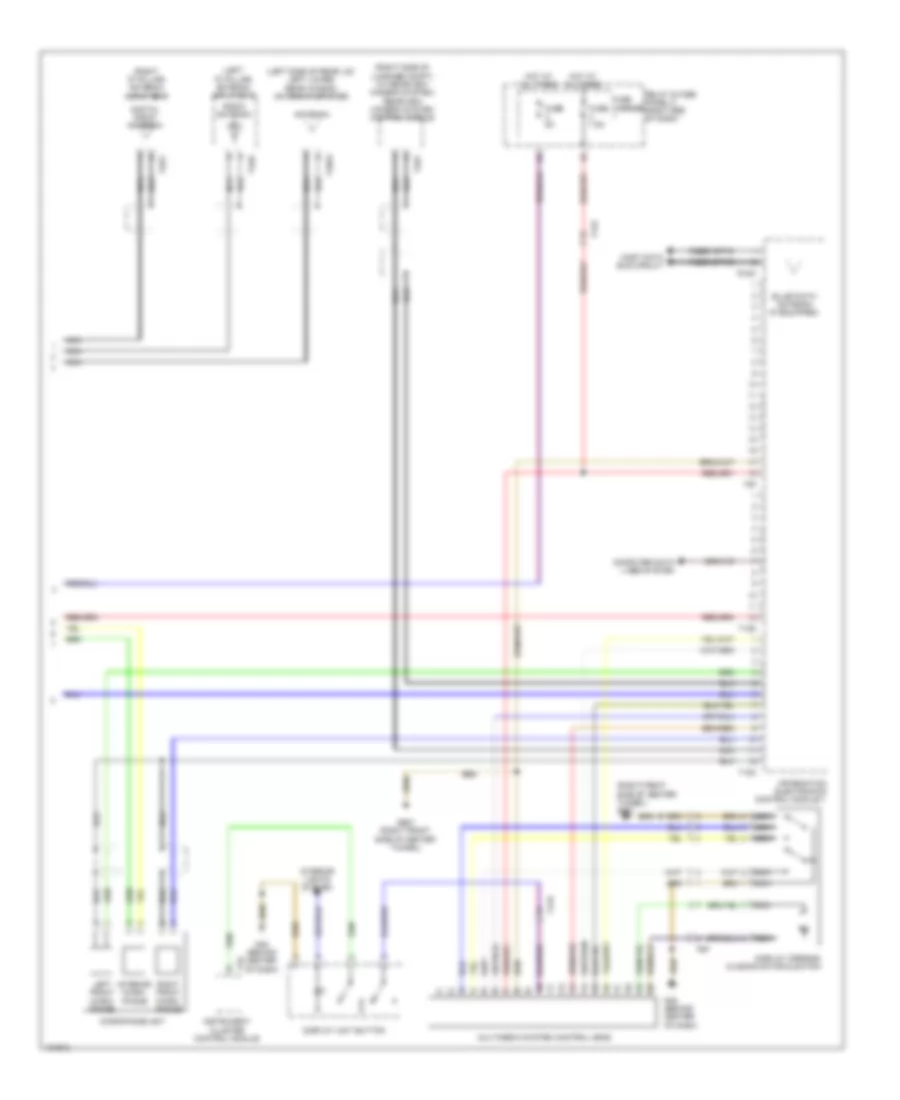
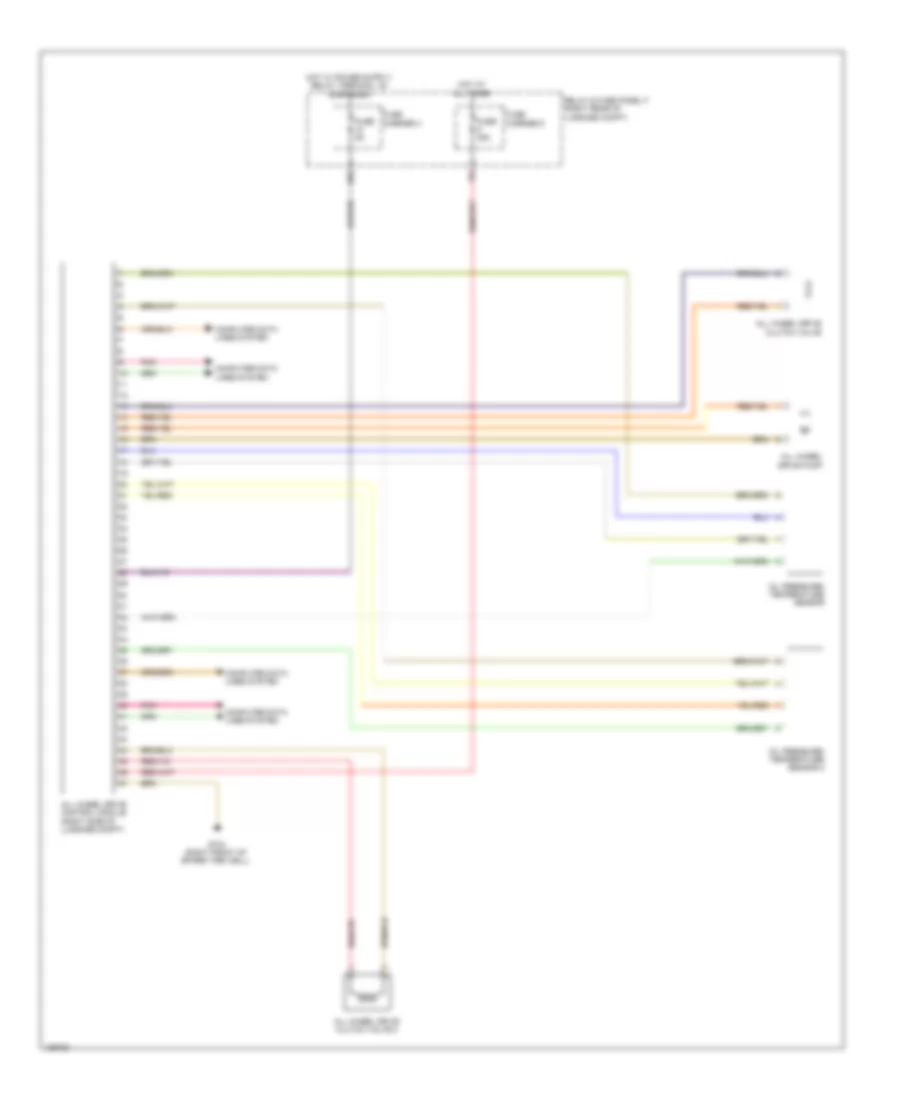
Rear A/C Wiring Diagram for Audi A6 Quattro Prestige 2014
List of elements for Rear A/C Wiring Diagram for Audi A6 Quattro Prestige 2014:
- 11a
- Computer data lines system
- Fuse 10a
- Fuse 30a
- Fuse carrier
- G44 (behind left kick panel)
- G687 (right front side of center tunnel)
- Hot at all times
- Interior lights system
- Left rear footwell vent temperature sensor (in left rear footwell vent assembly)
- Left rear upper body vent motor (left side of upper body vent assembly)
- Left rear upper body vent temperature sensor (in rear upper body vent assembly)
- Power distribution system
- Rear a/c display control head
- Red
- Relay & fuse panel b (left end of dash)
- Relay & fuse panel f (right rear of luggage compt)
- Right rear footwell vent temperature sensor (in right rear footwell vent assembly)
- Right rear upper body vent motor (right side of upper body vent assembly)
- Right rear upper body vent temperature sensor (in rear upper body vent assembly)
- Right/left rear upper body vent position sensor (in rear upper body vent assembly)
- Seats system
- T20a
- T3r
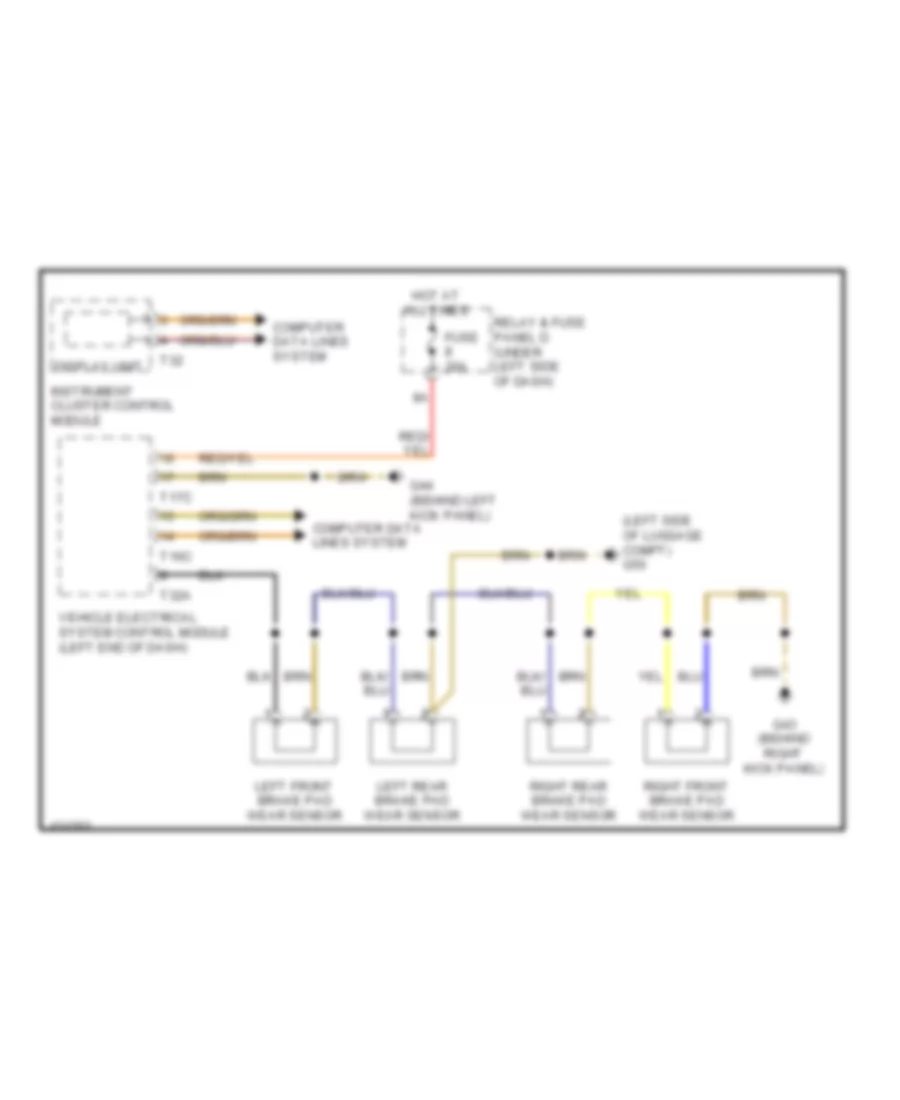
ANTI-LOCK BRAKES
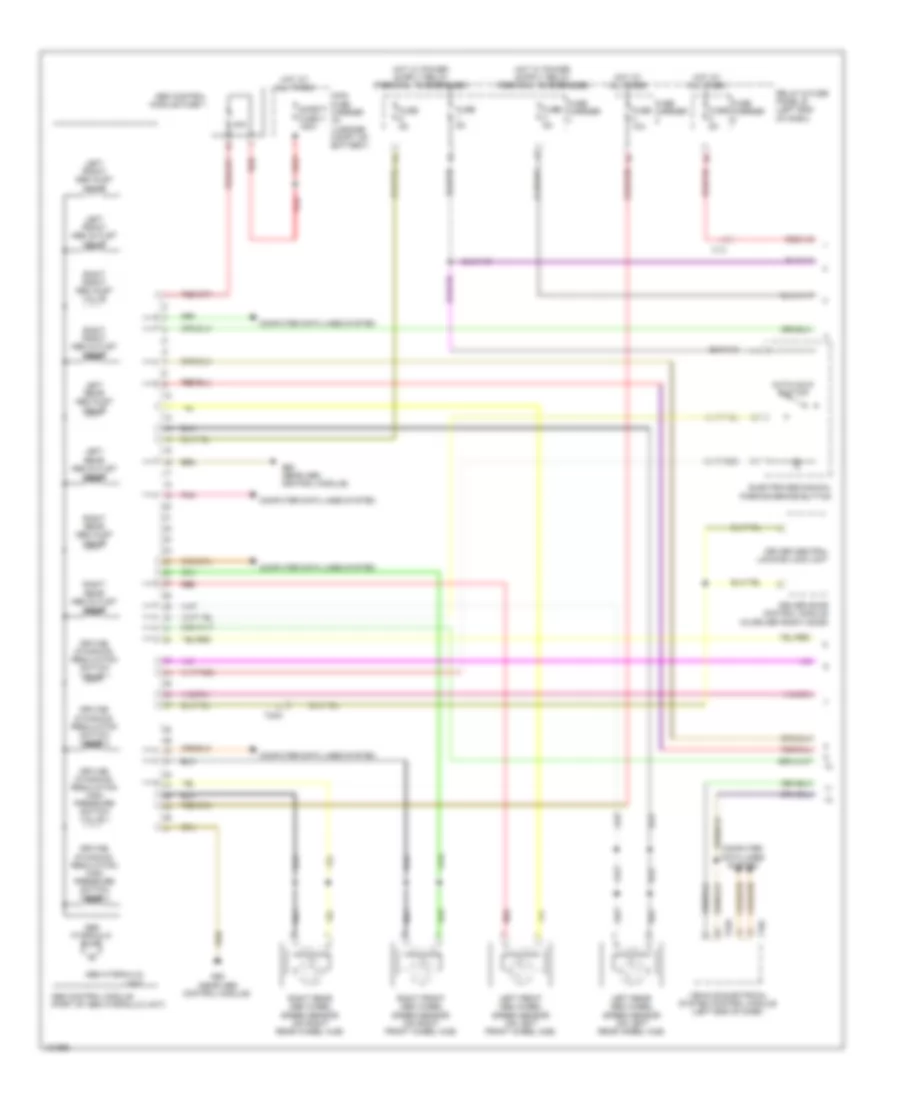
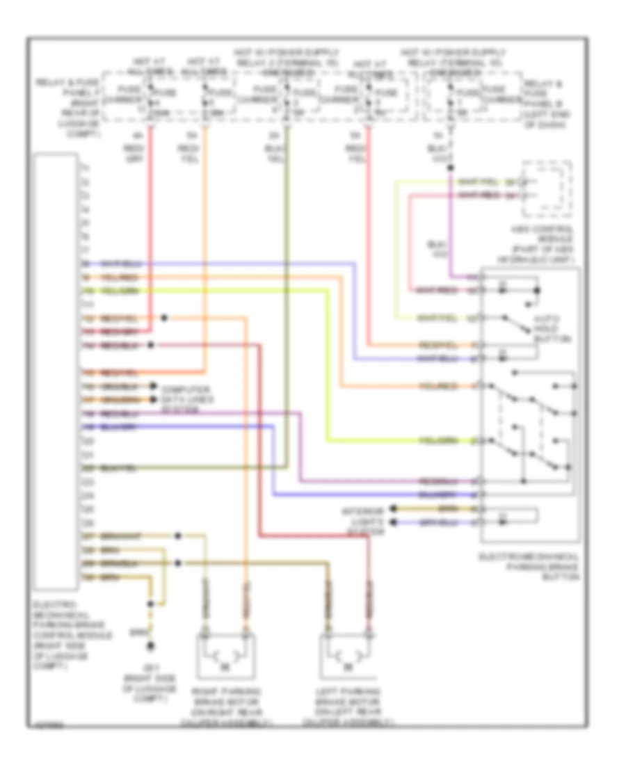
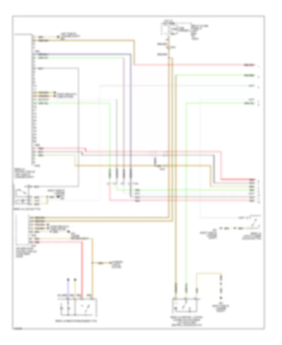
Anti-lock Brakes Wiring Diagram (1 of 2) for Audi A6 Quattro Prestige 2014
List of elements for Anti-lock Brakes Wiring Diagram (1 of 2) for Audi A6 Quattro Prestige 2014:
- 40a
- Abs control module (part of abs hydraulic unit)
- Abs control module fuse 1
- Abs hydraulic pump
- Abs hydraulic unit
- Auto hold button
- Computer data lines system
- Driver central locking lock unit
- Driver door control module (in driver front door)
- Driving dynamics regulation high pressure switch valve 1
- Driving dynamics regulation high pressure switch valve 2
- Driving dynamics regulation switch valve 1
- Driving dynamics regulation switch valve 2
- Electro-mechanical parking brake button
- Fuse 10a
- Fuse 5a
- Fuse carrier
- G55 (near abs control module)
- Hot at all times
- Left front abs inlet valve
- Left front abs outlet valve
- Left front abs wheel speed sensor (on left front wheel hub)
- Left rear abs inlet valve
- Left rear abs outlet valve
- Left rear abs wheel speed sensor (on left rear wheel hub)
- Main fuse carrier (in luggage compt on battery)
- Pnk
- Red
- Relay & fuse panel b (left end of dash)
- Right front abs inlet valve
- Right front abs outlet valve
- Right front abs wheel speed sensor (on right front wheel hub)
- Right rear abs inlet valve
- Right rear abs outlet valve
- Right rear abs wheel speed sensor (on right rear wheel hub)
- Safety fuse 3 150a
- T16c
- T17i
- T23a
- T32a
- Vehicle electrical system control module (left end of dash)
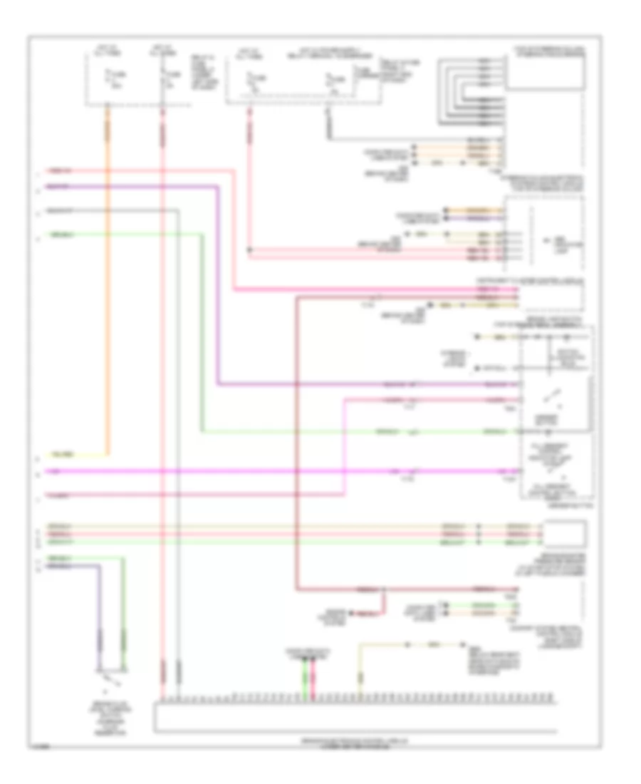
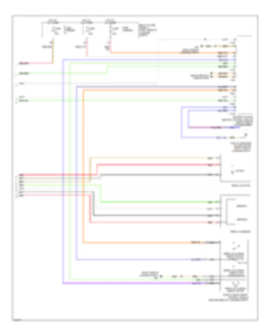
Anti-lock Brakes Wiring Diagram (2 of 2) for Audi A6 Quattro Prestige 2014
List of elements for Anti-lock Brakes Wiring Diagram (2 of 2) for Audi A6 Quattro Prestige 2014:
- (top of steering column) steering angle sensor
- Abs indicator lamp
- Asr/esp button
- Brake booster pressure sensor (w/ start/stop system) (in left plenum chamber)
- Brake fluid level warning switch (on brake fluid reservoir)
- Brake lamp switch (top of brake pedal assembly)
- Comfort system central control module (right side of luggage compt)
- Computer data lines system
- Engine controls system
- Fuse 20a
- Fuse 5a
- Fuse carrier
- G45 (behind center of dash)
- G688 (below rear seat, near data bus on board diagnostic interface)
- Hill descent control button (awd)
- Hill descent control indicator lamp (awd)
- Hot at all times
- Instrument cluster control module
- Interior lights system
- Nca
- Pnk
- Relay & fuse panel c (right end of dash)
- Relay & fuse panel d (under left side of dash)
- Sensor electronics control module (under center console)
- Steering column electronic systems control module (top of steering column)
- Switch illumination bulb
- T10k
- T16e
- T17i
- T17o
- T32g
- T32i
- T6ai
ANTI-THEFT
Anti-theft Wiring Diagram (1 of 6) for Audi A6 Quattro Prestige 2014
List of elements for Anti-theft Wiring Diagram (1 of 6) for Audi A6 Quattro Prestige 2014:
- (w/ anti-theft alarm system & interior monitoring & towing prevention) alarm system deactivation switch
- Anti-lock brakes system
- Central locking safe indicator lamp
- Computer data lines system
- Driver central locking lock unit (w/ door closing aid)
- Driver central locking lock unit (w/o door closing aid)
- Driver door central locking system motor
- Driver door closing assist motor (if equipped)
- Driver door contact switch
- Driver interior locking switch
- Driver lock cylinder contact switch
- Driver's door control module (in driver door)
- Fuse 30a
- Fuse carrier
- G34 (under driver's seat)
- Hot at all times
- Interior lights system
- Left front central locking system actuator
- Rear lid remote release button
- Red
- Relay & fuse panel b (left end of dash)
- T10w
- T20e
- T23a
- T27c
- T32k
- T3au
- W/ door closing aid
- W/o door closing aid
Anti-theft Wiring Diagram (2 of 6) for Audi A6 Quattro Prestige 2014
List of elements for Anti-theft Wiring Diagram (2 of 6) for Audi A6 Quattro Prestige 2014:
- (in left rear door) left rear door control module
- (under front passenger's seat) g35
- Fuse 30a
- Fuse carrier
- G34 (under driver's seat)
- Hot at all times
- Interior lights system
- Left rear interior locking switch
- Relay & fuse panel f (right rear of luggage compt)
- Right rear closing assist motor (if equipped)
- Right rear door control module (in right rear door)
- Right rear interior locking switch
- T16n
- T16o
- T20g
- T20h
- T23a
- T270
- T27c
- T27d
Anti-theft Wiring Diagram (3 of 6) for Audi A6 Quattro Prestige 2014
List of elements for Anti-theft Wiring Diagram (3 of 6) for Audi A6 Quattro Prestige 2014:
- (w/ door closing aid) left rear central locking lock unit
- (w/o door closing aid) left rear central locking lock unit
- Computer data lines system
- G34 (under driver's seat)
- G35 (under front passenger's seat)
- Instrument cluster control module
- Interior access/start authorization antenna 2 (center rear of luggage compt)
- Left rear central locking system actuator
- Left rear central locking system motor
- Left rear child safety lock contact switch
- Left rear child safety lock motor
- Left rear closing assist motor (if equipped)
- Left rear door contact switch
- Right rear central locking lock unit (w/ door closing aid)
- Right rear central locking lock unit (w/o door closing aid)
- Right rear central locking system actuator
- Right rear child m
- Right rear child safety lock contact switch
- Right rear child safety lock motor
- Right rear door central locking system motor
- Right rear door contact switch
- Safety lock motor
- T10aa
- T10z
- T32
- T3aw
- T3ax
- W/ door closing aid
- W/o door closing aid
Anti-theft Wiring Diagram (4 of 6) for Audi A6 Quattro Prestige 2014
List of elements for Anti-theft Wiring Diagram (4 of 6) for Audi A6 Quattro Prestige 2014:
- (right side of luggage compt) comfort system central control module
- Access/start authorization button
- Antenna amplifier 2 (left "d" pillar)
- Anti-theft immobilizer reader coil (center of dash)
- C (right end of dash)
- Central locking & anti-theft alarm system antenna
- Computer data lines system
- Door closing assist control module (center rear of luggage compt)
- Fuel filler door unlock motor (right side of luggage compt)
- Fuse 20a
- Fuse 5a
- Fuse carrier
- G34 (under driver's seat)
- G35 (under front passenger's seat)
- G45 (behind center of dash)
- G51 (right side of luggage compt)
- G687 (right front side of center tunnel)
- Hot at all times
- Interior access/start authorization antenna 1 (under center console)
- Left access/start authorization antenna (in left rear door)
- Left front exterior door handle touch sensor (in left front door handle assembly)
- Left rear exterior door handle touch sensor (in left rear door handle assembly)
- Nca
- Rear lid closing assist motor
- Rear lid closing assist/lock stop switch
- Rear lid closing assist/unlock stop switch
- Rear lid lock cylinder unlock button
- Rear lid lock/ alarm/central locking switch & rear lid central locking system motor
- Relay & fuse panel
- Relay & fuse panel f (right rear of luggage compt)
- Right access/start authorization antenna (in right rear door)
- Right front exterior door handle touch sensor (in right front door handle assembly)
- Right rear exterior door handle touch sensor (in right rear door handle assembly)
- T17h
- T17r
- T17s
- T23a
- T23b
- T27c
- T27d
- T2co
- T32g
- T32h
- T32i
Anti-theft Wiring Diagram (5 of 6) for Audi A6 Quattro Prestige 2014
List of elements for Anti-theft Wiring Diagram (5 of 6) for Audi A6 Quattro Prestige 2014:
- (in right plenum chamber) alarm horn
- (in roof console) (w/ interior monitoring) anti-theft alarm system sensor
- (in steering column) electronic steering column lock control module
- (left end of dash) vehicle electrical system control module
- Computer data lines system
- Engine hood contact switch (center front of engine compt)
- Front passenger interior locking switch
- Fuse 5a
- Fuse carrier
- G43 (behind right kick panel)
- G44 (behind left kick panel)
- G45 (behind center of dash)
- G50 (left side of luggage compt)
- G51 (right side of luggage compt)
- Hood contact switch 2
- Horns system
- Hot at all times
- Interior lights system
- Nca
- Rear lid control module (left side of luggage compt)
- Rear lid lock button in luggage compartment
- Relay & fuse panel c (right end of dash)
- Relay & fuse panel d (under left side of dash)
- Selector lever sensor system control module (base of shift lever assembly)
- T16c
- T170
- T17c
- T26b
- T2af
- T2ay
- T32a
- T32c
- T4bx
- W/ interior monitoring
Anti-theft Wiring Diagram (6 of 6) for Audi A6 Quattro Prestige 2014
List of elements for Anti-theft Wiring Diagram (6 of 6) for Audi A6 Quattro Prestige 2014:
- (under front passenger's seat) g35
- Computer data lines system
- Front passenger central locking lock unit (w/ door closing aid)
- Front passenger central locking lock unit (w/o door closing aid)
- Front passenger closing assist motor (if equipped)
- Front passenger door central locking system motor
- Front passenger door contact switch
- Front passenger door control module (in front passenger door)
- Fuse 30a
- Fuse carrier
- G35 (under front passenger's seat)
- Hot at all times
- Relay & fuse panel f (right rear of luggage compt)
- Right front central locking system actuator
- T20f
- T23b
- T32l
- T3av
- T8x
- W/ door closing aid
- W/o door closing aid
BODY CONTROL MODULES
Comfort System Central Control Module Wiring Diagram for Audi A6 Quattro Prestige 2014
List of elements for Comfort System Central Control Module Wiring Diagram for Audi A6 Quattro Prestige 2014:
- Anti-theft system
- Comfort system central control module (right side of luggage compt)
- Computer data lines system
- Defogger system
- Door locks & anti-theft systems
- Door locks & transmissions system
- Door locks system
- Engine controls & transmissions systems
- Engine controls system
- Exterior lights & mirrors systems
- Exterior lights system
- Fuse 20a
- Fuse 30a
- Fuse carrier 1
- Fuse carrier 2
- G51 (right side of luggage compt)
- Hot at all times
- Nca
- Power distribution system
- Power windows system
- Relay & fuse panel f (right rear of luggage compt)
- T17r
- T17s
- T2co
- T32g
- T32h
- T32i
- Transmissions system
- Trunk, tailgate, fuel doors & interior lights systems
- Trunk, tailgate, fuel doors system
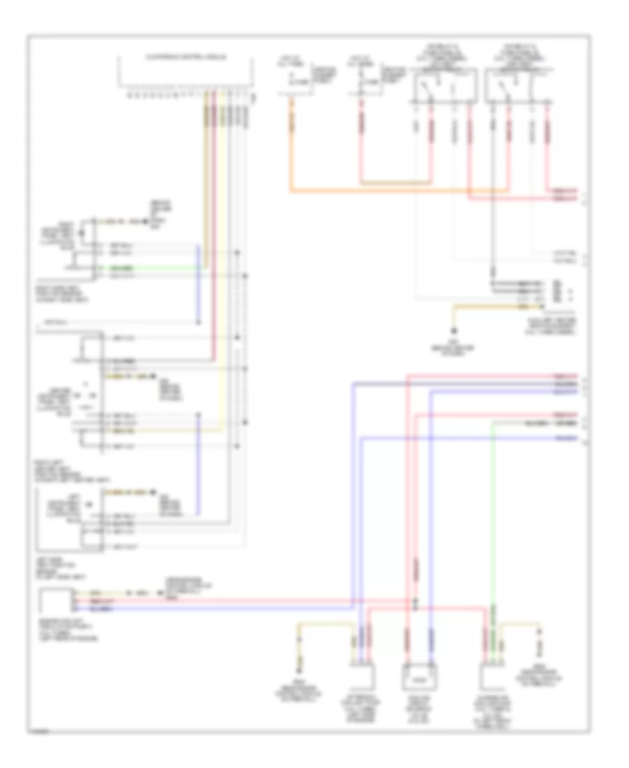
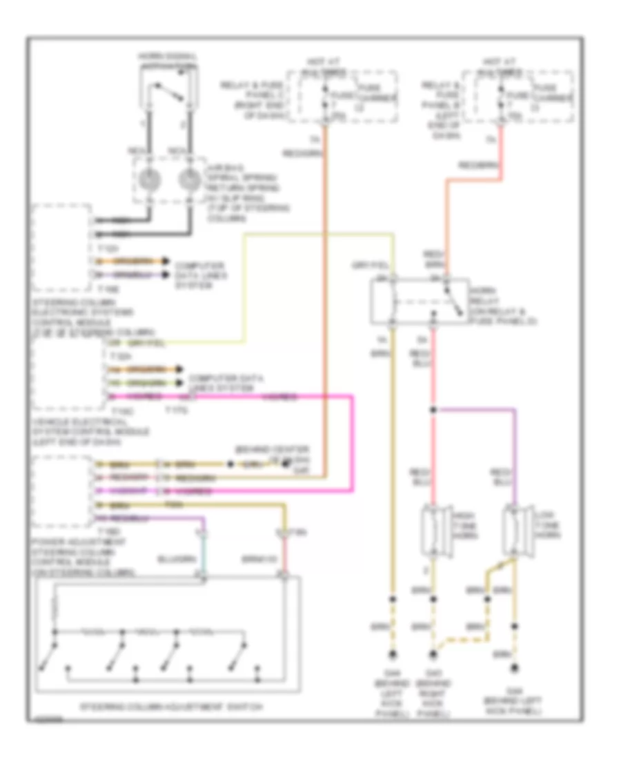
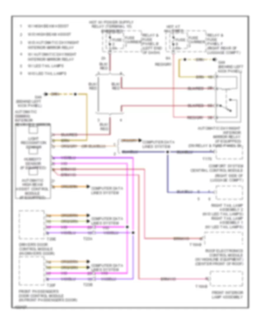
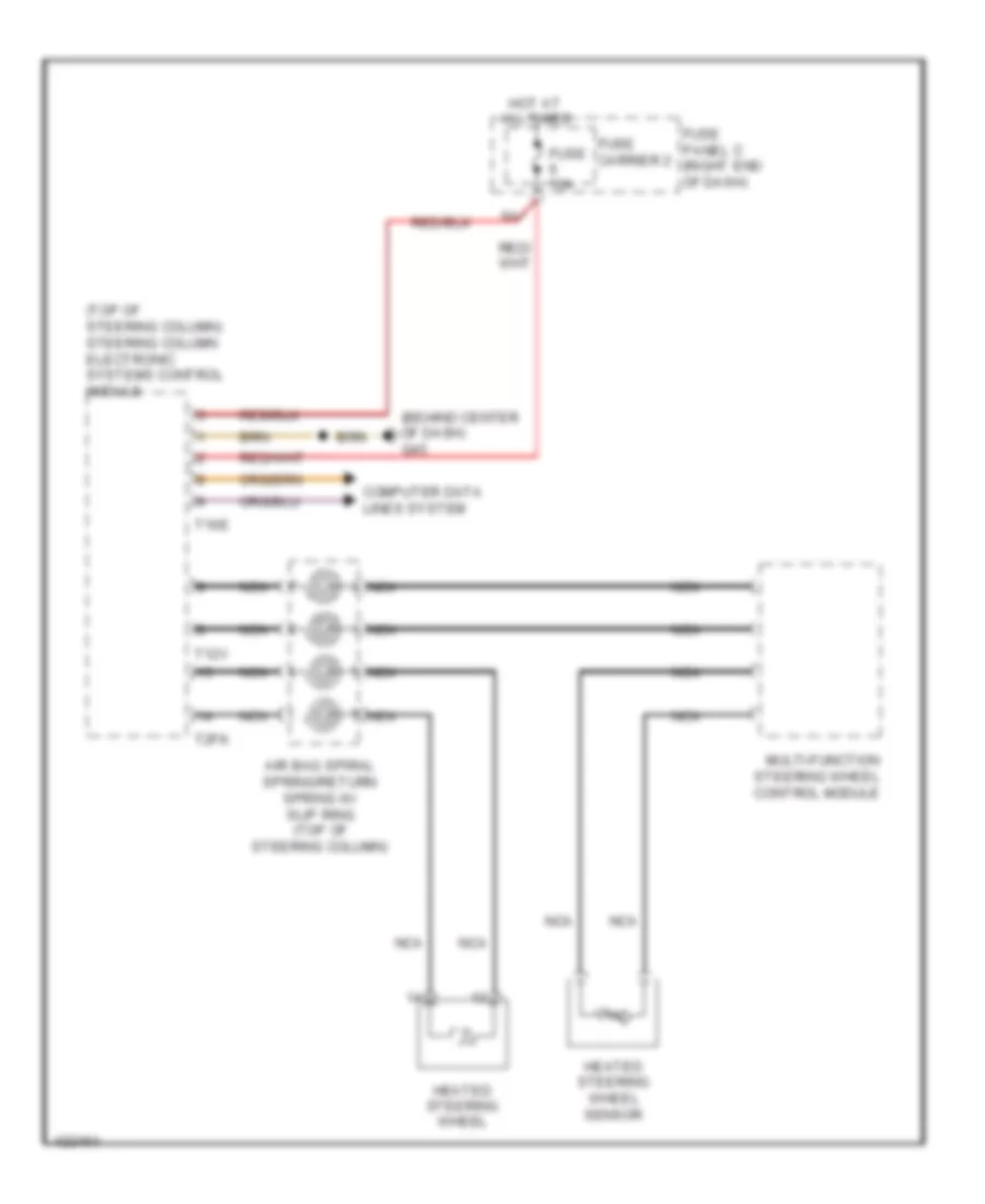
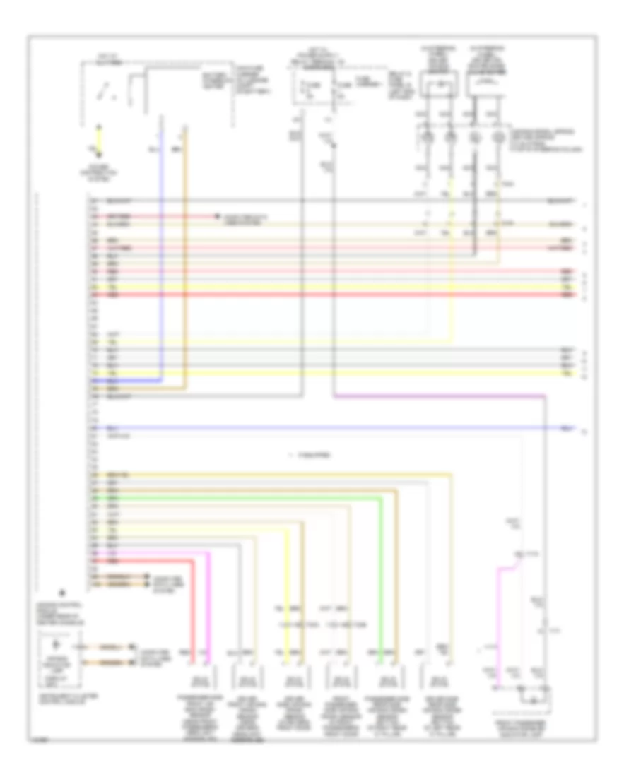
Steering Column Electronic Systems Control Module Wiring Diagram for Audi A6 Quattro Prestige 2014
List of elements for Steering Column Electronic Systems Control Module Wiring Diagram for Audi A6 Quattro Prestige 2014:
- (behind center of dash) g45
- (top of steering column) air bag spiral spring/return spring w/ slip ring
- (w/ lane assist) directional stabilization assistance button
- Air bag control module (under rear of center console)
- Computer data lines system
- Cruise control/ turn signal/ headlamp flasher switch
- Driver air bag igniter (in steering wheel)
- Driver air bag igniter 2
- Engine controls system
- Fuse 10a
- Fuse 5a
- Fuse carrier 1
- Fuse carrier 2
- G45 (behind center of dash)
- Heated steering wheel (if equipped)
- Heated steering wheel sensor
- Horn signal activation
- Hot at all times
- Left multi-function button
- Mode
- Multi-function steering wheel control module
- Nca
- Relay & fuse panel c (right end of dash)
- Right multi-function button
- Steering angle sensor (top of steering column)
- Steering column electronics control module (top of steering column)
- T100
- T12v
- T13b
- T16e
- T17p
- T2fk
- T4ah
- T6am
- Tiptronic downshift button
- Tiptronic upshift button
- W/ heated steering wheel
- Windshield wiper intermittent mode switch
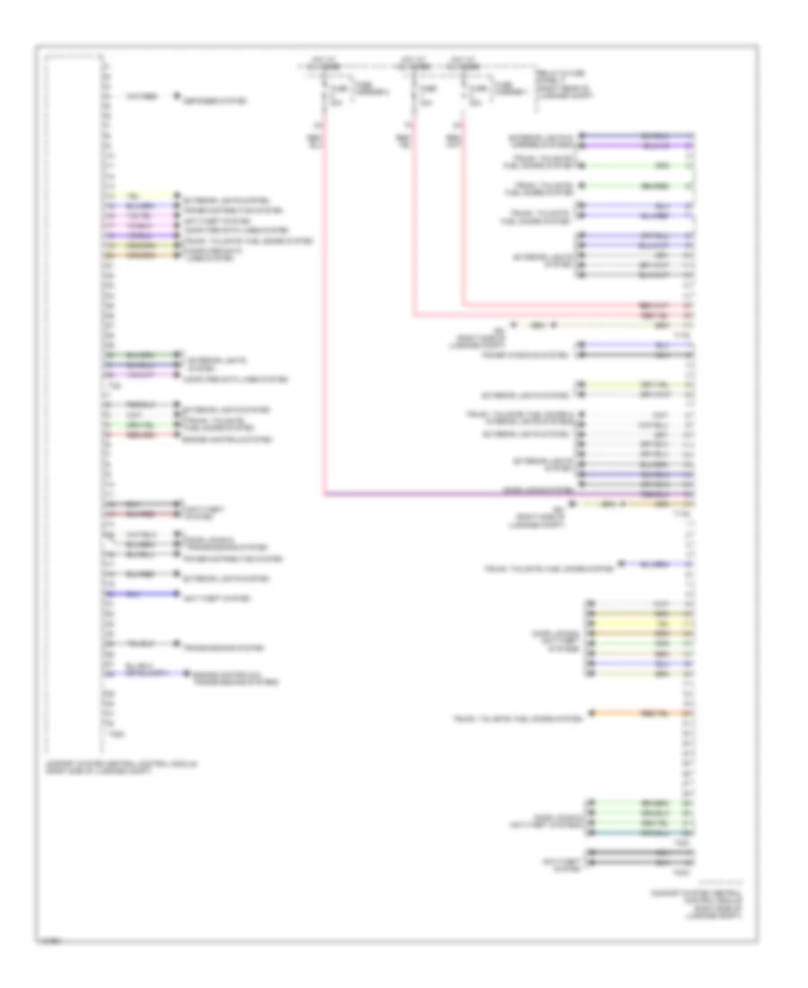
Vehicle Electrical System Control Module Wiring Diagram for Audi A6 Quattro Prestige 2014
List of elements for Vehicle Electrical System Control Module Wiring Diagram for Audi A6 Quattro Prestige 2014:
- (behind center of dash) g45
- 10a
- Air conditioning system
- Air conditioning, instrument cluster, wiper/washer & seats systems
- Anti-theft system
- Computer data lines system
- Door locks system
- Door locks, anti-theft & transmissions systems
- Electronic power steering system
- Exterior lights system
- Exterior lights system headlights & exterior lights system
- Fuse 20a
- Fuse 30a
- Fuse 35a
- Fuse 5a
- Fuse carrier 4
- G44 (behind left kick panel)
- Headlights & exterior lights system
- Headlights system
- Headlights, exterior lights & interior lights systems
- Horns system
- Hot at all times
- Instrument cluster system
- Interior lights system
- Interior lights system headlights, exterior lights & interior lights systems
- Power distribution system
- Power windows system
- Relay & fuse panel d (under left side of dash)
- Relay & fuse panel f (right rear of luggage compt)
- Seats system
- T12k
- T16c
- T17c
- T17d
- T17e
- T32a
- T32c
- T6d
- Valet parking lock button
- Vehicle electrical system control module (left end of dash)
- Warning systems
- Wiper/washer system
COMPUTER DATA LINES
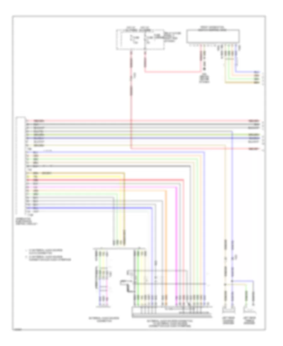
Computer Data Lines Wiring Diagram (1 of 4) for Audi A6 Quattro Prestige 2014
List of elements for Computer Data Lines Wiring Diagram (1 of 4) for Audi A6 Quattro Prestige 2014:
- & 4.0l turbo
- (base of automatic day/ night interior mirror assembly) camera control module
- (if equipped) left front seat ventilation control module
- (in left plenum chamber) engine control module
- (left rear of luggage compt) digital sound system control module
- (on a/c high pressure line) a/c pressure temperature sensor
- (on automatic day/night interior mirror assembly) (w/ high beam assist) automatic dimming interior rearview mirror/ high beam assist control module
- (part of abs hydraulic unit) abs control module
- (top of steering column) steering column electronics control module
- (under transmission oil pan) transmission control module
- (w/ long wheelbase) passenger side rear multicontour seat control module
- 10h
- 10l
- 11h
- 11l
- 12h
- 12l
- 13h
- 13l
- 14h
- 14l
- 15h
- 15l
- 16h
- 16l
- 17h
- 17l
- 18h
- 18l
- 19h
- 19l
- 2.0l turbo &
- 20h
- 20l
- 21h
- 21l
- 22h
- 22l
- 23h
- 23l
- 3.0l sc
- 3.0l turbo diesel
- 7-speed a/t
- 8-speed a/t
- Active steering control module (under driver's seat)
- Bose
- Cvt
- Digital tv tuner (if equipped) (left side of luggage compt)
- Driver door control module (in driver front door)
- Driver multicontour seat control module
- Driver side rear multicontour seat control module (w/ long wheelbase)
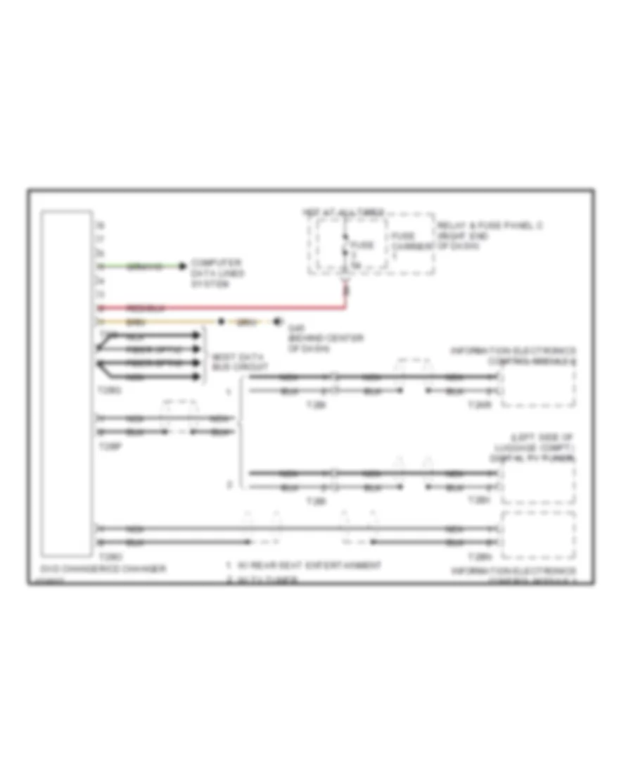
- Dvd & cd changer (if equipped)
- Garage door opener control module (if equipped) (behind center of front bumper cover)
- Humidity sensor in fresh air intake duct
- Information electronics control module 1
- Information electronics control module 2
- Left can-bus disconnection plug
- Memory seat/ steering column adjustment control module
- Nca
- Night vision system control module
- Radio
- T10c
- T10i
- T12a
- T12af
- T12d
- T12y
- T16c
- T16e
- T17a
- T17g
- T17i
- T17m
- T17u
- T17v
- T17w
- T20e
- T23a
- T32e
- T32m
- T38
- T6az
- T6bu
- T6bv
- T6h
- T8al
- T8h
- T8q
- T91
- T94
- Vehicle electrical system control module (left end of dash)
- W/ bang & olufson sound
- W/ sound system
- W/o sound system
Computer Data Lines Wiring Diagram (2 of 4) for Audi A6 Quattro Prestige 2014
List of elements for Computer Data Lines Wiring Diagram (2 of 4) for Audi A6 Quattro Prestige 2014:
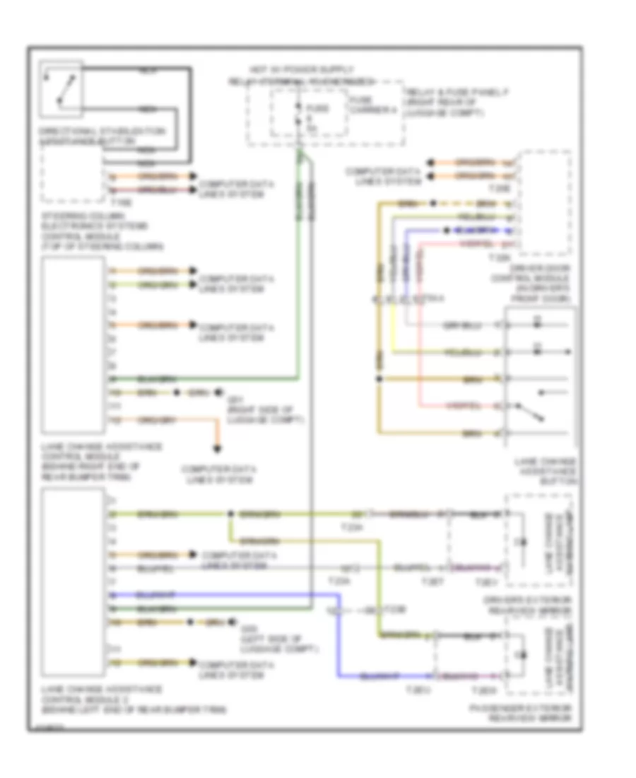
- (behind right end of rear bumper trim) (if equipped) lane change assistance control module
- (behind right front wheel housing liner) (4.0l) subframe mount control module
- (in driver's seat belt retractor assembly)
- (in front passenger's seat belt retractor assembly)
- (in left plenum chamber) wiper motor control module
- (left end of dash) (w/ dynamic cornering lamp) headlamp range/ cornering lamp control module
- (left end of dash) headlamp range control module
- (right side of luggage compt) all wheel drive control module
- (right side of luggage compt) electro- mechanical parking brake control module
- (under rear of center console) air bag control module
- (w/ seat belt warning system) left front seat belt tensioner control module
- (w/ seat belt warning system) right front seat belt tensioner control module
- (w/ special interface functions) 12 pin connector
- Auxiliary heater control module (if equipped) (on auxiliary heater assembly)
- Climatronic control module
- Comfort system central control module (right side of luggage compt)
- Electronic steering column lock control module (in steering column)
- Front passenger door control module (in passenger's front door)
- Front passenger memory seat control module
- Front passenger multicontour seat control module
- Instrument cluster control module
- Left headlamp assembly
- Nca
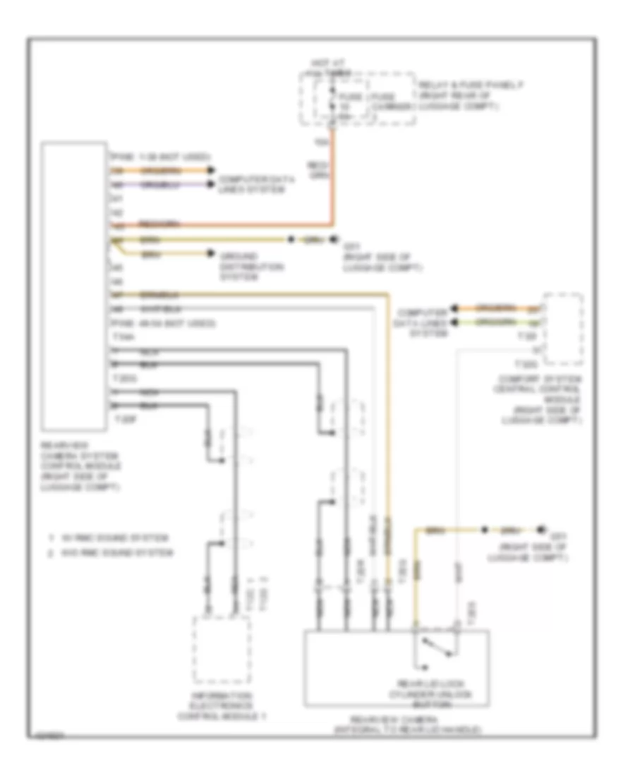
- Rear a/c display control head (if equipped)
- Rear view camera system control module (if equipped) (right side of luggage compt)
- Special purpose vehicle control module (w/ special purpose vehicles)
- T12ab
- T12o
- T16t
- T17h
- T17n
- T17o
- T20a
- T20c
- T20f
- T23b
- T2db
- T32
- T32i
- T32n
- T54a
- T6ba
- T6k
- Towing recognition control module (w/ trailer setup) (right side of luggage compt)
- Windshield projection head up display control module (if equipped) (top left side of dash)
Computer Data Lines Wiring Diagram (3 of 4) for Audi A6 Quattro Prestige 2014
List of elements for Computer Data Lines Wiring Diagram (3 of 4) for Audi A6 Quattro Prestige 2014:
- (anti-theft alarm system sensor: in roof console) anti-theft alarm system sensor/interior monitoring sensor/vehicle inclination sensor
- (behind left end of rear bumper trim) lane change assistance control module 2
- (below front left headlamp) distance regulation control module 2
- (below front right headlamp) distance regulation control module
- (center front of roof) power sun-roof control module
- (center rear of roof) roof shade control module
- (if equipped) right front seat ventilation control module
- Abs control module (part of abs hydraulic unit)
- Anti-theft immobilizer reader coil (center of dash)
- Data link connector (under left side of dash)
- Fuse 10a
- Fuse 5a
- Fuse carrier
- G45 (behind center of dash)
- Garage door opener control head (if equipped)
- Hot at all times
- Image processing control module (under front passenger's seat)
- Parking aid control module (right side of luggage compt)
- Pnk
- Rain/light recognition sensor (in automatic day/night interior mirror assembly)
- Rear lid control module (left side of luggage compt)
- Relay & fuse panel c (right end of dash)
- Relay & fuse panel f (right rear of luggage compt)
- Right headlamp assembly
- Roof electronics control module (if equipped) (center front of roof)
- T10ab
- T12i
- T16i
- T17i
- T17o
- T26b
- T4u
- T6g
- T6i
- W/ adaptive cruise control
- W/o adaptive cruise control
Computer Data Lines Wiring Diagram (4 of 4) for Audi A6 Quattro Prestige 2014
List of elements for Computer Data Lines Wiring Diagram (4 of 4) for Audi A6 Quattro Prestige 2014:
- (below center of rear seat) data bus on board diagnostic interface
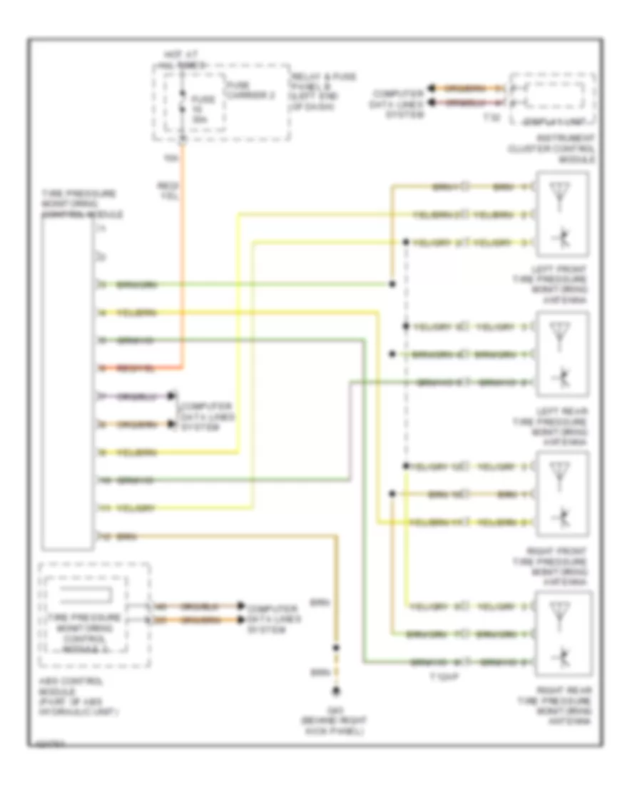
- (if equipped) tire pressure monitoring control module
- 10h
- 10l
- 11h
- 11l
- 12h
- 12l
- 13h
- 13l
- 14h
- 14l
- 15h
- 15l
- 16h
- 16l
- 17h
- 17l
- 18h
- 18l
- 19h
- 19l
- 20h
- 20l
- 21h
- 21l
- 22h
- 22l
- 23h
- 23l
- All wheel drive control module (right side of luggage compt)
- Battery monitoring control module (on battery)
- Fuse 5a
- Fuse carrier
- G688 (below rear seat, near data bus on board diagnostic interface)
- Generator & voltage regulator
- Hot at all times
- Level control system control module (right side of luggage compt)
- Nca
- Peripheral camera control module (if equipped) (under front passenger's seat)
- Pnk
- Power steering control module (on steering box)
- Relay & fuse panel b (left end of dash)
- Right can-bus disconnection plug
- Sensor electronics control module (under center console)
- Sound systems
- System & rear final drive-sport differential
- System & w/ rear final drive-sport differential
- T17a
- T2aq
- T32b
- T6ak
- T6al
- T6w
- Voltage stabilizer (w/ stop/ start system) (in spare tire well)
- W/ level control system
- W/ rear final drive-sport differential
- W/o level control
- W/o rear final drive-sport differential
COOLING FAN
Cooling Fan Wiring Diagram (1 of 2) for Audi A6 Quattro Prestige 2014
List of elements for Cooling Fan Wiring Diagram (1 of 2) for Audi A6 Quattro Prestige 2014:
- (near engine control module on firewall) g645
- (or red)
- 11a
- 16a
- After-run coolant pump (4.0l turbo) (left side of engine)
- Charge air cooling pump (4.0l turbo & 3.0l sc) (in left front wheelwell)
- Climatronic control module
- Computer data lines system
- Coolant recirculation pump (except 2.0l turbo & w/o parking heater)
- Coolant shut-off valve (except 2.0l turbo & w/o parking heater)
- Cooling circuit solenoid valve (3.0l sc)
- Engine coolant circulation pump 2 (4.0l turbo) (left rear of engine)
- Engine coolant level (ecl) sensor (in engine coolant reservoir)
- Fuse 15a
- Fuse 5a
- G645 (near engine control module on firewall)
- Red
- Relay & fuse panel a (in left plenum chamber e-box)
- T16c
- T17i
- T20c
- T32a
- Vehicle electrical system control module (left end of dash)
Cooling Fan Wiring Diagram (2 of 2) for Audi A6 Quattro Prestige 2014
List of elements for Cooling Fan Wiring Diagram (2 of 2) for Audi A6 Quattro Prestige 2014:
- (behind left side of radiator) (3.0l sc & 4.0l turbo) coolant fan 2
- (coolant fan 2: behind left side of radiator) (coolant fan: behind right side of radiator) coolant fan/coolant fan 2
- (or red)
- 2.0l turbo
- 3.0l sc
- 3.0l turbo diesel
- 4.0l turbo
- Computer data lines system
- Coolant fan
- Coolant fan 2
- Coolant fan control (fc) control module 2 (3.0l sc & 4.0l turbo) (on right coolant fan motor)
- Coolant fan control (fc) module (on left coolant fan motor)
- Coolant fan fuse 40a/ 60a/ 80a
- Coolant fan second speed fuse 40a/ 60a/ 80a
- Coolant recirculation pump (2.0l turbo)
- Engine control module (ecm) (in left plenum chamber)
- Engine coolant temperature (ect) sensor (2.0l turbo: left side of engine block) (3.0l turbo diesel: top left center of engine) (3.0l sc & 4.0l turbo: front of engine)
- Engine coolant temperature sensor on radiator outlet (3.0l turbo diesel & 4.0l turbo) (4.0l turbo: on lower left hose on radiator) (3.0l turbo diesel: on lower right hose on radiator)
- Engine temperature control sensor (front of left cylinder bank)
- Except 2.0l turbo
- G645 (near engine control module on on firewall)
- G685 (on right front long member)
- Hot at all times
- Nca
- Red
- T105
- T14a
- T14b
- T4fm
- T4fn
- T60
- T91
- T94
- Terminal 30 wire junction (in center plenum chamber)
CRUISE CONTROL
2.0L TURBO
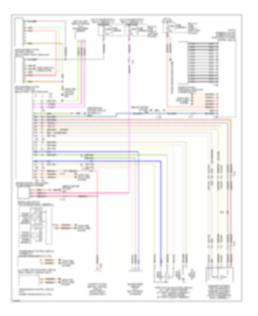
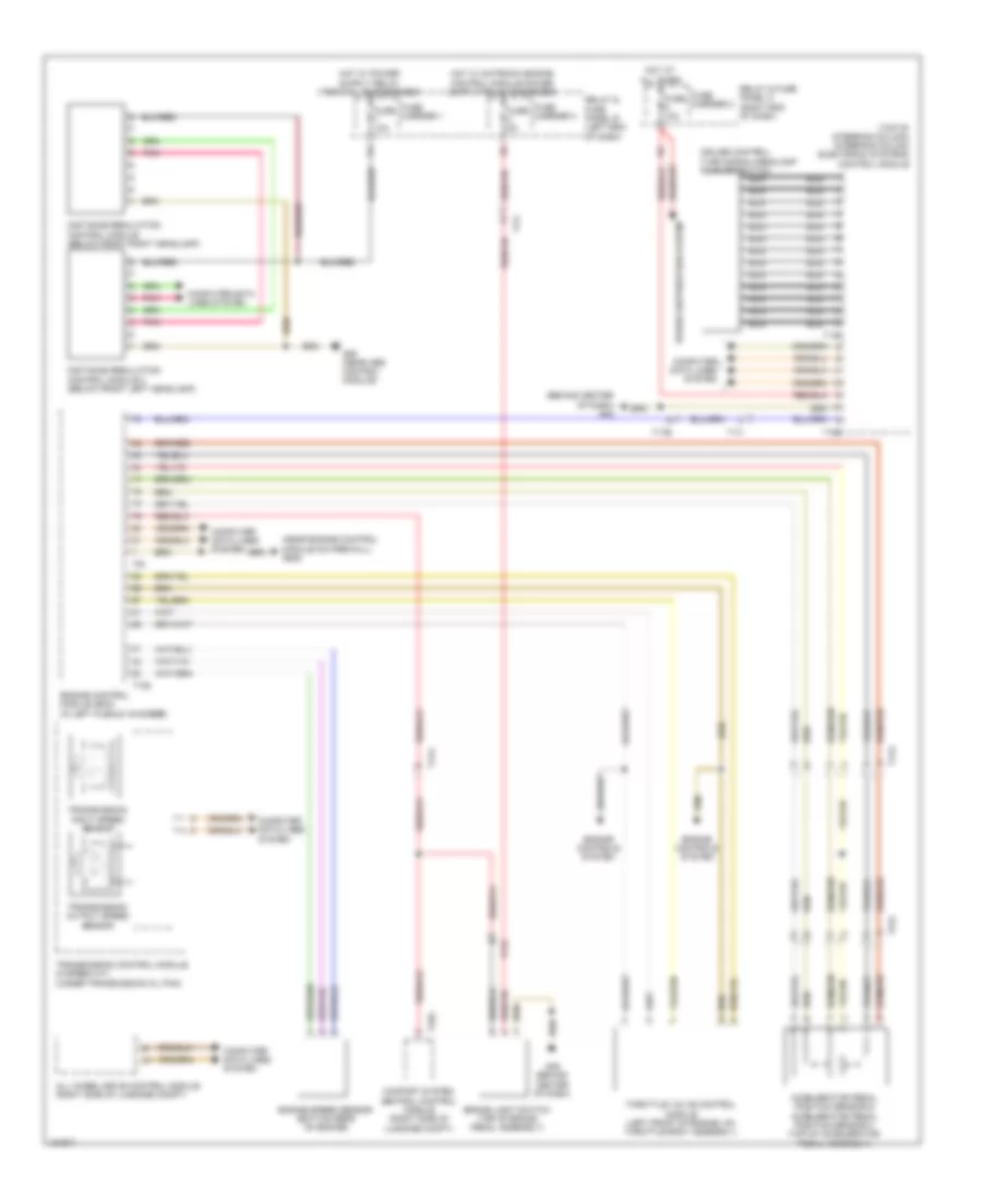
2.0L Turbo, Cruise Control Wiring Diagram for Audi A6 Quattro Prestige 2014
List of elements for 2.0L Turbo, Cruise Control Wiring Diagram for Audi A6 Quattro Prestige 2014:
- (behind center of dash) g45
- (bottom left rear of engine) (2.0l) engine speed sensor
- (near abs control module) g55
- (near engine control module on firewall) g645
- (top of steering column) steering column electronic systems control module
- 2.0l
- 3.0l
- Accelerator pedal position sensor & accelerator pedal position sensor 2 (top of accelerator pedal assembly)
- All-wheel drive control module (right side of luggage compt)
- Brake lamp switch (top of brake pedal assembly)
- Comfort system central control module (right side of luggage compt)
- Computer
- Computer data lines system
- Cruise control/ turn signal/headlamp flasher switch
- Data lines
- Distance regulation control module (below front right headlamp)
- Distance regulation control module 2 (below front left headlamp)
- Drive throttle epc
- Engine control module (ecm) (in left plenum chamber)
- Engine speed sensor (3.0l) (bottom rear of engine)
- Fuse 10a
- Fuse 5a
- Fuse carrier
- Fuse carrier 2
- Hot at all times
- Nca
- Pnk
- Power distribution system
- Relay & fuse panel b (left end of dash)
- Relay & fuse panel c (right end of dash)
- Sensor 1 angle
- Sensor 2 angle
- System
- T13b
- T16e
- T17a
- T17b
- T17h
- T17i
- T17o
- T32g
- T60
- T94
- Throttle valve control module (2.0l: left side of engine, on throttle body assembly) (3.0l: rear of engine, on throttle body assembly)
- Trans- mission input speed sensor
- Trans- mission output speed sensor
- Transmission control module (8 speed a/t) (under transmission oil pan)
- Transmission control module (cvt) (under transmission oil pan)
3.0L SC
3.0L SC, Cruise Control Wiring Diagram for Audi A6 Quattro Prestige 2014
List of elements for 3.0L SC, Cruise Control Wiring Diagram for Audi A6 Quattro Prestige 2014:
- (behind center of dash) g45
- (bottom left rear of engine) (2.0l) engine speed sensor
- (near abs control module) g55
- (near engine control module on firewall) g645
- (top of steering column) steering column electronic systems control module
- 2.0l
- 3.0l
- Accelerator pedal position sensor & accelerator pedal position sensor 2 (top of accelerator pedal assembly)
- All-wheel drive control module (right side of luggage compt)
- Brake lamp switch (top of brake pedal assembly)
- Comfort system central control module (right side of luggage compt)
- Computer
- Computer data lines system
- Cruise control/ turn signal/headlamp flasher switch
- Data lines
- Distance regulation control module (below front right headlamp)
- Distance regulation control module 2 (below front left headlamp)
- Drive throttle epc
- Engine control module (ecm) (in left plenum chamber)
- Engine speed sensor (3.0l) (bottom rear of engine)
- Fuse 10a
- Fuse 5a
- Fuse carrier
- Fuse carrier 2
- Hot at all times
- Nca
- Pnk
- Power distribution system
- Relay & fuse panel b (left end of dash)
- Relay & fuse panel c (right end of dash)
- Sensor 1 angle
- Sensor 2 angle
- System
- T13b
- T16e
- T17a
- T17b
- T17h
- T17i
- T17o
- T32g
- T60
- T94
- Throttle valve control module (2.0l: left side of engine, on throttle body assembly) (3.0l: rear of engine, on throttle body assembly)
- Trans- mission input speed sensor
- Trans- mission output speed sensor
- Transmission control module (8 speed a/t) (under transmission oil pan)
- Transmission control module (cvt) (under transmission oil pan)
3.0L TURBO DIESEL
3.0L Turbo Diesel, Cruise Control Wiring Diagram for Audi A6 Quattro Prestige 2014
List of elements for 3.0L Turbo Diesel, Cruise Control Wiring Diagram for Audi A6 Quattro Prestige 2014:
- (behind center of dash) g45
- (near engine control module on firewall) g645
- (top of steering column) steering column electronic systems control module
- Accelerator pedal position sensor & accelerator pedal position sensor 2 (top of accelerator pedal assembly)
- All wheel drive control module (right side of luggage compt)
- Brake light switch (top of brake pedal assembly)
- Comfort system central control module (right side of luggage compt)
- Computer data lines system
- Cruise control/ turn signal/headlamp flasher switch
- Distance regulation control module (below front right headlamp)
- Distance regulation control module 2 (below front left headlamp)
- Engine control module (ecm) (in left plenum chamber)
- Engine controls system
- Engine speed sensor (bottom rear of engine)
- Fuse 10a
- Fuse 5a
- Fuse carrier 1
- Fuse carrier 2
- Fuse carrier 3
- G45 (behind center of dash)
- G55 (near abs control module)
- Hot at all times
- Nca
- Pnk
- Power distribution system
- Relay & fuse panel b (left end of dash)
- Relay & fuse panel c (right end of dash)
- T105
- T13b
- T16e
- T17a
- T17b
- T17h
- T17i
- T17o
- T32g
- T91
- Throttle valve control module (left front of engine, on throttle body assembly)
- Transmission control module (8 speed a/t) (under transmission oil pan)
- Transmission input speed sensor
- Transmission output speed sensor
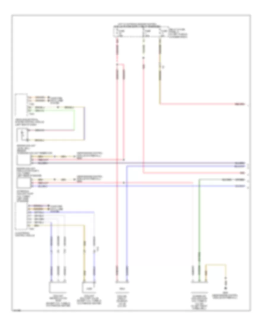
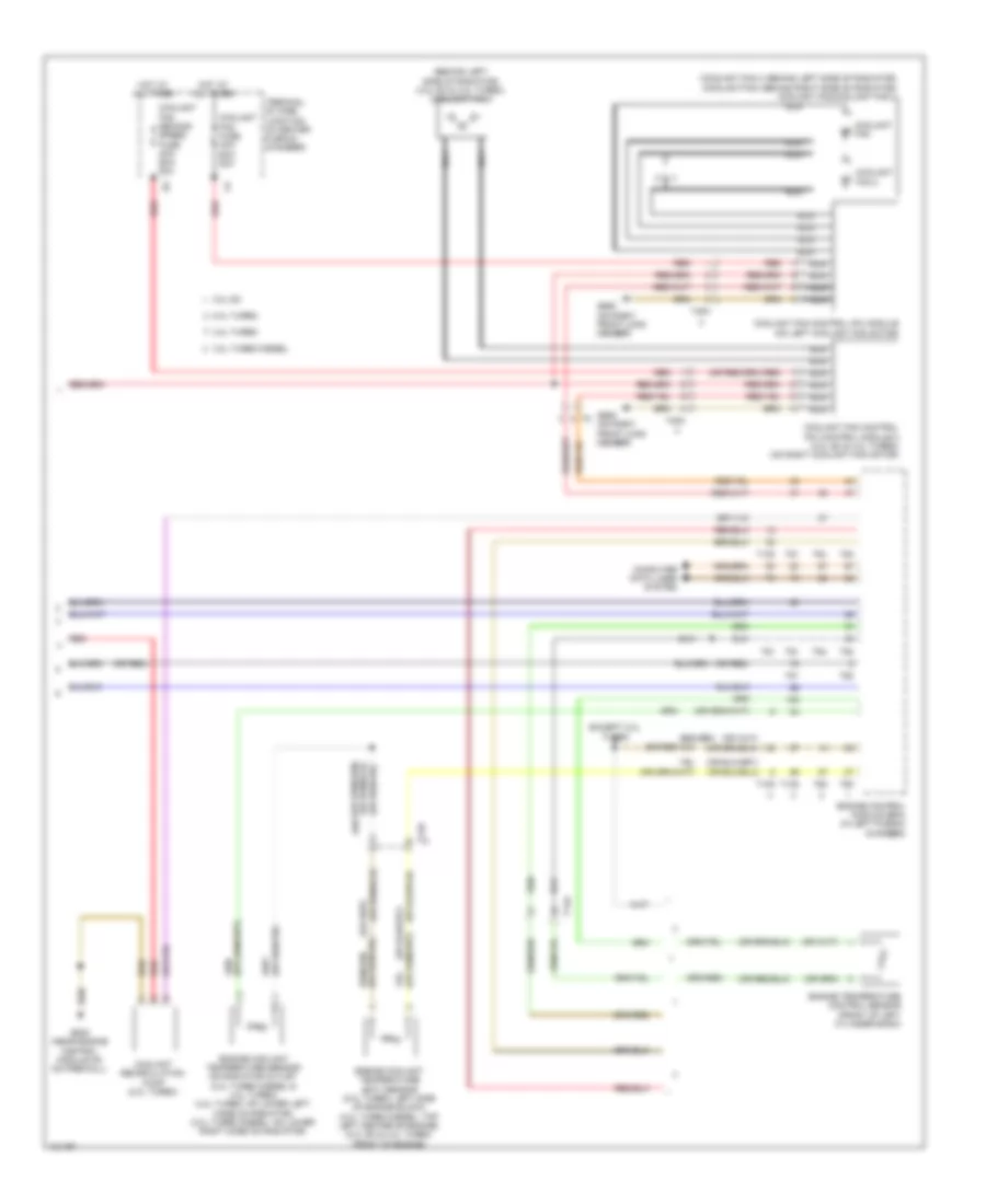
DEFOGGERS
Defoggers Wiring Diagram for Audi A6 Quattro Prestige 2014
List of elements for Defoggers Wiring Diagram for Audi A6 Quattro Prestige 2014:
- Climatronic control module
- Comfort system central control module (right side of luggage compt)
- Computer data lines system
- Driver's door control module (in driver's door)
- Driver's side outside folding mirror
- Fm frequency filter in positive wire
- Front passenger's door control module (in front passenger's door)
- Front passenger's side outside folding mirror
- Fuse 30a
- Fuse 40a
- Fuse carrier
- Fuse carrier 1
- Fuse carrier 5
- G34 (under driver's seat)
- G35 (under front passenger's seat)
- G51 (right side of luggage compt)
- G659
- Heated driver exterior rearview mirror
- Heated front passenger's exterior rearview mirror
- Hot at all times
- Mirrors system
- Rear window defogger
- Rear window defogger relay (on relay & fuse panel f)
- Relay & fuse panel b (left end of dash)
- Relay & fuse panel f (right rear of luggage compt)
- T16l
- T16m
- T20c
- T20e
- T20f
- T23a
- T23b
- T32i
- Windshield antenna suppression filter
ELECTRONIC POWER STEERING
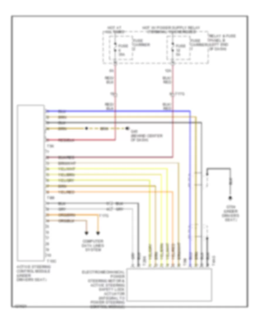
Active Steering Control Module Wiring Diagram for Audi A6 Quattro Prestige 2014
List of elements for Active Steering Control Module Wiring Diagram for Audi A6 Quattro Prestige 2014:
- 12a
- Active steering control module (under driver's seat)
- Computer data lines system
- Electro-mechanical power steering motor & active steering safety lock actuator (integral to power steering control module)
- Fuse 35a
- Fuse 5a
- Fuse carrier
- G45 (behind center of dash)
- G704 (under driver's seat)
- Hot at all times
- Relay & fuse panel b (left end of dash)
- T10c
- T17g
- T2bk
- T4ag
- T5k
- T6m
- T8m
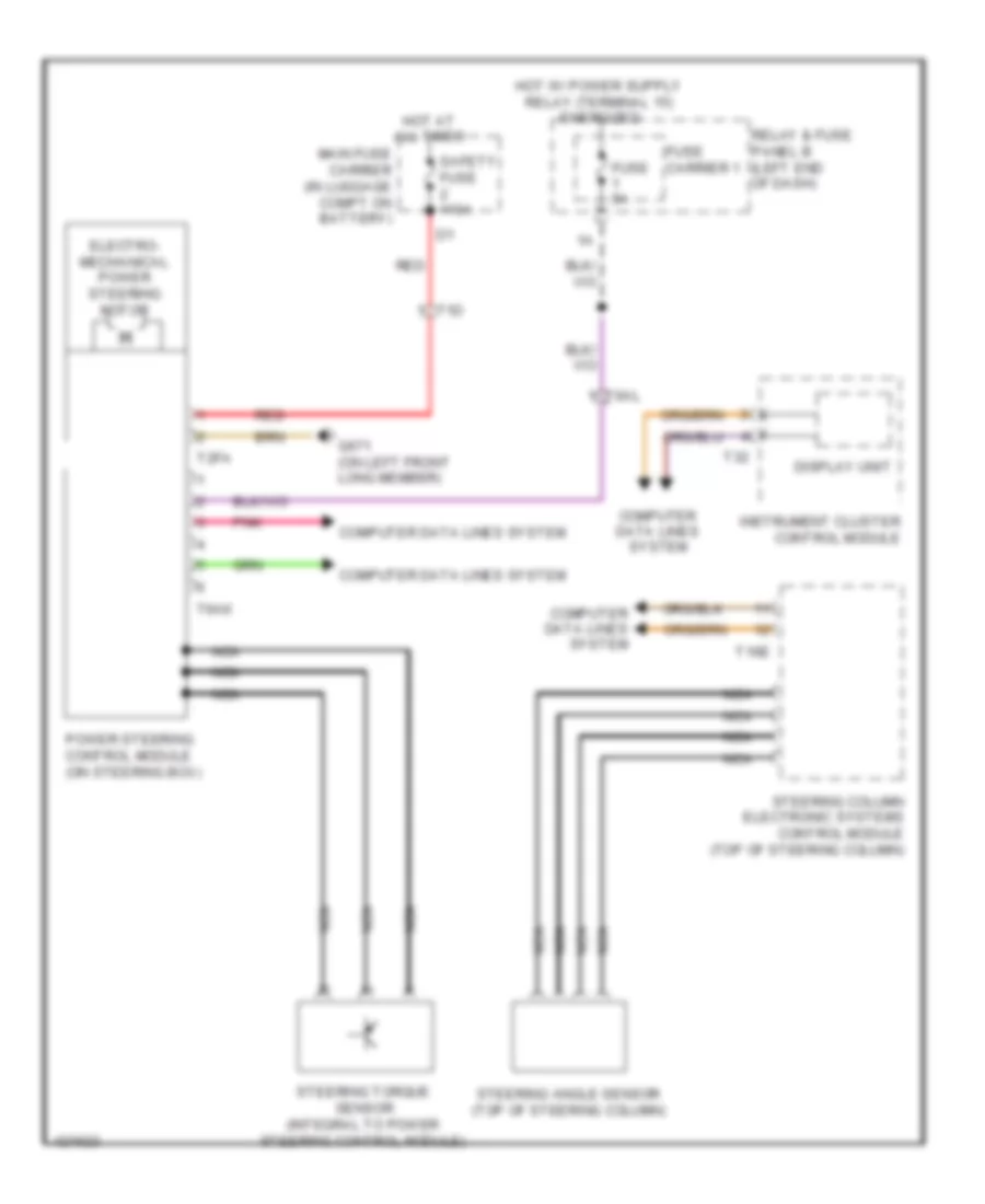
Electromechanical Power Steering Wiring Diagram for Audi A6 Quattro Prestige 2014
List of elements for Electromechanical Power Steering Wiring Diagram for Audi A6 Quattro Prestige 2014:
- Computer data lines system
- Display unit
- Electro- mechanical power steering motor
- Fuse 5a
- Fuse carrier 1
- G671 (on left front long member)
- Hot at all times
- Instrument cluster control module
- Main fuse carrier (in luggage compt on battery)
- Nca
- Pnk
- Power steering control module (on steering box)
- Red
- Relay & fuse panel b (left end of dash)
- Safety fuse 110a
- Steering angle sensor (top of steering column)
- Steering column electronic systems control module (top of steering column)
- Steering torque sensor (integral to power steering control module)
- T16e
- T1d
- T2fa
- T32
- T6ak
- T6al
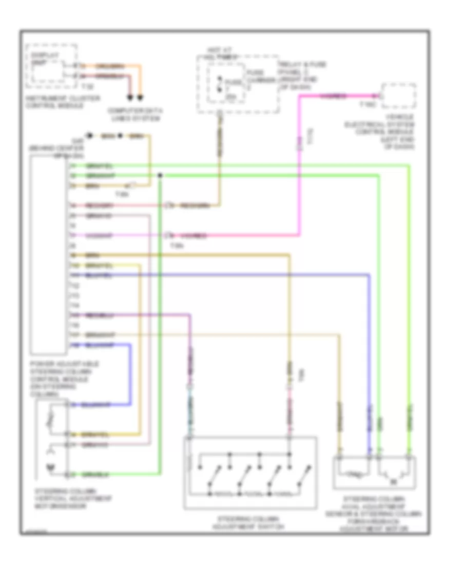
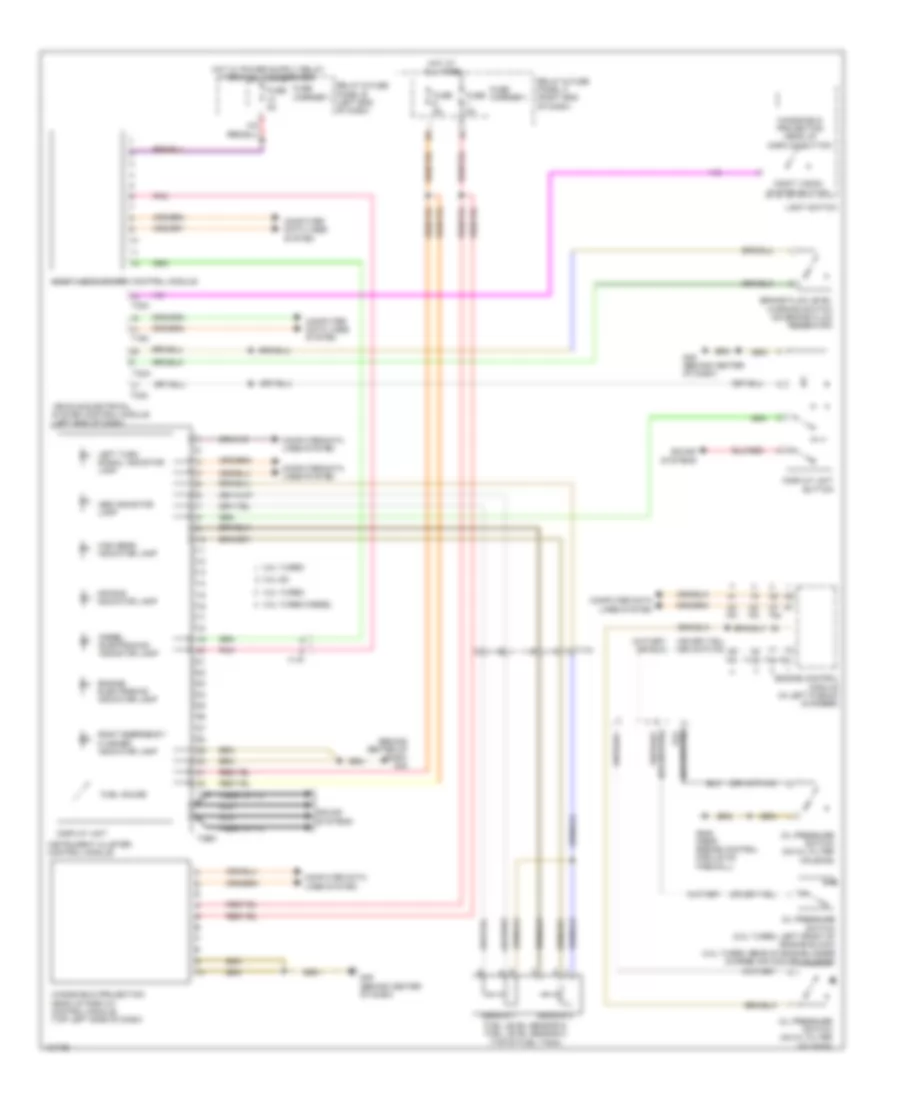
Power Steering Column Wiring Diagram for Audi A6 Quattro Prestige 2014
List of elements for Power Steering Column Wiring Diagram for Audi A6 Quattro Prestige 2014:
- Computer data lines system
- Display unit
- Fuse 25a
- Fuse carrier
- G45 (behind center of dash)
- Hot at all times
- Instrument cluster control module
- Power adjustable steering column control module (on steering column)
- Relay & fuse panel c (right end of dash)
- Steering column adjustment switch
- Steering column axial adjustment sensor & steering column forward/back adjustment motor
- Steering column vertical adjustment motor/sensor
- T16c
- T17g
- T32
- T6n
- Vehicle electrical system control module (left end of dash)
ELECTRONIC SUSPENSION
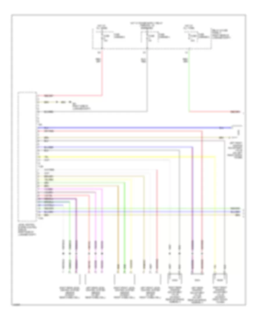
Electronic Suspension Wiring Diagram (1 of 2) for Audi A6 Quattro Prestige 2014
List of elements for Electronic Suspension Wiring Diagram (1 of 2) for Audi A6 Quattro Prestige 2014:
- Carrier 2
- Carrier 4
- Carrier 5
- Energized
- Fuse
- Fuse 15a
- Fuse 40a
- Fuse 5a
- G51 (right side of luggage compt)
- Hot at all times
- Left front damping adjustment valve (on left front shock tower)
- Left front level control system sensor (in left front wheelwell)
- Left rear damping adjustment valve (on left rear air spring assembly)
- Left rear level control system sensor (in left rear wheelwell)
- Level control system control module (right side of luggage compt)
- Relay & fuse panel f (right rear of luggage compt)
- Right front damping adjustment valve (on right front shock tower)
- Right front level control system sensor (in right front wheelwell)
- Right rear damping adjustment valve (on right rear air spring assembly)
- Right rear level control system sensor (in right rear wheelwell)
- T12r
- T15a
- T9a
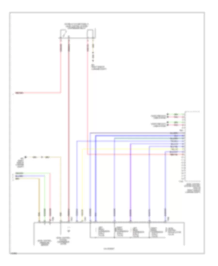
Electronic Suspension Wiring Diagram (2 of 2) for Audi A6 Quattro Prestige 2014
List of elements for Electronic Suspension Wiring Diagram (2 of 2) for Audi A6 Quattro Prestige 2014:
- (on relay & fuse panel f) level control system compressor relay
- Computer data lines system
- G51 (right side of luggage compt)
- Left front suspension strut valve
- Left rear suspension strut valve
- Level control accumulator valve
- Level control pressure sensor
- Level control system compressor motor
- Level control system control module (right side of luggage compt)
- Pnk
- Right front suspension strut valve
- Right rear suspension strut valve
- T10h
- T18a
- T2cz
- T4ay
- T6w
- Valve body
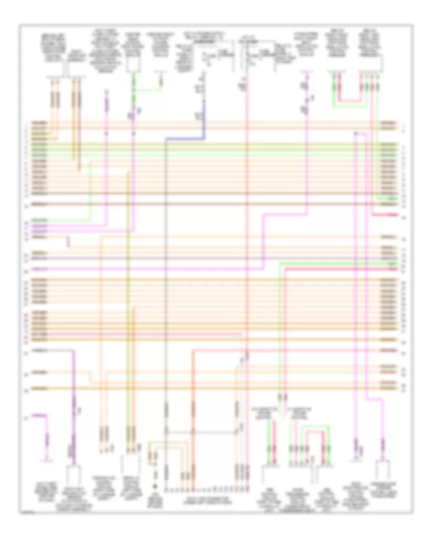
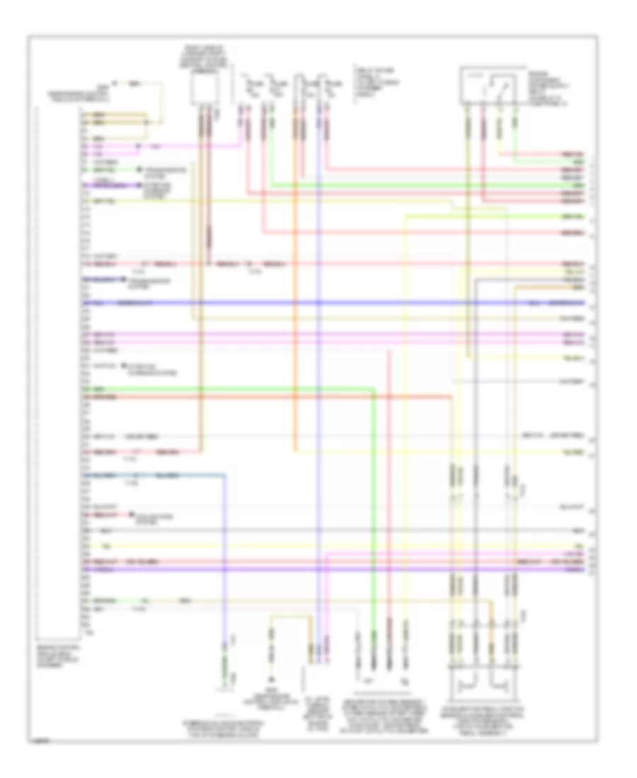
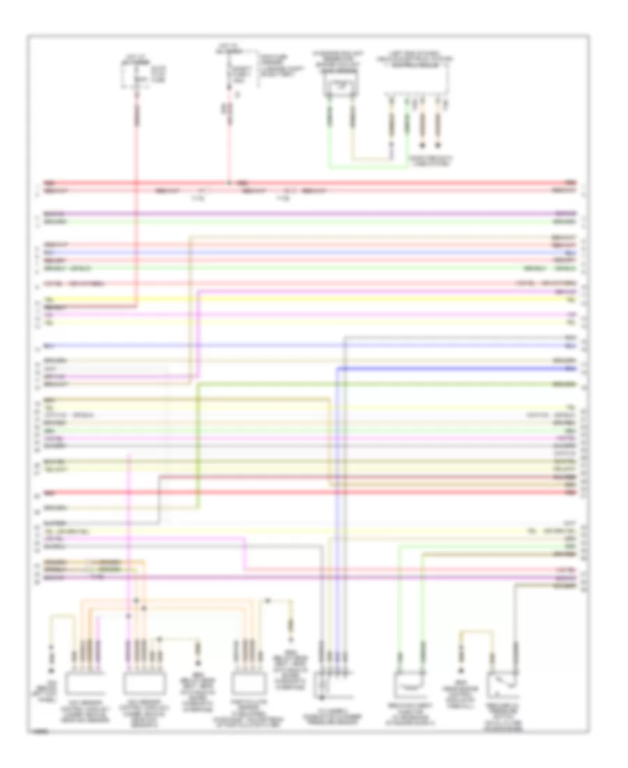
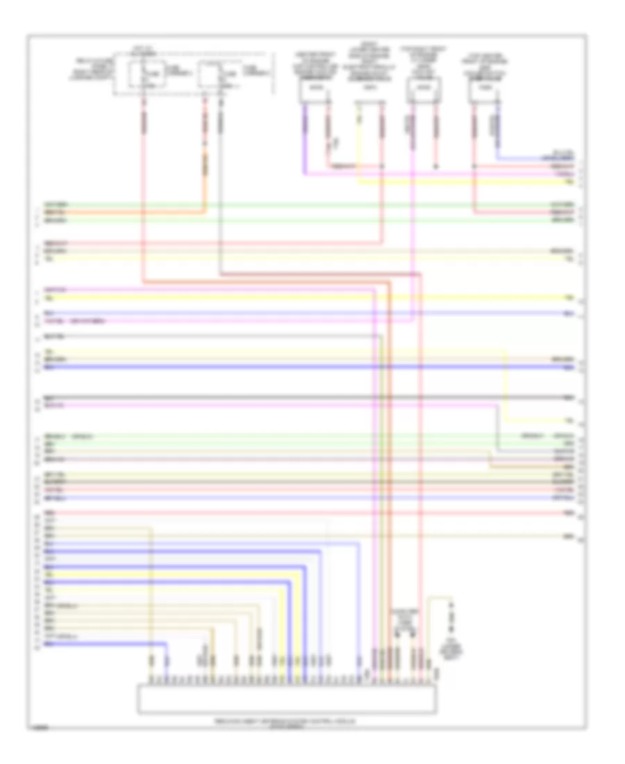
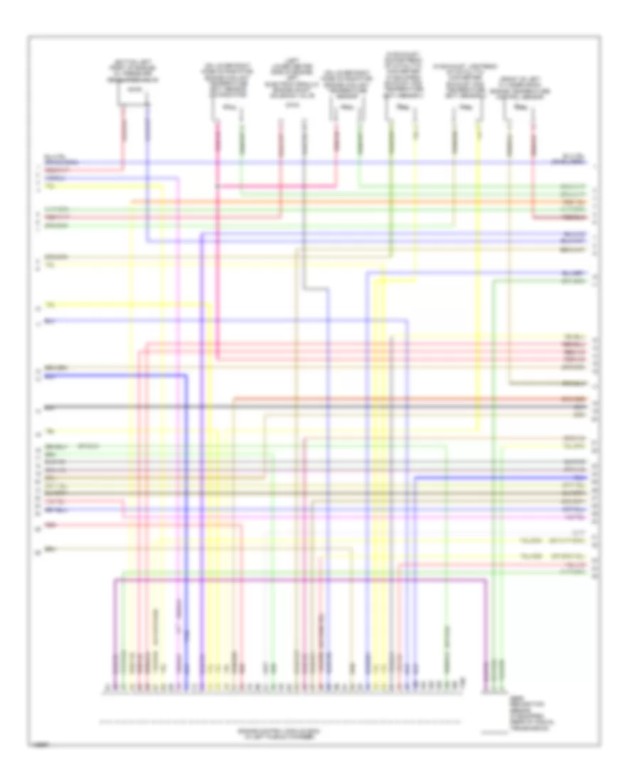
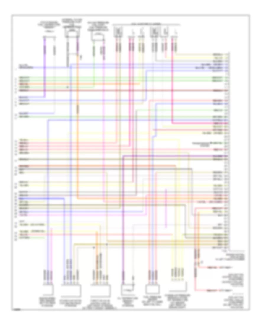
ENGINE PERFORMANCE
2.0L TURBO
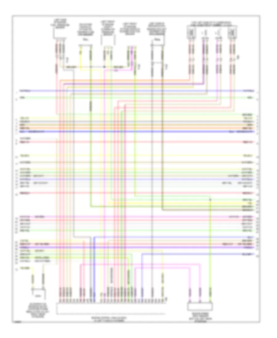
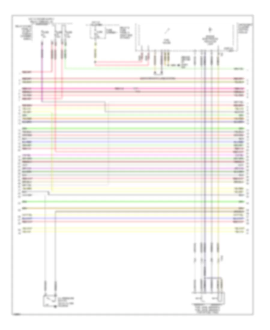
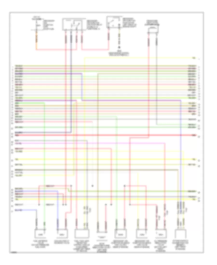
2.0L Turbo, Engine Performance Wiring Diagram (1 of 6) for Audi A6 Quattro Prestige 2014
List of elements for 2.0L Turbo, Engine Performance Wiring Diagram (1 of 6) for Audi A6 Quattro Prestige 2014:
- (right side of luggage compt) comfort system central control module
- 14a
- Accelerator pedal position sensor & accelerator pedal position sensor 2 (top of accelerator pedal assembly)
- Cooling fans system
- Engine control module (ecm) (in left plenum chamber)
- Fuse 15a
- Fuse 20a
- Fuse 5a
- G645 (near engine control module on firewall)
- Heater for oxygen sensor 1 after catalytic converter & oxygen sensor after three way catalytic converter (in exhaust, downstream of 3-way catalytic converter)
- Nca
- Oil level thermal sensor (bottom of engine oil pan)
- Relay & fuse panel a (in left plenum chamber e-box)
- Starting/ charging system
- Steering column electronic systems control module (top of steering column)
- System
- T16e
- T17a
- T17b
- T17h
- T17i
- T17o
- T32g
- T94
- Transmissions
- Transmissions system
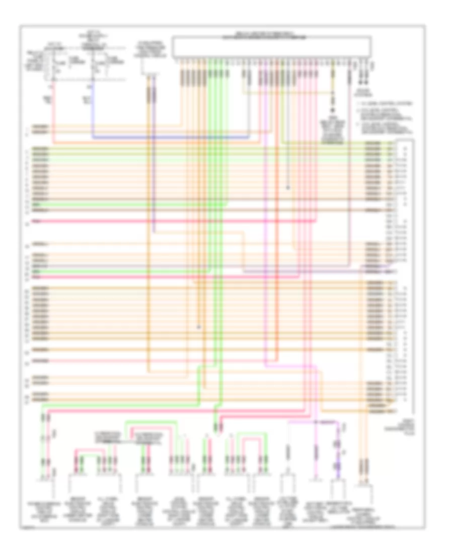
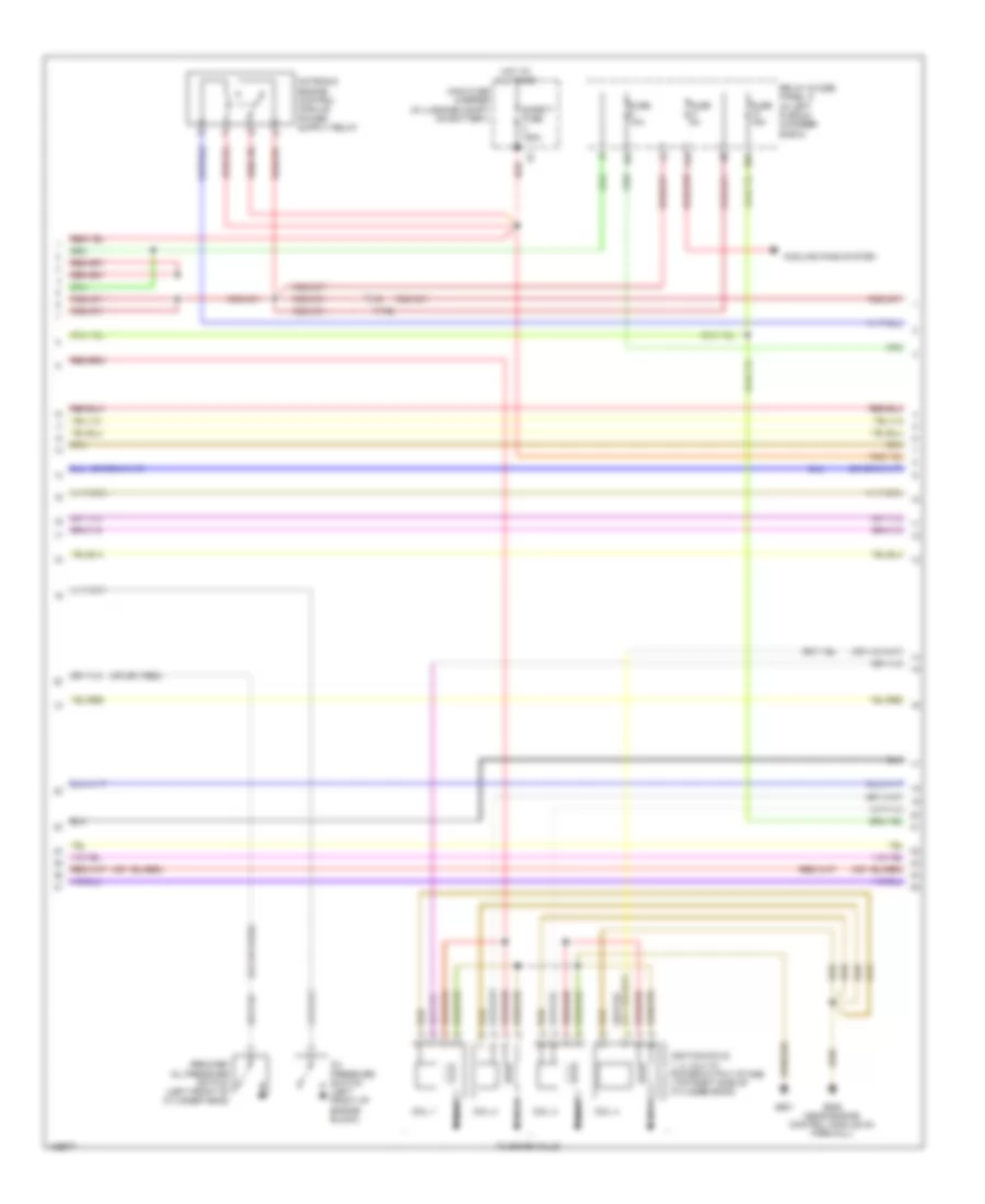
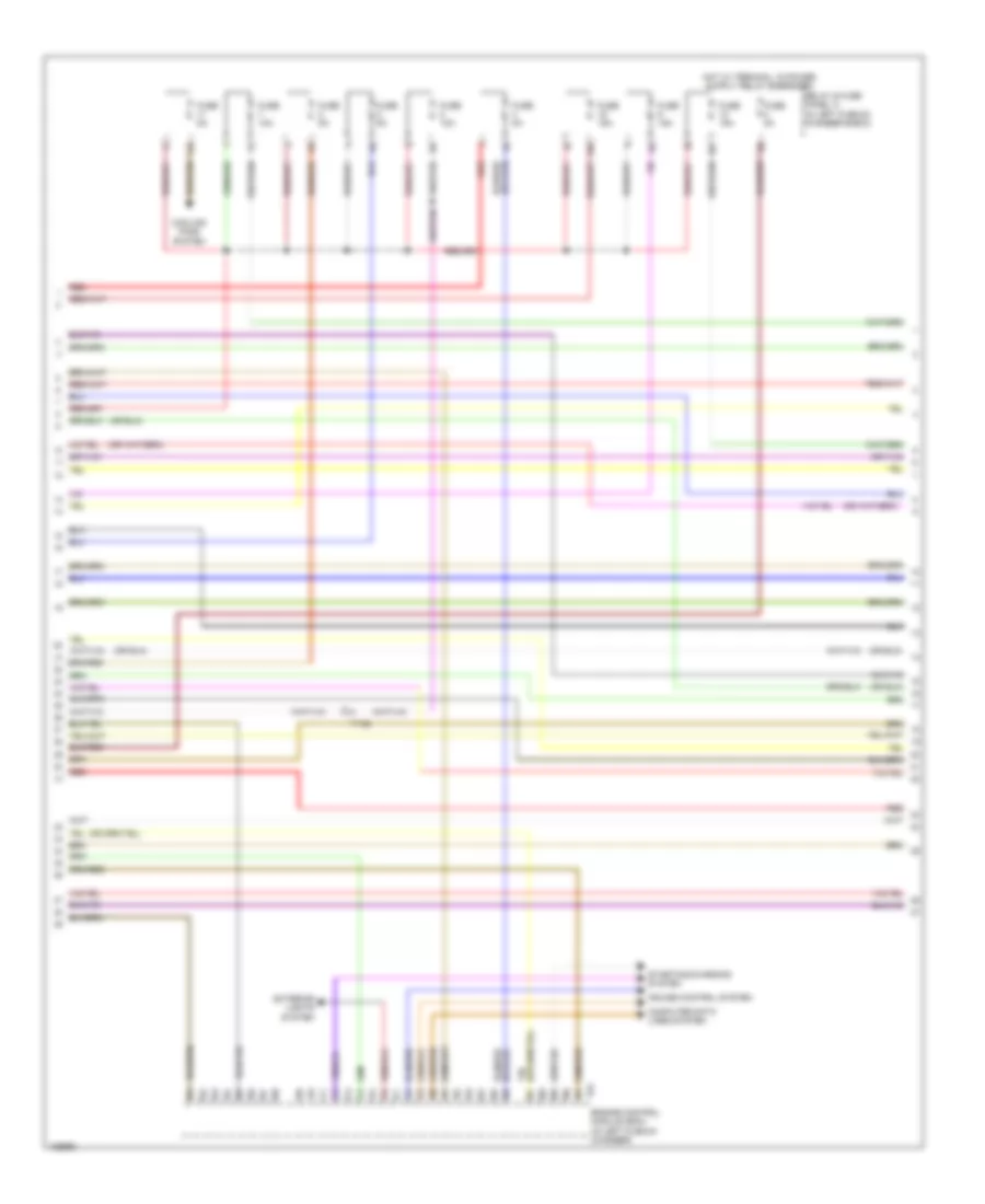
2.0L Turbo, Engine Performance Wiring Diagram (2 of 6) for Audi A6 Quattro Prestige 2014
List of elements for 2.0L Turbo, Engine Performance Wiring Diagram (2 of 6) for Audi A6 Quattro Prestige 2014:
- 10a
- 11a
- Coil 1
- Coil 2
- Coil 3
- Coil 4
- Cooling fans system
- Fuse 10a
- Fuse 15a
- Fuse 5a
- G601
- G645 (near engine control module on firewall)
- Hot at all times
- Ignition coils 1, 2, 3 & 4 w/ power output stage (top right side of cylinder bank)
- Main fuse carrier (in luggage compt on battery)
- Nca
- Oil pressure switch (left front of engine block)
- Red
- Reduced oil pressure switch (left front of cylinder head)
- Relay & fuse panel a (in left plenum chamber e-box)
- Safety fuse 150a
- T17b
- To spark plug
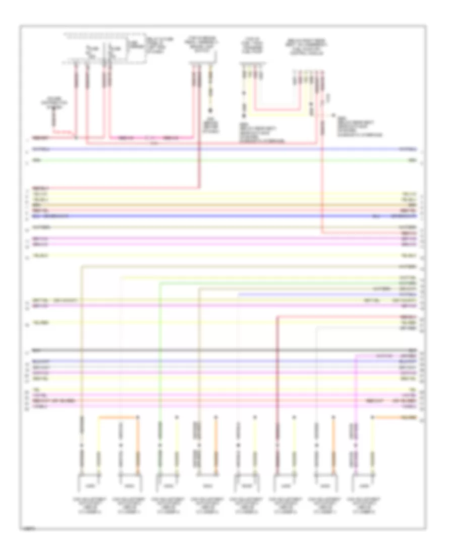
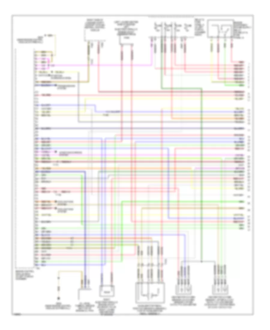
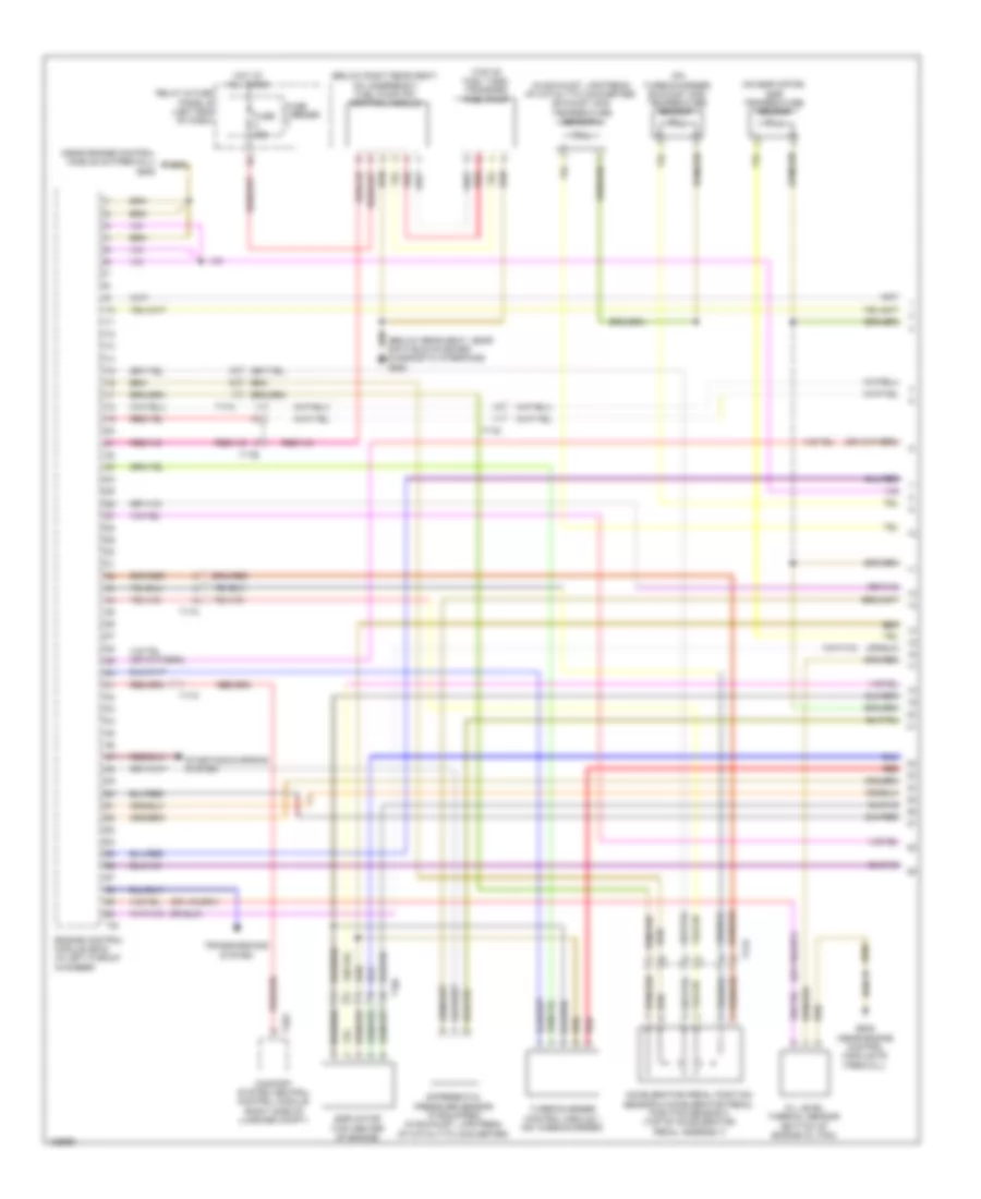
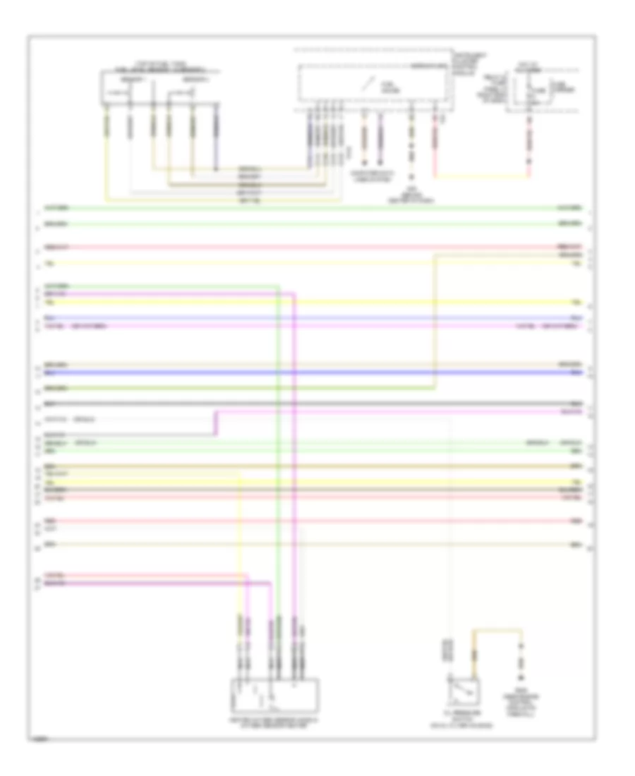
2.0L Turbo, Engine Performance Wiring Diagram (3 of 6) for Audi A6 Quattro Prestige 2014
List of elements for 2.0L Turbo, Engine Performance Wiring Diagram (3 of 6) for Audi A6 Quattro Prestige 2014:
- (below right rear seat, on underbody) fuel pump (fp) control module
- (or red)
- (top of brake pedal assembly) brake lamp switch
- (top of fuel tank) transfer fuel pump
- Cam adjustment actuator 1 (above cylinder 1)
- Cam adjustment actuator 2 (above cylinder 1)
- Cam adjustment actuator 3 (above cylinder 2)
- Cam adjustment actuator 4 (above cylinder 2)
- Cam adjustment actuator 5 (above cylinder 3)
- Cam adjustment actuator 6 (above cylinder 3)
- Cam adjustment actuator 7 (above cylinder 4)
- Cam adjustment actuator 8 (above cylinder 4)
- Fuse 25a
- Fuse 5a
- Fuse carrier
- G45 (behind center of dash)
- G688 (below rear seat, near data bus on board diagnostic interface)
- Power distribution system
- Red
- Relay & fuse panel b (left end of dash)
- T17b
- T17i
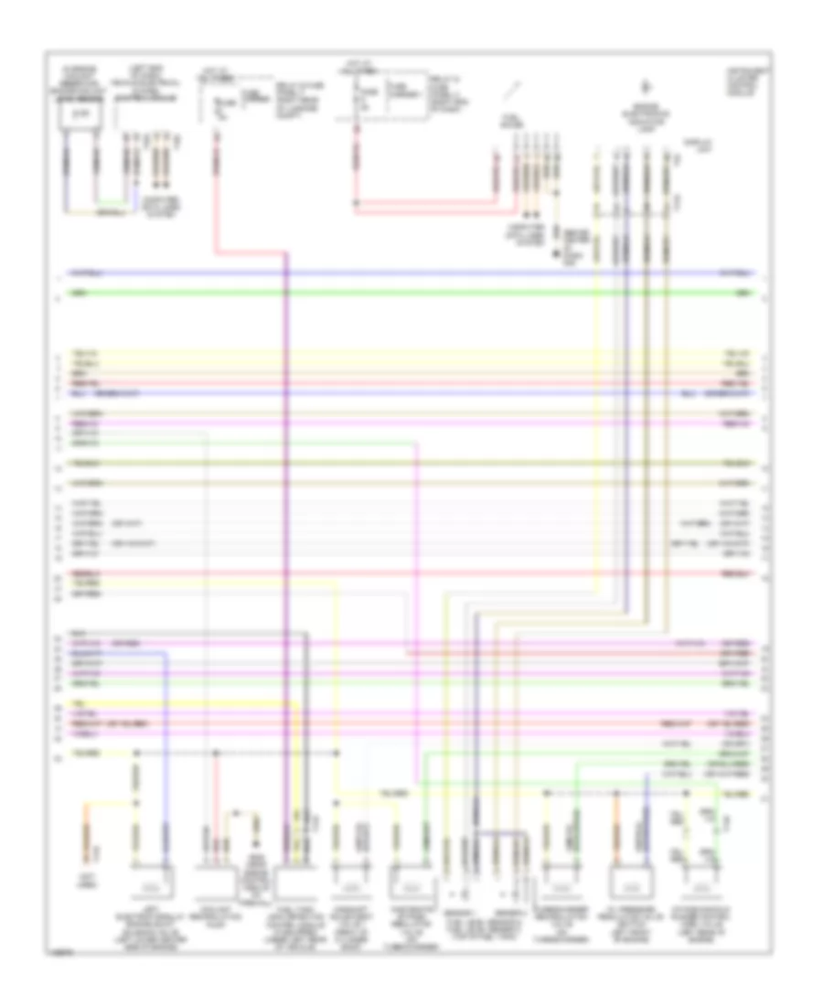
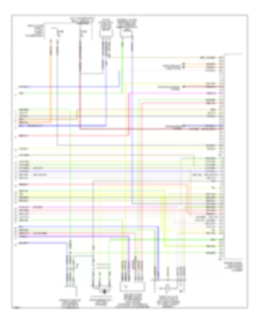
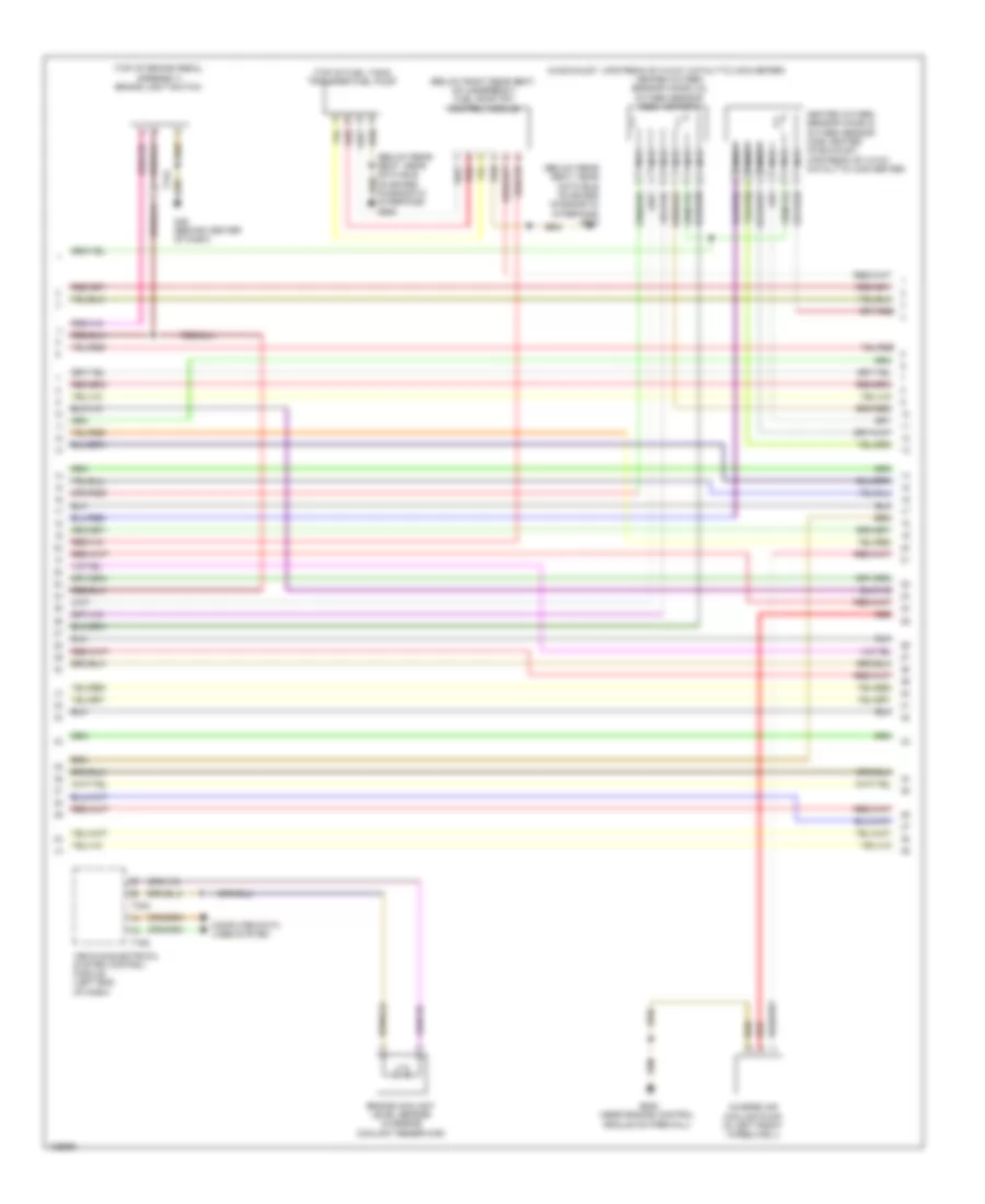
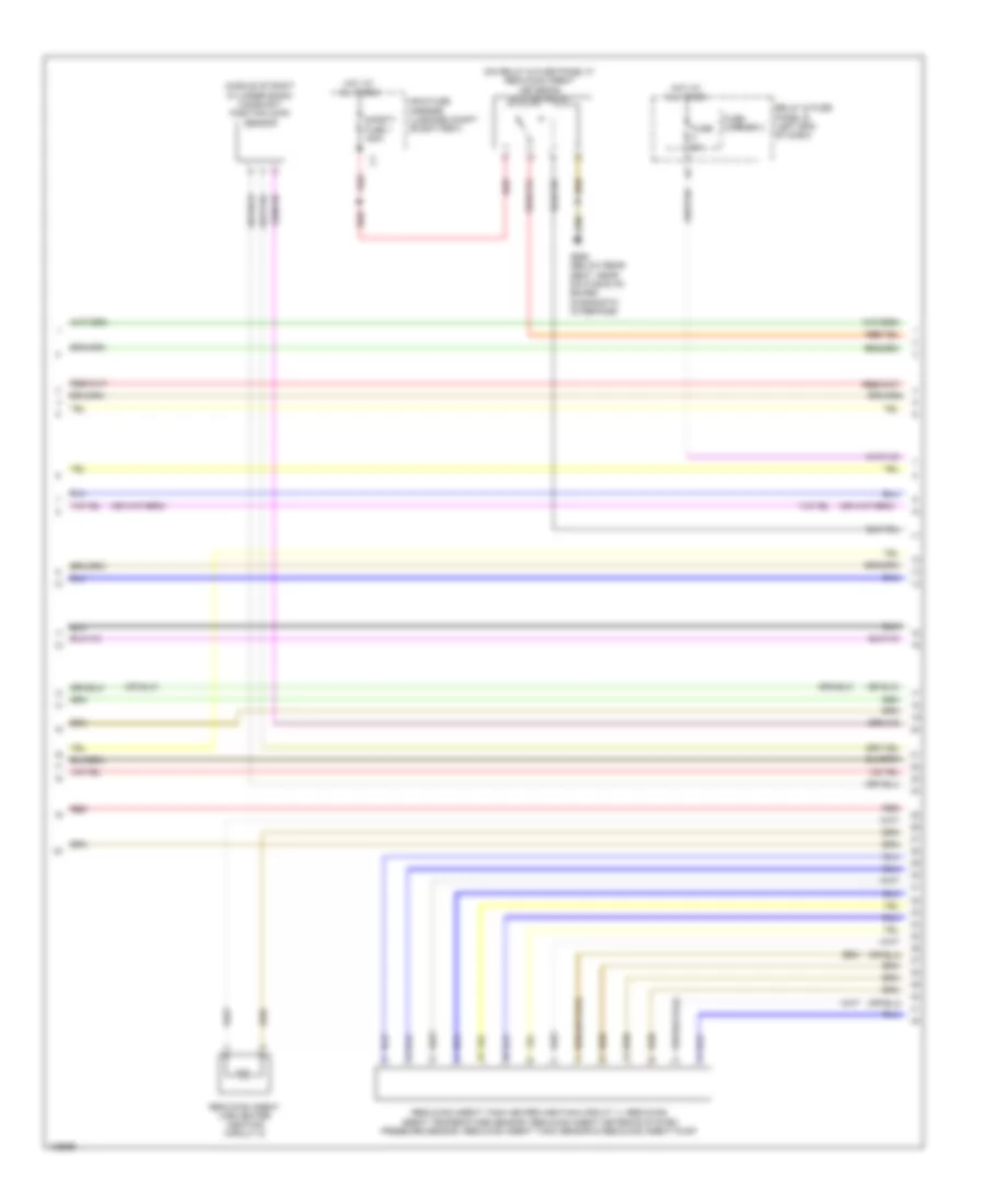
2.0L Turbo, Engine Performance Wiring Diagram (4 of 6) for Audi A6 Quattro Prestige 2014
List of elements for 2.0L Turbo, Engine Performance Wiring Diagram (4 of 6) for Audi A6 Quattro Prestige 2014:
- (behind center of dash) g45
- (in engine coolant reservoir) engine coolant level sensor
- (left end of dash) vehicle electrical system control module
- (not used)
- (or red)
- Camshaft adjustment valve 1 (front of cylinder bank)
- Computer data lines system
- Coolant recirculation pump
- Display unit
- Engine electronics indicator lamp
- Fuel gauge
- Fuel level sensor & fuel level sensor 2 (top of fuel tank)
- Fuel tank leak detection control module (if equipped) (under left rear of vehicle)
- Fuse 5a
- Fuse carrier
- Fuse carrier 1
- G645 (near engine control module on firewall)
- Hot at all times
- Instrument cluster control module
- Intake manifold runner control (imrc) valve (left rear of engine)
- Left electrohydraulic engine mount solenoid valve (left lower center side of engine)
- Oil pressure regulation valve (bottom left front of engine)
- Red
- Relay & fuse panel c (right end of dash)
- Relay & fuse panel f (right rear of luggage compt)
- Sensor 1
- Sensor 2
- T14b
- T16c
- T17b
- T17h
- T32
- T32a
- Turbocharger recirculation valve (on turbocharger)
- Wastegate bypass regulator valve (on turbocharger)
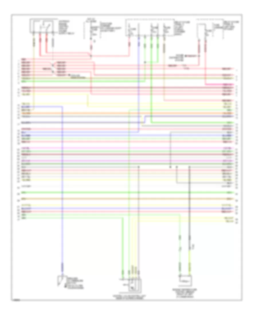
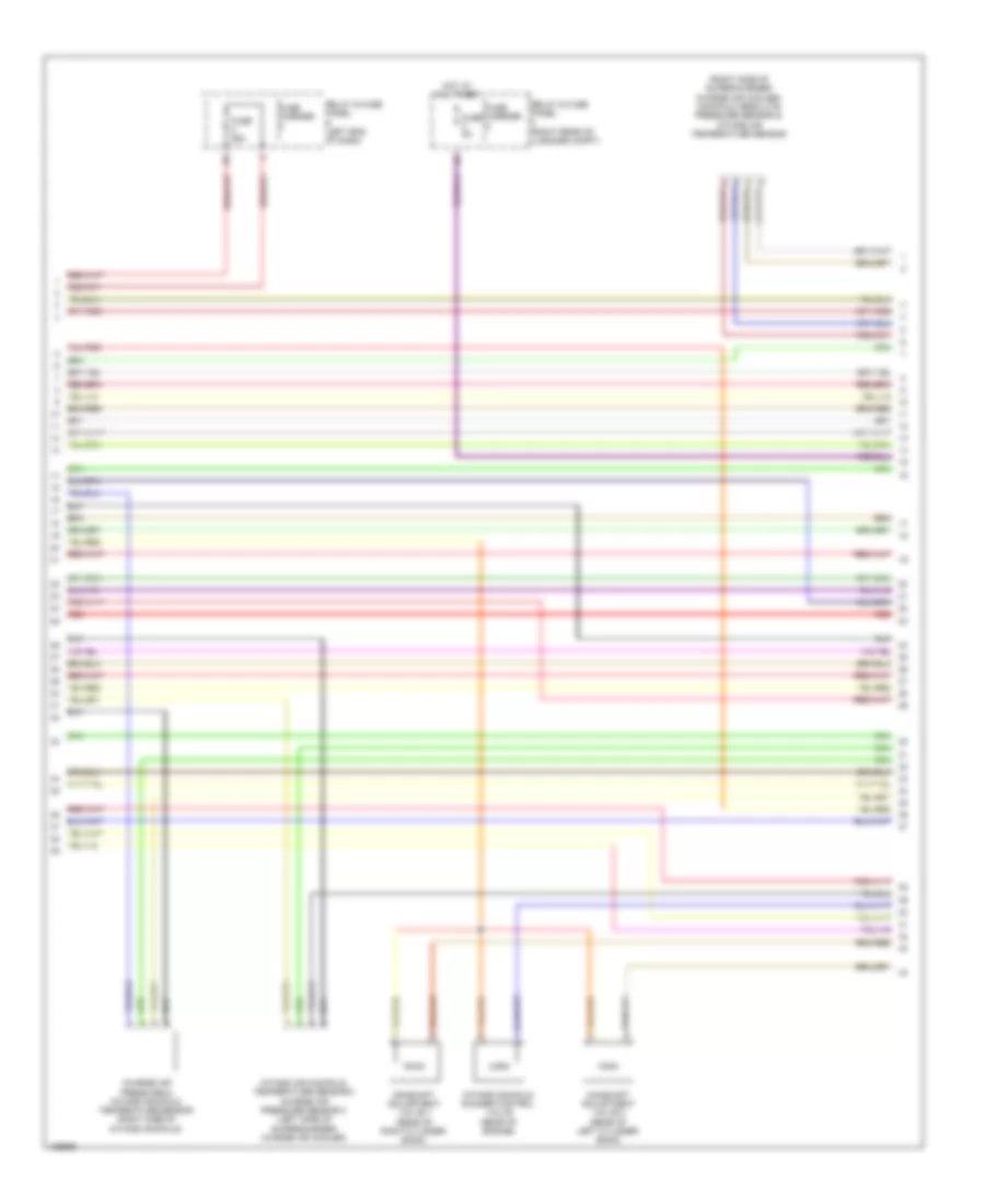
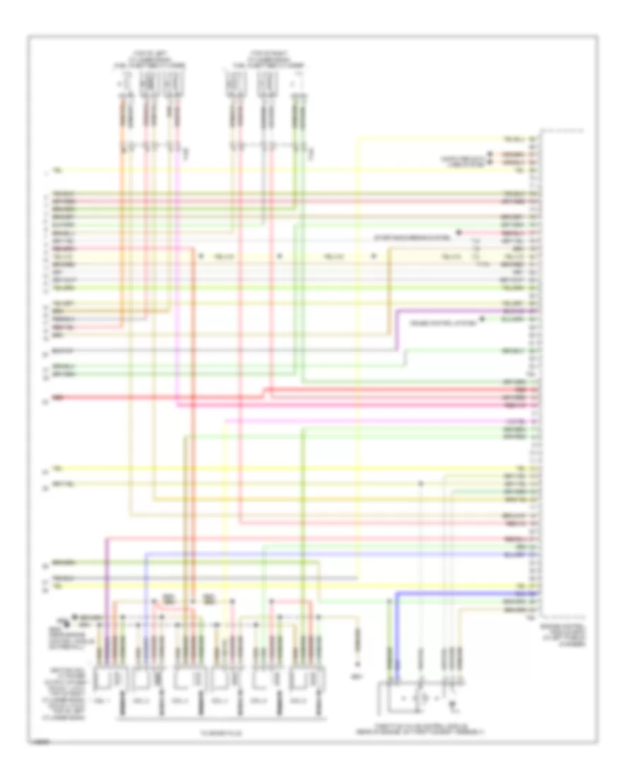
2.0L Turbo, Engine Performance Wiring Diagram (5 of 6) for Audi A6 Quattro Prestige 2014
List of elements for 2.0L Turbo, Engine Performance Wiring Diagram (5 of 6) for Audi A6 Quattro Prestige 2014:
- (left front of engine compt) charge air pressure sensor
- (left front of engine) intake manifold runner position sensor
- (left side of engine block)
- (left side of engine) fuel pressure sensor
- (on intake manifold) intake air temperature (iat) sensor
- (or red)
- (top left side of cylinder bank) fuel injector cylinders 1, 2, 3 & 4
- Engine control module (ecm) (in left plenum chamber)
- Engine coolant temperature (ect) sensor
- Engine speed (rpm) sensor (bottom left rear of engine)
- Evaporative emission (evap) canister purge regulator valve 1 (right rear of engine)
- T14b
- T60
- T8s
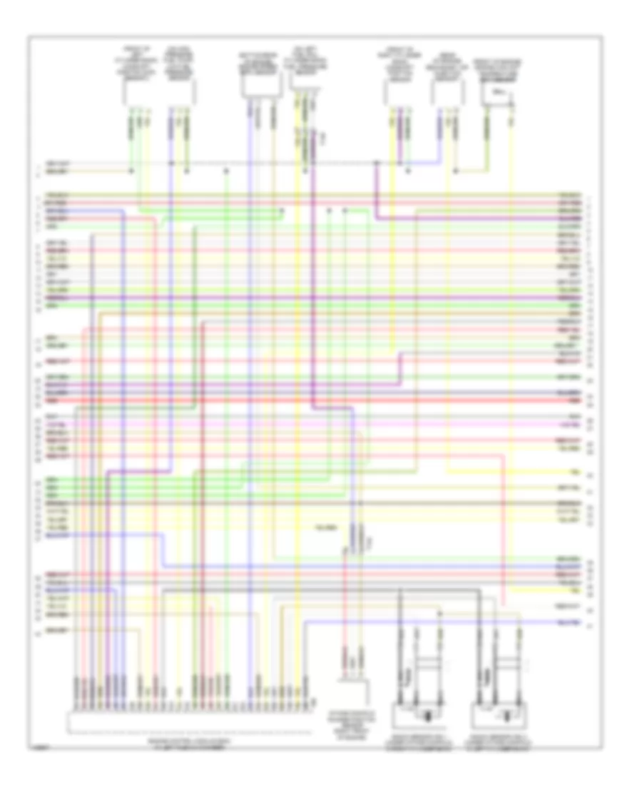
2.0L Turbo, Engine Performance Wiring Diagram (6 of 6) for Audi A6 Quattro Prestige 2014
List of elements for 2.0L Turbo, Engine Performance Wiring Diagram (6 of 6) for Audi A6 Quattro Prestige 2014:
- (integral to high pressure pump) fuel pressure regulator valve
- (on air intake duct) mass air flow (maf) sensor
- (or red)
- Camshaft position (cmp) sensor (top center of cylinder bank)
- Computer data lines system
- Engine control module (ecm) (in left plenum chamber)
- Fuse 5a
- Heated oxygen sensor (ho2s) & oxygen sensor (o2s) heater (in exhaust, upstream of 3-way catalytic converter)
- Knock sensor (ks) 1 (left side of engine)
- Nca
- Relay & fuse panel a (in left plenum chamber e-box)
- Starting/charging system
- T14b
- T60
- T94
- Throttle valve control module (left side of engine, on throttle body assembly)
- Transmissions system
3.0L SC
3.0L SC, Engine Performance Wiring Diagram (1 of 8) for Audi A6 Quattro Prestige 2014
List of elements for 3.0L SC, Engine Performance Wiring Diagram (1 of 8) for Audi A6 Quattro Prestige 2014:
- (left lower center side of engine) left electrohydraulic engine mount solenoid valve
- (right side of luggage compt) comfort system central control module
- 17a
- Accelerator pedal position sensor & sensor 2 (top of accelerator pedal assembly)
- Cooling fans system
- Engine control module (ecm) (in left plenum chamber)
- Fuse 15a
- Fuse 5a
- G645 (near engine control module on firewall)
- Heater for oxygen sensor 1 after & 3 way catalytic converter (in exhaust, downstream of 3-way catalytic)
- Heater for oxygen sensor 2 & oxygen sensor 2 after catalytic converter
- Nca
- Oil level thermal sensor (bottom of engine oil pan)
- Red
- Relay & fuse panel a (in left plenum chamber e-box)
- Right electrohydraulic engine mount solenoid valve (right lower center side of engine)
- Starting/ charging system
- Starting/charging system
- T14b
- T17a
- T17b
- T17h
- T32g
- T94
- Transmissions system
3.0L SC, Engine Performance Wiring Diagram (2 of 8) for Audi A6 Quattro Prestige 2014
List of elements for 3.0L SC, Engine Performance Wiring Diagram (2 of 8) for Audi A6 Quattro Prestige 2014:
- 14a
- Control valve control unit (rear of supercharger)
- Cooling fans system
- Engine temperature control sensor (front of left cylinder bank)
- Fuse 10a
- Fuse 20a
- Fuse 5a
- Fuse carrier
- Hot at all times
- Main fuse carrier (in luggage compt on battery)
- Power distribution system
- Red
- Reduced oil pressure switch (on oil filter housing base)
- Relay & fuse panel a (in left plenum chamber e-box)
- Relay & fuse panel b (left end of dash)
- Safety fuse 150a
- T14a
- T17b
3.0L SC, Engine Performance Wiring Diagram (3 of 8) for Audi A6 Quattro Prestige 2014
List of elements for 3.0L SC, Engine Performance Wiring Diagram (3 of 8) for Audi A6 Quattro Prestige 2014:
- (behind center of dash) g45
- 10a
- 16a
- Computer data lines system
- Display unit
- Engine electronics indicator lamp
- Fuel gauge
- Fuel level sensor & fuel level sensor 2 (top of fuel tank)
- Fuse 15a
- Fuse 5a
- Fuse carrier 1
- Hot at all times
- Instrument cluster control module
- Oil pressure switch (on oil filter housing)
- Relay & fuse panel a (in left plenum chamber e-box)
- Relay & fuse panel c (right end of dash)
- Sensor 1
- Sensor 2
- T17h
- T17i
- T32
3.0L SC, Engine Performance Wiring Diagram (4 of 8) for Audi A6 Quattro Prestige 2014
List of elements for 3.0L SC, Engine Performance Wiring Diagram (4 of 8) for Audi A6 Quattro Prestige 2014:
- (below rear seat, near data bus on board diagnostic interface) g688
- (below right rear seat, on underbody) fuel pump (fp) control module
- (in exhaust, upstream of 3-way catalytic converter) heated oxygen sensor (ho2s) 2 & oxygen sensor (o2s) heater 2
- (top of brake pedal assembly) brake light switch
- (top of fuel tank) transfer fuel pump
- Charge air cooling pump (in left front wheelwell)
- Computer data lines system
- Engine coolant level sensor (in engine coolant reservoir)
- G45 (behind center of dash)
- G645 (near engine control module on firewall)
- Heated oxygen sensor (ho2s) & oxygen sensor (o2s) heater (in exhaust, upstream of 3-way catalytic converter)
- Nca
- Red
- T16c
- T17o
- T32a
- Vehicle electrical system control module (left end of dash)
3.0L SC, Engine Performance Wiring Diagram (5 of 8) for Audi A6 Quattro Prestige 2014
List of elements for 3.0L SC, Engine Performance Wiring Diagram (5 of 8) for Audi A6 Quattro Prestige 2014:
- (right side of supercharger charge air cooler) manifold absolute pressure sensor & intake air temperature sensor
- Camshaft adjustment valve 1 (rear of right cylinder bank)
- Camshaft adjustment valve 2 (rear of left cylinder bank)
- Charge air pressure & intake manifold temperature sensor (right side of intake manifold)
- Fuse 25a
- Fuse 5a
- Fuse carrier
- Hot at all times
- Intake air manifold temperature sensor 2 charge air pressure sensor 2 (left side of supercharger charge air cooler)
- Intake manifold runner control valve (rear of engine)
- Red
- Relay & fuse panel b (left end of dash)
- Relay & fuse panel f (right rear of luggage compt)
3.0L SC, Engine Performance Wiring Diagram (6 of 8) for Audi A6 Quattro Prestige 2014
List of elements for 3.0L SC, Engine Performance Wiring Diagram (6 of 8) for Audi A6 Quattro Prestige 2014:
- (bottom rear of engine) engine speed (rpm) sensor
- (front of engine) engine coolant temperature (ect) sensor
- (front of left cylinder bank) camshaft position (cmp) sensor 2
- (front of right cylinder bank) camshaft position sensor
- (on high pressure fuel pump) low fuel pressure sensor
- (on left fuel rail cylinder bank) fuel pressure sensor
- (rear of engine) secondary air injection sensor 1
- Engine control module (ecm) (in left plenum chamber)
- Intake manifold runner position sensor (right front of engine)
- Knock sensor (ks) 1 (under intake manifold, in right cylinder bank)
- Knock sensor (ks) 2 (under intake manifold, in left cylinder bank)
- Nca
- Red
- T14a
- T14b
- T60
3.0L SC, Engine Performance Wiring Diagram (7 of 8) for Audi A6 Quattro Prestige 2014
List of elements for 3.0L SC, Engine Performance Wiring Diagram (7 of 8) for Audi A6 Quattro Prestige 2014:
- 50a
- Cooling circuit solenoid valve
- Crankcase ventilation shut-off valve
- Evap canister purge regulator valve 1 (left side of engine)
- Fuel metering valve (on high pressure fuel pump)
- Fuel tank leak detection control module (if equipped) (under left rear of vehicle)
- G645 (near engine control module on firewall)
- Hot at all times
- Intake manifold runner position sensor 2 (left front of engine)
- Oil pressure regulation valve (bottom left front of engine)
- Red
- Secondary air injection (air) pump fuse
- Secondary air injection (air) pump relay (on relay & fuse panel a)
- Secondary air injection pump motor (left front of engine compt)
- Secondary air injection solenoid (air) valve (rear of engine)
- Secondary air injection solenoid (air) valve 2 (rear of engine)
- T14a
- T14b
- T17b
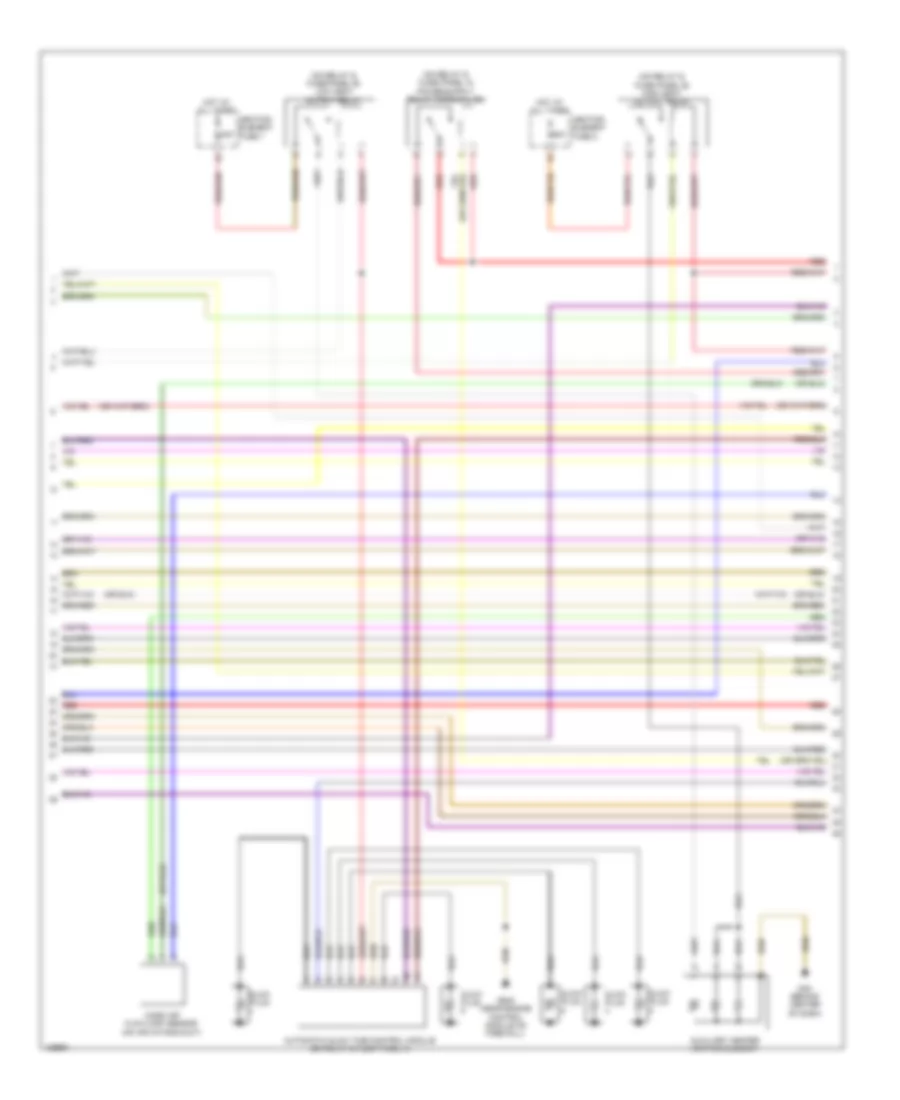
3.0L SC, Engine Performance Wiring Diagram (8 of 8) for Audi A6 Quattro Prestige 2014
List of elements for 3.0L SC, Engine Performance Wiring Diagram (8 of 8) for Audi A6 Quattro Prestige 2014:
- (top of left cylinder bank) fuel injectors cylinder
- (top of right cylinder bank) fuel injectors cylinder
- Coil 1
- Coil 2
- Coil 3
- Coil 4
- Coil 5
- Coil 6
- Computer data lines system
- Cruise control system
- Engine control module (ecm) (in left plenum chamber)
- G600
- G601
- G645 (near engine control module on firewall)
- Ignition coil w/ power output stage (coils 1, 2 & 3: top of right cylinder bank) (coils 4, 5 & 6: top of left cylinder bank)
- Nca
- Red
- Starting/charging system
- T14a
- T14b
- T17a
- T60
- T94
- Throttle valve control module (rear of engine, on throttle body assembly)
- To spark plug
3.0L TURBO DIESEL
3.0L Turbo Diesel, Engine Performance Wiring Diagram (1 of 9) for Audi A6 Quattro Prestige 2014
List of elements for 3.0L Turbo Diesel, Engine Performance Wiring Diagram (1 of 9) for Audi A6 Quattro Prestige 2014:
- (below rear seat, near data bus on board diagnostic interface) g688
- (below right rear seat, on underbody) fuel pump (fp) control module
- (in exhaust, upstream of catalytic converter) exhaust gas temperature sensor 3
- (near engine control module on firewall) g645
- (on egr motor) egr temperature sensor
- (on turbocharger) exhaust gas temperature sensor 1
- (top of fuel tank) transfer fuel pump
- Accelerator pedal position sensor & accelerator pedal position sensor 2 (top of accelerator pedal assembly)
- Comfort system central control module (right side of luggage compt)
- Differential pressure sensor (if equipped) (in exhaust, upstream of catalytic converter)
- Egr motor (top center of engine)
- Engine control module (ecm) (in left plenum chamber)
- Fuse 25a
- Fuse carrier
- G645 (near engine control module on firewall)
- Hot at all times
- Oil level thermal sensor (bottom of engine oil pan)
- Red
- Relay & fuse panel b (left end of dash)
- Starting/charging system
- T10l
- T17a
- T17b
- T17g
- T17h
- T32g
- T91
- Transmissions system
- Turbocharger control module 1 (on turbocharger)
3.0L Turbo Diesel, Engine Performance Wiring Diagram (2 of 9) for Audi A6 Quattro Prestige 2014
List of elements for 3.0L Turbo Diesel, Engine Performance Wiring Diagram (2 of 9) for Audi A6 Quattro Prestige 2014:
- (on relay & fuse panel b) high heat output relay
- (on relay & fuse panel b) low heat output relay
- 40a
- 60a
- Automatic glow time control module (on relay & fuse panel a)
- Auxiliary heater heating element
- G45 (behind center of dash)
- G645 (near engine control module on firewall)
- Glow plug
- Heating element fuse 1
- Heating element fuse 2
- Hot at all times
- Mass air flow (maf) sensor (on air intake duct)
- Red
3.0L Turbo Diesel, Engine Performance Wiring Diagram (3 of 9) for Audi A6 Quattro Prestige 2014
List of elements for 3.0L Turbo Diesel, Engine Performance Wiring Diagram (3 of 9) for Audi A6 Quattro Prestige 2014:
- (in engine coolant reservoir) engine coolant level sensor
- (left end of dash) vehicle electrical system control module
- 80a
- Computer data lines system
- Cylinder 2 combustion chamber pressure sensor
- G44 (behind left kick panel)
- G645 (near engine control module on firewall)
- G688 (below rear seat, near data bus on board diagnostic interface)
- Glow plug fuse
- Hot at all times
- Injector (w/ emissions standard euro 4)
- Main fuse carrier (luggage compt on battery)
- Nox sensor control module 1 (under vehicle, near nox sensor)
- Nox sensor control module 2 (under vehicle, near nox sensor 2)
- Particulate sensor (if equipped) (in exhaust, downstream of particulate filter)
- Red
- Reduced oil pressure switch (on oil filter housing base)
- Reducing agent
- Safety fuse 3 150a
- T16c
- T17b
- T17g
- T32a
3.0L Turbo Diesel, Engine Performance Wiring Diagram (4 of 9) for Audi A6 Quattro Prestige 2014
List of elements for 3.0L Turbo Diesel, Engine Performance Wiring Diagram (4 of 9) for Audi A6 Quattro Prestige 2014:
- 10a
- 11a
- 16a
- Computer data lines system
- Cooling fans system
- Cruise control system
- Engine control module (ecm) (in left plenum chamber)
- Exterior lights system
- Fuse 10a
- Fuse 15a
- Fuse 5a
- Red
- Relay & fuse panel a (in left plenum chamber e-box)
- Starting/charging system
- T17b
- T91
3.0L Turbo Diesel, Engine Performance Wiring Diagram (5 of 9) for Audi A6 Quattro Prestige 2014
List of elements for 3.0L Turbo Diesel, Engine Performance Wiring Diagram (5 of 9) for Audi A6 Quattro Prestige 2014:
- (top of fuel tank) fuel level sensor 1 & sensor 2
- Computer data lines system
- Display unit
- Fuel gauge
- Fuse 5a
- Fuse carrier
- G45 (behind center of dash)
- G645 (near engine control module on firewall)
- Heated oxygen sensor (ho2s) & oxygen sensor heater
- Hot at all times
- Instrument cluster control module
- Nca
- Oil pressure
- Red
- Relay & fuse panel c (right end of dash)
- Sensor 1
- Sensor 2
- Switch (on oil filter housing)
- T17h
- T32
3.0L Turbo Diesel, Engine Performance Wiring Diagram (6 of 9) for Audi A6 Quattro Prestige 2014
List of elements for 3.0L Turbo Diesel, Engine Performance Wiring Diagram (6 of 9) for Audi A6 Quattro Prestige 2014:
- (middle of right cylinder bank) camshaft position (cmp) sensor
- (on relay & fuse panel f) reducing agent metering system relay
- Fuse 5a
- Fuse carrier 3
- G688 (below rear seat, near data bus on board diagnostic interface)
- Hot at all times
- Main fuse carrier (luggage compt on battery)
- Red
- Reducing agent line heater (heating circuit 2)
- Reducing agent tank heater (heating circuit 1), reducing agent temperature sensor, reducing agent metering system pressure sensor, reducing agent tank sensor & reducing agent pump
- Relay & fuse panel b (left end of dash)
- Safety fuse 1 150a
3.0L Turbo Diesel, Engine Performance Wiring Diagram (7 of 9) for Audi A6 Quattro Prestige 2014
List of elements for 3.0L Turbo Diesel, Engine Performance Wiring Diagram (7 of 9) for Audi A6 Quattro Prestige 2014:
- (center front of engine) map controlled engine cooling thermostat
- (right lower center side of engine) right electrohydraulic engine mount solenoid valve
- (top center front of engine) egr cooler switch over valve
- (top right front of engine) cylinder head coolant valve
- Computer data lines system
- Fuse 15a
- Fuse 30a
- Fuse carrier 3
- Fuse carrier 5
- G34 (under driver's seat)
- Hot at all times
- Red
- Reducing agent metering system control module (if equipped)
- Relay & fuse panel f (right rear of luggage compt)
- T10l
- T28a
- T8an
3.0L Turbo Diesel, Engine Performance Wiring Diagram (8 of 9) for Audi A6 Quattro Prestige 2014
List of elements for 3.0L Turbo Diesel, Engine Performance Wiring Diagram (8 of 9) for Audi A6 Quattro Prestige 2014:
- (bottom left front of engine) oil pressure regulation valve
- (front of left cylinder bank) engine temperature control sensor
- (in exhaust, downstream of catalytic converter) (if equipped) exhaust gas temperature (ect) sensor 4
- (in exhaust, upstream of catalytic converter) exhaust gas temperature (ect) sensor 2
- (left lower center side of engine) left electrohydraulic engine mount solenoid valve
- (on lower right hose on radiator) engine coolant temperature (ect) sensor (on radiator)
- (on lower right hose on radiator) engine coolant temperature sensor
- Engine control module (ecm) (in left plenum chamber)
- Gear recognition sensor (if equipped) (rear of manual transmission)
- Red
- T105
- T10l
3.0L Turbo Diesel, Engine Performance Wiring Diagram (9 of 9) for Audi A6 Quattro Prestige 2014
List of elements for 3.0L Turbo Diesel, Engine Performance Wiring Diagram (9 of 9) for Audi A6 Quattro Prestige 2014:
- (integral to high pressure pump) fuel metering valve
- (on high pressure fuel pump) fuel pressure regulator valve
- (or red)
- (top of engine) fuel temperature sensor
- Charge air pressure sensor & intake air temperature (iat) sensor (left front of engine compt)
- Coolant fan control module (if equipped) (on left coolant fan motor)
- Coolant fan control module 2 (if equipped) (on right coolant fan motor)
- Engine control module (ecm) (in left plenum chamber)
- Engine speed (rpm) sensor (bottom rear of engine)
- Fuel injector cylinders
- Fuel pressure sensor (on left cylinder bank fuel rail)
- Intake flap motor (top center front of engine)
- Nca
- Oil temperature sensor 2 (front of engine)
- T105
- T10l
- Throttle valve control module (left front of engine, on throttle body assembly)
- Transmissions system
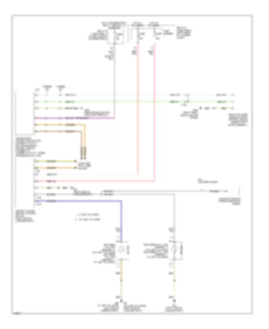
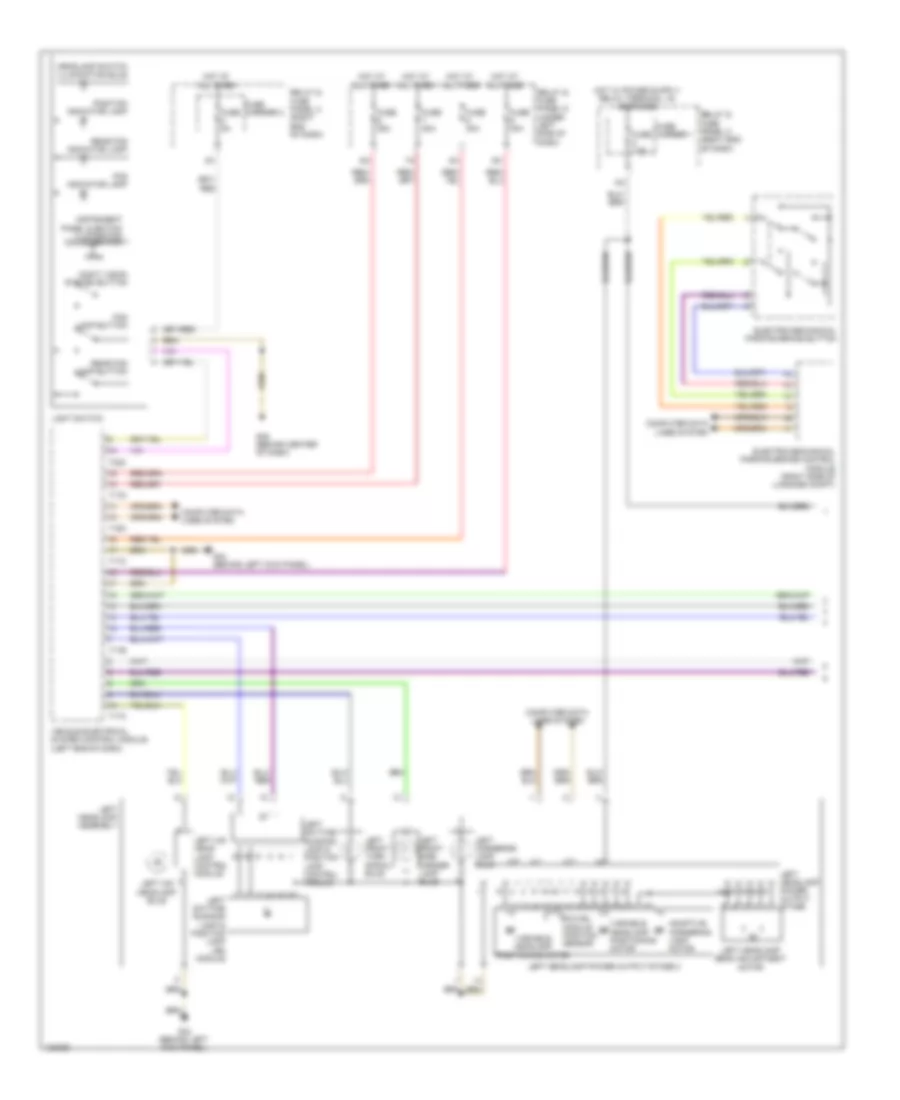
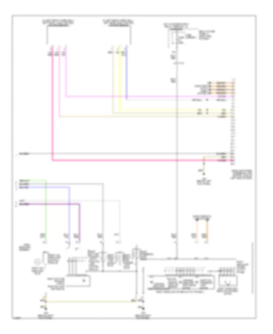
EXTERIOR LIGHTS
Backup Lamps Wiring Diagram for Audi A6 Quattro Prestige 2014
List of elements for Backup Lamps Wiring Diagram for Audi A6 Quattro Prestige 2014:
- 12a
- 7 speed a/t
- 8 speed a/t
- Automatic dimming interior rearview mirror
- Backup
- Comfort system central control module (right side of luggage compt)
- Computer data lines system
- Cvt
- Fuse 20a
- Fuse 30a
- Fuse 5a
- Fuse carrier
- G50 (w/ led taillamps) (left side of luggage compt)
- G51 (right side of luggage compt)
- G51 (w/o led taillamps) (right side of luggage compt)
- G645 (near engine control module on firewall)
- G687 (right front side of center tunnel)
- Hot at all times
- Left rear taillamp assembly 2 (w/o led taillamps) left rear taillamp assembly 1 (w/ led taillamps)
- Relay & fuse panel a (in left plenum chamber e-box)
- Relay & fuse panel f (right rear of luggage compt)
- Right rear tail lamp assembly 2 (w/o led taillamps) right rear tail lamp assembly 1 (w/ led taillamps)
- Selector lever sensor system control module (base of shift lever assembly)
- T17b
- T17r
- T17s
- T32i
- Transmission control module (tcm) (8 speed a/t & cvt) dsg transmission control module (7 speed a/t) (8 speed a/t & cvt: under transmission oil pan)
- W/ led taillamps
- W/o high beam assist
- W/o led taillamps
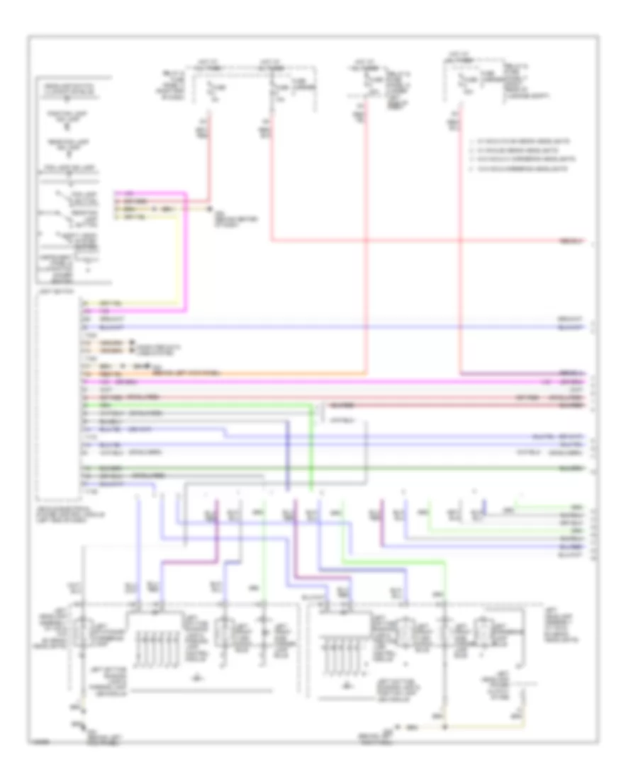
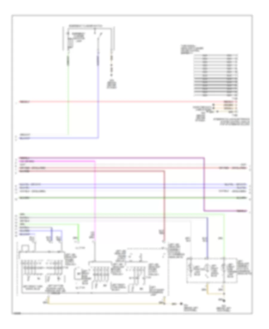
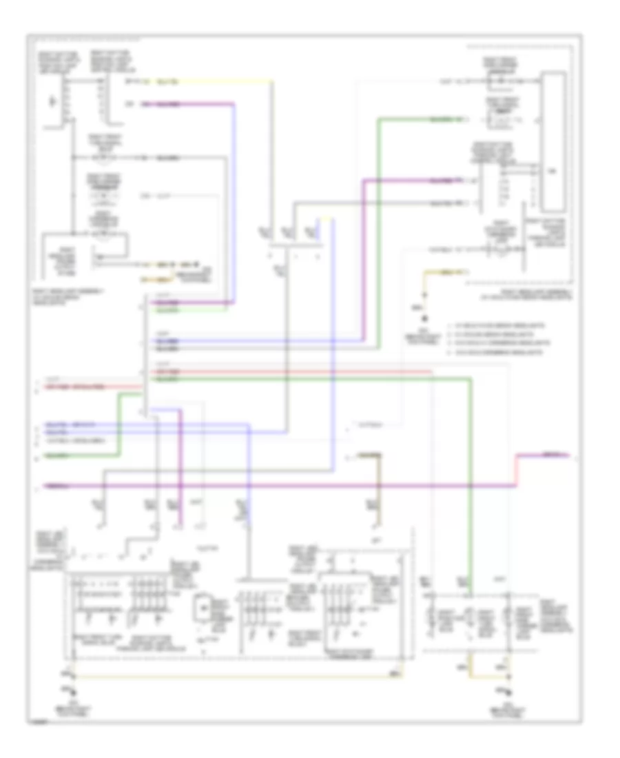
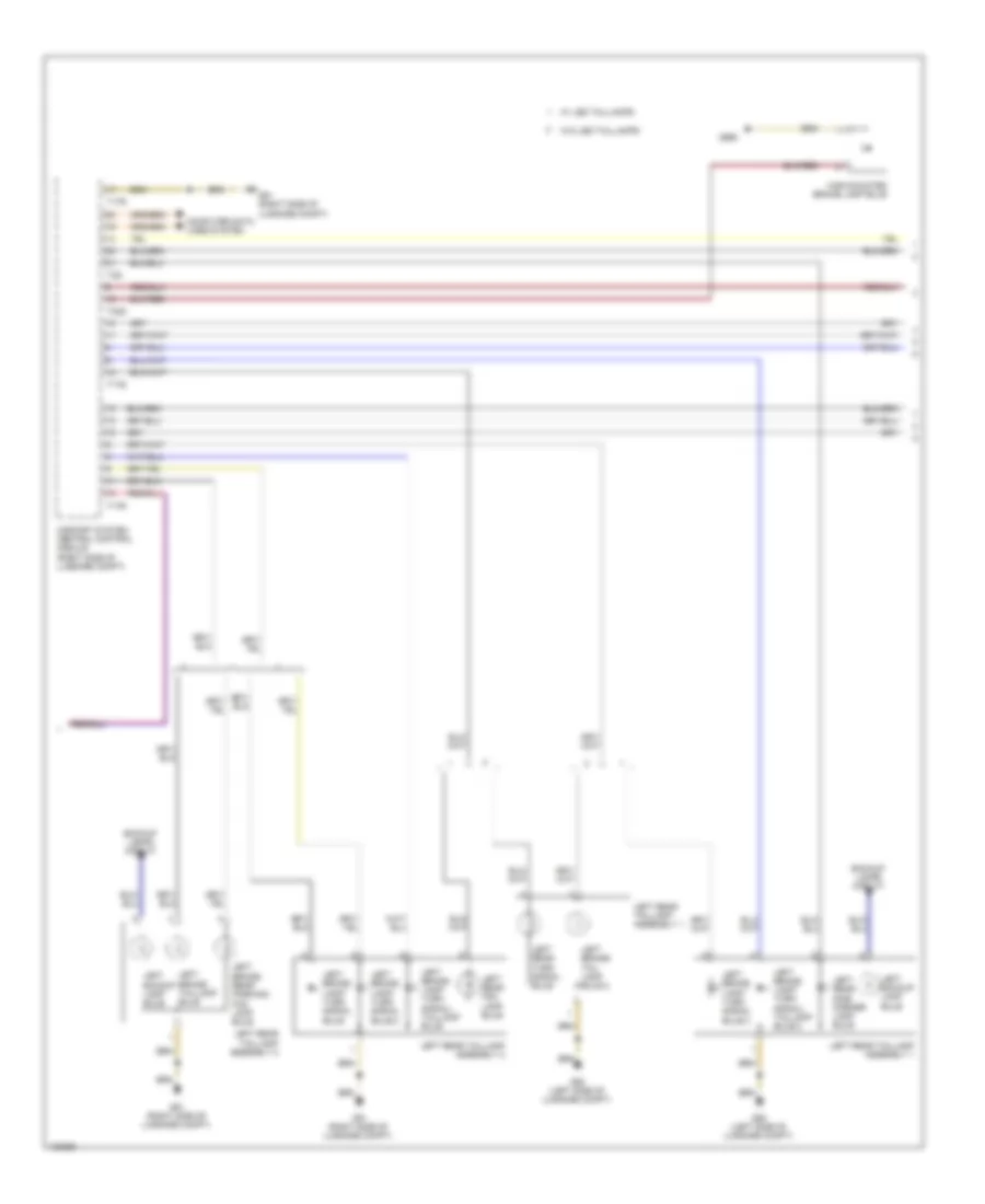
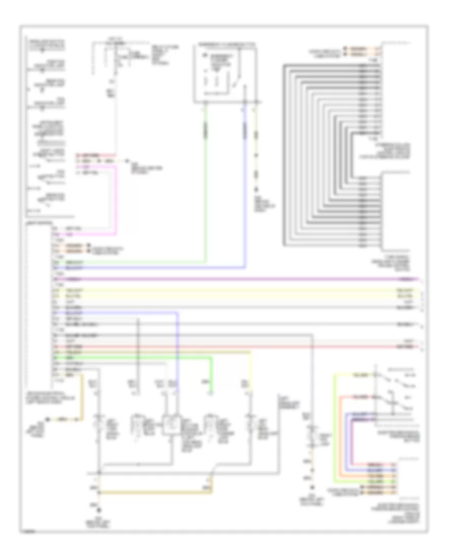
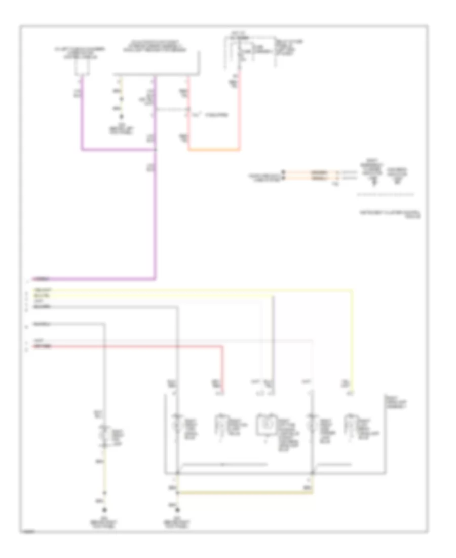
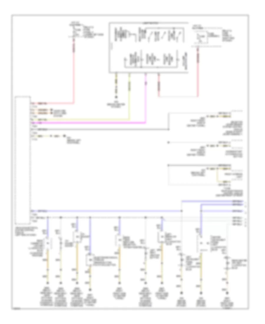
Exterior Lamps Wiring Diagram (1 of 5) for Audi A6 Quattro Prestige 2014
List of elements for Exterior Lamps Wiring Diagram (1 of 5) for Audi A6 Quattro Prestige 2014:
- Computer data lines system
- Fog lamp button
- Fog lamp ind lamp
- Fuse 10a
- Fuse 30a
- Fuse 5a
- Fuse carrier
- G44 (behind left kick panel)
- G45 (behind center of dash)
- Headlamp switch illumination bulb
- Hot at all times
- Instrument panel & illumination dimmer switch
- Left cornering lamp bulb
- Left daytime running lamp & parking lamp control module
- Left daytime running lamp & parking lamp led module
- Left daytime running lamp & position lamp control module
- Left daytime running lamp & position lamp led module
- Left front side marker lamp bulb
- Left front turn signal bulb
- Left headlamp assembly (w/ hid & bi-xenon headlights)
- Left headlamp assembly (w/ hid & w/o bi-xenon headlights)
- Left headlamp power output stage
- Left stationary cornering lamp
- Light switch
- Night vision system button
- Position lamp ind lamp
- Rear fog lamp button
- Rear fog lamp ind lamp
- Relay & fuse panel c (right end of dash)
- Relay & fuse panel d (under left side of dash)
- Relay & fuse panel f (right rear of luggage compt)
- T16c
- T17c
- T17e
- T32c
- Vehicle electrical system control module (left end of dash)
- W/ hid & bi-xenon headlights
- W/ hid & w/o bi-xenon headlights
- W/o hid & cornering headlights
- W/o hid & w/ cornering headlights
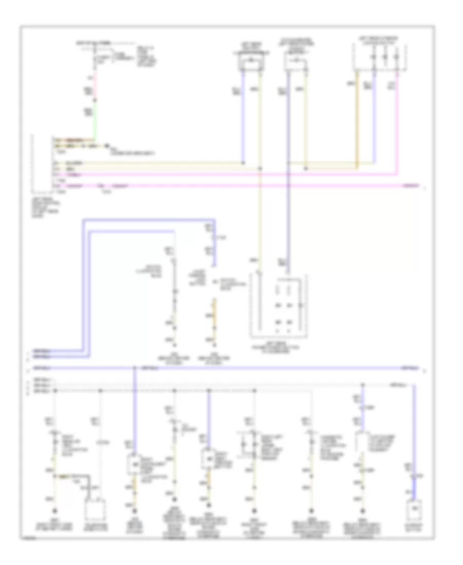
Exterior Lamps Wiring Diagram (2 of 5) for Audi A6 Quattro Prestige 2014
List of elements for Exterior Lamps Wiring Diagram (2 of 5) for Audi A6 Quattro Prestige 2014:
- Computer data lines system
- Emergency flasher indicator lamp
- Emergency flasher switch
- G44 (behind left kick panel)
- G45 (behind center of dash)
- Left daytime running lamp & parking lamp led module
- Left front side marker lamp bulb
- Left front turn signal bulb
- Left front turn signal bulb 2
- Left headlamp assembly (w/o hid & cornering headlights)
- Left led headlamp assembly (w/o hid & w/ cornering headlights)
- Left led headlamp power output module 1
- Left led headlamp power output module 2
- Left led headlamp power output module 3
- Left led headlamp power output module 4 t14h
- Left position lamp bulb
- Left stationary cornering lamp
- Nca
- Steering column electronics system control module (top of steering column)
- T13b
- T14g
- T14h
- T16e
- Turn signal/ headlamp flasher/ cruise control switch
Exterior Lamps Wiring Diagram (3 of 5) for Audi A6 Quattro Prestige 2014
List of elements for Exterior Lamps Wiring Diagram (3 of 5) for Audi A6 Quattro Prestige 2014:
- G43 (behind right kick panel)
- Right cornering lamp bulb
- Right daytime running lamp & parking lamp led module
- Right daytime running lamp & parking light control module
- Right daytime running lamp & position lamp control module
- Right daytime running lamp & position lamp led module
- Right front side marker lamp bulb
- Right front turn signal bulb
- Right front turn signal bulb 2
- Right headlamp assembly (w/ hid & bi-xenon headlights)
- Right headlamp assembly (w/ hid & w/o bi-xenon headlights)
- Right headlamp assembly (w/o hid & cornering headlights)
- Right headlamp power output stage
- Right led headlamp assembly (w/o hid & w/ cornering headlights)
- Right led headlamp power output module 1
- Right led headlamp power output module 2
- Right led headlamp power output module 3
- Right led headlamp power output module 4 t14h
- Right position lamp bulb
- Right stationary cornering lamp
- T14g
- T14h
- W/ hid & bi-xenon headlights
- W/ hid & w/o bi-xenon headlights
- W/o hid & cornering headlights
- W/o hid & w/ cornering headlights
Exterior Lamps Wiring Diagram (4 of 5) for Audi A6 Quattro Prestige 2014
List of elements for Exterior Lamps Wiring Diagram (4 of 5) for Audi A6 Quattro Prestige 2014:
- Backup lamps circuit
- Comfort system central control module (right side of luggage compt)
- Computer data lines system
- G50 (left side of luggage compt)
- G51 (right side of luggage compt)
- G690
- High-mounted brake lamp bulb
- Left backup lamp bulb
- Left brake lamp/ turn signal bulb
- Left brake lamp/ turn signal bulb 2
- Left brake lamp/ turn signal bulb 3
- Left brake lamp/ turn signal/ taillamp bulb
- Left brake lamp/ turn signal/ taillamp bulb 2
- Left brake/ rear parking/ fog lamp bulb
- Left brake/ tail lamp bulb 2
- Left brake/ taillamp bulb
- Left rear fog lamp bulb
- Left rear side marker lamp bulb
- Left rear taillamp assembly 1
- Left rear taillamp assembly 2
- Left rear turn signal bulb
- T17r
- T17s
- T32g
- T32i
- W/ led taillamps
- W/o led taillamps
Exterior Lamps Wiring Diagram (5 of 5) for Audi A6 Quattro Prestige 2014
List of elements for Exterior Lamps Wiring Diagram (5 of 5) for Audi A6 Quattro Prestige 2014:
- (in left plenum chamber) engine control module (ecm)
- 2.0l turbo
- 3.0l sc
- 3.0l turbo diesel
- 4.0l turbo
- Backup lamps circuit
- Brake light switch (top of brake pedal assembly)
- Computer data lines system
- Fuse 5a
- Fuse carrier
- G45 (behind center of dash)
- G51 (right side of luggage compt)
- Instrument cluster
- Instrument cluster control module
- Left license plate lamp
- Left turn ind
- Relay & fuse panel b (left end of dash)
- Right backup lamp bulb
- Right brake lamp/ turn signal bulb
- Right brake lamp/ turn signal bulb 2
- Right brake lamp/ turn signal bulb 3
- Right brake lamp/ turn signal/ taillamp bulb
- Right brake lamp/ turn signal/ taillamp bulb 2
- Right brake/ rear parking/ fog lamp bulb
- Right brake/ tail lamp bulb 2
- Right brake/ taillamp bulb
- Right license plate lamp
- Right rear fog lamp bulb
- Right rear side marker lamp bulb
- Right rear taillamp assembly 1
- Right rear taillamp assembly 2
- Right rear turn signal bulb
- Right turn ind
- T17a
- T17i
- T17o
- T91
- T94
- W/ led taillamps
- W/o led taillamps
GROUND DISTRIBUTION
Ground Distribution Wiring Diagram (1 of 5) for Audi A6 Quattro Prestige 2014
List of elements for Ground Distribution Wiring Diagram (1 of 5) for Audi A6 Quattro Prestige 2014:
- Asr/esp button, rear window shade switch illumination, switch illumination bulb, steering column electronic systems control module, valet parking lock bulb, left side vent position sensor, headlamp range control adjuster (w/ head lamp range control), brake lamp switch, anti-theft immobilizer reader coil, display unit button, left front footwell illumination bulb, light switch & electronic steering column lock control module
- Asr/esp button, tire pressure monitoring control module, image processing control module, hood contact switch 2, right rear footwell lamp, front passenger thorax air bag igniter, right headlamp assembly, right front brake pad wear sensor (if equipped), front passenger seat lumbar support adjustment switch, right front seat belt tensioner control module, front passenger's belt force limiter & front passenger's seat belt tensioner
- Auxiliary heater heating element (3.0l turbo diesel), display opening/ closing motor, emergency flasher switch, cd changer (if equipped), front information display control head, right side vent position sensor, dvd changer, display open/closed stop switch, left/right center vent position sensor & front passenger's side air bag release valve igniter
- Data link connector
- Engine control module
- G43 (behind right kick panel)
- G45 (behind center of dash)
- G601 (2.0l turbo)
- G645 (2.0l turbo) (near engine control module on firewall)
- G645 (3.0l turbo diesel) (near engine control module on firewall)
- Glove compartment lamp switch, valet parking lock button & right front footwell illumination bulb
- Ignition coils 1, 2, 3 & 4 (w/ power output stage)
- Instrument cluster control module
- Power adjustable steering column control module, climatronic control module, fresh air blower control module & active steering control module
- Right front fog lamp bulb, high & low tone horns, right front seat belt tensioner control module (w/ seat belt warning system) & right headlamp assembly
- Subframe mount control module (4.0l turbo)
- Suppressor & engine control module
- T12k
- Transmission control module (tcm), automatic glow time control module, oil pressure switch, reduced oil pressure switch & oil level thermal sensor
- Transmission control module (tcm), coolant recirculation pump, oil level thermal sensor & suppressor
- Windshield projection head up display control module
Ground Distribution Wiring Diagram (2 of 5) for Audi A6 Quattro Prestige 2014
List of elements for Ground Distribution Wiring Diagram (2 of 5) for Audi A6 Quattro Prestige 2014:
- Driver seat backrest bolster heater, driver seat heater & driver backrest heating element
- Engine control module, suppressor & secondary air injection pump motor
- Engine coolant circulation pump 2 after-run coolant pump, oil level thermal sensor & charge air cooling pump
- Engine hood contact switch alarm horn, fiber optic cable for left front sill panel ambient lighting, humidity sensor in fresh air intake duct, a/c pressure/temperature sensor, rear a/c display control head & air quality sensor
- G34 (under driver's seat)
- G44 (behind left kick panel)
- G639
- G645 (4.0l turbo) (near engine control module on firewall)
- G729
- Garage door opener control head, rain/light recognition sensor (if equipped), front interior light, driver vanity mirror lamp contact switch, front passenger vanity mirror lamp contact switch, roof electronics control module (w/ high equipment), camera control module, anti-theft alarm system sensor (w/ interior monitoring) & automatic dimming interior rearview mirror
- Ignition coils 1, 2, 3 & 4 w/ power output stage
- Ignition coils 5, 6, 7 & 8 w/ power output stage
- Left front exterior door handle touch sensor, driver central locking lock unit, driver door control module & left front exterior door handle illumination bulb (w/ auxiliary lamps)
- Left front seat ventilation control module
- Left rear door control module, left rear exterior door handle touch sensor, left rear exterior door handle illumination bulb & left rear central locking lock unit
- Memory seat/steering column adjustment control module, driver multicontour seat compressor, driver multicontour seat control module, driver seat adjustment control head & driver seat lumbar support adjustment switch
- Nox sensor control module, left headlamp assembly, cornering lamp & headlamp range control module & clutch position sensor (m/t)
- Rain/light recognition sensor & directional stabilization assistance windshield defogger
- Roof shade control module & power sunroof control module
- Subwoofer (if equipped)
- T17m
- T23a
- T27c
- T4u
- T6g
- T6h
- T8ac
- Transmission control module
- Vehicle electrical system control module, left front fog lamp bulb, low tone horn, headlamp washer pump, wiper motor control module & left front seat belt tensioner control module (w/ seat belt warning system)
- Vehicle electrical system control module, left headlamp assembly, driver thorax air bag igniter, driver seat lumbar support adjustment switch, left rear footwell lamp, left & right washer nozzle heaters, horn relay, automatic dimming interior rearview mirror relay (if equipped) & garage door opener control module
- W/ comfort seats
- W/o comfort seats
Ground Distribution Wiring Diagram (3 of 5) for Audi A6 Quattro Prestige 2014
List of elements for Ground Distribution Wiring Diagram (3 of 5) for Audi A6 Quattro Prestige 2014:
- 12 v socket 3 & voltage stabilizer (w/ start/stop system)
- Comfort system central control module, electromechanical parking brake control module & valve body
- Digital tv tuner, (w/ bose sound system), tv tuner (w/ bose, bang & olufsen sound system), radio (w/ bose, bang & olufsen sound system), digital sound system control module (w/ bang & olufsen sound system), digital sound system control module 2 & left rear taillamp assembly 1
- Driver side rear thorax air bag igniter (w/ rear side air bags), left rear brake pad wear sensor, luggage compartment lamp, lane change assistance control module 2, right rear window breakage sensor & left rear tail lamp assembly 1
- G50 (left side of luggage compt)
- G51 (right side of luggage compt)
- G659
- G690
- High-mounted brake lamp bulb (w/ insulting/ heat absorbing glass)
- Lane change assistance control module (avant), passenger side rear thorax air bag igniter (w/ rear side air bags), level control system control module, right rear taillamp assembly 1 & left/right rear taillamp assembly 2
- Left & right rear seat message buttons & rear center console ambient lighting bulb 1 & 2 (w/ auxiliary lamps)
- Radio, digital tv tuner (w/o bose sound system), antenna amplifier 2, tv tuner (sedan, w/o bose sound system), antenna amplifier 2 shield, rear lid control module (sedan) & digital sound system control module (w/ bose sound system)
- Rearview camera, rearview camera system control module, level control system compressor relay, parallel parking assistance control module, luggage compartment lamp, high-mounted brake lamp bulb & suppressor
- T17x
Ground Distribution Wiring Diagram (4 of 5) for Audi A6 Quattro Prestige 2014
List of elements for Ground Distribution Wiring Diagram (4 of 5) for Audi A6 Quattro Prestige 2014:
- 3.0l turbo diesel
- 4.0l turbo
- Battery monitoring control module
- Cooling fan control module & cooling fan control module 2 (except 2.0l turbo)
- Cupholder w/ heating & cooling element, fiber optic cable for left/ right rear sill panel ambient lighting, fiber optic cable for right front sill panel ambient lighting, sensor electronics control module, data bus on board diagnostic interface & peripheral camera control module
- G13 (right side of engine compt)
- G18
- G624
- G671 (on left front long member)
- G685 (on right front long member)
- G687 (right front side of center tunnel)
- G688 (below rear seat, near data bus on board diagnostic interface)
- Left/right rear upper body vent position sensor, display opening/closing motor, access/start authorization button, rear temperature selection potentiometer, rear center air vent illumination bulb, display open/closed stop switch, right/left rear upper body vent position sensor, auto hold button, left/right rear air vent illumination bulbs, selector lever sensor system control module & transmission park selector switch
- Nox sensor control module 2, particulate sensor & reducing agent metering system relay
- Power steering control module
- Right rear seat heater, left rear seat heater, right rear backrest heating element, left rear backrest heating element, rear cigarette lighter (w/ smoking package), cigarette lighter (w/ smoking package), 12v socket 3, 12v socket 2, 12v socket 4, transfer fuel pump, fuel pump control module & power socket 12v
- Right rear seat heater, left rear seat heater, right rear backrest heating element, left rear backrest heating element, seat heating control module & left/right seat heating buttons (w/ automatic climate control, basic climatronics)
- T4fm
- Telephone baseplate, front passenger seat 4 pin connector & driver seat 4 pin connector, information electronics control module 1 & multimedia system control head
Ground Distribution Wiring Diagram (5 of 5) for Audi A6 Quattro Prestige 2014
List of elements for Ground Distribution Wiring Diagram (5 of 5) for Audi A6 Quattro Prestige 2014:
- Abs control module
- Active steering control module shield
- All wheel drive control module & rear lid opener control module (if equipped)
- Distance regulation control module & distance regulation control module 2
- Engine control module, transmission control module, charge air cooling pump, after run coolant pump & oil level thermal sensor
- Front passenger backrest heating element & front passenger seat backrest bolster heater (w/o ventilation)
- Front passenger door control module, right front exterior door handle touch sensor, right front central locking system actuator, front passenger central locking lock unit & right front exterior door handle illumination bulb
- Front passenger knee air bag igniter, driver knee air bag igniter, front passenger's side air bag igniter & release valve igniter
- Front passenger seat adjustment control head, front passenger memory seat control module & front passenger seat lumbar support adjustment switch
- Front passenger seat heater, right front seat ventilation control module, front passenger backrest heating element, front passenger seat backrest bolster heater, front passenger seat heating element, front passenger multicontour seat control module & front passenger multicontour seat compressor
- G35 (under front passenger's seat)
- G55 (near abs control module)
- G600 (3.0l sc & 4.0l turbo)
- G601 (3.0l sc & 4.0l turbo)
- G645 (3.0l sc) (near engine control module on firewall)
- G653 (left "d" pillar)
- G654 (right "d" pillar)
- G665 (right side of dash)
- G704 (under driver's seat)
- G744 (right front of spare tire well)
- Ignition coils 1, 2 & 3 w/ power output stage & secondary air injection pump motor
- Ignition coils 1, 2 & 3 w/ power output stage (3.0l sc) & ignition coils 1, 2, 3 & 4 w/ power output stage (4.0l turbo)
- Ignition coils 4, 5 & 6 w/ power output stage
- Ignition coils 4, 5 & 6 w/ power output stage (3.0l sc) & ignition coils 5, 6, 7 & 8 w/ power output stage (4.0l turbo)
- Right rear door control module, right rear exterior door handle touch sensor, right rear central locking lock unit & right rear exterior door handle illumination bulb
- Roof antenna shield, roof antenna, satellite antenna, gps antenna shield, satellite antenna shield & gps antenna
- Suppressor
- T17n
- T23b
- T27d
- T6i
- T8ah
- Telephone antenna, roof antenna shield & telephone antenna shield
- W/ comfort seats
- W/o comfort seats
HEADLIGHTS
Headlights Wiring Diagram, with HID with Bi-Xenon Headlights (1 of 2) for Audi A6 Quattro Prestige 2014
List of elements for Headlights Wiring Diagram, with HID with Bi-Xenon Headlights (1 of 2) for Audi A6 Quattro Prestige 2014:
- Adaptive cornering lamp motor
- Computer data lines system
- Electro-mechanical parking brake button
- Electro-mechanical parking brake control module (right side of luggage compt)
- Fog indicator lamp
- Fog lamp button
- Fuse 20a
- Fuse 30a
- Fuse 35a
- Fuse 5a
- Fuse 7.5a
- Fuse carrier 1
- Fuse carrier 2
- G44 (behind left kick panel)
- G45 (behind center of dash)
- Headlamp switch illumination bulb
- Hot at all times
- Instrument panel & switch illumination dimmer switch
- Left cornering lamp bulb
- Left daytime running lamp & position lamp control module
- Left daytime running lamp & position lamp led module
- Left front side marker lamp bulb
- Left front turn signal bulb
- Left headlamp assembly
- Left headlamp beam adjustment motor
- Left headlamp power output stage
- Left headlamp power output stage 2
- Left hid head- lamp control module
- Left hid headlamp bulb
- Light switch
- Night vision system button
- Position indicator lamp
- Rear fog indicator lamp
- Rear fog lamp button
- Relay & fuse panel c (right end of dash)
- Relay & fuse panel d (under left side of dash)
- Swivel module position sensor
- T16c
- T17c
- T17d
- T17e
- T32c
- Variable headlamp positioning motor
- Variable m headlamp positioning motor
- Vehicle electrical system control module (left end of dash)
Headlights Wiring Diagram, with HID with Bi-Xenon Headlights (2 of 2) for Audi A6 Quattro Prestige 2014
List of elements for Headlights Wiring Diagram, with HID with Bi-Xenon Headlights (2 of 2) for Audi A6 Quattro Prestige 2014:
- (in left front wheelwell) left front level control system sensor
- (in left rear wheelwell) left rear level control system sensor
- 10a
- Adaptive cornering lamp motor
- Computer data lines system
- Fuse 7.5a
- Fuse carrier 1
- G43 (behind right kick panel)
- G44 (behind left kick panel)
- Headlamp range/ cornering lamp control module (left end of dash)
- Relay & fuse panel c (right end of dash)
- Right cornering lamp bulb
- Right daytime running lamp & position lamp control module
- Right daytime running lamp & position lamp led module
- Right front side marker lamp bulb
- Right front turn signal bulb
- Right headlamp assembly
- Right headlamp beam adjustment motor
- Right headlamp power output stage
- Right headlamp power output stage 2
- Right hid headlamp bulb
- Right hid headlamp control module
- Swivel module position sensor
- T17o
- Variable headlamp positioning motor
- Variable m headlamp positioning motor
Headlights Wiring Diagram, with HID without Bi-Xenon Headlights (1 of 2) for Audi A6 Quattro Prestige 2014
List of elements for Headlights Wiring Diagram, with HID without Bi-Xenon Headlights (1 of 2) for Audi A6 Quattro Prestige 2014:
- Computer data lines system
- Electro-mechanical parking brake button
- Electro-mechanical parking brake control module (right side of luggage compt)
- Fog indicator lamp
- Fog lamp button
- Fuse 20a
- Fuse 30a
- Fuse 35a
- Fuse 5a
- Fuse carrier 2
- G44 (behind left kick panel)
- G45 (behind center of dash)
- Headlamp switch illumination bulb
- Hot at all times
- Instrument panel & switch illumination dimmer switch
- Left daytime running lamp & parking lamp control module
- Left daytime running lamp & parking lamp led module
- Left front side marker lamp bulb
- Left front turn signal bulb
- Left headlamp assembly
- Left headlamp beam adjustment motor
- Left hid headlamp bulb
- Left hid headlamp control module
- Left low beam headlamp reflector motor
- Left stationary cornering lamp
- Light switch
- Night vision system button
- Parking indicator lamp
- Rear fog indicator lamp
- Rear fog lamp button
- Relay & fuse panel c (right end of dash)
- Relay & fuse panel d (under left side of dash)
- T16c
- T17c
- T17d
- T17e
- T32c
- Vehicle electrical system control module (left end of dash)
Headlights Wiring Diagram, with HID without Bi-Xenon Headlights (2 of 2) for Audi A6 Quattro Prestige 2014
List of elements for Headlights Wiring Diagram, with HID without Bi-Xenon Headlights (2 of 2) for Audi A6 Quattro Prestige 2014:
- (in left front wheelwell) left front level control system sensor
- (in left rear wheelwell) left rear level control system sensor
- Computer data lines system
- Fuse 7.5a
- Fuse carrier 1
- G43 (behind right kick panel)
- G44 (behind left kick panel)
- Headlamp range control module (left end of dash)
- Pnk
- Relay & fuse panel c (right end of dash)
- Right daytime running lamp & parking lamp control module
- Right daytime running lamp & parking lamp led module
- Right front side marker lamp bulb
- Right front turn signal bulb
- Right headlamp assembly
- Right headlamp beam adjustment motor
- Right hid headlamp bulb
- Right hid headlamp control module
- Right low beam headlamp reflector motor
- Right stationary cornering lamp
- T17g
Headlights Wiring Diagram, without HID with Cornering Headlights (1 of 2) for Audi A6 Quattro Prestige 2014
List of elements for Headlights Wiring Diagram, without HID with Cornering Headlights (1 of 2) for Audi A6 Quattro Prestige 2014:
- (right side of luggage compt) electro-mechanical parking brake control module
- Computer data lines system
- Dimmer switch illumination panel & switch
- Electro-mechanical parking brake button
- Fuse 5a
- Fuse carrier 2
- G44 (behind left kick panel)
- G45 (behind center of dash)
- Hot at all times
- Illumination bulb headlamp switch
- Indicator lamp fog
- Instrument
- Lamp button fog
- Lamp button rear fog
- Left daytime running lamp & parking lamp led module
- Left front side marker lamp bulb
- Left front turn signal bulb
- Left front turn signal bulb 2
- Left headlamp beam adjustment motor
- Left headlamp fan
- Left headlamp temperature sensor 1
- Left high beam headlamp bulb
- Left led headlamp assembly
- Left led headlamp power output module 1
- Left led headlamp power output module 2
- Left led headlamp power output module 3
- Left led headlamp power output module 4 t14h
- Left low beam headlamp bulb
- Left low beam headlamp reflector motor
- Left stationary cornering lamp
- Light switch
- Parking indicator lamp
- Rear fog indicator lamp
- Relay & fuse panel c (right end of dash)
- System button night vision
- T14f
- T14g
- T14h
- T16c
- T17c
- T17d
- T17e
- T32c
- T6ax
- Vehicle electrical system control module (left end of dash)
Headlights Wiring Diagram, without HID with Cornering Headlights (2 of 2) for Audi A6 Quattro Prestige 2014
List of elements for Headlights Wiring Diagram, without HID with Cornering Headlights (2 of 2) for Audi A6 Quattro Prestige 2014:
- (in left front wheelwell) left front level control system sensor
- (in left rear wheelwell) left rear level control system sensor
- Computer data lines system
- Fuse 20a
- Fuse 30a
- Fuse 35a
- Fuse 7.5a
- Fuse carrier 1
- G43 (behind right kick panel)
- G44 (behind left kick panel)
- Headlamp range control module (left end of dash)
- Hot at all times
- Pnk
- Relay & fuse panel c (right end of dash)
- Relay & fuse panel d (under left side of dash)
- Right daytime running lamp & parking lamp led module
- Right front side marker lamp bulb
- Right front turn signal bulb
- Right front turn signal bulb 2
- Right headlamp beam adjustment motor
- Right headlamp fan
- Right headlamp temperature sensor 1
- Right high beam headlamp bulb
- Right led headlamp assembly
- Right led headlamp power output module 1
- Right led headlamp power output module 2
- Right led headlamp power output module 3
- Right led headlamp power output module 4 t14h
- Right low beam headlamp bulb
- Right low beam headlamp reflector motor
- Right stationary cornering lamp
- T14f
- T14g
- T14h
- T17g
- T6ax
Headlights Wiring Diagram, without HID without Cornering Headlights (1 of 2) for Audi A6 Quattro Prestige 2014
List of elements for Headlights Wiring Diagram, without HID without Cornering Headlights (1 of 2) for Audi A6 Quattro Prestige 2014:
- Computer data lines system
- Electro-mechanical parking brake button
- Electro-mechanical parking brake control module (right side of luggage compt)
- Emergency flasher button
- Emergency flasher indicator lamp
- Fog indicator lamp
- Fog lamp button
- Front fog lamp
- Fuse 5a
- Fuse carrier 2
- G44 (behind left kick panel)
- G45 (behind center of dash)
- Headlamp switch illumination bulb
- Hot at all times
- Instrument panel & switch illumination dimmer switch
- Left daytime running lamp bulb & left high beam headlamp bulb
- Left front side marker lamp bulb
- Left front turn signal bulb
- Left headlamp assembly
- Left low beam headlamp bulb
- Left position lamp bulb
- Light switch
- Nca
- Night vision system button
- Position indicator lamp
- Rear fog indicator lamp
- Rear fog lamp button
- Relay & fuse panel c (right end of dash)
- Steering column electronics control module (top of steering column)
- T13b
- T16c
- T16e
- T17c
- T17e
- T32c
- Turn signal/ headlamp flasher/ cruise control switch
- Vehicle electrical system control module (left end of dash)
Headlights Wiring Diagram, without HID without Cornering Headlights (2 of 2) for Audi A6 Quattro Prestige 2014
List of elements for Headlights Wiring Diagram, without HID without Cornering Headlights (2 of 2) for Audi A6 Quattro Prestige 2014:
- (in automatic day/night interior mirror assembly) rain/light recognition sensor
- (in left plenum chamber) wiper motor control module
- Computer data lines system
- Fuse 5a
- Fuse carrier 3
- G43 (behind right kick panel)
- G44 (behind left kick panel)
- High-beam indicator lamp
- Hot at all times
- If equipped
- Instrument cluster control module
- Relay & fuse panel b (left end of dash)
- Right daytime running lamp bulb & right high beam headlamp bulb
- Right emergency flasher indicator lamp
- Right front fog lamp
- Right front side marker lamp bulb
- Right front turn signal bulb
- Right headlamp assembly
- Right low beam headlamp bulb
- Right position lamp bulb
- T32
- T4u
HORN
Horn Wiring Diagram for Audi A6 Quattro Prestige 2014
List of elements for Horn Wiring Diagram for Audi A6 Quattro Prestige 2014:
- (behind center of dash) g45
- Air bag spiral spring/ return spring w/ slip ring (top of steering column)
- Computer data lines system
- Fuse 15a
- Fuse 25a
- Fuse carrier
- G43 (behind right kick panel)
- G44 (behind left kick panel)
- High tone horn
- Horn relay (on relay & fuse panel d)
- Horn signal activation
- Hot at all times
- Low tone horn
- Nca
- Power adjustment steering column control module (on steering column)
- Relay & fuse panel b (left end of dash)
- Relay & fuse panel c (right end of dash)
- Steering column adjustment switch
- Steering column electronic systems control module (top of steering column)
- T12v
- T16c
- T16e
- T17g
- T18d
- T32a
- T6n
- Vehicle electrical system control module (left end of dash)
INSTRUMENT CLUSTER
Instrument Cluster Wiring Diagram for Audi A6 Quattro Prestige 2014
List of elements for Instrument Cluster Wiring Diagram for Audi A6 Quattro Prestige 2014:
- (behind center of dash) g45
- 10a
- 2.0l turbo
- 3.0l sc
- 3.0l turbo diesel
- 4.0l turbo
- Abs indicator lamp
- Air bag indicator lamp
- Brake fluid level warning switch (on brake fluid reservoir)
- Computer data lines system
- Diesel electronics indicator lamp
- Display unit
- Display unit button
- Engine control module (in left plenum chamber)
- Engine electronics indicator lamp
- Fiber optic
- Fuel gauge
- Fuel level sensor & fuel level sensor 2 (top of fuel tank)
- Fuse 5a
- Fuse carrier 1
- G45 (behind center of dash)
- G645 (near engine control module on firewall)
- High beam indicator lamp
- Hot at all times
- Instrument cluster control module
- Left turn signal indicator lamp
- Light switch
- Nca
- Night vision system button
- Night vision system control module
- Oil pressure switch (2.0l turbo: left front of engine block) (4.0l turbo: rear of engine under charge air cooler housing)
- Oil pressure switch (on oil filter housing)
- Pnk
- Relay & fuse panel b (left end of dash)
- Relay & fuse panel c (right end of dash)
- Right emergency flasher indicator lamp
- Sensor 1
- Sensor 2
- Sound systems
- T105
- T16c
- T17f
- T17h
- T2bm
- T32
- T32a
- T32c
- T91
- T94
- Vehicle electrical system control module (left end of dash)
- Windshield projection head up display button
- Windshield projection head up display control module (top left side of dash)
INTERIOR LIGHTS
Courtesy Lamps Wiring Diagram (1 of 6) for Audi A6 Quattro Prestige 2014
List of elements for Courtesy Lamps Wiring Diagram (1 of 6) for Audi A6 Quattro Prestige 2014:
- (below rear seat, near data bus on board diagnostic interface) g688
- Fiber optic cable for right rear sill panel ambient lighting (w/ auxiliary lamps)
- Fuse 30a
- Fuse carrier
- G35 (under front passenger's seat)
- Hot at all times
- Nca
- Relay & fuse panel f (right rear of luggage compt)
- Right rear central locking lock unit (w/ door closing aid)
- Right rear central locking lock unit (w/o door closing aid)
- Right rear door ambient lighting bulb
- Right rear door contact switch
- Right rear door control module (in right rear door)
- Right rear door opener illumination
- Right rear door storage compartment illumination bulb
- Right rear door warning lamp (w/ auxiliary lamps)
- Right rear entry lamp
- Right rear exterior door handle illumination bulb
- T10aa
- T16o
- T17d
- T20h
- T23b
- T27d
- T5ad
- W/ auxiliary lamps
- W/ door closing aid
- W/o door closing aid
Courtesy Lamps Wiring Diagram (2 of 6) for Audi A6 Quattro Prestige 2014
List of elements for Courtesy Lamps Wiring Diagram (2 of 6) for Audi A6 Quattro Prestige 2014:
- (5)
- 11a
- Computer data lines system
- Driver reading lamp
- Driver reading lamp button
- Front interior lamp
- Front interior light
- Front passenger reading lamp
- Front passenger reading lamp button
- Fuse 30a
- Fuse 5a
- G43 (behind right kick panel)
- G44 (behind left kick panel)
- G45 (behind center of dash)
- G51 (right side of luggage compt)
- G688 (below rear seat, near data bus on board diagnostic interface)
- Glove compartment lamp switch
- Glove compartment light
- Hot at all times
- If equipped
- Interior lighting switch
- Left center armrest illumination bulb
- Left front footwell illumination bulb
- Left rear footwell light
- Left rear interior lamp
- Left rear reading lamp switch
- Mirrors system
- Nca
- Rear center console ambient lighting bulb 1 (w/ auxiliary lamps)
- Rear center console ambient lighting bulb 2 (w/ auxiliary lamps)
- Rear center console ambient lighting contact switch
- Rear interior light assembly
- Relay & fuse panel d (under left side of dash)
- Right center armrest illumination bulb
- Right front footwell illumination bulb
- Right rear footwell light
- Right rear interior lamp
- Right rear reading lamp switch
- T10ab
- T10ac
- T12k
- T16c
- T17c
- T17d
- T17f
- T17h
- T17i
- T17m
- T17n
- T17x
- T32a
- T32c
- Vehicle electrical system control module (left end of dash)
Courtesy Lamps Wiring Diagram (3 of 6) for Audi A6 Quattro Prestige 2014
List of elements for Courtesy Lamps Wiring Diagram (3 of 6) for Audi A6 Quattro Prestige 2014:
- (w/ auxiliary lamps) left rear door warning lamp
- Fuse 30a
- Fuse carrier
- G34 (under driver's seat)
- G688 (below rear seat, near data bus on board diagnostic interface)
- Hot at all times
- Lamps
- Left rear central locking lock unit (w/ door closing aid)
- Left rear central locking lock unit (w/o door closing aid)
- Left rear door ambient lighting bulb
- Left rear door contact switch
- Left rear door control module (in left rear door)
- Left rear door opener illumination
- Left rear door storage compartment illumination bulb
- Left rear entry lamp
- Left rear exterior door handle illumination bulb
- Left rear sill panel ambient lighting/ fiber optic cable (w/ auxiliary lamps)
- Nca
- Relay & fuse panel b (left end of dash)
- T10z
- T16n
- T20g
- T27c
- T5ac
- W/ auxiliary
- W/ auxiliary lamps
- W/ door closing aid
- W/o door closing aid
Courtesy Lamps Wiring Diagram (4 of 6) for Audi A6 Quattro Prestige 2014
List of elements for Courtesy Lamps Wiring Diagram (4 of 6) for Audi A6 Quattro Prestige 2014:
- (w/ door closing aid) front passenger central locking lock unit
- (w/o door closing aid) front passenger central locking lock unit
- Computer data lines system
- Front passenger door ambient lighting bulb
- Front passenger door contact switch
- Front passenger door control module (in front passenger's door)
- Front passenger door opener illumination bulb
- Front passenger door storage compartment illumination bulb
- Front passenger door warning lamp (w/ auxiliary lamps)
- Fuse 30a
- Fuse carrier
- G35 (under front passenger's seat)
- G688 (below rear seat, near data bus on board diagnostic interface)
- Hot at all times
- Nca
- Relay & fuse panel f (right rear of luggage compt)
- Right front entry lamp
- Right front exterior door handle illumination bulb
- Right front sill panel ambient lighting/fiber optic cable (w/ auxiliary lamps)
- T20f
- T23b
- T32l
- T5ab
- T6at
- T8x
- W/ auxiliary lamps
- W/ door closing aid
- W/o door closing aid
Courtesy Lamps Wiring Diagram (5 of 6) for Audi A6 Quattro Prestige 2014
List of elements for Courtesy Lamps Wiring Diagram (5 of 6) for Audi A6 Quattro Prestige 2014:
- (behind left kick panel) g44
- (center front of roof)
- Comfort system central control module (right side of luggage compt)
- Computer data lines system
- Driver vanity mirror lamp
- Driver vanity mirror lamp contact switch
- Front interior lamp
- Front interior lamp button
- Front passenger vanity mirror lamp
- Front passenger vanity mirror lamp contact switch
- Fuse 20a
- Fuse carrier
- G50 (left side of luggage compt)
- G51 (right side of luggage compt)
- Garage door opener button 1
- Garage door opener button 2
- Garage door opener button 3
- Hot at all times
- Left front reading lamp
- Left front reading lamp button
- Left rear interior lamp
- Left rear reading lamp switch
- Luggage compartment lamp
- Mirrors system
- Rear interior light
- Rear reading lamp front button
- Relay & fuse panel f (right rear of luggage compt)
- Right front reading lamp
- Right front reading lamp button
- Right rear interior lamp
- Right rear reading lamp switch 1
- Roof electronics control module (w/ highline equipment)
- T10ab
- T10ac
- T17r
- T17s
- T32i
Courtesy Lamps Wiring Diagram (6 of 6) for Audi A6 Quattro Prestige 2014
List of elements for Courtesy Lamps Wiring Diagram (6 of 6) for Audi A6 Quattro Prestige 2014:
- (under driver's seat) g34
- (w/ auxiliary lamps) driver door storage compartment illumination bulb
- (w/o auxiliary lamps) left front entry lamp
- Anti-lock brakes system
- Computer data lines system
- Driver central locking lock unit (w/ door closing aid)
- Driver central locking lock unit (w/o door closing aid)
- Driver door ambient lighting bulb
- Driver door contact switch
- Driver door opener illumination bulb
- Driver door warning lamp
- Driver's door control module (in driver's front door)
- Fuse 30a
- Fuse carrier
- G34 (under driver's seat)
- G44 (behind left kick panel)
- Hot at all times
- Left front entry lamp
- Left front exterior door handle illumination bulb
- Left front sill panel ambient lighting/ fiber optic cable
- Nca
- Relay & fuse panel b (left end of dash)
- T10w
- T20e
- T23a
- T32k
- T5aa
- T6as
- W/ auxiliary lamps
- W/ door closing aid
- W/o door closing aid
Instrument Illumination Wiring Diagram (1 of 4) for Audi A6 Quattro Prestige 2014
List of elements for Instrument Illumination Wiring Diagram (1 of 4) for Audi A6 Quattro Prestige 2014:
- 12v power socket
- 12v socket
- Access/start authorization button
- Button fog lamp
- Button lamp
- Center instrument panel vent illumination bulb
- Computer data lines system
- Electromechanical parking brake button/ auto hold button
- Front interior light
- Fuse 30a
- Fuse 5a
- Fuse carrier 2
- G44 (behind left kick panel)
- G45 (behind center of dash)
- G687 (right front side of center tunnel)
- G688 (below rear seat, near data bus on board diagnostic interface)
- Headlamp switch
- Hot at all times
- Illumination bulb
- Illumination dimmer
- Indicator lamp
- Indicator lamp fog lamp
- Instrument panel
- Lamp indicator lamp rear fog
- Left instrument panel vent illumination bulb
- Left rear air vent illumination bulb
- Left seat heating button
- Light switch
- Night vision
- Position lamp
- Rear center air vent illumination bulb
- Rear cigarette lighter illumination bulb (w/ smoking package)
- Rear fog
- Rear temp- erature selection potentiometer
- Relay & fuse panel c (right end of dash)
- Relay & fuse panel d (under left side of dash)
- Roof electronics control module (center front of roof)
- Selector lever sensor system control module (base of shift lever assembly)
- Switch
- System button
- T10ab
- T16c
- T17c
- T32a
- T32c
- Vehicle electrical system control module (left end of dash)
Instrument Illumination Wiring Diagram (2 of 4) for Audi A6 Quattro Prestige 2014
List of elements for Instrument Illumination Wiring Diagram (2 of 4) for Audi A6 Quattro Prestige 2014:
- (w/o sunshade) left rear power window button
- 12v socket
- 30a
- Cigarette lighter illumination bulb (w/ smoking package)
- Cup holder w/ heating & cooling element
- Fuse 5
- Fuse carrier 3
- G34 (under driver's seat)
- G45 (behind center of dash)
- G687 (right front side of center tunnel)
- G688 (below rear seat, near data bus on board diagnostic interface)
- Hot at all times
- Left rear ashtray illumination bulb
- Left rear door control module (in left rear door)
- Left rear interior locking switch
- Left rear power window button (w/ sunshade)
- Relay & fuse panel b (left end of dash)
- Right instrument panel vent illumination bulb
- Right rear air vent illumination bulb
- Right seat heating button
- Right/left rear upper body vent position sensor
- Sunroof button
- Switch illumination bulb
- T12k
- T16n
- T20g
- T27c
- T4er
- T5g
- T6g
- Telephone base plate
- Valet parking lock button
Instrument Illumination Wiring Diagram (3 of 4) for Audi A6 Quattro Prestige 2014
List of elements for Instrument Illumination Wiring Diagram (3 of 4) for Audi A6 Quattro Prestige 2014:
- 30a
- Display unit button
- Fuse 7
- Fuse carrier 2
- G35 (under front passenger's seat)
- G45 (behind center of dash)
- Hot at all times
- Rear window shade switch illumination
- Relay & fuse panel f (right rear of luggage compt)
- Right rear ashtray illumination bulb
- Right rear door control module (in right rear door)
- Right rear door power window button (w/o sunhade)
- Right rear interior locking switch
- Right rear power window button (w/ sunhade)
- T16o
- T20h
- T27d
Instrument Illumination Wiring Diagram (4 of 4) for Audi A6 Quattro Prestige 2014
List of elements for Instrument Illumination Wiring Diagram (4 of 4) for Audi A6 Quattro Prestige 2014:
- (if equipped) alarm system deactivation switch
- Computer data lines system
- Driver door control module (in driver front door)
- Driver interior locking switch
- Driver memory seat control head
- Driver's door power window control head
- Front passenger door control module (in front passenger door)
- Front passenger door window regulator switch
- Front passenger interior locking switch
- Front passenger memory seat control head
- Fuse 30a
- Fuse carrier
- G34 (under driver's seat)
- G35 (under front passenger's seat)
- Hot at all times
- Lane change assistance button
- Mirror adjustment switch
- Rear lid remote release button
- Relay & fuse panel b (left end of dash)
- Relay & fuse panel f (right rear of luggage compt)
- T20e
- T20f
- T23a
- T23b
- T32k
- T32l
- T4bk
- T5aa
MEMORY SYSTEMS
Memory Mirrors Wiring Diagram (1 of 2) for Audi A6 Quattro Prestige 2014
List of elements for Memory Mirrors Wiring Diagram (1 of 2) for Audi A6 Quattro Prestige 2014:
- Adjustment switch
- Computer data lines system
- Driver memory seat control head & emergency off button
- Driver seat memory button
- Driver's door control module (in driver's front door)
- Folding mirror adjustment switch
- Front passenger's door control module (in passenger's front door)
- G34 (under driver's seat)
- G35 (under front passenger's seat)
- Interior lights system
- Memory seat positions 1 & 2 button
- Mirror adjustment switch
- Off
- Pnk
- Red
- Selector switch
- T16l
- T16m
- T20e
- T20f
- T32k
- T4bk
Memory Mirrors Wiring Diagram (2 of 2) for Audi A6 Quattro Prestige 2014
List of elements for Memory Mirrors Wiring Diagram (2 of 2) for Audi A6 Quattro Prestige 2014:
- (if equipped) day/night
- (if equipped) motor folding
- Day/night (if equipped)
- Driver's side exterior mirror
- Folding motor (if equipped)
- Front passenger's side exterior mirror
- Fuse 30a
- Fuse carrier
- Heater
- Horizontal motor
- Horizontal sensor (if equipped)
- Hot at all times
- Lane change
- Navigation system
- Pnk
- Red
- Relay & fuse panel b (left end of dash)
- Relay & fuse panel f (right rear of luggage compt)
- T23a
- T23b
- Turn signal
- Vertical motor
- Vertical sensor (if equipped)
Memory Seat Wiring Diagram (1 of 4) for Audi A6 Quattro Prestige 2014
List of elements for Memory Seat Wiring Diagram (1 of 4) for Audi A6 Quattro Prestige 2014:
- (if equipped) driver's seat lumbar support adjustment switch
- (w/ comfort seats)
- 15a
- Computer data lines system
- Driver backrest adjustment switch
- Driver power seat adjustment circuit breaker 1
- Driver seat
- Driver seat angle adjustment switch
- Driver seat height adjustment switch
- Driver seat switch module 2 (w/ comfort seats)
- Driver side massage function button
- Driver's backrest adjustment motor
- Driver's seat adjustment control head (w/o comfort seats) driver seat switch module (w/ comfort seats)
- Driver's seat angle adjustment motor
- Driver's seat depth adjustment motor (w/ comfort seat)
- Driver's seat forward/back adjustment motor
- Driver's seat height adjustment motor
- Driver's seat lumbar support curvature adjustment motor
- Driver's seat lumbar support height adjustment motor
- Forward/back adjustment switch
- G34 (under driver's seat)
- Hot at all times
- Memory seat/ steering column adjustment control module
- Nca
- Red
- T12x
- T12y
- T17m
- T32m
- T8ad
- W/ comfort seats
- W/o comfort seats
Memory Seat Wiring Diagram (2 of 4) for Audi A6 Quattro Prestige 2014
List of elements for Memory Seat Wiring Diagram (2 of 4) for Audi A6 Quattro Prestige 2014:
- (not used)
- (under driver's seat) g34
- Computer data
- Computer data lines system
- Driver memory seat control head & emergency off button
- Driver multicontour seat compressor
- Driver seat memory button
- Driver seat valve block 1
- Driver seat valve block 2
- Driver's door control module (in driver's front door)
- Driver's multicontour seat control module (w/ comfort seats)
- Fuse 30a
- Fuse carrier
- G34 (under driver's seat)
- Hot at all times
- Interior lights system
- Lines system
- Memory seat positions 1&2 button
- Memory seat/ steering column adjustment control module
- Nca
- Off
- Red
- Relay & fuse panel b (left end of dash)
- Seats
- System
- T12y
- T16q
- T17m
- T20e
- T23a
- T32k
- T6az
Memory Seat Wiring Diagram (3 of 4) for Audi A6 Quattro Prestige 2014
List of elements for Memory Seat Wiring Diagram (3 of 4) for Audi A6 Quattro Prestige 2014:
- (if equipped) front passenger seat lumbar support adjustment switch
- (w/ comfort seats) front passenger seat depth adjustment motor
- 15a
- Backrest adjustment switch
- Computer data lines system
- Forward/back adjustment switch
- Front passenger backrest adjustment switch
- Front passenger massage function button (w/ comfort seats)
- Front passenger memory seat control module
- Front passenger seat lumbar support curvature adjustment motor
- Front passenger seat lumbar support height adjustment motor
- Front passenger seat switch module 2 (w/ comfort seats)
- Front passenger's
- Front passenger's angle adjustment motor
- Front passenger's backrest adjustment motor
- Front passenger's power seat adjustment circuit breaker 1
- Front passenger's seat adjustment control head (w/o comfort seats) front passenger seat switch module (w/ comfort seats)
- Front passenger's seat angle adjustment switch
- Front passenger's seat forward/back adjustment motor
- Front passenger's seat height adjustment motor
- Front passenger's seat height adjustment switch
- Fuse 7.5a
- Fuse carrier 2
- G35 (under front passenger's seat)
- Hot at all times
- Red
- Relay & fuse panel b (left end of dash)
- Seat forward/back adjustment switch
- Seat height adjustment switch
- T12aa
- T12ab
- T17n
- T32n
- T8ae
- W/ comfort seats
- W/o comfort seats
Memory Seat Wiring Diagram (4 of 4) for Audi A6 Quattro Prestige 2014
List of elements for Memory Seat Wiring Diagram (4 of 4) for Audi A6 Quattro Prestige 2014:
- (under front passenger's seat)
- (under front passenger's seat) g35
- Computer data
- Computer data lines system
- Front passenger memory seat button
- Front passenger memory seat control head & emergency off button
- Front passenger memory seat control module
- Front passenger multicontour seat compressor
- Front passenger multicontour seat control module (w/ comfort seats)
- Front passenger seat valve block 1
- Front passenger seat valve block 2
- Front passenger's door control module (in passenger's front door)
- Fuse 30a
- Fuse 7.5a
- Fuse carrier
- G35
- G35 (under front passenger's seat)
- Hot at all times
- Interior lights system
- Lines system
- Memory seat positions 1&2 button
- Nca
- Off
- Red
- Relay & fuse panel b (left end of dash)
- Relay & fuse panel f (right rear of luggage compt)
- Seats
- System
- T12ab
- T16r
- T17n
- T20f
- T23b
- T32l
- T6ba
Steering Column Memory Wiring Diagram for Audi A6 Quattro Prestige 2014
List of elements for Steering Column Memory Wiring Diagram for Audi A6 Quattro Prestige 2014:
- (behind center of dash) g45
- (left end of dash) vehicle electrical system control module
- Computer data lines system
- Driver memory seat control head & emergency off button
- Driver seat memory button
- Driver's door control module (in driver's front door)
- Fuse 10a
- Fuse 25a
- Fuse 5a
- Fuse carrier
- G45 (behind center of dash)
- Hot at all times
- Interior lights system
- Memory seat positions 1 & 2 button
- Off
- Power adjustable steering column control module (on steering column)
- Relay & fuse panel c (right end of dash)
- Steering column adjustment switch
- Steering column axial adjustment sensor & forward/back adjustment motor
- Steering column electronic systems control module (top of steering column)
- Steering column vertical adjustment sensor/motor
- T16c
- T16e
- T17g
- T20e
- T32k
- T6n
NAVIGATION
Lane Change Assistance Wiring Diagram for Audi A6 Quattro Prestige 2014
List of elements for Lane Change Assistance Wiring Diagram for Audi A6 Quattro Prestige 2014:
- Computer data lines system
- Directional stabilization assistance button
- Driver door control module (in driver's front door)
- Driver's exterior rearview mirror
- Fuse 5a
- Fuse carrier 4
- G50 (left side of luggage compt)
- G51 (right side of luggage compt)
- Lane change assistance button
- Lane change assistance control module (behind right end of rear bumper trim)
- Lane change assistance control module 2 (behind left end of rear bumper trim)
- Nca
- Passenger exterior rearview mirror
- Relay & fuse panel f (right rear of luggage compt)
- Relay (terminal 15) energized
- Steering column electronics systems control module (top of steering column)
- T16e
- T20e
- T23a
- T23b
- T2et
- T2eu
- T2ev
- T2ew
- T32k
- T5aa
- Warning lamp assistance lane change
Navigation Wiring Diagram, with Navigation Plus (1 of 2) for Audi A6 Quattro Prestige 2014
List of elements for Navigation Wiring Diagram, with Navigation Plus (1 of 2) for Audi A6 Quattro Prestige 2014:
- (right front side of center tunnel)
- 10a
- Computer data lines system
- Display opening/ closing motor & switch
- External audio source connection
- External audio source connection (w/ external audio source connection-audi music interface)
- Fuse 5a
- Fuse 7.5a
- Fuse carrier
- G45 (behind center of dash)
- G687
- G687 (right front side of center tunnel)
- Hot at all times
- Information electronics control module 1
- Multimedia system control head (if equipped)
- Nca
- Red
- Relay & fuse panel c (right end of dash)
- Relay & fuse panel f (right rear of luggage compt)
- T10t
- T12f
- T17h
- T17o
- T32a
- T4aa
- T5g
- T5q
- T8g
- T8h
- T8p
- Telephone base plate
- Touch pad control module
- Vehicle electrical system control module (left end of dash)
- W/ audi music interface
- W/ aux-in connection
Navigation Wiring Diagram, with Navigation Plus (2 of 2) for Audi A6 Quattro Prestige 2014
List of elements for Navigation Wiring Diagram, with Navigation Plus (2 of 2) for Audi A6 Quattro Prestige 2014:
- (left side of luggage compt) (w/ cd changer) digital tv tuner
- (right side of luggage compt) (if equipped) rearview camera system control module
- Display unit button
- Dvd changer
- Fiber optic
- Front information display control head
- G45 (behind center of dash)
- G653 (left "d" pillar)
- G654 (right "d" pillar)
- Gps antenna
- Information electronics control module 1
- Instrument cluster control module
- Interior lights system
- Left front microphone
- Microphone unit
- Most data bus circuit
- Nca
- Radio
- Right front microphone
- Roof antenna
- Satellite antenna
- T12g
- T2as
- T2at
- T2au
- T2aw
- T2bn
- T2bo
- T2bx
- T2cg
- T2ch
- T2ck
- T2df
- T2dl
- T32
- T4dc
- T4dd
- T8ag
- Telephone antenna
Navigation Wiring Diagram, with Radio Plus (1 of 3) for Audi A6 Quattro Prestige 2014
List of elements for Navigation Wiring Diagram, with Radio Plus (1 of 3) for Audi A6 Quattro Prestige 2014:
- Aux-in connection
- External audio source connection
- External audio source connection (w/ external audio source connection-audi music interface)
- Front information display control head
- Fuse 5a
- Fuse 7.5a
- Fuse carrier
- G45 (behind center of dash)
- Hot at all times
- Information electronics control module 1
- Left rear mid-bass speaker
- Left rear treble speaker
- Nca
- Red
- Relay & fuse panel c (right end of dash)
- T12e
- T17o
- T27c
- T4de
- T4ey
- T4z
- T8ag
- T8e
- W/ external audio source
- W/ external audio source connection-audi music interface
Navigation Wiring Diagram, with Radio Plus (2 of 3) for Audi A6 Quattro Prestige 2014
List of elements for Navigation Wiring Diagram, with Radio Plus (2 of 3) for Audi A6 Quattro Prestige 2014:
- (left "d" pillar) antenna amplifier 2
- (left side of rear lid) antenna amplifier
- (right "d" pillar) antenna amplifier 3
- Antenna
- Digital radio antenna
- G653 (left "d" pillar)
- Gps antenna
- Information electronics control module 1
- Left front micro- phone
- Left front mid-bass speaker
- Left front treble speaker
- Microphone unit
- Nca
- Radio antenna
- Right front micro- phone
- Right front mid-bass speaker
- Right front treble speaker
- Right rear mid-bass speaker
- Right rear treble speaker
- Roof antenna
- Satellite antenna
- T17l
- T23a
- T23b
- T27d
- T2au
- T2av
- T2ax
- T2bt
- T2bw
- T2cg
- T2ch
- T4ab
- T4aq
- T4df
- T4y
- T5l
- Telephone baseplate
Navigation Wiring Diagram, with Radio Plus (3 of 3) for Audi A6 Quattro Prestige 2014
List of elements for Navigation Wiring Diagram, with Radio Plus (3 of 3) for Audi A6 Quattro Prestige 2014:
- (right front side of center tunnel) g687
- (right side of luggage compt) (w/ rearview camera system) rearview camera system control module
- (w/ audi sound system) center speaker
- (w/ audi sound system) subwoofer
- Computer data lines system
- Display opening/closing motor & switch
- Display unit button
- Fiber optic
- Fuse 20a
- Fuse carrier
- G45 (behind center of dash)
- G687 (right front side of center tunnel)
- Hot at all times
- Information electronics control module 1
- Instrument cluster control module
- Interior lights system
- Most data bus circuit
- Multimedia system control head
- Nca
- Relay & fuse panel f (right rear of luggage compt)
- T12c
- T12d
- T17h
- T17l
- T2aw
- T2df
- T32
- T8f
- T8p
Parking Assistant Wiring Diagram for Audi A6 Quattro Prestige 2014
List of elements for Parking Assistant Wiring Diagram for Audi A6 Quattro Prestige 2014:
- Bumper)
- Computer data lines system
- Front parking aid warning buzzer (left side of dash)
- Front/center console control head
- Fuse 5a
- Fuse carrier 4
- G45 (behind center of dash)
- G51 (right side of luggage compt)
- Left front center parking aid sensor
- Left front parallel parking assistance sensor (behind left corner of front bumper)
- Left front parking aid sensor (behind left inner & outer sides of front bumper)
- Left rear center parking aid sensor
- Left rear parallel parking assistance sensor (behind left corner of rear
- Left rear parking aid sensor (behind left inner & outer sides of rear bumper)
- Parallel parking aid indicator lamp (if equipped)
- Parallel parking assistance button (if equipped)
- Parallel parking assistance control module (right side of luggage compt)
- Parking aid button
- Parking aid indicator lamp
- Rear parking aid warning buzzer (right side of luggage compt)
- Relay & fuse panel f (right rear of luggage compt)
- Right front center parking aid sensor
- Right front parallel parking assistance sensor (behind right corner of front bumper)
- Right front parking aid sensor (behind right inner & outer sides of front bumper)
- Right rear center parking aid sensor
- Right rear parallel parking assistance sensor (behind right corner of rear bumper)
- Right rear parking aid sensor (behind right inner & outer sides of rear bumper)
- T10k
- T12q
- T12w
- T16i
- T17g
- T17q
- T6ai
- T8i
Peripheral Camera Wiring Diagram for Audi A6 Quattro Prestige 2014
List of elements for Peripheral Camera Wiring Diagram for Audi A6 Quattro Prestige 2014:
- 10a
- Computer data lines system
- Front peripheral camera (center of front grille)
- Fuse 5a
- Fuse carrier 3
- G688 (below rear seat, near data bus on board diagnostic interface)
- Hot at all times
- Information electronics control module 1
- Left peripheral camera (in left exterior rearview mirror assembly)
- Nca
- Peripheral camera control module (under front passenger's seat)
- Rear peripheral camera (integral to rear lid handle)
- Relay & fuse panel f (right rear of luggage compt)
- Right peripheral camera (in right exterior rearview mirror assembly)
- T12c
- T12g
- T18f
- T2lt
- T5an
- T5ao
- T5ap
- T5aq
- T5av
- T5aw
- T5ax
- T5ay
- T5az
- W/ rmc sound system
- W/o rmc sound system
Rear Camera Wiring Diagram for Audi A6 Quattro Prestige 2014
List of elements for Rear Camera Wiring Diagram for Audi A6 Quattro Prestige 2014:
- (integral to rear lid handle)
- 10a
- Comfort system central control module (right side of luggage compt)
- Computer data lines system
- Fuse 5a
- Fuse carrier
- G51 (right side of luggage compt)
- Ground distribution system
- Hot at all times
- Information electronics control module 1
- Nca
- Pins: 1-38 (not used)
- Pins: 49-54 (not used)
- Rear lid lock cylinder unlock button
- Rearview camera
- Rearview camera system control module (right side of luggage compt)
- Relay & fuse panel f (right rear of luggage compt)
- T12c
- T12g
- T2df
- T2dg
- T2eq
- T2er
- T2es
- T32g
- T32i
- T54a
- W/ rmc sound system
- W/o rmc sound system
POWER DISTRIBUTION
Power Distribution Wiring Diagram (1 of 10) for Audi A6 Quattro Prestige 2014
List of elements for Power Distribution Wiring Diagram (1 of 10) for Audi A6 Quattro Prestige 2014:
- (not used)
- 10a
- 11a
- 12a
- 15a
- 2.0l turbo
- 3.0l sc
- 3.0l turbo diesel
- 4.0l turbo
- 40a
- 50a
- 60a
- 80a
- Abs control module
- Abs control module fuse 1
- Air bag control module
- Alarm horn
- Anti-theft alarm system sensor (w/ interior monitoring)
- Automatic glow time control module
- Battery
- Battery interrupt igniter
- Battery jump start terminal (right rear corner of engine compt)
- Battery monitoring control module
- Comfort system central control module
- Coolant fan control (fc) module
- Coolant fan control (fc) module 2 (3.0l sc & 4.0l turbo)
- Coolant fan fuse 40a/60a/80a
- Coolant fan second speed fuse 40a/60a/80a
- Driver power seat adjustment circuit breaker 1
- Driver seat lumbar support adjustment switch (if equipped)
- Except 2.0l turbo &
- Front interior lamp
- Front passenger's memory seat control module (w/ memory)
- Front passenger's power seat adjustment circuit breaker 1
- Front passenger's seat adjustment control head (w/o memory)
- Front passenger's seat lumbar support adjustment switch (if equipped)
- Fuse 20a
- Fuse 30a
- Fuse 35a
- Fuse 5a
- Fuse n/a
- G645 (near engine control module on firewall)
- Generator & voltage regulator
- Glow plug fuse
- Heating element fuse 1
- Heating element fuse 2
- High heat output relay
- Low heat output relay
- Main fuse carrier (in luggage compt on battery)
- Memory seat/ steering column adjustment control module
- Nca
- Power steering control module
- Red
- Relay & fuse panel d (under left side of dash)
- Roof electronics control module (w/ highline equipment)
- Safety fuse 1 150a
- Safety fuse 2 110a
- Safety fuse 3 150a
- Secondary air injection (air) pump fuse (except 2.0l turbo)
- Secondary air injection (air) pump relay
- Sensor electronics control module
- Starter
- Suppressor (in right plenum chamber e-box)
- T10ab
- T12aa
- T12x
- T17c
- T17d
- T17e
- T17m
- T17n
- T1d
- T2fa
- T32g
- T4fm
- T4fn
- T6bf
- T6d
- Terminal 30 wire junction (in center plenum chamber)
- To relay & fuse panel b (diagram 4 of 10)
- To relay & fuse panel b (diagram 5 of 10)
- To relay & fuse panel c (diagram 3 of 10)
- To relay & fuse panel f (diagram 6 of 10)
- Vehicle electrical system control module
- W/ auxiliary heater
- W/ interior monitoring
Power Distribution Wiring Diagram (2 of 10) for Audi A6 Quattro Prestige 2014
List of elements for Power Distribution Wiring Diagram (2 of 10) for Audi A6 Quattro Prestige 2014:
- (not used)
- 10a
- 11a
- 14a
- 15a
- 16a
- 17a
- After-run coolant pump
- Bank 2 turbocharger recirculation valve
- Camshaft adjustment valve 1
- Camshaft adjustment valve 2
- Charge air cooling pump
- Coolant fan control module
- Coolant fan control module 2
- Cylinder head coolant valve
- Engine control module
- Engine coolant circulation pump 2
- Evap canister purge regulator valve 1
- Exhaust camshaft adjuster 1 for cylinder 2
- Exhaust camshaft adjuster 1 for cylinder 3
- Exhaust camshaft adjuster 1 for cylinder 5
- Exhaust camshaft adjuster 1 for cylinder 8
- Exhaust camshaft adjuster 2 for cylinder 2
- Exhaust camshaft adjuster 2 for cylinder 3
- Exhaust camshaft adjuster 2 for cylinder 5
- Exhaust camshaft adjuster 2 for cylinder 8
- Exhaust camshaft adjustment valve 1
- Exhaust camshaft adjustment valve 2
- From main fuse carrier (diagram 1 of 10)
- Fuel metering valve
- Fuel metering valve 2
- Fuse 10a
- Fuse 15a
- Fuse 30a
- Fuse 5a
- Heated oxygen sensor & oxygen sensor heater
- Heated oxygen sensor 2 & oxygen sensor heater 2
- Ignition coil 1 w/ power output stage
- Ignition coil 2 w/ power output stage
- Ignition coil 3 w/ power output stage
- Ignition coil 4 w/ power output stage
- Ignition coil 5 w/ power output stage
- Ignition coil 6 w/ power output stage
- Ignition coil 7 w/ power output stage
- Ignition coil 8 w/ power output stage
- Intake camshaft adjuster 1 for cylinder 2
- Intake camshaft adjuster 1 for cylinder 3
- Intake camshaft adjuster 1 for cylinder 5
- Intake camshaft adjuster 1 for cylinder 8
- Intake camshaft adjuster 2 for cylinder 2
- Intake camshaft adjuster 2 for cylinder 3
- Intake camshaft adjuster 2 for cylinder 5
- Intake camshaft adjuster 2 for cylinder 8
- Intake manifold runner control valve
- Map controlled engine cooling thermostat
- Nca
- Oil level thermal sensor
- Oil pressure regulation valve
- Oxygen sensor 2 after catalytic converter & oxygen sensor heater 2 after catalytic converter
- Oxygen sensor after three way catalytic converter & oxygen sensor heater 1 after catalytic converter
- Piston cooling nozzle control valve
- Red
- Relay & fuse panel a (in left plenum chamber e-box)
- Secondary air injection pump relay
- Secondary air injection solenoid valve
- Secondary air injection solenoid valve 2
- T17b
- T4fm
- T4fn
- T8ay
- T91
- To relay & fuse panel b (diagram 4 of 10)
- Transmission control module
- Turbo- charger recirculation valve
- Wastegate bypass regulator valve
Power Distribution Wiring Diagram (3 of 10) for Audi A6 Quattro Prestige 2014
List of elements for Power Distribution Wiring Diagram (3 of 10) for Audi A6 Quattro Prestige 2014:
- (if equipped) transmission fluid cooling valve
- (not used)
- 10a
- 11a
- 12a
- 13a
- 14a
- 15a
- 16a
- 2.0l turbo
- 3.0l sc
- 3.0l turbo diesel
- 3.0l turbo diesel & 4.0l turbo
- 4.0l turbo
- Anti-theft immobilizer reader coil
- Cd & dvd changer
- Climatronic control module
- Cornering lamp & headlamp range control module
- Data link connector
- Electronic steering column lock control module
- Engine control module
- Fresh air blower control module
- From main fuse carrier (diagram 1 of 10)
- From relay & fuse panel b (diagram 5 of 10)
- From voltage stabilizer (diagram 6 of 10)
- Front information display control head
- Fuse 10a
- Fuse 15a
- Fuse 25a
- Fuse 30a
- Fuse 40a
- Fuse 5a
- Fuse 7.5a
- Fuse carrier
- Fuse n/a
- Headlamp range control module
- Headlights
- Information electronics control module 1
- Instrument cluster control module
- Left headlamp assembly
- Left headlamp power output stage
- Light switch
- Multimedia system control head
- Nca
- Power adjustable steering column control module
- Red
- Relay & fuse panel a (in left plenum chamber e-box)
- Relay & fuse panel b (left end of dash)
- Relay & fuse panel c (right end of dash)
- Right headlamp assembly (w/ hid & bi-xenon headlights)
- Right headlamp power output stage
- Starter relay
- Starter relay 2
- Steering column electronics control module
- T16e
- T170
- T17a
- T17g
- T17h
- T17o
- T20c
- T32
- T6n
- T8ag
- T8f
- T8g
- T8q
- T91
- To relay & fuse panel a (diagram 8 of 10)
- To relay & fuse panel a (diagram 9 of 10)
- To relay & fuse panel f (diagram 7 of 10)
- Transmission control module
- W/ heated steering wheel
- W/ hid & bi-xenon
- W/ hid w/o bi-xenon headlights & w/o hid w/ cornering lamps
- W/ navigation plus
- W/ radio plus
- W/ start/stop system
- W/o start/stop system
- Windshield projection head up display control module
Power Distribution Wiring Diagram (4 of 10) for Audi A6 Quattro Prestige 2014
List of elements for Power Distribution Wiring Diagram (4 of 10) for Audi A6 Quattro Prestige 2014:
- (not used)
- 10a
- 11a
- 12a
- 2.0l turbo
- 3.0l sc
- 3.0l turbo diesel
- 4.0l turbo
- Access/start authorization button
- Brake lamp switch
- Comfort system central control module
- Computer data lines system
- Digital sound system control module 2 (w/ bang & olufsen sound)
- Driver seat lumbar support adjustment switch (if equipped)
- Electro- mechanical parking brake button
- Exhaust door control unit (4.0l turbo)
- Exhaust door control unit 2 (4.0l turbo)
- From main fuse carrier (diagram 1 of 10)
- From relay & fuse panel f (diagram 6 of 10)
- Front passenger multicontour seat control
- Fuel pump control module
- Fuse 15a
- Fuse 25a
- Fuse 30a
- Fuse 5a
- Fuse 7.5a
- Fuse carrier
- Fuse n/a
- G45 (behind center of dash)
- G687 (right front side of center tunnel)
- Horn relay
- If equipped
- Interior lights system
- Left rear door control module
- Level control system control module
- Nca
- Rain/ light recognition sensor
- Rear lid control module
- Red
- Relay & fuse panel b (left end of dash)
- Relay & fuse panel f (right rear of luggage compt)
- Right rear door control module
- Start/stop mode button
- Start/stop mode ind lamp
- T10k
- T12ab
- T16c
- T17b
- T17i
- T17m
- T17n
- T17r
- T20g
- T20h
- T27c
- T27d
- T32a
- T32c
- T32g
- T32i
- T4bx
- T4u
- T4y
- T5l
- T6ai
- T6ba
- T9a
- Telephone base plate
- Vehicle electrical system control module
- Wiper motor control module
Power Distribution Wiring Diagram (5 of 10) for Audi A6 Quattro Prestige 2014
List of elements for Power Distribution Wiring Diagram (5 of 10) for Audi A6 Quattro Prestige 2014:
- (diagram 1 of 10)
- (not used)
- 10a
- 11a
- 12a
- A/c pressure/ temperature sensor
- Abs control module
- Active steering control module
- Air bag control module
- Air quality sensor/ humidity sensor in fresh air intake duct (comfort)
- Asr/esp button & front passenger air bag disabled indicator lamp
- Automatic dimming interior rearview mirror
- Automatic dimming interior rearview mirror relay
- Camera control module
- Data bus on board diagnostic interface
- Distance regulation control module
- Distance regulation control module 2
- Driver door control module
- Driver multicontour seat control module
- Electro- mechanical parking brake button
- From main fuse carrier h
- Front passenger seat lumbar support adjustment switch (if equipped)
- Fuse 10a
- Fuse 15a
- Fuse 20a
- Fuse 30a
- Fuse 35a
- Fuse 5a
- Fuse 7.5a
- Fuse carrier
- Garage door opener control head
- Garage door opener control module (if equipped)
- Humidity sensor in fresh air intake duct (basic)
- Image processing control module (w/ acc)
- Left rear door control module
- Nca
- Passenger occupant detection system control module
- Power steering control module
- Power sunroof control module
- Rear a/c display control head
- Red
- Relay & fuse panel b (left end of dash)
- Roof shade control module (long wheel base)
- Seat heating control module
- Sensor electronics control module
- Sub- frame mount control module (4.0l turbo)
- T10e
- T12y
- T17g
- T17i
- T17m
- T17n
- T20a
- T20e
- T20g
- T27c
- T5k
- T6ak
- T6al
- T6az
- T6g
- T8m
- Tire pressure monitoring control module
- To relay & fuse panel b (diagram 3 of 10)
- W/ adaptive cruise control
Power Distribution Wiring Diagram (6 of 10) for Audi A6 Quattro Prestige 2014
List of elements for Power Distribution Wiring Diagram (6 of 10) for Audi A6 Quattro Prestige 2014:
- (not used)
- (right side of luggage compt) g51
- 10a
- 11a
- 12a
- 2.0l turbo
- 3.0l sc
- 3.0l turbo diesel
- 3a (not used)
- 4.0l turbo
- 400w stabilizer
- All-wheel drive control module
- Automatic dimming interior rearview mirror relay (if equipped)
- Comfort system central control module
- Computer data lines system
- Digital sound system control module (w/ bose, bang & olufsen sound)
- Digital tv tuner
- Electro- mechanical parking brake control module
- Engine control module
- From main fuse carrier (diagram 1 of 10)
- From relay & fuse panel f (diagram 7 of 10)
- Front passenger door control module
- Fuel tank leak detection control module (w/ fuel system diagnostic pump)
- Fuse 15a
- Fuse 20a
- Fuse 30a
- Fuse 30a (or 20a)
- Fuse 35a
- Fuse 40a
- Fuse 5a
- Fuse 7.5a
- Fuse carrier
- Fuse carrier 1
- Fuse n/a
- Information electronics control module 1
- Level control system compressor relay
- Multimedia control head 2
- Nca
- Peripheral camera control module
- Radio (basic)
- Radio (w/ bose, bang & olufsen sound)
- Rear a/c display control head
- Rear window defogger relay
- Rearview camera system control module
- Red
- Relay & fuse panel a (in left plenum chamber e-box)
- Relay & fuse panel f (right rear of luggage compt)
- Right front seat ventilation control module
- Seat heating control module
- Starter
- Starter relay
- Sub frame mount control unit (4.0l turbo)
- T10i
- T120
- T12af
- T17b
- T17s
- T18f
- T20d
- T20f
- T23b
- T38
- T3r
- T54a
- T6i
- T8f
- T91
- T94
- To relay & fuse panel c (diagram 3 of 10)
- To relay & fuse panel f (diagram 4 of 10)
- To sockets relay (diagram 7 of 10)
- Tv tuner
- Voltage stabilizer (w/ start/stop system) (in spare tire well)
- W/ start/stop system
- W/ start/stop system &
- W/o start/stop system
Power Distribution Wiring Diagram (7 of 10) for Audi A6 Quattro Prestige 2014
List of elements for Power Distribution Wiring Diagram (7 of 10) for Audi A6 Quattro Prestige 2014:
- (not used)
- (w/ seat belt warning switch)
- 10a
- 11a
- 12a
- 12v socket
- All-wheel drive control module
- Cigarette lighter
- Comfort system central control module
- Comfort system central control module (if equipped)
- Control module
- Data link connector
- Electro- mechanical parking brake
- From relay & fuse panel b f (diagram 3 of 10)
- From relay & fuse panel f (diagram 6 of 10)
- Fuse 10a
- Fuse 20a
- Fuse 25a
- Fuse 5a
- Fuse carrier
- Fuse n/a
- G51 (right side of luggage compt)
- G688 (below rear seat, near data bus on board diagnostic interface)
- Interior lights system
- Lane change assistance control module
- Lane change assistance control module 2
- Left front seat belt tensioner control module
- Level control system control module (if equipped)
- Nca
- Parking aid & parallel parking assistance control module (if equipped)
- Rear cigarette lighter
- Red
- Relay & fuse panel f (right rear of luggage compt)
- Right front seat belt tensioner control module
- Selector lever sensor system control module
- Sockets relay (on relay & fuse panel f)
- T16i
- T17i
- T32a
- T32g
- T32i
- T4ac
- T4ad
- T4ca
- T4w
- T4x
- T9a
- To voltage stabilizer (diagram 6 of 10)
- Transmission park selector switch & shift lock solenoid (7 speed a/t & cvt)
- Transmission park selector switch & shift lock solenoid (8 speed a/t)
- Vehicle electrical system control module
Power Distribution Wiring Diagram (8 of 10) for Audi A6 Quattro Prestige 2014
List of elements for Power Distribution Wiring Diagram (8 of 10) for Audi A6 Quattro Prestige 2014:
- 10a
- 11a
- 12a
- 14a
- 16a
- 17a
- Auxiliary engine coolant pump relay
- Camshaft adjustment valve 1
- Camshaft adjustment valve 2
- Charge air cooling pump
- Control valve
- Coolant fan control module
- Coolant fan control module 2
- Cooling circuit solenoid valve
- Crankcase ventilation shut-off valve
- Engine control module
- Evap canister purge regulator valve 1
- From main fuse carrier (diagram 1 of 10)
- From relay & fuse panel b (diagram 3 of 10)
- Fuel metering valve
- Fuse 10a
- Fuse 15a
- Fuse 20a
- Fuse 5a
- Heated oxygen sensor & oxygen sensor heater
- Heated oxygen sensor 2 & oxygen sensor heater 2
- Ignition coil 1 w/ power output stage
- Ignition coil 2 w/ power output stage
- Ignition coil 3 w/ power output stage
- Ignition coil 4 w/ power output stage
- Ignition coil 5 w/ power output stage
- Ignition coil 6 w/ power output stage
- Intake manifold runner
- Left elctrohydraulic engine mount solenoid valve
- Nca
- Oil level thermal sensor
- Oil pressure regulation valve
- Oxygen sensor 2 after catalytic converter & oxygen sensor heater 2 after catalytic converter
- Oxygen sensor after three way catalytic converter & oxygen sensor heater 1 after catalytic converter
- Red
- Relay & fuse panel a (in left plenum chamber e-box)
- Right elctrohydraulic engine mount solenoid valve
- Secondary air injection pump relay
- Secondary air injection solenoid valve
- Secondary air injection solenoid valve 2
- T14b
- T94
- To relay & fuse panel b (diagram 4 of 10)
- Transmission control module
Power Distribution Wiring Diagram (9 of 10) for Audi A6 Quattro Prestige 2014
List of elements for Power Distribution Wiring Diagram (9 of 10) for Audi A6 Quattro Prestige 2014:
- (not used)
- 10a
- 11a
- 12a
- 14a
- A/t
- Cam adjustment actuator 1
- Cam adjustment actuator 2
- Cam adjustment actuator 3
- Cam adjustment actuator 4
- Cam adjustment actuator 5
- Cam adjustment actuator 6
- Cam adjustment actuator 7
- Cam adjustment actuator 8
- Camshaft adjustment valve 1
- Coolant fan control module
- Coolant recir- culation pump
- Cvt
- Engine control module
- Evap canister purge regulator valve 1
- From main fuse carrier (diagram 1 of 10)
- From relay & fuse panel b (diagram 3 of 10)
- Fuel pressure regulator valve
- Fuse 10a
- Fuse 15a
- Fuse 20a
- Fuse 5a
- Heated oxygen sensor & oxygen sensor heater
- Ignition coil 1 w/ power output stage
- Ignition coil 2 w/ power output stage
- Ignition coil 3 w/ power output stage
- Ignition coil 4 w/ power output stage
- Intake manifold runner control valve
- Left elctrohydraulic engine mount solenoid valve 1
- Mass airflow sensor
- Nca
- Oil level thermal sensor
- Oil pressure regulation valve
- Oxygen sensor after three way catalytic converter & oxygen sensor heater 1 after catalytic converter
- Red
- Relay & fuse panel a (in left plenum chamber e-box)
- T14b
- T17b
- T94
- To relay & fuse panel b (diagram 4 of 10)
- Transmission control module
- Turbo- charger recirculation valve
- Wastegate bypass regulator valve
Power Distribution Wiring Diagram (10 of 10) for Audi A6 Quattro Prestige 2014
List of elements for Power Distribution Wiring Diagram (10 of 10) for Audi A6 Quattro Prestige 2014:
- 10a
- 11a
- 16a
- Automatic glow time control module
- Coolant fan control module
- Coolant fan control module 2
- Cylinder head coolant valve
- Egr cooler switch-over valve
- Engine control module
- From main fuse carrier (diagram 1 of 10)
- Fuel metering valve
- Fuel pressure regulator valve
- Fuse 10a
- Fuse 15a
- Fuse 15a (or 10a)
- Fuse 5a
- Heated oxygen sensor
- High heat output relay
- Left electrohydraulic engine mount solenoid valve
- Low heat output relay
- Map controlled engine cooling thermostat
- Mass airflow sensor
- Nca
- Nox sensor control module
- Nox sensor control module 2/ nox sensor 2
- Oil level thermal sensor
- Oil pressure regulation valve
- Particulate sensor
- Red
- Relay & fuse panel a (in left plenum chamber e-box)
- Right electrohydraulic engine mount solenoid valve
- T10l
- T17b
- T17g
- T91
- To relay & fuse panel b (diagram 4 of 10)
- Transmission control module
POWER DOOR LOCKS
Power Door Locks Wiring Diagram (1 of 6) for Audi A6 Quattro Prestige 2014
List of elements for Power Door Locks Wiring Diagram (1 of 6) for Audi A6 Quattro Prestige 2014:
- (w/ anti-theft alarm system & interior monitoring & towing prevention) alarm system deactivation switch
- Anti-lock brakes system
- Central locking safe indicator lamp
- Computer data lines system
- Driver central locking lock unit (w/ door closing aid)
- Driver central locking lock unit (w/o door closing aid)
- Driver door central locking system motor
- Driver door closing assist motor (if equipped)
- Driver door contact switch
- Driver interior locking switch
- Driver lock cylinder contact switch
- Driver's door control module (in driver door)
- Fuse 30a
- Fuse carrier
- G34 (under driver's seat)
- Hot at all times
- Interior lights system
- Left front central locking system actuator
- Rear lid remote release button
- Red
- Relay & fuse panel b (left end of dash)
- T10w
- T20e
- T23a
- T27c
- T32k
- T3au
- W/ door closing aid
- W/o door closing aid
Power Door Locks Wiring Diagram (2 of 6) for Audi A6 Quattro Prestige 2014
List of elements for Power Door Locks Wiring Diagram (2 of 6) for Audi A6 Quattro Prestige 2014:
- (in left rear door) left rear door control module
- (under front passenger's seat) g35
- Fuse 30a
- Fuse carrier
- G34 (under driver's seat)
- Hot at all times
- Interior lights system
- Left rear interior locking switch
- Relay & fuse panel f (right rear of luggage compt)
- Right rear closing assist motor (if equipped)
- Right rear door control module (in right rear door)
- Right rear interior locking switch
- T16n
- T16o
- T20g
- T20h
- T23a
- T270
- T27c
- T27d
Power Door Locks Wiring Diagram (3 of 6) for Audi A6 Quattro Prestige 2014
List of elements for Power Door Locks Wiring Diagram (3 of 6) for Audi A6 Quattro Prestige 2014:
- (w/ door closing aid) left rear central locking lock unit
- (w/o door closing aid) left rear central locking lock unit
- Computer data lines system
- G34 (under driver's seat)
- G35 (under front passenger's seat)
- Instrument cluster control module
- Interior access/start authorization antenna 2 (center rear of luggage compt)
- Left rear central locking system actuator
- Left rear central locking system motor
- Left rear child safety lock contact switch
- Left rear child safety lock motor
- Left rear closing assist motor (if equipped)
- Left rear door contact switch
- Right rear central locking lock unit (w/ door closing aid)
- Right rear central locking lock unit (w/o door closing aid)
- Right rear central locking system actuator
- Right rear child m
- Right rear child safety lock contact switch
- Right rear child safety lock motor
- Right rear door central locking system motor
- Right rear door contact switch
- Safety lock motor
- T10aa
- T10z
- T32
- T3aw
- T3ax
- W/ door closing aid
- W/o door closing aid
Power Door Locks Wiring Diagram (4 of 6) for Audi A6 Quattro Prestige 2014
List of elements for Power Door Locks Wiring Diagram (4 of 6) for Audi A6 Quattro Prestige 2014:
- (right side of luggage compt) comfort system central control module
- Access/start authorization button
- Antenna amplifier 2 (left "d" pillar)
- Anti-theft immobilizer reader coil (center of dash)
- C (right end of dash)
- Central locking & anti-theft alarm system antenna
- Computer data lines system
- Door closing assist control module (center rear of luggage compt)
- Fuel filler door unlock motor (right side of luggage compt)
- Fuse 20a
- Fuse 5a
- Fuse carrier
- G34 (under driver's seat)
- G35 (under front passenger's seat)
- G45 (behind center of dash)
- G51 (right side of luggage compt)
- G687 (right front side of center tunnel)
- Hot at all times
- Interior access/start authorization antenna 1 (under center console)
- Left access/start authorization antenna (in left rear door)
- Left front exterior door handle touch sensor (in left front door handle assembly)
- Left rear exterior door handle touch sensor (in left rear door handle assembly)
- Nca
- Rear lid closing assist motor
- Rear lid closing assist/lock stop switch
- Rear lid closing assist/unlock stop switch
- Rear lid lock cylinder unlock button
- Rear lid lock/ alarm/central locking switch & rear lid central locking system motor
- Relay & fuse panel
- Relay & fuse panel f (right rear of luggage compt)
- Right access/start authorization antenna (in right rear door)
- Right front exterior door handle touch sensor (in right front door handle assembly)
- Right rear exterior door handle touch sensor (in right rear door handle assembly)
- T17h
- T17r
- T17s
- T23a
- T23b
- T27c
- T27d
- T2co
- T32g
- T32h
- T32i
Power Door Locks Wiring Diagram (5 of 6) for Audi A6 Quattro Prestige 2014
List of elements for Power Door Locks Wiring Diagram (5 of 6) for Audi A6 Quattro Prestige 2014:
- (in right plenum chamber) alarm horn
- (in roof console) (w/ interior monitoring) anti-theft alarm system sensor
- (in steering column) electronic steering column lock control module
- (left end of dash) vehicle electrical system control module
- Computer data lines system
- Engine hood contact switch (center front of engine compt)
- Front passenger interior locking switch
- Fuse 5a
- Fuse carrier
- G43 (behind right kick panel)
- G44 (behind left kick panel)
- G45 (behind center of dash)
- G50 (left side of luggage compt)
- G51 (right side of luggage compt)
- Hood contact switch 2
- Horns system
- Hot at all times
- Interior lights system
- Nca
- Rear lid control module (left side of luggage compt)
- Rear lid lock button in luggage compartment
- Relay & fuse panel c (right end of dash)
- Relay & fuse panel d (under left side of dash)
- Selector lever sensor system control module (base of shift lever assembly)
- T16c
- T170
- T17c
- T26b
- T2af
- T2ay
- T32a
- T32c
- T4bx
- W/ interior monitoring
Power Door Locks Wiring Diagram (6 of 6) for Audi A6 Quattro Prestige 2014
List of elements for Power Door Locks Wiring Diagram (6 of 6) for Audi A6 Quattro Prestige 2014:
- (under front passenger's seat) g35
- Computer data lines system
- Front passenger central locking lock unit (w/ door closing aid)
- Front passenger central locking lock unit (w/o door closing aid)
- Front passenger closing assist motor (if equipped)
- Front passenger door central locking system motor
- Front passenger door contact switch
- Front passenger door control module (in front passenger door)
- Fuse 30a
- Fuse carrier
- G35 (under front passenger's seat)
- Hot at all times
- Relay & fuse panel f (right rear of luggage compt)
- Right front central locking system actuator
- T20f
- T23b
- T32l
- T3av
- T8x
- W/ door closing aid
- W/o door closing aid
POWER MIRRORS
Power Mirrors Wiring Diagram for Audi A6 Quattro Prestige 2014
List of elements for Power Mirrors Wiring Diagram for Audi A6 Quattro Prestige 2014:
- (right side of luggage compt)
- Automatic day/night interior mirror relay (if equipped) (on relay & fuse panel d)
- Automatic dimming interior rearview mirror
- Automatic high beam assist control module (if equipped)
- Comfort system central control module
- Computer data lines system
- Driver's door control module (in driver's door)
- Front interior lamp assembly
- Front passenger's door control module (in front passenger's door)
- Fuse 5a
- Fuse carrier
- G44 (behind left kick panel)
- Hot at all times
- Humidity sensor (if equipped)
- Interior mirror relay
- Light recognition sensor
- Relay & fuse panel b (left end of dash)
- Relay & fuse panel f (right rear of luggage compt)
- Right tail lamp assembly 2 (w/o led tail lamps) right tail lamp assembly 1 (w/ led tail lamps)
- Roof electronics control module (w/ highline equipment) (center front of roof)
- T10ab
- T17s
- T20e
- T20f
- T23a
- T23b
- W/ automatic day/night
- W/ high beam assist
- W/ led tail lamps
- W/o automatic day/night
- W/o high beam assist
- W/o led tail lamps
POWER SEATS
Heated Seats Wiring Diagram, with Memory for Audi A6 Quattro Prestige 2014
List of elements for Heated Seats Wiring Diagram, with Memory for Audi A6 Quattro Prestige 2014:
- 15a
- Backrest bolster heater
- Backrest heating element
- Climatronic control module
- Computer data lines system
- Driver backrest heating element & bolster heater
- Driver heated seat adjuster
- Driver power seat adjustment circuit breaker 1
- Driver seat backrest blower fan
- Driver seat backrest blower fan 2
- Driver seat cushion blower fan
- Driver seat cushion blower fan 2
- Driver seat heater
- Front passenger backrest heating element & bolster heater
- Front passenger memory seat control module
- Front passenger power seat adjustment circuit breaker 1
- Front passenger seat backrest blower fan
- Front passenger seat backrest blower fan 2
- Front passenger seat cushion blower fan
- Front passenger seat cushion blower fan 2
- Front passenger seat heater
- Front passenger's heated seat adjuster
- G34 (under driver's seat)
- G35 (under front passenger's seat)
- Heating element
- Hot at all times
- Left front seat temp sensor
- Memory seat/steering column adjustment control module
- Power distribution system
- Red
- Right front seat temp sensor
- Seat bolster heater
- T12aa
- T12x
- T16q
- T16r
- T17m
- T17n
- T20c
- T32m
- T32n
- T8ac
- T8ah
- W/ comfort seats
- W/o comfort seats
Heated Seats Wiring Diagram, without Memory (1 of 2) for Audi A6 Quattro Prestige 2014
List of elements for Heated Seats Wiring Diagram, without Memory (1 of 2) for Audi A6 Quattro Prestige 2014:
- 10a
- Climatronic control module
- Computer data lines system
- Driver backrest heating element
- Driver heated seat adjuster
- Driver seat backrest bolster heater
- Driver seat heating element
- Front passenger backrest heating element
- Front passenger seat backrest bolster heater
- Front passenger seat heating element
- Front passenger's heated seat adjuster
- Fuse 30a
- Fuse panel d (under left side of dash)
- G34 (under driver's seat)
- G35 (under front passenger's seat)
- G688 (below rear seat, near data bus on board diagnostic interface)
- Hot at all times
- Left
- Left front seat heater
- Left front seat temperature sensor
- Left rear backrest heating element
- Left rear bench seat heating element
- Left rear heated seat temperature sensor (w/ automatic climate control, basic climatronic)
- Nca
- Rear seat heater
- Right front seat heater
- Right front seat temperature sensor
- Right rear backrest heating element
- Right rear bench seat heating element
- Right rear heated seat temperature sensor (w/ automatic climate control, basic climatronic)
- Right rear seat heater
- T16c
- T17e
- T20c
- T32a
- T6d
- T6h
- T6i
- Vehicle electrical system control module (left end of dash)
- W/ auxiliary heater
Heated Seats Wiring Diagram, without Memory (2 of 2) for Audi A6 Quattro Prestige 2014
List of elements for Heated Seats Wiring Diagram, without Memory (2 of 2) for Audi A6 Quattro Prestige 2014:
- 11a
- Computer data lines system
- Fuse 10a
- Fuse 30a
- Fuse 5a
- Fuse carrier
- Fuse panel b (left end of dash)
- Fuse panel f (right rear of luggage compt)
- G44 (behind left kick panel)
- G688 (below rear seat, near data bus on board diagnostic interface)
- Hot at all times
- Left rear backrest heating element
- Left rear bench seat heating element
- Left rear heated seat regulating switch
- Left rear heated seat temperature sensor (w/o adjustable seats)
- Left rear seat heater
- Left seat heating button (w/ automatic climate control, basic climatronic)
- Nca
- Rear a/c display control head
- Right rear backrest heating element
- Right rear bench seat heating element
- Right rear heated seat regulating switch
- Right rear heated seat temperature sensor (w/o adjustable seats)
- Right rear seat heater
- Right seat heating button (w/ automatic climate control, basic climatronic)
- Seat heating control module (under left rear seat)
- T20a
- T3r
Heated Steering Wheel Wiring Diagram for Audi A6 Quattro Prestige 2014
List of elements for Heated Steering Wheel Wiring Diagram for Audi A6 Quattro Prestige 2014:
- (behind center of dash) g45
- (top of steering column) steering column electronic systems control module
- Air bag spiral spring/return spring w/ slip ring (top of steering column)
- Computer data lines system
- Fuse 10a
- Fuse carrier 2
- Fuse panel c (right end of dash)
- Heated steering wheel
- Heated steering wheel sensor
- Hot at all times
- Multi-function steering wheel control module
- Nca
- T12v
- T16e
- T2fk
Lumbar Wiring Diagram for Audi A6 Quattro Prestige 2014
List of elements for Lumbar Wiring Diagram for Audi A6 Quattro Prestige 2014:
- 10a
- Driver seat lumbar support adjustment switch
- Driver seat lumbar support curvature adjustment motor
- Driver seat lumbar support height adjustment motor
- Front passenger seat lumbar support adjustment switch
- Front passenger seat lumbar support curvature adjustment motor
- Front passenger seat lumbar support height adjustment motor
- Fuse 5a
- Fuse carrier 2
- Fuse carrier 3
- Fuse panel b (left end of dash)
- G43 (behind right kick panel)
- G44 (behind left kick panel)
- Hot at all times
- Lumbar curv- ature
- Lumbar height
- T17m
- T17n
- T4cw
- T4cx
Power Seats Wiring Diagram for Audi A6 Quattro Prestige 2014
List of elements for Power Seats Wiring Diagram for Audi A6 Quattro Prestige 2014:
- 15a
- Angle
- Backrest
- Forward /back
- Front passenger backrest adjustment motor
- Front passenger power seat adjustment circuit breaker 1
- Front passenger seat adjustment control head
- Front passenger seat angle adjustment motor
- Front passenger seat forward/back adjustment motor
- Front passenger seat height adjustment motor
- Front passenger seat lumbar support adjustment switch
- Front passenger seat lumbar support curvature adjustment motor
- Front passenger seat lumbar support height adjustment motor
- G35 (under front passenger's seat)
- Height
- Hot at all times
- T10s
- T17n
- T6bf
- T8ae
Seat Ventilation Wiring Diagram for Audi A6 Quattro Prestige 2014
List of elements for Seat Ventilation Wiring Diagram for Audi A6 Quattro Prestige 2014:
- 10a
- Backrest bolster heater
- Climatronic control module
- Computer data lines system
- Driver backrest heating element/ bolster heater
- Driver heated seat adjuster
- Driver seat backrest blower fan
- Driver seat backrest blower fan 2
- Driver seat cushion blower fan
- Driver seat cushion blower fan 2
- Front passenger backrest heating element
- Front passenger seat backrest blower fan
- Front passenger seat backrest blower fan 2
- Front passenger seat cushion blower fan
- Front passenger seat cushion blower fan 2
- Front passenger's heated seat adjuster
- Fuse 15a
- Fuse 30a
- Fuse carrier
- Fuse panel d (under left side of dash)
- Fuse panel f (right rear of luggage compt)
- G35 (under front passenger's seat)
- G639
- Heating element
- Hot at all times
- Left front seat heater/sensor
- Left front seat ventilation control module
- Red
- Right front seat heater/ sensor
- Right front seat ventilation control module
- Seat bolster heater
- Seat temperature sensor
- T16c
- T17e
- T20c
- T6d
- T6h
- T6i
- T8ac
- T8ah
- Vehicle electrical system control module (left end of dash)
- W/ auxiliary heater
POWER TOP/SUNROOF
Power Top/Sunroof Wiring Diagram for Audi A6 Quattro Prestige 2014
List of elements for Power Top/Sunroof Wiring Diagram for Audi A6 Quattro Prestige 2014:
- 11a
- Computer data lines system
- Fuse 20a
- Fuse carrier 2
- G44 (behind left kick panel)
- Hot at all times
- Nca
- Power sunroof control module (center front of roof)
- Red
- Relay & fuse panel b (left end of dash)
- Roof shade button 1
- Roof shade button 2
- Roof shade control module (center rear of roof)
- Sunroof button
- Sunroof button assembly
- Sunroof motor
- Sunroof shade motor
- T32a
- T6g
- Vehicle electrical system control module (left end of dash)
POWER WINDOWS
Power Windows Wiring Diagram (1 of 2) for Audi A6 Quattro Prestige 2014
List of elements for Power Windows Wiring Diagram (1 of 2) for Audi A6 Quattro Prestige 2014:
- (under driver's seat) g34
- Computer data lines system
- Driver window regulator motor
- Driver's door control module (in driver's door)
- Driver's door power window control head
- Fuse 30a
- Fuse carrier
- Hot at all times
- Interior lights system
- Interior lights systems
- Left child safety button
- Left front window regulator switch
- Left rear door control module (in left rear door)
- Left rear door rear window shade button
- Left rear door sunroof button (w/ panorama sunroof)
- Left rear door sunroof shade button (w/ panorama sunroof)
- Left rear power window button
- Left rear power window switch
- Left rear window regulator motor
- Left rear window regulator switch
- Rear window sunshade circuit
- Relay & fuse panel b (left end of dash)
- Right child safety button
- Right front window regulator switch
- Right rear window regulator switch
- T16n
- T20e
- T20g
- T23a
- T27c
- T32k
- T6as
- T6au
- W/ child safety lock
- W/ panorama sunroof
- W/ sunshade
- W/o panorama sunroof
- W/o sunshade
Power Windows Wiring Diagram (2 of 2) for Audi A6 Quattro Prestige 2014
List of elements for Power Windows Wiring Diagram (2 of 2) for Audi A6 Quattro Prestige 2014:
- (under driver's seat) g34
- (under front passenger's seat) g35
- Computer data lines system
- Front passenger door control module (in front passenger door)
- Front passenger door window regulator switch
- Front passenger window regulator motor
- Fuse 30a
- Fuse carrier
- Hot at all times
- Interior lights system
- Interior lights systems
- Left rear power window button
- Left rear power window switch
- Rear window sunshade circuit
- Relay & fuse panel f (right rear of luggage compt)
- Right rear door control module (in right rear door)
- Right rear door rear window shade button
- Right rear door sunroof button (w/ panorama sunroof)
- Right rear door sunroof shade button (w/ panorama sunroof)
- Right rear power window button
- Right rear power window switch
- Right rear window regulator motor
- T16o
- T20f
- T20h
- T23b
- T27d
- T32i
- T6at
- T6av
- W/ panorama sunroof
- W/ sunshade
- W/o panorama sunroof
- W/o sunshade
Rear Window Sun Shade Wiring Diagram for Audi A6 Quattro Prestige 2014
List of elements for Rear Window Sun Shade Wiring Diagram for Audi A6 Quattro Prestige 2014:
- (right side of luggage compt) g51
- (under driver's seat) g34
- (under front passenger's seat) g35
- Comfort system central control module (right side of luggage compt)
- Computer data lines system
- Fuse 30a
- Fuse carrier
- G44 (behind left kick panel)
- G45 (behind center of dash)
- G51 (right side of luggage compt)
- Hot at all times
- Interior
- Left rear door control module (in left rear door)
- Left rear door rear window shade button
- Left rear door sunroof shade button
- Left rear power window switch
- Lights system
- Rear sun shade motor
- Rear window shade switch
- Relay & fuse panel b (left end of dash)
- Relay & fuse panel d (under left side of dash)
- Relay & fuse panel f (right rear of luggage compt)
- Right rear door control module (in right rear door)
- Right rear door rear window shade button
- Right rear door sunroof shade button
- Right rear power window switch
- T16c
- T16n
- T16o
- T17c
- T17r
- T17s
- T20g
- T20h
- T27c
- T27d
- T32c
- T32i
- T4eq
- Vehicle electrical system control module (left end of dash)
- W/ panorama sunroof
RADIO
CD/DVD Changer Wiring Diagram for Audi A6 Quattro Prestige 2014
List of elements for CD/DVD Changer Wiring Diagram for Audi A6 Quattro Prestige 2014:
- (left side of luggage compt)
- Computer data lines system
- Digital tv tuner
- Dvd changer/cd changer
- Fiber optic
- Fuse 5a
- Fuse carrier
- G45 (behind center of dash)
- Hot at all times
- Information electronics control module 1
- Information electronics control module 2
- Most data bus circuit
- Nca
- Relay & fuse panel c (right end of dash)
- T2bi
- T2bn
- T2bo
- T2bp
- T2bq
- T2bx
- T2kr
- T8q
- W/ rear seat entertainment
- W/ tv tuner
MOST Data Bus Wiring Diagram for Audi A6 Quattro Prestige 2014
List of elements for MOST Data Bus Wiring Diagram for Audi A6 Quattro Prestige 2014:
- Cd changer/ dvd changer
- Cd changer/ dvd changer (if equipped)
- Data bus on board diagnostic interface (below center of rear seat)
- Digital sound system control module (left rear of luggage compt)
- Digital tv tuner (left side of luggage compt)
- Fiber optic
- If equipped
- Information electronics control module 1
- Information electronics control module 2 (w/ rear seat entertainment)
- Instrument cluster control module
- Mmi 3g
- Nca
- Radio
- Rmc
- T2aq
- T2aw
- T2bh
- T2bm
- T2bq
- T2ca
- T2cq
- T2dn
- T2kq
- T2lq
Multimedia Interface Wiring Diagram, with Navigation Plus (1 of 2) for Audi A6 Quattro Prestige 2014
List of elements for Multimedia Interface Wiring Diagram, with Navigation Plus (1 of 2) for Audi A6 Quattro Prestige 2014:
- (right front side of center tunnel)
- 10a
- Computer data lines system
- Display opening/ closing motor & switch
- External audio source connection
- External audio source connection (w/ external audio source connection-audi music interface)
- Fuse 5a
- Fuse 7.5a
- Fuse carrier
- G45 (behind center of dash)
- G687
- G687 (right front side of center tunnel)
- Hot at all times
- Information electronics control module 1
- Multimedia system control head (if equipped)
- Nca
- Red
- Relay & fuse panel c (right end of dash)
- Relay & fuse panel f (right rear of luggage compt)
- T10t
- T12f
- T17h
- T17o
- T32a
- T4aa
- T5g
- T5q
- T8g
- T8h
- T8p
- Telephone base plate
- Touch pad control module
- Vehicle electrical system control module (left end of dash)
- W/ audi music interface
- W/ aux-in connection
Multimedia Interface Wiring Diagram, with Navigation Plus (2 of 2) for Audi A6 Quattro Prestige 2014
List of elements for Multimedia Interface Wiring Diagram, with Navigation Plus (2 of 2) for Audi A6 Quattro Prestige 2014:
- (left side of luggage compt) (w/ cd changer) digital tv tuner
- (right side of luggage compt) (if equipped) rearview camera system control module
- Display unit button
- Dvd changer
- Fiber optic
- Front information display control head
- G45 (behind center of dash)
- G653 (left "d" pillar)
- G654 (right "d" pillar)
- Gps antenna
- Information electronics control module 1
- Instrument cluster control module
- Interior lights system
- Left front microphone
- Microphone unit
- Most data bus circuit
- Nca
- Radio
- Right front microphone
- Roof antenna
- Satellite antenna
- T12g
- T2as
- T2at
- T2au
- T2aw
- T2bn
- T2bo
- T2bx
- T2cg
- T2ch
- T2ck
- T2df
- T2dl
- T32
- T4dc
- T4dd
- T8ag
- Telephone antenna
Multimedia Interface Wiring Diagram, with Radio Plus (1 of 3) for Audi A6 Quattro Prestige 2014
List of elements for Multimedia Interface Wiring Diagram, with Radio Plus (1 of 3) for Audi A6 Quattro Prestige 2014:
- Aux-in connection
- External audio source connection
- External audio source connection (w/ external audio source connection-audi music interface)
- Front information display control head
- Fuse 5a
- Fuse 7.5a
- Fuse carrier
- G45 (behind center of dash)
- Hot at all times
- Information electronics control module 1
- Left rear mid-bass speaker
- Left rear treble speaker
- Nca
- Red
- Relay & fuse panel c (right end of dash)
- T12e
- T17o
- T27c
- T4de
- T4ey
- T4z
- T8ag
- T8e
- W/ external audio source
- W/ external audio source connection-audi music interface
Multimedia Interface Wiring Diagram, with Radio Plus (2 of 3) for Audi A6 Quattro Prestige 2014
List of elements for Multimedia Interface Wiring Diagram, with Radio Plus (2 of 3) for Audi A6 Quattro Prestige 2014:
- (left "d" pillar) antenna amplifier 2
- (left side of rear lid) antenna amplifier
- (right "d" pillar) antenna amplifier 3
- Antenna
- Digital radio antenna
- G653 (left "d" pillar)
- Gps antenna
- Information electronics control module 1
- Left front micro- phone
- Left front mid-bass speaker
- Left front treble speaker
- Microphone unit
- Nca
- Radio antenna
- Right front micro- phone
- Right front mid-bass speaker
- Right front treble speaker
- Right rear mid-bass speaker
- Right rear treble speaker
- Roof antenna
- Satellite antenna
- T17l
- T23a
- T23b
- T27d
- T2au
- T2av
- T2ax
- T2bt
- T2bw
- T2cg
- T2ch
- T4ab
- T4aq
- T4df
- T4y
- T5l
- Telephone baseplate
Multimedia Interface Wiring Diagram, with Radio Plus (3 of 3) for Audi A6 Quattro Prestige 2014
List of elements for Multimedia Interface Wiring Diagram, with Radio Plus (3 of 3) for Audi A6 Quattro Prestige 2014:
- (right front side of center tunnel) g687
- (right side of luggage compt) (w/ rearview camera system) rearview camera system control module
- (w/ audi sound system) center speaker
- (w/ audi sound system) subwoofer
- Computer data lines system
- Display opening/closing motor & switch
- Display unit button
- Fiber optic
- Fuse 20a
- Fuse carrier
- G45 (behind center of dash)
- G687 (right front side of center tunnel)
- Hot at all times
- Information electronics control module 1
- Instrument cluster control module
- Interior lights system
- Most data bus circuit
- Multimedia system control head
- Nca
- Relay & fuse panel f (right rear of luggage compt)
- T12c
- T12d
- T17h
- T17l
- T2aw
- T2df
- T32
- T8f
- T8p
Radio Wiring Diagram, Basic for Audi A6 Quattro Prestige 2014
List of elements for Radio Wiring Diagram, Basic for Audi A6 Quattro Prestige 2014:
- (left side of luggage compt) g50
- Antenna
- Antenna amplifier (w/o tv reception) (left side of rear lid)
- Antenna amplifier 2 (left "d" pillar)
- Antenna amplifier 3 (w/o tv reception) (right "d" pillar)
- Center speaker
- Central locking & anti-theft alarm system antenna
- Comfort system central control module (right side of luggage compt)
- Computer data lines system
- Digital radio antenna
- Fiber optic
- Fuse 20a
- Fuse carrier
- G50 (left side of luggage compt)
- G653 (left "d" pillar)
- Hot at all times
- Left front bass speaker
- Left front treble speaker
- Left rear mid-bass speaker
- Left rear treble speaker
- Most data bus circuit
- Nca
- Radio
- Radio antenna 2
- Relay & fuse panel f (right rear of luggage compt)
- Right front bass speaker
- Right front treble speaker
- Right rear mid-bass speaker
- Right rear treble speaker
- Roof antenna
- Satellite antenna
- Subwoofer
- T10i
- T17l
- T23a
- T23b
- T27c
- T27d
- T2ch
- T2co
- T2dl
- T2dm
- T2dn
- T32i
- T4ba
- T8r
Radio Wiring Diagram, Bose (1 of 4) for Audi A6 Quattro Prestige 2014
List of elements for Radio Wiring Diagram, Bose (1 of 4) for Audi A6 Quattro Prestige 2014:
- (left side of luggage compt) g50
- Center speaker
- Computer data lines system
- Digital sound system control module (left rear of luggage compt)
- Fiber optic
- Fuse 30a (or 20a)
- Fuse 7.5a
- Fuse carrier
- G729
- Hot at all times
- Left effects speaker
- Left front bass speaker
- Left front midrange speaker
- Left front treble speaker
- Left rear mid-bass speaker
- Left rear treble speaker
- Most data bus circuit
- Nca
- Relay & fuse panel f (right rear of luggage compt)
- Right effects speaker
- Right front bass speaker
- Right front midrange speaker
- Right front treble speaker
- Right rear mid-bass speaker
- Right rear treble speaker
- Subwoofer (if equipped)
- T17l
- T23a
- T23b
- T27c
- T27d
- T2ca
- T38
Radio Wiring Diagram, Bose (2 of 4) for Audi A6 Quattro Prestige 2014
List of elements for Radio Wiring Diagram, Bose (2 of 4) for Audi A6 Quattro Prestige 2014:
- (left "d" pillar) antenna amplifier 2
- (left side of rear lid) antenna amplifier
- (right "d" pillar)
- (w/o
- Antenna
- Central locking & anti-theft alarm system antenna
- Comfort system central control module (right side of luggage compt)
- Computer data lines system
- Connection-audi music interface
- Digital radio antenna
- External audio source connection (w/ external audio source aux-in connection)
- External audio source connection (w/ external audio source connection-audi music interface)
- Fiber optic
- G50 (left side of luggage compt)
- Information electronics control module 1
- Most data bus circuit
- Nca
- Radio
- Radio antenna 2
- Red
- Roof antenna
- Satellite antenna
- T10i
- T12e
- T2bt
- T2ch
- T2co
- T2dl
- T2dm
- T2dn
- T32i
- T4ap t2bw
- T4ba
- T4ey
- T4z
- Tv reception) upper right rear window antenna amplifier 3
- W/ external audio source
- W/ external audio source aux-in connection
- W/ tv reception
- W/o tv reception
Radio Wiring Diagram, Bose (3 of 4) for Audi A6 Quattro Prestige 2014
List of elements for Radio Wiring Diagram, Bose (3 of 4) for Audi A6 Quattro Prestige 2014:
- (if equipped)
- 4.0l turbo
- Digital sound system control module (left rear of luggage compt)
- Engine control module (4.0l turbo) (in left plenum chamber)
- Front information display control head
- G45 (behind center of dash)
- G645 (near engine control module on firewall)
- Gps antenna
- Information electronics control module 1
- Left center microphone
- Left rear microphone
- Nca
- Right center microphone
- Right rear microphone
- Roof antenna
- Satellite antenna
- Subframe mount control module (behind right front wheel housing liner)
- T105
- T10an
- T17a
- T18i
- T2au
- T2av
- T2ax
- T2cg
- T2ch
- T4ab
- T4de
- T4df
- T4y
- T5l
- T8ag
- T8bb
- Telephone baseplate
Radio Wiring Diagram, Bose (4 of 4) for Audi A6 Quattro Prestige 2014
List of elements for Radio Wiring Diagram, Bose (4 of 4) for Audi A6 Quattro Prestige 2014:
- (left "d" pillar) antenna amplifier 2
- (left side of rear lid) left lower rear window antenna amplifier
- (right "d" pillar) antenna amplifier 3
- (right front side of center tunnel) g687
- (right side of luggage compt) (w/ rearview camera system) rearview camera system control module
- Antenna
- Computer data lines system
- Digital radio antenna
- Display opening/ closing motor & switch
- Display unit button
- Fiber optic
- Fuse 5a
- Fuse 7.5a
- Fuse carrier
- G45 (behind center of dash)
- G687 (right front side of center tunnel)
- Hot at all times
- Information electronics control module 1
- Instrument cluster control module
- Interior lights system
- Interior micro- phone
- Left front micro- phone
- Microphone unit
- Most data bus circuit
- Multimedia system control head
- Nca
- Radio antenna
- Relay & fuse panel c (right end of dash)
- Right front micro- phone
- T12c
- T12d
- T17h
- T17o
- T2aw
- T2bt
- T2bw
- T2df
- T32
- T4aq
- T8f
- T8p
Radio Wiring Diagram, with Bang & Olufson Sound (1 of 3) for Audi A6 Quattro Prestige 2014
List of elements for Radio Wiring Diagram, with Bang & Olufson Sound (1 of 3) for Audi A6 Quattro Prestige 2014:
- 11a
- Center speaker
- Center speaker 2
- Digital sound system control module (left rear of luggage compt)
- Fiber optic
- Fuse 30a
- Fuse 7.5a
- Fuse carrier
- G50 (left side of luggage compt)
- Hot at all times
- Left effects speaker
- Left front bass & midrange speaker
- Left rear treble speaker
- Most data bus circuit
- Nca
- Relay & fuse panel f (right rear of luggage compt)
- Right effects speaker
- Right front bass & midrange speaker
- Right front treble speaker & motor
- Right rear treble speaker
- T17l
- T23a
- T23b
- T27c
- T27d
- T2ca
- T38
Radio Wiring Diagram, with Bang & Olufson Sound (2 of 3) for Audi A6 Quattro Prestige 2014
List of elements for Radio Wiring Diagram, with Bang & Olufson Sound (2 of 3) for Audi A6 Quattro Prestige 2014:
- (left "d" pillar) upper left rear window antenna amplifier 2
- (left side of luggage compt) g50
- (left side of rear lid) lower left rear window antenna amplifier
- (right "d" pillar) antenna amplifier 3
- Antenna
- Central locking & anti-theft alarm system antenna
- Comfort system central control module (right side of luggage compt)
- Computer data lines system
- Digital radio antenna
- Digital sound system control module 2
- Fiber optic
- G50 (left side of luggage compt)
- Left front treble speaker & motor
- Most data bus circuit
- Nca
- Radio
- Radio antenna 2
- Red
- Roof antenna
- Satellite antenna
- T10i
- T17l
- T2bt
- T2bw
- T2co
- T2dl
- T2dm
- T2dn
- T2hc
- T32i
- T4an
- T4ao
- T4ba
- W/ tv tuner
- W/o tv reception
Radio Wiring Diagram, with Bang & Olufson Sound (3 of 3) for Audi A6 Quattro Prestige 2014
List of elements for Radio Wiring Diagram, with Bang & Olufson Sound (3 of 3) for Audi A6 Quattro Prestige 2014:
- (behind right front wheel housing liner) subframe mount control module
- (if equipped)
- (in left plenum chamber) (4.0l turbo) engine control module
- 4.0l turbo
- Computer data lines system
- Digital sound system control module (left rear of luggage compt)
- G645 (near engine control module on firewall)
- Interior microphone
- Left center microphone
- Left rear microphone
- Left rear mid-bass speaker
- Microphone unit
- Red
- Right center microphone
- Right rear microphone
- Right rear mid-bass speaker
- Subwoofer
- T105
- T10an
- T17a
- T27c
- T27d
- T32e
- T8bb
TV Tuner Wiring Diagram for Audi A6 Quattro Prestige 2014
List of elements for TV Tuner Wiring Diagram for Audi A6 Quattro Prestige 2014:
- (left side of luggage compt) g50
- 11a
- Antenna
- Computer data lines system
- Digital radio antenna
- Digital tv tuner (left side of luggage compt)
- Dvd changer
- Fiber optic
- Fuse 5a
- Fuse carrier 3
- Fuse panel f (right rear of luggage compt)
- Hot at all times
- Information electronics control module 1/cd changer
- Information electronics control module 2 (w/ rear seat entertainment)
- Left lower rear window antenna amplifier (left side of rear lid)
- Most data bus circuit
- Nca
- Radio
- Right lower rear window antenna amplifier 4 (right side of rear lid)
- Right upper rear window antenna amplifier 3 (right "d" pillar)
- T12ad
- T12af
- T2as
- T2bi
- T2bp
- T2bs
- T2bv
- T2ks
- T2lq
- T2lr
- T2ls
- T4an
- T4ap
- T4ba
- T4ew
- Tv antenna 1
- Tv antenna 2
- Tv antenna 3
- W/ digital radio
- W/ dvd player
- W/o digital radio
- W/o dvd player
- W/o sound system
SHIFT INTERLOCK
Electronic Parking Brake Wiring Diagram for Audi A6 Quattro Prestige 2014
List of elements for Electronic Parking Brake Wiring Diagram for Audi A6 Quattro Prestige 2014:
- Abs control module (part of abs hydraulic unit)
- Auto hold button
- Computer data lines system
- Electro- mechanical parking brake control module (right side of luggage compt)
- Electro-mechanical parking brake button
- Fuse 30a
- Fuse 5a
- Fuse carrier
- G51 (right side of luggage compt)
- Hot at all times
- Interior lights system
- Left parking brake motor (on left rear caliper assembly)
- Relay & fuse panel b (left end of dash)
- Relay & fuse panel f (right rear of luggage compt)
- Right parking brake motor (on right rear caliper assembly)
Shift Interlock Wiring Diagram, A/T for Audi A6 Quattro Prestige 2014
List of elements for Shift Interlock Wiring Diagram, A/T for Audi A6 Quattro Prestige 2014:
- (behind center of dash) g45
- (near engine control module on firewall) g645
- (right front side of center tunnel) g687
- 12a
- 2.0l turbo
- 3.0l sc
- 3.0l turbo diesel
- 4.0l turbo
- Brake light switch (top of brake pedal assembly)
- Comfort system central control module (right side of luggage compt)
- Computer data lines system
- Dsg transmission mechatronic (4.0l turbo) transmission control module (tcm) (except 4.0l turbo) (except 4.0l turbo: under transmission oil pan)
- Engine control module (ecm) (in left plenum chamber)
- Except 4.0l turbo
- Fuse 5a
- Fuse carrier
- Hot at all times
- Nca
- Relay & fuse panel a (in left plenum chamber e-box)
- Relay & fuse panel b (left end of dash)
- Relay & fuse panel f (right rear of luggage compt)
- Selector lever sensor system control module (base of shift lever assembly)
- Shift lock solenoid (base of shift lever assembly)
- T16c
- T17a
- T17b
- T17i
- T17o
- T32a
- T32g
- T4ca
- T91
- T94
- Transmission control module
- Vehicle electrical system control module (left end of dash)
Shift Interlock Wiring Diagram, CVT for Audi A6 Quattro Prestige 2014
List of elements for Shift Interlock Wiring Diagram, CVT for Audi A6 Quattro Prestige 2014:
- (behind center of dash) g45
- (near engine control module on firewall) g645
- (right front side of center tunnel) g687
- 12a
- Brake light switch (top of brake pedal assembly)
- Comfort system central control module (right side of luggage compt)
- Computer data lines system
- Engine control module (ecm) (in left plenum chamber)
- Fuse 5a
- Fuse carrier
- Hot at all times
- Nca
- Relay & fuse panel a (in left plenum chamber e-box)
- Relay & fuse panel b (left end of dash)
- Relay & fuse panel f (right rear of luggage compt)
- Selector lever sensor system control module (base of shift lever assembly)
- Shiftlock solenoid (base of shift lever assembly)
- T16c
- T17a
- T17b
- T17i
- T17o
- T32a
- T32g
- T4ca
- T94
- Transmission control module (tcm) (under transmission oil pan)
- Vehicle electrical system control module (left end of dash)
STARTING/CHARGING
Charging Wiring Diagram for Audi A6 Quattro Prestige 2014
List of elements for Charging Wiring Diagram for Audi A6 Quattro Prestige 2014:
- Battery
- Battery interrupt igniter
- Battery jump start terminal (right rear corner of engine compt)
- Battery monitoring control module (on battery)
- Computer data lines system
- Data bus on board diagnostic interface (below center of rear seat)
- Display unit
- Engine controls system
- Except 2.0l turbo
- G624
- G645 (near engine control module on firewall)
- Generator & voltage regulator
- Instrument cluster control module
- Main fuse carrier (in luggage compt on battery)
- Red
- Starter
- Suppressor (in right plenum chamber e-box)
- T17a
- T32
- Terminal 30 wire junction (in center plenum chamber)
- Voltage stabilizer (w/ start/ stop system) (in spare tire well)
Starting Wiring Diagram for Audi A6 Quattro Prestige 2014
List of elements for Starting Wiring Diagram for Audi A6 Quattro Prestige 2014:
- (base of shift lever assembly) selector lever sensor system control module
- (in luggage compt on battery) main fuse carrier
- (on relay & fuse panel a) starter relay
- (on relay & fuse panel a) starter relay 2
- (right side of luggage compt) comfort system central control module
- 16a
- 3.0l sc
- 3.0l turbo diesel
- 4.0l turbo 2.0l
- 8 speed cvt 8 speed a/t
- Access/start authorization button
- Battery
- Battery interrupt igniter
- Battery jump start terminal (right rear corner of engine compt)
- Battery monitoring control module (on battery)
- Charging circuit
- Computer data lines system
- Direct shift gear box (dsg) mechatronic
- Engine control module (ecm) (in left plenum chamber)
- Except 2.0l turbo
- Fuse 40a
- Fuse 5a
- Fuse carrier
- G45 (behind center of dash)
- G624
- G645 (near engine control module on firewall)
- G687 (right front side of center tunnel)
- Power distribution system
- Prnds
- Red
- Relay & fuse panel a (in left plenum chamber e-box)
- Relay & fuse panel b (left end of dash)
- Start/stop mode button
- Start/stop mode ind lamp
- Starter
- Suppressor (in right plenum chamber e-box)
- T16c
- T17a
- T17b
- T32a
- T32c
- T32g
- T32i
- T91
- T94
- Terminal 30 wire junction (in center plenum chamber)
- Transmission control module
- Transmission control module (tcm) (under transmission oil pan)
- Vehicle electrical system control module (left end of dash)
- Voltage stabilizer (w/ start/ stop system) (in spare tire well)
- W/ direct shift
- W/ start/ stop system
- W/o direct shift
SUPPLEMENTAL RESTRAINTS
Supplemental Restraints Wiring Diagram (1 of 3) for Audi A6 Quattro Prestige 2014
List of elements for Supplemental Restraints Wiring Diagram (1 of 3) for Audi A6 Quattro Prestige 2014:
- (in steering wheel) driver air bag igniter
- (in steering wheel) driver air bag release valve igniter
- Air bag control module (under rear of center console)
- Air bag indicator lamp
- Air bag spiral spring/ return spring w/ slip ring (top of steering column)
- Battery interrupt igniter
- Computer data lines system
- Display unit
- Driver front air bag crash sensor (near driver's headlight assemblies)
- Driver side air bag crash sensor (in driver's front door)
- Driver side rear side air bag crash sensor (bottom of left rear "c" pillar)
- Front passenger air bag disabled indicator lamp
- Front passenger side air bag crash sensor (in front passenger's front door)
- Fuse 5a
- Fuse carrier 1
- Hot at all times
- If equipped
- Instrument cluster control module
- Main fuse carrier (in luggage compt on battery)
- Nca
- Passenger side front air bag crash sensor (near front passenger's headlight assemblies)
- Passenger side rear side air bag crash sensor (bottom of right rear "c" pillar)
- Power distribution system
- Red
- Relay & fuse panel b (left end of dash)
- Solid state
- T17h
- T17i
- T17p
- T23a
- T23b
- T4ah
Supplemental Restraints Wiring Diagram (2 of 3) for Audi A6 Quattro Prestige 2014
List of elements for Supplemental Restraints Wiring Diagram (2 of 3) for Audi A6 Quattro Prestige 2014:
- (outer edge of driver side rear seat back) (if equipped) driver side rear thorax air bag igniter
- (outer edge of passenger side rear seat back) (if equipped) passenger side rear thorax air bag igniter
- (right side of luggage compt) g51
- (under driver seat) driver seat position sensor
- Computer data lines system
- Driver knee air bag igniter
- Driver seat belt switch
- Driver thorax air bag igniter (outer edge of driver seat back)
- Force limiter
- Front passenger thorax air bag igniter (outer edge of front passenger seat back)
- Front passenger's seat belt tensioner & front passenger's belt force limiter (in front passenger's seat belt retractor assembly) right front seat belt tensioner control module (base of right front "b" pillar)
- Fuse 25a
- Fuse carrier 2
- G43 (behind right kick panel)
- G44 (behind left kick panel)
- G50 (left side of luggage compt)
- G665 (right side of dash)
- Igniter
- Nca
- Passenger occupant detection system control module (under front passenger's seat)
- Passenger occupant detection system pressure sensor (in front passenger's seat cushion)
- Red
- Relay & fuse panel f (right rear of luggage compt)
- Solid state
- T10e
- T17p
- T2fe
- T2ff
- T4ac
- T5h
- W/ seat belt warning system
- W/o seat belt warning system
Supplemental Restraints Wiring Diagram (3 of 3) for Audi A6 Quattro Prestige 2014
List of elements for Supplemental Restraints Wiring Diagram (3 of 3) for Audi A6 Quattro Prestige 2014:
- (base of left front "b" pillar) left front seat belt tensioner control module (in driver's seat belt retractor assembly) driver seat belt tensioner igniter 1 & driver belt force limiter
- (in center rear seat belt retractor assembly) center rear seat belt tensioner igniter
- (in driver side rear seat belt retractor assembly) driver side rear seat belt tensioner igniter
- (under front passenger seat) front passenger seat position sensor
- + nca
- - nca
- Air bag control module (under rear of center console)
- Computer data lines system
- Driver head curtain air bag igniter (top of driver "b" pillar)
- Force limiter
- Front passenger head curtain air bag igniter (top of front passenger "b" pillar)
- Front passenger knee air bag igniter
- Front passenger seat belt switch
- Front passenger's side air bag igniter & release valve igniter (right side of dash)
- G44 (behind left kick panel)
- G665 (right side of dash)
- Igniter
- Nca
- Passenger side rear seat belt tensioner igniter (in passenger side rear seat belt retractor assembly)
- Red
- Release valve igniter
- Solid state
- T10d
- T10e
- T12k
- T17p
- T2fc
- T2fd
- T2fk
- T2fl
- T2fm
- T4x
- T5f
- W/ seat belt warning system
- W/o seat belt warning system
TRANSMISSION
A/T Wiring Diagram, 8 Speed A/T (1 of 2) for Audi A6 Quattro Prestige 2014
List of elements for A/T Wiring Diagram, 8 Speed A/T (1 of 2) for Audi A6 Quattro Prestige 2014:
- 12a
- 13a
- Automatic transmission pressure regulating valve 1
- Automatic transmission pressure regulating valve 2
- Automatic transmission pressure regulating valve 3
- Automatic transmission pressure regulating valve 4
- Automatic transmission pressure regulating valve 5
- Automatic transmission pressure regulating valve 6
- Automatic transmission pressure regulating valve 7
- Computer data lines system
- Drive position sensor
- Fuse 15a (or 10a)
- Fuse 5a
- Fuse carrier 4
- G645 (near engine control module on firewall)
- G687 (right front side of center tunnel)
- Hot at all times
- Relay & fuse panel a (in left plenum chamber e-box)
- Relay & fuse panel f (right rear of luggage compt)
- Selector lever sensor system control module (base of shift lever assembly)
- Solenoid valve 1
- T17b
- T32a
- Transmission control module (tcm) (under transmission oil pan)
- Transmission fluid temperature sensor
- Transmission input speed sensor
- Transmission output speed sensor
- Vehicle electrical system control module (left end of dash)
A/T Wiring Diagram, 8 Speed A/T (2 of 2) for Audi A6 Quattro Prestige 2014
List of elements for A/T Wiring Diagram, 8 Speed A/T (2 of 2) for Audi A6 Quattro Prestige 2014:
- 2.0l turbo
- 3.0l sc
- 3.0l turbo diesel
- Air bag spiral spring/return spring w/ slip ring (top of steering column)
- Comfort system central control module (right side of luggage compt)
- Computer data lines system
- Engine control module (in left plenum chamber)
- Engine controls system
- Fuse 5a
- Fuse carrier 1
- G45 (behind center of dash)
- G687 (right front side of center tunnel)
- Left multi-function buttons
- Mode
- Multi-function steering wheel control module
- Nca
- Relay & fuse panel c (right end of dash)
- Right multi-function buttons
- Steering column electronic systems control module (top of steering column)
- Steering wheel
- T12v
- T16e
- T17b
- T32g
- T91
- T94
- Tiptronic downshift button
- Tiptronic upshift button
- Transmission fluid cooling valve (if equipped) (on subframe or on transmission housing)
- Transmission park selector switch & shift lock solenoid (transmission park selector switch: integral to shift lock solenoid assembly) (shift lock solenoid: base of shift lever assembly)
- W/ heated
A/T Wiring Diagram, CVT for Audi A6 Quattro Prestige 2014
List of elements for A/T Wiring Diagram, CVT for Audi A6 Quattro Prestige 2014:
- (near engine control module on firewall)
- (right front side of center tunnel) g687
- 12a
- 13a
- Access/start authorization button
- Comfort system central control module (right side of luggage compt)
- Computer data lines system
- Engine control module (ecm) (in left plenum chamber)
- Fuse 15a (or 10a)
- Fuse 5a
- Fuse carrier
- G645
- Hot at all times
- If equipped
- Nca
- Relay & fuse panel a (in left plenum chamber e-box)
- Relay & fuse panel f (right rear of luggage compt)
- Selector lever sensor system control module (base of shift lever assembly)
- T17b
- T32a
- T32g
- T4ca
- T94
- Transmission control module (tcm) (under transmission oil pan)
- Transmission fluid cooling valve (if equipped) (on subframe or on transmission housing)
- Transmission park selector switch & shift lock solenoid (transmission park selector switch: integral to shift lock solenoid assembly) (shift lock solenoid: base of shift lever assembly)
- Vehicle electrical system control module (left end of dash)
AWD Wiring Diagram for Audi A6 Quattro Prestige 2014
List of elements for AWD Wiring Diagram for Audi A6 Quattro Prestige 2014:
- 10a
- All wheel drive clutch valve
- All wheel drive clutch valve 2
- All wheel drive control module (right side of luggage compt)
- All wheel drive pump
- Computer data lines system
- Fuse 35a
- Fuse 5a
- Fuse carrier 4
- Fuse carrier 5
- G744 (right front of spare tire well)
- Hot at all times
- Oil pressure/ temperature sensor
- Oil pressure/ temperature sensor 2
- Pnk
- Relay & fuse panel f (right rear of luggage compt)
TRUNK, TAILGATE, FUEL DOOR
Trunk & Fuel Door Release Wiring Diagram (1 of 2) for Audi A6 Quattro Prestige 2014
List of elements for Trunk & Fuel Door Release Wiring Diagram (1 of 2) for Audi A6 Quattro Prestige 2014:
- (left side of luggage compt) g50
- (right side of luggage compt) g51
- Computer data lines system
- Driver's door control module (in driver's door)
- Fuse 30a
- Fuse carrier 2
- G34 (under driver's seat)
- G51 (right side of luggage compt)
- Hot at all times
- Interior lights system
- Rear lid central locking system motor & rear lid lock/alarm/ central locking switch
- Rear lid control module (left side of luggage compt)
- Rear lid lock button
- Rear lid lock cylinder unlock button
- Rear lid remote release button
- Red
- Relay & fuse panel b (left end of dash)
- T10m
- T20e
- T23a
- T26b
- T32k
- T4bx
- T5ae
- T5af
Trunk & Fuel Door Release Wiring Diagram (2 of 2) for Audi A6 Quattro Prestige 2014
List of elements for Trunk & Fuel Door Release Wiring Diagram (2 of 2) for Audi A6 Quattro Prestige 2014:
- (right side of luggage compt) g51
- Comfort system central control module (right side of luggage compt)
- Computer data lines system
- Door closing assist control module (center rear of luggage compt)
- Fuel filler door unlock motor (right side of luggage compt)
- Fuse 20a
- Fuse 30a
- Fuse carrier
- Fuse carrier 1
- G51 (right side of luggage compt)
- Hot at all times
- Motor 1
- Nca
- Rear lid closing assist motor
- Rear lid closing assist/lock stop switch
- Rear lid closing assist/unlock stop switch
- Rear lid motor
- Rear lid sensor
- Red
- Relay & fuse panel f (right rear of luggage compt)
- Sensor 1
- Sensor 2
- T17r
- T17s
- T32g
- T32h
- T32i
WARNING SYSTEMS
Brake Wear Sensor Wiring Diagram for Audi A6 Quattro Prestige 2014
List of elements for Brake Wear Sensor Wiring Diagram for Audi A6 Quattro Prestige 2014:
- (left side of luggage compt) g50
- Computer data lines system
- Display unit
- Fuse 30a
- G43 (behind right kick panel)
- G44 (behind left kick panel)
- Hot at all times
- Instrument cluster control module
- Left front brake pad wear sensor
- Left rear brake pad wear sensor
- Relay & fuse panel d (under left side of dash)
- Right front brake pad wear sensor
- Right rear brake pad wear sensor
- T16c
- T17c
- T32
- T32a
- Vehicle electrical system control module (left end of dash)
Tire Pressure Monitoring Wiring Diagram for Audi A6 Quattro Prestige 2014
List of elements for Tire Pressure Monitoring Wiring Diagram for Audi A6 Quattro Prestige 2014:
- 10a
- Abs control module (part of abs hydraulic unit)
- Computer data lines system
- Display unit
- Fuse 30a
- Fuse carrier 2
- G43 (behind right kick panel)
- Hot at all times
- Instrument cluster control module
- Left front tire pressure monitoring antenna
- Left rear tire pressure monitoring antenna
- Relay & fuse panel b (left end of dash)
- Right front tire pressure monitoring antenna
- Right rear tire pressure monitoring antenna
- T12ap
- T32
- Tire pressure monitoring control module
- Tire pressure monitoring control module 2
WIPER/WASHER
Jet Heater Wiring Diagram for Audi A6 Quattro Prestige 2014
List of elements for Jet Heater Wiring Diagram for Audi A6 Quattro Prestige 2014:
- Computer data lines system
- Fuse 30a
- G44 (behind left kick panel)
- Left washer nozzle heater
- Relay & fuse panel d (under left side of dash)
- Right washer nozzle heater
- T16c
- T17c
- T32a
- Vehicle electrical system control module (left end of dash)
Wiper/Washer Wiring Diagram for Audi A6 Quattro Prestige 2014
List of elements for Wiper/Washer Wiring Diagram for Audi A6 Quattro Prestige 2014:
- Computer data lines system
- Fuse 10a
- Fuse 20a
- Fuse 30a
- Fuse 35a
- Fuse 5a
- Fuse carrier
- G44 (behind left kick panel)
- G45 (behind center of dash)
- Headlamp washer pump
- Hot at all times
- If equipped
- Instrument cluster control module
- Nca
- Power distribution system
- Rain/light recognition sensor (in automatic day/night interior mirror assembly)
- Relay & fuse panel b (left end of dash)
- Relay & fuse panel c (right end of dash)
- Relay & fuse panel d (under left
- Side of dash)
- Steering column electronic systems control module (top of steering column)
- T16c
- T16e
- T17c
- T17d
- T17e
- T32a
- T4u
- T6am
- Vehicle electrical system control module (left end of dash)
- W/ heated steering wheel
- W/o heated steering wheel
- Windshield washer fluid level sensor
- Windshield washer pump
- Windshield wiper intermittent mode switch
- Windshield wiper motor
- Wiper motor control module (in left plenum chamber)