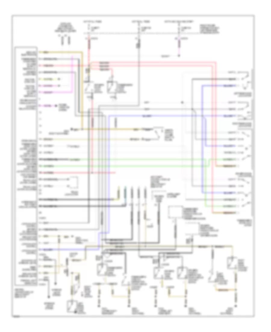
CONVERTIBLE TOP
Convertible Top System Wiring Diagram for BMW 325i 1992

List of elements for Convertible Top System Wiring Diagram for BMW 325i 1992:
- 31e
- Close
- Convertible switch i (in trunk)
- Convertible switch ii (in trunk)
- Convertible top cover motor (in trunk)
- Convertible top motor (in trunk)
- Convertible top switch
- Cover micro switch close (in trunk)
- Cover micro switch open (in trunk)
- Dead point micro switch (right side of windshield header)
- Electro- mechanical convertible top control unit (in trunk)
- Fuse 15a
- Fuse 30a
- Fuse 7.5a
- G201 (right side of i/p)
- G408 (in trunk)
- Hot at all times
- Hot in accy, run or start
- Instrument cluster
- Interior lights system
- Open
- Power distribution box (left rear corner of engine compt.)
- S5 open
- S6 close
- Speed in
- Speed out
COOLING FAN
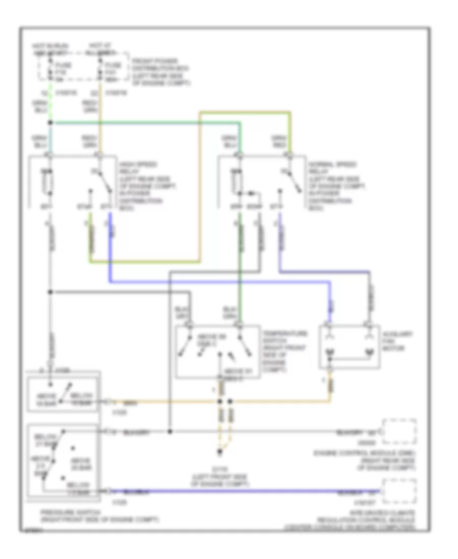
Auxiliary Cooling Fan Wiring Diagram, Convertible for BMW 325i 1992
List of elements for Auxiliary Cooling Fan Wiring Diagram, Convertible for BMW 325i 1992:
- A/c input
- A/c request input
- A/c select switch
- Auxiliary fan (in front of radiator)
- Auxiliary fan normal speed blower resistor (6 ohms) (in front of radiator, left side of auxiliary fan)
- C114
- Closed above o 196 f o (91 c)
- Closed above o 210 f o (99 c)
- Control switches
- Diode
- Dual temperature switch (top right side of radiator)
- Evaporator temperature regulator (on left side of evaporator housing)
- Fuse 18 30a
- Fuse 19 7.5a
- Fuse 20 30a
- Fuse 3 15a
- G106 (on inner fender, behind left headlight)
- G202 (behind left side of dash, above brake pedal)
- Hot at all times
- Hot in run only from unloader relay k7
- K1 normal speed relay
- K6 high speed relay
- Motronic control unit (behind right side of dash, above glove box)
- Off
- Power distribution box (left rear corner of engine compartment)
- Red
- Some vehicles use an additional splice (s325). see ground distribution for details.
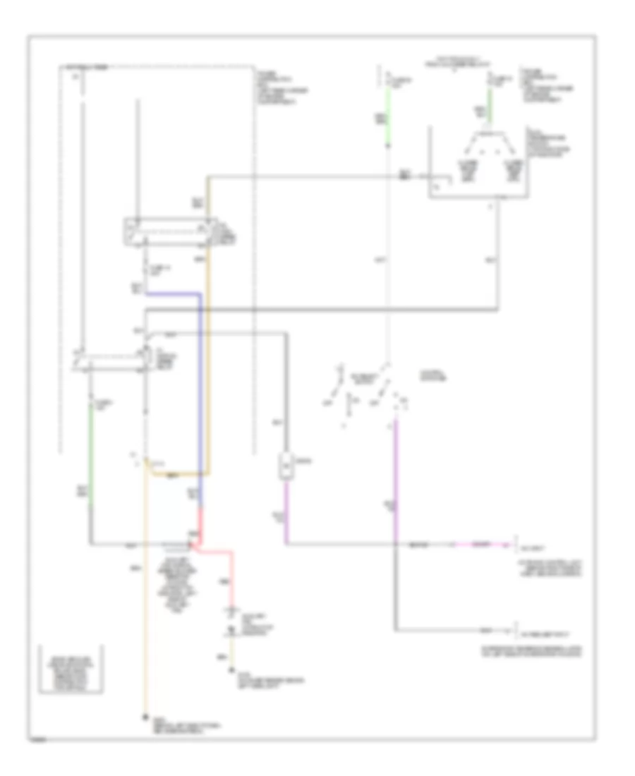
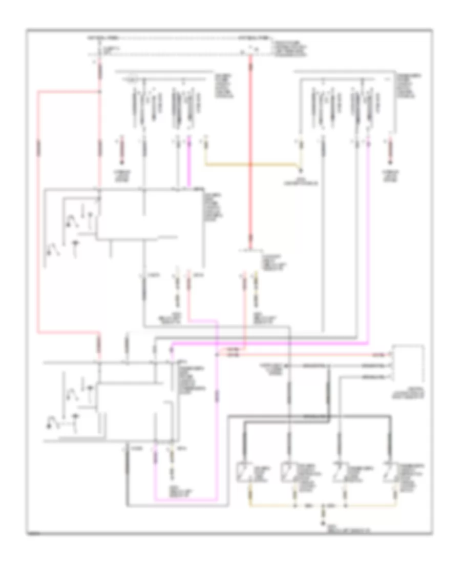
Auxiliary Cooling Fan Wiring Diagram, Except Convertible for BMW 325i 1992
List of elements for Auxiliary Cooling Fan Wiring Diagram, Except Convertible for BMW 325i 1992:
- 85b
- 87a
- Above 18 bar
- Above 2.6 bar
- Above 30 bar
- Above 91 deg c
- Above 99 deg c
- Auxiliary fan motor
- Below 1.5 bar
- Below 15 bar
- Below 21 bar
- Engine control module (dme) (right rear side of engine compt)
- Front power distribution box (left rear side of engine compt)
- Fuse f16 5a
- Fuse f41 30a
- G110 (left front side of engine compt)
- High speed relay (left rear side of engine compt, in power distribution box)
- Hot at all times
- Hot in run and start
- Integrated climate regulation control module (center console on board computer)
- Normal speed relay (left rear side of engine compt, in power distribution box)
- Pressure switch (right front side of engine compt)
- Temperature switch (right front side of engine compt)
- X10016
- X10018
- X126
- X18157
- X6000
DEFOGGERS
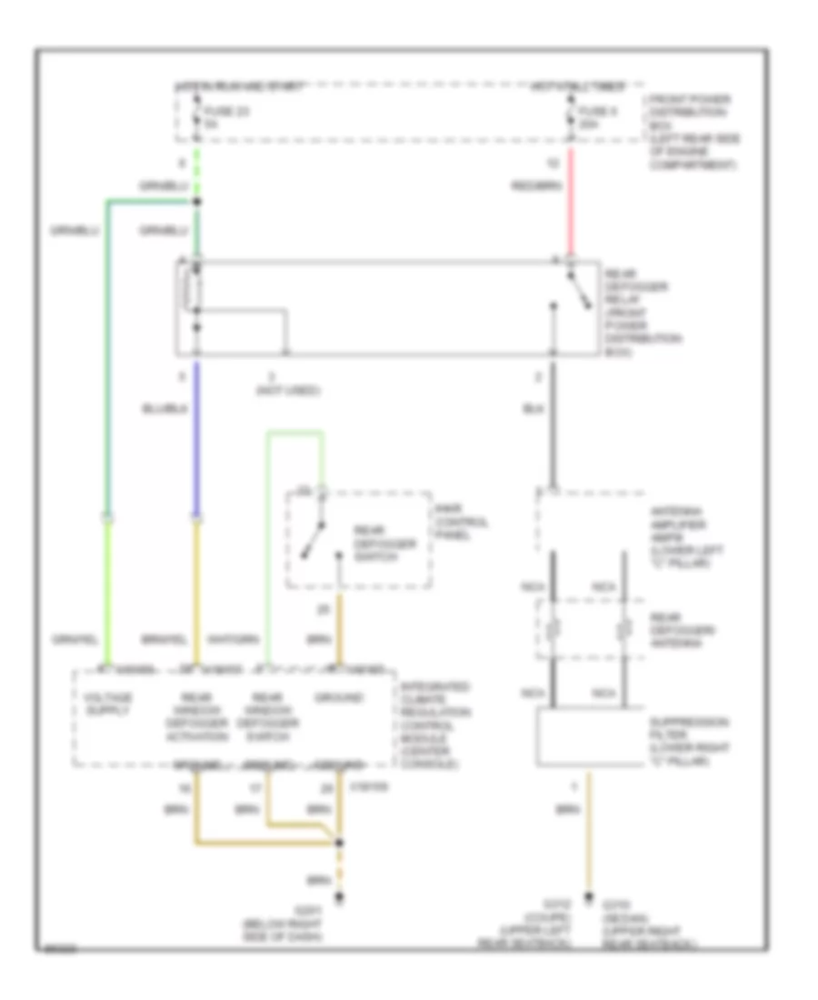
Defogger Wiring Diagram for BMW 325i 1992
List of elements for Defogger Wiring Diagram for BMW 325i 1992:
- (not used)
- Antenna amplifier am/fm (lower left "c" pillar)
- Front power distribution box (left rear side of engine compartment)
- Fuse 23 5a
- Fuse 6 20a
- G201 (below right side of dash)
- G310 (sedan) (upper right rear seatback)
- G312 (coupe) (upper left rear seatback)
- Ground
- Hot at all times
- Hot in run and start
- Ihkr control panel
- Integrated climate regulation control module (center console)
- Nca
- Rear defogger relay (front power distribution box)
- Rear defogger switch
- Rear defogger/ antenna
- Rear window defogger activation
- Rear window defogger switch
- Suppression filter (lower right "c" pillar)
- X18155
- X18156
- X18157
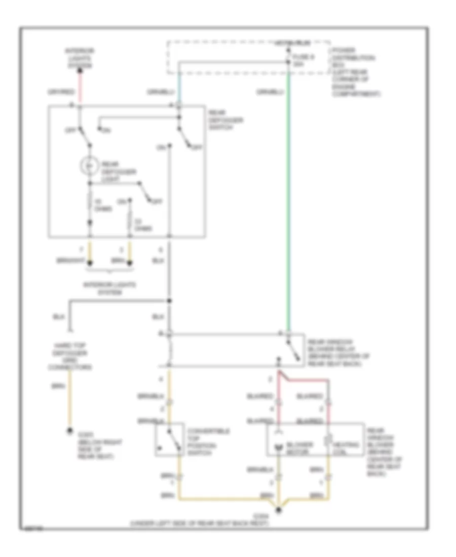
Defogger Wiring Diagram, Convertible for BMW 325i 1992
List of elements for Defogger Wiring Diagram, Convertible for BMW 325i 1992:
- Blower motor
- Convertible top position switch
- Fuse 8 30a
- G303 (below right side of rear seat)
- G304 (under left side of rear seat back rest)
- Hard top defogger grid connectors
- Heating coil
- Hot in run
- Interior lights system
- Off
- Ohms
- Power distribution box (left rear corner of engine compartment)
- Rear defogger light
- Rear defogger switch
- Rear window blower (behind center of rear seat back)
- Rear window blower relay (behind center of rear seat back)
HORN
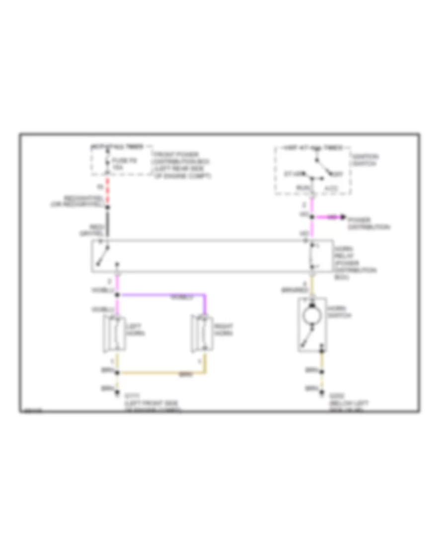
Horn Wiring Diagram for BMW 325i 1992
List of elements for Horn Wiring Diagram for BMW 325i 1992:
- Acc
- Front power distribution box (left rear side of engine compt)
- Fuse f8 15a
- G111 (left front side of engine compt)
- G202 (below left side of i/p)
- Horn relay (power distribution box)
- Horn switch
- Hot at all times
- Ignition switch
- Left horn
- Off
- Power distribution
- Right horn
- Run
- Start
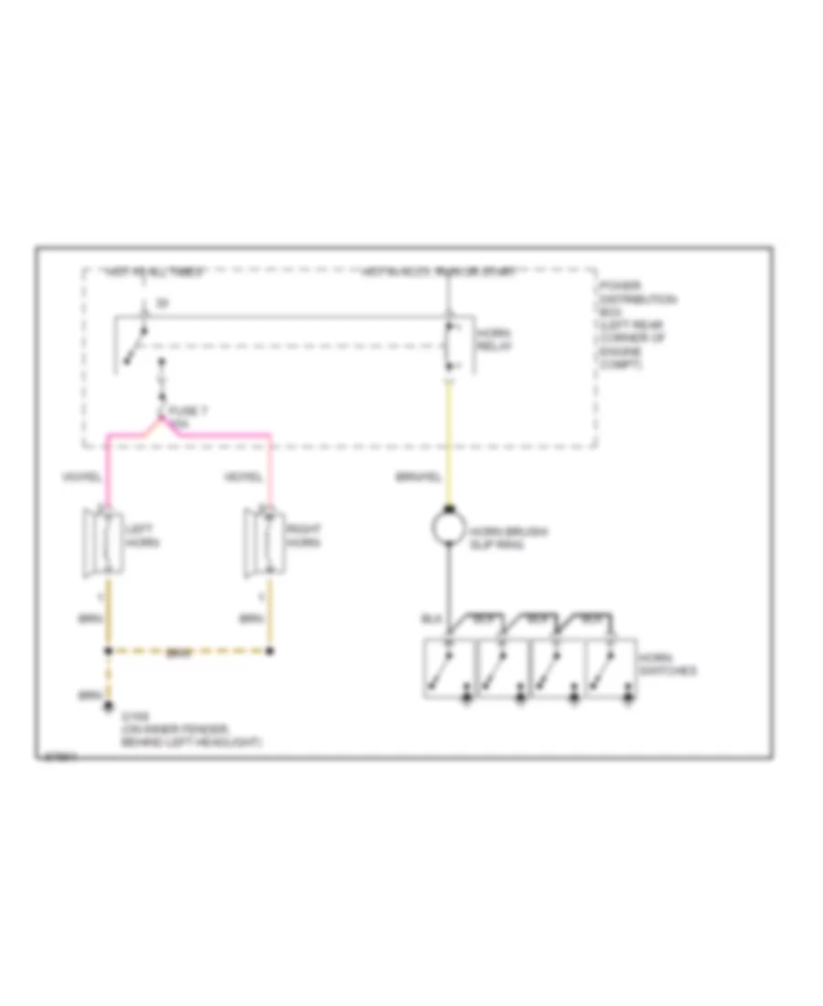
Horn Wiring Diagram, Convertible for BMW 325i 1992
List of elements for Horn Wiring Diagram, Convertible for BMW 325i 1992:
- Fuse 7 15a
- G106 (on inner fender, behind left headlight)
- Horn brush/ slip ring
- Horn relay
- Horn switches
- Hot at all times
- Hot in accy, run or start
- Left horn
- Power distribution box (left rear corner of engine compt)
- Right horn
POWER ANTENNA
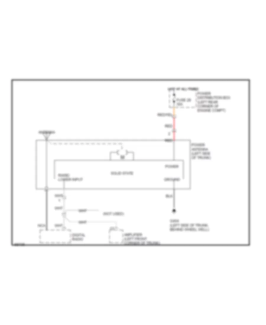
Power Antenna Wiring Diagram for BMW 325i 1992
List of elements for Power Antenna Wiring Diagram for BMW 325i 1992:
- (not used)
- Amplifier (left front corner of trunk)
- Antenna
- Digital radio
- Fuse 28 30a
- G404 (left side of trunk, behind wheel well)
- Ground
- Hot at all times
- Nca
- Power
- Power antenna (left side of trunk)
- Power distribution box (left rear corner of engine compt)
- Raise/ lower input
- Red
- Solid state
POWER DOOR LOCKS
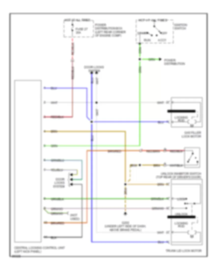
Power Door Lock Wiring Diagram, Convertible for BMW 325i 1992
List of elements for Power Door Lock Wiring Diagram, Convertible for BMW 325i 1992:
- (not used)
- Accy
- Automatic unlock request
- Central locking control unit (left kick panel)
- Driver's door lock motor
- Fuse 27 30a
- G202 (under left side of dash, above brake pedal)
- Gas filler lock motor
- Ground
- Hot at all times
- Ignition switch
- Inertia switch
- Lock
- Lock control
- Lock request input
- Locking rod
- Off
- Power distribution
- Power distribution box (left rear corner of engine compt)
- Power input
- Right front door lock motor
- Right front door micro switch
- Run
- Saftey catch button
- Start
- Trunk lid lock motor
- Unlock
- Unlock control
- Unlock inhibit request input
- Unlock inhibit switch
- Unlock request input
Power Door Lock Wiring Diagram, Except Convertible for BMW 325i 1992
List of elements for Power Door Lock Wiring Diagram, Except Convertible for BMW 325i 1992:
- 2 door
- 4 door
- 4 door
- 4 door only
- Activation of interior lights
- Alpine
- Anti-theft control module (alpine) (below right side of i/p)
- Battery voltage for zv motor drive
- Central locking module (below right side of i/p)
- Comfort relay control
- Crash signal
- Data link connector (back of right side shock tower)
- Driver's door handle switch
- Driver's door jamb switch
- Driver's door lock motor
- Driver's door lock switch
- Driver's door open
- Driver's side power window module (2 door) (driver's door)
- Driver's window retraction door handle contact switch
- Exterior lights system
- Front power distribution box (left rear side of engine compt)
- Fuse f35 25a
- Fuse f43 5a
- Fuse f7 5a
- G203 (right kick panel)
- G310 (upper right rear seat)
- G312 (upper left rear seat)
- Ground for interior lights
- Ground for zv motor drive
- Ground, electronics
- Hot at all times
- Hot in acc, run and start
- Inertia switch (lower right "a" pillar)
- Instrument cluster
- Interface to anti-theft module (alpine)
- Interior lights system
- Left rear door contact (4 door)
- Left rear door jamb switch
- Left rear door lock motor
- Lock contact for arrest
- Lock/unlock control
- Nca
- Parking light detection
- Passenger's door jamb switch
- Passenger's door lock motor
- Passenger's door lock motor locked driver's door lock motor locked
- Passenger's door lock motor unlocked driver's door lock motor unlocked
- Passenger's door lock switch
- Passenger's side power window module (2 door) (passenger's door)
- Passenger's window retraction door handle contact switch
- Power windows system
- Rear doors open
- Red/
- Right rear door contact (4 door)
- Right rear door jamb switch
- Right rear door lock motor
- Rxd diag. data link
- Trunk lock motor
- Trunk lock motor locked
- Trunk lock motor unlocked
- Txd diag. data link
- W/o alpine
- X10015
- X10018
- X13012
- X13013
- X13014
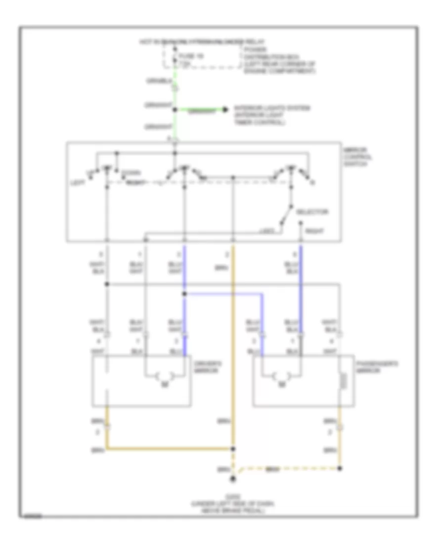
POWER MIRRORS
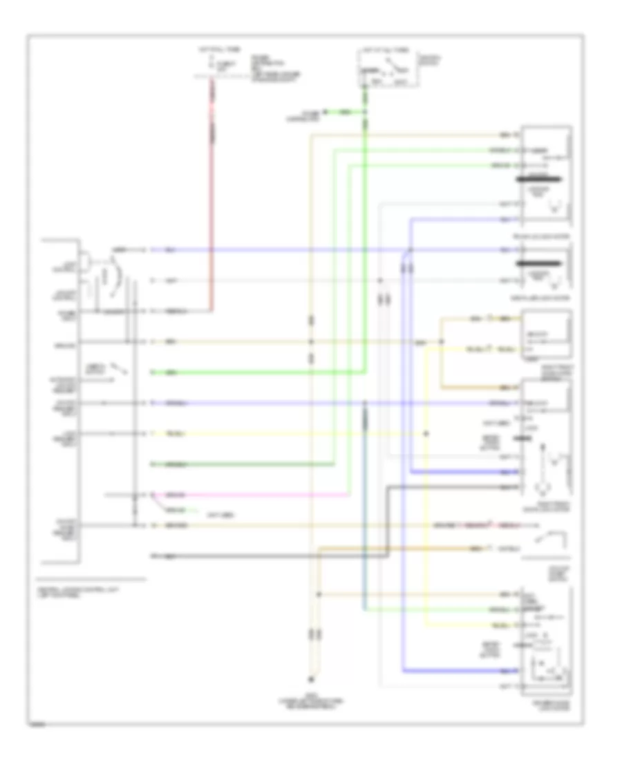
Power Mirror Wiring Diagram, Convertible for BMW 325i 1992
List of elements for Power Mirror Wiring Diagram, Convertible for BMW 325i 1992:
- Down
- Driver's mirror
- Fuse 19 7.5a
- G202 (under left side of dash, above brake pedal)
- Hot in run only from unloader relay
- Interior lights system (interior light timer control)
- Left
- Mirror control switch
- Off
- Passenger's mirror
- Power distribution box (left rear corner of engine compartment)
- Right
- Selector
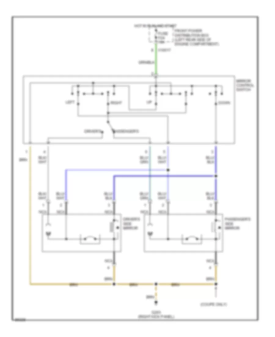
Power Mirror Wiring Diagram, Except Convertible for BMW 325i 1992
List of elements for Power Mirror Wiring Diagram, Except Convertible for BMW 325i 1992:
- (coupe only)
- Down
- Driver's
- Driver's side mirror
- Front power distribution box (left rear side of engine compartment)
- Fuse f24 10a
- G203 (right kick panel)
- Hot in run and start
- Left
- Mirror control switch
- Nca
- Passenger's
- Passenger's side mirror
- Right
- X10017
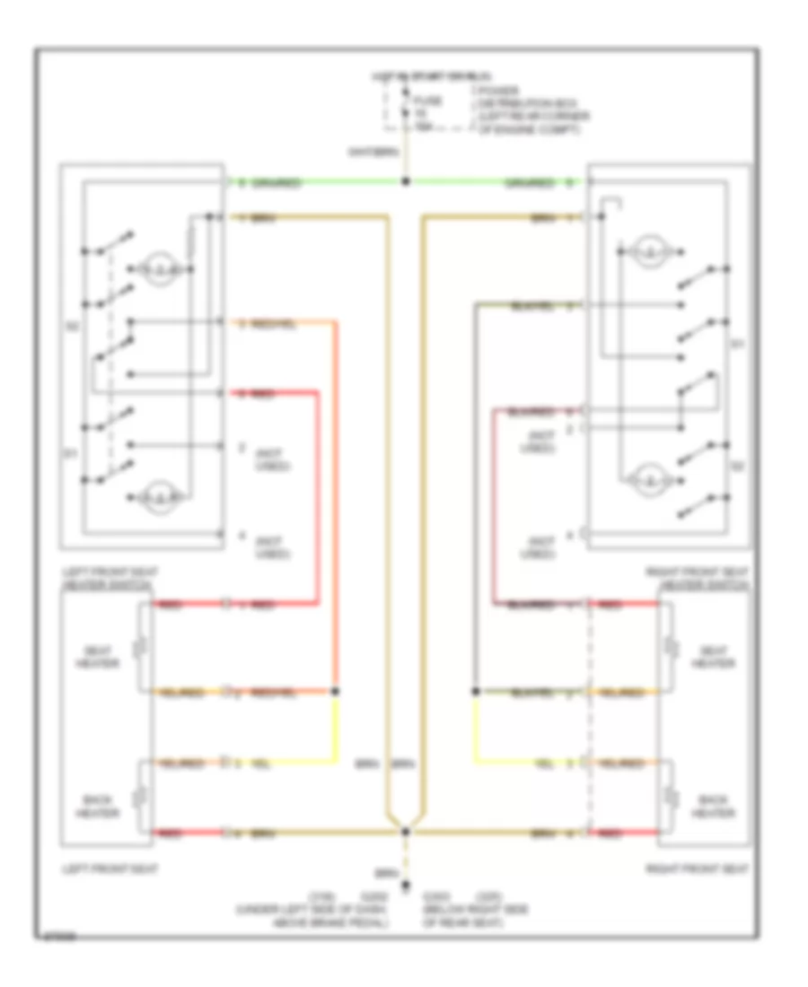
POWER SEATS
Heated Seats Wiring Diagram, Convertible for BMW 325i 1992
List of elements for Heated Seats Wiring Diagram, Convertible for BMW 325i 1992:
- (318)
- (325)
- (not used)
- Back heater
- Fuse 15a
- G202 (under left side of dash, above brake pedal)
- G303 (below right side of rear seat)
- Hot in start or run
- Left front seat
- Left front seat heater switch
- Power distribution box (left rear corner of engine compt)
- Red
- Right front seat
- Right front seat heater switch
- Seat heater
Heated Seats Wiring Diagram, Except Convertible for BMW 325i 1992
POWER WINDOWS
Power Window Wiring Diagram, 2 Door Except Convertible for BMW 325i 1992
List of elements for Power Window Wiring Diagram, 2 Door Except Convertible for BMW 325i 1992:
- Central locking module (right side of i/p)
- Close auto
- Comfort relay (below left side of i/p)
- Driver's door jamb switch
- Driver's power window switch (center console)
- Driver's side power window module (driver's door)
- Driver's window retraction door handle contact switch
- Front power distribution box (left rear side of engine compt)
- Fuse f14 30a
- G202 (below left side of i/p)
- G302 (center console)
- Hot at all times
- Instrument cluster system
- Interior lights system
- Off
- Open auto
- Passenger's door jamb switch
- Passenger's power window switch (center console)
- Passenger's side power window module (passenger's door)
- Passenger's window retraction door handle contact switch
- Red
- Window closed
- Window open
- Window open off
- X18279
- X18280
- X9744
- X9749
Power Window Wiring Diagram, 4 Door for BMW 325i 1992
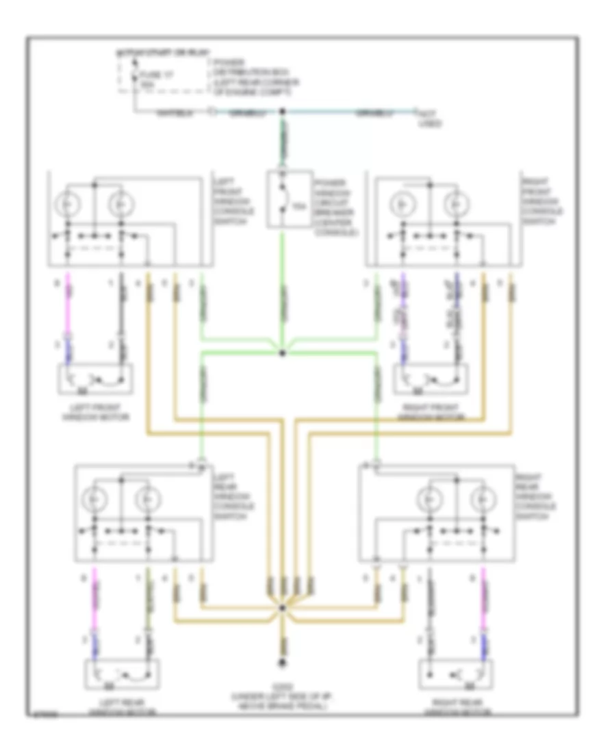
Power Window Wiring Diagram, Convertible for BMW 325i 1992
List of elements for Power Window Wiring Diagram, Convertible for BMW 325i 1992:
- 15a
- Fuse 17 30a
- G202 (under left side of i/p, above brake pedal)
- Hot in start or run
- Left front window console switch
- Left front window motor
- Left rear window console switch
- Left rear window motor
- Not used
- Power distribution box (left rear corner of engine compt)
- Power window circuit breaker (center console)
- Right front window console switch
- Right front window motor
- Right rear window console switch
- Right rear window motor
RADIO
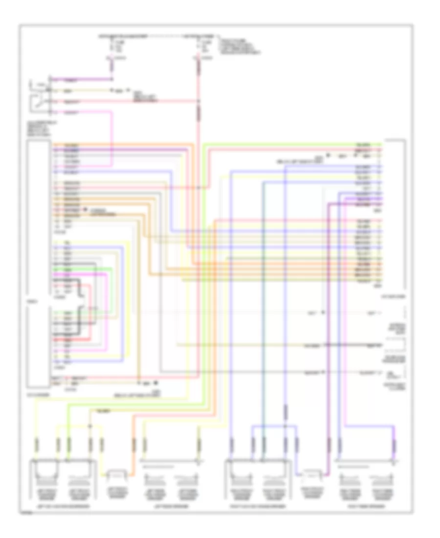
10-Speaker System Wiring Diagram for BMW 325i 1992
List of elements for 10-Speaker System Wiring Diagram for BMW 325i 1992:
- Antenna amplifier am/fm
- Cd changer
- Front power distribution box (left rear side of engine compartment)
- Fuse f44 15a
- Fuse f9 20a
- G202 (below left side of dash)
- Hifi amplifier
- Hot at all times
- Hot in accy, run and start
- Instrument cluster
- Interior lights system
- Left front high range speaker
- Left front low range speaker
- Left front midrange speaker
- Left mid-high range speaker
- Left rear high range speaker
- Left rear low range speaker
- Left rear speaker
- Nca
- Radio
- Red
- Right front high range speaker
- Right front low range speaker
- Right front midrange speaker
- Right mid-high range speaker
- Right rear high range speaker
- Right rear low range speaker
- Right rear speaker
- Telephone transceiver
- Unloader relay terminal r (below left side of dash)
- Vss output
- X10015
- X10018
- X18126
- X18180
- X18520
- X18521
- X605
- X606
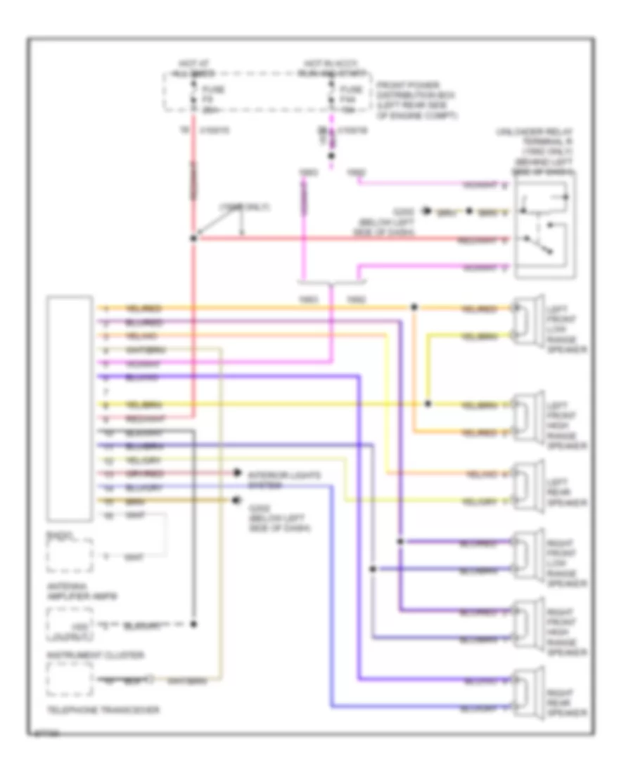
6-Speaker System Wiring Diagram for BMW 325i 1992
List of elements for 6-Speaker System Wiring Diagram for BMW 325i 1992:
- (1992 only)
- Antenna amplifier am/fm
- Front power distribution box (left rear side of engine compt)
- Fuse f44 15a
- Fuse f9 20a
- G202 (below left side of dash)
- Hot at all times
- Hot in accy, run and start
- Instrument cluster
- Interior lights system
- Left front high range speaker
- Left front low range speaker
- Left rear speaker
- Radio
- Right front high range speaker
- Right front low range speaker
- Right rear speaker
- Telephone transceiver
- Unloader relay terminal r (1992 only) (behind left side of dash)
- Vss output
- X10015
- X10018
Radio Wiring Diagrams, Convertible for BMW 325i 1992
STARTING/CHARGING
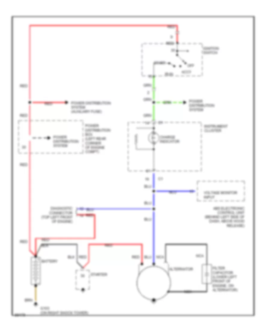
Charging Wiring Diagram, Convertible for BMW 325i 1992
List of elements for Charging Wiring Diagram, Convertible for BMW 325i 1992:
- Abs electronic control unit (behind left side of dash, above hood release)
- Accy
- Alternator
- Battery
- Charge indicator
- Diagnostic connector (top left front of engine)
- Filter capacitor (lower left front of engine, on alternator)
- G103 (on right shock tower)
- Ignition switch
- Instrument cluster
- Nca
- Off
- Power distribution box (left rear corner of engine compt)
- Power distribution system
- Power distribution system (auxiliary fuse)
- Red
- Run
- Start
- Starter
- Voltage monitor input
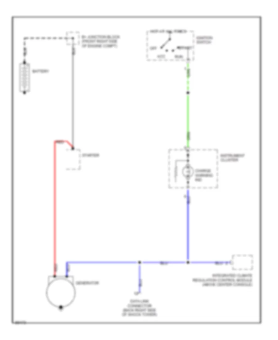
Charging Wiring Diagram, Except Convertible for BMW 325i 1992
List of elements for Charging Wiring Diagram, Except Convertible for BMW 325i 1992:
- Acc
- B+ junction block (front right side of engine compt)
- Battery
- Charge warning ind
- Data link connector (back right side of shock tower)
- Generator
- Hot at all times
- Ignition switch
- Instrument cluster
- Integrated climate regulation control module (above center console)
- Off
- Red
- Run
- Start
- Starter
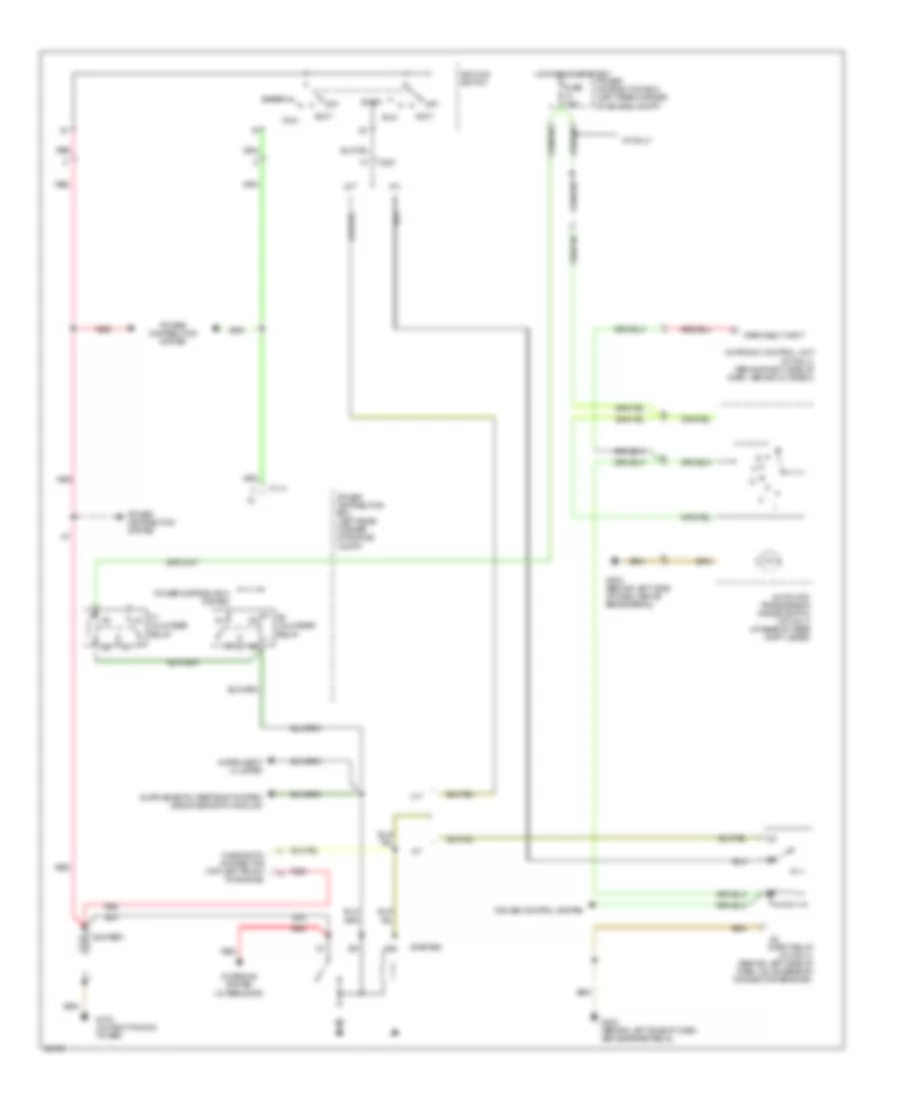
Starting Wiring Diagram, Convertible for BMW 325i 1992
List of elements for Starting Wiring Diagram, Convertible for BMW 325i 1992:
- 30h
- A/t
- A/t only
- Accy
- Automatic transmission range switch (a/t only) (at base of gear shift lever)
- Battery
- C114
- C200
- Charging system (alternator)
- Cruise control system
- Diagnostic connector (top left front of engine)
- Fuse 7.5a
- G103 (on right shock tower)
- G202 (behind left side of dash, above brake pedal)
- Hot in run or start
- Ignition switch
- Instrument cluster
- K5 unloader relay
- K7 unloader relay
- M/t
- Motronic control unit (a/t only) (behind right side of dash, above glove box)
- Off
- Park/neut input
- Power distribution box (left rear corner of engine compt)
- Power distribution system
- Red
- Run
- Start
- Start relay (a/t only) (behind left side of dash, on accessory connector bracket)
- Starter
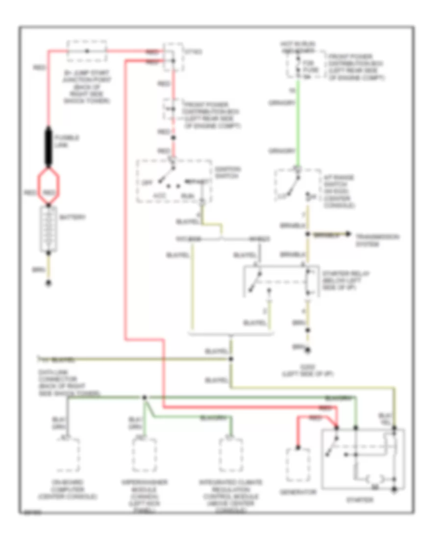
Starting Wiring Diagram, Except Convertible for BMW 325i 1992
List of elements for Starting Wiring Diagram, Except Convertible for BMW 325i 1992:
- A/t range switch (w/ egs) (center console)
- Acc
- B+ jump start junction point (back of right side shock tower)
- Battery
- Data link connector (back of right side shock tower)
- F28 fuse 5a
- Front power distribution box (left rear side of engine compt)
- Fusible link
- G202 (left side of i/p)
- Generator
- Hot in run and start
- Ignition switch
- Integrated climate regulation control module (above center console)
- Off
- On-board computer (center console)
- Red
- Run
- Start
- Starter
- Starter relay (below left side of i/p)
- Transmission system
- W/ egs
- W/o egs
- Wiper/washer module (canada) (left kick panel)
- X7163
TRUNK, TAILGATE, FUEL DOOR
Trunk, Tailgate, Fuel Door Wiring Diagrams, Convertible for BMW 325i 1992
List of elements for Trunk, Tailgate, Fuel Door Wiring Diagrams, Convertible for BMW 325i 1992:
- (not used)
- Accy
- Central locking control unit (left kick panel)
- Door locks system
- Fuse 27 30a
- G202 (under left side of dash, above brake pedal)
- Gas filler lock motor
- Hot at all times
- Ignition switch
- Lock
- Locking rod
- Off
- Power distribution
- Power distribution box (left rear corner of engine comp)
- Run
- Start
- Trunk lid lock motor
- Unlock
- Unlock inhibitor switch (top rear of driver's door)
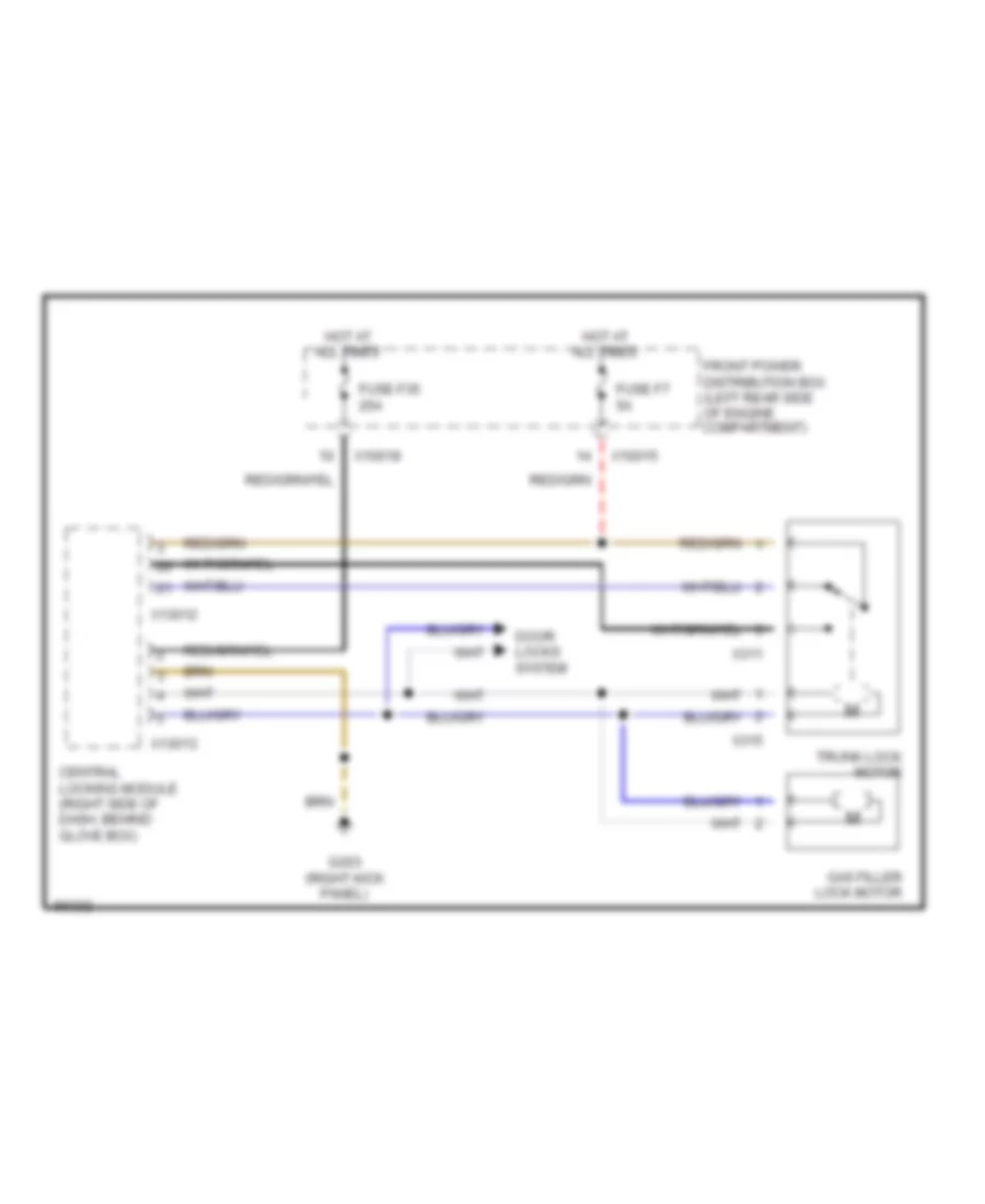
Trunk, Tailgate, Fuel Door Wiring Diagrams, Except Convertible for BMW 325i 1992
List of elements for Trunk, Tailgate, Fuel Door Wiring Diagrams, Except Convertible for BMW 325i 1992:
- Central locking module (right side of dash, behind glove box)
- Door locks system
- Front power distribution box (left rear side of engine compartment)
- Fuse f35 25a
- Fuse f7 5a
- G203 (right kick panel)
- Gas filler lock motor
- Hot at all times
- Trunk lock motor
- X10015
- X10018
- X13012
- X13013
- X311
- X315
WIPER/WASHER
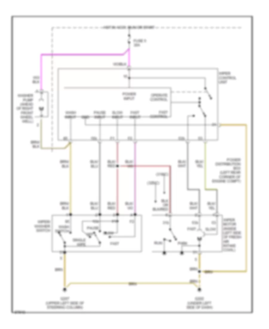
Wiper/Washer Wiring Diagram, Convertible for BMW 325i 1992
List of elements for Wiper/Washer Wiring Diagram, Convertible for BMW 325i 1992:
- (318ic)
- (325ic)
- 15b
- 31b
- 53b
- Fast
- Fast control
- Fast input
- Fuse 5 30a
- G202 (under left side of dash)
- G207 (upper left side of steering column)
- Gnd
- Hot in accy, run or start
- Off
- Operate control
- Park
- Pause
- Pause input
- Power distribution box (left rear corner of engine compt)
- Power input
- Run
- Single wipe
- Slow
- Slow input
- Wash input
- Wash switch
- Washer pump (ahead of right front wheel well)
- Wiper control unit
- Wiper motor (inside left side of fresh air intake cowl)
- Wiper/ washer switch
Wiper/Washer Wiring Diagram, USA for BMW 325i 1992
Wiper/Washer/Headlamp Washer Wiring Diagram, Canada for BMW 325i 1992