Diagram sections — 32 (56 total)
AIR CONDITIONING ANTI-LOCK BRAKES ANTI-THEFT BODY COMPUTER COMPUTER DATA LINES COOLING FAN CRUISE CONTROL DEFOGGERS ELECTRONIC POWER STEERING ELECTRONIC SUSPENSION ENGINE PERFORMANCE EXTERIOR LIGHTS GROUND DISTRIBUTION HEADLIGHTS HORN INSTRUMENT CLUSTER INTERIOR LIGHTS MEMORY SYSTEMS POWER DISTRIBUTION POWER DOOR LOCKS POWER MIRRORS POWER SEATS POWER TOP/SUNROOF POWER WINDOWS RADIO SHIFT INTERLOCKS STARTING/CHARGING SUPPLEMENTAL RESTRAINTS TRANSMISSION TRUNK, TAILGATE, FUEL DOOR WARNING SYSTEMS WIPER/WASHER
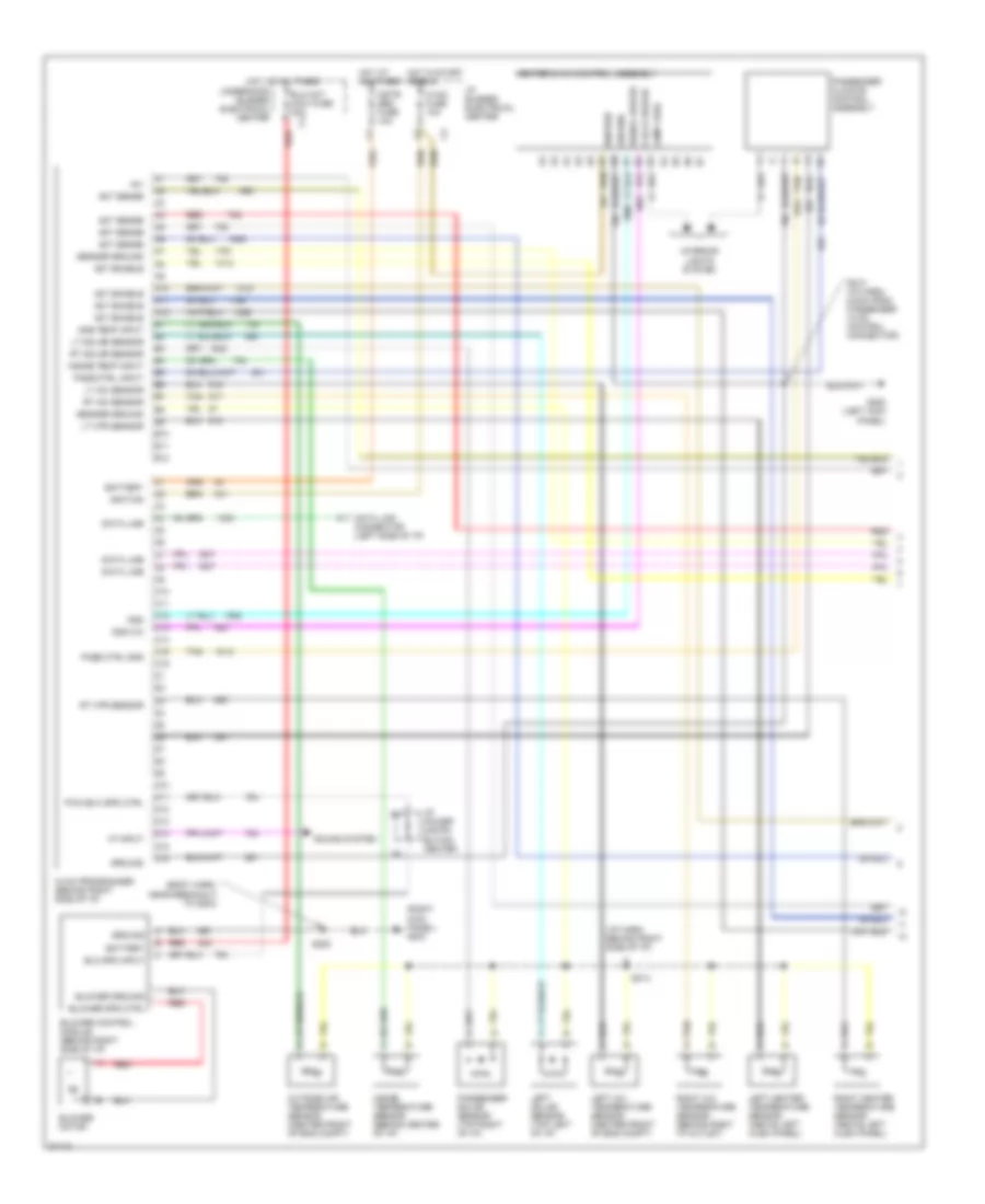
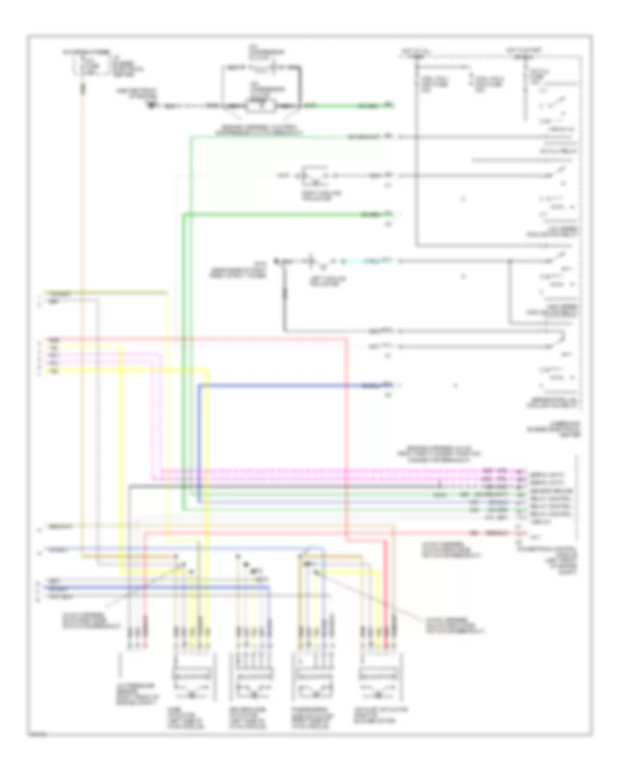
AIR CONDITIONING Air Conditioning Wiring Diagrams (1 of 2) for Buick Park Avenue Ultra 1997 List of elements for Air Conditioning Wiring Diagrams (1 of 2) for Buick Park Avenue Ultra 1997: 81 (body harn, near breakout to g203) (i/p harn, behind right side of i/p) (right kick panel) g203 +5v A10 A11 A12 Act enable Act sense Amb temp input B10 B11 B12 Battery Blo mot maxi fuse 30a Blo spd input Blower control module (behind right side of i/p) Blower ground Blower motor Blower spd ctrl C10 C11 C12 C13 C14 C15 C16 Clock driver Cstr/ sbm fuse 10a D10 D11 D12 D13 D14 D15 D16 Data line Data link connector (left side of i/p) G200 (left kick panel) Ground Heater & a/c control assembly Hot at all times Hot in start or run Hvac fuse 10a Hvac programmer (behind right side of i/p) I/p bussed electrical center I/p power distri- bution center Ignition Inside temp input Inside temperature sensor (behind center of i/p) Interior lights system Kdd Kdd c/k Lamp feed Left a/c temperature sensor (center front of eng compt) Left heater temperature sensor (above left hush panel) Left solar sensor (top left of i/p) Lt a/c sensor Lt htr sensor Lt solar sensor Outside air temperature sensor (center front of eng compt) Pass ctrl gnd Pass ctrl input Passenger climate control assembly Passenger solar sensor (top right of i/p) Pwm blw spd ctrl Red Right a/c temperature sensor (behind right i/p outlet) Right heater temperature sensor (above left hush panel) Rt a/c sensor Rt htr sensor Rt solar sensor S208 S213 (i/p harn, 6.5cm from passenger hvac control connector) S214 Sensor ground Signal driver Sound system Tan Underhood bussed electrical center Vf input Air Conditioning Wiring Diagrams (2 of 2) for Buick Park Avenue Ultra 1997 List of elements for Air Conditioning Wiring Diagrams (2 of 2) for Buick Park Avenue Ultra 1997: 49 (center front of engine) (engine harness, 6 cm from compressor clutch breakout) (engine harness, 6.5 cm from throttle body position connector breakout) (hvac harness, 29 cm from mode actuator breakout) (hvac harness, 33.5 cm from mode actuator breakout) (hvac harness, 50.5 cm from mode actuator breakout) +5 v A/c clu fuse 10a A/c clu relay A/c compressor clutch A/c compressor clutch diode A/c fuse 10a A/c pressure sensor (right front of engine compt) A10 Air inlet actuator (right of blower motor) Cool fan 1 maxi fuse 30a Cool fan 2 maxi fuse 30a D11 Driver's side actuator (left side of hvac module) E10 F11 G103 (near base of right front strut tower) G125 High speed cooling fan relay Hot at all times Hot in start I/p bussed electrical center Left cooling fan motor Low speed cooling fan relay Mode actuator (left side of hvac module) Nca Or run Passenger's side actuator (right side of hvac module) Powertrain control module (left front of engine compt) Red Relay control Right cooling fan motor S103 S106 S107 S274 S275 S278 Sensor ground Serial data Series/parallel cooling fan relay Solid state Underhood bussed electrical center Vsb a/c
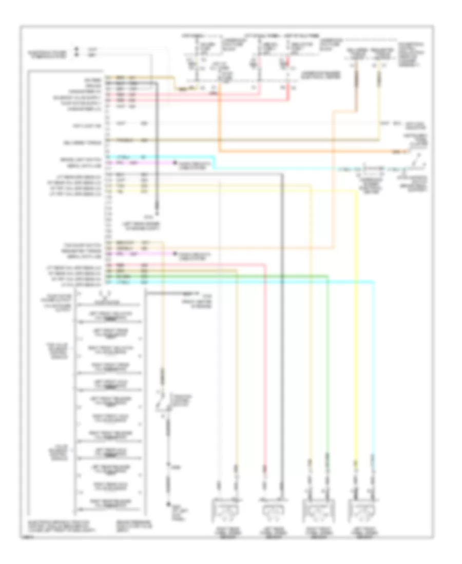
ANTI-LOCK BRAKES Anti-lock Brake Wiring Diagrams for Buick Park Avenue Ultra 1997 List of elements for Anti-lock Brake Wiring Diagrams for Buick Park Avenue Ultra 1997: 71 "anti-lock" ind (front center of engine) (left rear corner of engine compt) A11 Abs motor fuse 1 40a Abs sol fuse 2 40a Antilock indicator B c1 B13 Brake light switch Brake pressure modulator valve (bpmv) C10 Computer data lines system Delivered torque Delivered torque input Electronic brake & traction control module (ebcm/ebtcm) (lower left front of eng compt) Electronic power steering system G104 G125 G200 (at left kick panel) Ground Hot at all times Hot in run Ign feed Ign sen fuse 10a Instrument panel cluster Left front hold valve solenoid Left front isolation valve solenoid Left front prime valve solenoid Left front release valve solenoid Left front wheel speed sensor Left rear hold valve solenoid Left rear release valve solenoid Left rear wheel speed sensor Lf whl spd sens (hi) Lft frt whl spd sens (lo) Lft rear spd sens (hi) Lft rear whl spd sens (lo) Magnasteer (hi) Magnasteer (lo) Nca Powertrain control module (pcm) (near air cleaner assembly) Pump motor Pump motor power output Red Requested torque Requested torque output Right front hold valve solenoid Right front isolation valve solenoid Right front prime valve solenoid Right front release valve solenoid Right front wheel speed sensor Right rear hold valve solenoid Right rear release valve solenoid Right rear wheel speed sensor Rt frt whl spd sens (hi) Rt frt whl spd sens (lo) Rt rear whl spd sens (hi) Rt rear whl spd sens (lo) S299 Serial data line Stop fuse 10a Stoplamp/btsi switch (brake pedal support) Tan Tcs on/off switch Tcs valve solenoid control signals Traction control switch Underhood bussed electrical center Underhood maxi fuse block Valve power output Valve solenoid control signals
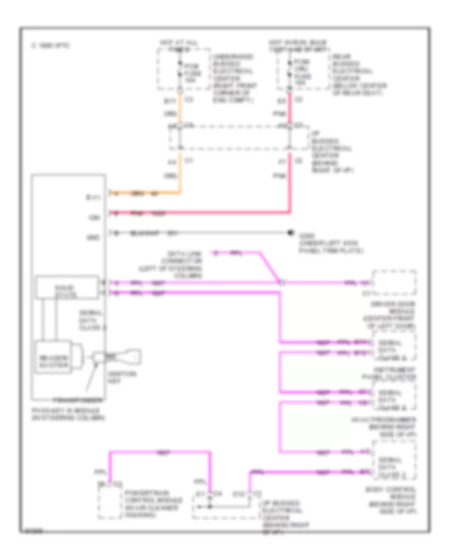
ANTI-THEFT Forced Entry Wiring Diagram for Buick Park Avenue Ultra 1997 List of elements for Forced Entry Wiring Diagram for Buick Park Avenue Ultra 1997: 62 A12 A15 A16 Ajar B (+) B15 B16 C10 Class 2 data line Computer data lines system Disarm/unlock Dome Door lock actuator Driver door module (behind left door trim, center front of door) Driver door switch (in left front door) F11 Fuse 10a G403 (right side of luggage compt, rearward of wheel house) Gnd Hot at all times Hot in run and accy Hot in start and run I/p bussed electrical center (behind right of i/p) Ign Instrument panel cluster Left front door jamb switch (in left front door) Left front door key cylinder switch (in left front door) Left front door lock actuator (in left front door) Left rear door jamb switch (in left front door) Left rear door lock actuator (in left front door) Lf door ajar in Lf door open in Lr door ajar in Lr door open in Mem/ rfa fuse 10a Passenger door module (behind right door trim, center front of door) Pnk Pnk e5 Pnk f5 Rear bussed electrical center (below center of rear seat) Rear door module (right rear of passenger compt, under right rear seat) Red Remote function actuator module (center rear of passenger compt, under rear shelf trim panel) Rf door ajar in Rf door open in Rfarsen Right front door jamb switch (in left front door) Right front door key cylinder switch (in left front door) Right front door lock actuator (in left front door) Right rear door jamb switch (in left front door) Right rear door lock actuator (in left front door) Rr door ajar in Rr door open in S401 Sbmlcm fuse 10a Serial data class 2 Simple bus inter- face Simple bus interface Tan Tell tail in Tell tale out Underhood bussed electrical center (right front corner of eng compt) Pass-Key Wiring Diagram for Buick Park Avenue Ultra 1997 List of elements for Pass-Key Wiring Diagram for Buick Park Avenue Ultra 1997: 28 B (+) B11 B12 Body control module (behind right side of i/p) C 1995 vftc D12 Data link connector (left of steering column) Driver door module (center front of left door) G200 (under left kick panel trim plate) Gnd Hot at all times Hot in run, bulb test and start Hvac programmer (behind right side of i/p) I/p bussed electrical center (behind right of i/p) Ign Ignition key Instrument panel cluster Pass-key iii module (in steering column) Pcm fuse 10a Pcm/ cru fuse 10a Pnk Powertrain control module (in air cleaner housing) Reader/ exciter Rear bussed electrical center (below center of rear seat) Serial data class 2 Solid state Transponder Underhood bussed electrical center (right front corner of eng compt)
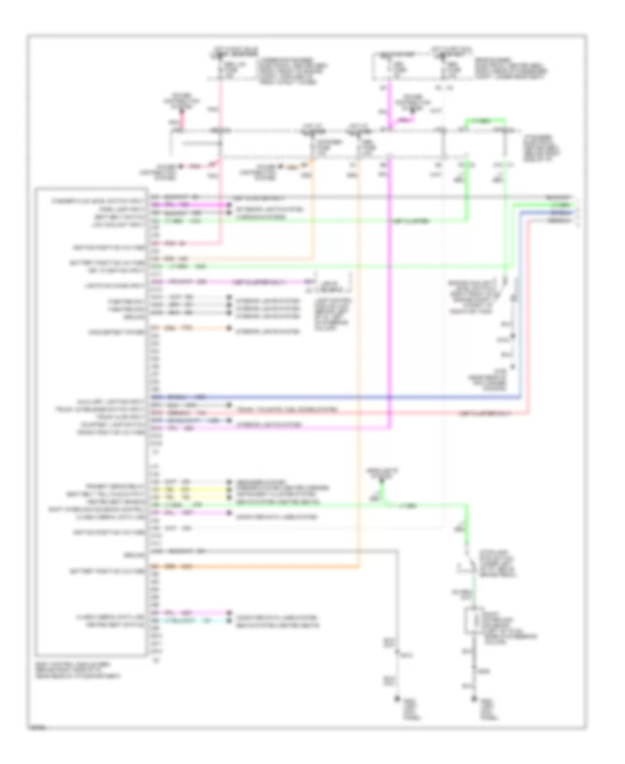
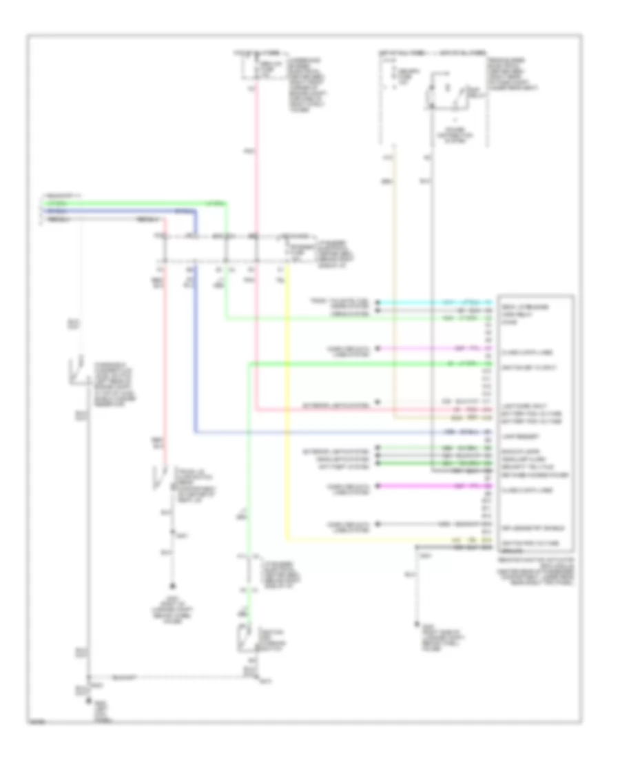
BODY COMPUTER Body Computer Wiring Diagrams (1 of 2) for Buick Park Avenue Ultra 1997 List of elements for Body Computer Wiring Diagrams (1 of 2) for Buick Park Avenue Ultra 1997: 84 (ub7 cluster only) (ub7 cluster) A10 A11 A12 Auxiliary lighting input B10 B10 c3 B11 B12 Battery positive voltage Body control module (sbm) (behind right side of i/p, near rear of i/p compartment) C1 d10 C10 C11 C12 C13 C14 C15 C16 C2 f6 Class 2 serial data line Computer data lines system Courtesy lamp switch Crank positive voltage Crk fuse 5a Cstr/sbm fuse 10a D10 D11 D12 D13 D14 D15 D16 Defogger system, mirrors system (heated mirrors) E5 c3 Engine coolant level switch (right front of engine compt, in right of radiator tank) Exterior lights system F5 c3 G106 (near rear of air cleaner housing) G200 (left kick panel) Ground Headlights system Heated seat enable Heated seat status Hot at all times Hot in off, run or start Hot in run, bulb test, or start Hot in start I/p bussed electrical center (bec) (behind right side of i/p) Ignition positive voltage Inadvertent power Instrument cluster system Interior lights system Key in ignition input Lamp control module (lcm) (behind left of i/p, left of steering column) Lights on chime input Lights on input Low coolant input Park lamp input Pnk Power distribution system Primery defog relay Rear bussed electrical center (bec) (right rear of passenger compt, under rear seat) S102 S205 S213 Sbm fuse 10a Sbm fuse 15a Sbm lcm fuse 10a Seat belt switch Seat belt telltale output Seats system (heated seats) Shift interlock solenoid (left of i/p on base of steeering column) Shift interlock solenoid control Stoplamp/ btsi switch (under left of i/p, above brake pedal) Theatre dim1 Theatre dim2 Trunk ajar input Trunk lid release switch input Trunk, tailgate, fuel doors system Underhood bussed electrical center (bec) (right front of engine compt, forward of front strut tower) Warning systems Washer fluid level switch input Body Computer Wiring Diagrams (2 of 2) for Buick Park Avenue Ultra 1997 List of elements for Body Computer Wiring Diagrams (2 of 2) for Buick Park Avenue Ultra 1997: 58 A10 A11 A12 A13 A14 A15 A16 Anti-theft system B10 B11 B12 B13 B14 B15 B16 Backup lamps Battery pos voltage C4 b1 Chime Class 2 data lines Computer data lines system Deck lid release Exterior lights system F10 F11 G200 (left kick panel) G403 (right of luggage compt, behind wheel house) G403 (right side of luggage compt, behind whell house) Ground Headlamp alarm Headlights system Horn relay Horns system Hot at all times Hot in acc I/p bussed electrical center (bec) (behind right side of i/p) Ignition key in input Ignition key warning switch Ignition pos voltage Keyless entry enable Lamp request Light/dark input Mem/rfa fuse 10a Pnk Power distribution system Rap relay Rear bussed electrical center (bec) (right rear of pass compt, under rear seat) Remote function actuator (rfa) module (center rear of passenger compartment, under rear rear shelf trim panel) Retained access power Rfarsen fuse 10a S213 S401 Sbm/lcm fuse 10a Security telltale Trunk lid ajar switch (rear compartment, on center of deck lid) Trunk, tailgate, fuel doors system Underhood bussed electrical center (bec) (right front corner of engine compt, forward of front strut tower) Windshield washer fluid level switch (left rear of engine compt, in top of wind- shield washer reservoir)
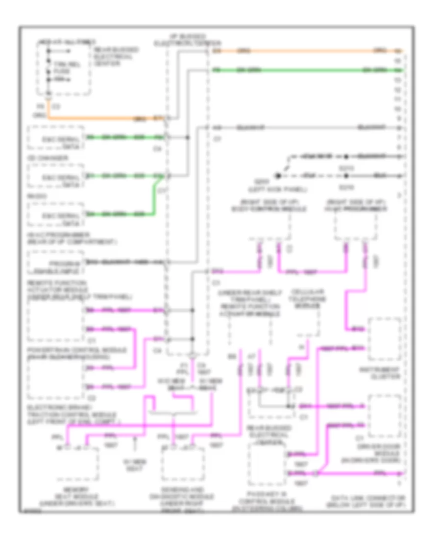
COMPUTER DATA LINES Computer Data Lines for Buick Park Avenue Ultra 1997 List of elements for Computer Data Lines for Buick Park Avenue Ultra 1997: 35 (left kick panel) (right side of i/p) body control module (right side of i/p) hvac programmer (under rear shelf trim panel) remote function actuator module A7 c2 B11 B12 B13 program enable input C4 e&c serial data Cd changer Cellular telephone module D11 D12 Data link connector (below left side of i/p) Driver door module (in driver's door) E&c serial data E1 e&c serial data Electronic brake/ traction control module (left front of eng. compt.) G200 Hot at all times Hvac programmer (rear of i/p compartment) I/p bussed electrical center Instrument cluster Memory seat module (under driver's seat) Pass-key iii control module (in steering column) Powertrain control module (in air cleaner housing) Radio Rear bussed electrical center Remote function actuator module (under rear shelf trim panel) S210 S213 Sensing and diagnostic module (under right front seat) Trk rel fuse 10a W/ mem seat W/o mem seat
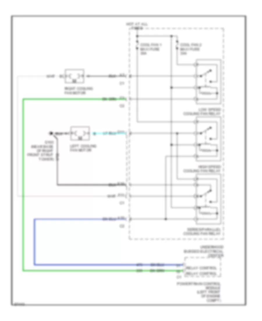
COOLING FAN Cooling Fan Wiring Diagram for Buick Park Avenue Ultra 1997 List of elements for Cooling Fan Wiring Diagram for Buick Park Avenue Ultra 1997: 16 A10 Cool fan 1 maxi fuse 30a Cool fan 2 maxi fuse 30a D11 E10 F11 G103 (near base of right front strut tower) High speed cooling fan relay Hot at all times Left cooling fan motor Low speed cooling fan relay Powertrain control module (left front of engine compt) Relay control Right cooling fan motor Series/parallel cooling fan relay Underhood bussed electrical center
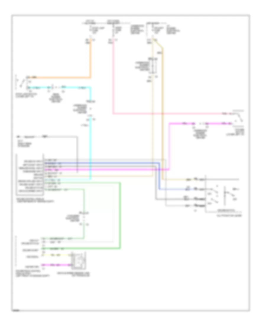
CRUISE CONTROL Cruise Control Wiring Diagram for Buick Park Avenue Ultra 1997 List of elements for Cruise Control Wiring Diagram for Buick Park Avenue Ultra 1997: 40 (center rear of engine compt) All times B12 C10 Cr cont fuse 10a Cruise control module Cruise inhibit Cruise inhibit input Cruise on input Cruise status Cruise switch Disengage input G117 (right rear of engine) Ground Hot at Hot in run Hot in run and start I/p bussed electrical center Ignfd fuse 2a Ignition Multifunction lever Nca Off Pnk Powertrain control module (pcm) (left front of engine compt) R/a Rear bussed electrical center Resume/accel input S/c S108 Set/coast input Stop lamp fuse 10a Stop lamp switch (lower left i/p) Tcc/abs switch (lower left i/p) Underhood bussed electrical center Vehicle speed input Vehicle speed sensor (vss) (on transaxle) Vss out Vss return Vss signal
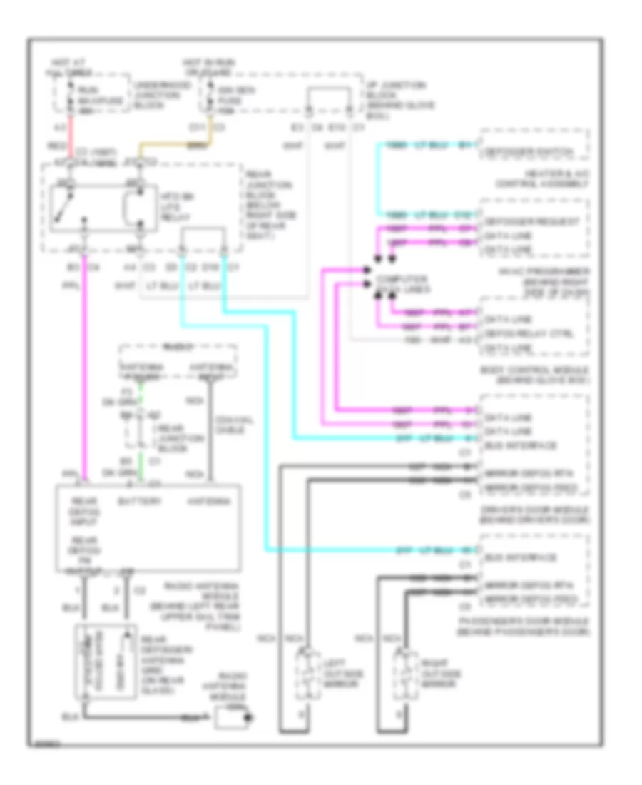
DEFOGGERS Defogger Wiring Diagram for Buick Park Avenue Ultra 1997 List of elements for Defogger Wiring Diagram for Buick Park Avenue Ultra 1997: 48 (1997) (1998) A4 c3 Am grid Antenna Antenna input Antenna power B3 c4 Battery Body control module (behind glove box) Bus interface C11 c3 C12 C3 f3 Coaxial cable Computer data lines D10 c1 D3 c2 Data line Defog relay ctrl Defogger request Defogger switch Driver's door module (behind driver's door) E10 c1 E3 c4 Heater & a/c control assembly Hot at all times Hot in run or start Htd bk lite relay Hvac programmer (behind right side of dash) I/p junction block (behind glove box) Ign sen fuse 10a Left outside mirror Mirror defog feed Mirror defog rtn Nca Passenger's door module (behind passenger's door) Radio Radio antenna module (behind left rear upper sail trim panel) Radio antenna module coil Rear defog input Rear defog/ fm output Rear defogger/ antenna grid (on rear glass) Rear junction block Rear junction block (below right side of rear seat) Red c3 c4 Right outside mirror Run maxifuse 40a Underhood junction block
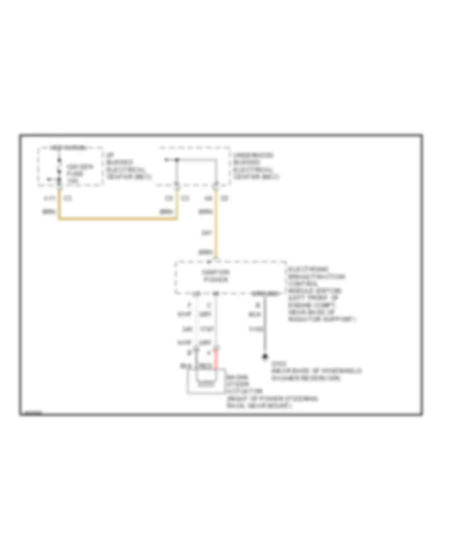
ELECTRONIC POWER STEERING Electronic Power Steering Wiring Diagram for Buick Park Avenue Ultra 1997 List of elements for Electronic Power Steering Wiring Diagram for Buick Park Avenue Ultra 1997: 11 A11 Electronic brake/traction control module (ebtcm) (left front of engine compt, near base of radiator support) G102 (near base of windshield washer reservoir) Ground Hot in run I/p bussed electrical center (bec) Ign sen fuse 10a Ignition power Magna steer actuator (right of power steering rack, near mount) Red Underhood bussed electrical center (bec)
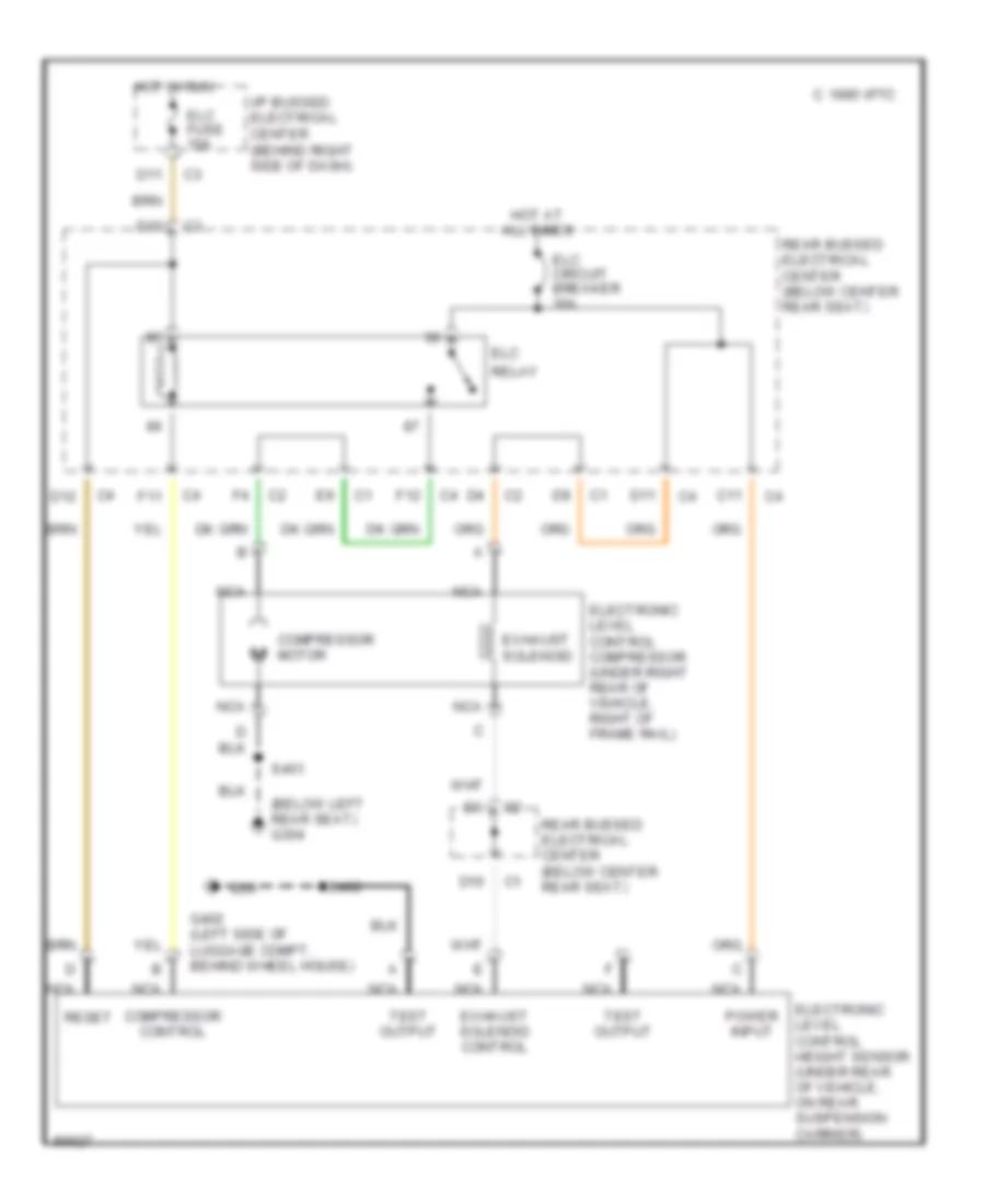
ELECTRONIC SUSPENSION Electronic Suspension Wiring Diagram for Buick Park Avenue Ultra 1997 List of elements for Electronic Suspension Wiring Diagram for Buick Park Avenue Ultra 1997: 29 (below left rear seat) g304 C 1995 vftc C11 Compressor control Compressor motor D10 D11 D12 Elc Elc circuit breaker 30a Elc fuse 10a Electronic level control compressor (under right rear of vehicle, right of frame rail) Electronic level control height sensor (under rear of vehicle, on rear suspension carrier) Exhaust solenoid Exhaust solenoid control F11 F12 G402 (left side of luggage compt, behind wheel house) Hot at all times Hot in run I/p bussed electrical center (behind right side of dash) Nca Power input Rear bussed electrical center (below center rear seat) Relay Reset S400 S401 Test output
ENGINE PERFORMANCE
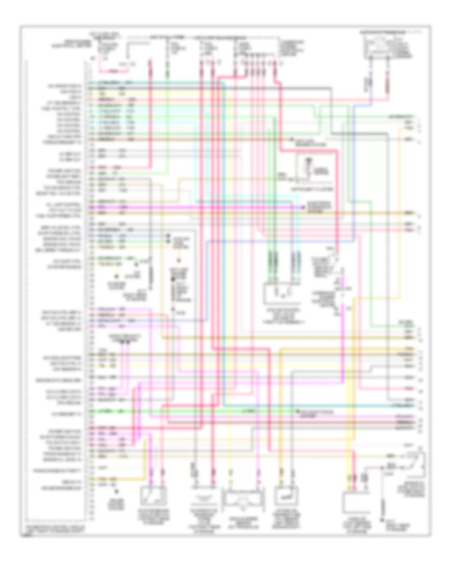
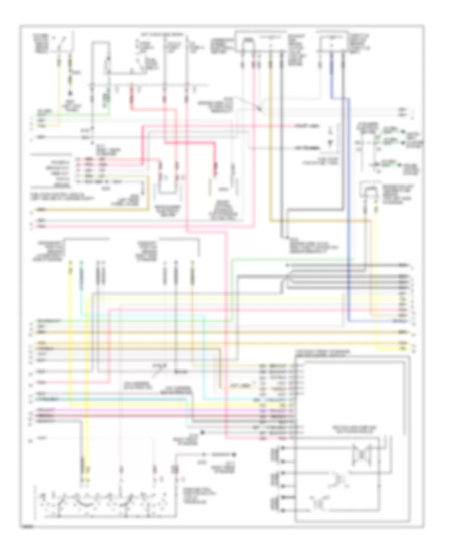
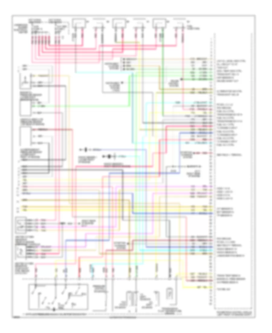
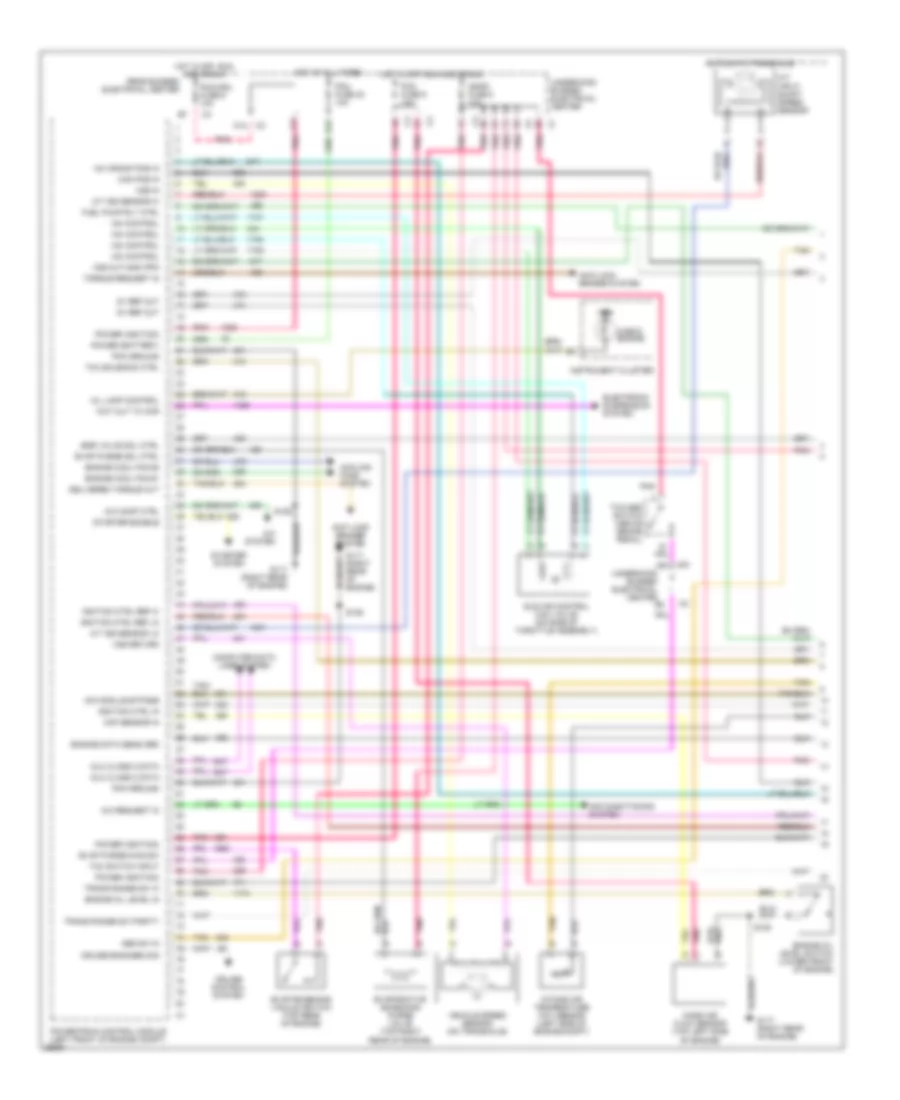
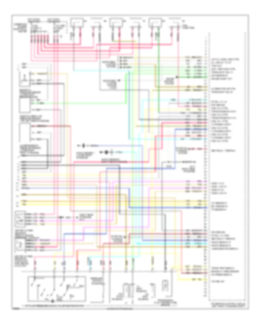
3.8L 3.8L (VIN 1), Engine Performance Wiring Diagrams (1 of 3) for Buick Park Avenue Ultra 1997 List of elements for 3.8L (VIN 1), Engine Performance Wiring Diagrams (1 of 3) for Buick Park Avenue Ultra 1997: 79 18x crank pos in 5v ref out A/c comp ctrl A/c request in A/c system A/t input shaft speed sensor A/t iss sensor hi A/t iss sensor lo A12 Abs sw in Air conditioning system Anti-lock brakes system Automatic transaxle Boost sol valve ctrl Cam pos in Check engine Computer data lines system Cooling fans system Cruise control system Cruise engaged sig Delivered torque out Dlc class 2 data E12 Egr valve sol ctrl Electronic suspension system Engine cool fan #1 Engine cool fan #2 Engine data sens grd Engine oil level in Engine oil level switch (lower front of engine) Evap emissions vacuum switch (top right rear of engine) Evap purge diag sw Evap purge sol ctrl Evaporative emissions purge valve (top right rear of engine) F12 Fuel pump rly ctrl Fuel pump speed ctrl G117 (right rear of engine) Hot at all times Hot in off, run and crank Iac control Icm module bypass Idle air control (iac) valve (on side of throttle assembly) Ign Ignfd fuse 8 10a Ignition ctrl in Ignition ctrl ref hi Ignition ctrl ref lo Instrument cluster Intake air temperature (iat) sensor (left side of engine compt) Maf sensor in Mass air flow sensor (top left side of engine) Mil lamp control Pcm fuse 23 10a Pcm fuse 6 10a Pcm ground Pcm/cru fuse 9 10a Pnk Power (battery) Power (ignition) Powertrain control module (left front of engine compt) Rear bussed electrical center S106 S108 Starter enable Starter system Tan Tcc solenoid ctrl Tcc switch input Tcc/abs switch (above brake pedal) Torque request in Trans range sw 'a' Trans range sw parity Underhood bussed electrical center Vehicle speed sensor (on transaxle) Vss in Vss out-4000 ppm Vss return Wot out to ccr 3.8L (VIN 1), Engine Performance Wiring Diagrams (2 of 3) for Buick Park Avenue Ultra 1997 List of elements for 3.8L (VIN 1), Engine Performance Wiring Diagrams (2 of 3) for Buick Park Avenue Ultra 1997: 53 (icm harness, (icm harness, 20 cm from icm) (left kick (not used) (top right front of engine) ignition control module 26.5 cm from icm) A pnk A/c clu fuse 7 10a B10 Boost control solenoid (top of engine, on fuel rail) C3i fuse 13 10a Camshaft position sensor (right side of engine) Crankshaft position sensor (lower right side of engine) Cruise control system Engine coolant temperature sensor (top left side of engine) Exhaust gas recirc- ulation valve (top left side of engine) F/pmp fuse 21 20a Feed out Fuel pump (top of fuel tank) Fuel pump control module (left center of luggage compt) Fuel pump relay G117 (right rear of engine) G117 (right rear of engine) G119 (right front of engine) G200 G402 (left rear wheel house) Ground Ground out Hot in run and crank I/p bussed electrical center Ignition amplifier and switching module Instru- ment cluster system Nca Panel) Park/neutral position switch (top of transaxle) Plugs spark Pnk Power in Pwm in Rear bussed electrical center Red S103 (engine harn, 6.5 cm from throttle position sensor breakout) S105 (engine harn, 47.5 cm from pcm breakout) S108 S135 S136 S203 S400 Spark plugs Tan Tcc/abs switch (above brake pedal) Throttle position sensor (throttle body) Underhood bussed electrical center 3.8L (VIN 1), Engine Performance Wiring Diagrams (3 of 3) for Buick Park Avenue Ultra 1997 List of elements for 3.8L (VIN 1), Engine Performance Wiring Diagrams (3 of 3) for Buick Park Avenue Ultra 1997: 73 (right rear of engine) g117 1-2 shift solenoid 2-3 shift solenoid A/c press sens in A/c refrigerant pressure sensor (lower right front of engine) A/t fluid pressure manual valve position switch Alternator ind ctrl Automatic transaxle Cool temp indic ctrl Cruise control system Cruise inhibit out Ect sensor in Engine oil pres sensor Engine oil pressure sensor (lower right rear of engine) Fuel inj 1 ctrl Fuel inj 2 ctrl Fuel inj 3 ctrl Fuel inj 4 ctrl Fuel inj 5 ctrl Fuel inj 6 ctrl Fuel injectors G117 (right rear of engine) Gen field 'f' terminal Gen field 'l' terminal Heated oxygen sensor #1 (rear of engine, in exhaust manifold) Heated oxygen sensor #2 (in exhaust pipe, behind catalyst) Ho2s 1 hi in Ho2s 1 low in Ho2s 2 hi in Ho2s 2 low in Hot in run and crank Iat sensor in Injr fuse 12 10a Instrument cluster system Instrument cluster system (tach) Knock sens #1 in Knock sens #2 in Knock sensor 1 (lower front of engine) Knock sensor 2 (right rear of engine) Linear egr pos sens in Low oil level indic ctrl Manifold absolute pressure sensor (top rear of engine) Map sensor in Nca Oil life out to i/p Oxy sen fuse 4 10a Pc sol vlv high Pc sol vlv lo Pcm ground Pnk Powertrain control module (left front of engine compt) Pressure control solenoid Red Red/ S106 S108 Starting/ charging system Tach out Tan Tcc (pwm) solenoid Tcc rel Tcc rel sw Tp sensor in Trans range sw 'b' in Trans range sw 'c' in Trans shift sol 'a' Trans shift sol 'b' Trans temp sens in Transmission fluid temperature sensor Tx range a input Tx range b input Tx range c input Underhood bussed electrical center 3.8L (VIN K), Engine Performance Wiring Diagrams (1 of 3) for Buick Park Avenue Ultra 1997 List of elements for 3.8L (VIN K), Engine Performance Wiring Diagrams (1 of 3) for Buick Park Avenue Ultra 1997: 77 18x crank pos in 5v ref out A/c comp ctrl A/c request in A/c system A/t input shaft speed sensor A/t iss sensor hi A/t iss sensor lo A12 Abs sw in Air conditioning system Anti-lock brakes system Automatic transaxle Cam pos in Check engine Computer data lines system Cooling fans system Cruise control system Cruise engaged sig Delivered torque out Dlc class 2 data E12 Egr valve sol ctrl Electronic suspension system Engine cool fan #1 Engine cool fan #2 Engine data sens grd Engine oil level in Engine oil level switch (lower front of engine) Evap emissions vacuum switch (top rear of engine) Evap purge diag sw Evap purge sol ctrl Evaporative emissions purge valve (top right rear of engine) F12 Fuel pump rly ctrl G117 (right rear of engine) Hot at all times Hot in off, run and crank Iac control Icm module bypass Idle air control (iac) valve (on side of throttle assembly) Ign Ignfd fuse 8 10a Ignition ctrl in Ignition ctrl ref hi Ignition ctrl ref lo Instrument cluster Intake air temperature (iat) sensor (left side of engine compt) Maf sensor in Mass air flow sensor (top left side of engine) Mil lamp control Pcm fuse 23 10a Pcm fuse 6 10a Pcm ground Pcm/cru fuse 9 10a Pnk Power (battery) Power (ignition) Powertrain control module (left front of engine compt) Rear bussed electrical center S106 S108 Starter enable Starter system Tan Tcc solenoid ctrl Tcc switch input Tcc/abs switch (above brake pedal) Torque request in Trans range sw 'a' Trans range sw parity Underhood bussed electrical center Vehicle speed sensor (on transaxle) Vss in Vss out-4000 ppm Vss return Wot out to ccr 3.8L (VIN K), Engine Performance Wiring Diagrams (2 of 3) for Buick Park Avenue Ultra 1997 List of elements for 3.8L (VIN K), Engine Performance Wiring Diagrams (2 of 3) for Buick Park Avenue Ultra 1997: 43 (icm harness, (icm harness, 20 cm from icm) (left kick (not used) (top right front of engine) ignition control module 26.5 cm from icm) B10 C3i fuse 13 10a Camshaft position sensor (right side of engine) Crankshaft position sensor (lower right side of engine) Cruise control system Engine coolant temperature sensor (top left side of engine) Exhaust gas recirc- ulation valve (top left side of engine) F/pmp fuse 21 20a Fuel pump (top of fuel tank) Fuel pump relay G117 (right rear of engine) G117 (right rear of engine) G119 (right front of engine) G200 G402 (left rear wheel well) Hot in run and crank I/p bussed electrical center Ignition amplifier and switching module Instru- ment cluster system Nca Panel) Park/neutral position switch (top of transaxle) Plugs spark Pnk Rear bussed electrical center S103 (engine harn, 6.5 cm from throttle position sensor breakout) S105 (engine harn, 47.5 cm from pcm breakout) S108 S135 S136 S203 S400 Spark plugs Tan Tcc/abs switch (above brake pedal) Throttle position sensor (throttle body) Underhood bussed electrical center 3.8L (VIN K), Engine Performance Wiring Diagrams (3 of 3) for Buick Park Avenue Ultra 1997 List of elements for 3.8L (VIN K), Engine Performance Wiring Diagrams (3 of 3) for Buick Park Avenue Ultra 1997: 73 (right rear of engine) g117 1-2 shift solenoid 2-3 shift solenoid A/c press sens in A/c refrigerant pressure sensor (lower right front of engine) A/t fluid pressure manual valve position switch Alternator ind ctrl Automatic transaxle Cool temp indic ctrl Cruise control system Cruise inhibit out Ect sensor in Engine oil pres sensor Engine oil pressure sensor (lower right rear of engine) Fuel inj 1 ctrl Fuel inj 2 ctrl Fuel inj 3 ctrl Fuel inj 4 ctrl Fuel inj 5 ctrl Fuel inj 6 ctrl Fuel injectors G117 (right rear of engine) Gen field 'f' terminal Gen field 'l' terminal Heated oxygen sensor #1 (rear of engine, in exhaust manifold) Heated oxygen sensor #2 (in exhaust pipe, behind catalyst) Ho2s 1 hi in Ho2s 1 low in Ho2s 2 hi in Ho2s 2 low in Hot in run and crank Iat sensor in Injr fuse 12 10a Instrument cluster system Instrument cluster system (tach) Knock sens #1 in Knock sens #2 in Knock sensor 1 (lower front of engine) Knock sensor 2 (right rear of engine) Linear egr pos sens in Low oil level indic ctrl Manifold absolute pressure sensor (top left rear of engine) Map sensor in Nca Oil life out to i/p Oxy sen fuse 4 10a Pc sol vlv high Pc sol vlv lo Pcm ground Pnk Powertrain control module (left front of engine compt) Pressure control solenoid Red Red/ S106 S108 Starting/ charging system Tach out Tan Tcc (pwm) solenoid Tcc rel Tcc rel sw Tp sensor in Trans range sw 'b' in Trans range sw 'c' in Trans shift sol 'a' Trans shift sol 'b' Trans temp sens in Transmission fluid temperature sensor Tx range a input Tx range b input Tx range c input Underhood bussed electrical center
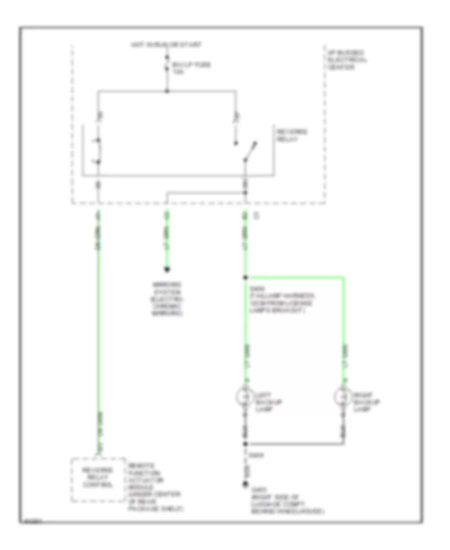
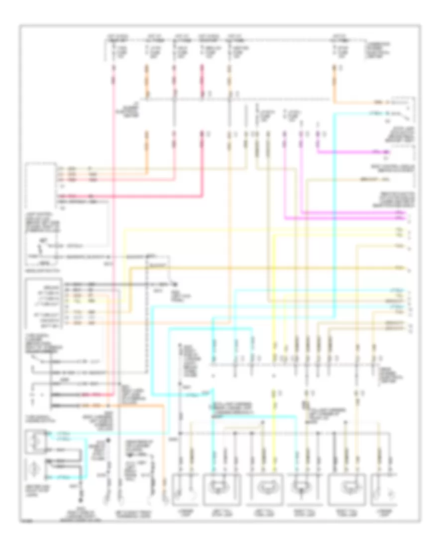
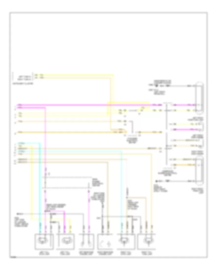
EXTERIOR LIGHTS Back-up Lamps Wiring Diagram for Buick Park Avenue Ultra 1997 List of elements for Back-up Lamps Wiring Diagram for Buick Park Avenue Ultra 1997: 12 B/u lp fuse 10a G403 (right side of luggage compt, behind wheelhouse) Hot in run or start I/p bussed electrical center Left backup lamp Mirrors system (electro- chromic mirrors) Remote function actuator module (under center of rear package shelf) Reverse relay Reverse relay control Right backup lamp S408 (taillamp harness, 12cm from license lamps brakout) S409 Exterior Lamps Wiring Diagram (1 of 2) for Buick Park Avenue Ultra 1997 List of elements for Exterior Lamps Wiring Diagram (1 of 2) for Buick Park Avenue Ultra 1997: 69 (1997) (1998) (near rear of air cleaner housing) g106 (taillamp harness, near license lamp harness breakout) s407 A10 A11 A14 B10 B11 B12 Batt (b+) Body control module (behind glove box) C12 Center high mount stop lamps D12 E11 E12 F10 G103 (base of right strut tower) G113 (left front frame rail) G200 (left kick panel) G403 (right side of luggage compt, behind wheel- house) G403 (right side of luggage compt, behind wheelhouse) Ground Haz sig in Hdlp fuse 30a Head Headlamp switch Hot at all times Hot in run or start Hzdt/sg fuse 15a I/p bussed electrical center Lamp control module (lcm) (behind left side of dash, right of steering column) Left & right front cornering lamps Left tail/ stop lamp Left tail/ turn lamp License lamp Lp pk fuse 25a Lp pk l fuse 10a Lp pk r fuse 15a Lt turn in Lt turn out Nca Off Park Pnk Rear bussed electrical center Red Remote function actuator module (under center of rear package shelf) Right tail/ stop lamp Right tail/ turn lamp Rt turn in Rt turn out S200 (body harness, left side of steering column) S201 (body harn, left side of steering column) S203 S210 S213 S299 S401 S409 Sbm/lcm fuse 10a Stop fuse 10a Stop lamp/ btsi switch (brake pedal bracket assy) T/sig fuse 10a Tan Turn signal flasher (behind dash, right of steering column carrier) Turn signal/ hazard switch Underhood bussed electrical center Exterior Lamps Wiring Diagram (2 of 2) for Buick Park Avenue Ultra 1997 List of elements for Exterior Lamps Wiring Diagram (2 of 2) for Buick Park Avenue Ultra 1997: 32 (near rear of air cleaner housing) g106 (1998) (rear lamp harness, left rear corner of trunk) s402 (right side of luggage compt, behind wheelhouse) g403 B11 E10 G103 (base of right front strut tower) G113 (1997) (left front frame rail) G402 (left side of luggage compt, behind wheelhouse) I/p bussed electrical center Instrument cluster Left front park/turn lamp Left front side marker Left rear side marker lamp Left tail/ stop lamp Left tail/ turn lamp Left turn in Rear bussed electrical center Right front park/turn lamp Right front side marker Right rear side marker lamp Right tail/ stop lamp Right tail/ turn lamp Right turn in S101 S102 S400 S401 S403 (rear lamp harness, right rear of trunk) S404 S405 Tan Underhood bussed electrical center
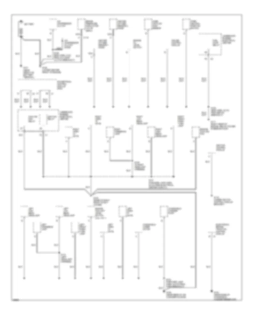
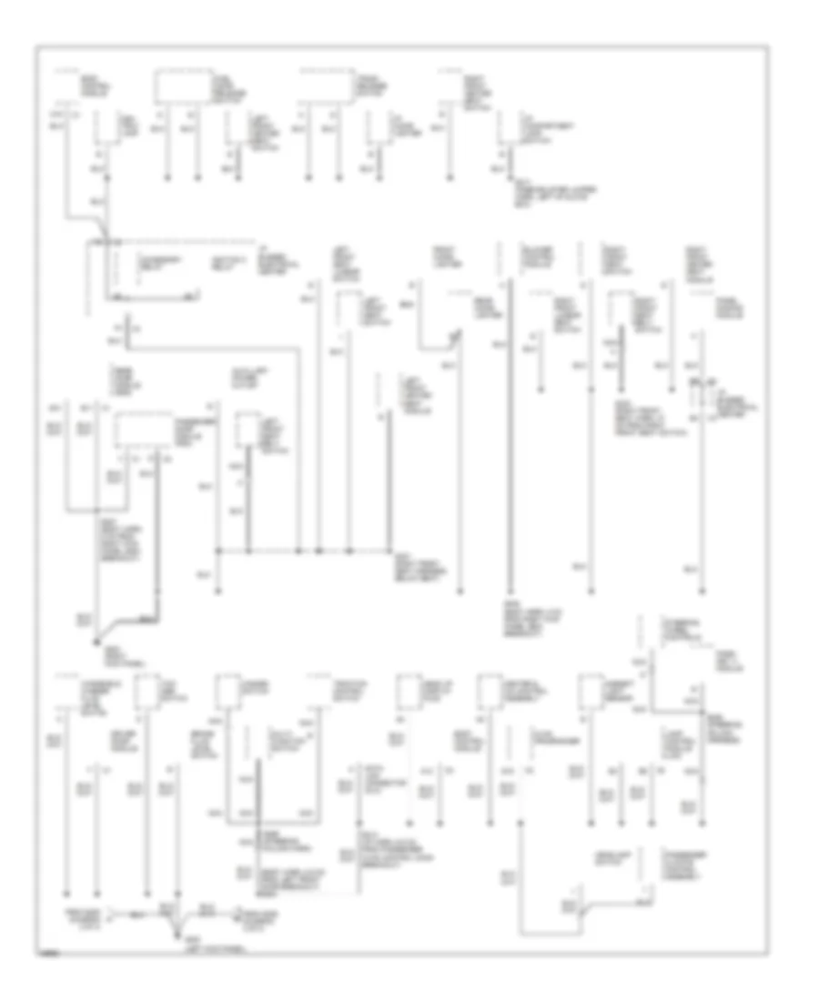
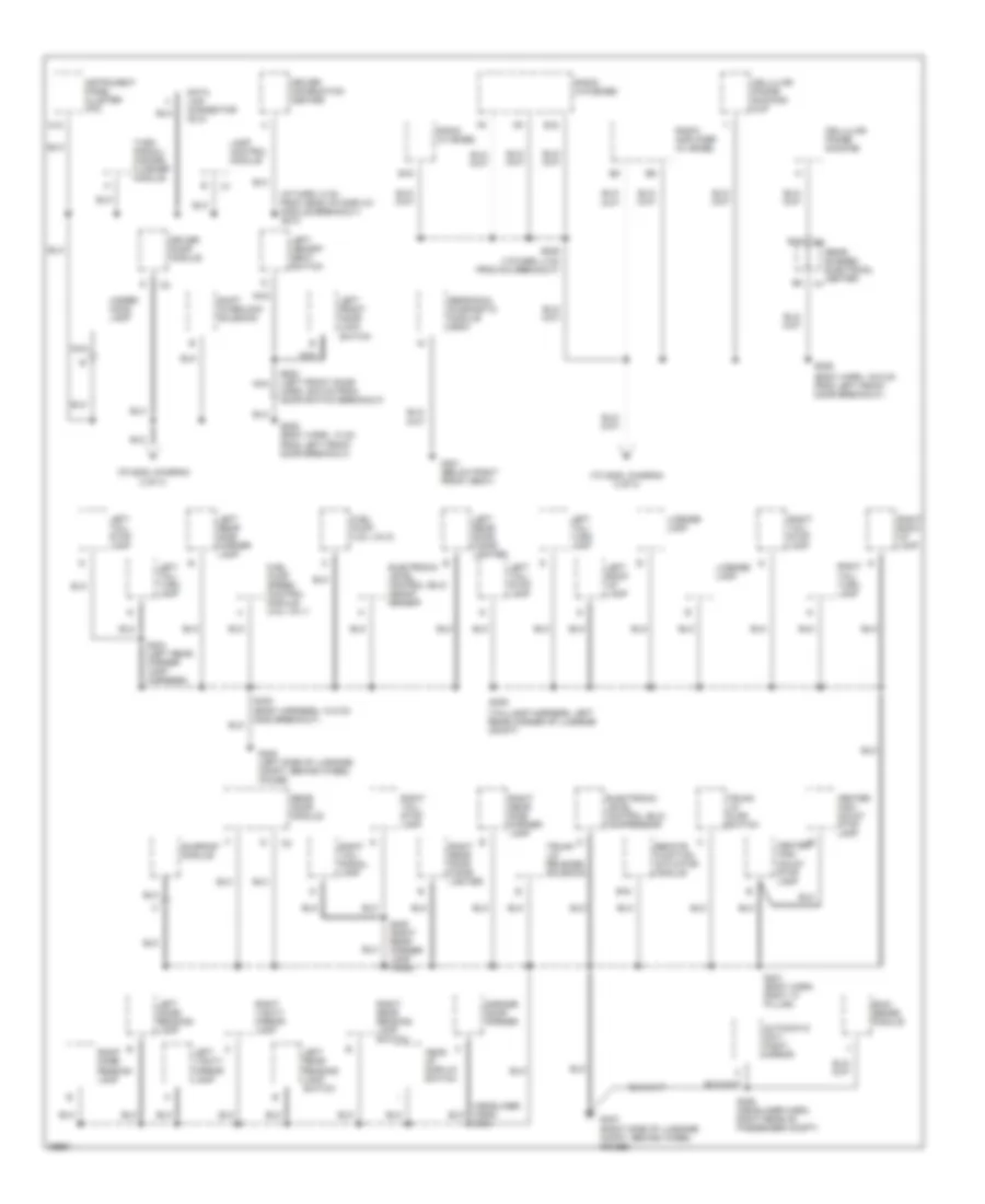
GROUND DISTRIBUTION Ground Distribution Wiring Diagram (1 of 3) for Buick Park Avenue Ultra 1997 List of elements for Ground Distribution Wiring Diagram (1 of 3) for Buick Park Avenue Ultra 1997: 48 A/c compressor clutch A/c compressor clutch diode Battery Brake pressure modulator valve (bpmv) C119 Cooling fan relay Cruise control module E10 Electronic brake/ traction control module Engine coolant level switch (3.8l vin 1) Engine cooling fan Engine oil level switch Fuel pump relay G102 (near base of windshield washer reservoir) G103 (base of right front strut tower) G106 (near rear of air cleaner housing) G117 (right rear of engine, below power steering pump) G119 (under igniton control module bracket) G125 (lower center front of engine) Heated oxygen sensor 1 (h02s) Heated oxygen sensor 2 (h02s) Ignition control module Ignition relay Left cornering lamp Left front park/ turn lamp Left high beam headlamp Left horn "a" note Left horn "f" note Left low beam headlamp Mass air flow (maf) sensor Nca Park/ neutral position switch Powertrain control module (pcm) Right cornering lamp Right front park/ turn lamp Right high beam headlamp Right horn "c" note Right horn "d" note Right low beam headlamp S101 (forward lamp harn, 54 cm from electrical center conn c1) S102 (forward lamp harn, 6.5 cm from horn breakout) S106 (eng harn, 6 cm from a/c comp clutch breakout) S108 (eng harn, 20 cm from ebtcm breakout) S109 (in right headlamp harness) S110 (left headlamp harness) Underhood bussed electrical center Windshield washer pump Windshield wiper motor Ground Distribution Wiring Diagram (2 of 3) for Buick Park Avenue Ultra 1997 List of elements for Ground Distribution Wiring Diagram (2 of 3) for Buick Park Avenue Ultra 1997: 63 (body harn, 6.5 cm from left front door breakout) s203 (left kick panel) A11 a11 A12 Accessory relay Ambient light sensor Ash tray lamp Auxillary power outlet B11 Blower control module Body control module Brake fluid level switch C16 D16 Data link connector (dlc) Driver door module From s205 (diagram 3 of 3) From s206 (diagram 3 of 3) Front cigar lighter Fuel door release switch G200 G203 (right kick panel) Hazard switch Head up display (hud) Headlamp switch Heater & a/c control assembly Hvac control conn breakout) Hvac programmer I/p bussed electrical center I/p cigar lighter I/p compartment lamp switch Ignition 3 relay Lamp control module (lcm) Left front heated seat module Left front heated seat switch Left front seat belt switch Left front seat lumbar switch Left front seat switch Multi- function switch Nca Panel dimming module Pass- key iii module Passenger climate control assembly Passenger door module (pdm) Rear cigar lighter Rear door module (rdm) Right front heated seat module Right front heated seat switch Right front lumbar seat switch Right front seat belt switch Right front seat switch S207 (body harn, 5 cm from right kick panel g203 breakout) S208 (body harn, 8 cm from right kick panel g203 breakout) S217 (knee bolster jumper harn, left of glove box) S298 (steering column harness) S299 (steering column harn) S333 (right front seat harn, 37 cm from right front seat switch) S337 (right front seat harness, below seat) Steering wheel controls Tcc/ abs switch Traction control switch Trunk release switch Windshield washer fluid level switch Ground Distribution Wiring Diagram (3 of 3) for Buick Park Avenue Ultra 1997 List of elements for Ground Distribution Wiring Diagram (3 of 3) for Buick Park Avenue Ultra 1997: 75 (body harn, 19.5 cm from left front door breakout) (body harness, 10.5 cm g402 breakout) (headliner harn) s303 (i/p harn, 5 cm from head up display module breakout) s210 (taillamp harness, left rear corner of luggage compt) (to g200, diagram (to g200, diagram 2 of 3) 2 of 3) A12 Automatic day/ night mirror B10 B16 Cellular phone docking Cellular phone docking cup Center high mount stop lamp Data link connector (dlc) Driver door module Driver information center E16 Electronic level control (elc) compressor Electronic level control (elc) height sensor Fuel pump (3.8l vin k) Fuel pump speed control module (3.8l vin 1) G301 (below right front seat) G402 (left side of luggage compt, behind wheel house) G403 (right side of luggage compt, behind wheel house) Garage door opener Head up display switch Instrument panel cluster (ipc) Lamp control module Left back up lamp Left dome/ reading lamp Left front door lock switch Left memory seat switch Left rear door cigar lighter Left rear reading lamp switch Left rear side marker lamp Left tail/ stop lamp Left tail/ turn lamp Left vanity mirror lamp License lamp Nca Radio (w/ bose) Radio (w/o bose) Radio amplifier (w/ bose) Rain sense module Rear bussed electrical center Rear door module Remote function actuator module Right back up lamp Right dome/ reading lamp Right rear door cigar lighter Right rear reading lamp switch Right rear side marker lamp Right tail/ signal lamp Right tail/ stop lamp Right tail/ turn lamp Right vanity mirror lamp S205 (body harn, 13 cm from left front door breakout) S206 S209 (i/p harn, 4 cm from dic breakout) S306 (headliner harn, right rear of passenger compt) S400 S401 (body harn, right "c" pillar) S404 (left rear corner lamp harness) S405 (right rear corner lamp harn) S409 S503 (left front door harn, 29.5 cm from door switch breakout) Sensing & diagnostic module (sdm) Shift interlock solenoid Sunroof module Trunk lid ajar switch Trunk lid release solenoid Turn signal/ hazard flasher module Under- hood lamp
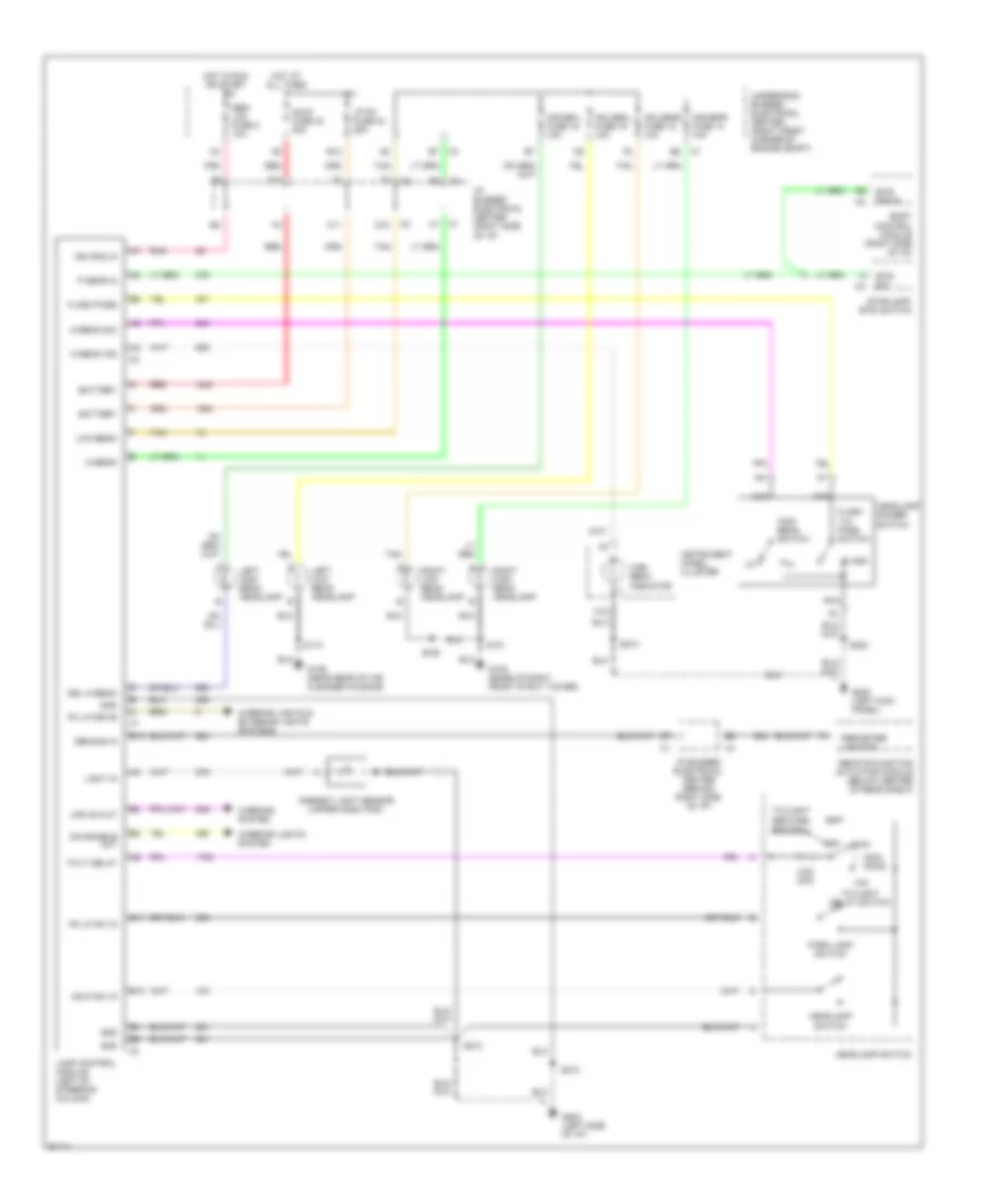
HEADLIGHTS Headlight Wiring Diagram for Buick Park Avenue Ultra 1997 List of elements for Headlight Wiring Diagram for Buick Park Avenue Ultra 1997: 82 200k ohms 3.6k ohm A11 A12 Ambient light sensor (upper dash pad) B10 B11 B12 Battery Body control module (right side of i/p) Btsi drive Btsi sw D10 Demand in Dim enable out Drl hi-beam E12 F10 Flash Flash -to- pass switch Flash pass G105 (base of right front strut tower) G106 (near rear of air cleaner housing) G202 (left kick panel) G202 (left side of i/p) Gnd Hdhibml fuse 16 10a Hdhibmr fuse 14 10a Hdlobml fuse 19 10a Hdlobmr fuse 18 10a Hdlp fuse 40 30a Hdlp sw in Headlamp dimmer switch Headlamp switch Hi-beam Hi-beam ind Hi-beam sw High beam indicator High beam switch Hot at all times Hot in run or start I/p bussed electrical center (behind right side of i/p) I/p bussed electrical center (right side of i/p) Ign (r/s) in Instrument panel cluster Interior lights & exterior lights systems Interior lights system Lamp control module (left of steering column) Left high beam headlamp Left low beam headlamp Light in Low-beam Lp pk fuse 24 25a Lps on out Max Min Nca Off P gear in Park lamp switch Perimeter lighting Pk lp drive Pk lp sw in Pnk Red Remote function actuator module (below center of rear shelf) Right high beam headlamp Right low beam headlamp S101 S109 S110 S203 S210 S213 Sbm/ lcm fuse 2 10a Stoplamp/ btsi switch Tan Twilight delay switch Twilight sentinel switch Twlt delay Underhood bussed electrical center (right front corner of engine compt) Warning system
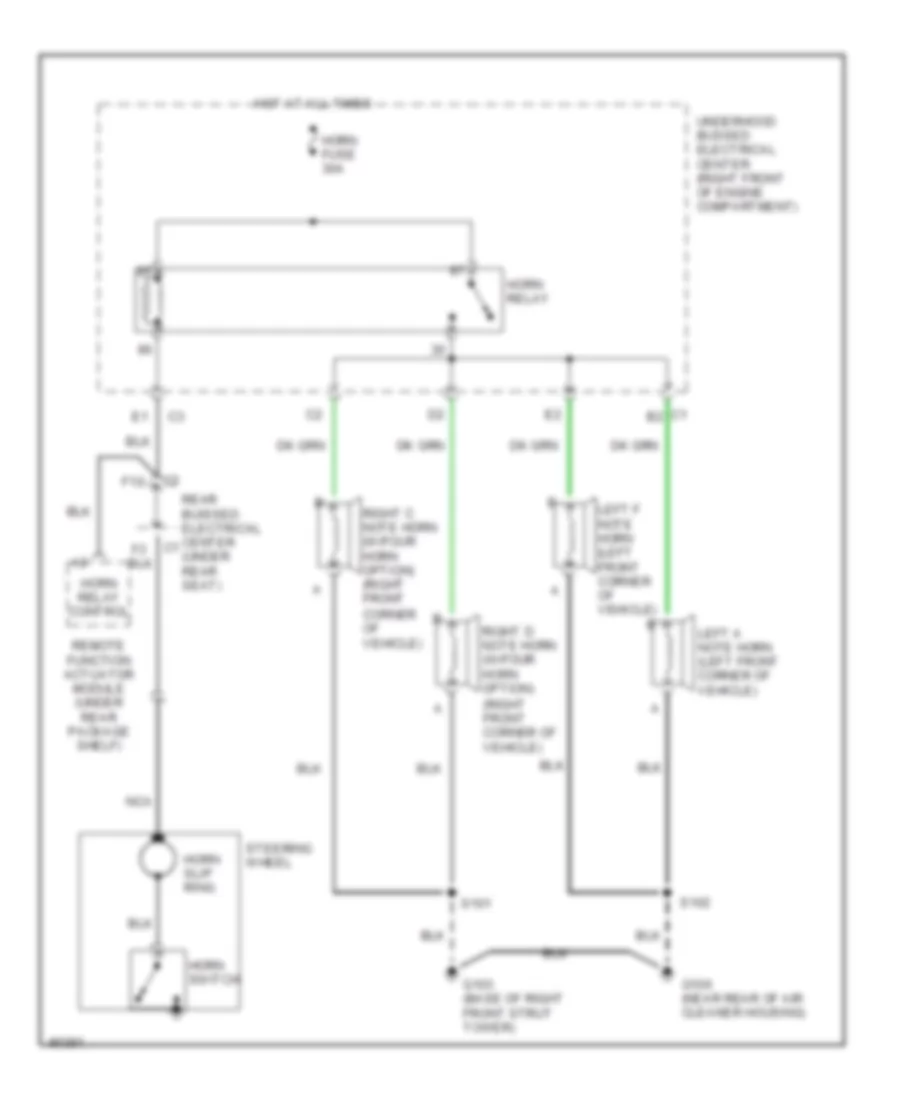
HORN Horn Wiring Diagram for Buick Park Avenue Ultra 1997 List of elements for Horn Wiring Diagram for Buick Park Avenue Ultra 1997: 22 (right front corner of vehicle) C1 b2 F10 G103 (base of right front strut tower) G106 (near rear of air cleaner housing) Horn fuse 30a Horn relay Horn relay control Horn slip ring Horn switch Hot at all times Left a note horn (left front corner of vehicle) Left f note horn (left front corner of vehicle) Nca Rear buissed electrical center (under rear seat) Remote function actuator module (under rear package shelf) Right c note horn (w/four horn option) (right front corner of vehicle) Right d note horn (w/four horn option) S101 S102 Steering wheel Underhood bussed electrical center (right front of engine compartment)
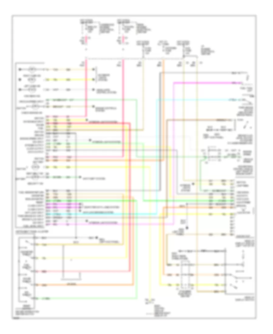
INSTRUMENT CLUSTER Instrument Cluster Wiring Diagram for Buick Park Avenue Ultra 1997 List of elements for Instrument Cluster Wiring Diagram for Buick Park Avenue Ultra 1997: 96 A10 A11 A12 A13 A14 A15 A16 A17 Anti-lock brakes system Anti-lock input Anti-theft system B10 B11 B12 B13 B14 B15 B16 B17 Battery Body control module (behind right side of i/p) Brake fluid input Brake fluid level switch (in master cylinder reservoir) C11 Check engine ind Class 2 data Clock output Computer data lines system Cstr/sbm fuse 10a Data output Dim enable input Dim input Driver information center switch E/m switch Engine controls system Engine speed Engine speed input English/metric Exterior lights system Fuel Fuel level input Fuel sensor return Fuel switch Fuel tank unit G200 (left kick panel) G403 (right rear wheelhouse) Gauge Gauge switch Ground Head up display module (left top of i/p) Head up display switch Headlamps control system High beam ind Hot at all times Hot in run and start Hud clock Hud data Hud fuse 10a Hud motor Hud strobe Hud sw out Hvac fuse 10a I/p bussed electrical center Ignition Instrument panel cluster Interior lights system Lamp feed Left turn ind Odometer Odometer switch Park brake sw input Park brake switch (above park brake pedal) Pcm/cru fuse 10a Pnk Pnk e5 Pnk f6 Powertrain control module (left front of engine compt) Rear bussed electrical center Red Reset Reset switch Right turn ind S203 S210 S213 S303 Seat belt ind Security ind Smb/lcm fuse 10a Strobe output Tan Underhood bussed electrical center Uplevel Vehicle speed Vehicle speed input Vss signal
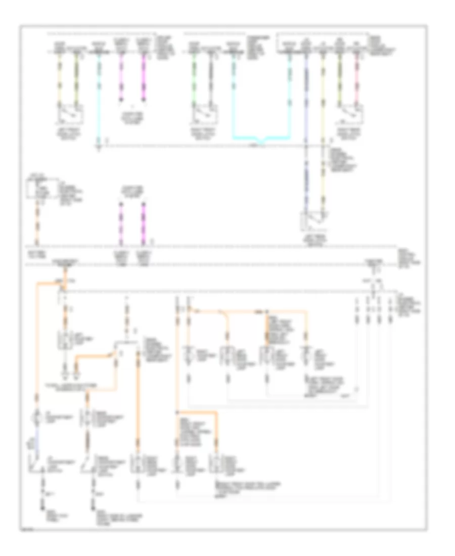
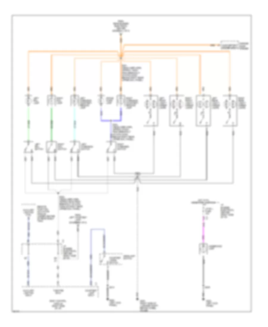
INTERIOR LIGHTS Courtesy Lamps Wiring Diagram (1 of 2) for Buick Park Avenue Ultra 1997 List of elements for Courtesy Lamps Wiring Diagram (1 of 2) for Buick Park Avenue Ultra 1997: 55 (left front door harn, approx 4cm from left door sw breakout) s501 A10 c4 A3 c1 A9 c1 Actuator gnd a c3 B10 Battery voltage Body control module (right side of i/p) C10 Class 2 serial data line Class 2 serial data line c1 Computer data lines system D1 c2 D4 c1 D9 c4 Door open input c Driver door module (center front of door) E6 c2 G203 (right kick panel) G403 (right side of luggage compt, behind wheel house) Hot at all times I/p bussed electrical center (right side of i/p) I/p compartment lamp I/p compartment lamp switch Inadvertent power d1 Left courtesy lamp Left front door courtesy lamp Left front door latch switch Left rear door courtesy lamp Left rear door latch switch Lr actuator gnd a9 Lr door open input f9 Passenger door module (center front of door) Rear bussed electrical center (under right rear seat) Rear compartment courtesy lamp Rear compartment courtesy lamp switch Rear door module (under right rear seat) Red Right courtesy lamp Right front door courtesy lamp Right front door latch switch Right rear door courtesy lamp Right rear door latch switch Rr actuator gnd a3 c1 Rr door open input a5 S217 S401 S600 (right front door trim jumper, approx 61cm from 8-pin conn in rf door) Sbm fuse 15a Simple bus interface Simple bus interface a12 Simple bus interface c1 Tan Theatre dim-1 c14 c1 To rail lamps & switches (diagram 2 of 2) Courtesy Lamps Wiring Diagram (2 of 2) for Buick Park Avenue Ultra 1997 List of elements for Courtesy Lamps Wiring Diagram (2 of 2) for Buick Park Avenue Ultra 1997: 41 Auxiliary lighting ctrl b1 Auxiliary lighting input Body control module (right side of i/p) C15 C5 c3 Courtesy lamp input Courtesy lamps switch D10 D13 From left courtesy lamp (diagram 1 of 2) From rear bussed electrical center (diagram 1 of 2) G200 (left kick panel) G403 (right side of luggage compt, behind wheel house) Garage door opener Headlamp switch Hot with head/park lamps on I/p bussed electrical center (right side of i/p) Inadvertent power input Left front vanity mirror lamps Left overhead courtesy/ reading lamp Left overhead switch Left rail lamp Left rail switch Left rear vanity mirror lamps Lp pk l fuse 10a Office work lamp Remote function actuator module (under center of rear shelf trim) Right front vanity mirror lamps Right overhead courtesy/ reading lamp Right overhead switch Right rail lamp Right rail switch Right rear vanity mirror lamps S205 S213 S301 (headliner harn, approx 148cm from breakout of 8-pin conn behind right rear upper sail panel) S302 (headliner harn, approx 60cm from breakout of 8-pin conn on right rear upper sail panel) S303 S304 (headliner harn, approx 272cm from breakout of 8-pin conn behind right rear upper sail panel) Theatre dim-2 Underhood lamp Instrument Illumination Wiring Diagram for Buick Park Avenue Ultra 1997 List of elements for Instrument Illumination Wiring Diagram for Buick Park Avenue Ultra 1997: 68 (behind left side of i/p) (i/p harn, approx 6 cm from radio breakout) s211 (knee bolster jumper harn, behind center of i/p) s216 (right kick panel) A11 A14 Ashtray lamp B16 B3 nca D14 Dim enable in Dim enable input Dim enable output Dim input Dimmimg control Dimming in Dimming input Dimming out Driver door module (ddm) (behind left front door trim) Driver door switch (dds) Driver information center (dic) E16 G200 (left kick panel) G203 G203 (right kick panel) G403 (right side of luggage compt, behind wheel house) Gnd Ground Head-up display (hud) module (left side of i/p) Head-up display (hud) switch Headlamp switch Heater and a/c control assembly (6 bulbs) Hot in start or run Hud fuse 10a Hvac programmer I/p bussed electrical center (bec) (behind right side c3 of i/p) I/p bussed electrical center (bec) (behind right side of i/p) Instrument cluster Lamp control module (lcm) Left front door Left front heated seat switch Lock switch Nca Panel dimming module Park lamp drive Passenger climate control assembly Passenger door module (pdm) (behind right front door trim) Pnk Prk lp input Radio Right front door Right front heated seat switch Right front window switch S205 S208 S209 S210 S212 (i/p harn, approx 14 cm from pass hvac control breakout) S213 S217 S303 S502 (left front door harn, in left front door) S503 S602 (right front door harn, in right front door) Steering wheel controls (4 bulbs) Vf dim in Vf dim input Vf dim out
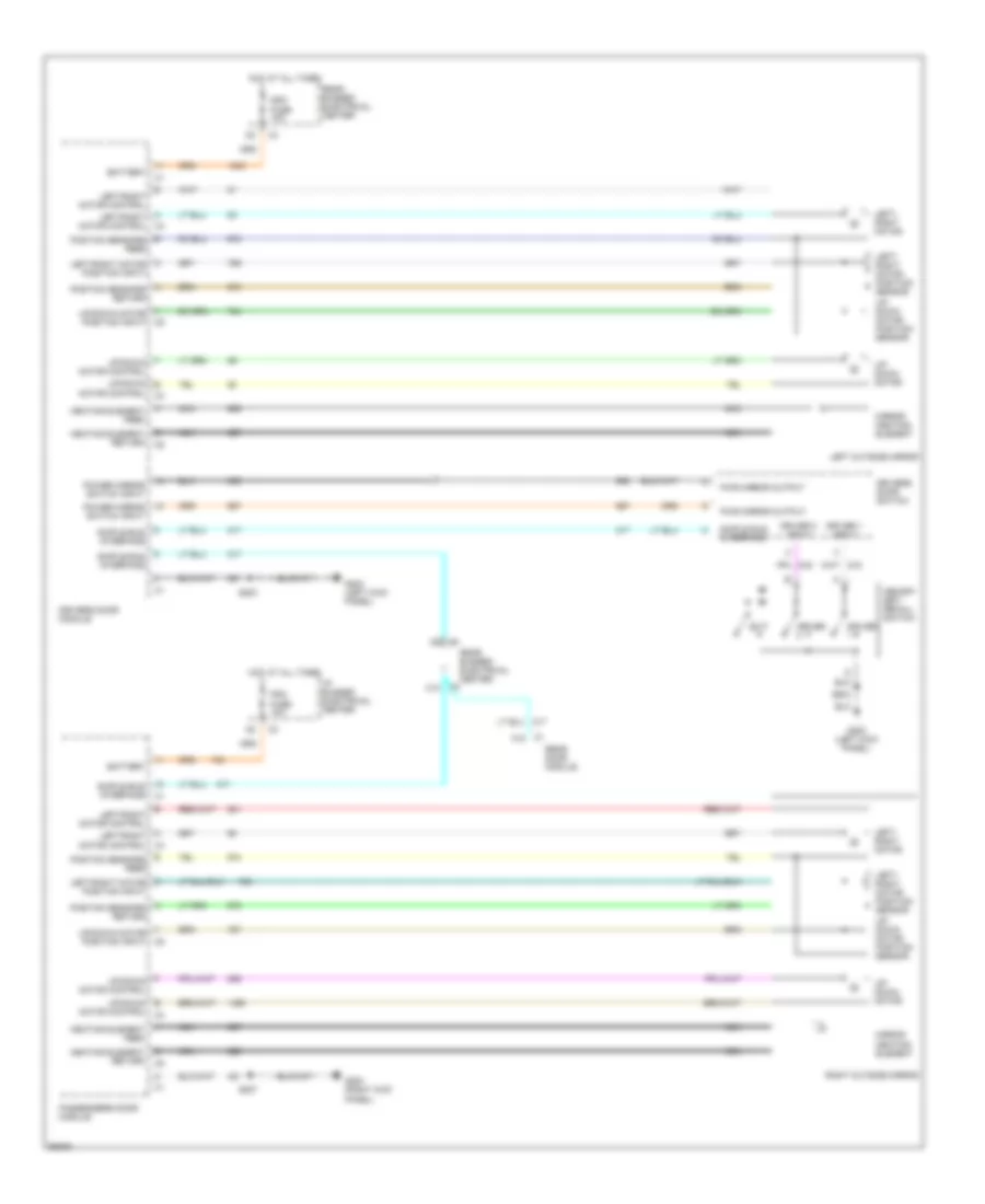
MEMORY SYSTEMS Memory Mirrors Wiring Diagram for Buick Park Avenue Ultra 1997 List of elements for Memory Mirrors Wiring Diagram for Buick Park Avenue Ultra 1997: 45 A left/right motor control A postion sensors return Battery C1 a12 C1 c3 C2 c10 Ddm fuse 10a Driver Driver 1 input Driver 2 input Drivers door module Drivers door switch E postion sensors feed Exit F up/down motor control F up/down motor position input G left/right motor position input G200 (left kick panel) G203 (right kick panel) Heating element feed Heating element return Hot at all times I/p bussed electrical center Left outside mirror Left/ right motor Left/ right motor position sensor Left/right motor control Memory set/ recall switch Mirror heating element Motor control c4 Nca Passengers door module Pdm fuse 10a Power mirror switch input Pwr mirror output Rear bussed electrical center Rear door module Right outside mirror S203 S207 S503 Simple bus interface Up/ down motor Up/ down motor position sensor Up/down b Memory Seat Wiring Diagram for Buick Park Avenue Ultra 1997 List of elements for Memory Seat Wiring Diagram for Buick Park Avenue Ultra 1997: 89 (mem seat harn, 23 cm from memory seat module) (mem seat harn, left front seat) A10 A11 Battery C10 C11 C12 C13 C14 C15 C16 Class 2 data D10 D11 D12 D13 D14 D15 D16 Driver Driver 1 input Driver 2 input Drivers door module Drivers door switch Exit F10 Frnt hgt mtr sens in Front Front height sw input Fwd Fwd-bk mtr sens in Fwd/bk sw unput G200 (left kick panel) G203 (right kick panel) Ground Head restraint Head restraint sw in Hot at all times Hot in run or start I/p bussed electrical center Ign sen fuse 10a Ignition Left forward back motor Left forward back motor position sensor Left front height motor Left front height motor position sensor Left front seat switch Left head restraint up-dn motor Left rear height motor Left rear height motor position sensor Left recliner motor Left recliner motor position sensor Lumbar down in Lumbar in input Lumbar in/out motor Lumbar in/out motor position sensor Lumbar in/out sens in Lumbar out in Lumbar switch Lumbar up in Lumbar up/dn motor Lumbar up/dn motor position sensor Lumbar up/dn sens in Mem/ rfa fuse 10a Memory seat module (under left front seat) Memory set/ recall switch Out Pnk a Position sensors feed Pwr seat circuit breaker 25a Rear Rear bussed electrical center Rear height sw input Rear hgt mtr sens in Recline Recline mtr sens in Recliner sw input Red S334 S335 (mem seat harn, 33 cm from in- line conn to seat belt sw) S336 S337 S338 S503 Simple bus interface Solid state Tan Tan a
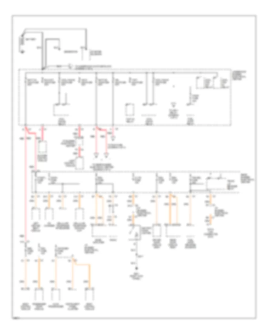
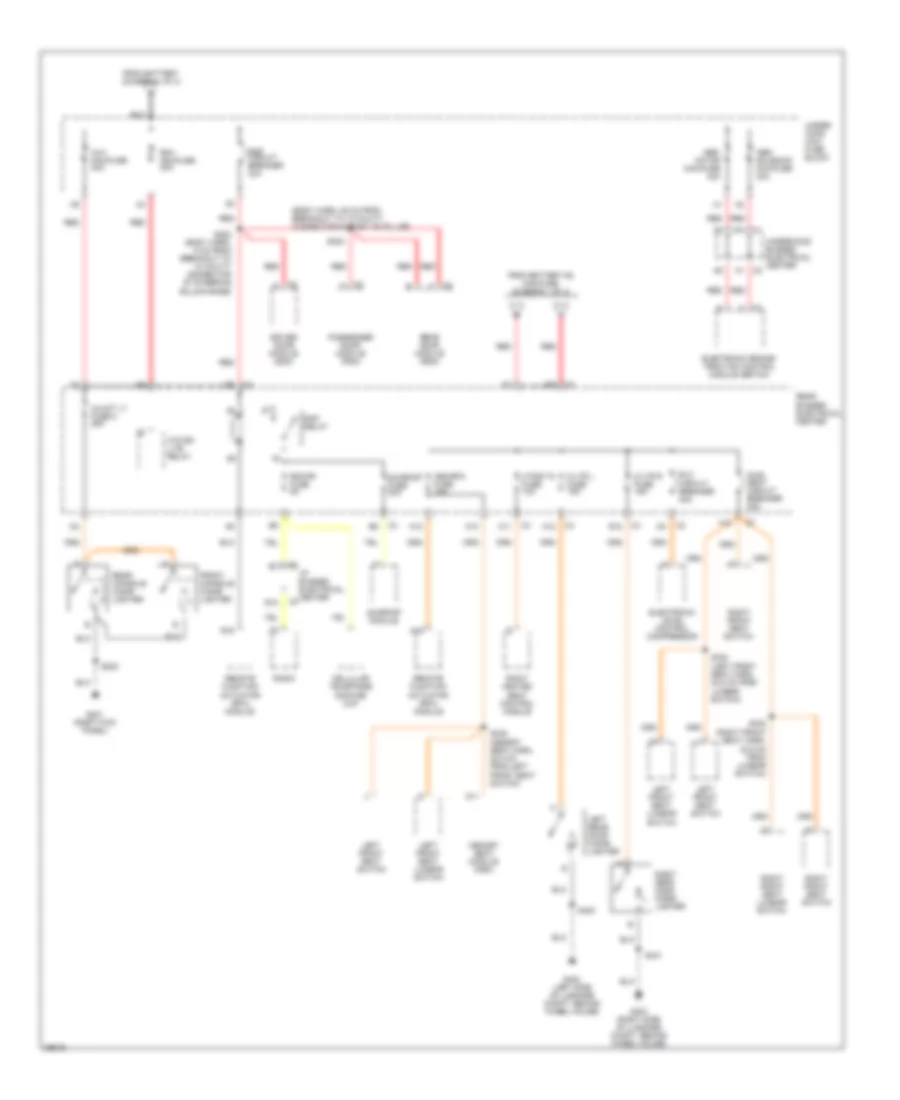
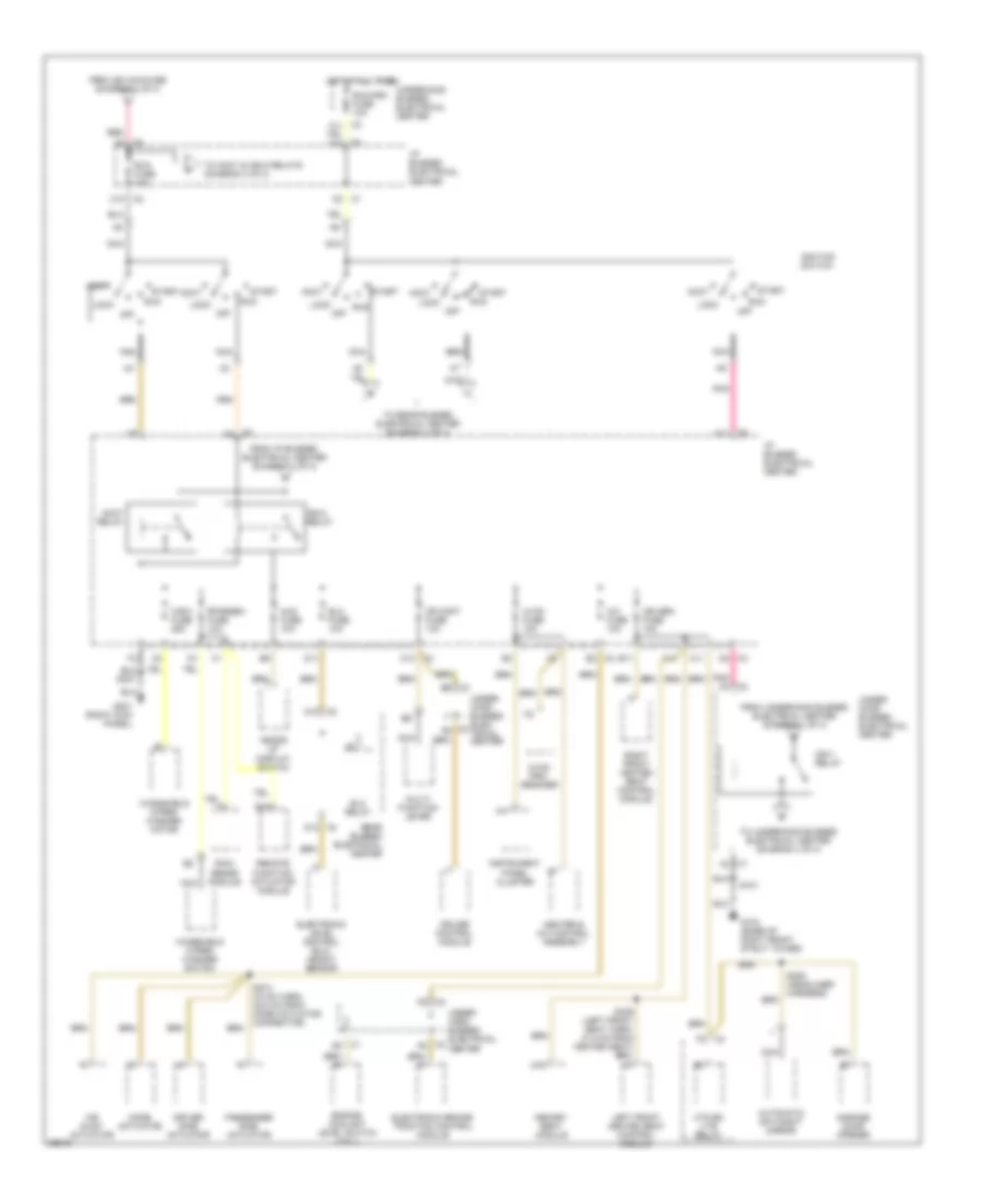
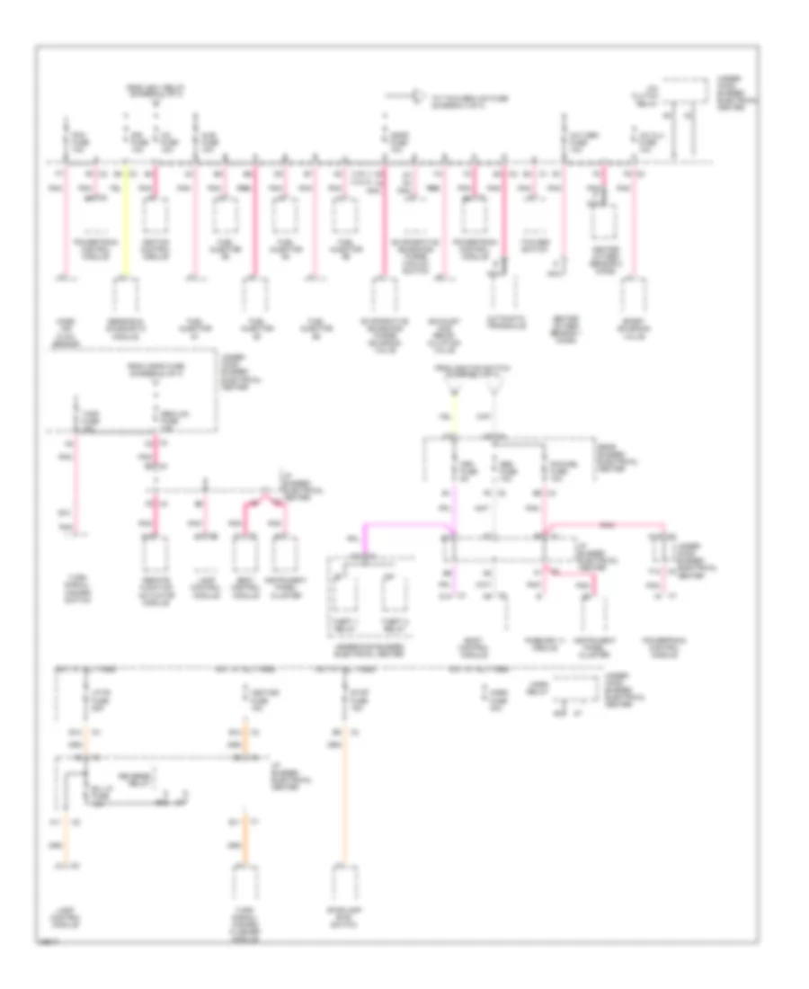
POWER DISTRIBUTION Power Distribution Wiring Diagram (1 of 4) for Buick Park Avenue Ultra 1997 List of elements for Power Distribution Wiring Diagram (1 of 4) for Buick Park Avenue Ultra 1997: 63 A10 c1 A12 Ashtray cigar lighter B10 B12 Batt #1 maxifuse 60a Batt #2 maxifuse 60a Battery Blo mot maxifuse 30a Blower control module Body control module Bose amplifier C/ltr fuse 15a C10 Cd changer Cd/ph fuse 10a Cellular telephone docking cup Cellular telephone rf booster Cool fan #1 maxifuse 30a Cool fan #1 relay Cool fan #2 maxifuse 30a Cool fan #2 relay Cool fan s/p relay Cstr/sbm fuse 10a Data link connector (dlc) Ddm fuse 10a Driver door module (ddm) E11 E12 F/pmp fuse 20a F10 Fuel door release solenoid Fuel pump relay G201 (right kick panel) Generator Hdlp maxifuse 30a Htdstl fuse 10a Hvac programmer I/p bussed electrical center Ign maxifuse 40a Instrument panel cluster Lamp control module Left heated seat module Passenger door module Pdm fuse 10a Radio Rdm fuse 10a Rdo fuse 10a Rear bussed electrical center Rear door module (rdm) Red S217 Sbm fuse 15a Starter solenoid Thft #1 relay Thft maxifuse 30a To ign-1 relay (diagram 3 of 4) To rear bussed electrical center (diagram 2 0f 4) To run fuse (diagram 3 of 4) To underhood maxifuse block (diagram 2 of 4) Trk rel fuse 15a Trunk lid release relay Underhood bussed electrical center Power Distribution Wiring Diagram (2 of 4) for Buick Park Avenue Ultra 1997 List of elements for Power Distribution Wiring Diagram (2 of 4) for Buick Park Avenue Ultra 1997: 65 (body harn, 38 cm from breakout to 10 cavity connector in right "b" pillar) (left front seat harn, 32.5 cm from lumbar switch) (memory seat harn, 22.5 cm from left front seat switch) (right front seat harn, 32.5 cm from lumbar switch) A10 A11 A12 A16 Abs- motor maxifuse 40a Abs- solenoid maxifuse 40a Aux maxifuse 30a Auxot lt fuse 8 25a B12 B16 C/ltr l fuse 15a C/ltr r fuse 15a Cellular telephone docking cup D11 Driver door module (ddm) E12 Elc circuit breaker 30a Electronic brake/ traction control module (ebtcm) Electronic level control compressor F10 From battery #2 maxifuse (diagram 1 0f 4) From battery (diagram 1 0f 4) Front console cigar lighter G201 (right kick panel) G402 (left side of luggage compt, behind wheel house) G403 (right side of luggage compt, behind wheel house) Htd bk lite relay Htdst r fuse 10a I/p bussed electrical center Left front seat lumbar switch Left front seat switch Left rear door cigar lighter Mem/rfa fuse 10a Memory seat module (msm) Passenger door module (pdm) Pwr seat circuit breaker 25a Radio Rap circuit breaker 30a Rap relay Rdo/ph fuse 5a Rear bussed electrical center Rear console cigar lighter Rear door module (rdm) Red Remote function actuator (rfa) module Right front seat lumbar switch Right front seat switch Right heated seat control module Right rear door cigar lighter Run maxifuse 40a S202 (body harn, 5 cm from breakout to 10 cavity connector at steering column base) S208 S300 S330 S338 S400 S401 Sunroof fuse 20a Sunroof module Under- hood maxi fuse block Underhood bussed electrical center Power Distribution Wiring Diagram (3 of 4) for Buick Park Avenue Ultra 1997 List of elements for Power Distribution Wiring Diagram (3 of 4) for Buick Park Avenue Ultra 1997: 88 A/c fuse 10a A11 Accy Accy relay Air inlet actuator Automatic day/night mirror B11 B15 C1 d3 C1 d5 C1 f2 C11 C2 a4 C2 a6 C2 a8 C2 c10 C2 d11 C2 e2 C3 a5 C3 b6 C3 c10 C3 c5 C3 d10 C3 d2 C3 f3 C4 d12 Cr cont fuse 10a Cruise control module D11 D13 Driver side actuator Elc fuse 10a Elc relay Electronic brake/ traction control module Electronic level control (elc) height sensor Engine coolant level switch (vin 1) From i/p bussed electrical center (diagram 3 of 3) From ign maxifuse (diagram 1 of 4) From underhood bussed electrical center (diagram 1 of 4) G103 (base of right front strut tower) G201 (right kick panel) Garage door opener Heads up display switch Heater & a/c control assembly Hot at all times Htd bk lite relay Hud fuse 10a Hvac fuse 10a Hvac pro- grammer I/p bussed electrical center Ign sen fuse 10a Ign-1 relay Ign-3 relay Ignition switch Instrument panel cluster Left front heated seat control module Lock Memory seat module Mode actuator Multi- function lever Nca Nca nca Off Passenger side actuator Pnk Pnk c3 Rain sense module Rear bussed electrical center Red Remote function actuator module Rfarsen fuse 10a Right front heated seat control module Run Run fuse 10a Run/crk fuse 10a S101 S274 (hvac harn, 35.5 cm from mode actuator connector) S305 (headliner harness) Start To accy & ign-3 relays (diagram 3 of 3) To rear bussed electrical center (diagram 4 of 4) To underhood bussed electrical center (diagram 4 of 4) Under- hood bussed elec- trical center Under- hood bussed electrical center Underhood bussed electrical center Windshield wiper/ washer motor Windshield wiper/ washer switch Wsw fuse 25a Power Distribution Wiring Diagram (4 of 4) for Buick Park Avenue Ultra 1997 List of elements for Power Distribution Wiring Diagram (4 of 4) for Buick Park Avenue Ultra 1997: 86 (vin 1) (vin k) A/c clu fuse 10a A/c clutch relay A11 A12 A15 Automatic transaxle B/u lp fuse 10a B10 B12 Body control module Boost solenoid valve C1 c7 C1 d14 C1 e4 C2 a7 C2 a9 C2 e4 C2 f5 C2 f6 C3 a10 C3 c2 C3 e3 C3 e5 C3 e6 C3 f5 C3i fuse 10a C4 a5 Crk fuse 5a D4 pnk a E11 E12 Evaporative emissions purge solenoid valve Evaporative emissions purge vacuum switch Exhaust gas recir- culation valve F12 From ign-1 relay (diagram 3 of 4) From ignfd fuse (diagram 4 of 4) From ignition switch (diagram 3 of 4) Fuel injector #1 Fuel injector #2 Fuel injector #3 Fuel injector #4 Fuel injector #5 Fuel injector #6 Heated oxygen sensor 1 (ho2s) Heated oxygen sensor 2 (ho2s) Horn fuse 30a Horn relay Hot at all times Hzdt/sg fuse 15a I/p bussed electrical center Ignfd fuse 10a Ignition control module Injr fuse 10a Instrument panel cluster Lamp control module Lp pk fuse 25a Mass air flow sensor Nca Oxy sen fuse 10a Pass-key iii module Pcm fuse 10a Pcm/cru fuse 10a Pnk Pnk d Pnk pnk Powertrain control module Rear bussed electrical center Remote function actuator module Reverse relay Sbm fuse 10a Sbm/lcm fuse 10a Sensing & diagnostic module Sir fuse 10a Stop fuse 15a Stoplamp btsi switch T/sig fuse 10a Tcc/abs switch Theft 1 relay Theft 2 relay To t/s & sbm/lcm fuse (diagram 4 of 4) Turn signal/ hazard flasher module Turn signal/ hazard switch Under- hood bussed electrical center Underhood bussed electrical center
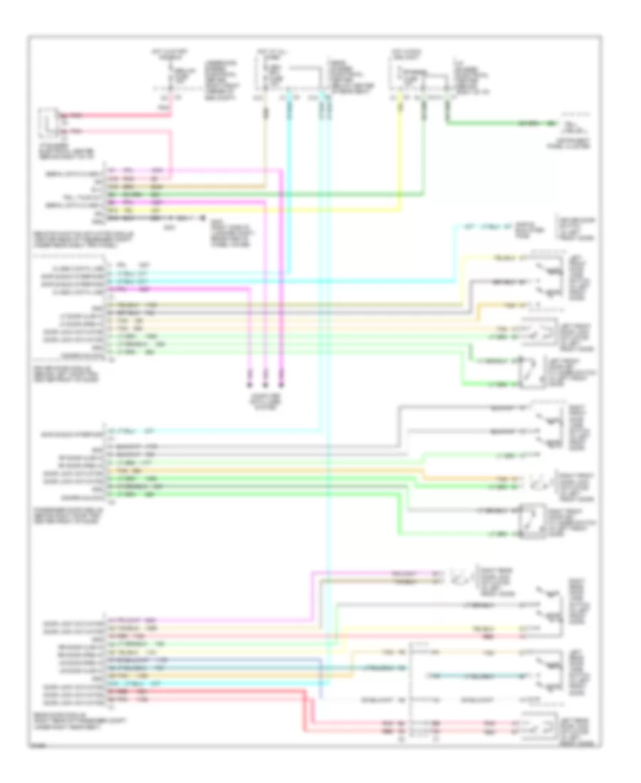
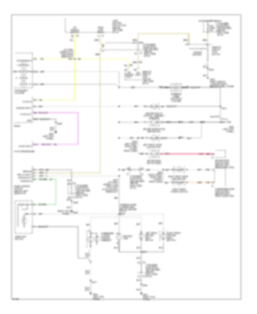
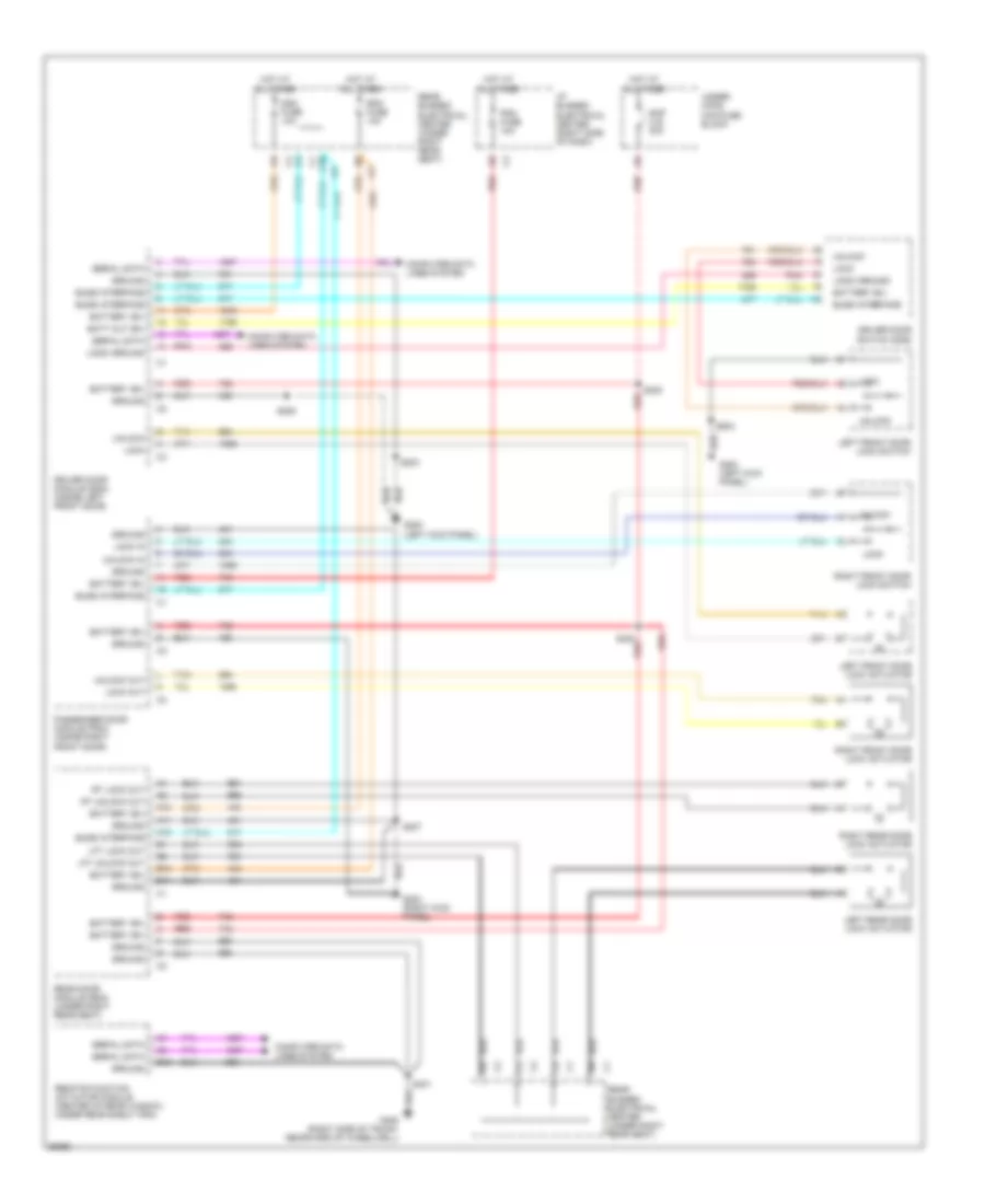
POWER DOOR LOCKS Power Door Lock Wiring Diagram for Buick Park Avenue Ultra 1997 List of elements for Power Door Lock Wiring Diagram for Buick Park Avenue Ultra 1997: 56 A10 A11 A12 B10 B11 B16 Batt out (b+) Battery (b+) Buss interface C10 Computer data lines system Ddm fuse 10a Driver door module (ddm) (inside left front door) Driver door switch (dds) G200 (left kick panel) G203 (right kick panel) Ground Hot at all times I/p bussed electrical center (right side of dash) Left front door lock actuator Left front door lock switch Left rear door lock actuator Lft lock out Lft unlock out Lock Lock Lock in Lock out Logic ground Passenger door module (pdm) (inside right front door) Pdm fuse 10a Pnk Rap c.b. 30a Rdm fuse 10a Rear bussed electrical center (under right rear seat) Rear door module (rdm) (under right rear seat) Red Remote function actuator module (center of rear window, under rear shelf trim) Right front door lock actuator Right front door lock switch Right rear door lock actuator Rt lock out Rt unlock out S202 S203 S205 S207 S300 red S401 S503 Serial data Tan Under- hood maxifuse block Unlock Unlock in Unlock out
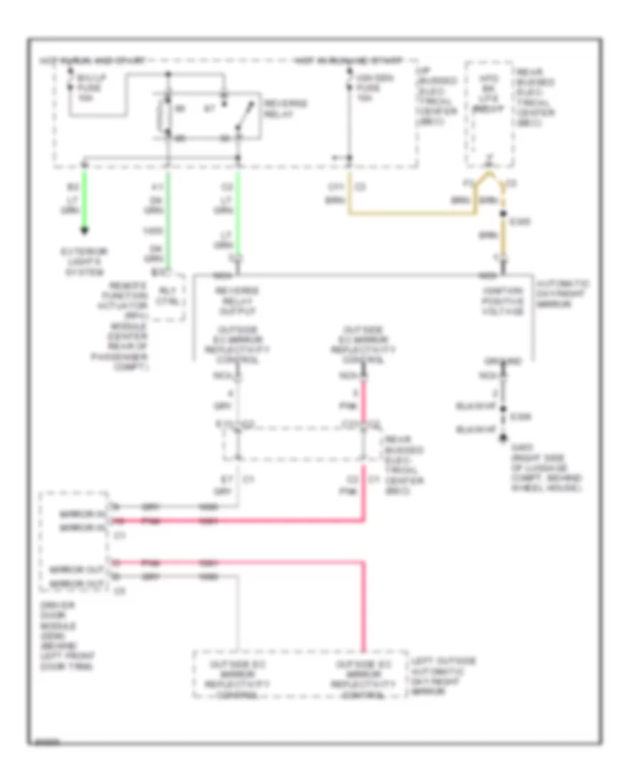
POWER MIRRORS Electrochromic Mirror Wiring Diagram for Buick Park Avenue Ultra 1997 List of elements for Electrochromic Mirror Wiring Diagram for Buick Park Avenue Ultra 1997: 30 Automatic day/night mirror B/u lp fuse 10a C mirror out C11 c2 C11 c3 C2 c1 D mirror out Driver door module (ddm) (behind left front door trim) E11 c2 E7 c1 Exterior lights system G403 (right side of luggage compt, behind wheel house) Ground Hot in run and start Htd bk lite relay I/p bussed elec- trical center (bec) Ign sen fuse 10a Ignition positive voltage Left outside automatic day/night mirror Mirror in Nca Outside ec mirror reflectivity control Pnk Rear bussed elec- trical center (bec) Remote function actuator (rfa) module (center rear of passenger compt) Reverse relay Reverse relay output Rly ctrl S305 S306
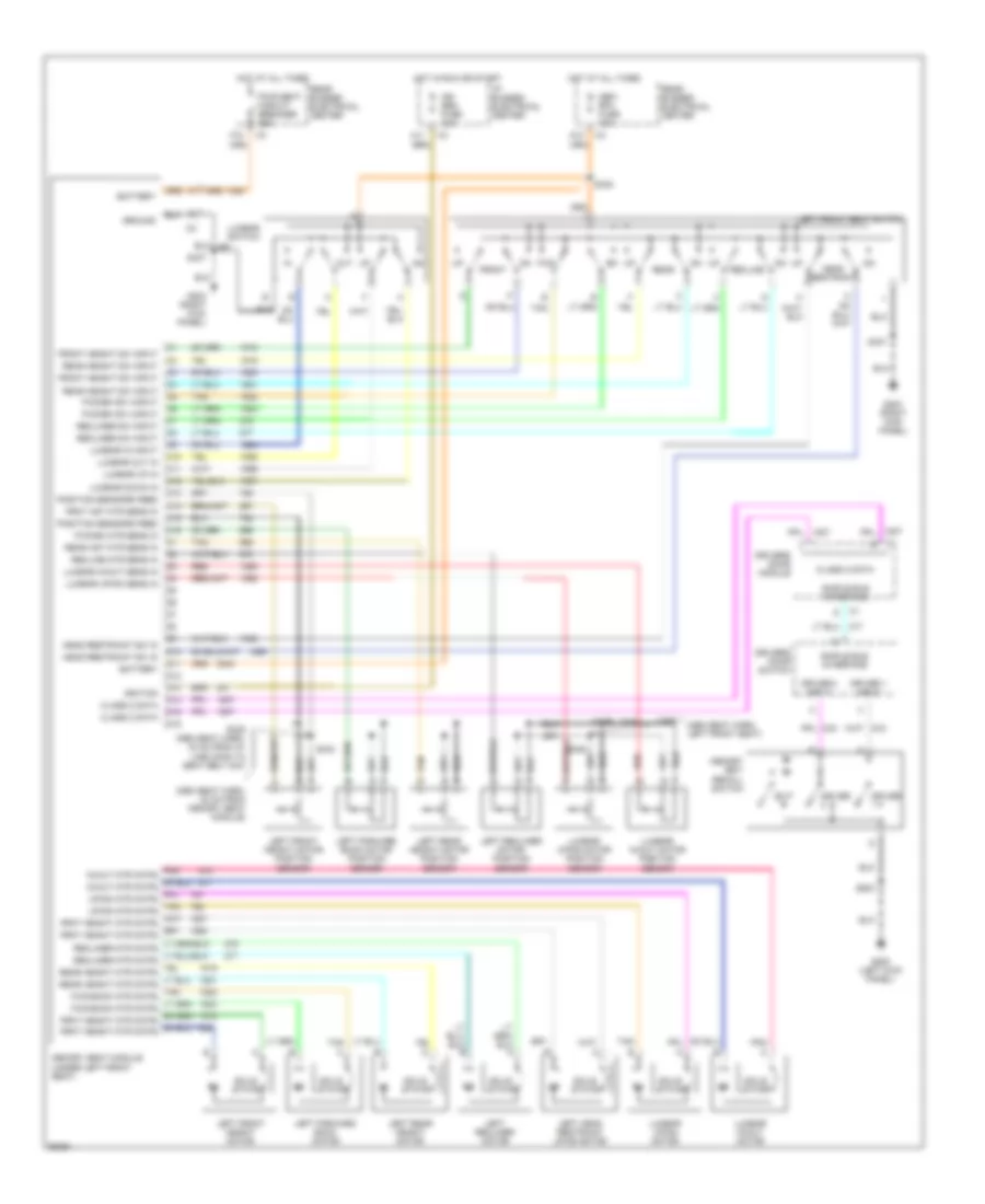
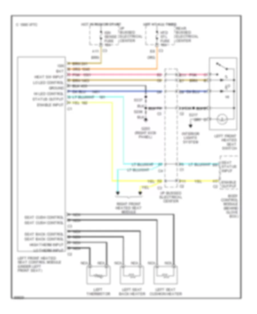
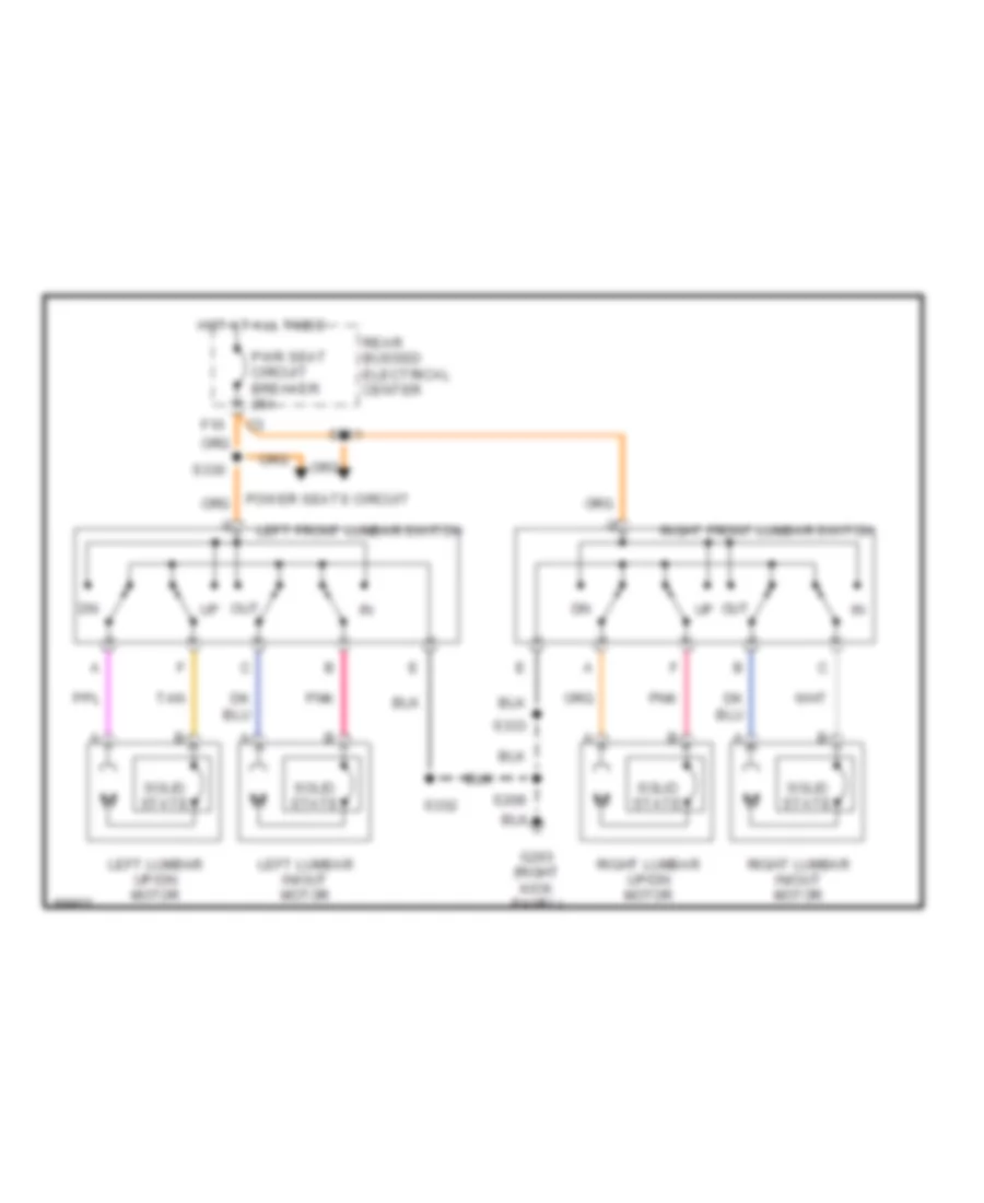
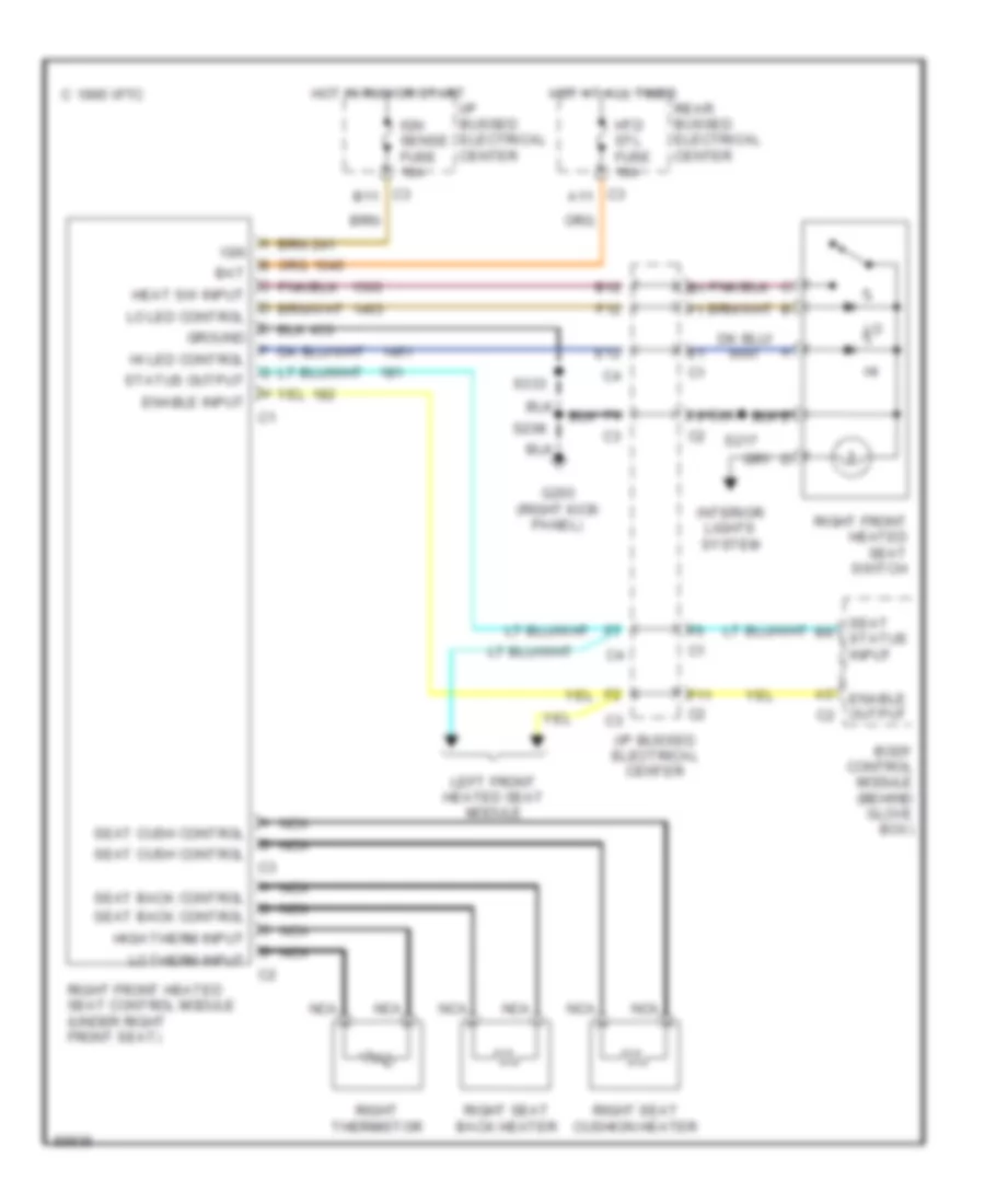
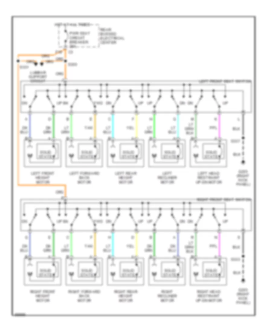
POWER SEATS Driver Heated Seat Wiring Diagram for Buick Park Avenue Ultra 1997 List of elements for Driver Heated Seat Wiring Diagram for Buick Park Avenue Ultra 1997: 41 (right kick 1995 vftc c Bat Body control module (behind glove box) C3 a11 C3 e8 E11 Enable input Enable output F11 G203 Ground Heat sw input Hi led control High therm input Hot at all times Hot in run or start Htd stl fuse 10a I/p bussed electrical center Ign Ign sense fuse 10a Interior lights system Left front heated seat control module (under left front seat) Left front heated seat switch Left seat back heater Left seat cushion heater Left thermistor Lo led control Lo therm input Nca Panel) Pnk Rear bussed electrical center Right front heated seat module S208 S217 S337 Seat back control Seat cush control Seat status input Status output Lumbar Wiring Diagram for Buick Park Avenue Ultra 1997 List of elements for Lumbar Wiring Diagram for Buick Park Avenue Ultra 1997: 21 F10 G203 (right kick panel) Hot at all times Left front lumbar switch Left lumbar in/out motor Left lumbar up/dn motor Out Pnk Power seats circuit Pwr seat circuit breaker 25a Rear bussed electrical center Right front lumbar switch Right lumbar in/out motor Right lumbar up/dn motor S208 S330 S331 S332 S333 Solid state Tan Passenger Heated Seat Wiring Diagram for Buick Park Avenue Ultra 1997 List of elements for Passenger Heated Seat Wiring Diagram for Buick Park Avenue Ultra 1997: 42 (right kick 1995 vftc c B12 Bat Body control module (behind glove box) C3 a11 C3 b11 E12 Enable input Enable output F11 F12 G203 Ground Heat sw input Hi led control High therm input Hot at all times Hot in run or start Htd stl fuse 10a I/p bussed electrical center Ign Ign sense fuse 10a Interior lights system Left front heated seat module Lo led control Lo therm input Nca Panel) Rear bussed electrical center Right front heated seat control module (under right front seat) Right front heated seat switch Right seat back heater Right seat cushion heater Right thermistor S208 S217 S333 Seat back control Seat cush control Seat status input Status output Power Seats Wiring Diagram for Buick Park Avenue Ultra 1997 List of elements for Power Seats Wiring Diagram for Buick Park Avenue Ultra 1997: 25 F10 Fwd G203 (right kick panel) Hot at all times Left forward back motor Left front height motor Left front seat switch Left head restraint up-dn motor Left rear height motor Left recliner motor Lumbar support circuit Pwr seat circuit breaker 25a Rear bussed electrical center Right forward back motor Right front height motor Right front seat switch Right head restraint up-dn motor Right rear height motor Right recliner motor S300 S331 S333 S337 Solid state Tan
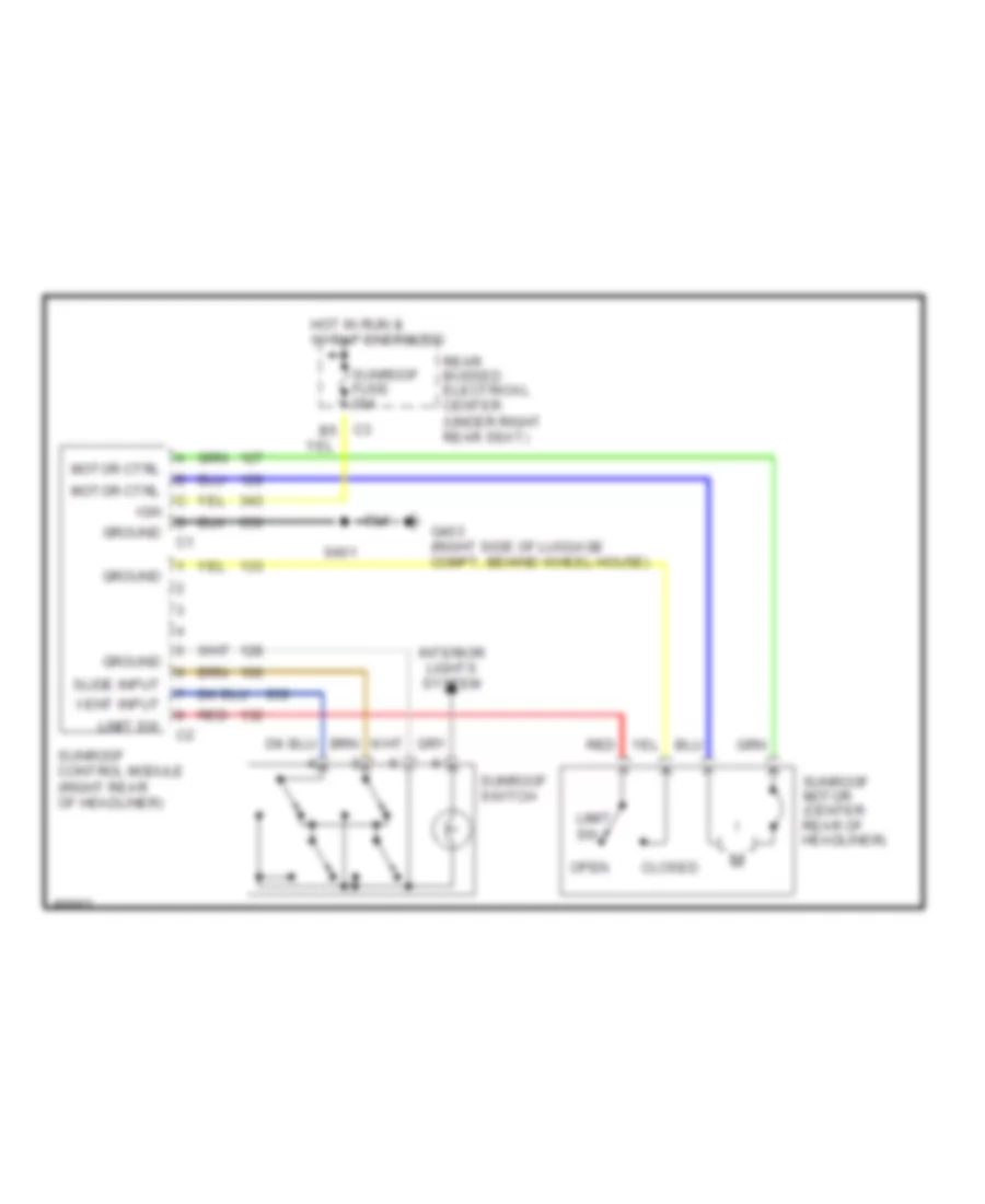
POWER TOP/SUNROOF Sunroof Wiring Diagram for Buick Park Avenue Ultra 1997 List of elements for Sunroof Wiring Diagram for Buick Park Avenue Ultra 1997: 18 Closed G403 (right side of luggage compt, behind wheel house) Ground Hot in run & w/ rap energized Ign Interior lights system Limit sw Motor ctrl Open Rear bussed electrical center (under right rear seat) Red S401 Slide input Sunroof control module (right rear of headliner) Sunroof fuse 20a Sunroof motor (center rear of headliner) Sunroof switch Vent input
POWER WINDOWS Power Window Wiring Diagram for Buick Park Avenue Ultra 1997 List of elements for Power Window Wiring Diagram for Buick Park Avenue Ultra 1997: 59 (right side of luggage compt behind wheelhouse) A10 A11 A12 B10 B11 Battery (b+) C10 C8 c4 Class 2 Computer data lines system Ddm fuse 10a Down Down input Driver door module (behind left door trim) Driver door switch E12 Ecb F12 F5 c1 G200 (left kick panel) G203 (right kick panel) G403 Ground Hot at all times I/p bussed electrical center (right side of i/p) Interior lights system Lamp feed Left front window motor Left rear window motor Left rear window switch Lf win ctrl Logic pwr Lr win ctrl Passenger door module (behind right door trim) Pdm fuse 10a Pnk Rap circuit breaker 30a Rdm fuse 10a Rear bussed electrical center (under right rear seat) Rear door module (under right rear seat) Red Return Rf win ctrl Right front window motor Right front window switch Right rear window motor Right rear window switch Rr win ctrl S202 S203 S205 S207 S208 S300 S401 Sbi Underhood maxi fuse block (right front of engine compt) Up input
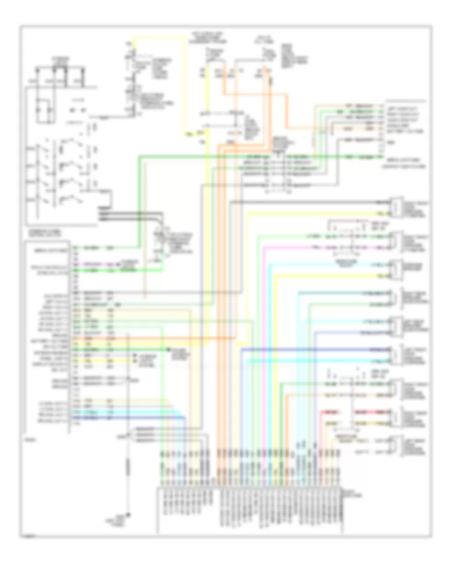
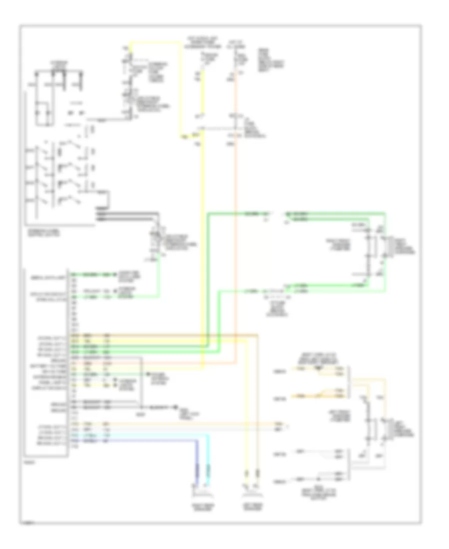
RADIO Radio Wiring Diagrams, without Amplifier for Buick Park Avenue Ultra 1997 List of elements for Radio Wiring Diagrams, without Amplifier for Buick Park Avenue Ultra 1997: 71 (body harn, 24 cm from left dash-to- eng compt grommet) s219 1997-98 1999-00 Antenna enable B12 Battery voltage C2 f10 Computer data lines system Diplay dim sig out Display dim sig in E10 E11 E12 E13 E14 E15 E16 E3 c3 F10 F11 F12 F13 F14 F15 F16 G200 (left kick panel) Ground Hot at all times Hot in run, acc or retained accessory power I/p fuse block (behind glove box) Ign voltage Inflatable restraint steering wheel module coil Interior lights system Left front speaker (midrange) Left front speaker (tweeter) Left rear speaker Lf chnl out (+) Lf chnl out (-) Lr chnl out (+) Lr chnl out (-) Nca Panel lamp in Power antenna system Radio Rdo fuse 10a Rdo/ph fuse 5a Rear fuse block (below right side of rear seat) Rf chnl out (+) Rf chnl out (-) Right front speaker (midrange) Right front speaker (tweeter) Right rear speaker Rr chnl out (+) Rr chnl out (-) S209 S218 (body harn, 27 cm from park brake switch) Serial data uart Steering column fuse holder (1998-00) Steering wheel control switch Strg whl ctlr Sw1 Sw2 Sw3 Sw4 Sw5 Sw6 Sw7 Sw8 Switch fuse 2a Tan Tan b
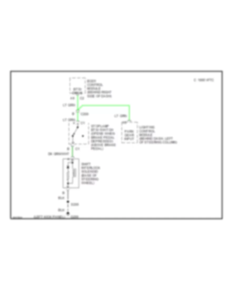
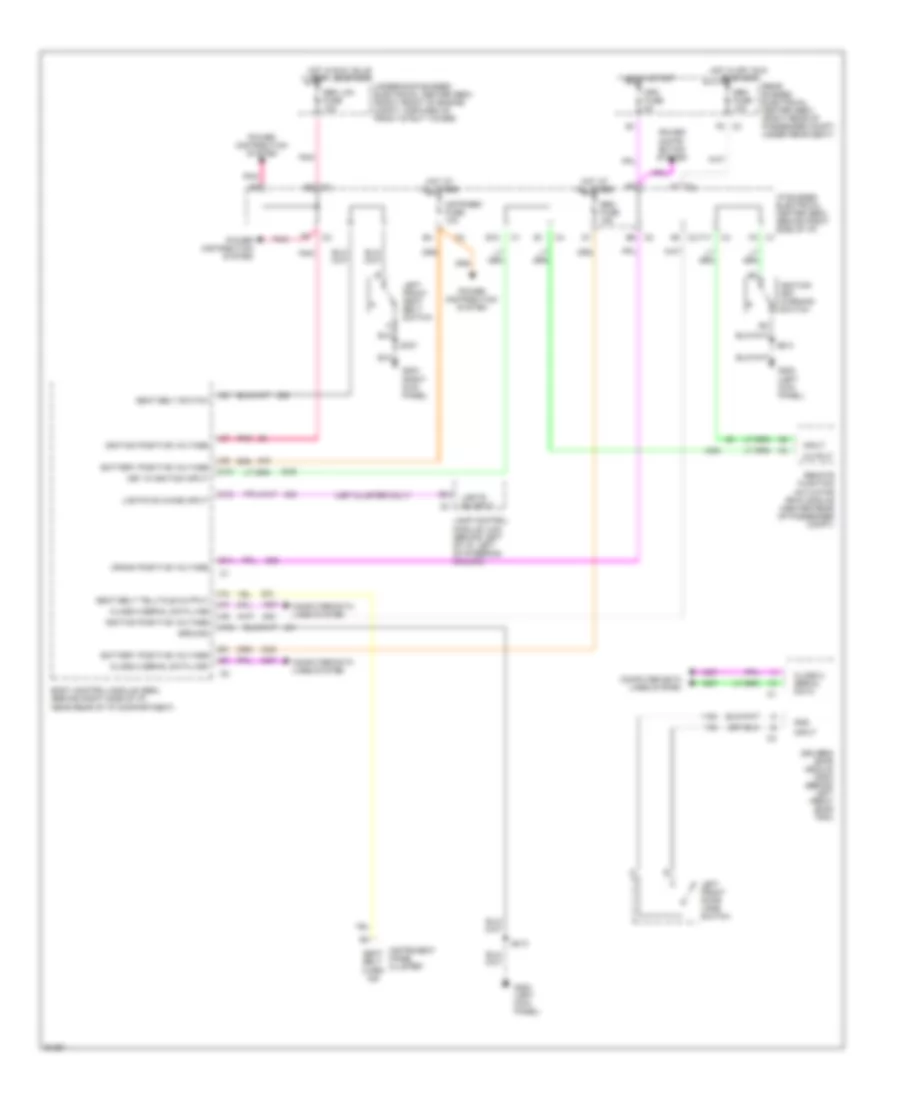
SHIFT INTERLOCKS Shift Interlock Wiring Diagram for Buick Park Avenue Ultra 1997 List of elements for Shift Interlock Wiring Diagram for Buick Park Avenue Ultra 1997: 11 (left kick panel) 1995 vftc c Body control module (behind right side of dash) Btsi drive C200 G200 Lighting control module (behind dash, left of steering column) Park gear input S205 Shift interlock solenoid (base of steering wheel) Stoplamp btsi switch (opens when brake pedal depressed) (above brake pedal)
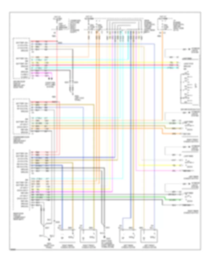
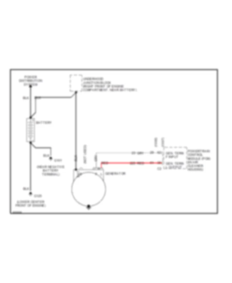
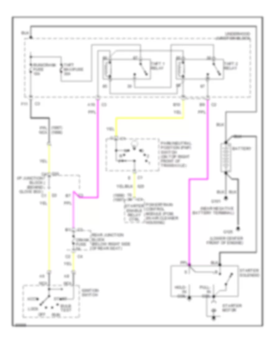
STARTING/CHARGING Charging Wiring Diagram for Buick Park Avenue Ultra 1997 List of elements for Charging Wiring Diagram for Buick Park Avenue Ultra 1997: 15 (1997) (1998) (lower center front of engine) (not used) Bat Battery G101 G125 Gen. term. f input Gen. term. l output Generator l Power distribution system Powertrain control module (pcm) (in air cleaner housing) Red Underhood junction block (right front of engine compartment, near battery) Starting Wiring Diagram for Buick Park Avenue Ultra 1997 List of elements for Starting Wiring Diagram for Buick Park Avenue Ultra 1997: 33 (1998) (1998) (1997) (lower center front of engine) A10 Accy B10 Battery Bulb test Crank fuse 5a D10 F11 G101 G125 Hold- in coil I/p junction block (behind glove box) Ignition switch Lock Nca Off Park/neutral position (pnp) switch (on top right front of transaxle) Powertrain control module (pcm) (in air cleaner housing) Pull- in coil Rear junction block (below right side of rear seat) Run Run/crank fuse 10a Start Starter enable relay ctrl Starter motor Starter solenoid Thft 1 relay Thft 2 relay Thft maxifuse 30a Underhood junction block
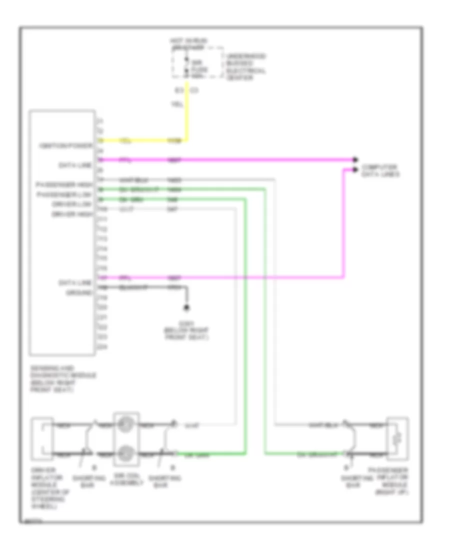
SUPPLEMENTAL RESTRAINTS Supplemental Restraint Wiring Diagram for Buick Park Avenue Ultra 1997 List of elements for Supplemental Restraint Wiring Diagram for Buick Park Avenue Ultra 1997: 21 A nca Bar Computer data lines Data line Driver high Driver inflator module (center of steering wheel) Driver low E3 c3 G301 (below right front seat) Ground Hot in run or start Ignition power Nca Passenger high Passenger inflator module (right i/p) Passenger low Sensing and diagnostic module (below right front seat) Shorting Sir coil assembly Sir fuse 10a Underhood bussed electrical center
TRANSMISSION
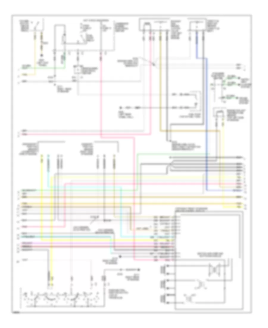
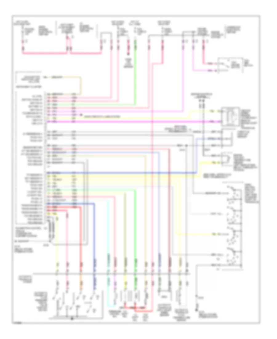
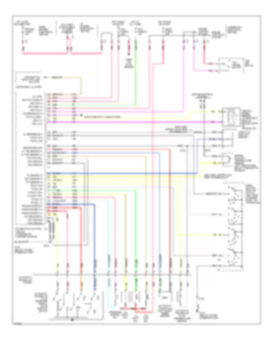
3.8L 3.8L (VIN 1), Transmission Wiring Diagram, 4T65-E for Buick Park Avenue Ultra 1997 List of elements for 3.8L (VIN 1), Transmission Wiring Diagram, 4T65-E for Buick Park Avenue Ultra 1997: 73 (eng harn, approx 48 cm from pcm breakout) (eng harn, approx 6 cm from tps breakout) 1-2 shift sol 2-3 shift sol 5v reference a A/t iss sensor hi A/t iss sensor lo A12 Anti-theft & instrument cluster systems Automatic transaxle (4t65-e) Automatic transaxle fluid pressure manual valve position switch Automatic transaxle fluid temperature sensor Automatic transaxle input shaft speed sensor Battery in Computer data lines system Cruise control sysyem Data class ii E12 Ect sensor in Engine controls system Engine coolant temperature sensor (left rear of eng below thermostat housing) F12 G119 (below power steering pump) Hot at all times Hot in off, run or start Hot in run or start I/p bussed electrical center Ignfd fuse 8 10a Ignition in Ignition wake up Instrument cluster Malfunction indicator lamp (mil) ctrl Mass air flow sensor Mil ctrl Park/ neutral position switch (left side of engine compt on transaxle) Pc sol hi Pc sol lo Pcm fuse 23 10a Pcm fuse 6 10a Pcm ground Pcm/cru fuse 9 10a Pnk Powertrain control module (in engine air cleaner housing) Pressure control sol Rear bussed electrical center Red Rev S103 S105 S106 S108 Sensor return Tan Tcc pwm sol Tcc release Tcc release in Tcc/ abs switch Tcc/ cruise switch Tcc/brake sw in Tft sensor in Throttle position sensor Tp sensor in Tr sw in-a Tr sw in-b Tr sw in-p Tr sw inc Trans range a in Trans range b in Trans range c in Underhood electrical center Vehicle speed sensor (lower right rear of engine compt on transaxle) Vss hi in Vss lo in 3.8L (VIN K), Transmission Wiring Diagram, 4T65-E for Buick Park Avenue Ultra 1997 List of elements for 3.8L (VIN K), Transmission Wiring Diagram, 4T65-E for Buick Park Avenue Ultra 1997: 73 (eng harn, approx 48 cm from pcm breakout) (eng harn, approx 6 cm from tps breakout) 1-2 shift sol 2-3 shift sol 5v reference a A/t iss sensor hi A/t iss sensor lo A12 Anti-theft & instrument cluster systems Automatic transaxle (4t65-e) Automatic transaxle fluid pressure manual valve position switch Automatic transaxle fluid temperature sensor Automatic transaxle input shaft speed sensor Battery in Computer data lines system Cruise control sysyem Data class ii E12 Ect sensor in Engine controls system Engine coolant temperature sensor (left rear of eng below thermostat housing) F12 G119 (below power steering pump) Hot at all times Hot in off, run or start Hot in run or start I/p bussed electrical center Ignfd fuse 8 10a Ignition in Ignition wake up Instrument cluster Malfunction indicator lamp (mil) ctrl Mass air flow sensor Mil ctrl Park/ neutral position switch (left side of engine compt on transaxle) Pc sol hi Pc sol lo Pcm fuse 23 10a Pcm fuse 6 10a Pcm ground Pcm/cru fuse 9 10a Pnk Powertrain control module (in engine air cleaner housing) Pressure control sol Rear bussed electrical center Red Rev S103 S105 S106 S108 Sensor return Tan Tcc pwm sol Tcc release Tcc release in Tcc/ abs switch Tcc/ cruise switch Tcc/brake sw in Tft sensor in Throttle position sensor Tp sensor in Tr sw in-a Tr sw in-b Tr sw in-p Tr sw inc Trans range a in Trans range b in Trans range c in Underhood electrical center Vehicle speed sensor (lower right rear of engine compt on transaxle) Vss hi in Vss lo in
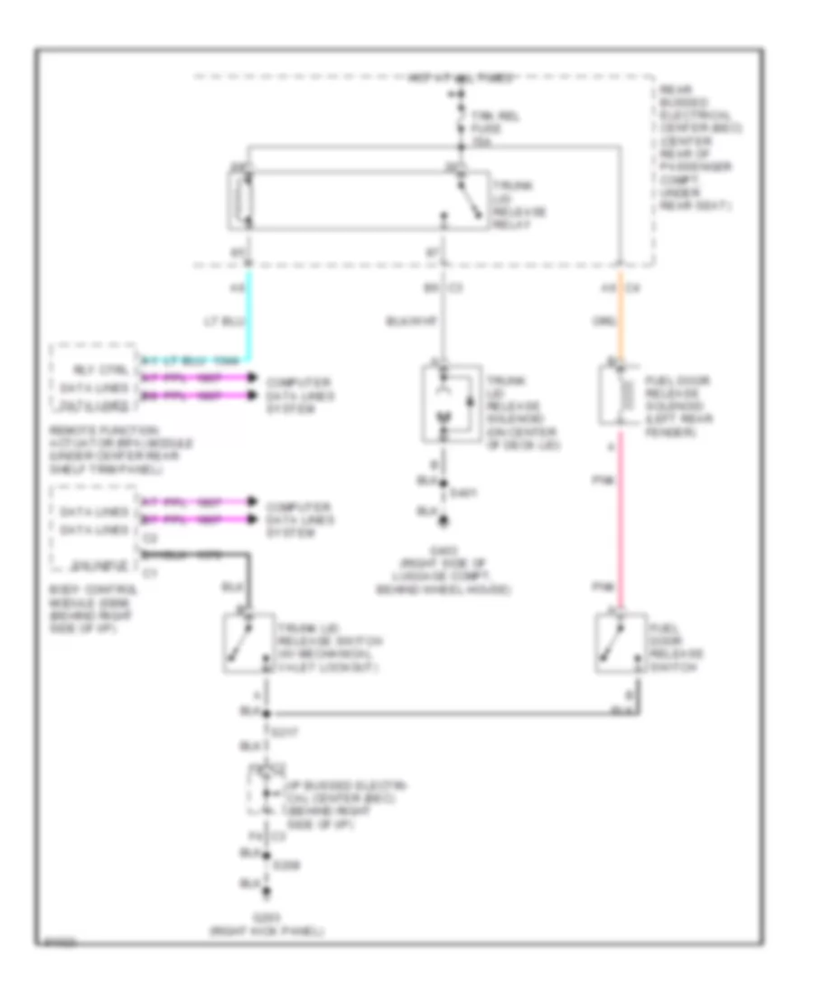
TRUNK, TAILGATE, FUEL DOOR Trunk & Fuel Door Release Wiring Diagram for Buick Park Avenue Ultra 1997 List of elements for Trunk & Fuel Door Release Wiring Diagram for Buick Park Avenue Ultra 1997: 26 B6 c3 Body control module (sbm) (behind right side of i/p) C2 f9 C4 a6 Computer data lines system D11 Data lines F4 c3 Fuel door release solenoid (left rear fender) Fuel door release switch G203 (right kick panel) G403 (right side of luggage compt, behind wheel house) Hot at all times I/p bussed electri- cal center (bec) (behind right side of i/p) Pnk Rear bussed electrical center (bec) (center rear of passenger compt, under rear seat) Remote function actuator (rfa) module (under center rear shelf trim panel) Rly ctrl S208 S217 S401 Sw input Trk rel fuse 15a Trunk lid release relay Trunk lid release solenoid (on center of deck lid) Trunk lid release switch (w/ mechanical valet lockout)
WARNING SYSTEMS Warning System Wiring Diagrams for Buick Park Avenue Ultra 1997 List of elements for Warning System Wiring Diagrams for Buick Park Avenue Ultra 1997: 53 (ub7 cluster only) A12 A7 c3 B12 Battery positive voltage Body control module (sbm) (behind right side of i/p, near rear of i/p compartment) C10 C12 Class 2 serial data Class 2 serial data line Computer data lines system Crank positive voltage Crk fuse 5a Cstr/sbm fuse 10a D14 Driver's door module (ddm) (behind left front door trim) E5 c3 F11 F5 c3 G200 (left kick panel) G203 (right kick panel) Gnd Ground Hot at all times Hot in off, run or start Hot in run, bulb test, or start Hot in start I/p bussed electrical center (bec) (behind right side of i/p) Ignition key warning switch Ignition positive voltage Input Instrument panel cluster Key in ignition input Lamp control module (lcm) (behind left of i/p, left of steering column) Left front door jamb switch Left front seat belt switch Lights on chime input Lights on input Output Pnk Power distri- bution system Power distribution system Rear bussed electrical center (bec) (right rear of passenger compt, under rear seat) Remote function actuator (rfa) module (center rear of passenger compt) S213 S337 Sbm fuse 10a Sbm fuse 15a Sbm lcm fuse 10a Seat belt switch Seat belt telltale output Seat belt warn ind Underhood bussed electrical center (bec) (right front of engine compt, forward of front strut tower)
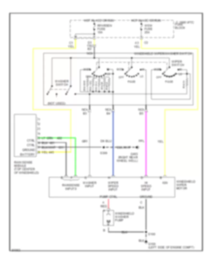
WIPER/WASHER Wiper/Washer Wiring Diagram for Buick Park Avenue Ultra 1997 List of elements for Wiper/Washer Wiring Diagram for Buick Park Avenue Ultra 1997: 29 (not used) 1995 vftc c fuse block Battery Ctrl G100 (left side of engine compt) G403 (right rear wheel well) Ground Hi speed input Hot in acc or run Ign Mist Nca Off Pulse Pump ctrl Rain sense module (top center of windshield) Rainsense inputs Red Rfarsen fuse 10a S100 S306 Washer input Washer switch Windshield washer pump Windshield wiper motor Windshield wiper/washer switch Wiper speed input Wiper switch Wsw fuse 25a