AIR CONDITIONING
Air Conditioning Wiring Diagrams for Chevrolet Beretta 1996

List of elements for Air Conditioning Wiring Diagrams for Chevrolet Beretta 1996:
- (l4 vin 4)
- (left front of engine)
- (v6 vin m)
- +5v
- A/c clutch diode
- A/c compressor clutch
- A/c compressor control relay (right front of engine compartment on relay bracket)
- A/c request
- A/c sensor (right front of engine compartment)
- Bi-lv
- Blend
- Blower motor
- Blower motor relay (right rear of engine compartment)
- Blower resistors (rear of engine compartment)
- Blower switch
- C 1995 vftc
- C tan
- Coolant fan
- Def
- Engine coolant temperature sender/switch (rear of engine)
- Fan control relay (lower left rear of engine)
- Fuse 20a
- Fuse 25a
- Fuse block
- G110 (left front of engine/transaxle)
- G129 (on transaxle stud)
- Heater-a/c control assembly
- Hot at all times
- Hot in run
- Hot in run, bulb test or start
- Htr
- L4 vin 4
- Max
- Mode switch
- Norm
- Off
- Pnk
- Powertrain control module (behind right side of i/p)
- Red
- Relay control
- Sensor ground
- Sensor input
- Solid state
- Tan
- Temperature selector
- Temperature valve motor (left side of steering column brace)
- V6 vin m
- Vent
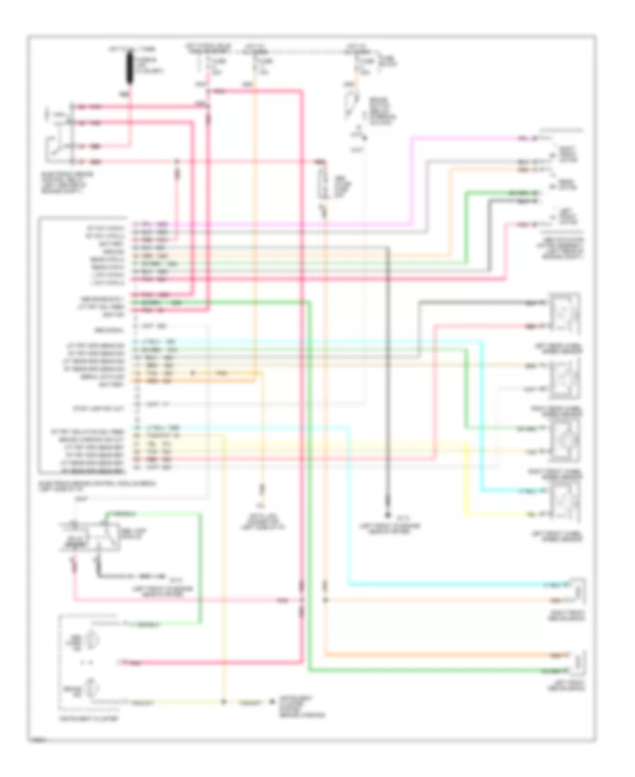
ANTI-LOCK BRAKES
Anti-lock Brake Wiring Diagrams for Chevrolet Beretta 1996
List of elements for Anti-lock Brake Wiring Diagrams for Chevrolet Beretta 1996:
- (left front of engine near starter)
- Abs actuator motor assembly (left rear of engine compt.)
- Abs enable rly
- Abs inline fuse 20a
- Abs lamp module
- Abs signal
- Abs warn ind
- B pnk
- Battery
- Brake ind
- Brake switch (below steering column)
- Brake warning ind out
- Data link connector (left side of i/p)
- Electronic brake control module (ebcm) (left side of i/p)
- Electronic brake control relay (left center of engine compt.)
- Fuse 15a
- Fuse 20a
- Fuse block
- G110
- Ground
- Hot at all times
- Hot in run, bulb test or start
- Ignition
- Instrument cluster
- Instrument cluster system (brake warning)
- L fnt mtr-hi
- L fnt mtr-lo
- Left front abs solenoid
- Left front motor
- Left front wheel speed sensor
- Left rear wheel speed sensor
- Lft frt sol feed
- Lft frt spd sens ret
- Lft frt spd sens sig
- Lft rear spd sens ret
- Lft rear spd sens sig
- Pnk
- Rear motor
- Rear mtr-hi
- Rear mtr-lo
- Red
- Right front abs solenoid
- Right front motor
- Right front wheel speed sensor
- Right rear wheel speed sensor
- Rt fnt mtr-hi
- Rt fnt mtr-lo
- Rt frt isolation sol feed
- Rt frt spd sens ret
- Rt frt spd sens sig
- Rt rear spd sens ret
- Rt rear spd sens sig
- Serial data sig
- Solid state
- Stop lamp sw out
- Tan
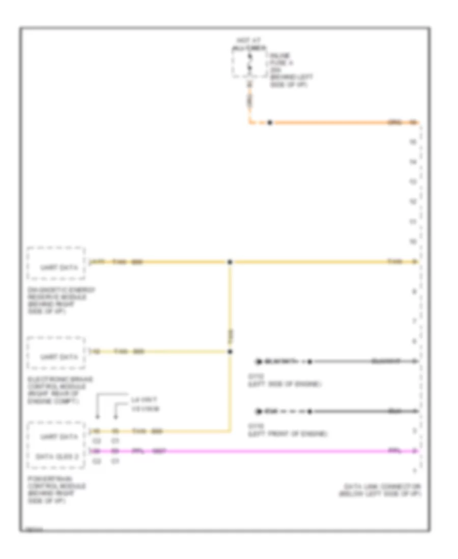
COMPUTER DATA LINES
Computer Data Lines for Chevrolet Beretta 1996
List of elements for Computer Data Lines for Chevrolet Beretta 1996:
- A11
- Data clss 2
- Data link connector (below left side of i/p)
- Diagnostic energy reserve module (behind right side of i/p)
- Electronic brake control module (right rear of engine compt)
- G110 (left front of engine)
- G112 (left side of engine)
- Hot at all times
- Inline fuse a 20a (behind left side of i/p)
- L4 vin t
- Powertrain control module (behind right side of i/p)
- Tan
- Uart data
- V6 vin m
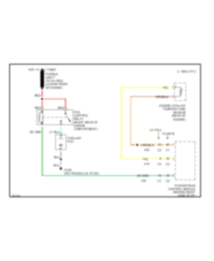
COOLING FAN
Cooling Fan Wiring Diagram for Chevrolet Beretta 1996
List of elements for Cooling Fan Wiring Diagram for Chevrolet Beretta 1996:
- C 1995 vftc
- Coolant fan
- Engine coolant temperature sensor (rear of engine)
- Fan control relay (right rear of engine compartment)
- G129 (on transaxle stud)
- Hot at all times
- L4 vin 4
- Powertrain control module (behind right side of i/p)
- Red
- V6 vin m
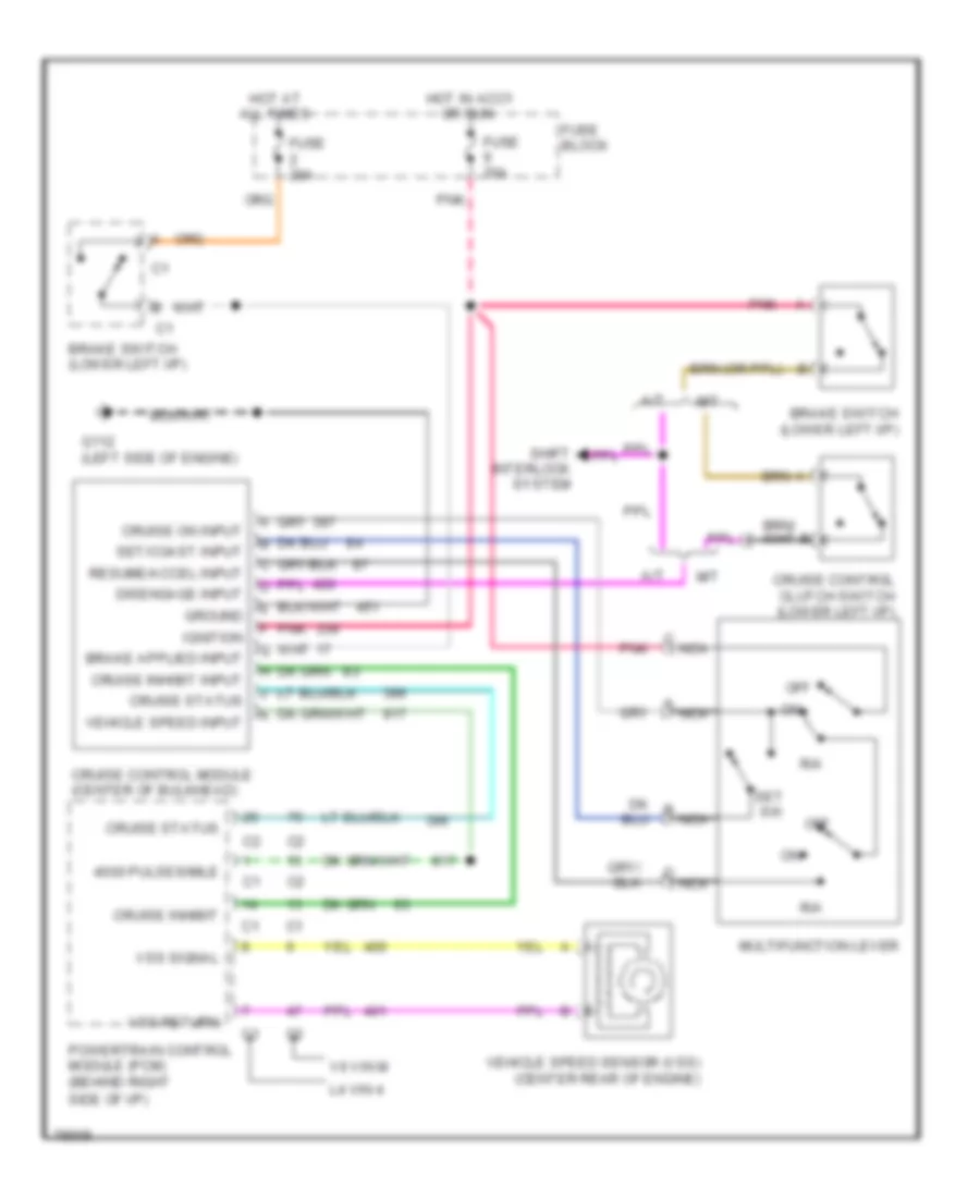
CRUISE CONTROL
Cruise Control Wiring Diagram for Chevrolet Beretta 1996
List of elements for Cruise Control Wiring Diagram for Chevrolet Beretta 1996:
- (center of bulkhead)
- 4000 pulses/mile
- A/t
- All times
- Brake switch (lower left i/p)
- Cruise control clutch switch (lower left i/p)
- Cruise control module
- Cruise inhibit
- Cruise inhibit input
- Cruise on input
- Cruise status
- Disengage input
- Fuse 20a
- Fuse block
- G112 (left side of engine)
- Ground
- Hot at
- Hot in accy
- Ignition
- L4 vin 4
- M/t
- Multifunction lever
- Nca
- Off
- Or run
- Pnk
- Powertrain control module (pcm) (behind right
- R/a
- Resume/accel input
- Set sw
- Set/coast input
- Shift interlock system
- Side of i/p)
- V6 vin m
- Vehicle speed input
- Vehicle speed sensor (vss) (center rear of engine)
- Vss return
- Vss signal
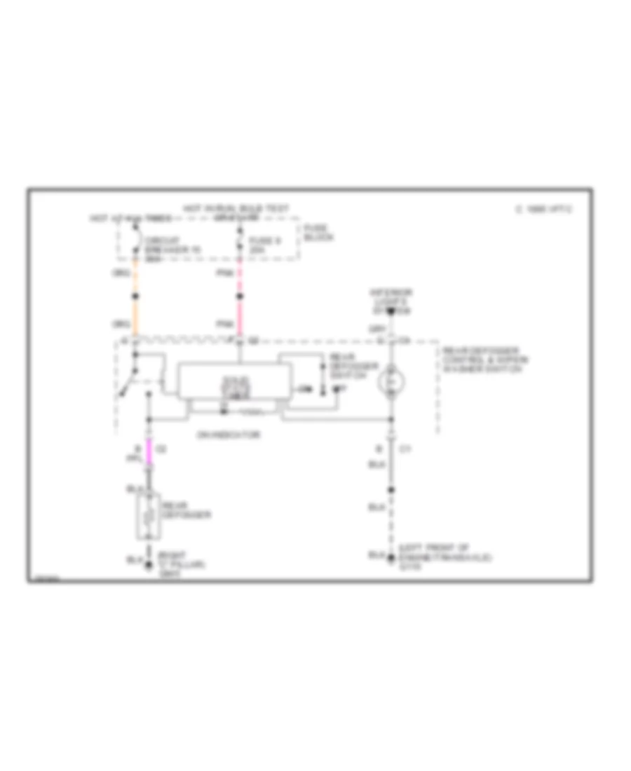
DEFOGGERS
Defogger Wiring Diagram for Chevrolet Beretta 1996
List of elements for Defogger Wiring Diagram for Chevrolet Beretta 1996:
- (left front of engine/transaxle) g110
- (right "c" pillar) g905
- 1995 vftc c
- Circuit breaker 15 30a
- Fuse 9 20a
- Fuse block
- Hot at all times
- Hot in run, bulb test
- Interior lights system
- Off
- On indicator
- Or start
- Pnk
- Rear defogger
- Rear defogger control & wiper/ washer switch
- Rear defogger switch
- Solid state timer
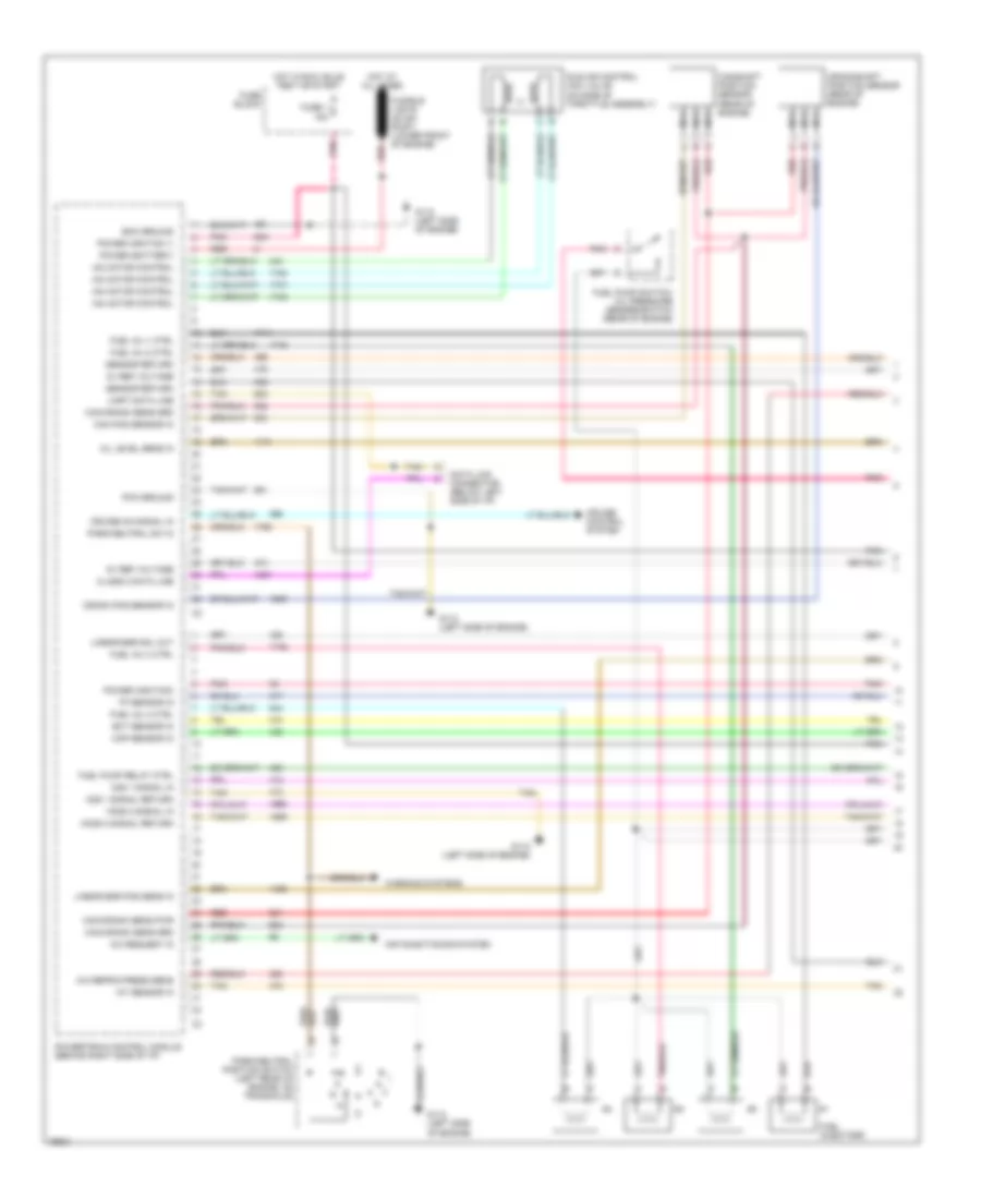
ENGINE PERFORMANCE
2.2L
2.2L (VIN 4), Engine Performance Wiring Diagrams (1 of 3) for Chevrolet Beretta 1996
List of elements for 2.2L (VIN 4), Engine Performance Wiring Diagrams (1 of 3) for Chevrolet Beretta 1996:
- 5v ref voltage
- A/c refrig press sens
- A/c request in
- Air conditioning system
- Cam pos sensor in
- Cam/crank sens grd
- Cam/crank sens pwr
- Camshaft position sensor (rear of engine)
- Class 2 data line
- Crank pos sensor in
- Crankshaft position sensor (rear of engine)
- Cruise control system
- Cruise on signal in
- Data link connector (below left side of i/p)
- Ecm ground
- Ect sensor in
- Fuel inj 1 ctrl
- Fuel inj 2 ctrl
- Fuel inj 3 ctrl
- Fuel inj 4 ctrl
- Fuel injectors
- Fuel pump relay ctrl
- Fuel pump switch/ oil pressure sender/switch (rear of engine)
- Fuse 1 15a
- Fuse block
- Fusible link e (22 ga- rust) (lower front of engine)
- G112 (left side of engine)
- H02s 2 signal in
- Ho2s 2 signal return
- Hot at all times
- Hot in run, bulb test or start
- Iac motor control
- Iat sensor in
- Idle air control (iac) valve (on side of throttle assembly)
- Linear egr pos sens in
- Linear egr sol out
- Map sensor in
- Nca
- O2s 1 signal in
- O2s 1 signal return
- Oil level sens in
- Park/neutral position switch (left rear of engine, on transaxle)
- Park/neutral sw in
- Pcm ground
- Pnk
- Power (battery)
- Power (ignition 1)
- Power (ignition)
- Powertrain control module (behind right side of i/p)
- Red
- Sensor return
- Tan
- Tp sensor in
- Uart data line
- Warning systems
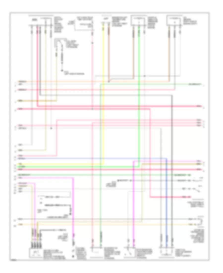
2.2L (VIN 4), Engine Performance Wiring Diagrams (2 of 3) for Chevrolet Beretta 1996
List of elements for 2.2L (VIN 4), Engine Performance Wiring Diagrams (2 of 3) for Chevrolet Beretta 1996:
- A/c sensor (right side of engine compt)
- Digital exhaust gas recirc- ulation solenoid (top of engine)
- Engine coolant temperature sensor (top left front of engine)
- Evap emissions canister purge vacuum switch (rear of of engine)
- Evaporative emissions canister purge solenoid valve (rear of engine)
- F/p-inj fuse 20a
- Fuel pump relay (right side of safety wall)
- Fuel tank unit
- Fuse block
- G112 (left side of engine)
- G116 (left side of safety wall)
- G300 (under driver's seat)
- Heated oxygen sensor 2 (catalyst monitor) (exhaust pipe behind catalytic converter)
- Hot in run, bulb test or start
- Intake air temperature sensor (top left side of engine, on intake air ductwork)
- Manifold absolute pressure sensor (top of engine)
- Nca
- Oil level switch (left front of engine)
- Oxygen sensor 1 (front of engine, in exhaust manifold)
- Pnk
- Tan
- Throttle position sensor (side of throttle body)
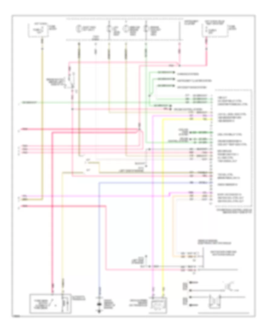
2.2L (VIN 4), Engine Performance Wiring Diagrams (3 of 3) for Chevrolet Beretta 1996
List of elements for 2.2L (VIN 4), Engine Performance Wiring Diagrams (3 of 3) for Chevrolet Beretta 1996:
- (rear of engine) electronic ignition module
- A/c comp relay ctrl
- A/t
- Air conditioning system
- Automatic transaxle
- Brake pedal sw in
- Brake switch (behind left side of i/p)
- Canister purge sol ctrl
- Cool fan relay ctrl
- Coolant temp indic ctrl
- Cooling fans system
- Cruise control system
- Cruise disengage in
- Ecm ground
- Engine coolant temp indic
- Evap vac diag sw in
- Fuse 4 10a
- Fuse 9 20a
- Fuse block
- G112 (left side of engine)
- Hot in run
- Hot in run, bulb test or start
- Ignition amplifier and switching module
- Ignition coil ctrl out
- Instrument cluster
- Instrument cluster system
- Knock sensor (front of engine)
- Knock sensor in
- Low oil level indic
- Low oil level indic ctrl
- M/t
- Mil indic ctrl
- Plugs spark
- Pnk
- Power (ignition 1)
- Powertrain control module (behind right side of i/p)
- Service engine soon indic
- Shift indic (m/t only)
- Tach signal
- Tach signal out
- Tcc sol ctrl
- Third gear switch (closed in third gear)
- Vehicle speed sensor (on transaxle)
- Vss out
- Vss sensor in
- Vss sensor return
- Warning systems
3.1L
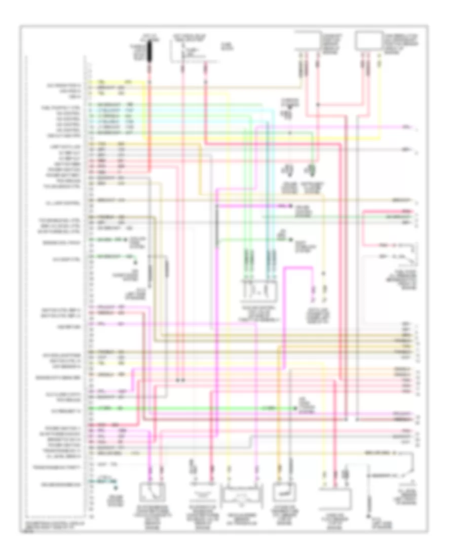
3.1L (VIN M), Engine Performance Wiring Diagrams (1 of 3) for Chevrolet Beretta 1996
List of elements for 3.1L (VIN M), Engine Performance Wiring Diagrams (1 of 3) for Chevrolet Beretta 1996:
- 24x crank pos in
- 5v ref out
- A/c comp ctrl
- A/c request in
- Air cond- itioning system
- Air conditioning system
- Brake/tcc sw in
- Cam pos in
- Camshaft position sensor (rear of engine)
- Cooling fans system
- Cruise control system
- Cruise engaged sig
- Data link connector (under left side of i/p)
- Dlc class 2 data
- Egr valve sol ctrl
- Engine cool fan #1
- Engine data sens grd
- Evap emissions canister purge vacuum diagnostic switch (rear of engine)
- Evap purge diag sw
- Evap purge sol ctrl
- Evaporative emissions canister purge solenoid valve (rear of engine)
- Fuel pump rly ctrl
- Fuel pump/ oil pressure sender/switch (front of engine)
- Fuse 1 15a
- Fuse block
- Fusible link e (22 ga- rust)
- G112 (left side of engine)
- High resolution 24x crankshaft position sensor (front of engine)
- Hot at all times
- Hot in run, bulb test or start
- Iac control
- Icm module bypass
- Idle air control (iac) valve (on side of throttle assembly)
- Ignition ctrl in
- Ignition ctrl ref hi
- Ignition ctrl ref lo
- Ignition feed
- Instrument cluster system
- Intake air temperature (iat) sensor (top of engine)
- Maf sensor in
- Mass air flow sensor (top of engine)
- Mil lamp control
- Oil level sens in
- Oil level sensor (left front of engine)
- Pcm ground
- Pnk
- Power (battery)
- Power (ignition 1)
- Power (ignition)
- Powertrain control module (behind right side of i/p)
- Red
- Shift interlock system
- Tan
- Tcc enable sol ctrl
- Tcc solenoid ctrl
- Trans range sw 'a'
- Trans range sw parity
- Uart data link
- Vehicle speed sensor (on transaxle)
- Vss in
- Vss out-4000 ppm
- Vss return
- Warning systems
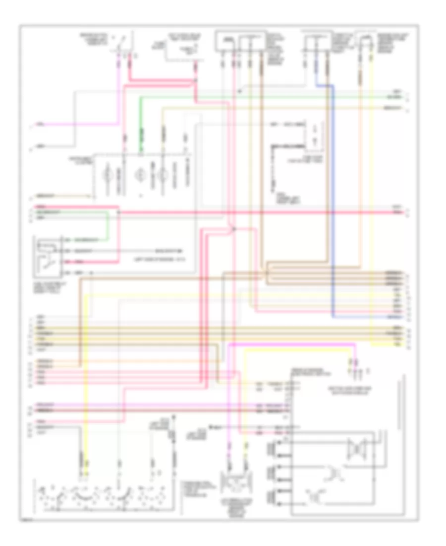
3.1L (VIN M), Engine Performance Wiring Diagrams (2 of 3) for Chevrolet Beretta 1996
List of elements for 3.1L (VIN M), Engine Performance Wiring Diagrams (2 of 3) for Chevrolet Beretta 1996:
- (left side of engine)
- (rear of engine) electronic ignition
- Brake switch (under left side of i/p)
- Check engine
- Coolant temp
- Digital exhaust gas recirc- ulation valve (rear of engine)
- Engine coolant temperature sensor (rear of engine)
- Fuel pump (top of fuel tank)
- Fuel pump relay (right side of safety wall)
- Fuse 9 20a
- Fuse block
- G112
- G112 (left side of engine)
- G300 (under left front seat)
- Hot in run, bulb test or start
- Ignition amplifier and switching module
- Instrument cluster
- Low oil level
- Low resolution 7x crankshaft sensor (front of engine)
- Nca
- Park/neutral position switch (top of transaxle)
- Plugs spark
- Pnk
- Spark plugs
- Tach signal in
- Tan
- Throttle position sensor (throttle body)
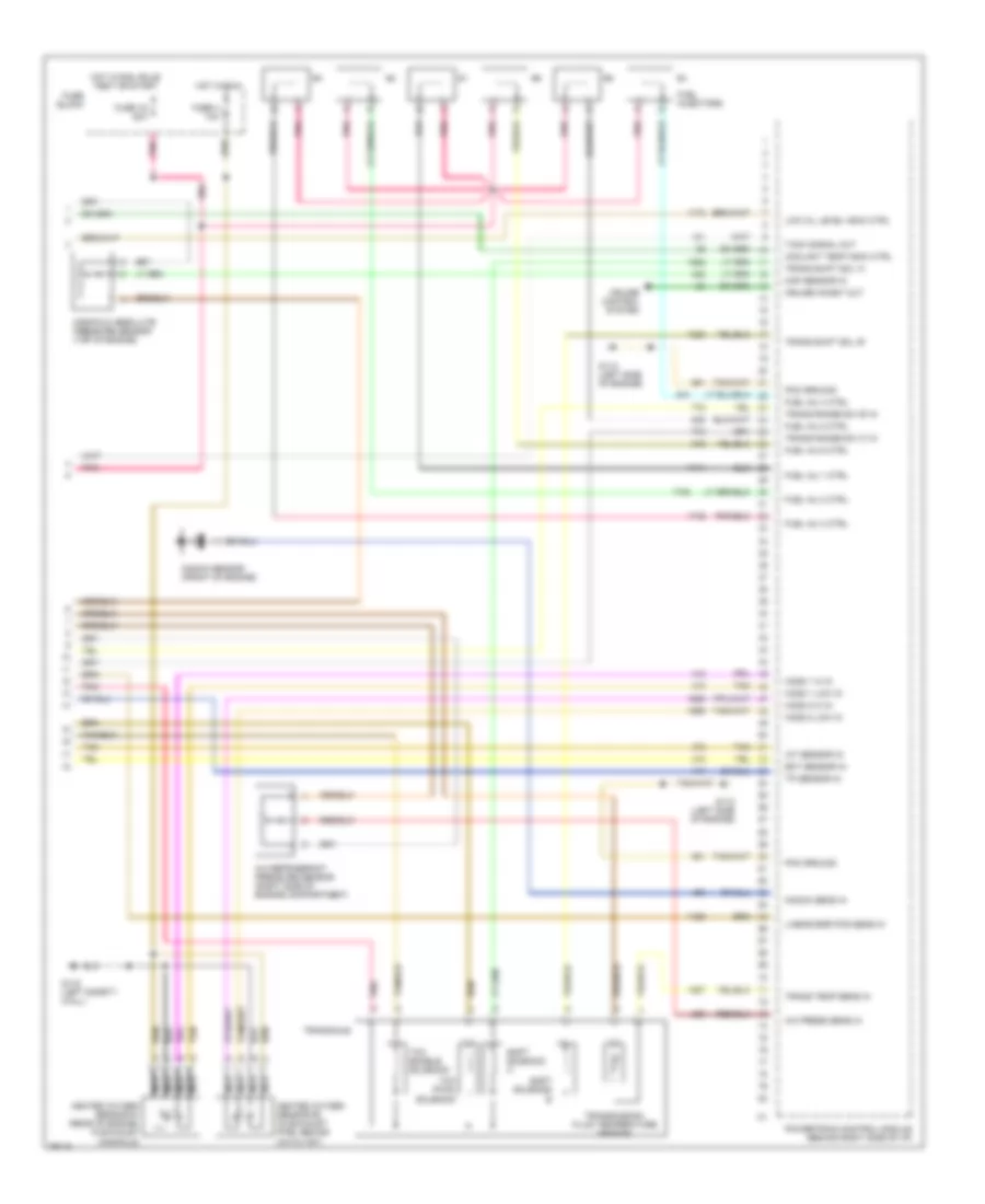
3.1L (VIN M), Engine Performance Wiring Diagrams (3 of 3) for Chevrolet Beretta 1996
List of elements for 3.1L (VIN M), Engine Performance Wiring Diagrams (3 of 3) for Chevrolet Beretta 1996:
- A/c press sens in
- A/c refrigerant pressure sensor (right side of engine compartment)
- Coolant temp indic ctrl
- Cruise control system
- Cruise inhibit out
- Ect sensor in
- Fuel inj 1 ctrl
- Fuel inj 2 ctrl
- Fuel inj 3 ctrl
- Fuel inj 4 ctrl
- Fuel inj 5 ctrl
- Fuel inj 6 ctrl
- Fuel injectors
- Fuse 16 20a
- Fuse 4 10a
- Fuse block
- G112 (left side of engine)
- G116 (left safety wall)
- Heated oxygen sensor #1 (rear of engine, in exhaust manifold)
- Heated oxygen sensor #2 (in exhaust pipe, behind catalyst)
- Ho2s 1 hi in
- Ho2s 1 low in
- Ho2s 2 hi in
- Ho2s 2 low in
- Hot in run
- Hot in run, bulb test or start
- Iat sensor in
- Knock sens in
- Knock sensor (front of engine)
- Linear egr pos sens in
- Low oil level indic ctrl
- Manifold absolute pressure sensor (top of engine)
- Map sensor in
- Nca
- Pcm ground
- Pnk
- Powertrain control module (behind right side of i/p)
- Shift solenoid a
- Shift solenoid b
- Tach signal out
- Tan
- Tcc (pwm) solenoid
- Tcc enable solenoid
- Tp sensor in
- Trans range sw 'b' in
- Trans range sw 'c' in
- Trans shift sol 'a'
- Trans shift sol 'b'
- Trans temp sens in
- Transaxle
- Transmission fluid temperature sensor
EXTERIOR LIGHTS
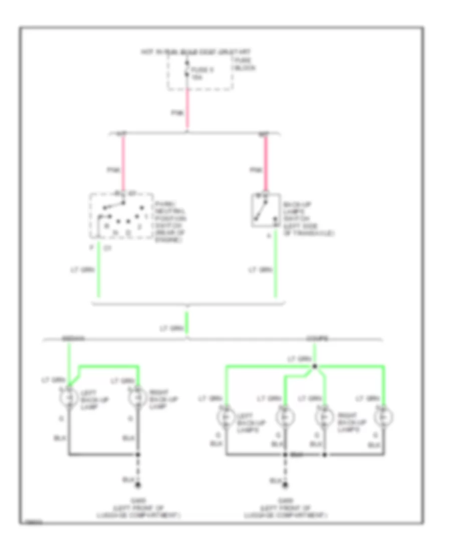
Backup Lamps Wiring Diagram for Chevrolet Beretta 1996
List of elements for Backup Lamps Wiring Diagram for Chevrolet Beretta 1996:
- A/t
- Back-up lamps switch (left side of transaxle)
- Coupe
- Fuse 5 15a
- Fuse block
- G400 (left front of luggage compartment)
- Hot in run, bulb test or start
- Left back-up lamp
- Left back-up lamps
- M/t
- Park/ neutral position switch (rear of engine)
- Pnk
- Right back-up lamp
- Right back-up lamps
- Sedan
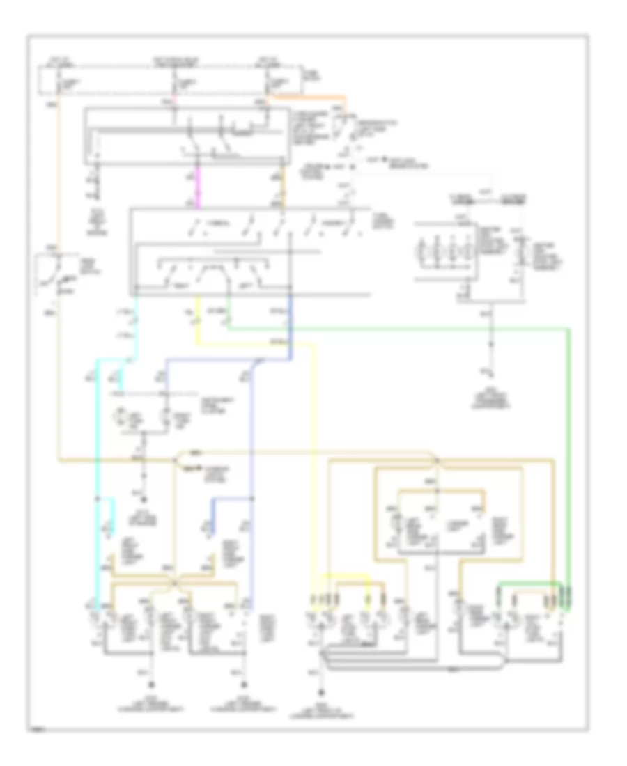
Exterior Lamps Wiring Diagram for Chevrolet Beretta 1996
List of elements for Exterior Lamps Wiring Diagram for Chevrolet Beretta 1996:
- Anti-lock brake system
- Brake switch (left side of i/p)
- Center high mounted stop light assembly
- Cruise control system
- Fuse 2 20a
- Fuse 5 15a
- Fuse 7 20a
- Fuse block
- G100 (left fender, in engine compartment)
- G110 (left front of engine)
- G112 (left side of engine)
- G301 (left front passenger compartment)
- G400 (left front of luggage compartment)
- Hazard
- Head
- Head- lamp switch
- Hot at all times
- Hot in run, bulb test or start
- Instrument panel cluster
- Interior lights system
- Left
- Left front marker light (w/o fog lights)
- Left front park/ turn light
- Left front side marker light
- Left rear marker light
- Left rear side marker light
- Left tail/ stop/ turn lights
- Left turn ind.
- License light
- Logic
- Normal
- Off
- Park
- Pnk
- Right
- Right front marker light (w/o fog lights)
- Right front park/ turn light
- Right front side marker light
- Right rear marker light
- Right rear side marker light
- Right tail/ stop/ turn lights
- Right turn ind.
- Spoiler
- Turn/ hazard- switch
- Turn/hazard flasher (left front of i/p, in convenience center)
- W/ rear
- W/o rear spoiler
GROUND DISTRIBUTION
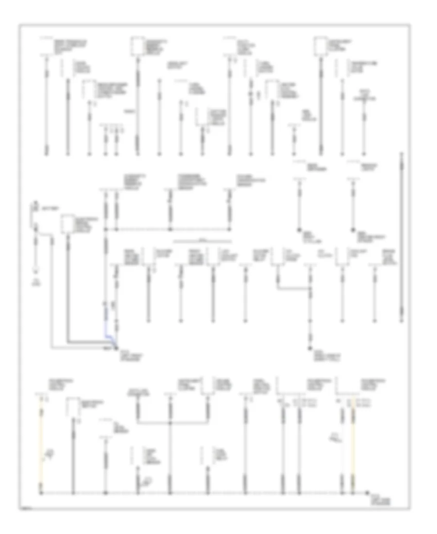
Ground Distribution Wiring Diagram (1 of 2) for Chevrolet Beretta 1996
List of elements for Ground Distribution Wiring Diagram (1 of 2) for Chevrolet Beretta 1996:
- (2.2l) c1
- (2.2l) c2
- (3.1l) c1
- (3.1l) c2
- 2.2l only
- 3.1l
- 3.1l only
- A/c clutch
- A/c clutch diode
- A12
- Abs lamp module
- Battery
- Blower motor
- Blower motor relay
- Brake fluid level switch
- C101
- C205
- Coolant fan
- Cruise control module
- Data link connector
- Daytime running lights module
- Diagnostic energy reserve module
- Door unlock module
- Electronic brake control module
- Electronic ignition
- Foward discriminating sensor
- Front heated oxygen sensor
- Fuel pump relay
- G110 (left front of engine)
- G112 (left side of engine)
- G123 (right side of safety wall)
- G905 (right "c" pillar)
- G908 (center front of roof)
- Headlight switch
- Heater & a/c control assembly
- Instrument panel cluster
- Low coolant switch
- Mass air flow sensor
- Multi- function alarm module
- Nca
- Oil level sensor
- Park/ neutral position switch
- Passenger compartment discriminating sensor
- Powertrain control module
- Radio
- Reading lights
- Rear defogger
- Rear defogger control and wiper/washer switch
- Rear heated oxygen sensor
- Rear transaxle shift interlock solenoid (a/t)
- Tan
- Temperature valve motor
- To g100
- Turn/ hazard flasher
- Turn/ hazard switch
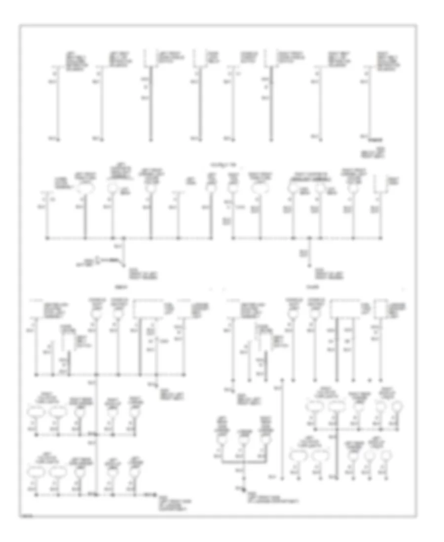
Ground Distribution Wiring Diagram (2 of 2) for Chevrolet Beretta 1996
List of elements for Ground Distribution Wiring Diagram (2 of 2) for Chevrolet Beretta 1996:
- C103
- C300
- Center high mounted stop light assembly
- Cigar lighter
- Console ashtray light
- Console shift light
- Console window switch
- Coupe
- Coupe w/ t96
- Door lock relay
- From a battery
- Fuel tank unit
- G100 (front of left front fender)
- G300 (below left front seat)
- G400 (left front side of luggage compartment)
- High beam
- Left back-up light
- Left back-up lights
- Left composite headlight assembly
- Left fog light
- Left front door handle switch
- Left front marker light (coupe w/o t96)
- Left front park/turn light
- Left horn
- Left license lamp
- Left rear marker light
- Left rear side marker light
- Left seat belt lap retractor solenoid
- Left seat belt shoulder retractor solenoid
- Left tail/stop turn lights
- License lamp
- Low beam
- Luggage compart- ment light
- Nca
- Right back-up light
- Right back-up lights
- Right composite headlight assembly
- Right fog light
- Right front door handle switch
- Right front marker light (coupe w/o t96)
- Right front park/turn light
- Right horn
- Right license lamp
- Right rear marker light
- Right rear side marker light
- Right seat belt lap retractor solenoid
- Right seat belt shoulder retractor solenoid
- Right tail/stop turn lights
- Seat belt switch
- Sedan
- Wiper motor assembly
HEADLIGHTS
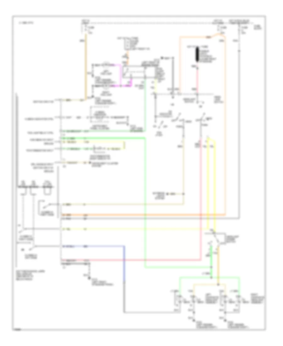
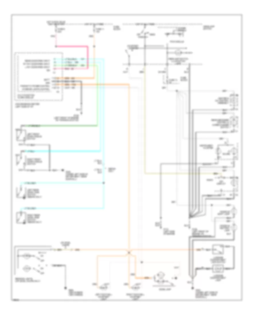
Headlight Wiring Diagram for Chevrolet Beretta 1996
List of elements for Headlight Wiring Diagram for Chevrolet Beretta 1996:
- 1995 vftc c
- Closed in day mode
- Closed in night mode
- Daytime running lamps (drl) module (center of i/p, below radio)
- Drl disable input
- Exterior lights system
- Fog lamp relay (left front i/p)
- Fog lamp relay ctrl
- Fog lp sw
- Fuse 10a
- Fuse 20a
- Fuse block
- G102 (left fender, in engine compt.)
- G110 (left front of engine/trans.)
- G112 (left side of engine)
- Ground
- Hd lps enable
- Head
- Head- lamp switch
- Headlamp dimmer switch
- Headlamp switch
- Hi beam
- Hi beam indicator
- Hi beam indicator ctrl
- High beam on input
- Hot at all times
- Hot in run
- Hot in run, bulb test or start
- Ignition input #1
- Ignition input #3
- Inline fuse 20a (left front i/p)
- Instrument cluster system
- Instrument panel cluster
- Left composite headlamp assembly
- Left fog lamp
- Lo beam
- Low
- Off
- On indicator
- Park
- Photoresistor (right side of i/p)
- Photoresistor input
- Pnk
- Red
- Right composite headlamp assembly
- Right fog lamp
- Tail/ ft lps enable
- Tan
HORN
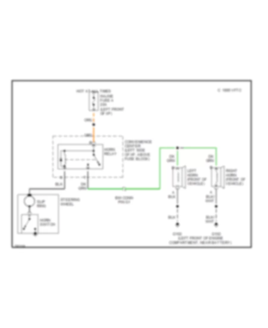
Horn Wiring Diagram for Chevrolet Beretta 1996
List of elements for Horn Wiring Diagram for Chevrolet Beretta 1996:
- (left front of engine
- (left front of i/p)
- 1995 vftc c
- B/h conn pin g1
- Compartment, near battery)
- Convenience center (left side of i/p, above fuse block)
- G102
- Horn relay
- Horn switch
- Hot at all times
- In-line fuse a 20a
- Left horn (front of vehicle)
- Right horn (front of vehicle)
- Slip ring
- Steering wheel
INSTRUMENT CLUSTER
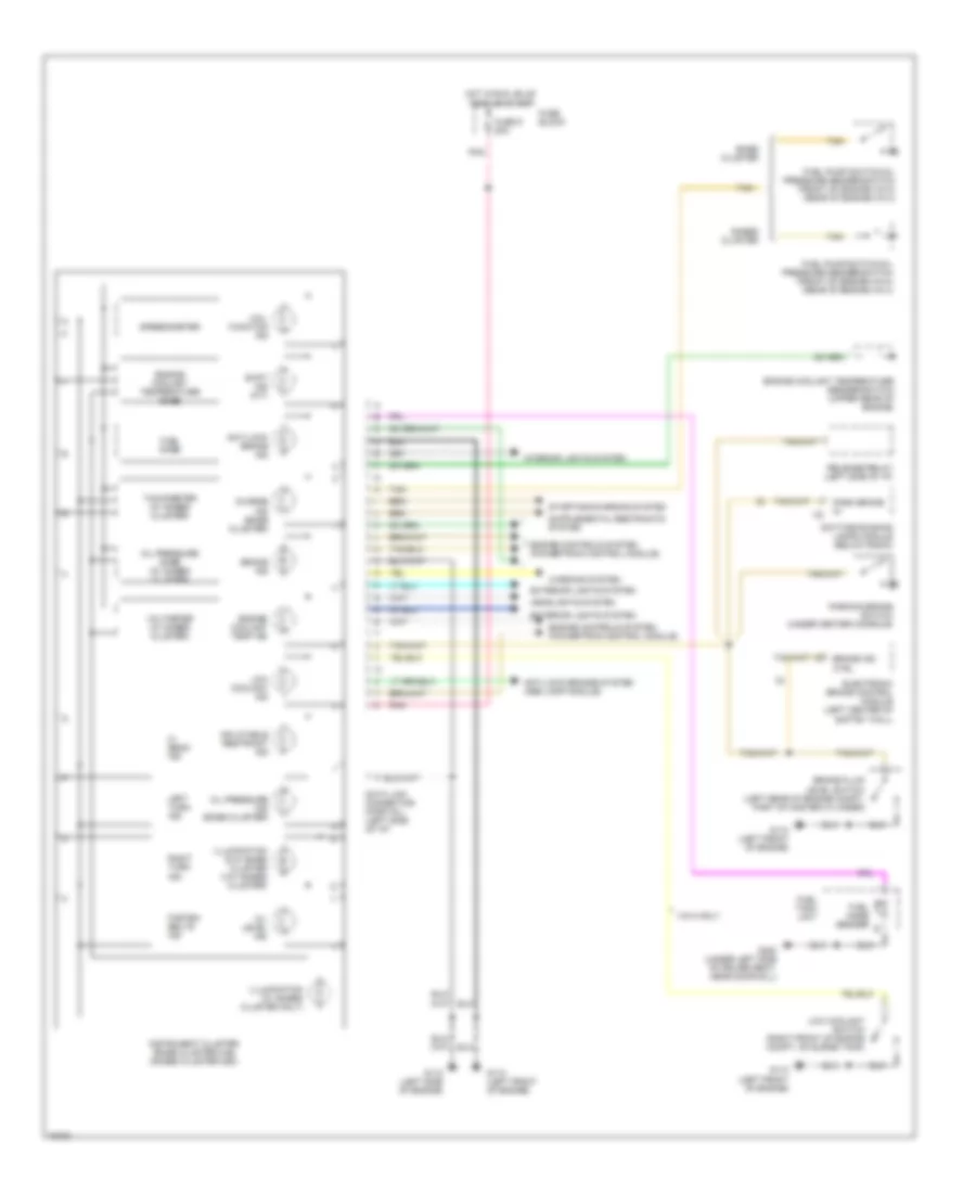
Instrument Cluster Wiring Diagram for Chevrolet Beretta 1996
List of elements for Instrument Cluster Wiring Diagram for Chevrolet Beretta 1996:
- Anti-lock brake ind
- Anti-lock brakes system (abs lamp module)
- Base cluster
- Brake fluid level switch (left rear of engine compt, part of master cylinder)
- Brake ind
- Brake ind ctrl
- Charge ind (base cluster)
- Data link connector (partial) (left side of i/p)
- Daytime running lamps module (below radio)
- Electronic brake control module (left center of saftey wall)
- Engine controls system (powertrain control module)
- Engine coolant temp ind
- Engine coolant temperature gage
- Engine coolant temperature sender/switch (upper rear of engine)
- Exterior lights system
- Fasten belts ind
- Fuel gage
- Fuel gage sender
- Fuel pump switch/oil pressure sender/switch (front of engine-vin m) (rear of engine-vin 4)
- Fuel tank unit
- Fuse 9 20a
- Fuse block
- G110 (left front of engine)
- G112 (left side of engine)
- G300 (under left side of driver seat, near door sill)
- Gages cluster
- Headlights system
- Hi beam ind
- Hot in run, bulb test or start
- Illumination (2-w/ base cluster 3-w/ gages cluster)
- Illumination (w/ gages cluster only)
- Inflatable restraint ind
- Instrument cluster (base cluster-uh6) (gages cluster-ub3)
- Interior lights system
- Left turn ind
- Low coolant ind
- Low coolant switch (right front of engine compt, on surge tank)
- Mal- function ind
- Oil level ind
- Oil pressure gage (w/ gages cluster
- Oil pressure ind (base cluster)
- Park brake in
- Parking brake switch (under center console)
- Pnk
- Release relay (left side of i/p)
- Right turn ind
- Shift ind (m/t)
- Speedometer
- Starting/charging system
- Tachometer (w/ gages cluster)
- Tan
- Vin m only
- Voltmeter (w/ gages cluster)
- Warning system
INTERIOR LIGHTS
Interior Light Wiring Diagram for Chevrolet Beretta 1996
List of elements for Interior Light Wiring Diagram for Chevrolet Beretta 1996:
- (3- bulbs)
- Batt
- Console ashtray lamp
- Console shift lamp
- Convenience center (left side of i/p)
- Courtesy lamps on
- Dim display
- Dimmer switch
- Dome lamp
- Fuse 11 15a
- Fuse 13 3a
- Fuse 9 20a
- Fuse block
- G112 (left side of engine)
- G129 (left front of engine on transaxle stud)
- G129 (left front of engine, on transaxle stud)
- G300 (under left side of driver seat, near door sill)
- G908 (above rear view mirror)
- Gnd
- Head
- Headlamp switch
- Headlamp switch illumination lamp
- Heater & a/c control assembly
- High
- Hot at all times
- Hot in run, bulb test or start
- Ign
- Instrument cluster
- Interior lights control
- L fnt door open input
- Left footwell courtesy light
- Left front door handle switch
- Left rear door jamb switch (sedan only)
- Low
- Luggage compartment lamp
- Luggage compartment lamp switch
- Multi-function alarm module
- Nca
- Off
- Parasitic power control
- Park
- Pnk
- Pwm module
- Radio
- Reading lights (up-level coupe only)
- Rear defogger control & wiper/washer switch
- Rear door open input
- Right footwell courtesy light
- Right front door handle switch
- Right rear door jamb switch (sedan only)
- Rt fnt door open input
- Sedan only
- Up-level coupe
PASSIVE RESTRAINTS
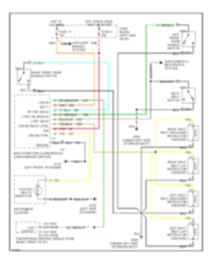
Passive Restraint Wiring Diagram for Chevrolet Beretta 1996
List of elements for Passive Restraint Wiring Diagram for Chevrolet Beretta 1996:
- (l4 vin4) (v6 vin m)
- Anti-lock brakes system
- Batt
- C1 c2
- Fasten belts indicator
- Fuse 11 15a
- Fuse 9 20a
- Fuse block (left side of i/p)
- G110 (left front of engine)
- G112 (left side of engine)
- G300 (under left side of driver seat)
- Ground
- Hot at all times
- Hot in run, bulb test or start
- Ign
- Instrument cluster
- L fnt dr open in
- L fnt s/b in
- Left front door handle switch
- Left seat belt lap retractor solenoid
- Left seat belt shoulder retractor solenoid
- Multi-function alarm module (convenience center)
- Nca
- Pnk
- Powertrain control module (pcm) (right front of i/p)
- Right front door handle switch
- Right seat belt lap retractor solenoid
- Right seat belt shoulder retractor solenoid
- Rt fnt s/b in
- S/b ind ctrl
- S/b retract ctrl
- Seat belt switch
- Vss in
- Vss output
POWER DISTRIBUTION
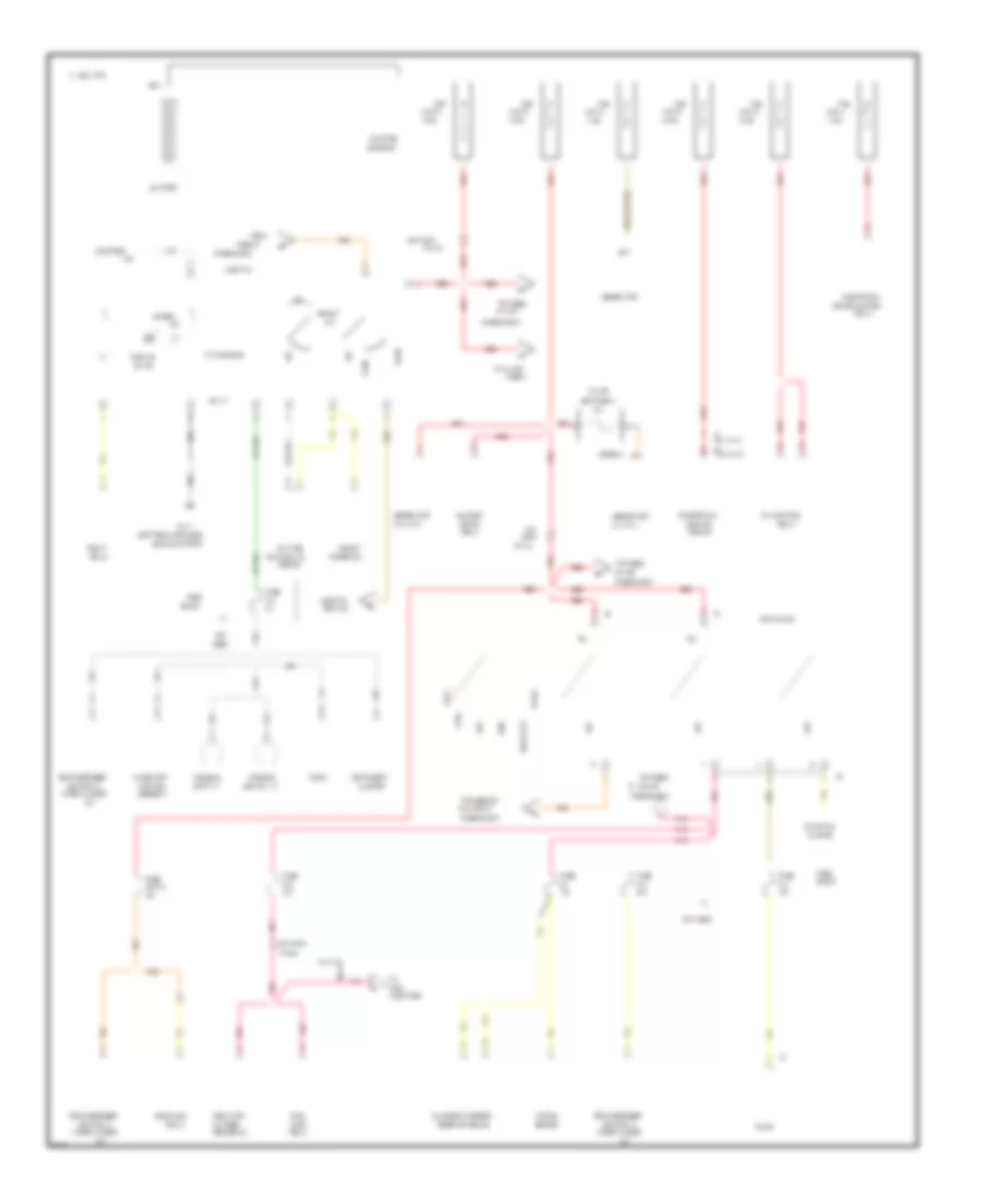
Power Distribution Wiring Diagram (1 of 3) for Chevrolet Beretta 1996
List of elements for Power Distribution Wiring Diagram (1 of 3) for Chevrolet Beretta 1996:
- #1, #5 & #9
- #10
- #13
- #14
- #16
- #2 & #6
- #4 & cb #12
- #7 & #11
- (fuse block)
- (l4 vin 4)
- (l4 vin 4) c2
- (left rear of engine,
- (v6 vin m)
- (v6 vin m) c2
- 10a
- 14 ga
- 15a
- 16 ga
- 1994 vftc c
- 20 ga
- 20a
- 25a
- 30a
- A/c/heater
- A10
- Above starter)
- Accy
- Arming
- Ashtray lt
- Assembly
- B/h
- B/h conn
- Bat
- Battery
- Block
- Blower
- Brake control
- Bulb test
- Cb #15
- Cluster
- Conn
- Console
- Control
- Control &
- Courtesy
- Daytime
- Details
- Diagnostic energy
- Dimmer
- Dimmer sw
- Door lock
- Electronic
- Fan control
- Fog lt
- Fog lts
- From
- Fuel
- Fuel pump/
- Fus
- Fuse
- Fuse #7
- Fuse a
- G114
- Gen fuse a
- Generator
- Head
- Headlt
- Ignition sw
- In/line
- Injectors
- Instrument
- Light sw
- Lighting
- Link a
- Link b
- Link c
- Link d
- Link e
- Link g
- Lock
- Lts
- Module
- Motor
- Not
- Not used
- Off
- Oil pres
- On ind
- Park
- Pin a4
- Pin a5
- Pin b4
- Pnk
- Powertrain
- Pump
- Pwm module
- Radio
- Rear defogger
- Red
- Relay
- Reserve module
- Run
- Running lts
- Sender sw
- Sensor
- Shift lt
- Solenoid
- Start
- Starter
- Starting
- Sw lt
- System
- To fuses
- To fuses #8,
- To in line
- Used
- V6 vin m
- Wiper/washer
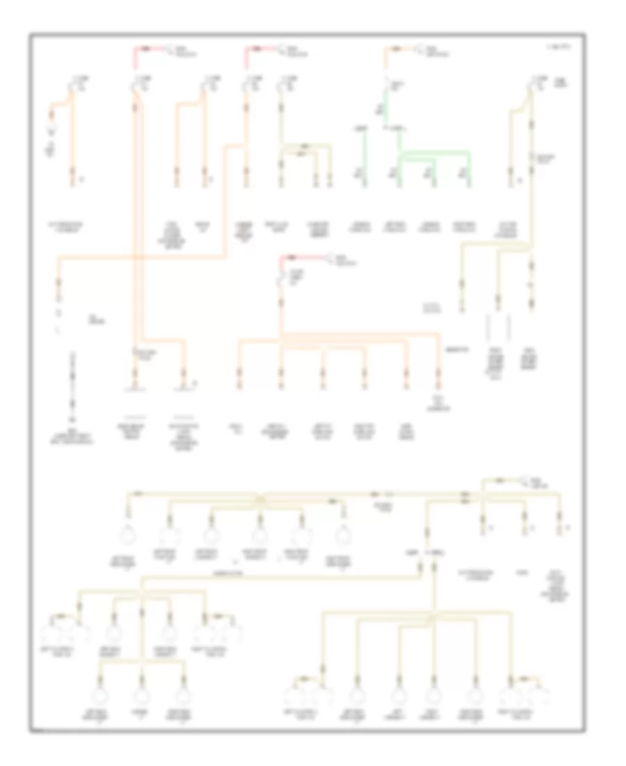
Power Distribution Wiring Diagram (2 of 3) for Chevrolet Beretta 1996
List of elements for Power Distribution Wiring Diagram (2 of 3) for Chevrolet Beretta 1996:
- #11
- (convenience
- (l4 vin 4)
- (under left front
- (v6 vin m
- (v6 vin m)
- 10a
- 15a
- 1994 vftc c
- 2 door
- 20a
- 25a
- 30a
- 4 door
- A/c/heater
- Alarm
- Assembly
- B/h conn
- Block
- Brake
- Cb #12
- Center)
- Cig
- Compt
- Connector
- Console
- Control
- Coupe
- Coupe w/o t96
- Data
- Daytime
- Daytime running
- Door
- Door lock
- Elect brake
- Flasher
- Fog lt
- From
- Front
- Function
- Fus link b
- Fus link d
- Fuse
- Fuse a
- G300
- Generator
- Hazard
- Heated
- Horn rly
- Ignition sw
- In-line
- Left
- Left fnt
- Left front
- Left rear
- Left tail/stop &
- License
- License lt
- Light
- Light sw
- Lighter
- Link
- Lts module
- Luggage
- Marker lt
- Module
- Motor
- Multi-
- Multi-function
- Only)
- Oxygen
- Park/turn
- Pin b1
- Pin c4
- Pin g4
- Radio
- Rear
- Red
- Release
- Right
- Right fnt
- Right front
- Right rear
- Right tail/stop &
- Rly
- Running
- Seat, near door sill)
- Sedan
- Sensor
- Side marker
- Switch
- Temp valve
- Turn lts
- Turn/
- Unlock
- Window sw
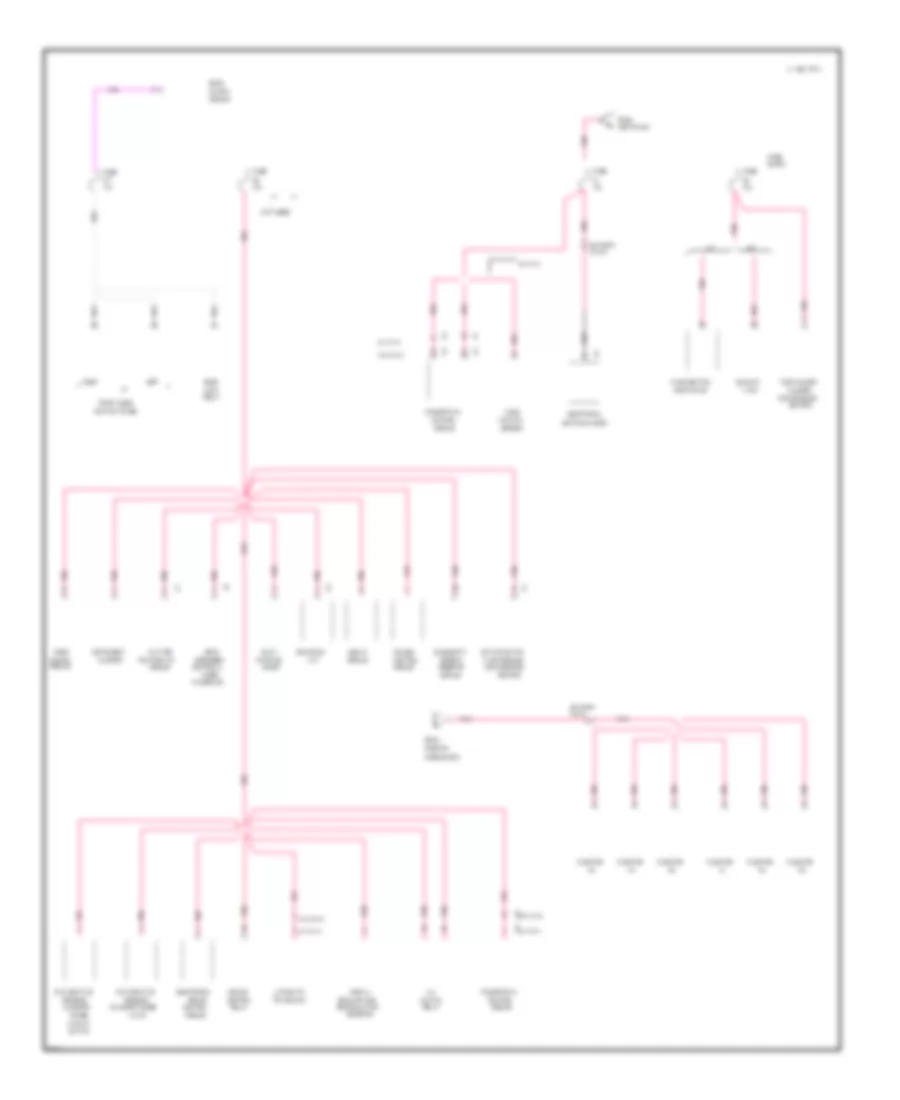
Power Distribution Wiring Diagram (3 of 3) for Chevrolet Beretta 1996
List of elements for Power Distribution Wiring Diagram (3 of 3) for Chevrolet Beretta 1996:
- #17
- (a/t)
- (convenience
- (fuse block)
- (l4 vin 4)
- (l4 vin 4) c3
- (not used)
- (v6 vin m)
- (v6 vin m) c2
- 10a
- 15a
- 1994 vftc c
- 20a
- A/c
- A/t
- Abs lp
- Air flow
- Alarm module
- Automatic
- B/h conn
- Back-up
- Block
- Brake
- Brake sw
- Canister
- Canister purge
- Center)
- Cluster
- Clutch
- Control
- Control &
- Cruise
- Daytime
- Defogger
- Diagnostic
- Digital
- Door
- Electronic
- Emission
- Energy
- Evaporative
- Exhaust gas
- Flasher
- From
- Front door
- Function
- Fuse
- Fuse #16
- Ignition sw
- Ignition system
- Injector
- Instrument
- Left
- Lever
- Lock
- Lock switches
- Lt sw
- M/t
- Mass
- Module
- Multi-
- Multi-function
- Park/neutral
- Pin d
- Pin f4
- Pnk
- Position sw
- Powertrain
- Purge
- Rear
- Recirculation
- Relay
- Reserve
- Right
- Running lts
- Sensor
- Solenoid
- Switch
- Transaxle
- Turn/hazard
- Unlock
- V6 vin m
- Vacuum
- Valve
- Washer sw
- Wiper/
POWER DOOR LOCKS
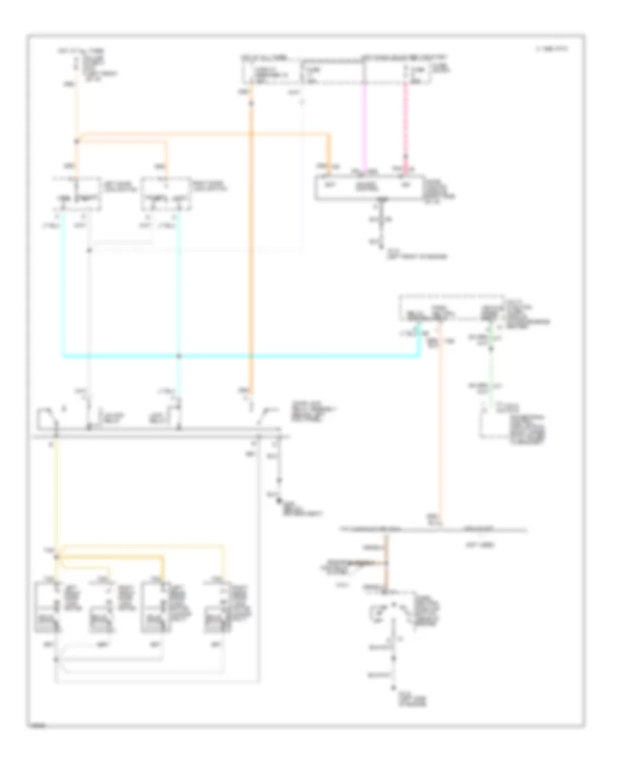
Power Door Lock Wiring Diagram for Chevrolet Beretta 1996
List of elements for Power Door Lock Wiring Diagram for Chevrolet Beretta 1996:
- (behind left kick panel)
- (not used)
- (vin 4) (vin m)
- 1995 vftc c
- Bat
- C1 c2
- Circuit breaker 15 30a
- Controls
- Door lock
- Door unlock module (right side of i/p)
- Engine
- Fuse 10a
- Fuse 20a
- Fuse block
- G110 (left front of engine)
- G112 (left side of engine)
- G300 (below driver's seat)
- Gnd
- Hot at all times
- Hot in run, bulb test or start
- Ign
- In-line fuse a 20a (left front of i/p)
- Left door lock switch
- Left front door lock motor
- Left rear door lock motor (4-door only)
- Lock
- Lock relay
- Multi- function alarm module (in convenience center)
- Park/ neutral input
- Park/ neutral position switch (rear of engine)
- Pnk
- Powertrain control module (pcm) (right upper i/p attached to bracket)
- Relay assembly
- Relay control
- Right front door lock motor
- Right rear door lock motor (4-door only)
- Right door lock switch
- Solid state
- System
- Tan
- Unlock
- Unlock control
- Unlock relay
- Vehicle speed input
- Viin 4 with a/t or vin m
- Vin 4
- Vin 4 w/ m/t
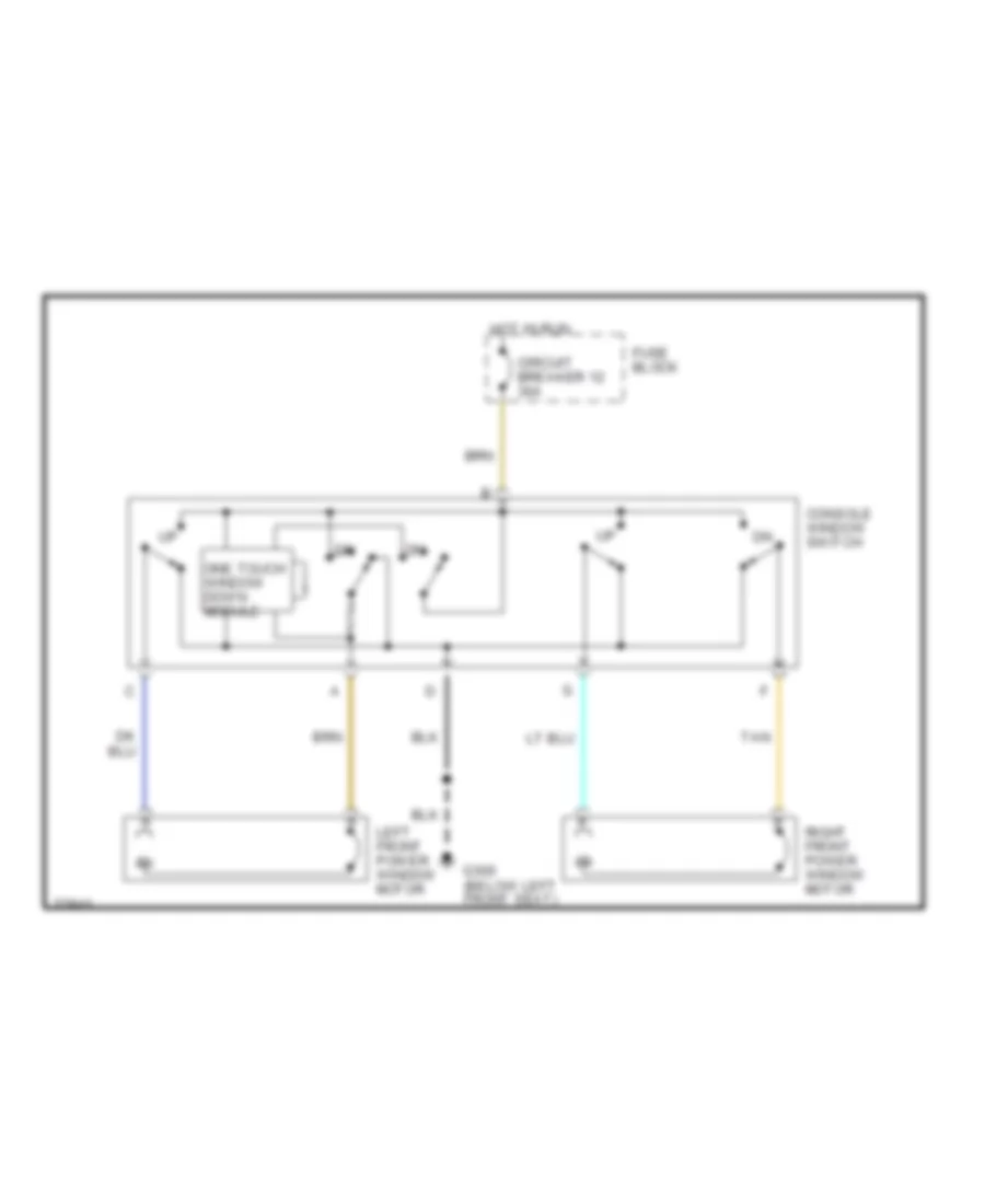
POWER WINDOWS
Power Window Wiring Diagram for Chevrolet Beretta 1996
List of elements for Power Window Wiring Diagram for Chevrolet Beretta 1996:
- Circuit breaker 12 30a
- Console window switch
- Fuse block
- G300 (below left front seat)
- Hot in run
- Left front power window motor
- One touch window down module
- Right front power window motor
- Tan
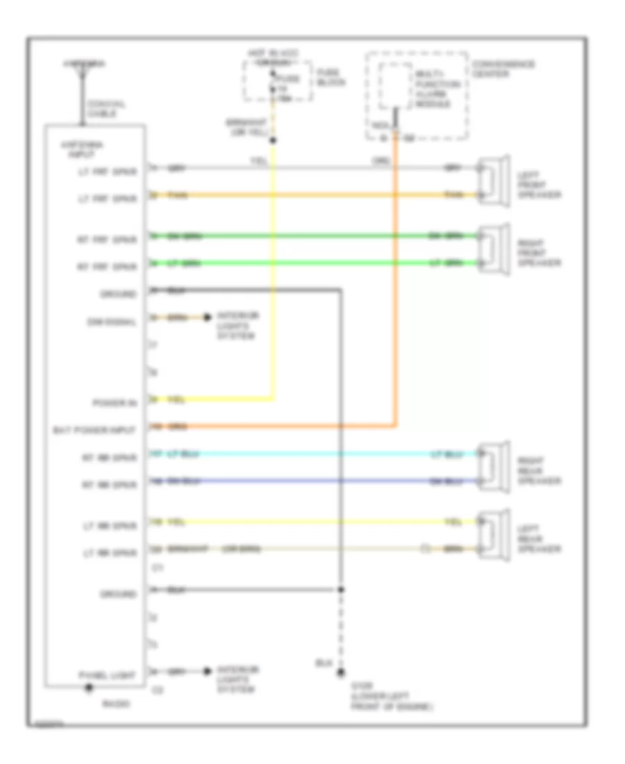
RADIO
Radio Wiring Diagrams for Chevrolet Beretta 1996
List of elements for Radio Wiring Diagrams for Chevrolet Beretta 1996:
- Antenna
- Antenna input
- Bat power input
- Coaxial cable
- Convenience center
- Dim signal
- Fuse 15a
- Fuse block
- G129 (lower left front of engine)
- Ground
- Hot in acc or run
- Interior lights system
- Left front speaker
- Left rear speaker
- Lt frt spkr
- Lt rr spkr
- Multi- function alarm module
- Nca
- Panel light
- Power in
- Radio
- Right front speaker
- Right rear speaker
- Rt frt spkr
- Rt rr spkr
- Tan
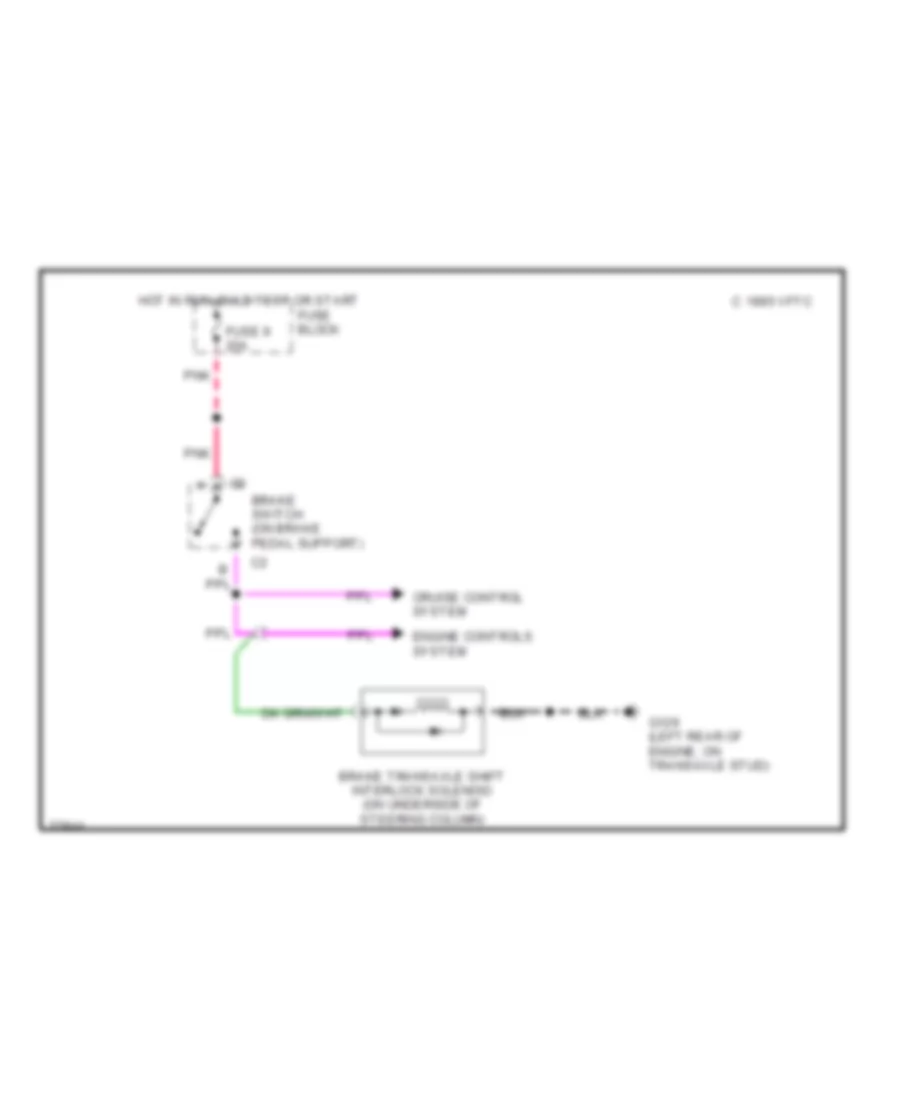
SHIFT INTERLOCKS
Shift Interlock Wiring Diagram for Chevrolet Beretta 1996
List of elements for Shift Interlock Wiring Diagram for Chevrolet Beretta 1996:
- 1995 vftc c
- Brake switch (on brake pedal support)
- Brake transaxle shift interlock solenoid (on underside of steering column)
- Cruise control system
- Engine controls system
- Fuse 9 20a
- Fuse block
- G129 (left rear of engine, on transaxle stud)
- Hot in run, bulb test or start
- Pnk
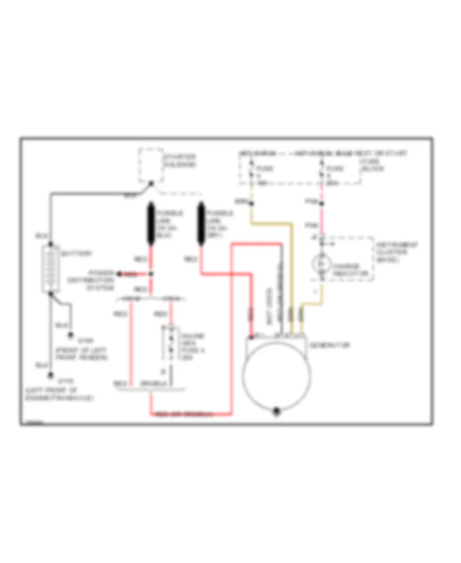
STARTING/CHARGING
Charging Wiring Diagram for Chevrolet Beretta 1996
List of elements for Charging Wiring Diagram for Chevrolet Beretta 1996:
- (front of left front fender)
- (left front of engine/transaxle)
- (not used) p
- Battery
- Charge indicator
- Fuse 10a
- Fuse 20a
- Fuse block
- G100
- G110
- Generator
- Hot in run
- Hot in run, bulb test or start
- In-line gen fuse a 20a
- Instrument cluster (base)
- Pnk
- Power distribution system
- Red
- Starter solenoid
- Vin 4
- Vin m
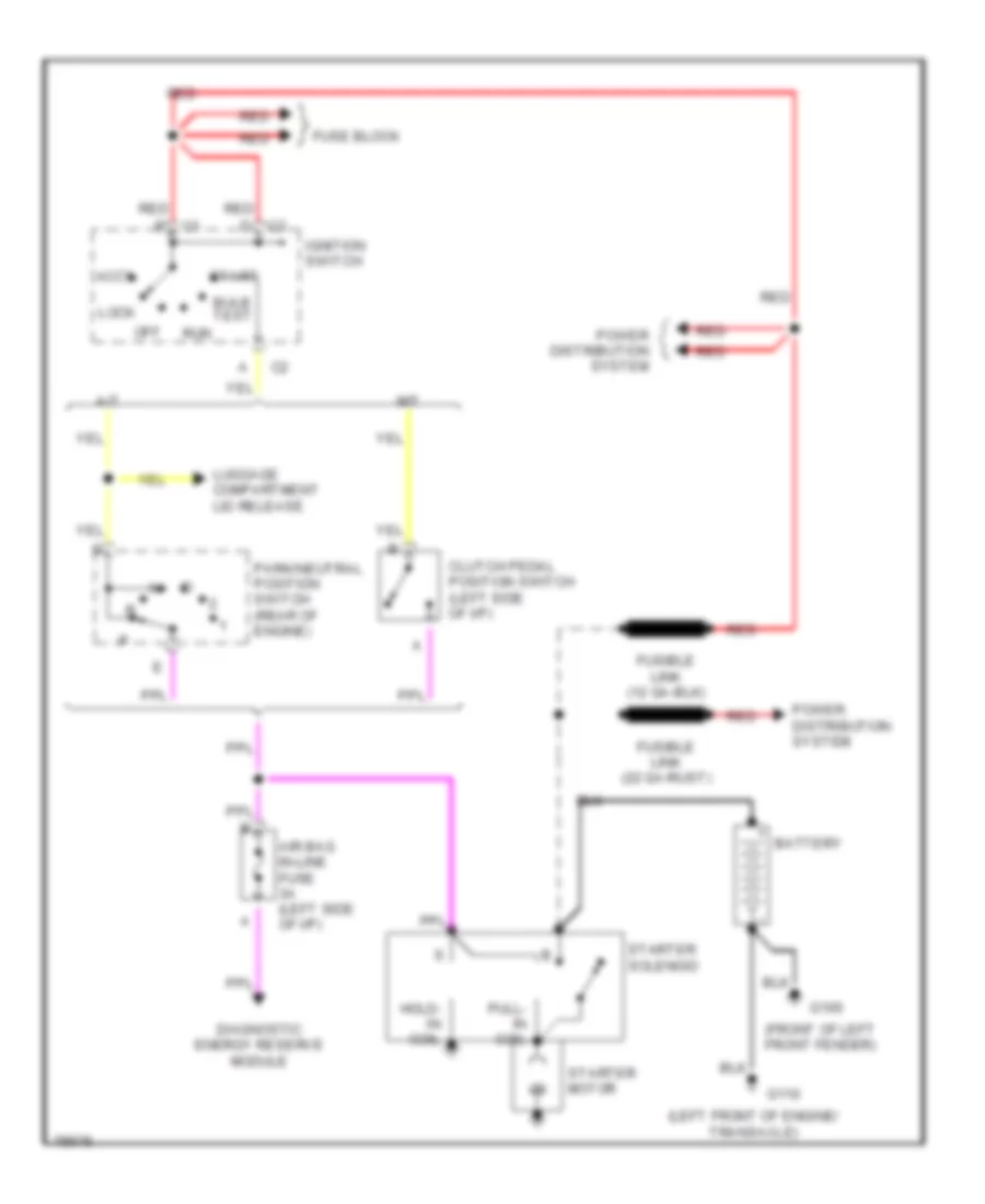
Starting Wiring Diagram for Chevrolet Beretta 1996
List of elements for Starting Wiring Diagram for Chevrolet Beretta 1996:
- (front of left front fender)
- (left front of engine/ transaxle)
- A/t
- Accy
- Air bag in-line fuse 3a (left side of i/p)
- Battery
- Bulb test
- Clutch pedal position switch (left side of i/p)
- Diagnostic energy reserve module
- Fuse block
- Fusible link (22 ga-rust)
- G100
- G110
- Hold- in coil
- Ignition switch
- Lock
- Luggage compartment lid release
- M/t
- Off
- Park/neutral position switch (rear of engine)
- Power distribution system
- Pull- in coil
- Red
- Run
- Start
- Starter motor
- Starter solenoid
SUPPLEMENTAL RESTRAINTS
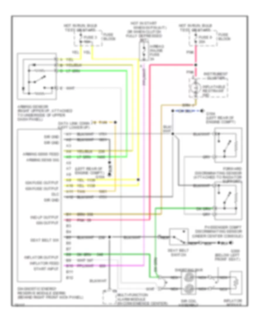
Supplemental Restraint Wiring Diagram for Chevrolet Beretta 1996
List of elements for Supplemental Restraint Wiring Diagram for Chevrolet Beretta 1996:
- (left rear of engine compt)
- A nca
- A10
- A11
- A12
- Airbag in-line fuse 3a
- Arming sens feed
- Arming sens sig
- Arming sensor (right upper i/p, attached to underside of upper dash panel)
- B10
- B11
- B12
- Data link conn (left lower i/p)
- Diagnostic energy reserve module (derm) (behind right front kick panel)
- Dlc
- Forward discriminating sensor (attached to radiator support)
- Fuse 3 10a
- Fuse 9 20a
- Fuse block
- G104
- G104 (left rear of engine compt)
- G300 (below left front seat)
- Hot in run, bulb test or start
- Hot in start
- Ign fuse output
- Ign output
- Ind lp output
- Inflatable restraint ind
- Inflator feed
- Inflator module
- Inflator output
- Instrument cluster
- Multi-function alarm module (in convenience center)
- Nca
- Or when clutch fully depressed (m/t)
- Passenger compt discriminating sensor (under center console)
- Pnk
- Seat belt sw
- Seat belt switch
- Shorting bar
- Sir coil assembly
- Sir gnd
- Start input
- Tan
- When in p/n (a/t)
TRANSMISSION
2.2L
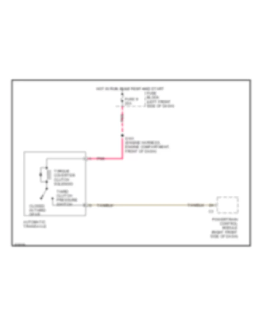
2.2L (VIN 4), Transmission Wiring Diagram for Chevrolet Beretta 1996
List of elements for 2.2L (VIN 4), Transmission Wiring Diagram for Chevrolet Beretta 1996:
- Automatic transaxle
- Closed in third gear
- Fuse 9 20a
- Fuse block (left front side of dash)
- Hot in run, bulb test and start
- Pnk
- Powertrain control module (right front side of dash)
- S101 (engine harness, engine compartment, front of dash)
- Third clutch pressure switch
- Torque coverter clutch solenoid
3.1L
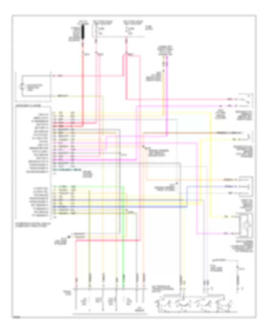
3.1L (VIN M), Transmission Wiring Diagram for Chevrolet Beretta 1996
List of elements for 3.1L (VIN M), Transmission Wiring Diagram for Chevrolet Beretta 1996:
- (engine harness, left rear of engine compt)
- (on transaxle) transaxle range switch
- (under left side of dash) data link connector
- 1-2 ctrl sol
- 1-2 shift sol
- 2-3 ctrl sol
- 2-3 shift sol
- 5v reference
- Battery in
- Brake switch assembly (behind left side of dash)
- Brake switch in
- Cruise control system
- Cruise engaged in
- Data class ii
- Ect sensor in
- Engine coolant temperature sensor (top left side of engine)
- Fuse 15a
- Fuse 20a
- Fuse block
- Fusible link e (22 ga- rust) (starter solenoid)
- G112 (left side of engine)
- Hot at all times
- Hot in run, bulb test or start
- Ignition in
- Instrument cluster
- Malfunction indicator lamp
- Mil indic ctrl
- Pcm ground
- Pnk
- Powertrain control module (under right side of dash)
- Red
- S106
- S107 (engine harness, front of dash)
- S115
- S126
- S179
- S212
- S218 (i/p harn, behind cluster)
- S221 (i/p harn, behind right side of dash)
- S227
- Sensor return
- Serial data
- Tan
- Tcc pwm sol
- Tcc sol
- Tft sensor
- Tft sensor in
- Throttle position sensor (throttle body)
- Tp sensor in
- Trans range "a"
- Trans range "b"
- Trans range "c"
- Trans range "d"
- Trans- axle
- Vehicle speed sensor (lower right rear of engine compt, on transaxle)
- Vss hi in
- Vss lo in
TRUNK, TAILGATE, FUEL DOOR
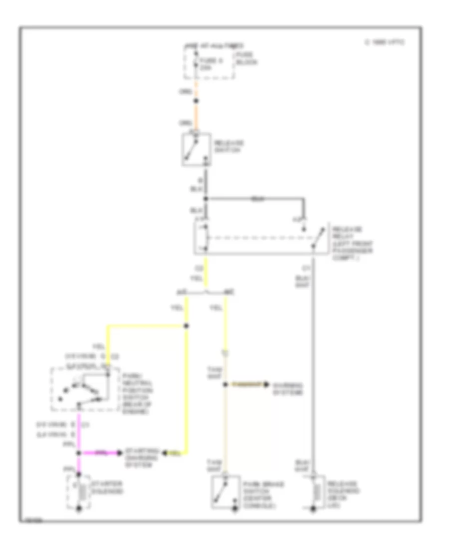
Trunk Release Wiring Diagram for Chevrolet Beretta 1996
List of elements for Trunk Release Wiring Diagram for Chevrolet Beretta 1996:
- (l4 vin h)
- (v6 vin m)
- 1995 vftc c
- A/t
- E c1
- Fuse 6 20a
- Fuse block
- G c2
- Hot at all times
- M/t
- Park brake switch (center console)
- Park/ neutral position switch (rear of engine)
- Release relay (left front passenger compt.)
- Release solenoid (deck lid)
- Release switch
- Starter solenoid
- Starting/ charging system
- Warning systems
WARNING SYSTEMS
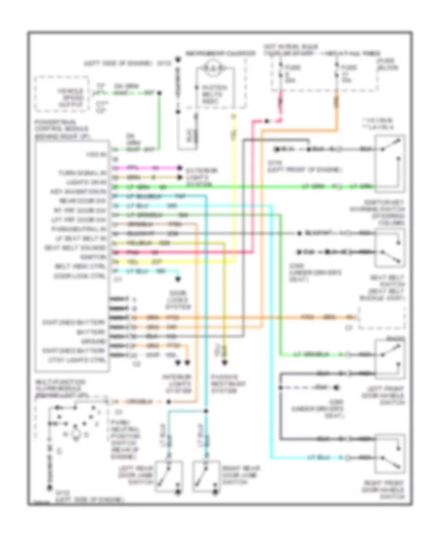
Warning System Wiring Diagrams for Chevrolet Beretta 1996
List of elements for Warning System Wiring Diagrams for Chevrolet Beretta 1996:
- (left side of engine)
- * v6 vin m ** l4 vin 4
- 13* 1**
- Belt indic ctrl
- C1** c2*
- Door lock ctrl
- Door locks system
- Exterior lights system
- Fasten belts indic
- Fuse 15a
- Fuse 20a
- Fuse block
- G110 (left front of engine)
- G112
- G112 (left side of engine)
- G300 (under driver's seat)
- Hot at all times
- Hot in run, bulb test or start
- Ignition
- Ignition key warning switch (steering column)
- Instrument cluster
- Interior lights system
- Key-in-ignition in
- Left front door handle switch
- Left rear door jamb switch
- Lf seat belt in
- Lft frt door sw
- Lights on in
- Multi-function alarm module (behind left i/p)
- Nca
- Nca switched battery nca battery nca ground nca switched battery nca ctsy lights ctrl
- Park/ neutral position switch (rear of engine)
- Park/neutral in
- Passive restraint system
- Pnk
- Powertrain control module (behind right i/p)
- Radio
- Rear door sw
- Right front door handle switch
- Right rear door jamb switch
- Rt frt door sw
- Seat belt solnoid
- Seat belt switch (seat belt buckle assy)
- Turn signal in
- Vehicle speed output
- Vss in
WIPER/WASHER
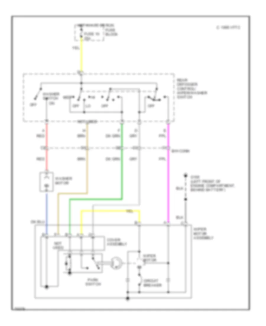
2-Speed Wiper/Washer Wiring Diagram for Chevrolet Beretta 1996
List of elements for 2-Speed Wiper/Washer Wiring Diagram for Chevrolet Beretta 1996:
- 1995 vftc c
- B/h conn
- Circuit breaker
- Cover assembly
- Fuse 10 25a
- Fuse block
- G100 (left front of engine compartment, behind battery)
- Hot in acc or run
- Mist
- Not used
- Off
- Park switch
- Rear defogger control/ wiper/washer switch
- Red
- Washer motor
- Washer switch
- Wiper motor
- Wiper motor assembly
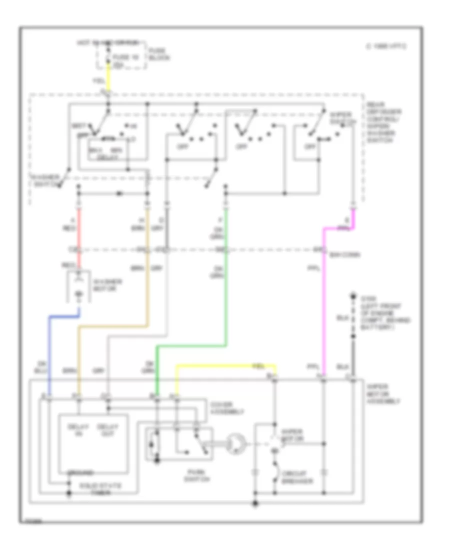
Interval Wiper/Washer Wiring Diagram for Chevrolet Beretta 1996
List of elements for Interval Wiper/Washer Wiring Diagram for Chevrolet Beretta 1996:
- 1995 vftc c
- B/h conn
- Circuit breaker
- Cover assembly
- Delay
- Delay in
- Delay out
- Fuse 10 25a
- Fuse block
- G100 (left front of engine compt, behind battery)
- Ground
- Hot in acc or run
- Max
- Min
- Mist
- Off
- Park switch
- Rear defogger control/ wiper/ washer switch
- Red
- Solid state timer
- Washer motor
- Washer switch
- Wiper motor
- Wiper motor assembly
- Wiper switch