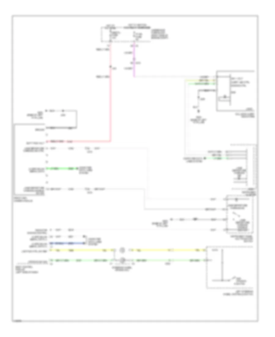
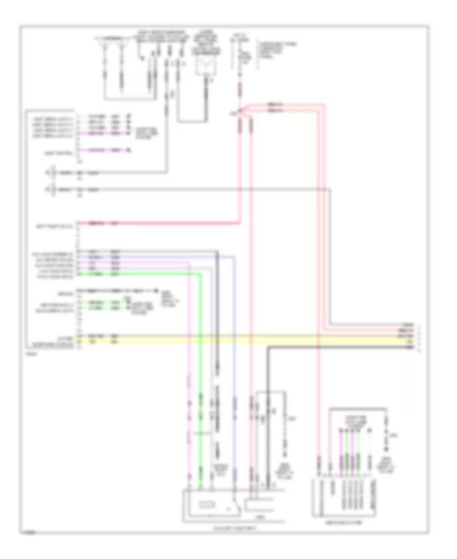
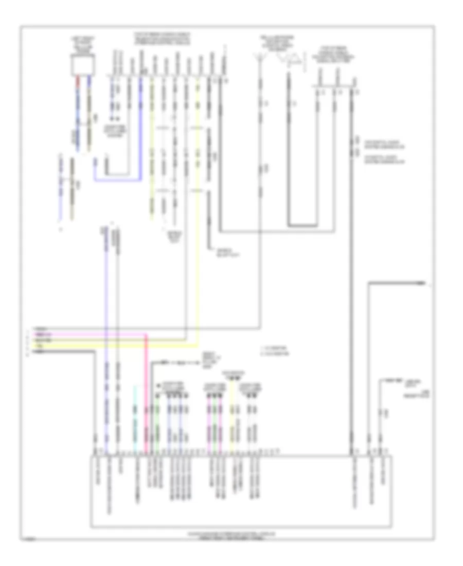
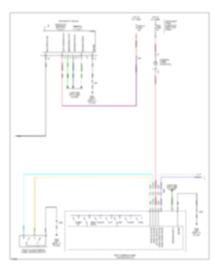
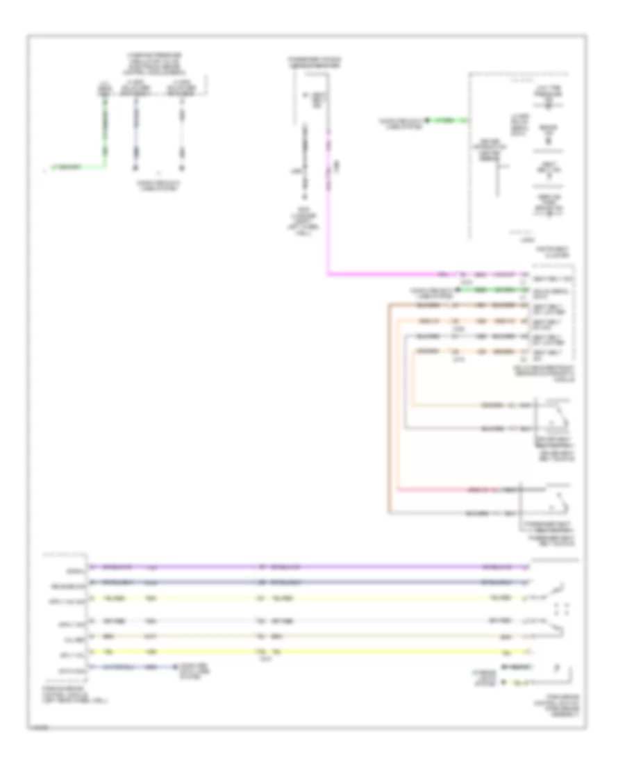
AIR CONDITIONING
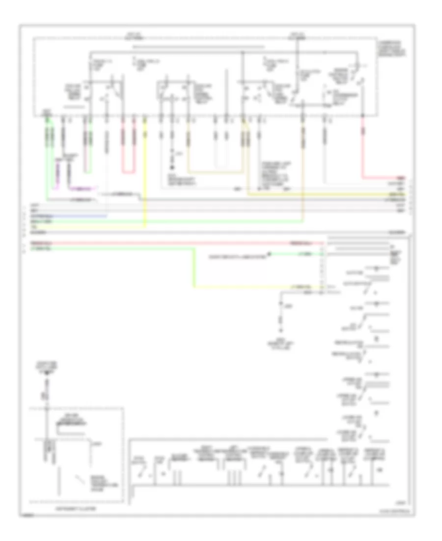
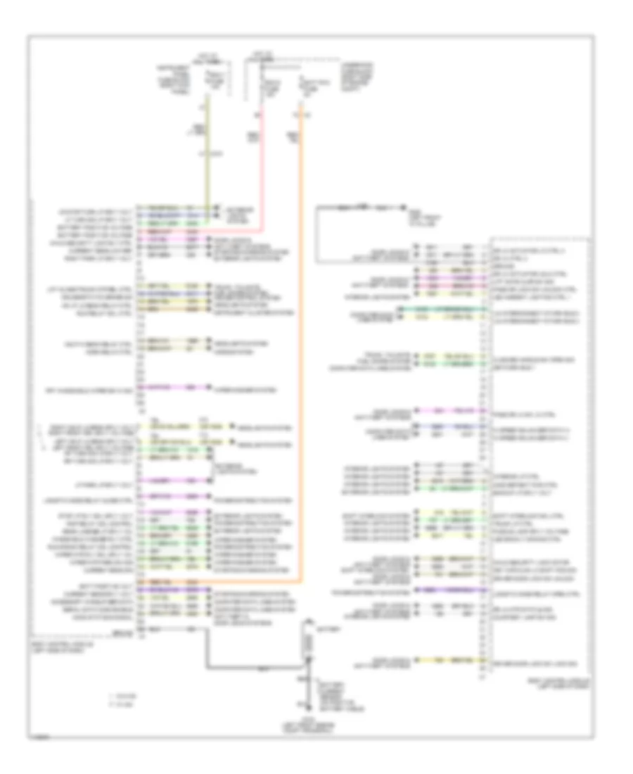
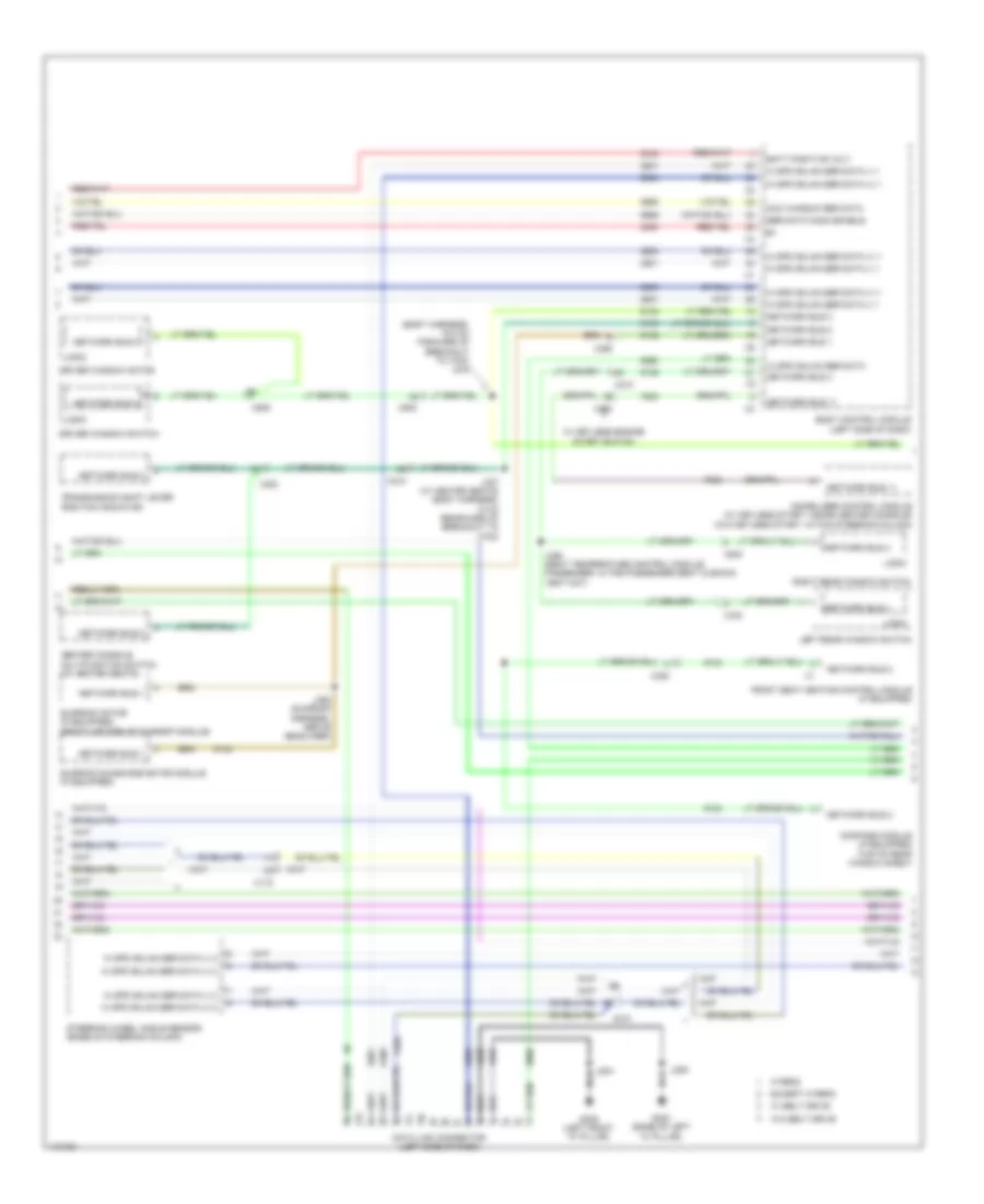
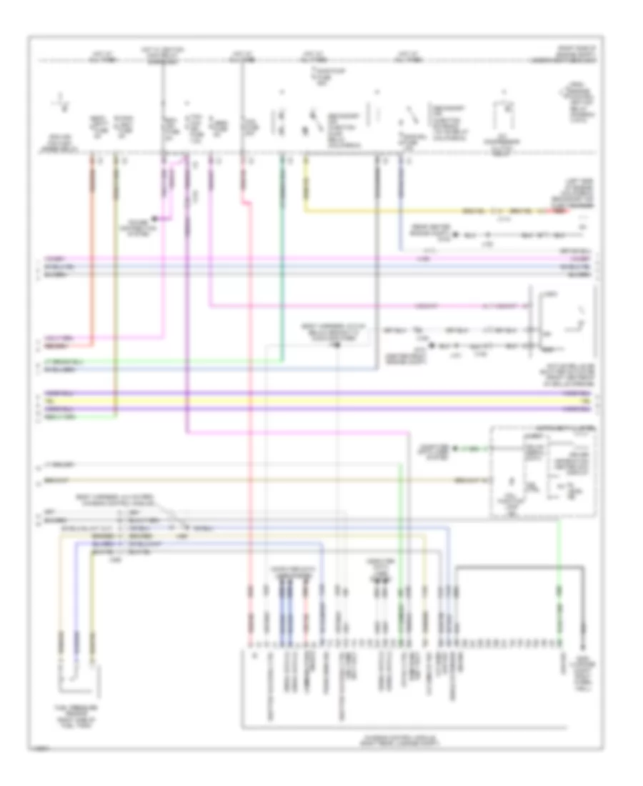
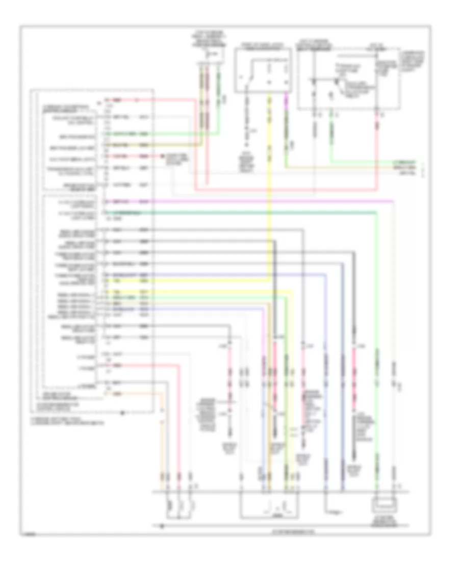
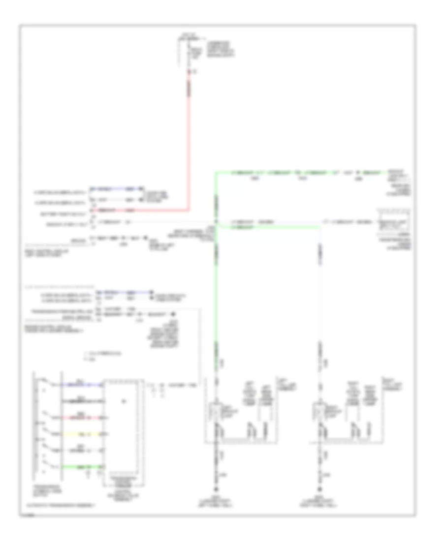
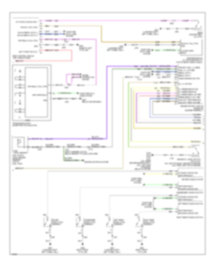
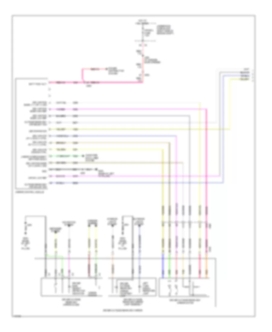
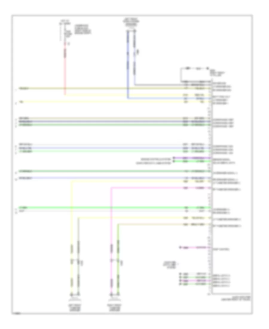
Automatic A/C Wiring Diagram (1 of 4) for Chevrolet Impala LT 2014

List of elements for Automatic A/C Wiring Diagram (1 of 4) for Chevrolet Impala LT 2014:
- (base of left "a' pillar) g203
- 5-volt ref
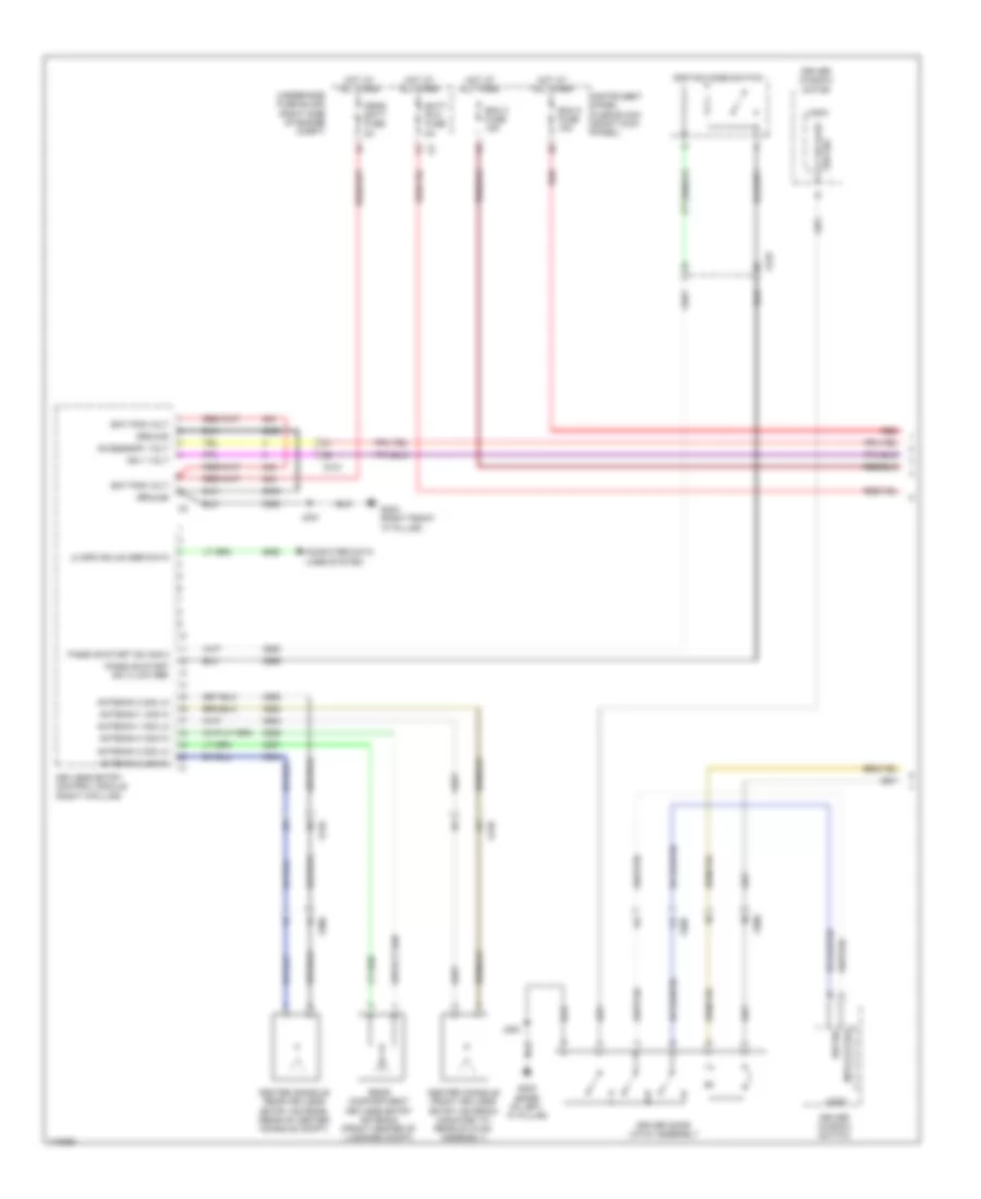
- A/c compressor (lower left front of engine)
- A/c compressor clutch
- A/c compressor solenoid valve
- Battery positive voltage
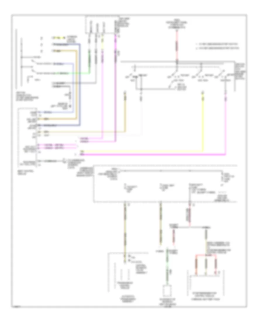
- Blower motor (under right side of dash)
- Blower mtr spd ctrl
- Computer data lines system
- Defogger system
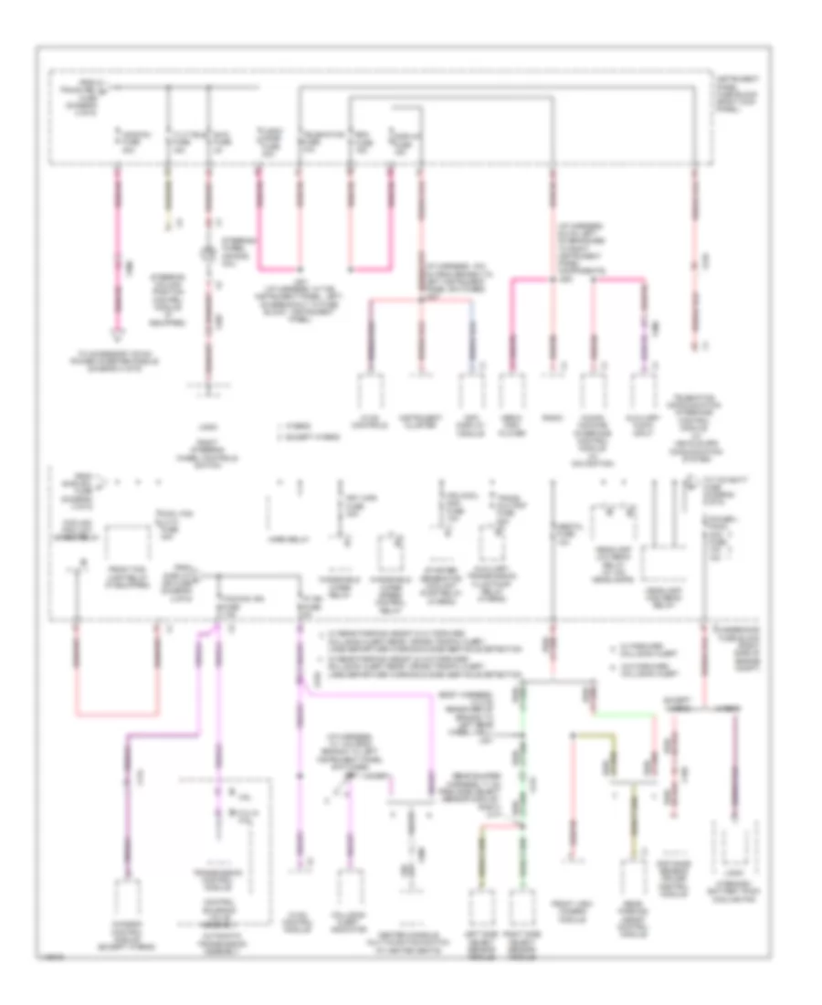
- Display fuse 15a
- Ele variable displacement ctrl
- Ele variable displacement sply
- Frt/hvac fuse 40a
- G120 (3.6l) g122 (except 3.6l) (3.6l: left side of engine, below starter) (except 3.6l: rear center engine compt)
- G302 (right front "a" pillar)
- Gnd
- Ground
- Hot at all times
- Hot w/ ignition main relay energized
- Humidity sens sig
- Humidity temp sens sig
- Hvac control module
- Hvac/cntrl fuse 10a
- Inside air temp sens low ref
- Inside air temp sens sig
- Instrument panel fuse block (right kick panel)
- Ip ign fuse 5a
- J120
- J207
- J209
- J210
- Linear interconnect network bus 9
- Logic
- Low speed gmlan serial data
- Nca
- Power distribution system
- Rear defog rly ctrl
- Red
- Right cooling fan motor (behind right side of radiator)
- Run/crank ignition 1 volt
- Solar sens drv sig
- Spd ctrl blwr mtr
- Temp sens low ref
- Underhood fuse block (right side of engine compt)
- Volt batt pos
- W/ fcw
- W/o fcw
- Windscreen temp sens sig
- Windshield temperature & inside moisture sensor (if equipped)
- X115
- X116
- X200
- X210
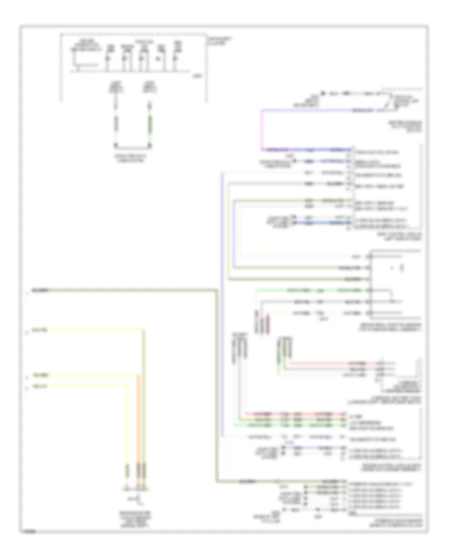
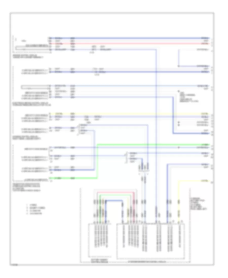
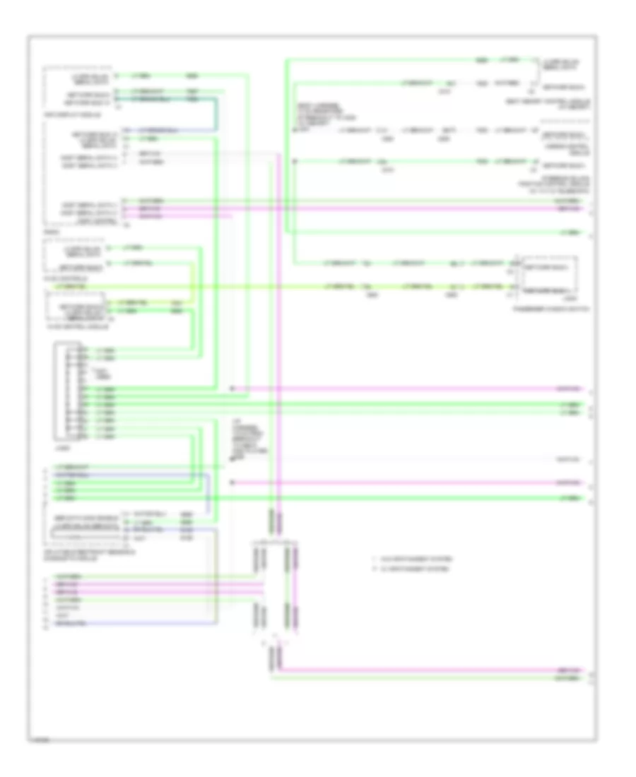
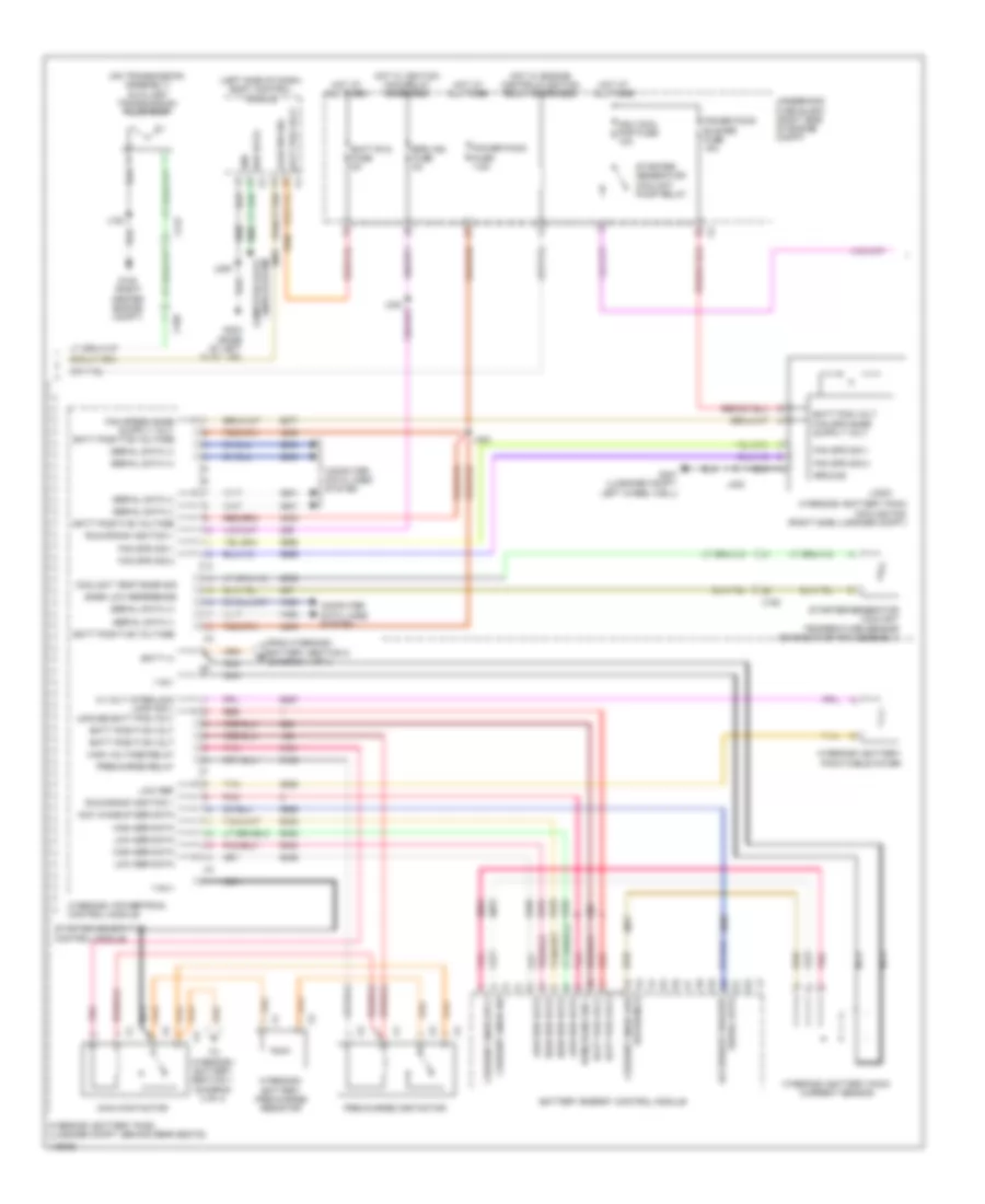
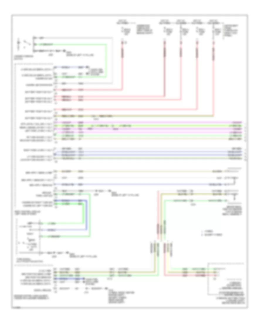
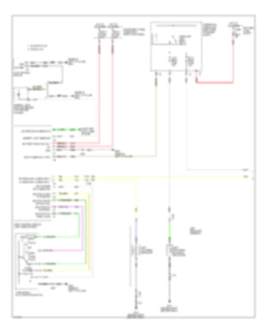
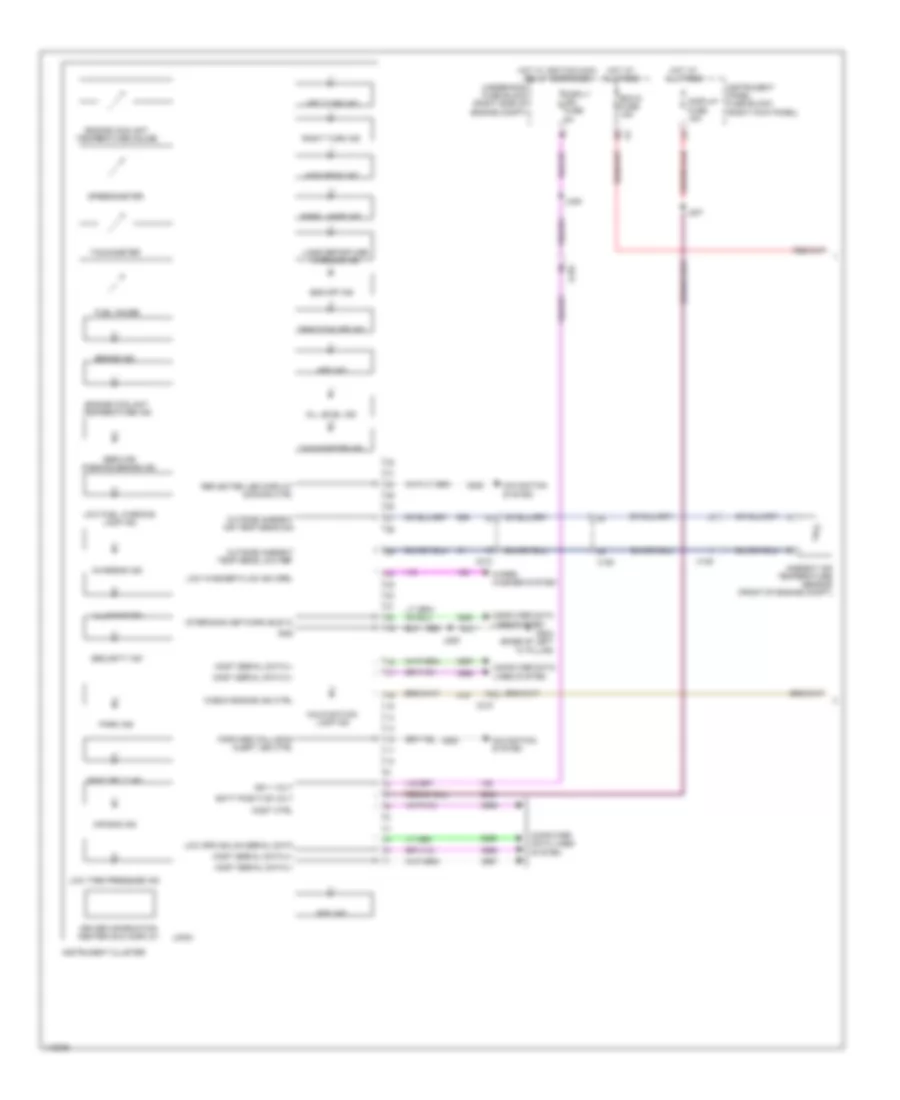
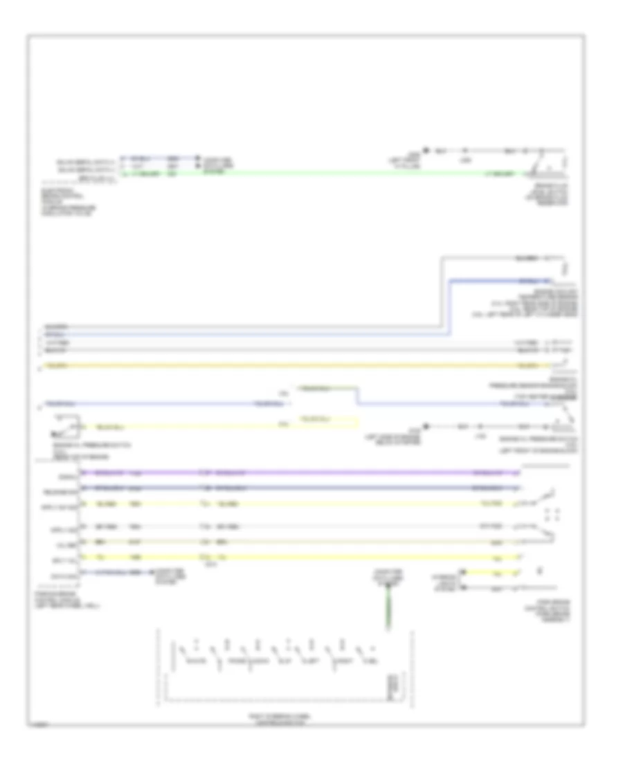
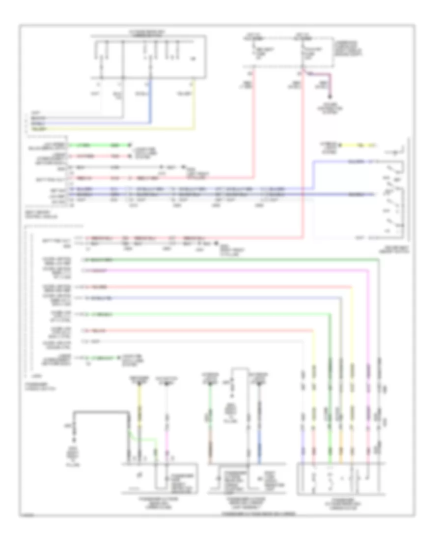
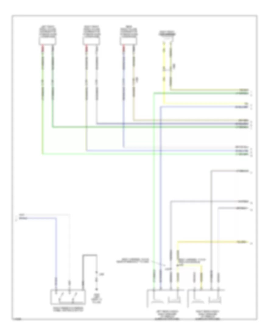
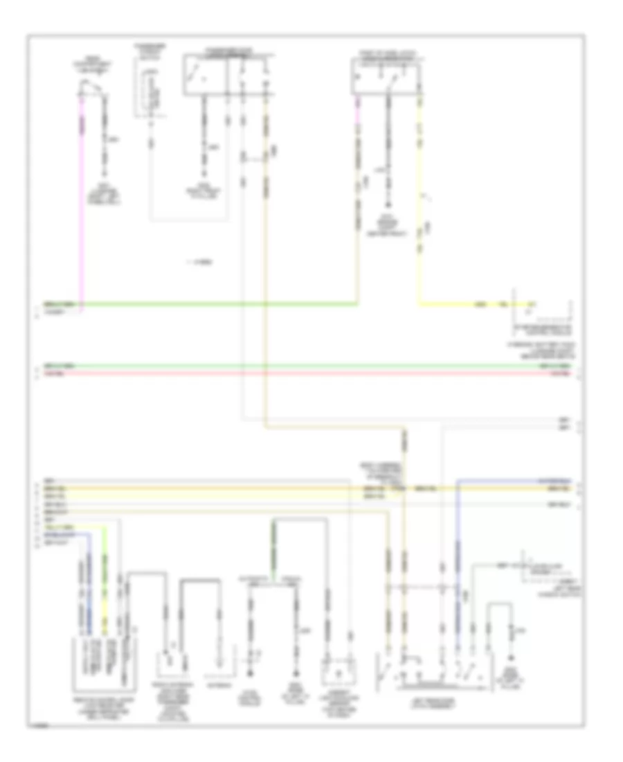
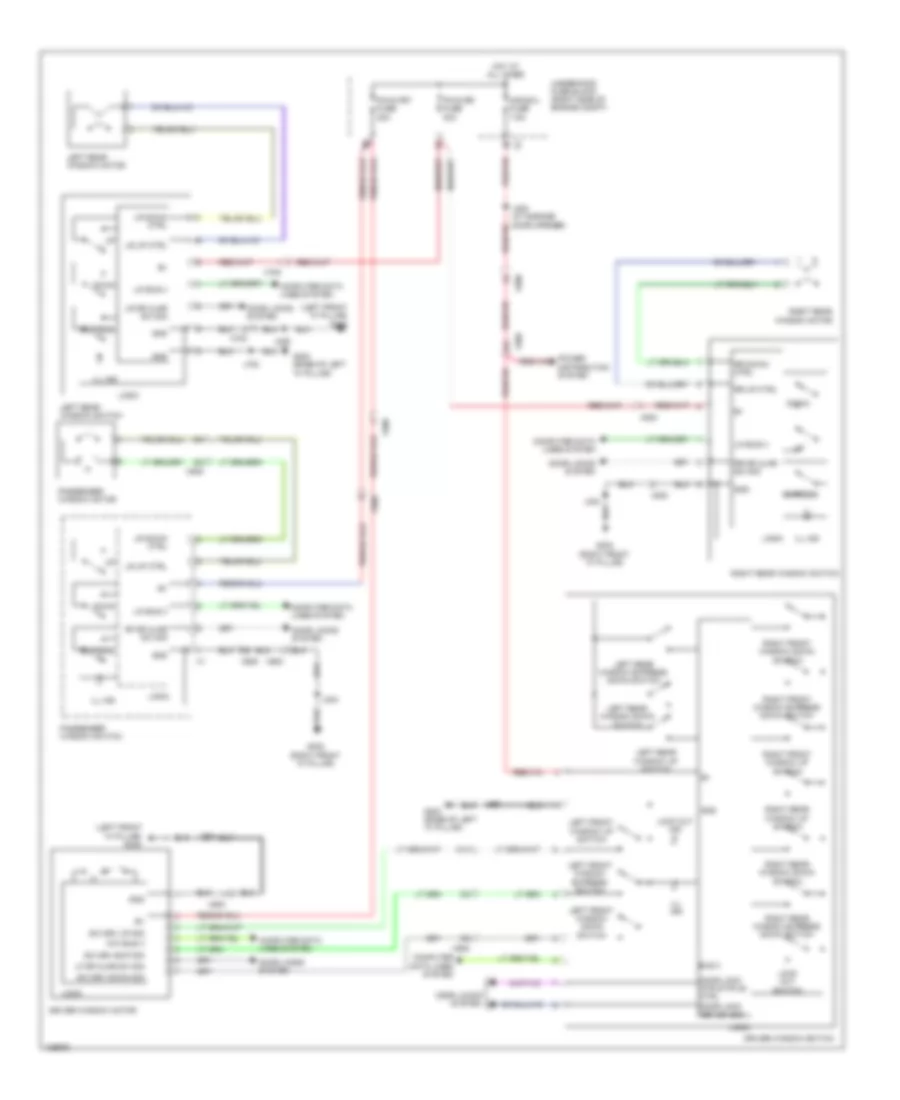
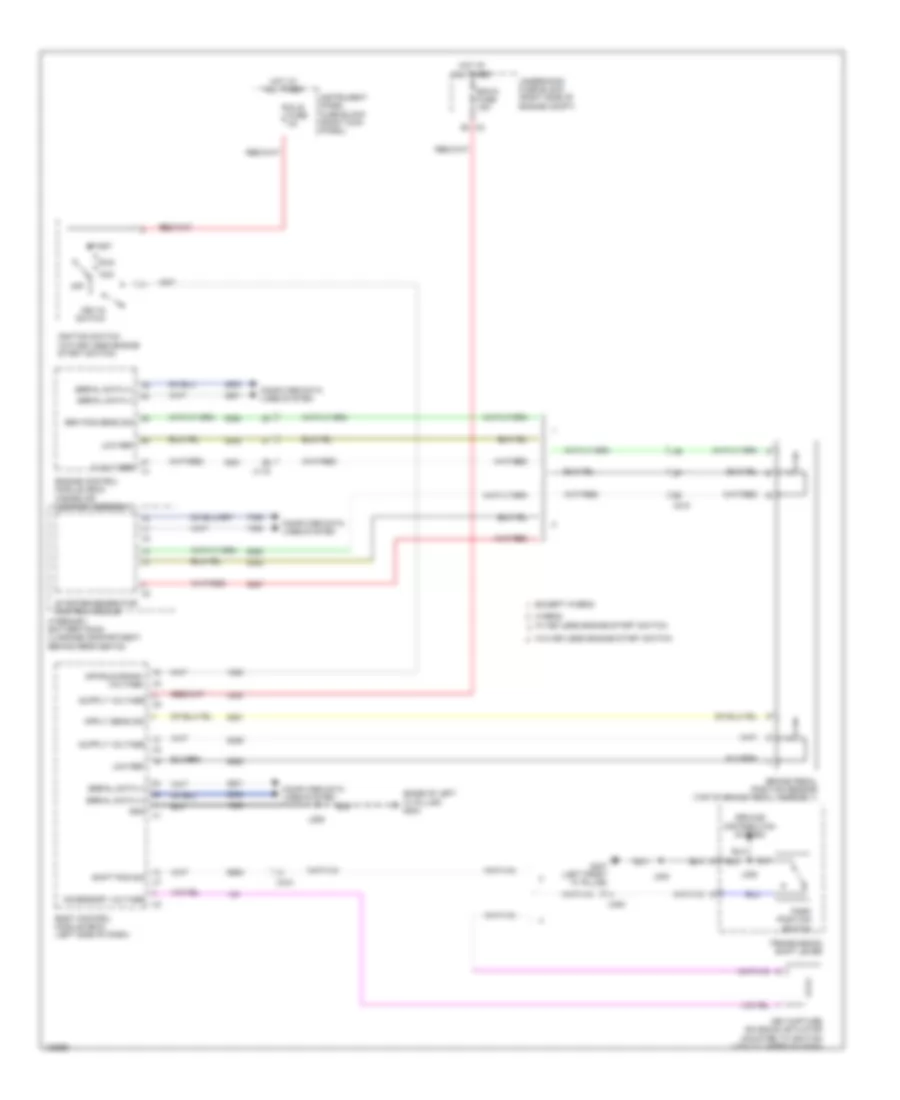
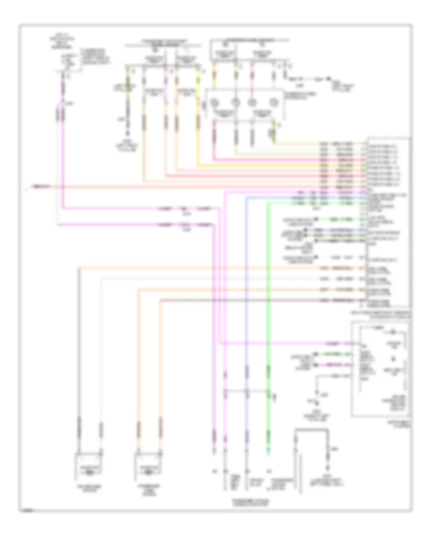
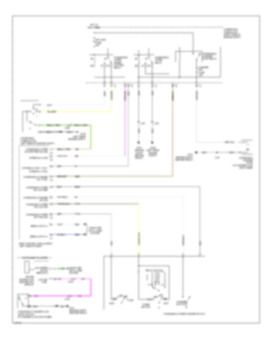
Automatic A/C Wiring Diagram (2 of 4) for Chevrolet Impala LT 2014
List of elements for Automatic A/C Wiring Diagram (2 of 4) for Chevrolet Impala LT 2014:
- (forward lamp harness, 5.8 cm from breakout to washer fluid container) j150
- (not used)
- 2.4l
- 87a
- A/c
- A/c ind
- A/c switch
- Ac clutch fuse 10a
- Auto ind
- Auto switch
- Blower switch
- Bus 9 ser data gnd
- Compressor clutch relay
- Computer data lines system
- Cool fan hi fuse 40a
- Cool fan lo fuse 40a
- Cooling fan high speed relay
- Cooling fan low speed relay
- Cooling fan speed control relay
- Defrost & lower air outlet ind
- Defrost & lower air outlet switch
- Driver information center display
- Engine controls ignition relay
- Engine coolant temperature gauge
- Except 2.4l
- Fan rly a fuse 10a
- G101 (engine compt center front)
- G203 (base of left "a" pillar)
- Hot at all times
- Hvac controls
- Instrument cluster
- J101
- J209
- Left temperature control switch
- Logic
- Lower air outlet ind
- Lower air outlet switch
- Recirculation ind
- Recirculation switch
- Red
- Right temperature control switch
- Serial data gmlan low speed
- Sync ind
- Sync switch
- Underhood fuse block (right side of engine compt)
- Upper & lower air outlet ind
- Upper & lower air outlet switch
- Upper air outlet ind
- Upper air outlet switch
- Windshield defrost ind
- Windshield defrost switch
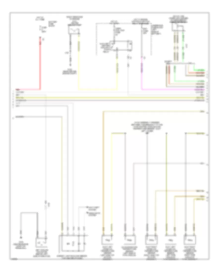
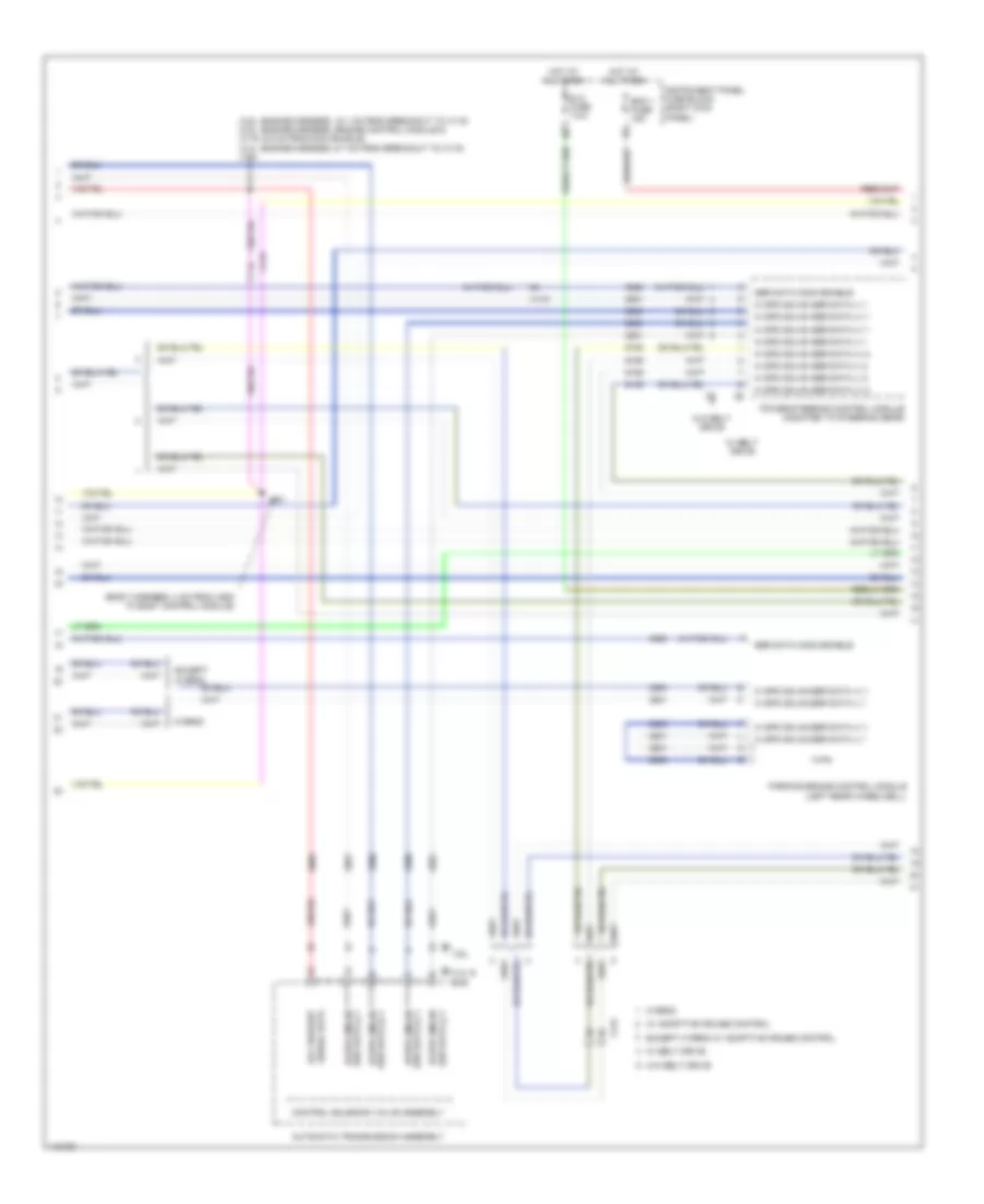
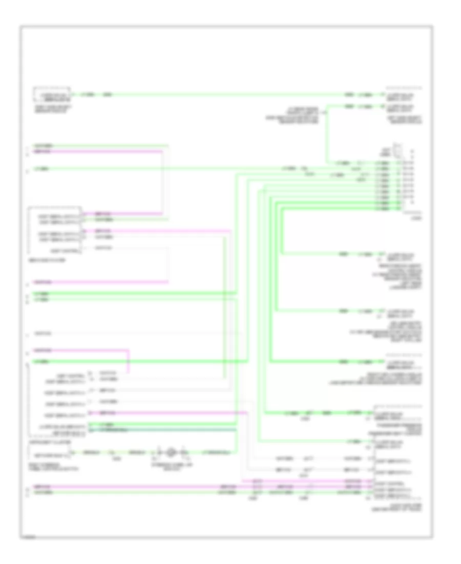
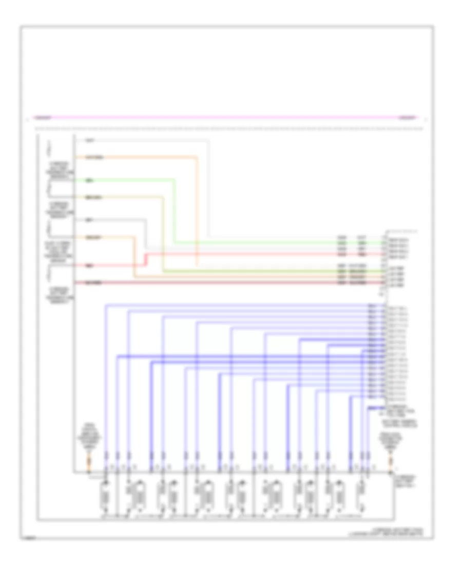
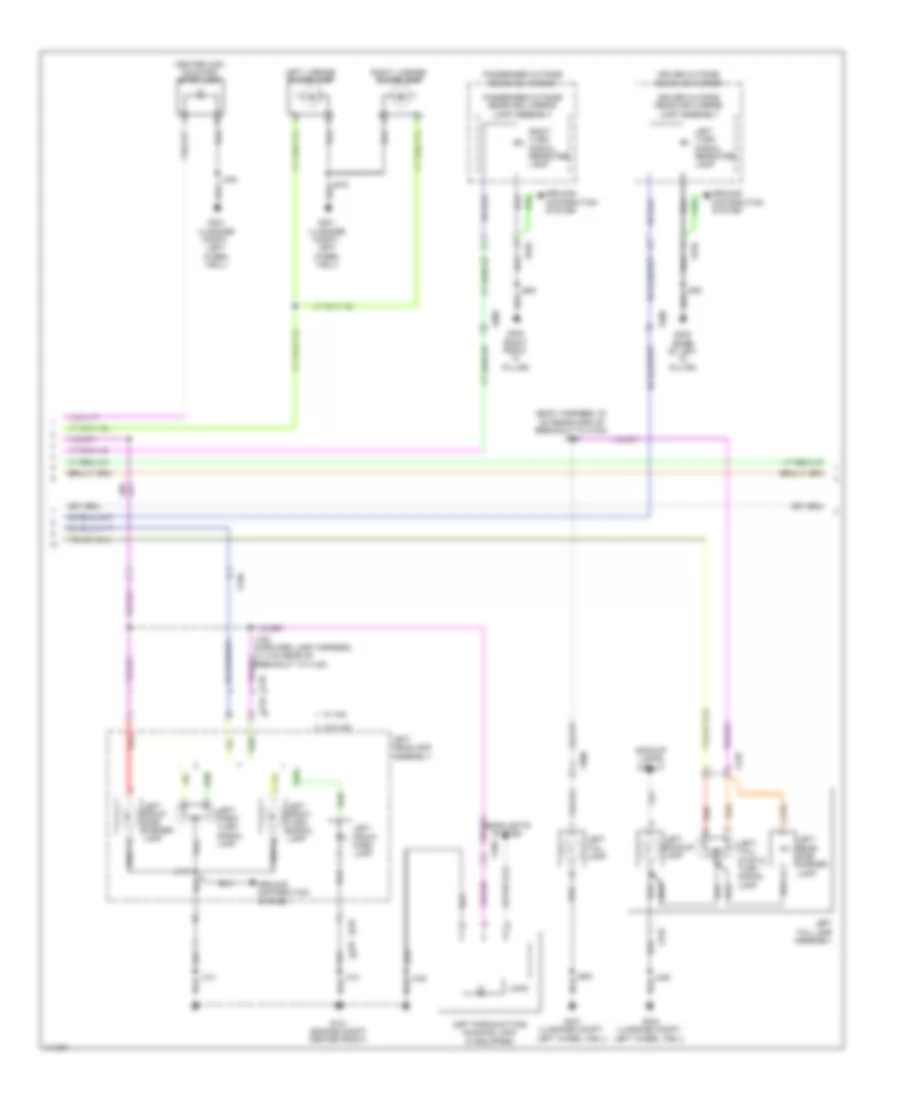
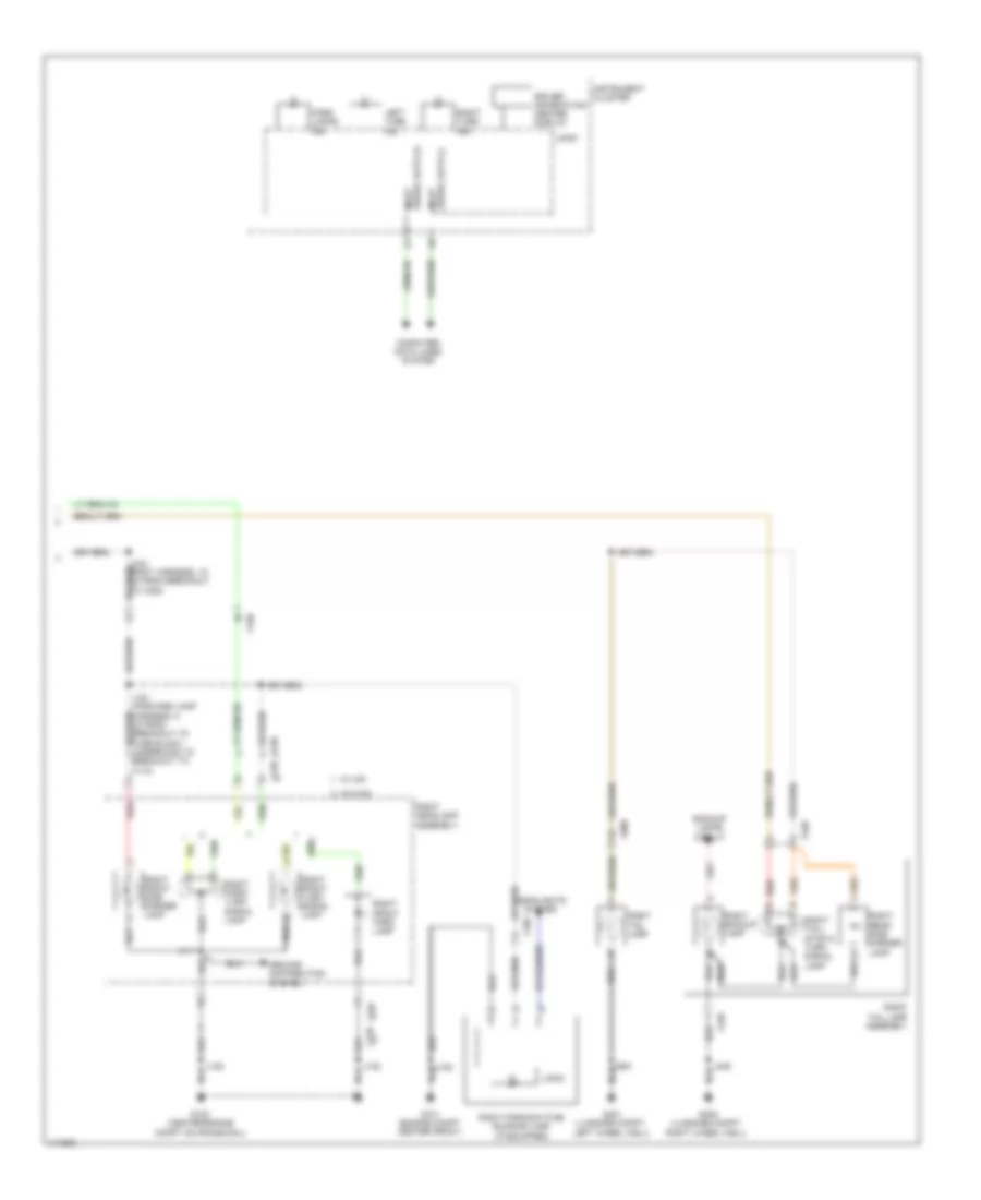
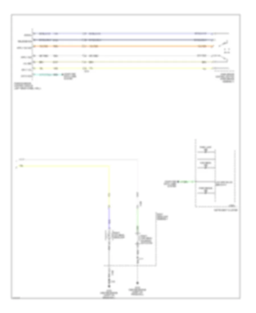
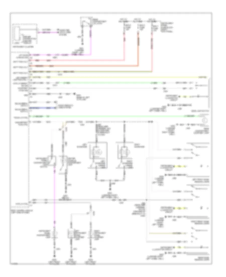
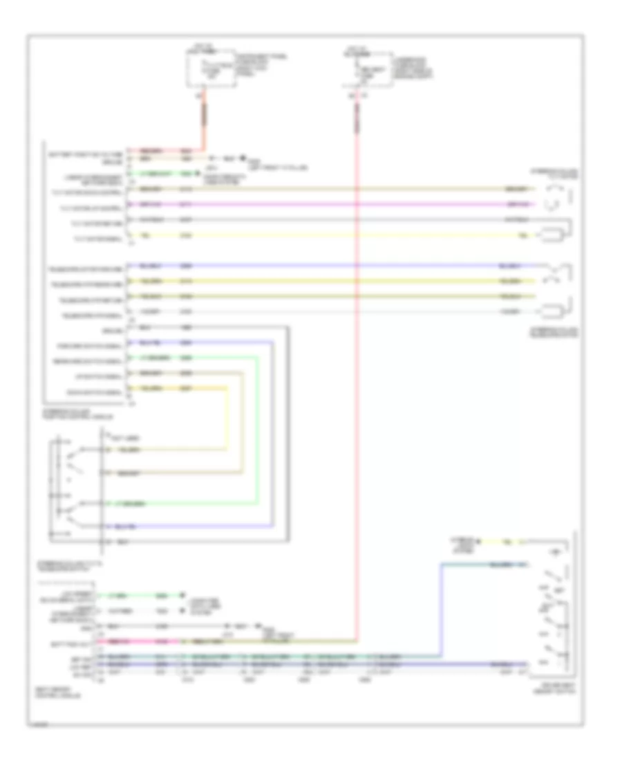
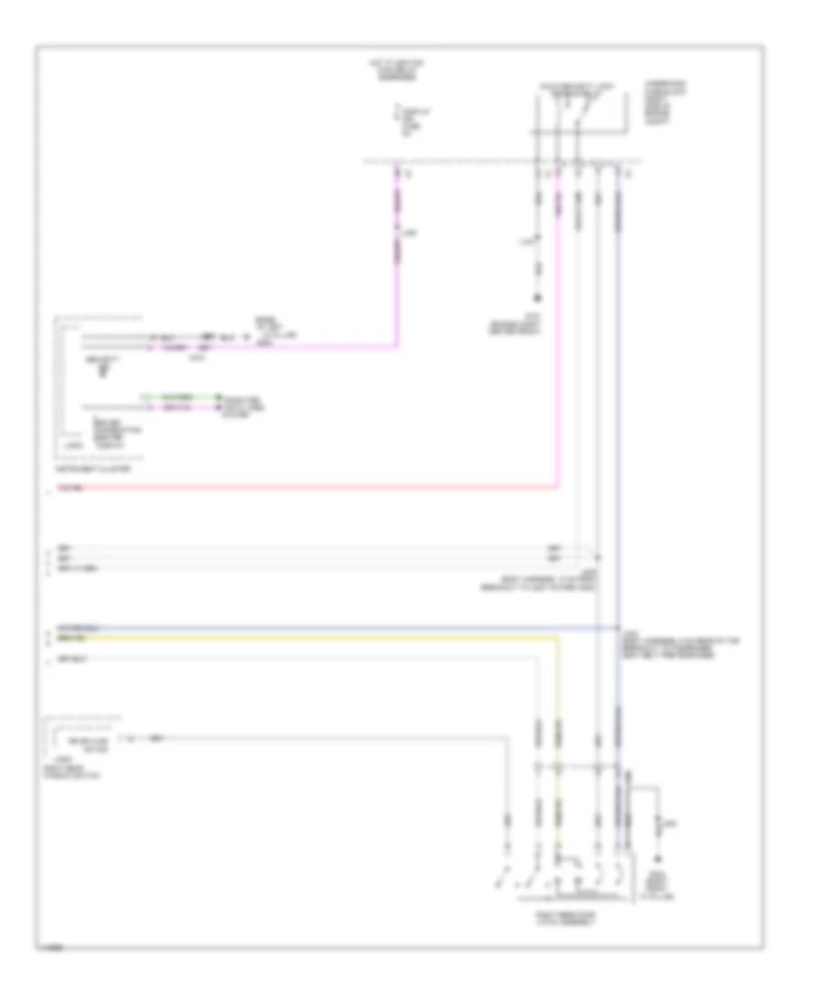
Automatic A/C Wiring Diagram (3 of 4) for Chevrolet Impala LT 2014
List of elements for Automatic A/C Wiring Diagram (3 of 4) for Chevrolet Impala LT 2014:
- (hvac assembly harness, between the breakout to the hvac control module & air temperature sensor - duct left lower) j217
- (on a/c line, under air cleaner) a/c refrigerant pressure sensor
- (right rear side of engine) (2.4l) heater coolant pump
- 2.4l
- A/c evaporator temperature sensor (left side of hvac module)
- Ambient light/sunload sensor (top center of dash)
- Anti-theft system
- Auxiliary heater coolant pump relay
- Battery fuse block
- Cabin cool pmp fuse 5a
- Duct left lower air temperature sensor (left side middle of hvac assembly)
- Duct left upper air temperature sensor (left side top of hvac assembly)
- Duct right lower air temperature sensor (right side middle of hvac assembly)
- Duct right upper air temperature sensor (right side top of hvac assembly)
- Ecm fuse 25a
- Except 2.4l
- Fuse 250a
- G106 (center engine compt on frame rail)
- G122 (rear center engine compt)
- Headlights system
- Hot at all times
- Hot w/ engine controls ignition relay energized
- J120
- Left cooling fan motor (behind left side of radiator)
- Red
- Underhood fuse block (left side of battery)
- X116
- X117
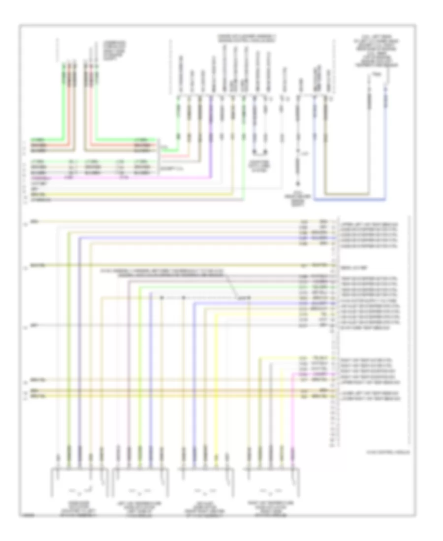
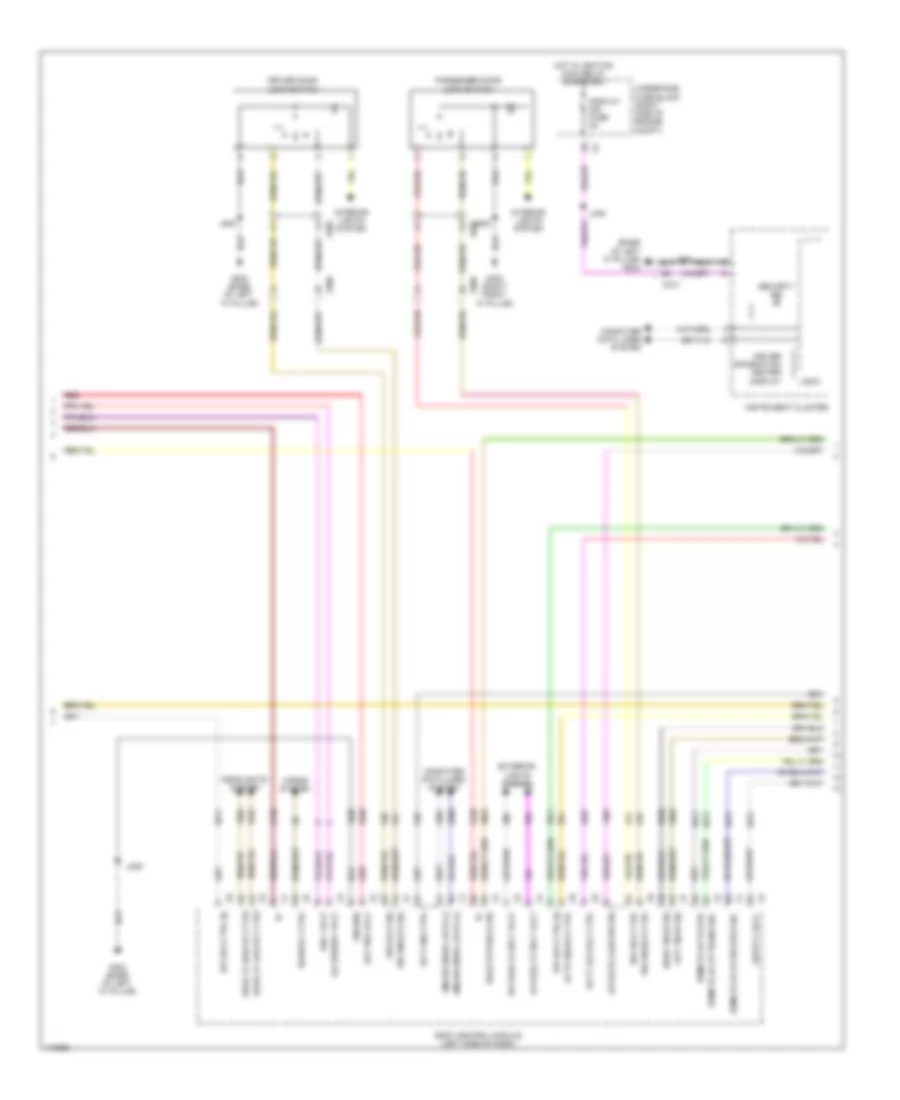
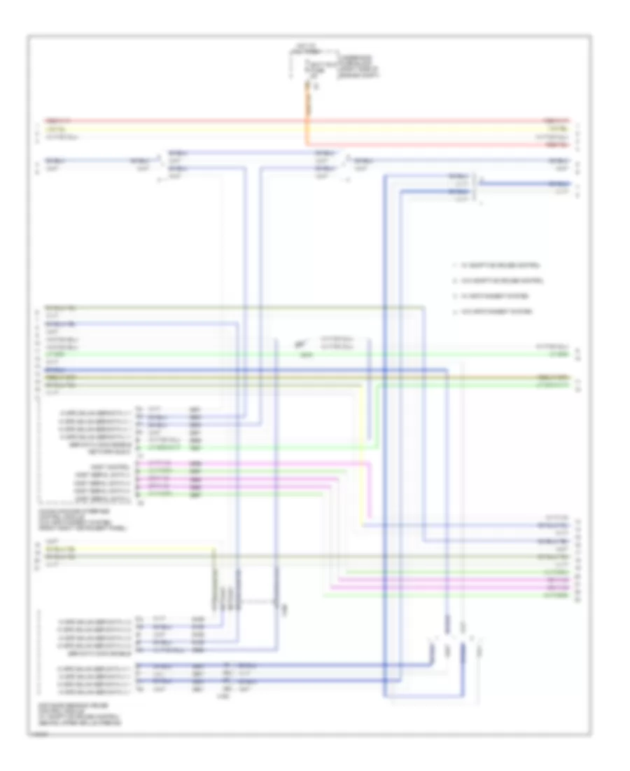
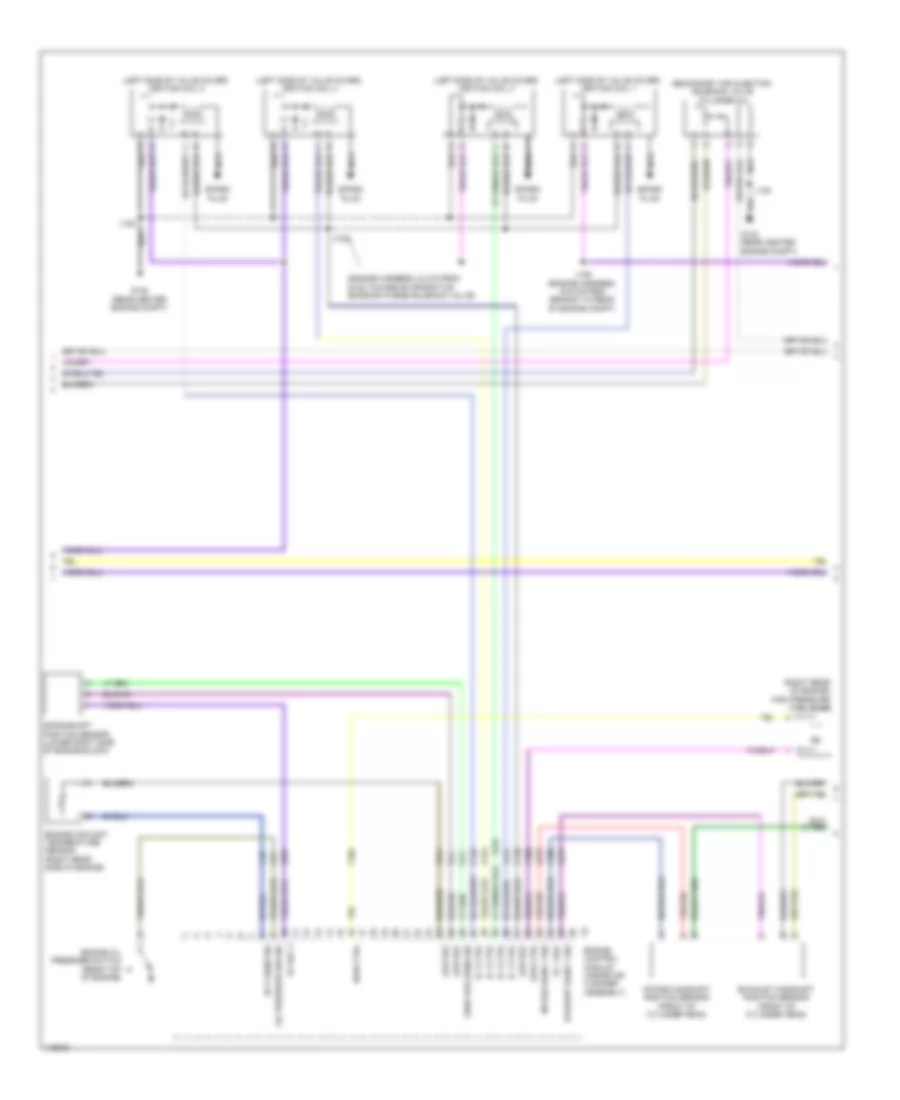
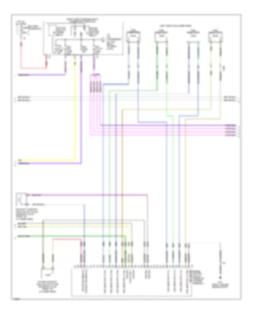
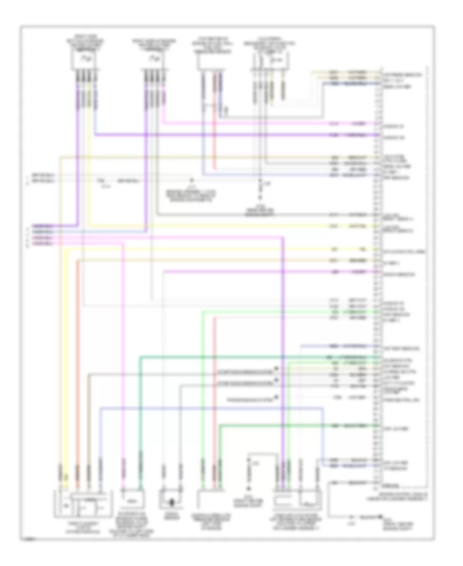
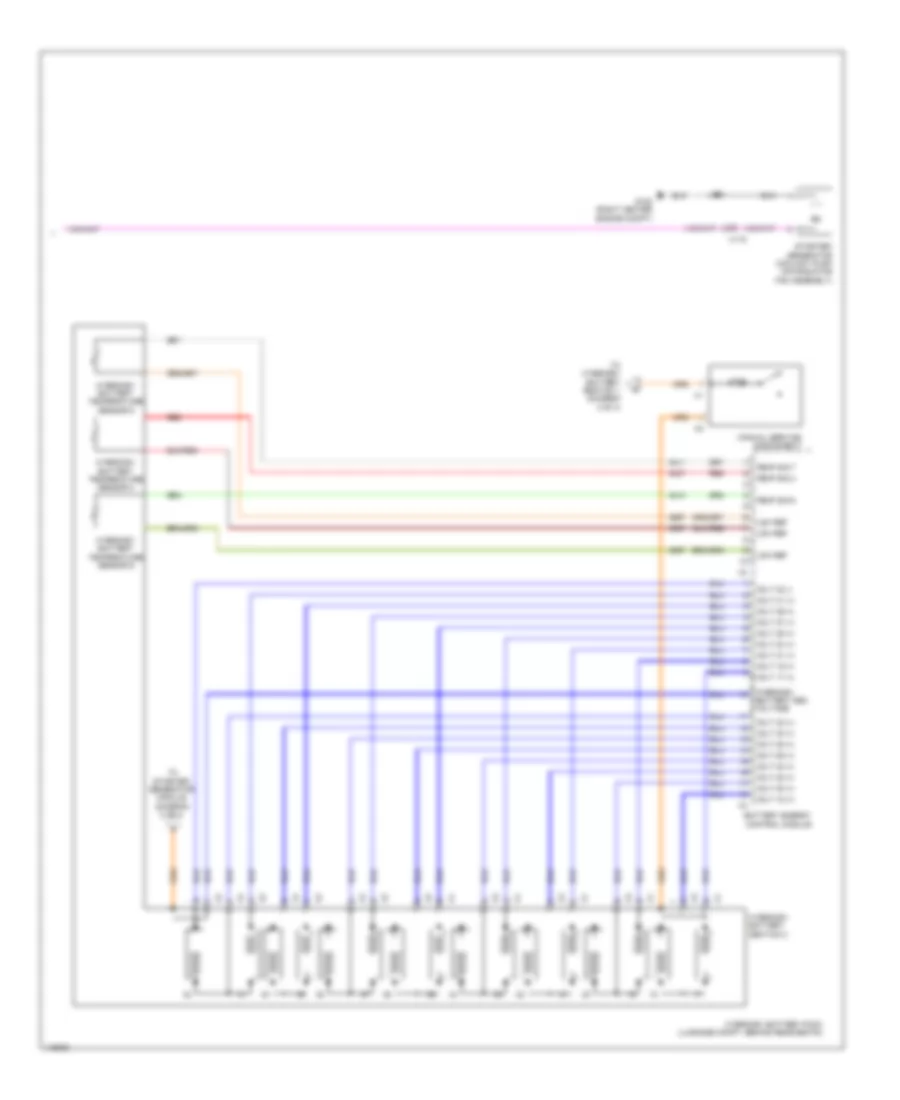
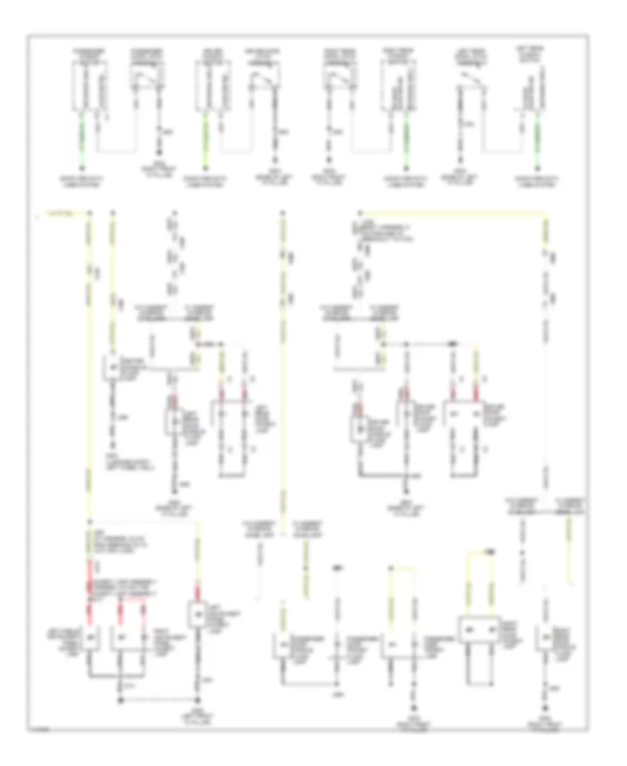
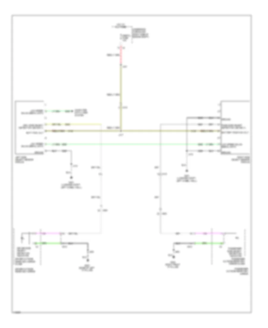
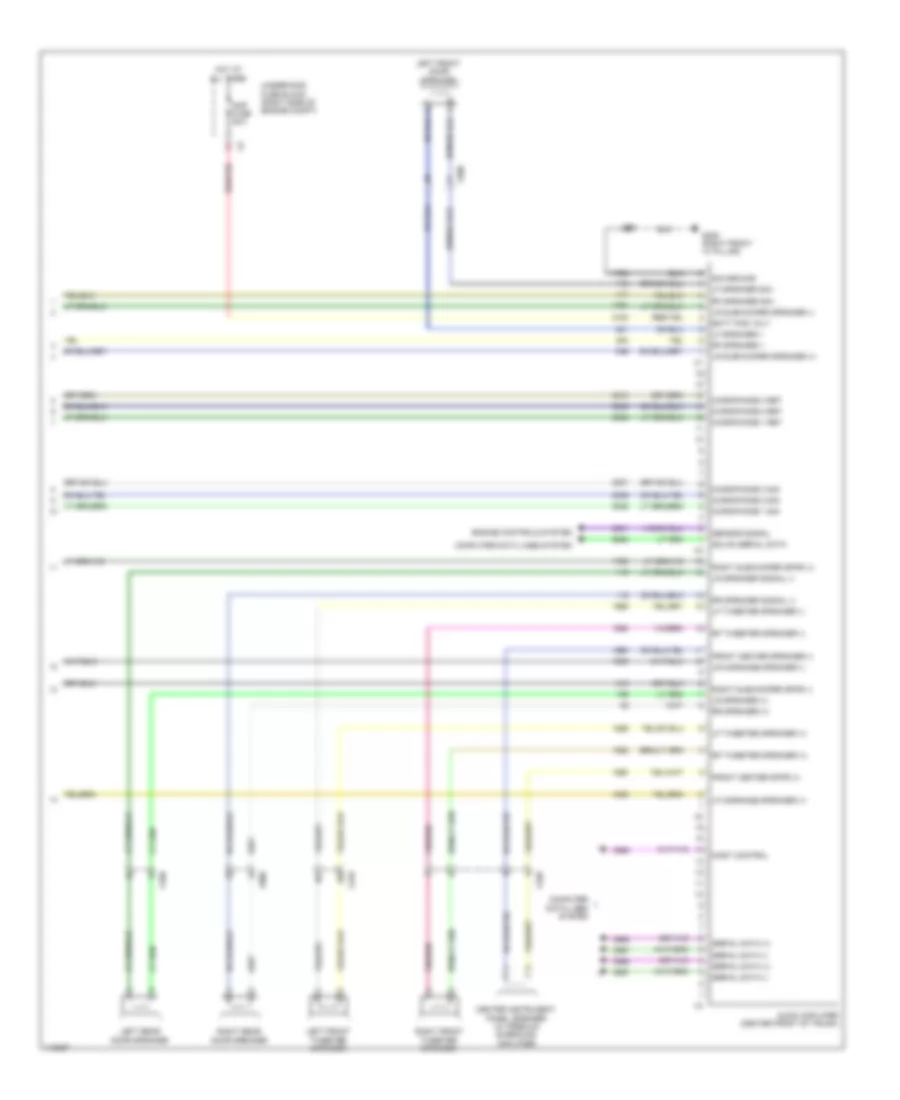
Automatic A/C Wiring Diagram (4 of 4) for Chevrolet Impala LT 2014
List of elements for Automatic A/C Wiring Diagram (4 of 4) for Chevrolet Impala LT 2014:
- (3.6l: left rear of left cylinder head) (except 2.4l: right rear side of engine) (2.5l: rear top of engine) engine coolant temperature sensor
- (hvac assembly harness, between the breakout to the hvac control module & evaporator temperature sensor)
- (inside air cleaner assembly) engine control module (ecm)
- 2.4l
- 5v volt ref
- A/c low ref
- A/c press sens sig
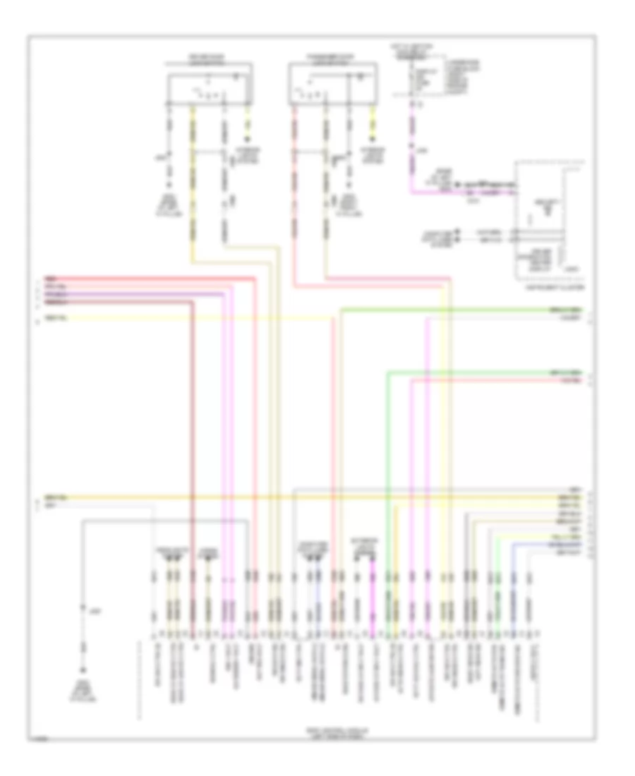
- Air inlet door motor (front right center of hvac assembly)
- Air inlet dr stepper mtr ctrl
- Cmprsr clutch rly ctrl
- Computer data lines system
- Cooling fan relay ctrl hi spd
- Cooling fan relay ctrl lo spd
- Evap core temp sens sig
- Except 2.4l
- G121 (rear center engine compt)
- Gmlan serial data (+)
- Gmlan serial data (-)
- Htr rly ctrl
- Hvac control module
- J121
- J216
- Left air temperature door actuator (left side of hvac module)
- Lower left air temp sens sig
- Lower right air temp sens sig
- Main rly fuse sply
- Mode door actuator (mounted to left of hvac assembly)
- Mode dr stepper motor ctrl
- Right air temp door pos sig
- Right air temp motor ctrl
- Right air temperature door actuator (right side of hvac module)
- Sens lo ref
- Sens low ref
- Sig gnd
- Temp dr stepper motor ctrl
- Temp sens sig eng coolant
- Underhood fuse block (right side of engine compt)
- Upper left air temp sens sig
- Upper right air temp sens sig
- X115
- X150
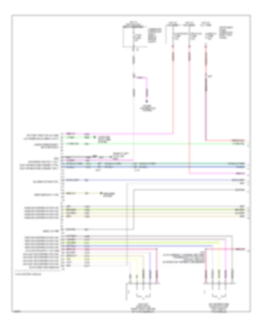
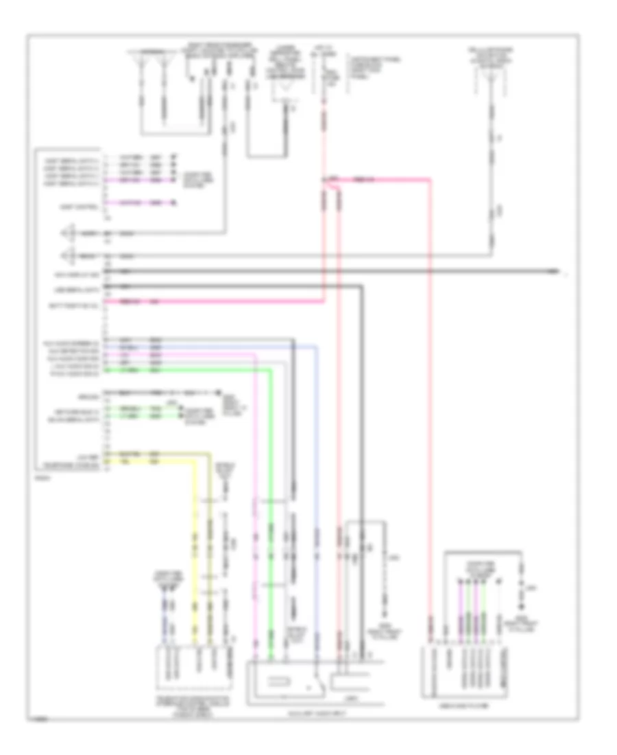
Manual A/C Wiring Diagram (1 of 4) for Chevrolet Impala LT 2014
List of elements for Manual A/C Wiring Diagram (1 of 4) for Chevrolet Impala LT 2014:
- (base of left "a' pillar) g203
- Air inlet door motor (front right center of hvac assembly)
- Air inlet dr stepper mtr ctrl
- Air temperature door actuator (left side of hvac module)
- Battery positive voltage
- Blower mtr spd ctrl
- Computer data lines system
- Defogger system
- Display fuse 15a
- Distribution
- Ele variable displacement ctrl
- Ele variable displacement sply
- Evap core temp sens sig
- Frt/hvac fuse 40a
- Gnd
- Hot at all times
- Hot w/ ignition main relay energized
- Hvac control module
- Hvac/cntrl fuse 10a
- Instrument panel fuse block (right kick panel)
- Ip ign fuse 5a
- J207
- J209
- J216 (hvac assembly harness, between the breakout to the hvac control module & evaporator temperature sensor)
- Linear interconnect network bus 9
- Low speed gmlan serial data
- Mode dr stepper motor ctrl
- Power
- Rear defog rly ctrl
- Run/crank ignition 1 volt
- Sens low ref
- System
- Temp dr stepper motor ctrl
- Underhood fuse block (right side of engine compt)
- X115
- X210
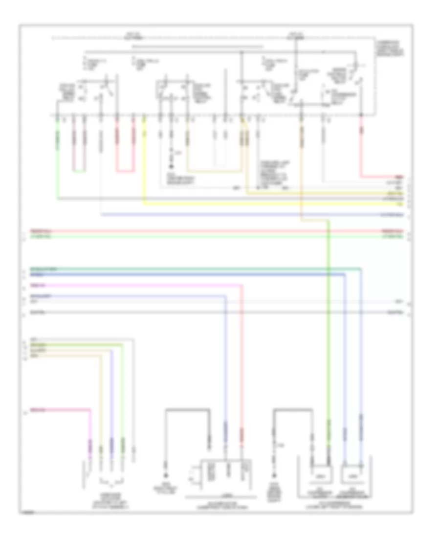
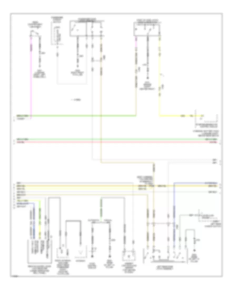
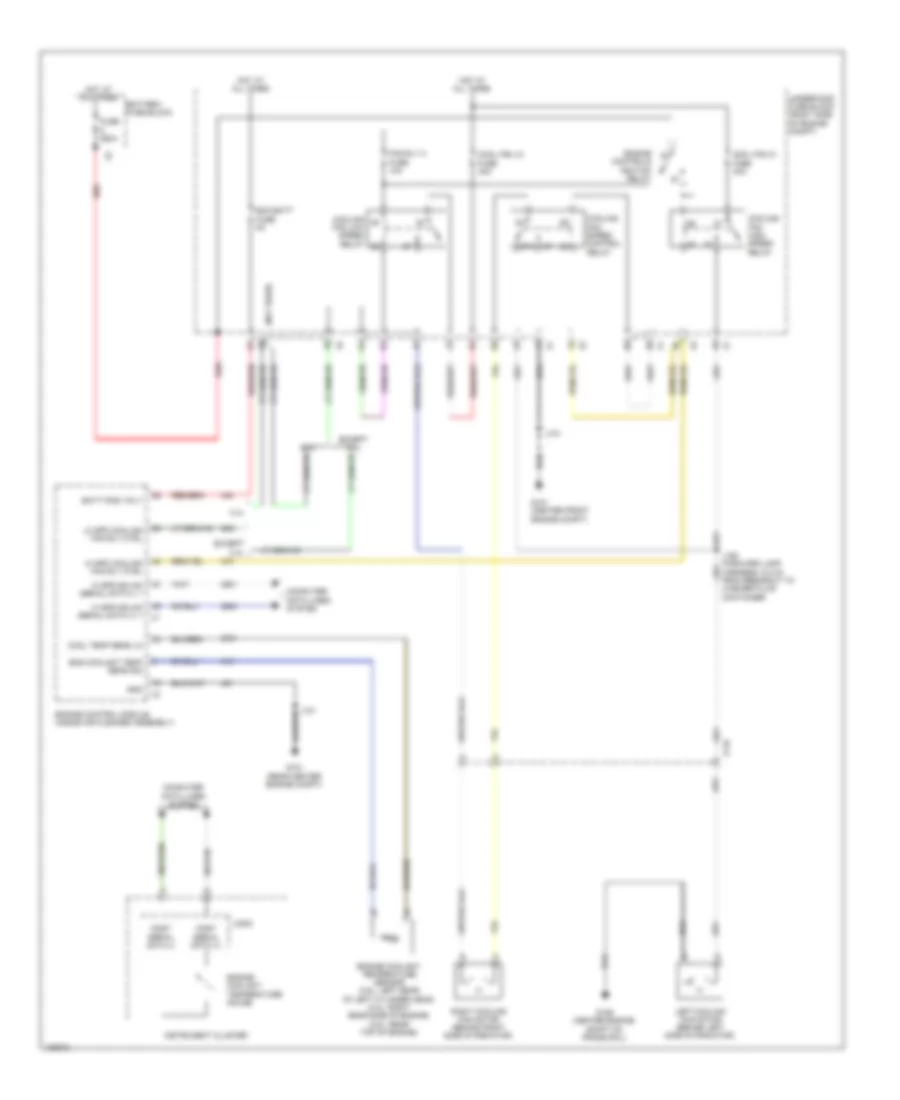
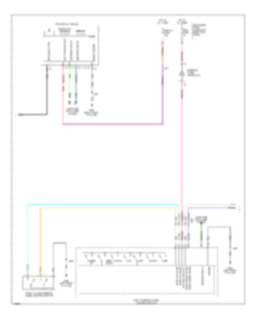
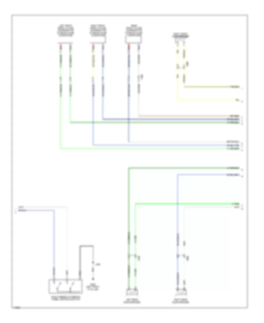
Manual A/C Wiring Diagram (2 of 4) for Chevrolet Impala LT 2014
List of elements for Manual A/C Wiring Diagram (2 of 4) for Chevrolet Impala LT 2014:
- (forward lamp harness, 5.8 cm from breakout to washer fluid container) j150
- 87a
- A/c
- A/c compressor (lower left front of engine)
- A/c compressor clutch
- A/c compressor solenoid valve
- Ac clutch fuse 10a
- Blower motor (under right side of dash)
- Compressor clutch relay
- Cool fan hi fuse 40a
- Cool fan lo fuse 40a
- Cooling fan high speed relay
- Cooling fan low speed relay
- Cooling fan speed control relay
- Engine controls ignition relay
- Fan rly a fuse 10a
- G101 (center front engine compt)
- G122 (rear center engine compt)
- G302 (right front "a" pillar)
- Ground
- Hot at all times
- J101
- J120
- Logic
- Mode door actuator (mounted to left of hvac assembly)
- Nca
- Red
- Spd ctrl blwr mtr
- Underhood fuse block (right side of engine compt)
- Volt batt pos
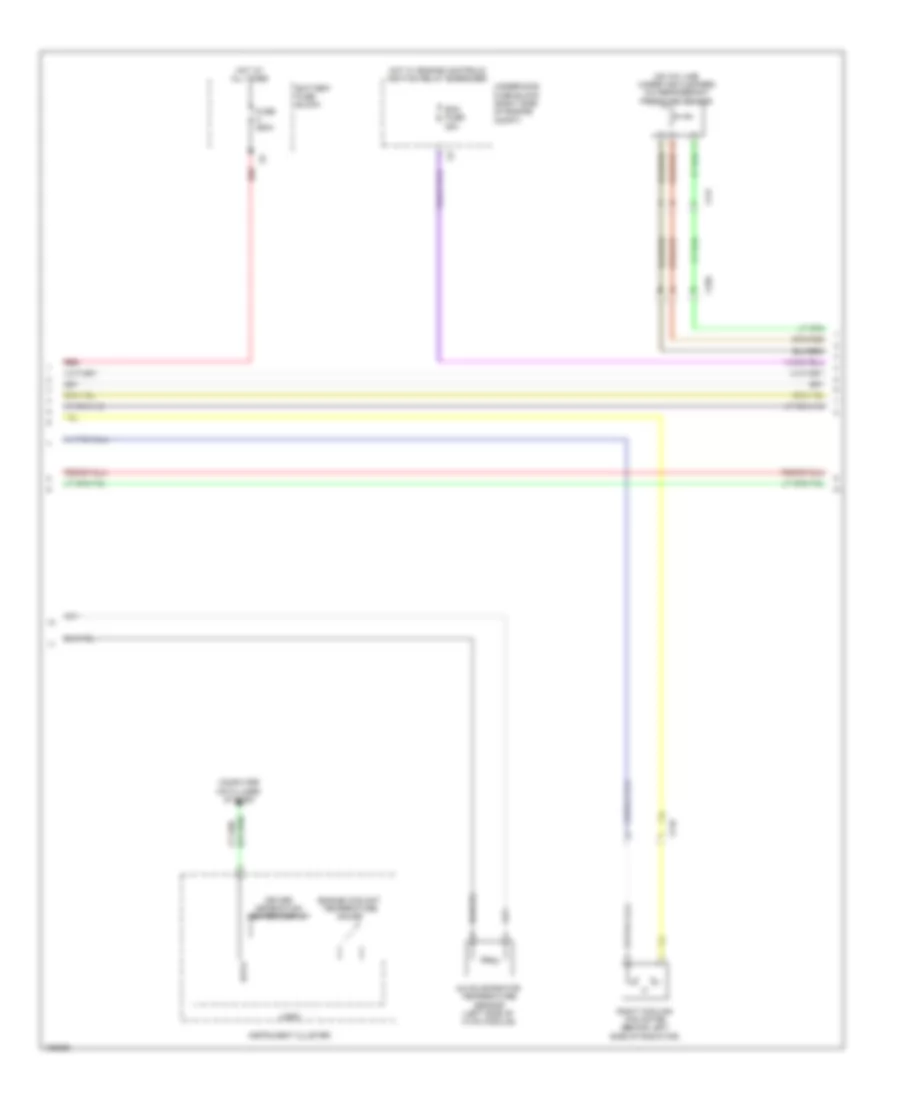
Manual A/C Wiring Diagram (3 of 4) for Chevrolet Impala LT 2014
List of elements for Manual A/C Wiring Diagram (3 of 4) for Chevrolet Impala LT 2014:
- (on a/c line, under air cleaner) a/c refrigerant pressure sensor
- A/c evaporator temperature sensor (left side of hvac module)
- Battery fuse block
- Computer data lines system
- Data
- Driver information center display
- Ecm fuse 25a
- Engine coolant temperature gauge
- Fuse 250a
- Hot at all times
- Hot w/ engine controls ignition relay energized
- Instrument cluster
- Logic
- Red
- Right cooling fan motor (behind left side of radiator)
- Underhood fuse block (right side of engine compt)
- X116
- X117
- X150
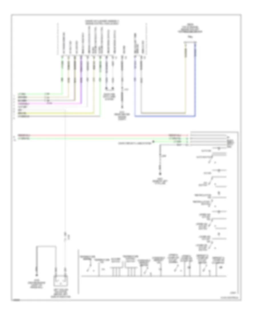
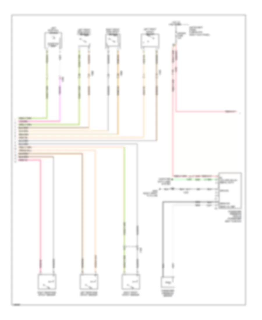
Manual A/C Wiring Diagram (4 of 4) for Chevrolet Impala LT 2014
List of elements for Manual A/C Wiring Diagram (4 of 4) for Chevrolet Impala LT 2014:
- (inside air cleaner assembly) engine control module (ecm)
- (rear top of engine) engine coolant temperature sensor
- 5v volt ref
- A/c ind
- A/c low ref
- A/c press sens sig
- A/c switch
- Auto ind
- Auto switch
- Blower switch
- Bus 9 serial data gnd
- Cmprsr clutch rly ctrl
- Computer data lines system
- Cooling fan relay ctrl hi spd
- Cooling fan relay ctrl lo spd
- Defrost & lower air outlet ind
- Defrost & lower air outlet switch
- G106 (center engine compt on frame rail)
- G121 (rear center engine compt)
- G203 (base of left "a" pillar)
- Gmlan serial data (+)
- Gmlan serial data (-)
- Hvac controls
- J121
- J209
- Left cooling fan motor (behind left side of radiator)
- Logic
- Lower air outlet ind
- Lower air outlet switch
- Main rly fuse sply
- Recirculation ind
- Recirculation switch
- Sens lo ref
- Sens sig eng coolant temp
- Sig gnd
- Temperature control switch
- Temperature ind
- Temperature switch
- Upper & lower air outlet ind
- Upper & lower air outlet switch
- Upper air outlet ind
- Upper air outlet switch
- Windshield defrost ind
- Windshield defrost switch
- X115
- X116
ANTI-LOCK BRAKES
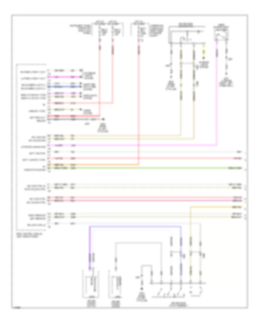
Anti-lock Brakes Wiring Diagram (1 of 2) for Chevrolet Impala LT 2014
List of elements for Anti-lock Brakes Wiring Diagram (1 of 2) for Chevrolet Impala LT 2014:
- 5v ref
- Abs pump fuse 60a
- Abs valve fuse 30a
- B+ volt
- Brake booster pump motor (right front wheel well)
- Brake booster pump motor relay
- Brake fluid level switch (on brake fluid reservoir)
- Brake pressure modulator (left rear of engine compt)
- Brk fluid lvl sens sig
- Brk vac pmp fuse 20a
- Computer data lines system
- Electronic brake control module (in brake pressure modulator valve)
- G102 (center engine compt on frame rail)
- G110 (left front of engine compt)
- G305 (left front "a" pillar)
- Gnd
- Hi spd gmlan serial data +
- Hi spd gmlan serial data -
- Hot at all times
- J102
- J229
- Left front wheel speed sensor (left front wheel hub assemblies)
- Left rear wheel speed sensor (left rear wheel hub assemblies)
- Lf wheel spd sens sig
- Lf wheel spd sens sply volt
- Low ref
- Lr wheel spd sens sig
- Lr wheel spd sens sply volt
- Red
- Rf wheel spd sens sig
- Rf wheel spd sens sply volt
- Right front wheel speed sensor (right front wheel hub assemblies)
- Right rear wheel speed sensor (right rear wheel hub assemblies)
- Rr wheel spd sens sig
- Rr wheel spd sens sply volt
- Sens sig
- Serial data communication enable
- Steering angle snsr sply volt
- Switch sig
- Underhood fuse block (right side of engine compt)
- X150
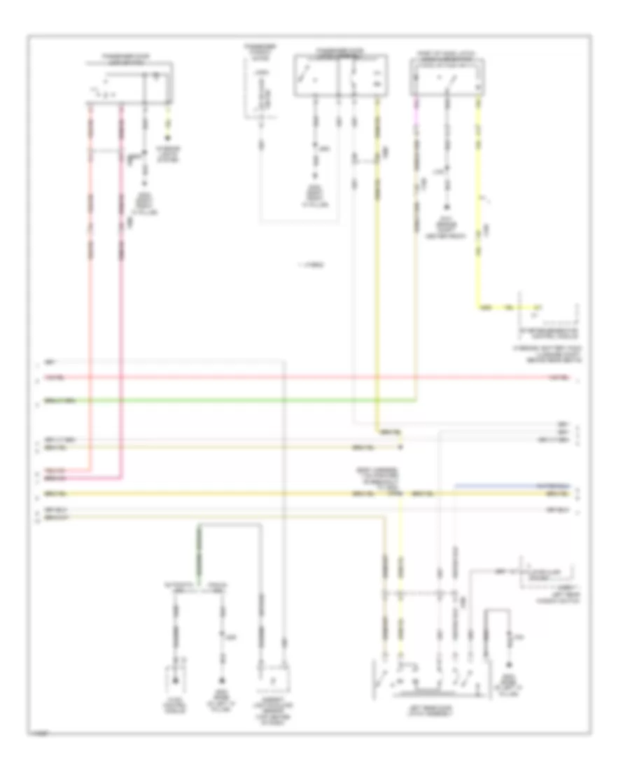
Anti-lock Brakes Wiring Diagram (2 of 2) for Chevrolet Impala LT 2014
List of elements for Anti-lock Brakes Wiring Diagram (2 of 2) for Chevrolet Impala LT 2014:
- 5v ref
- Abs ind
- Body control module (left side of dash)
- Brake booster vacuum sensor (left rear engine compt)
- Brake ind
- Brake pedal position sensor (top of brake pedal assembly)
- Brk position sens sig
- Center console multi-function switch
- Computer data lines system
- Computer data lines systems
- Cruise/etc/tcc brk sig
- Driver information center display
- Engine control module (ecm) (inside air cleaner assembly)
- Esc ind
- Esc off ind
- G203 (base of left "a" pillar)
- G307 (below driver seat)
- Gnd
- Hi spd gmlan serial data +
- Hi spd gmlan serial data -
- Hybrid
- Hybrid/ev battery pack (luggage compt, behind rear seats)
- Hybrid/ev powertrain control module
- Instrument cluster
- J209
- J300
- Logic
- Low reference
- Most serial data (+)
- Most serial data (-)
- Serial data communication enable x4
- Steering angle sensor (base of steering column)
- Steering angle snsr sply volt
- Traction control off switch
- Traction ctrl sw sig
- Traction off ind
- X115
- X210
- X300
ANTI-THEFT
Forced Entry Wiring Diagram, with Passive Keyless Entry (1 of 4) for Chevrolet Impala LT 2014
List of elements for Forced Entry Wiring Diagram, with Passive Keyless Entry (1 of 4) for Chevrolet Impala LT 2014:
- Accessory volt
- Antenna 1 sig hi
- Antenna 1 sig lo
- Antenna 2 sig hi
- Antenna 2 sig lo
- Antenna 3 sig hi
- Antenna 3 sig lo
- Bat pos volt
- Batt rvc fuse 5a
- Bcm 3 fuse 15a
- Bcm 5 fuse 15a
- Center console front keyless entry antenna (mounted to rear of hvac assembly)
- Center console rear keyless entry antenna (rear of center console compt)
- Computer data lines system
- Driver door latch assembly
- Driver window motor
- Driver window switch
- G203 (base of left "a" pillar)
- G302 (right front "a" pillar)
- Ground
- Hot at all times
- Ign 1 volt
- Ignition mode switch
- Instrument panel fuse block (right kick panel)
- J234
- J500
- Keyless entry control module (right a-pillar)
- Lo spd gmlan ser data
- Logic
- Mtr status
- Passive start sw 2 low ref
- Passive start sw sig 2
- Peps batt fuse 5a
- Rear compartment keyless entry antenna (front center of luggage compt)
- Red
- Sw sig
- Sw sig lf dr ajar
- Underhood fuse block (right side of engine compt)
- X210
- X300
- X500
- X505
Forced Entry Wiring Diagram, with Passive Keyless Entry (2 of 4) for Chevrolet Impala LT 2014
List of elements for Forced Entry Wiring Diagram, with Passive Keyless Entry (2 of 4) for Chevrolet Impala LT 2014:
- (base of left "a" pillar) g203
- Accessory volt
- Actr unlock ctrl
- Bat pos volt
- Body control module (left side of dash)
- Computer data lines system
- Display ign fuse 5a
- Dr lock ctrl (2)
- Driver door lock switch
- Driver information center display
- Exterior lights system
- G203 (base of left "a" pillar)
- G302 (right front "a" pillar)
- Gmlan serial data (+)
- Gmlan serial data (-)
- Ground
- Head lp high rly ctrl
- Head lp low rly ctrl
- Headlights system
- Hood status b sig
- Horn rly ctrl
- Horns system
- Hot w/ ignition main relay energized
- Ign 1 volt
- Instrument cluster
- Interior lights system
- J209
- J339
- J505
- J605
- Left rear sig
- Lh park lp sply volt
- Liftgate ajar sw sig
- Logic
- Passenger door lock switch
- Red
- Remote actr receive sig
- Remote actr rtn
- Remote actr trans sig
- Rh park lp sply volt
- Right rear sig
- Scty ind ctrl
- Scty lock rly ctrl
- Security ind
- Sw lock ctrl
- Sw lock sig
- Sw unlock ctrl
- Sw unlock sig
- Underhood fuse block (right side of engine compt)
- X210
- X500
- X505
- X600
- X605
Forced Entry Wiring Diagram, with Passive Keyless Entry (3 of 4) for Chevrolet Impala LT 2014
List of elements for Forced Entry Wiring Diagram, with Passive Keyless Entry (3 of 4) for Chevrolet Impala LT 2014:
- (body harness, 7 cm forward of breakout to x800) j346
- (part of hood latch) hood ajar switch
- Ambient light/sunload sensor (top center of dash)
- Antenna
- Automatic a/c
- Coax
- Fm/rfr
- G101 (engine compt center front)
- G203 (base of left "a" pillar)
- G302 (right front "a" pillar)
- G401 (luggage compt, left wheelwell)
- Hvac control module
- Hybrid
- Hybrid/ev battery pack (luggage compt, behind rear seats)
- J100
- J209
- J600
- J700
- J900
- Left rear door latch assembly
- Left rear window switch
- Logic
- Lr dr ajar sw sig
- Manual a/c
- Passenger door latch assembly
- Passenger window switch
- Radio antenna amplifier (right rear passenger compt, mounted to c-pillar)
- Rear compartment lid latch
- Receive sig remote actr
- Remote actr rtn
- Remote control door lock receiver (under defroster grill panel)
- Rf dr ajar sw sig
- Rfr
- Starter/generator control module
- Trans sig remote actr
- X150
- X210
- X600
- X700
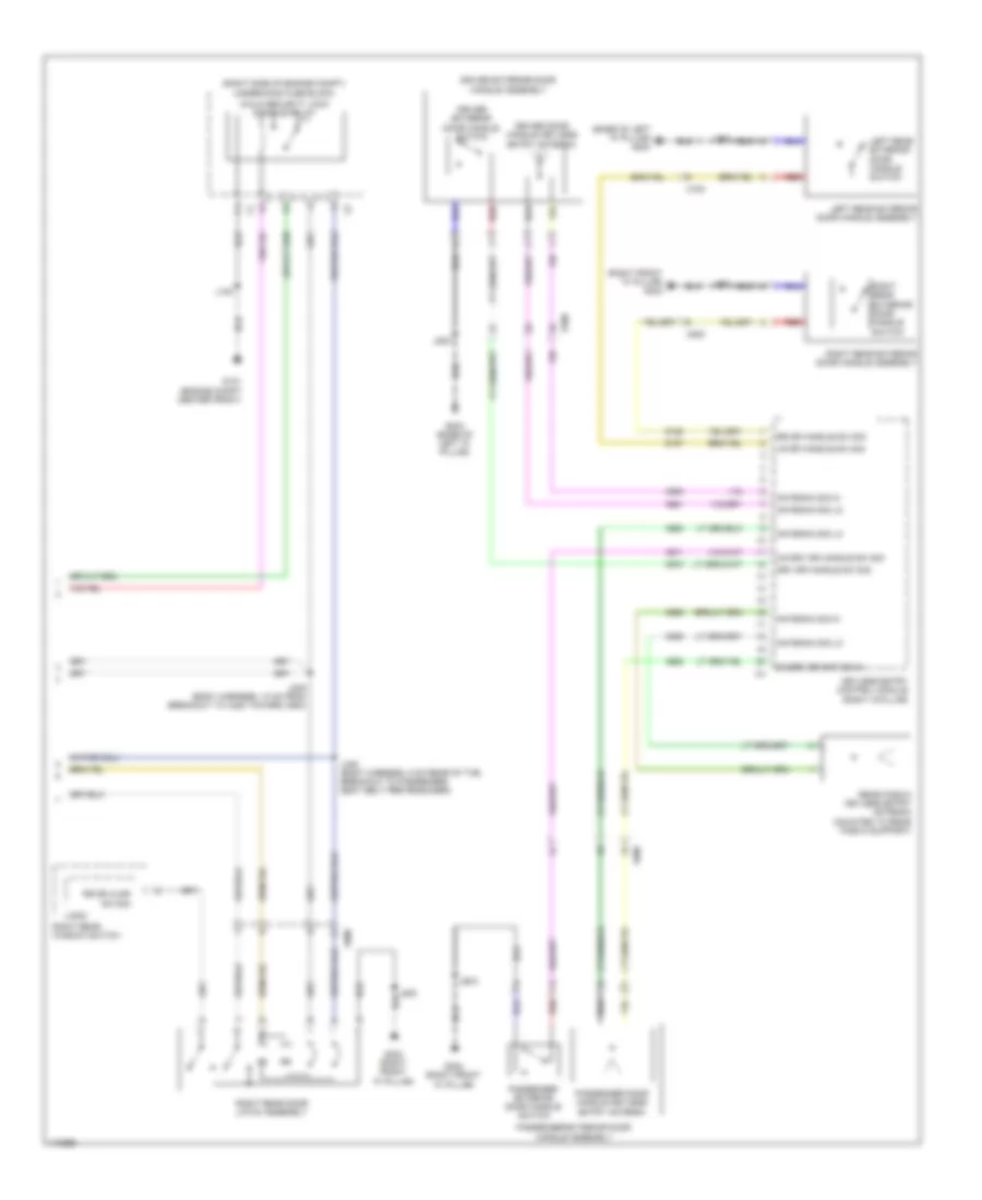
Forced Entry Wiring Diagram, with Passive Keyless Entry (4 of 4) for Chevrolet Impala LT 2014
List of elements for Forced Entry Wiring Diagram, with Passive Keyless Entry (4 of 4) for Chevrolet Impala LT 2014:
- (base of left "a" pillar) g203
- (right front "a" pillar) g302
- (right side of engine compt) underhood fuse block
- Antenna sig hi
- Antenna sig lo
- Child security lock disable relay
- Co-drv dr ant sig hi
- Co-drv dr handle sw sig
- Driver door handle keyless entry antenna
- Driver exterior door handle assembly
- Driver exterior door handle switch
- Drv dr handle sw sig
- G101 (engine compt center front)
- G203 (base of left "a" pillar)
- G302 (right front "a" pillar)
- J100
- J235 (body harness, 12 cm from breakout to x220 toward x600)
- J345 (body harness, 5 cm rear of the breakout to passenger seat belt pretensioner)
- J500
- J600
- J700
- J800
- Keyless entry control module (right a-pillar)
- Left rear exterior door handle assembly
- Left rear exterior door handle switch
- Logic
- Lr dr handle sw sig
- Passenger door handle keyless entry antenna
- Passenger exterior door handle assembly
- Passenger exterior door handle switch
- Rear fascia keyless entry antenna (mounted to rear fascia support)
- Red
- Right rear door latch assembly
- Right rear exterior door handle assembly
- Right rear exterior door handle switch
- Right rear window switch
- Rr dr ajar sw sig
- Rr dr handle sw sig
- X500
- X600
- X700
- X800
Forced Entry Wiring Diagram, without Passive Keyless Entry (1 of 3) for Chevrolet Impala LT 2014
List of elements for Forced Entry Wiring Diagram, without Passive Keyless Entry (1 of 3) for Chevrolet Impala LT 2014:
- Actr unlock ctrl
- Bat pos volt
- Batt rvc fuse 5a
- Bcm 3 fuse 15a
- Bcm 5 fuse 15a
- Body control module (left side of dash)
- Computer data lines
- Dr lock ctrl (2)
- Driver door latch assembly
- Driver door lock switch
- Driver window motor
- Driver window switch
- Exterior lights
- G203 (base of left "a" pillar)
- G401 (luggage compt, left wheelwell)
- Gmlan serial data (+)
- Gmlan serial data (-)
- Ground
- Head lp high rly ctrl
- Head lp low rly ctrl x5
- Headlights system
- Hood status b sig
- Horn rly ctrl
- Horns system
- Hot at all times
- Instrument panel fuse block (right kick panel)
- Interior lights system
- J209
- J500
- J505
- J900
- Left rear sig
- Lh park lp sply volt
- Liftgate ajar sw sig
- Logic
- Mtr status
- Rear compartment lid latch
- Red
- Rh park lp sply volt
- Right rear sig
- Scty ind ctrl
- Scty lock rly ctrl
- Sw lock ctrl
- Sw lock sig
- Sw sig
- Sw sig lf dr ajar
- Sw unlock ctrl
- Sw unlock sig
- System
- Underhood fuse block (right side of engine compt)
- X500
- X505
Forced Entry Wiring Diagram, without Passive Keyless Entry (2 of 3) for Chevrolet Impala LT 2014
List of elements for Forced Entry Wiring Diagram, without Passive Keyless Entry (2 of 3) for Chevrolet Impala LT 2014:
- (body harness, 7 cm forward of breakout to x800) j346
- (part of hood latch) hood ajar switch
- Ambient light/sunload sensor (top center of dash)
- Automatic a/c
- G101 (engine compt center front)
- G203 (base of left "a" pillar)
- G302 (right front "a" pillar)
- Hvac control module
- Hybrid
- Hybrid/ev battery pack (luggage compt, behind rear seats)
- Interior lights system
- J100
- J209
- J600
- J605
- J700
- Left rear door latch assembly
- Left rear window switch
- Logic
- Lr dr ajar sw sig
- Manual a/c
- Passenger door latch assembly
- Passenger door lock switch
- Passenger window motor
- Rf dr ajar sw sig
- Starter/generator control module
- X150
- X600
- X605
- X700
Forced Entry Wiring Diagram, without Passive Keyless Entry (3 of 3) for Chevrolet Impala LT 2014
List of elements for Forced Entry Wiring Diagram, without Passive Keyless Entry (3 of 3) for Chevrolet Impala LT 2014:
- "a" pillar)
- (base
- Center display
- Child security lock disable relay
- Computer
- Data lines
- Display ign fuse 5a
- Driver
- G101 (engine compt center front)
- G203
- G302 (right front "a" pillar)
- Hot w/ ignition main relay energized
- Information
- Instrument cluster
- J100
- J209
- J235 (body harness, 12 cm from breakout to x220 toward x600)
- J339
- J345 (body harness, 5 cm rear of the breakout to passenger seat belt pretensioner)
- J800
- Logic
- Of left
- Right rear door latch assembly
- Right rear window switch
- Rr dr ajar sw sig
- Security ind
- System
- Underhood fuse block (right side of engine compt)
- X210
- X800
Pass-Key Wiring Diagram for Chevrolet Impala LT 2014
List of elements for Pass-Key Wiring Diagram for Chevrolet Impala LT 2014:
- (base of left "a" pillar) g203
- (part of hood latch) hood ajar switch
- Bat pos volt
- Batt rvc fuse 5a
- Battery positive volt
- Bcm 3 fuse 15a
- Bcm 5 fuse 15a
- Body control module (left side of dash)
- Computer data lines
- Computer data lines system
- Display ign fuse 5a
- Driver information center display
- G101 (engine compt center front)
- G203 (base of left "a" pillar)
- Gmlan serial data (+)
- Gmlan serial data (-)
- Ground
- Hood status a signal
- Hood status b sig
- Hot at all times
- Hot w/ ignition main relay energized
- Hybrid
- Hybrid/ev battery pack (luggage compt, behind rear seats)
- Immobilizer control module (w/ keyless: inside center console) (w/o keyless: within steering column)
- Instrument cluster
- Instrument panel fuse block (right kick panel)
- J100
- J209
- J339
- Linear interconnect network bus 11
- Logic
- Red
- Security ind
- Starter/generator control module
- System
- Underhood fuse block (right side of engine compt)
- Vehicle anti-theft sys immobilizer rtn
- Vehicle anti-theft sys immobilizer volt
- Vehicle anti-theft sys immobilizer volt x3
- W/ keyless engine start
- X150
- X210
- X300
BODY CONTROL MODULES
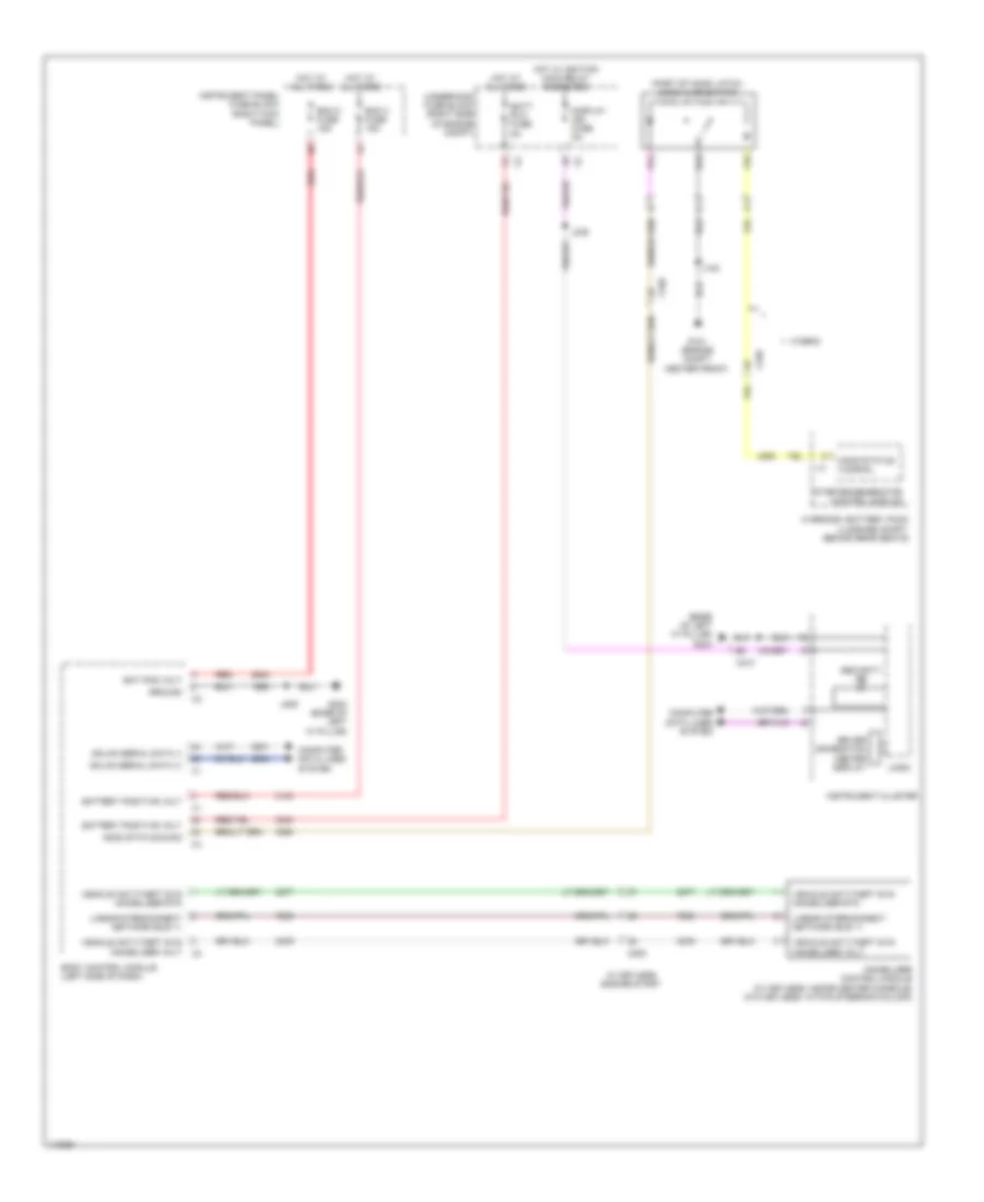
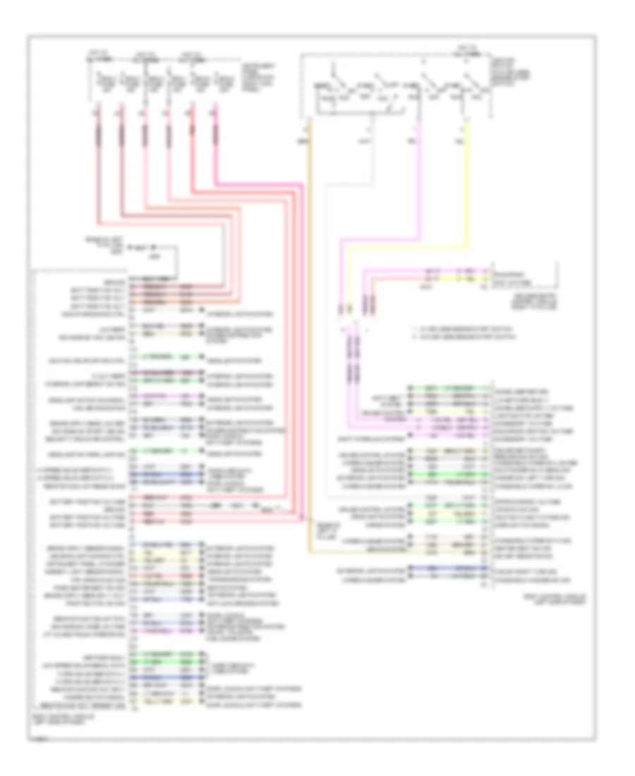
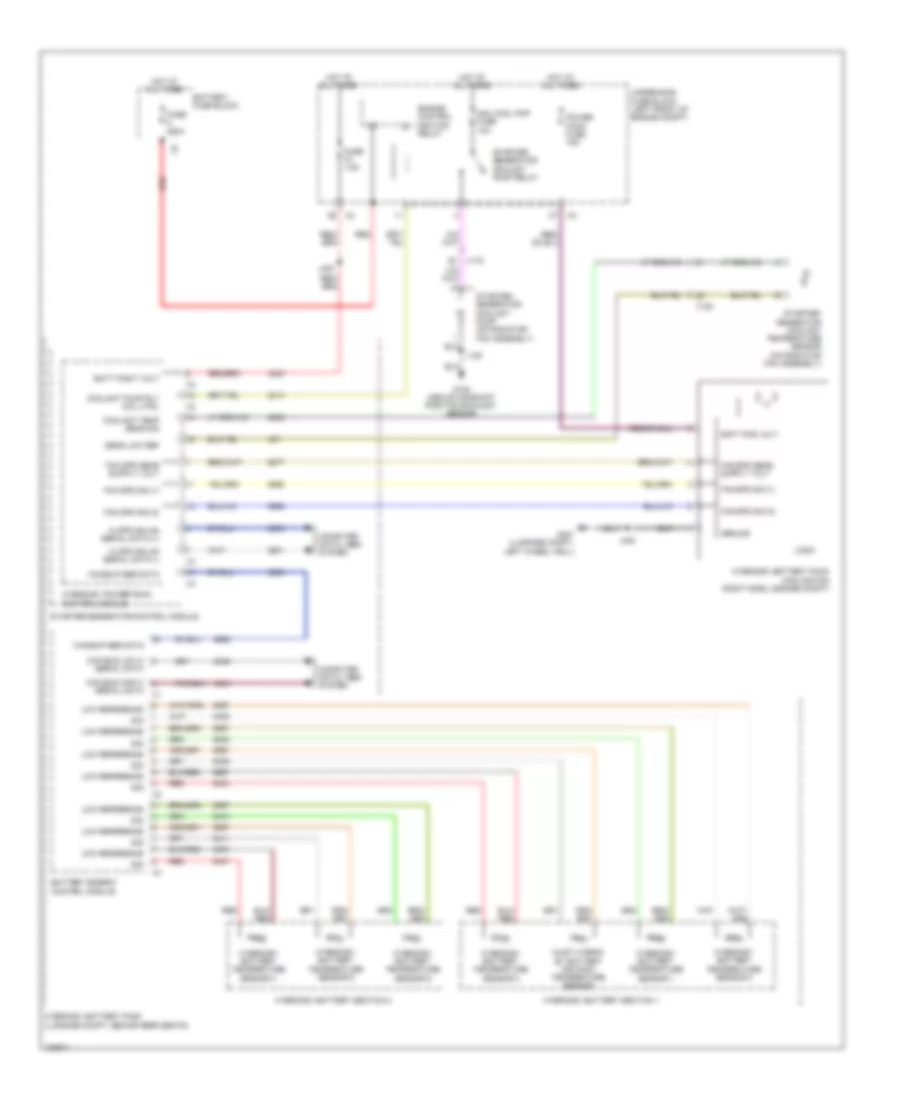
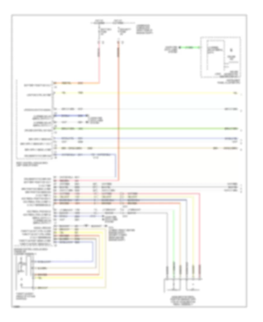
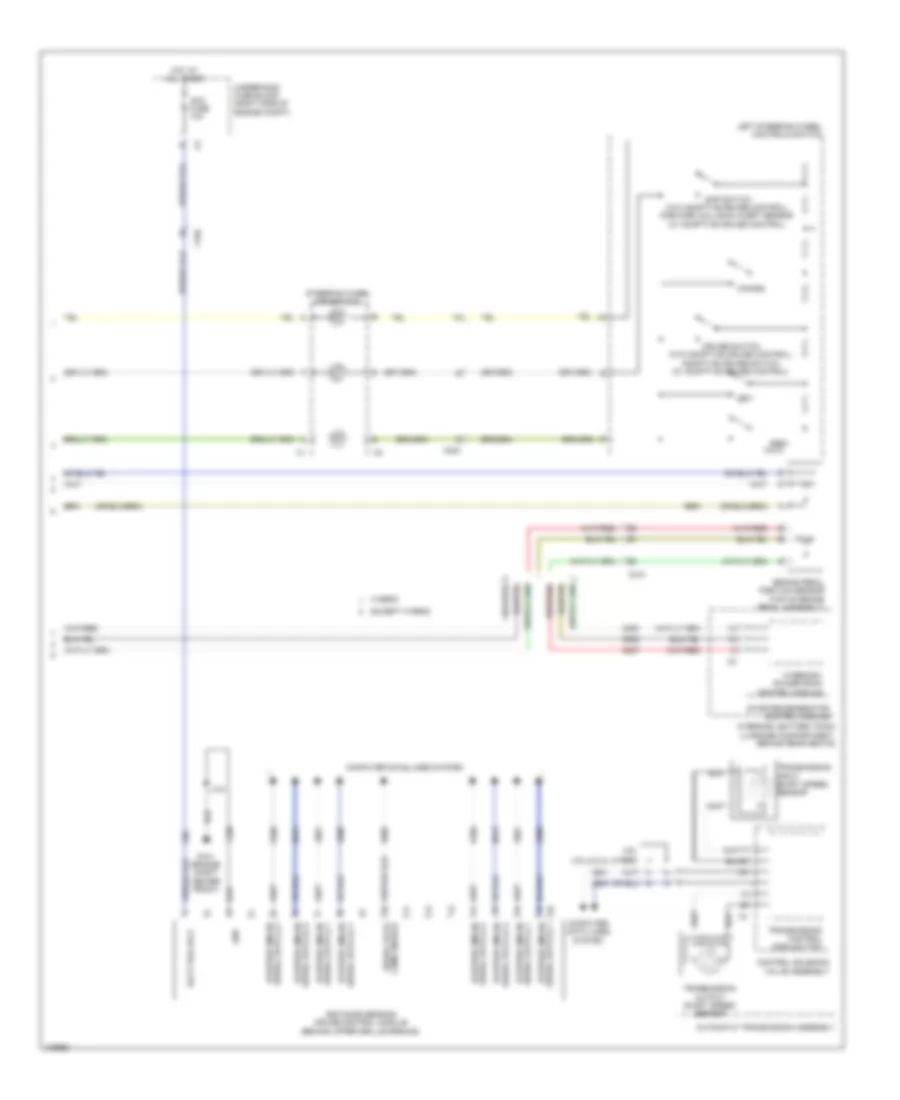
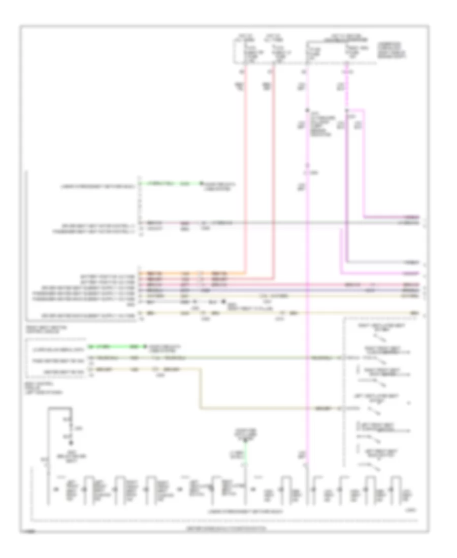
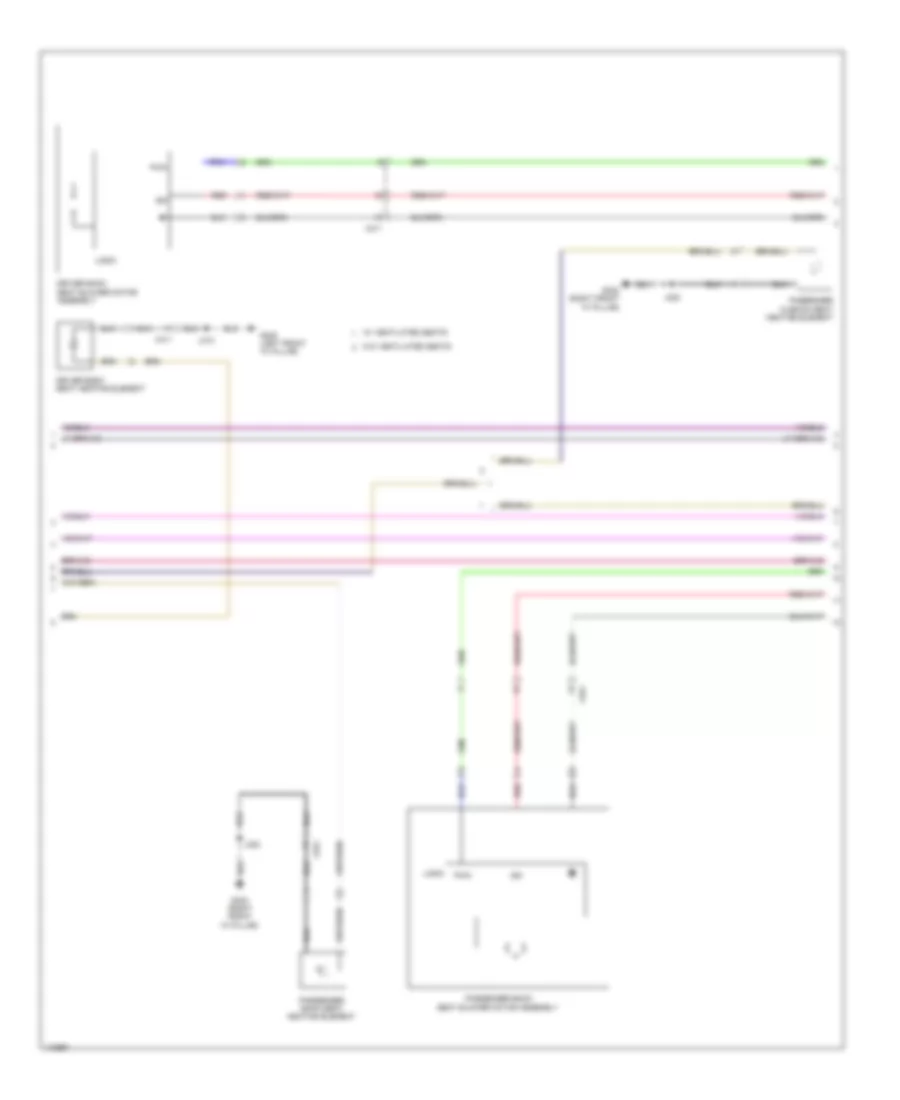
Body Control Modules Wiring Diagram (1 of 2) for Chevrolet Impala LT 2014
List of elements for Body Control Modules Wiring Diagram (1 of 2) for Chevrolet Impala LT 2014:
- (base of left "a" pillar)
- (base of left "a" pillar) g203
- 5 volt refr
- Acc
- Acc voltage
- Accessory voltage
- Ambient light sensor signal
- Anti-lock brakes system
- Anti-theft system
- Batt positive volt
- Battery positive voltage
- Bcm 1 fuse 15a
- Bcm 2 fuse 15a
- Bcm 3 fuse 15a
- Bcm 4 fuse 15a
- Bcm 5 fuse 15a
- Bcm 8 fuse 30a
- Body control module (left side of dash)
- Computer data lines system
- Cruise control system
- Cruise set/coast/ resume/acc sw sig
- Door locks & anti-theft systems
- Door locks & anti-theft systems power distribution system trunk, tailgate, fuel doors system
- Exterior lights system
- G203
- Ground
- Haz led dimming sig
- Haz sw right turn sig
- Hazard sw left turn sig
- Hazard switch signal
- Hdlp dimmer sw hi beam sig
- Hdlp sw flash to pass sig
- Hdlp sw hdlps off sig ctrl
- Headlamp sw park lamp sig
- Headlamp switch on signal
- Headlights system
- Heated seat sw sig
- Hi spd gmlan ser data (+)
- Hi spd gmlan ser data (-)
- Hi speed gmlan ser data (+)
- Hi speed gmlan ser data (-)
- Horn switch signal
- Horns system
- Hot at all times
- Ign key resistor sig
- Ign mode sw acc led sig
- Ign mode sw mode voltage
- Ign mode sw start led sig
- Ignition switch (w/o keyless engine start switch)
- Immobilizer return
- Indicator dimming ctrl
- Instrument panel fuse block (right kick panel)
- Instrument panel lp dimmer
- Interior lamp defeat sw sig
- Interior lights system
- Interior lights system power distribution system
- J209
- Keyless entry control module (right "a" pillar)
- Led backlight dimming ctrl
- Lift glass/trunk interior sig
- Lighting ctrl sw ref
- Lin network bus 11
- Low refr
- Low speed gmlan serial data
- Network bus 4
- Off
- Off start
- Off/run/crank voltage
- Pass heated seat sw sig
- Power distribution system door locks & anti-theft systems
- Red
- Remote func act receive sig
- Remote func act transmit sig
- Remote function act rtn
- Remote function act sply
- Run
- Run/crank
- Run/crank ignition voltage
- Seats system
- Security indicator control
- Shift interlock system
- Start
- Start off
- Tap up/down sw sig
- Traction ctrl sw sig
- Transmissions system
- Up/down sw sig
- W/ keyless engine start switch
- W/o keyless engine start switch
- Windshield washer sw sig
- Windshield wiper sw hi sig
- Windshield wiper sw lo sig
- Windshield wiper sw low ref
- Wiper/washer system
- X210
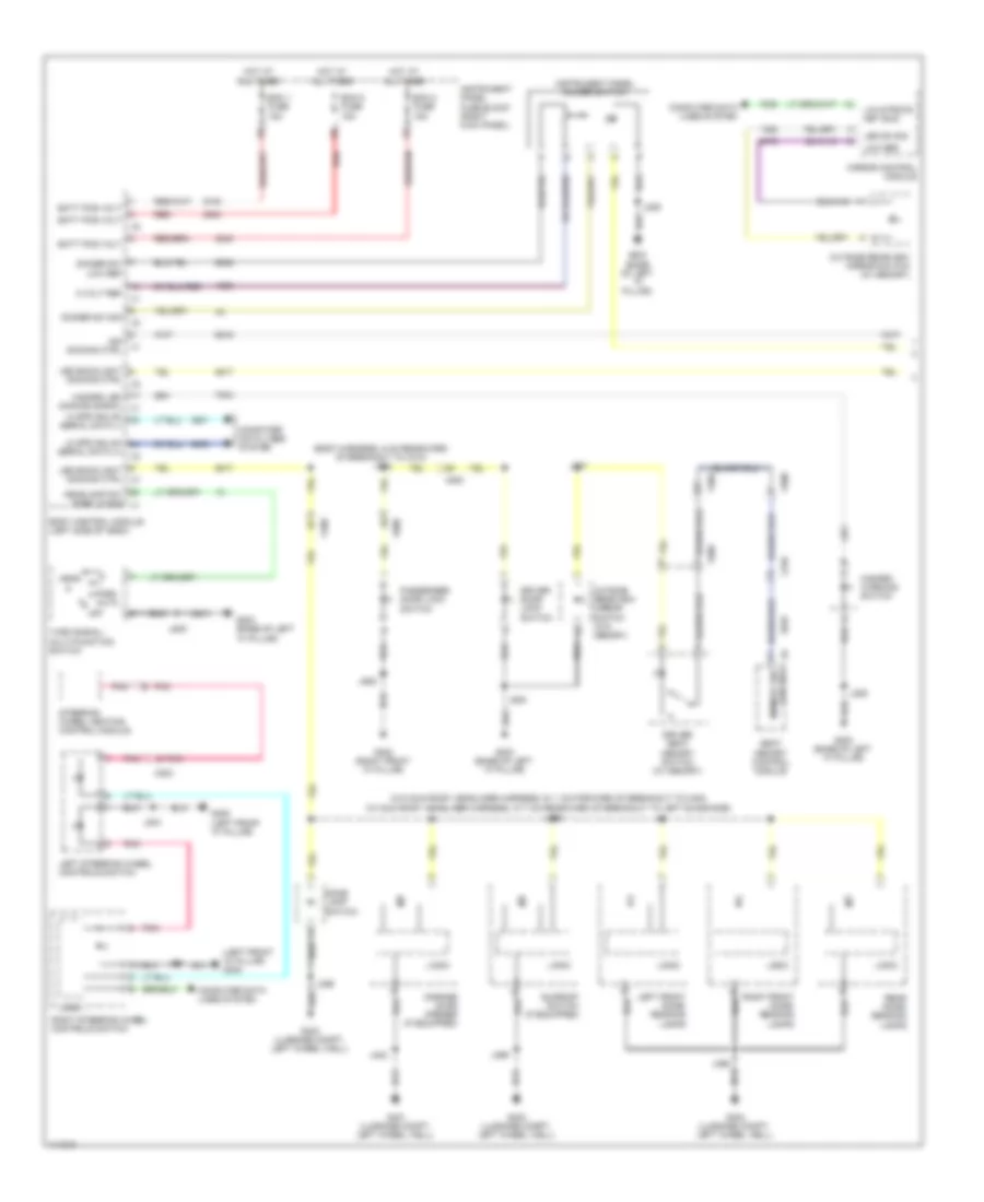
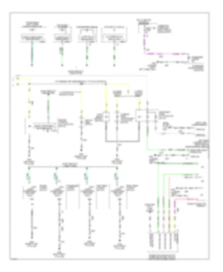
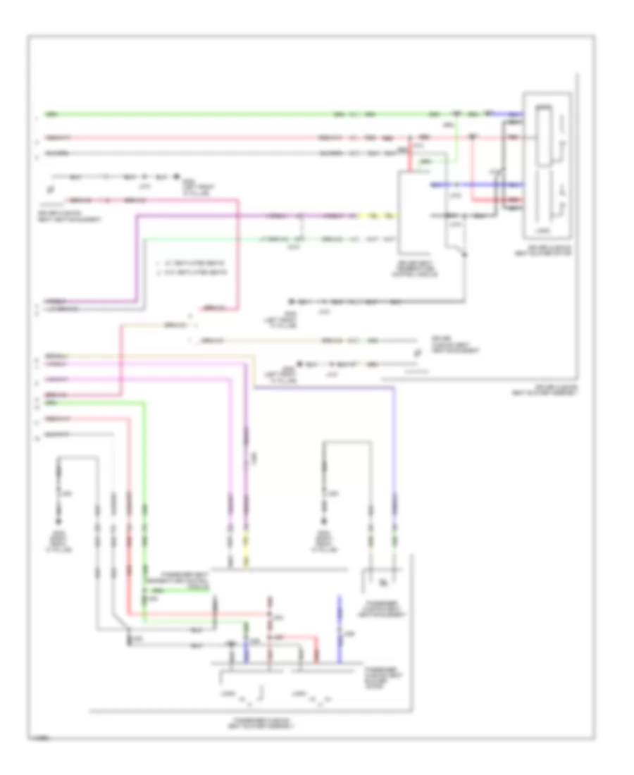
Body Control Modules Wiring Diagram (2 of 2) for Chevrolet Impala LT 2014
List of elements for Body Control Modules Wiring Diagram (2 of 2) for Chevrolet Impala LT 2014:
- (or 7538)
- (or 7539)
- Accessory wakeup ser data
- Anti-theft & door locks systems
- Backup lp sply volt
- Batt positive volt
- Batt rvc fuse 5a
- Battery
- Battery current sensor (on positive battery cable)
- Battery positive voltage
- Bcm 6 fuse 15a
- Bcm 7 fuse 10a
- Body control module (left side of dash)
- Child security lock motor
- Child security lock rly ctrl
- Closure handle sw open sig
- Computer data lines system
- Courtesy lamp sw sig
- Cruise/etc/tcc brake sig
- Current sens low ref
- Current sens sig
- Current sens sply volt
- Door locks & anti-theft systems
- Door locks & anti-theft systems interior lights system
- Door locks & anti-theft systems starting/charging system
- Dr lk actuator lk ctrl 2
- Dr lk actuator unlk ctrl
- Dr lk ctrl 2
- Driver door lock sw lock sig
- Driver door lock sw unlock
- Exterior lights system
- Frt windshield wiper sw hi sig
- G103 (left front engine compt frame rail)
- G305 (left front "a" pillar)
- Ground
- Hd lp lo beam relay ctrl
- Hdlp hi beam relay ctrl
- Headlights system
- Hi speed gmlan ser data (+)
- Hi speed gmlan ser data (-)
- Hood status b signal
- Horn relay ctrl
- Horns system
- Hot at all times
- Inadvertent pwr ctrl
- Instrument cluster system
- Instrument panel fuse block (right kick panel)
- Interior lights system
- Interior lp ctrl
- J229
- Key cap/clmn lk shift pos sig
- Led ambient lighting ctrl 1
- Led backlt dimming ctrl
- Left front drl sply voltage
- Left hdlp lo beam sply volt
- Lf park lp sply volt
- Lf turn sig lp sply volt
- Lift gate ajar sw sig
- Lift glass/trunk mtr rel ctrl
- Lin interconnect ntwrk bus 2
- Lin interconnect ntwrk bus 3
- Logistic mode relay close ctrl
- Logistic mode relay open ctrl
- Lr stop/turn lp sply volt
- Network bus 1
- Pass dr lk sw lk ctrl
- Pass dr lock sw unlock ctrl
- Power distribution system
- Puddle lamp sply voltage
- Rap relay coil control
- Rear license lp sply vol
- Rf turn sig lp sply volt
- Right hdlp lo beam sply volt right front drl sply voltage
- Right park lp sply volt
- Rr lk mtr status sig
- Rr turn sig lp sply volt
- Run relay coil ctrl
- Run/crank relay coil control
- Serial data comm enable
- Shift interlock sol ctrl
- Shift interlock system
- Starting/charging system
- Stop lp rly coil sply volt
- Trunk lp ctrl
- Trunk, tailgate, fuel doors system
- Trunk, tailgate, fuel doors system cruise control system
- Underhood fuse block (right side of engine compt)
- W/ hid
- W/o hid
- Windshield washer rly ctrl
- Wiper mtr park sw sig
- Wiper mtr rly coil sply vol
- Wiper/washer system
- X210
COMPUTER DATA LINES
Computer Data Lines Wiring Diagram (1 of 6) for Chevrolet Impala LT 2014
List of elements for Computer Data Lines Wiring Diagram (1 of 6) for Chevrolet Impala LT 2014:
- Acc wakeup ser data
- Battery energy control module
- Can bus hi 2 ser data
- Can bus hi ser data
- Can bus lo 2 ser data
- Can bus lo ser data
- Chassis control module (right rear luggage compt)
- Electronic brake control module (in brake pressure modulator valve)
- Engine control module (inside air cleaner assembly)
- Except hybrid
- Hi spd gmlan ser data (+) 1
- Hi spd gmlan ser data (+) 2
- Hi spd gmlan ser data (+) 3
- Hi spd gmlan ser data (-) 1
- Hi spd gmlan ser data (-) 2
- Hi spd gmlan ser data (-) 3
- Hybrid
- Hybrid/ev battery pack (hybrid) (in hybrid/ ev battery pack, rear left)
- J333 (body harness, 14 cm forward of breakout to x700)
- Lo spd gmlan ser data
- Ser data comm enable
- Starter/generator control module
- Telematics communication interface control module (w/ onstar) (top of rear window shelf)
- W/ onstar
- W/o onstar
- X115
- X220
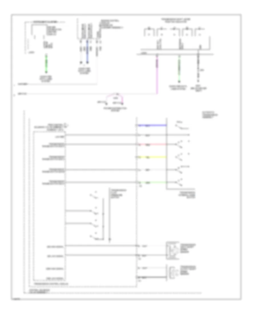
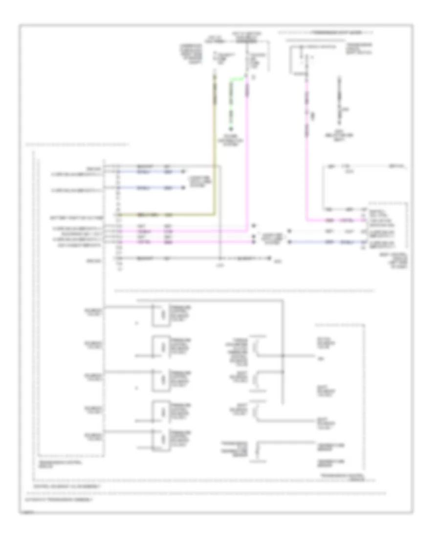
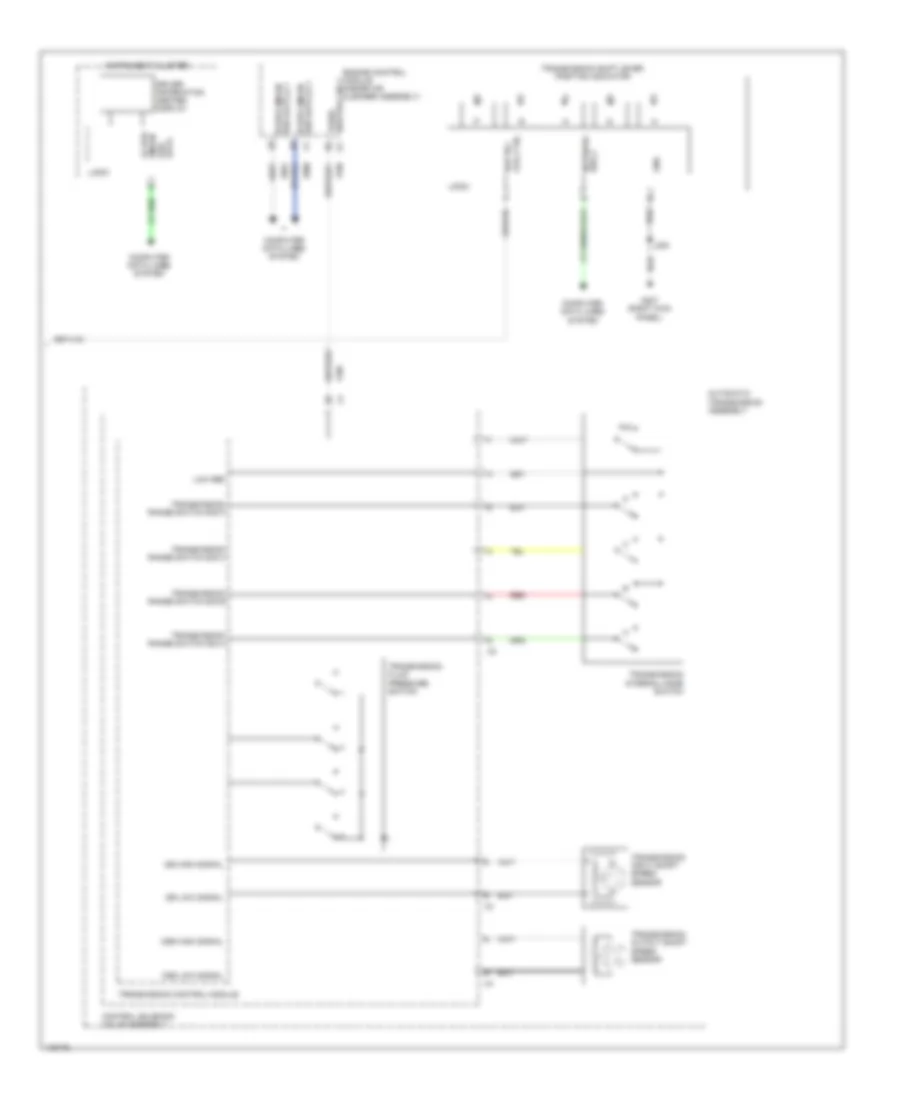
Computer Data Lines Wiring Diagram (2 of 6) for Chevrolet Impala LT 2014
List of elements for Computer Data Lines Wiring Diagram (2 of 6) for Chevrolet Impala LT 2014:
- (3.6l: engine harness, 18.1 cm from breakout to x115) (2.5l: engine harness, engine control module & x115, 6.5 cm from main bundle) (2.4l: engine harness, 6.7 cm from breakout to x115) j104
- (body harness, 4 cm from x500 to body control module)
- 2.4l & 2.5l
- 3.6l
- Automatic transmission assembly
- Bcm 1 fuse 15a
- Control solenoid valve assembly
- Dlc fuse 7.5a
- Except hybrid
- Except hybrid w/ adaptive cruise control
- Hi spd gmlan ser data (+) 1
- Hi spd gmlan ser data (+) 2
- Hi spd gmlan ser data (-) 1
- Hi spd gmlan ser data (-) 2
- Hot at all times
- Hybrid
- Instrument panel fuse block (right kick panel)
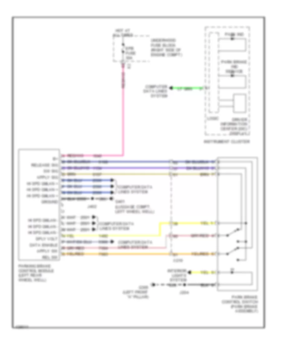
- J231
- Parking brake control module (left rear wheelwell)
- Power steering control module (mounted to steering gear)
- Ser data (+) 1 hi spd gmlan
- Ser data (-) 1 hi spd gmlan
- Ser data comm enable
- Serial data acc wakeup
- W/ adaptive cruise control
- W/ belt drive
- W/o belt drive
- X115
Computer Data Lines Wiring Diagram (3 of 6) for Chevrolet Impala LT 2014
List of elements for Computer Data Lines Wiring Diagram (3 of 6) for Chevrolet Impala LT 2014:
- Batt rvc fuse 5a
- Distance sensing cruise control module (w/ adaptive cruise control) (behind upper grille opening)
- Hi spd gmlan ser data (+) 1
- Hi spd gmlan ser data (+) 2
- Hi spd gmlan ser data (-) 1
- Hi spd gmlan ser data (-) 1 ser data comm enable
- Hi spd gmlan ser data (-) 2
- Hot at all times
- Human machine interface control module (w/o infotainment system) (front right instrument panel)
- Most control
- Most serial data (+)
- Most serial data (-)
- Network bus 5
- Ser data comm enable
- Underhood fuse block (right side of engine compt)
- W/ adaptive cruise control
- W/ infotainment system
- W/o adaptive cruise control
- W/o infotainment system
- X150
- X210
Computer Data Lines Wiring Diagram (4 of 6) for Chevrolet Impala LT 2014
List of elements for Computer Data Lines Wiring Diagram (4 of 6) for Chevrolet Impala LT 2014:
- (body harness, 19.2 cm forward of breakout to x700) j334
- Acc wakeup ser data
- Batt positive volt
- Body control module (left side of dash)
- Center console multifunction switch (w/ heated seats)
- Compass module (if equipped) (top of rear window shelf)
- Data link connector (left side of dash)
- Driver window motor
- Driver window switch
- Except hybrid
- Front seat heating control module (if equipped)
- G203 (base of left "a" pillar)
- G305 (left front "a" pillar)
- Hi spd gmlan ser data (+) 1
- Hi spd gmlan ser data (+) 2
- Hi spd gmlan ser data (-) 1
- Hi spd gmlan ser data (-) 2
- Hybrid
- Immobilizer control module (w/ keyless start: inside center console) (w/o keyless start: within steering column)
- J204
- J209
- J326 (seat temperature control module- passenger, in the passenger seat cushion vent mat)
- J337 (w/ heated seats) (body harness, 10 cm rearward of breakout to x700)
- J392 (sunroof harness, above headliner)
- Left rear window switch
- Lo spd gmlan ser data
- Logic
- Network bus 1
- Network bus 11
- Network bus 2
- Network bus 3
- Network bus 4
- Right rear window switch
- Ser data comm enable
- Steering wheel angle sensor (base of steering column)
- Sunroof motor (if equipped) (front center of sunroof module)
- Sunroof sunshade motor module (if equipped)
- Transmission shift lever position indicator
- W/ belt drive
- W/ keyless engine start switch
- W/o belt drive
- X115
- X210
- X300
- X320
- X390
- X500
- X505
- X700
- X800
Computer Data Lines Wiring Diagram (5 of 6) for Chevrolet Impala LT 2014
List of elements for Computer Data Lines Wiring Diagram (5 of 6) for Chevrolet Impala LT 2014:
- (body harness, 10 cm rearward of breakout to x320) (w/ memory) j343
- (i/p harness, 7.9 cm from breakout to media disc player) j206
- (not used)
- (w/ tilt & telescopic)
- Hvac control module
- Hvac controls
- Inflatable restraint sensing & diagnostic module
- Info display module
- Jx200
- Lo spd gmlan ser data
- Lo spd gmlan serial data
- Logic
- Mirror control module
- Most control
- Most serial data (+)
- Most serial data (-)
- Network bus 10
- Network bus 10 lo spd gmlan serial data
- Network bus 3
- Network bus 5
- Network bus 8
- Network bus 9
- Network bus 9 lo spd gmlan serial data
- Passenger window switch
- Radio
- Seat memory control module (w/ memory)
- Ser data comm enable
- Steering column position control module
- W/ infotainment system
- W/o infotainment system
- X210
- X310
- X500
- X505
- X600
- X605
Computer Data Lines Wiring Diagram (6 of 6) for Chevrolet Impala LT 2014
List of elements for Computer Data Lines Wiring Diagram (6 of 6) for Chevrolet Impala LT 2014:
- (not used)
- Audio amplifier (center front of trunk)
- Frontview camera module (w/ forward collision alert & lane departure warning sensor indicators)
- Instrument cluster
- Jx300
- Keyless entry control module (w/ keyless engine start switch & remote keyless entry) (right a-pillar)
- Left side object sensor module
- Lo spd gmlan
- Lo spd gmlan ser data
- Lo spd gmlan serial data
- Media disc player
- Most control
- Most ser data (+)
- Most ser data (-)
- Most serial data (+)
- Most serial data (-)
- Network bus 12
- Passenger presence module (passenger seat cushion)
- Rear parking assist control module (w/ rear parking assist sensor indicator) (left rear luggage compt)
- Right side object
- Right steering wheel controls switch
- Sensor module
- Serial data
- Steering wheel air bag coil
- W/ rear cross traffic alert & side obstacle detection sensor indicators
- X202
- X210
- X220
- X310
- X320
- X415
- X495
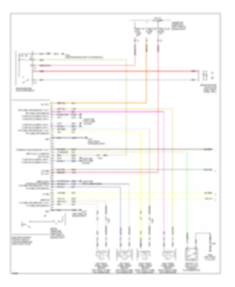
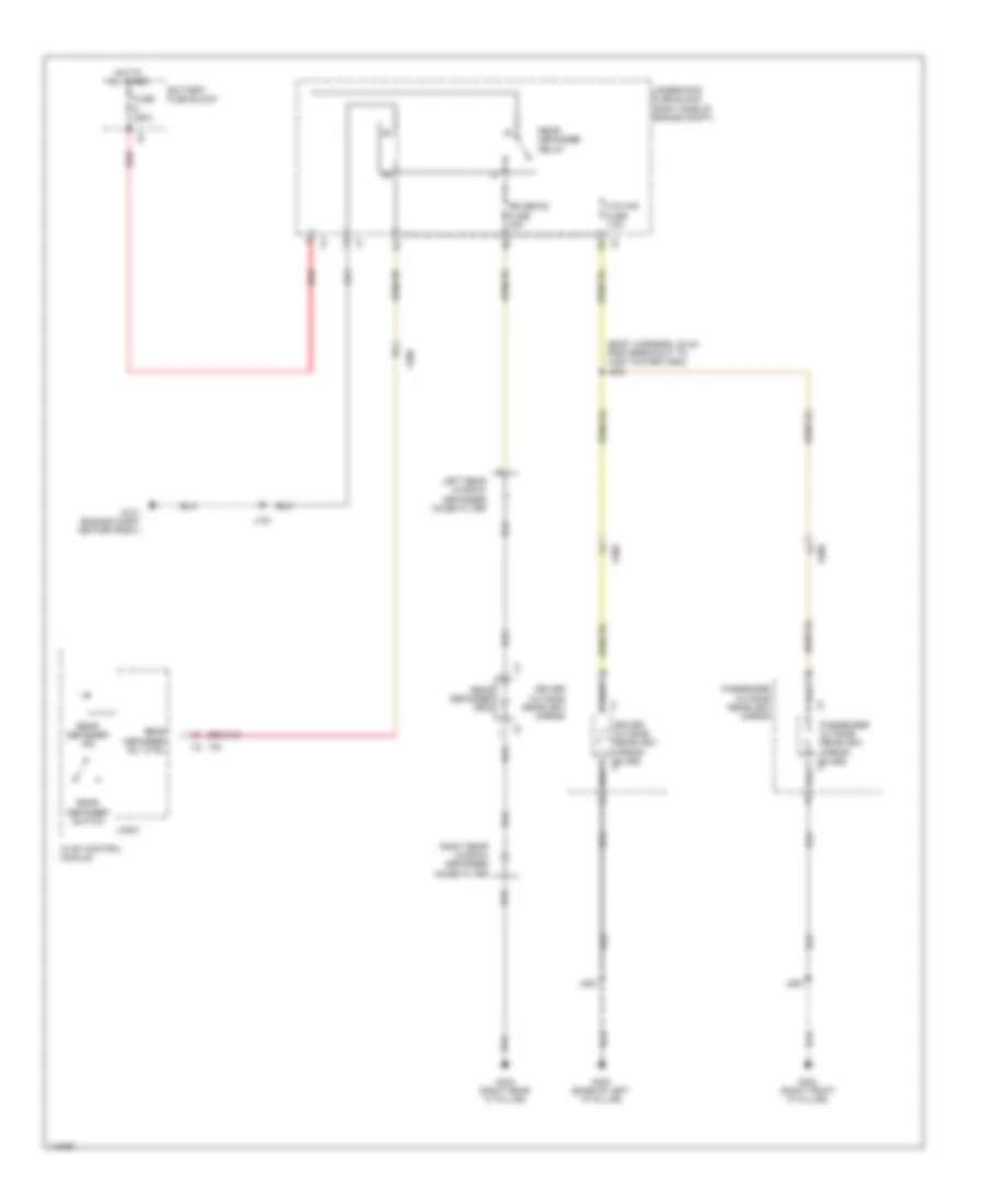
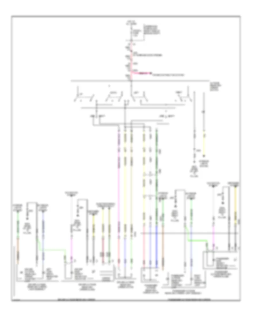
COOLING FAN
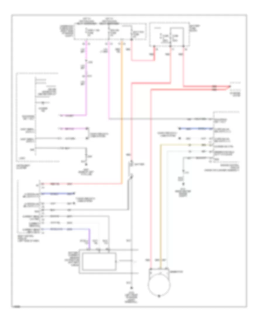
Cooling Fan Wiring Diagram for Chevrolet Impala LT 2014
List of elements for Cooling Fan Wiring Diagram for Chevrolet Impala LT 2014:
- (not used)
- 2.4l
- 87a
- Batt posi volt
- Battery fuse block
- Computer data lines system
- Cool fan hi fuse 40a
- Cool fan lo fuse 40a
- Cool temp sens lo
- Cooling fan high speed relay
- Cooling fan low speed relay
- Cooling fan speed control relay
- Ecm batt fuse 5a
- Eng coolant temp sens sig
- Engine control module (inside air cleaner assembly)
- Engine controls ignition relay
- Engine coolant temperature gauge
- Engine coolant temperature sensor (3.6l: left rear of left cylinder head) (2.4l: right rear side of engine) (2.5l: rear top of engine)
- Except 2.4l
- Fan rly a fuse 10a
- Fuse 250a
- G101 (center front engine compt)
- G106 (center engine compt on frame rail)
- G121 (rear center engine compt)
- Gnd
- Hi spd cooling fan rly ctrl
- Hi spd gmlan serial data (+) 1
- Hi spd gmlan serial data (-) 1
- Hot at all times
- Instrument cluster
- J101
- J121
- J150 (forward lamp harness, 5.8 cm from breakout to washer fluid container)
- Left cooling fan motor (behind left side of radiator)
- Lo spd cooling fan rly ctrl
- Logic
- Most serial data (+)
- Most serial data (-)
- Red
- Right cooling fan motor (behind right side of radiator)
- Underhood fuse block (right side of engine compt)
- X116
Hybrid Cooling Fan Wiring Diagram for Chevrolet Impala LT 2014
List of elements for Hybrid Cooling Fan Wiring Diagram for Chevrolet Impala LT 2014:
- Batt pos volt
- Batt posit volt
- Battery energy control module
- Battery fuse block
- Can bus high 2 serial data
- Can bus low 2 serial data
- Computer data lines system
- Coolant pump rly coil ctrl
- Coolant temp sens sig
- Engine control ignition relay
- Fan spd sig (1)
- Fan spd sig (2)
- Fuse 250a
- Fuse 7.5a
- G122 (above camshaft position exhaust sensor)
- G401 (luggage compt, left wheel well)
- Ground
- Hi spd gmlan serial data (+)
- Hi spd gmlan serial data (-)
- Hot at all times
- Hybrid/ev battery pack (luggage compt, behind rear seats)
- Hybrid/ev battery pack cooling fan (right side luggage compt)
- Hybrid/ev battery section 1
- Hybrid/ev battery section 2
- Hybrid/ev battery temperature sensor 1
- Hybrid/ev battery temperature sensor 2
- Hybrid/ev battery temperature sensor 3
- Hybrid/ev battery temperature sensor 4
- Hybrid/ev battery temperature sensor 5
- Hybrid/ev battery temperature sensor 6
- Hybrid/ev powertrain control module
- Inlet hybrid/ ev battery air pack temperature sensor
- J120
- J400
- J402
- Logic
- Low reference
- Mgu cool pmp fuse 10a
- Power pack fuse 15a
- Red
- Sens low ref
- Sig
- Starter/ generator coolant pump (on radiator fan assembly)
- Starter/ generator coolant pump relay
- Starter/ generator coolant temperature sensor (on radiator fan assembly)
- Starter/generator control module
- Underhood fuse block (left front of engine compt)
- Wakeup ser data
- X115
- X150
CRUISE CONTROL
Cruise Control Wiring Diagram (1 of 2) for Chevrolet Impala LT 2014
List of elements for Cruise Control Wiring Diagram (1 of 2) for Chevrolet Impala LT 2014:
- 5 volt ref
- 5 volt ref (1)
- 5 volt reference
- 5 volt reference (2)
- Acc pedal pos lo ref (1)
- Acc pedal pos lo ref (2)
- Acc pedal pos sig (2)
- Acc pedal position sig (1)
- Accelerator pedal position sensor (app) (top of accelerator pedal assembly)
- Batt rcv fuse 5a
- Battery positive volt
- Body control module (bcm) (left side of dash)
- Brk position sens lo ref
- Brk position sens sig
- Computer data lines system
- Cruise control sw sig
- Cruise ind
- Cruise/etc/tcc brk sig
- Driver information center display
- Ecm batt fuse 5a
- Engine control module (ecm) (inside air cleaner assembly)
- G121 (hybrid: front center engine compt) (except hybrid: rear center engine compt)
- Hi speed gmlan serial data (+) 1
- Hi speed gmlan serial data (-) 1
- Hot at all times
- Instrument panel cluster (ipc)
- J121
- Lighting ctrl sw ref
- Lo speed gmlan serial data
- Logic
- Serial data (+) 1 hi speed gmlan serial data (-) 1
- Signal ground
- Throttle act ctrl close
- Throttle act ctrl open
- Throttle body (front of intake manifold)
- Throttle post sens lo ref
- Throttle post sens sig (1)
- Underhood fuse block (right side of engine compt)
- Up/down switch signal
- X115
- X210
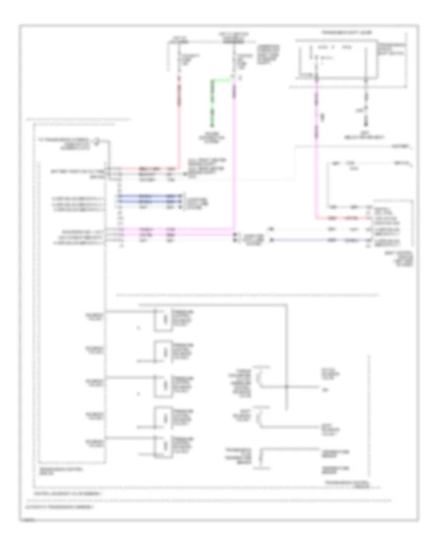
Cruise Control Wiring Diagram (2 of 2) for Chevrolet Impala LT 2014
List of elements for Cruise Control Wiring Diagram (2 of 2) for Chevrolet Impala LT 2014:
- 2.5l & 2.4l hybrid
- 3.6l
- Acc fuse 10a
- Automatic transmission assembly
- Batt pos volt
- Brake pedal position sensor (top of brake pedal assembly)
- Cancel
- Computer data lines system
- Comu enable serial data
- Control solenoid valve assembly
- Cruise switch (w/o adaptive cruise control) adaptive cruise switch (w/ adaptive cruise control)
- Distance sensing cruise control module (behind upper grille opening)
- Except hybrid
- G101 (engine compt center front)
- Gap switch (w/o adaptive cruise control) forward collision alert sensor (w/ adaptive cruise control)
- Gnd
- Hot at all times
- Hybrid
- Hybrid/ev battery pack (luggage compartment, behind rear seats)
- Hybrid/ev powertrain control module
- J101
- Left steering wheel controls switch
- Res+
- Serial data (+) 1 hi speed gmlan
- Serial data (+) 2 hi speed gmlan
- Serial data (-) 1 hi speed gmlan
- Serial data (-) 2 hi speed gmlan
- Set-
- Starter/generator control module
- Steering wheel air bag coil
- Transmission control module (tcm)
- Transmission input shaft speed sensor
- Transmission output shaft speed sensor
- Underhood fuse block (right side of engine compt)
- X150
- X202
- X210
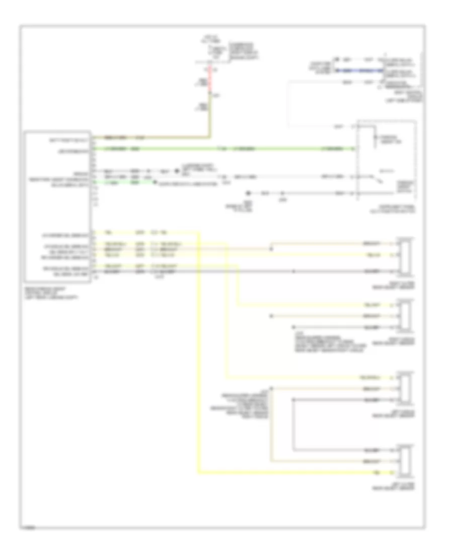
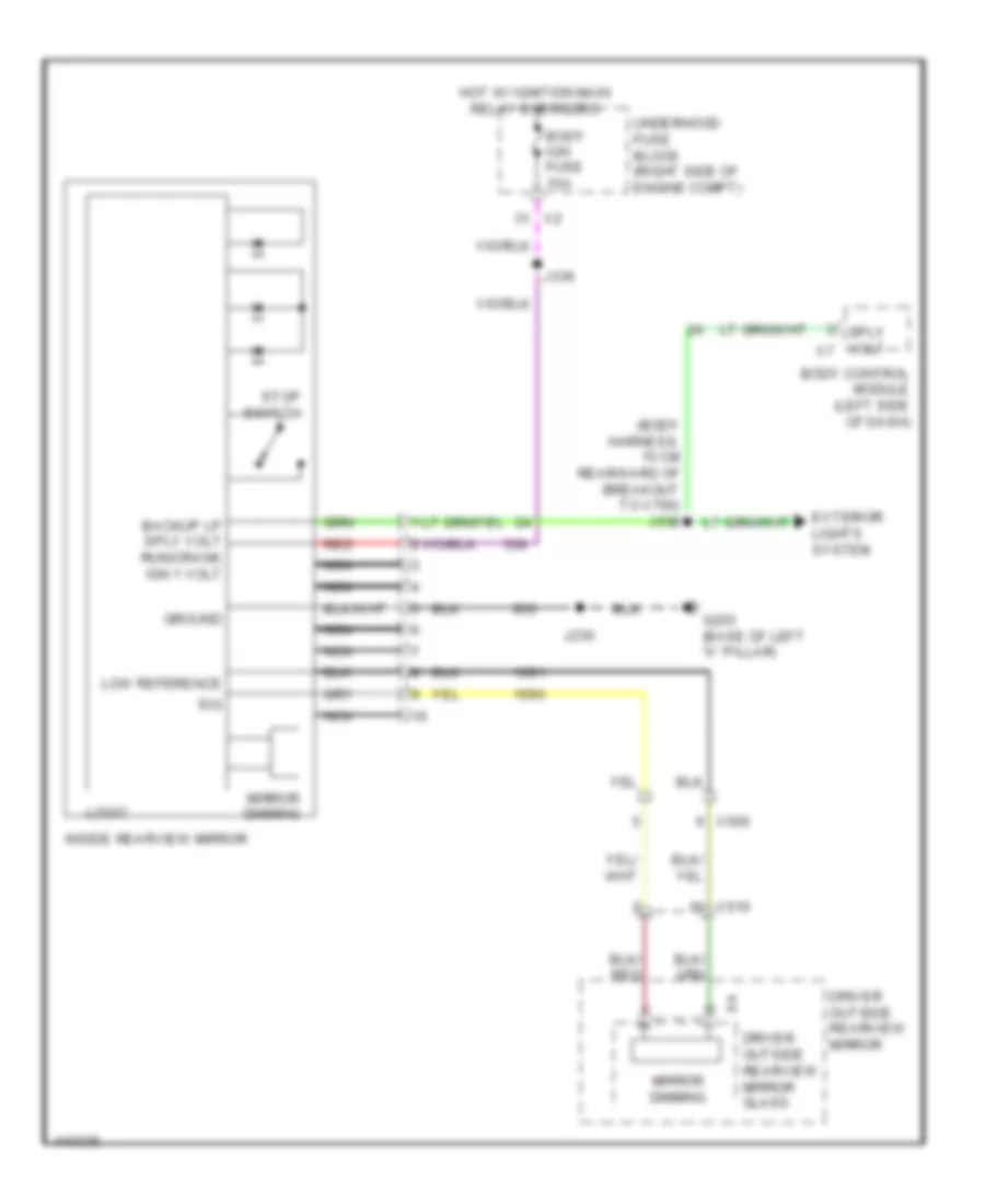
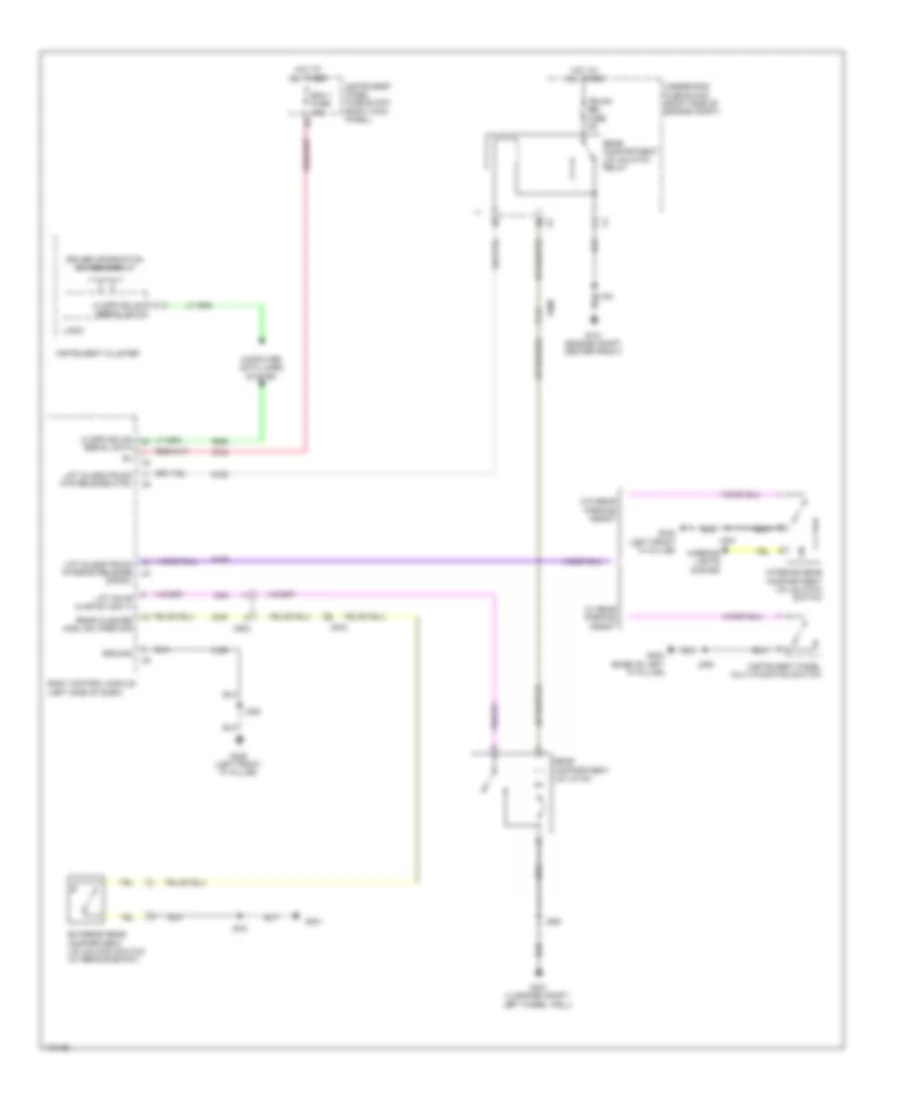
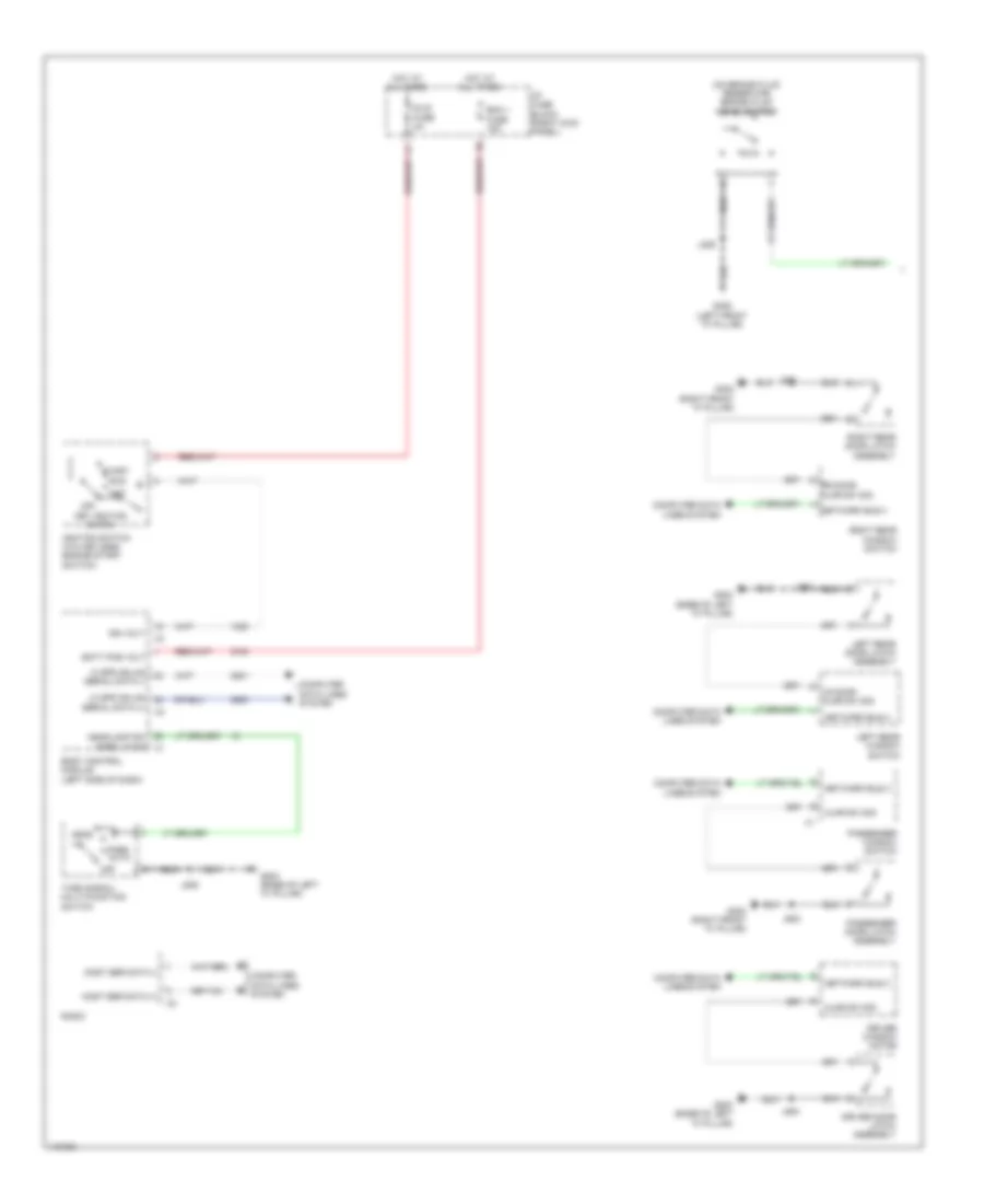
DEFOGGERS
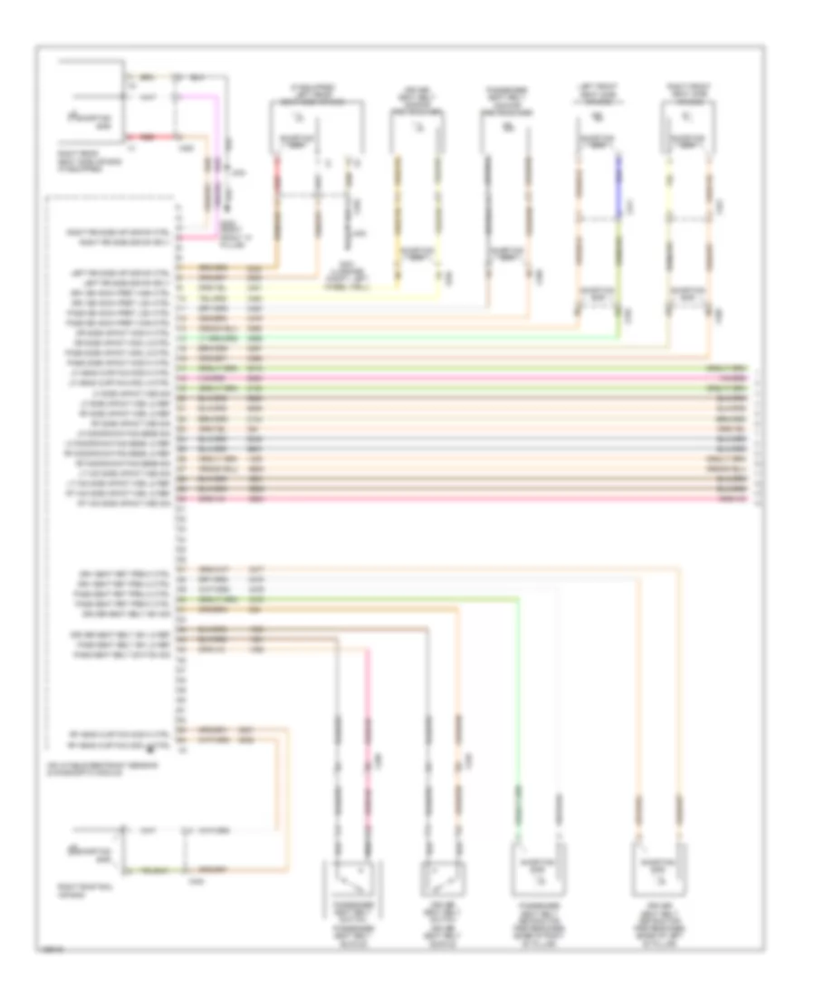
Defoggers Wiring Diagram for Chevrolet Impala LT 2014
List of elements for Defoggers Wiring Diagram for Chevrolet Impala LT 2014:
- (body harness, 22 cm from breakout to x220 toward x600) j233
- Battery fuse block
- Driver outside rearview mirror
- Driver outside rearview mirror glass
- Fuse 250a
- G101 (engine compt center front)
- G203 (base of left "a" pillar)
- G302 (right front "a" pillar)
- G404 (right rear "c" pillar)
- Hot at all times
- Htd mir fuse 7.5a
- Hvac control module
- J100
- J500
- J600
- Left rear window defogger noise filter
- Logic
- Passenger outside rearview mirror
- Passenger outside rearview mirror glass
- Rear defogger grid
- Rear defogger ind
- Rear defogger relay
- Rear defogger rly ctrl
- Rear defogger switch
- Red
- Right rear window defogger noise filter
- Rr defog fuse 40a
- Underhood fuse block (right side of engine compt)
- X200
- X500
- X600
ELECTRONIC POWER STEERING
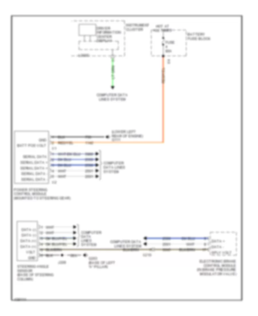
Electronic Power Steering Wiring Diagram, with Belt Drive for Chevrolet Impala LT 2014
List of elements for Electronic Power Steering Wiring Diagram, with Belt Drive for Chevrolet Impala LT 2014:
- Batt pos volt
- Battery fuse block
- Computer data lines system
- Data (+)
- Data (-)
- Data +
- Data -
- Driver information center display
- Electronic brake control module (in brake pressure modulator valve)
- Fuse 100a
- G111 (lower left rear of engine)
- G203 (base of left "a" pillar)
- Gnd
- Hot at all times
- Instrument cluster
- J209
- Logic
- Power steering control module (mounted to steering gear)
- Serial data
- Serial data +
- Serial data -
- Sply volt
- Steering angle sensor (base of steering column)
- Volt
- X210
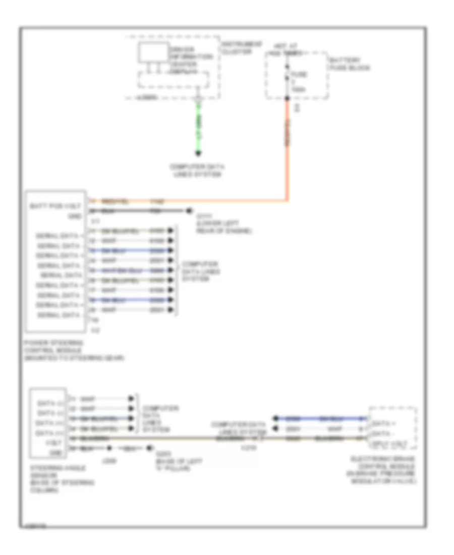
Electronic Power Steering Wiring Diagram, without Belt Drive for Chevrolet Impala LT 2014
List of elements for Electronic Power Steering Wiring Diagram, without Belt Drive for Chevrolet Impala LT 2014:
- (lower left rear of engine) g111
- Batt pos volt
- Battery fuse block
- Computer data lines system
- Data (+)
- Data (-)
- Data +
- Data -
- Driver information center display
- Electronic brake control module (in brake pressure modulator valve)
- Fuse 80a
- G203 (base of left "a" pillar)
- Gnd
- Hot at all times
- Instrument cluster
- J209
- Logic
- Power steering control module (mounted to steering gear)
- Serial data
- Serial data +
- Serial data -
- Sply volt
- Steering angle sensor (base of steering column)
- Volt
- X210
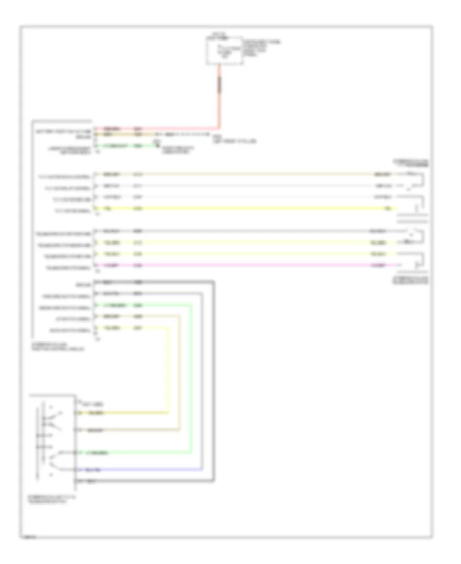
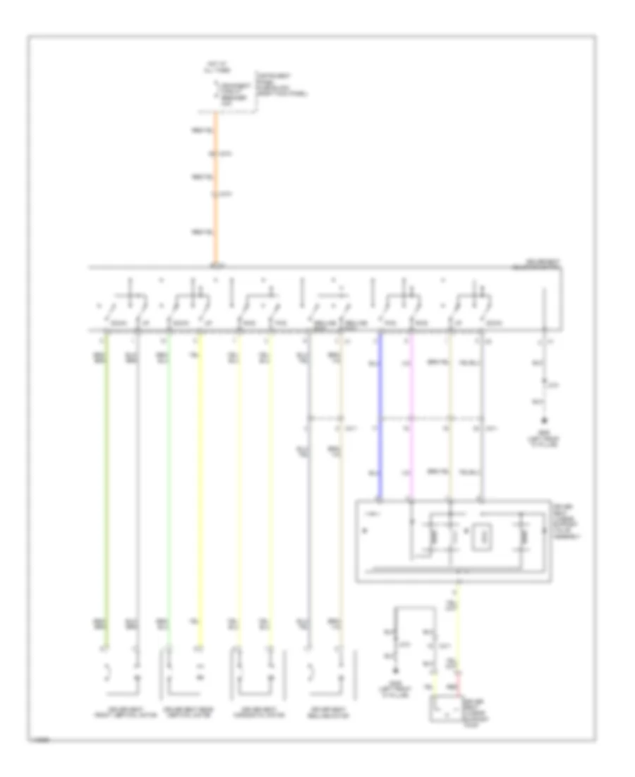
Power Tilt Steering Column Wiring Diagram for Chevrolet Impala LT 2014
List of elements for Power Tilt Steering Column Wiring Diagram for Chevrolet Impala LT 2014:
- Battery positive voltage
- Computer data lines system
- Down switch signal
- E (not used)
- Forward switch signal
- G305 (left front "a" pillar)
- Ground
- Hot at all times
- Instrument panel fuse block (right kick panel)
- J204
- Linear interconnect network bus 8
- Rearward switch signal
- Steering column position control module
- Steering column telescope motor
- Steering column tilt & telescope switch
- Steering column tilt motor
- Telescope motor forward
- Telescope mtr rearward
- Telescope mtr return
- Telescope mtr signal
- Tilt motor down control
- Tilt motor return
- Tilt motor signal
- Tilt motor up control
- Tilt/tele fuse 15a
- Up switch signal
ENGINE PERFORMANCE
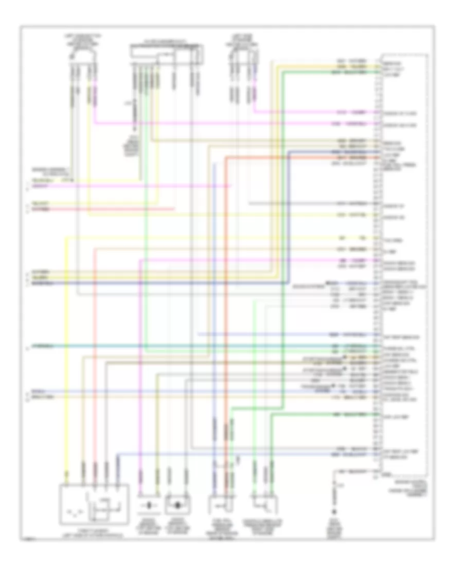
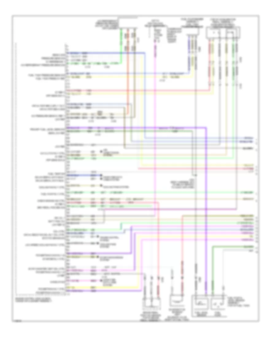
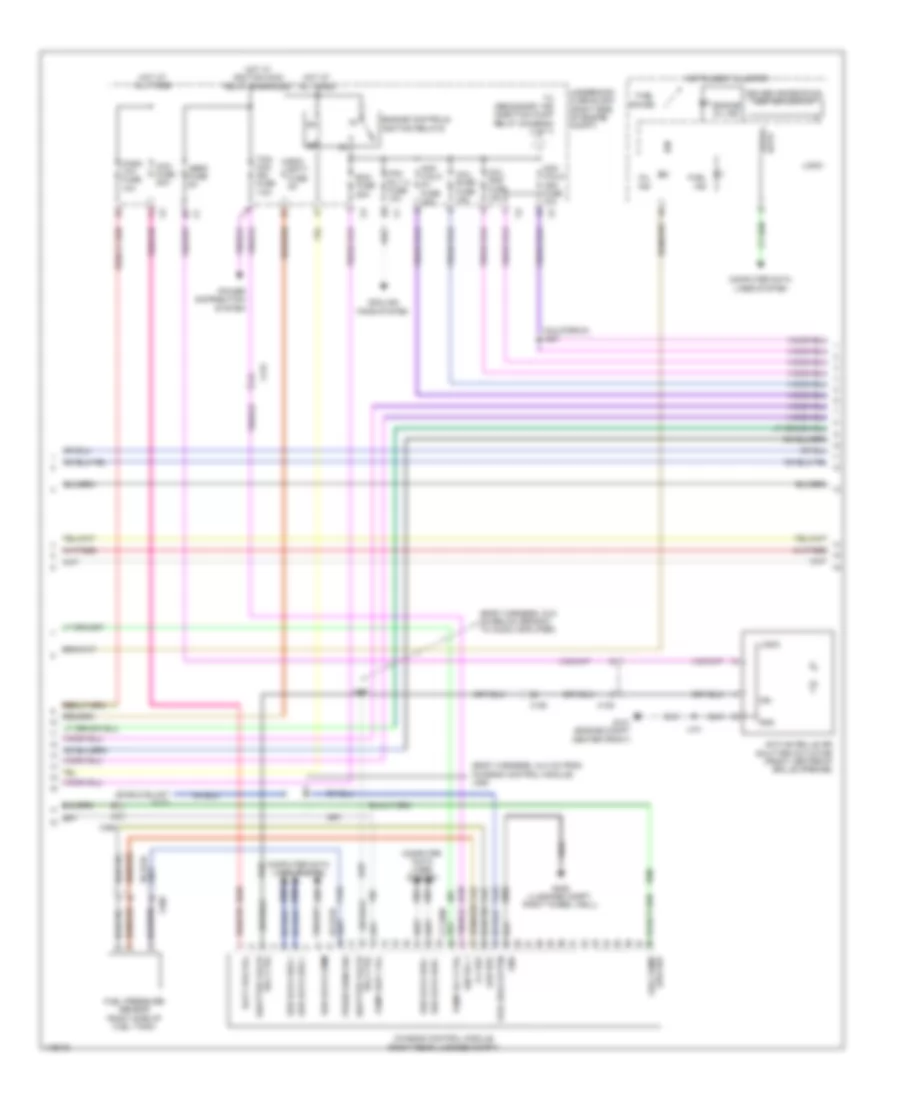
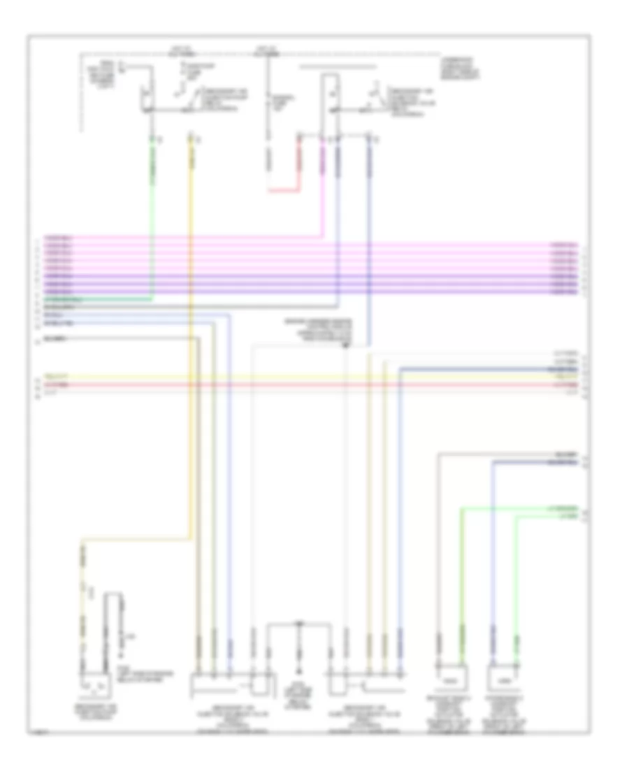
2.4L VIN R
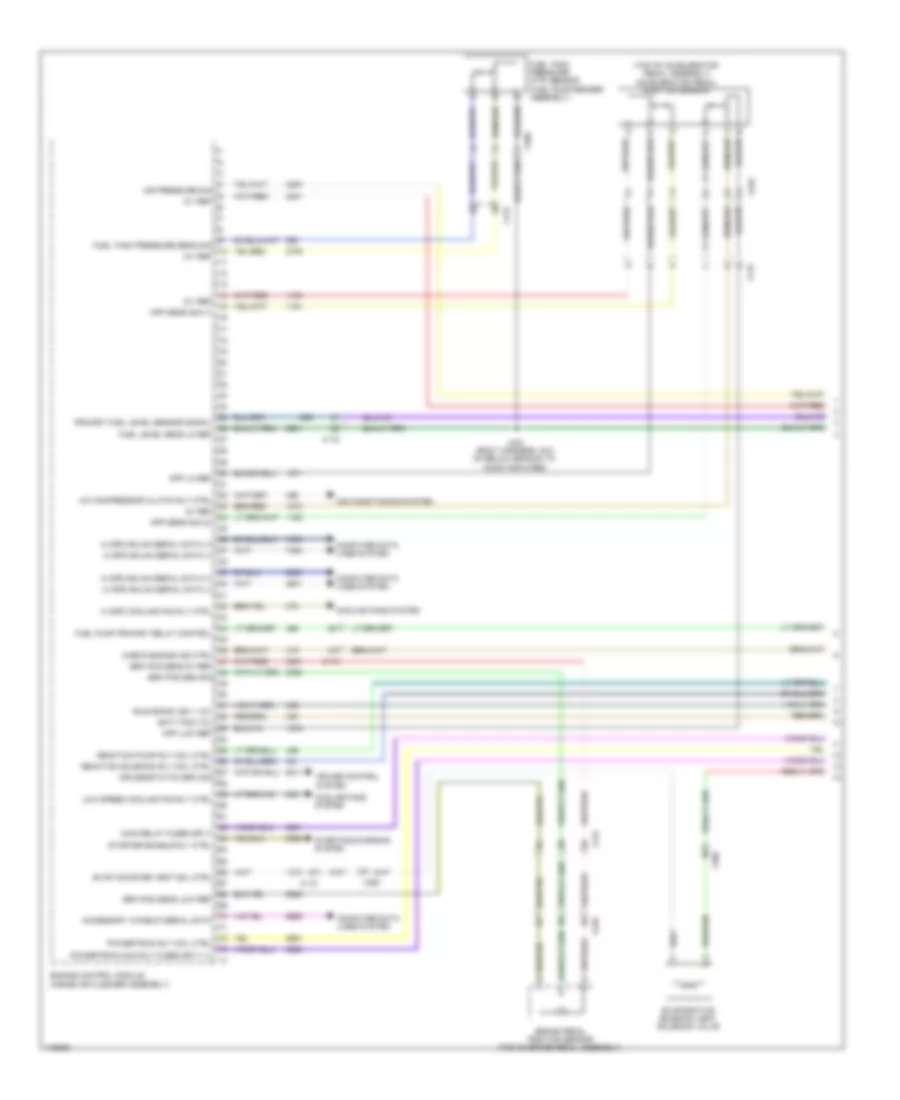
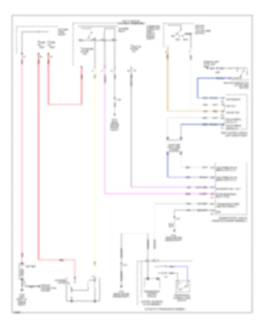
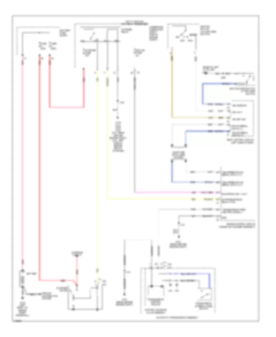
2.4L VIN R, Engine Controls Wiring Diagram (1 of 5) for Chevrolet Impala LT 2014
List of elements for 2.4L VIN R, Engine Controls Wiring Diagram (1 of 5) for Chevrolet Impala LT 2014:
- (body harness, 28.5 cm below branch to audio amplifier) j434
- (fuel pump/ sender assembly) fuel tank pressure sensor
- (on a/c line, under air cleaner) a/c refrigerant pressure sensor
- (right side of engine compt) underhood fuse block
- 5v ref
- 5v ref 1
- 5v ref 3
- 5v ref 4
- A/c sens sig
- Accelerator pedal position sensor (top of accelerator pedal assembly)
- Air conditioning system
- App sens sig 1
- App sig
- Check eng ind ctrl
- Cmpsr cltch
- Computer data lines system
- Cooling fans system
- Cruise control system
- Eng rly ctrl
- Engine control module (inside air cleaner assembly)
- Evaporative emission canister vent solenoid (right of fuel tank)
- Fan rly ctrl
- Fuel lvl sen sig
- Fuel lvl sens lo ref
- Fuel pres sens sig
- Fuel pump & level sensor assembly (top of fuel tank)
- Fuel pump rly ctrl
- Hi ser data bus (+)
- Hi ser data bus (-)
- Ign
- Ign 1 volt
- Low ref
- Pdl pos low ref
- Rly ctrl
- Sec air inj sol sig
- Solenoid ctrl
- Solenoid ctrl cruise/etc/tcc brake sig
- Starter rly ctrl
- Starting/charging system
- Wake-up ser data
- X115
- X117
- X210
- X350
2.4L VIN R, Engine Controls Wiring Diagram (2 of 5) for Chevrolet Impala LT 2014
List of elements for 2.4L VIN R, Engine Controls Wiring Diagram (2 of 5) for Chevrolet Impala LT 2014:
- (body harness, 23.5 cm below branch to audio amplifier) j433
- (body harness, 44.3 cm from
- (left side of engine) (california) secondary air injection pump
- (rear center engine compt) g122
- (right side of engine compt) underhood fuse block
- A/c compressor clutch relay
- Active grille air shutter actuator (front center of of grille opening)
- Aero fuse 5a
- Cann vent fuse 5a
- Ccm fuse 20a
- Chassis control module (right rear luggage compt)
- Chassis control module)
- Communication enable
- Computer data lines system
- Cooling fan high speed relay
- Driver information center (dic) display
- Ecm batt fuse 5a
- Ecm ign fuse 5a
- Flp sens 5v ref
- Fpp rly ctrl
- From engine control ignition relay (diagram 4 of 5)
- Fuel pressure sensor (right side of fuel tank)
- G101 (center front engine compt)
- G405 (luggage compt right wheel well)
- Gmlan serial data
- Gnd
- Ground
- Hot at all times
- Hot w/ ignition main relay energized
- Ign
- Ign 1 volt run/crank
- Ind ctrl
- Instrument cluster
- J101
- J120
- J455
- Logic
- Low ref
- Low ref flp sens
- Mal- function lamp ind
- Oil level ind
- Power distribution system
- Press sens sig
- Red
- Sair pump fuse 50a
- Sair sol fuse 15a
- Secondary air injection pump relay (california)
- Secondary air injection solenoid valve relay (california)
- Serial data (+)
- Serial data (-)
- Shield extension
- Shutter valve sol ctrl
- Sply volt fuel pump
- Tcm/ ccm ign fuse 7.5a
- X105
- X114
- X115
- X150
- X350
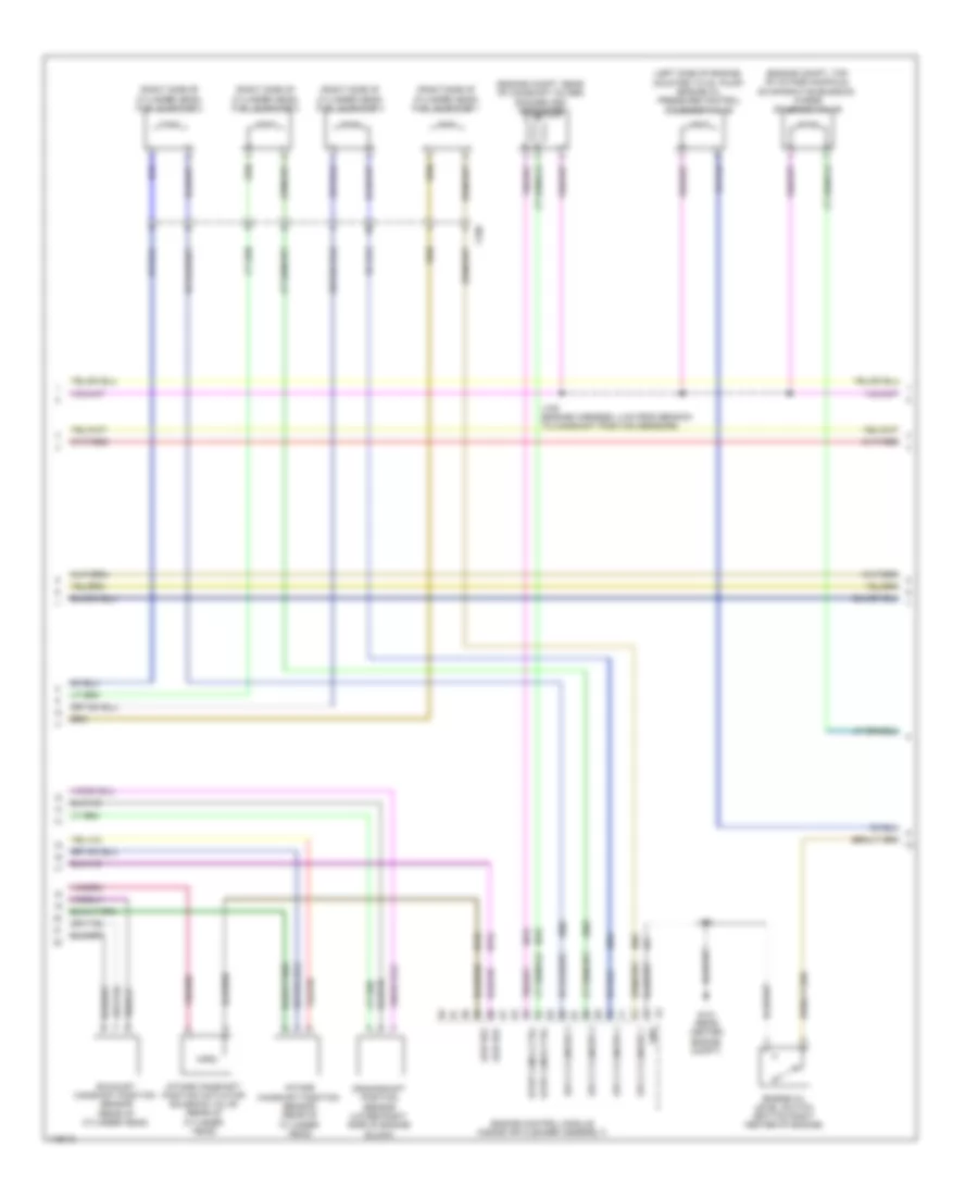
2.4L VIN R, Engine Controls Wiring Diagram (3 of 5) for Chevrolet Impala LT 2014
List of elements for 2.4L VIN R, Engine Controls Wiring Diagram (3 of 5) for Chevrolet Impala LT 2014:
- (engine harness, 5.2 cm from g122 toward evaporative emission purge solenoid valve)
- (left side of valve cover) ignition coil 1
- (left side of valve cover) ignition coil 2
- (left side of valve cover) ignition coil 3
- (left side of valve cover) ignition coil 4
- (right rear of engine) high pressure fuel pump
- 5v 1 ref
- 5v ref 2
- Cnrk pos sens sig
- Crankshaft position sensor (lower right side of engine block)
- Ect sens sig
- Engine control module (inside air cleaner assembly)
- Engine coolant temperature sensor (right rear side of engine)
- Engine oil pressure switch (rear top of engine)
- Exhaust bank 1 sig
- Exhaust camshaft position sensor (front of cylinder head)
- G122 (rear center engine compt)
- High ctrl
- Ic 1 ctrl
- Ic 2 ctrl
- Ic 3 ctrl
- Ic 4 ctrl
- Intake bank 1 sig
- Intake camshaft position sensor (front of cylinder head)
- J103
- J106 (engine harness, 16.9 cm from branch to rear of engine compt)
- J120
- J122
- Low ctrl
- Low ref
- Nca
- Oil pressure sw sig
- Secondary air injection solenoid valve cylinder 3/4
- Spark plug
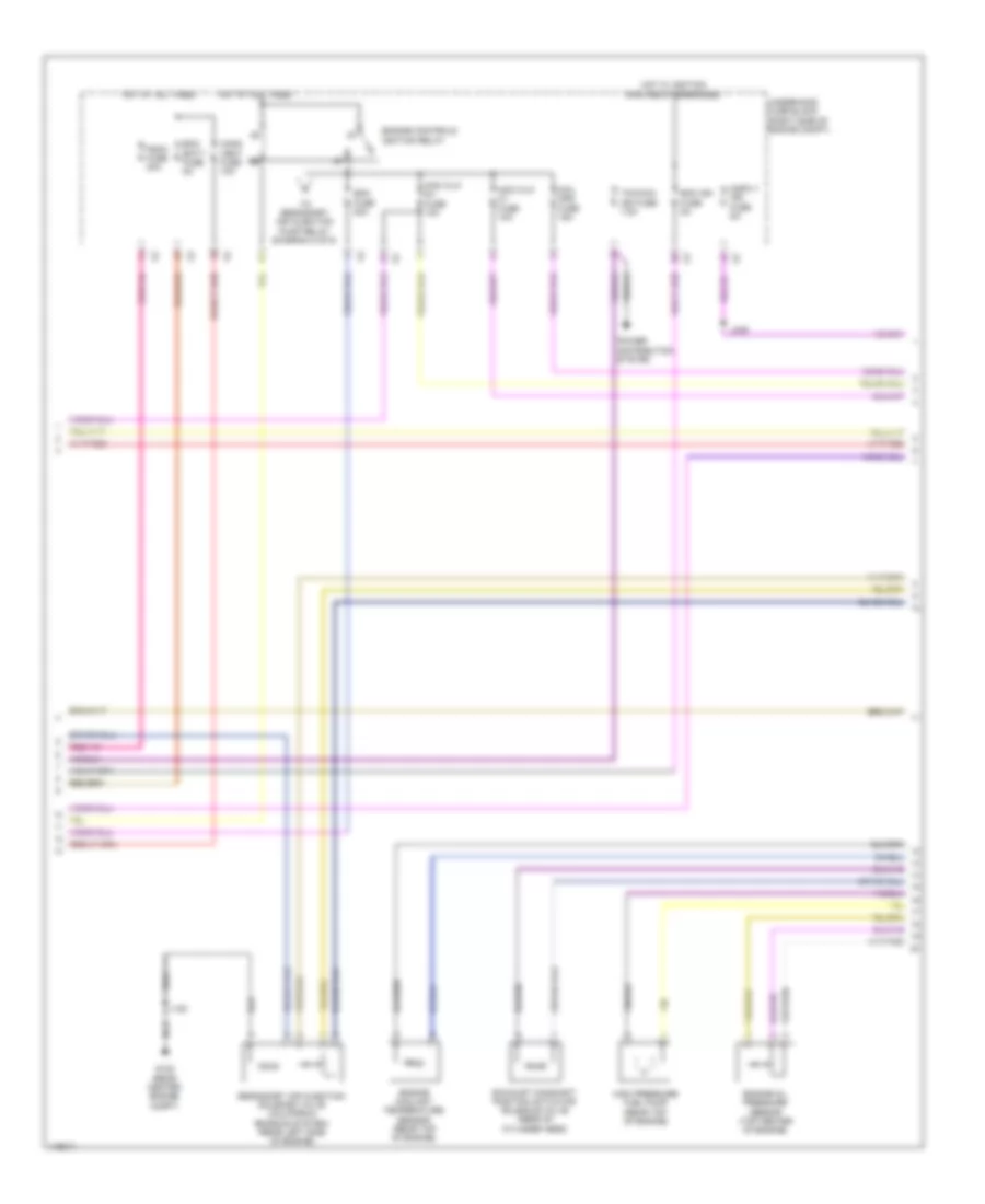
2.4L VIN R, Engine Controls Wiring Diagram (4 of 5) for Chevrolet Impala LT 2014
List of elements for 2.4L VIN R, Engine Controls Wiring Diagram (4 of 5) for Chevrolet Impala LT 2014:
- (left side of cylinder head)
- (right side of engine compt) underhood fuse block
- 5-volt ref 1
- Battery fuse block
- Coil odd fuse 15a
- Cooling fan low speed relay
- Ecm fuse 25a
- Engine control ignition relay
- Engine control module (inside air cleaner assembly)
- Exhaust camshaft position actuator solenoid valve (front of cylinder head)
- Exhaust solenoid (1)
- Fan rly a fuse 10a
- Fuel injector 1
- Fuel injector 1 ctrl
- Fuel injector 1 cynd
- Fuel injector 2
- Fuel injector 2 ctrl
- Fuel injector 2 cyl
- Fuel injector 3
- Fuel injector 3 ctrl
- Fuel injector 3 cyl
- Fuel injector 4
- Fuel injector 4 ctrl
- Fuel injector 4 cyl
- Fuse 250a
- G121 (front center engine compt)
- Hot at all times
- Intake camshaft position actuator solenoid valve (front of cylinder head)
- Intake solenoid (1)
- J108
- J121
- Low ref
- Non wlk pt fuse 10a
- Red
- Sig ground
- To a/c compressor clutch relay (diagram 2 of 5)
- X160
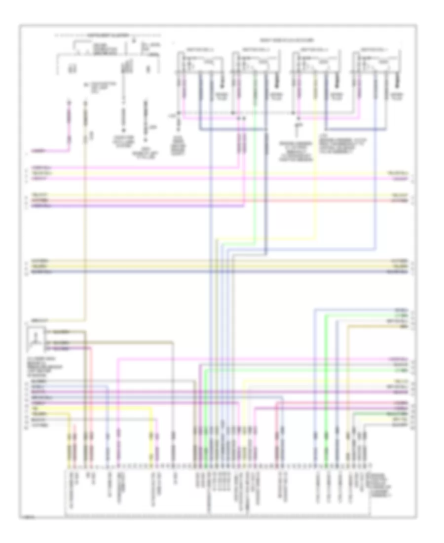
2.4L VIN R, Engine Controls Wiring Diagram (5 of 5) for Chevrolet Impala LT 2014
List of elements for 2.4L VIN R, Engine Controls Wiring Diagram (5 of 5) for Chevrolet Impala LT 2014:
- (california) secondary air injection solenoid valve cylinder 1/2
- (right side bottom of engine) heated oxygen sensor 2
- (right side of engine) heated oxygen sensor 1
- (top center of engine on fuel rail) fuel rail pressure sensor
- 5v ref 1
- 5v ref 3
- 5v ref 4
- Actuator ctrl close
- Actuator ctrl open
- Air press sens sig
- Air temp sens sig
- Charge ind ctrl
- Duty cycle sig
- Engine control module (inside air cleaner assembly)
- Evaporative emission purge solenoid valve (engine compt, mounted to left side of cylinder head)
- Frp sens sig
- G121 (front center engine compt)
- G122 (rear center engine compt)
- Ground
- Ho2s b1 s1
- Ho2s b1 s2
- J117 (engine harness, 11.9 cm from branch to rear of engine components)
- J120
- J121
- Knock sens low ref
- Knock sens sig
- Knock sensor
- Logic
- Low ref
- Low sig bank 1 sens (1)
- Low sig bank 2 sens (2)
- Maf low ref
- Maf sens sig
- Manifold absolute pressure sensor (left side of engine)
- Map low ref
- Map sens sig
- Mass air flow/intake air temperature sensor (mounted to upper air cleaner assembly)
- Nca
- Park/neutral sig
- Sens low ref
- Solenoid ctrl
- Sply volt
- Starting/charging system
- Throttle body (top of intake manifold)
- Tp sens sig
- Transmissions system
- X114
- X160
2.4L VIN R, Hybrid System Wiring Diagram (1 of 4) for Chevrolet Impala LT 2014
List of elements for 2.4L VIN R, Hybrid System Wiring Diagram (1 of 4) for Chevrolet Impala LT 2014:
- (engine harness, 4 cm from branch to engine control module to g122)
- (engine harness, 4 cm pnk from ignition coil 3 to ignition coil 2) j122
- (part of hood latch) hood ajar switch
- (top of brake pedal assembly) brake pedal position sensor
- Aux wkup serial data
- Auxiliary transmission fluid pump relay
- Bas pwr inverter fuse 175a
- Brake position snsr 5v ref
- Brk pos snsr low ref
- Brk pos snsr sig
- Computer data lines system
- Coolant pump relay coil control
- Driver motor control module 1
- G101 (engine compt center front)
- Hi volt interlock loop lo ref
- Hi volt interlock loop signal
- Hot at all times
- Hot w/ engine controls ignition relay energized
- Hybrid/ev battery pack (luggage compt, behind rear seats)
- Hybrid/ev powertrain control module
- J101
- J121 (engine harness, 11.2 cm from main bundle)
- J123
- J124
- J126
- J127
- J128
- J129
- Nca
- Pnk
- Red
- Resolver cosine signal drain wire
- Resolver motor drain wire
- Resolver mtr positive
- Resolver signal 1
- Resolver signal 2
- Resolver signal 3
- Resolver signal 4
- Resolver sine signal drain wire
- Starter/ generator cable cover
- Starter/generator
- Starter/generator control module
- Three phase motor temp drain wire
- Three phase motor temp low ref
- Three phase motor temp sig hood open sw sig
- Trans aux pmp fuse 30a
- Transmission auxiliary oil pump rly ctrl
- U phase
- Underhood fuse block (right side of engine compt)
- V phase
- W phase
- X10
- X115
- X150
- X210
2.4L VIN R, Hybrid System Wiring Diagram (2 of 4) for Chevrolet Impala LT 2014
List of elements for 2.4L VIN R, Hybrid System Wiring Diagram (2 of 4) for Chevrolet Impala LT 2014:
- (left side of dash) body control module
- (on transmission assembly) auxiliary transmission fluid pump
- 115v+
- 115v-
- Acc wakeup ser data
- Ajar sw sig
- Batt (+)
- Batt pos volt
- Batt positive volt
- Batt positive voltage
- Batt rvc fuse 5a
- Battery energy control module
- Bpim ign fuse 5a
- Computer data lines system
- Coolant temp snsr sig
- Current snsr low
- Current snsr sig
- Current snsr sply
- Fan spd sig 1
- Fan spd sig 2
- From hybrid/ev battery section 2 (diagram 4 of 4)
- G122 (right center engine compt)
- G203 (base of left "a" pillar)
- G401 (luggage compt, left wheel well)
- Gnd
- Ground
- Hi volt interlock loop sig 1
- High ser data
- High voltage relay
- Hot at all times
- Hot w/ engine controls ignition relay energized
- Hot w/ ignition main relay energized
- Hybrid/ev battery pack (luggage compt, behind rear seats)
- Hybrid/ev battery pack cable cover
- Hybrid/ev battery pack cooling fan (right side luggage compt)
- Hybrid/ev battery pack current sensor
- Hybrid/ev battery pre-charge resistor
- Hybrid/ev powertrain control module
- J120
- J209
- J400
- J402
- Logic
- Low ref
- Low ser data
- Main contactor
- Mgu cool pmp fuse 10a
- Nca
- Pnk
- Power pack blower fuse 15a
- Power pack fuse 7.5a
- Pre-charge contactor
- Precharge relay
- Red
- Reference
- Run/crank ign 1
- Run/crank ignition 1
- Ser data
- Serial data (+)
- Serial data (-)
- Serial data accessory wakeup
- Snsr low reference
- Starter/ generator coolant pump relay
- Starter/generator control module
- Starter/generator coolant temperature sensor (on radiator fan assembly)
- Tan
- To hybrid/ev battery section 1 (diagram 3 of 4)
- Underhood fuse block (right side of engine compt)
- Unfuse batt pos volt
- X115
- X150
2.4L VIN R, Hybrid System Wiring Diagram (3 of 4) for Chevrolet Impala LT 2014
List of elements for 2.4L VIN R, Hybrid System Wiring Diagram (3 of 4) for Chevrolet Impala LT 2014:
- Battery energy control module
- From main connector (diagram 2 of 4)
- From manual service disconnect (diagram 4 of 4)
- Hybrid/ev battery pack (luggage compt, behind rear seats)
- Hybrid/ev battery pos voltage
- Hybrid/ev battery section 1
- Hybrid/ev battery temperature sensor 1
- Hybrid/ev battery temperature sensor 2
- Hybrid/ev battery temperature sensor 3
- Inlet hybrid/ ev battery pack air temperature sensor
- Low ref
- Red
- Temp sig 1
- Temp sig 2
- Temp sig 4
- Temp sig 5
- Volt 1 (+)
- Volt 10 (+)
- Volt 11 (+)
- Volt 12 (+)
- Volt 13 (+)
- Volt 14 (+)
- Volt 15 (+)
- Volt 16 (+)
- Volt 16 (-)
- Volt 2 (+)
- Volt 3 (+)
- Volt 4 (+)
- Volt 5 (+)
- Volt 6 (+)
- Volt 7 (+)
- Volt 8 (+)
- Volt 9 (+)
2.4L VIN R, Hybrid System Wiring Diagram (4 of 4) for Chevrolet Impala LT 2014
List of elements for 2.4L VIN R, Hybrid System Wiring Diagram (4 of 4) for Chevrolet Impala LT 2014:
- 125a
- Battery energy control module
- G122 (right center engine compt)
- Hybrid/ev battery pack (luggage compt, behind rear seats)
- Hybrid/ev battery section 2
- Hybrid/ev battery temperature sensor 4
- Hybrid/ev battery temperature sensor 5
- Hybrid/ev battery temperature sensor 6
- J120
- Low ref
- Manual service disconnect
- Red
- Starter/ generator coolant pump (on radiator fan assembly)
- T0 starter/ generator module (diagram 2 of 4)
- Temp sig 3
- Temp sig 6
- Temp sig 7
- To hybrid/ev battery section 1 (diagram 3 of 4)
- Volt 17 (+)
- Volt 18 (+)
- Volt 19 (+)
- Volt 20 (+)
- Volt 21 (+)
- Volt 22 (+)
- Volt 23 (+)
- Volt 24 (+)
- Volt 25 (+)
- Volt 26 (+)
- Volt 27 (+)
- Volt 28 (+)
- Volt 29 (+)
- Volt 30 (+)
- Volt 31 (+)
- Volt 32 (+)
- Volt 32 (-)
- X115
2.5L VIN L
2.5L VIN L, Engine Performance Wiring Diagram (1 of 6) for Chevrolet Impala LT 2014
List of elements for 2.5L VIN L, Engine Performance Wiring Diagram (1 of 6) for Chevrolet Impala LT 2014:
- (top of accelerator pedal assembly) accelerator pedal position sensor
- 5-v ref
- 5v ref
- A/c compressor clutch rly ctrl
- Accessory wakeup serial data
- Air conditioning system
- Air pressure sig
- App lo ref
- App low ref
- App sens sig (1)
- App sens sig (2)
- Batt pos vol
- Brake pedal position sensor (top of brake pedal assembly)
- Brk pos sen sig
- Brk pos sens 5v ref
- Brk pos sens low ref
- Check engine ind ctrl
- Computer data lines system
- Cooling fans system
- Cruise control system
- Cruise\etc\tcc brk sig
- Engine control module (inside air cleaner assembly)
- Evap conister vent sol ctrl
- Evaporative emission vent solenoid valve
- Fuel level sens lo ref
- Fuel pump primary relay control
- Fuel tank pressure (ftp) sensor (fuel pump/sender assembly)
- Fuel tank pressure sens sig
- Hi spd cooling fan rly ctrl
- Hi spd gmlan serial data (+)
- Hi spd gmlan serial data (-)
- J434 (body harness, 28.5 cm below branch to audio amplifier)
- Low speed cooling fan rly ctrl
- Main relay fused sply
- Powertrain main rly fused sply (1)
- Powertrain rly coil ctrl
- Primary fuel level sensor signal
- Reaction pump rly coil ctrl
- Reaction solenoid rly coil ctrl
- Run/crank ign 1 vol
- Starter enable rly ctrl
- Starting/charging system
- X115
- X210
- X350
2.5L VIN L, Engine Performance Wiring Diagram (2 of 6) for Chevrolet Impala LT 2014
List of elements for 2.5L VIN L, Engine Performance Wiring Diagram (2 of 6) for Chevrolet Impala LT 2014:
- (right side of engine) secondary air injection pump
- 5 volt ref
- Batt pos volt
- Chassis control module (right rear luggage compt)
- Computer data lines system
- From engine controls ignition relay (diagram 3 of 6)
- Fuel level sensor
- Fuel pressure sensor (right side of fuel tank)
- Fuel pump
- Fuel pump & level sensor assembly (top of fuel tank)
- G122 (rear center engine compt)
- G405 (luggage compt, right wheel well)
- Ground
- Hot at all times
- Ign 1 volt
- J120
- J455 (body harness, 44.3 cm from chassis control module)
- Low ref
- Nca
- Red
- Rly ctrl
- Sair pump fuse 50a
- Sair sol fuse 15a
- Secondary air injection pump relay (california emission system)
- Secondary air injection solenoid valve relay (california emission system)
- Sensor signal
- Serial data (+)
- Serial data (-)
- Serial data enable
- Shield exten
- Underhood fuse block (right side of engine compt)
- X114
- X115
- X350
2.5L VIN L, Engine Performance Wiring Diagram (3 of 6) for Chevrolet Impala LT 2014
List of elements for 2.5L VIN L, Engine Performance Wiring Diagram (3 of 6) for Chevrolet Impala LT 2014:
- Cann vent fuse 10a
- Coil odd fuse 15a
- Disply ign fuse 5a
- Ecm batt fuse 5a
- Ecm fuse 20a
- Ecm ign fuse 5a
- Engine controls ignition relay
- Engine coolant temperature sensor (rear top of engine)
- Engine oil pressure sensor (top center of engine)
- Exhaust camshaft position actuator solenoid valve (rear of cylinder head)
- Fscm fuse 20a
- G122 (rear center engine compt)
- High pressure fuel pump (rear top of engine)
- Hot at all times
- Hot w/ ignition main relay energized
- J120
- J339
- Non wlk ft fuse 10a
- Non wlk pt fuse 10a
- Power distribution system
- Secondary air injection solenoid valve (california emission system) (rear left side of engine)
- Tcm/ccm ign fuse 7.5a
- To secondary air injection pump relay (diagram 2 of 6)
- Underhood fuse block (right side of engine compt)
2.5L VIN L, Engine Performance Wiring Diagram (4 of 6) for Chevrolet Impala LT 2014
List of elements for 2.5L VIN L, Engine Performance Wiring Diagram (4 of 6) for Chevrolet Impala LT 2014:
- (engine harness, 6.1 cm from breakout to crankshaft position sensor)
- (right side of valve cover)
- 5v ref
- Actuator hi ctrl
- Actuator low ctrl
- Camshaft pos intake
- Computer data lines system
- Crankshaft 60x sens volt
- Crankshaft sens sig
- Ctrl cylinder 1
- Ctrl cylinder 2
- Ctrl cylinder 3
- Ctrl cylinder 4
- Cylinder head engine oil pressure sensor (top center of engine)
- Data (-)
- Driver information center (dic)
- Ect sens sig
- Engine control module (inside air cleaner assembly)
- Exhaust sens (1)
- Exhaust sol (1)
- G122 (rear center engine compt)
- G203 (base of left "a" pillar)
- Gnd
- Ic ctrl (1)
- Ic ctrl (2)
- Ic ctrl (3)
- Ic ctrl (4)
- Ign 1 volt
- Ignition coil 1
- Ignition coil 2
- Ignition coil 3
- Ignition coil 4
- Instrument cluster
- Intake sol (1)
- J103 (engine harness, 10.5 cm from the breakout to control solenoid valve assembly)
- J106
- J122
- J209
- Lo ref
- Logic
- Low ref
- Low ref bank 1
- Malfunction ind lamp (mil)
- Nca
- Oil level ind
- Oil press sens sig
- Sens lo ref
- Serial most
- Sig
- Spark plug
- Sply volt
- X210
2.5L VIN L, Engine Performance Wiring Diagram (5 of 6) for Chevrolet Impala LT 2014
List of elements for 2.5L VIN L, Engine Performance Wiring Diagram (5 of 6) for Chevrolet Impala LT 2014:
- (engine compt, rear of camshaft cover) rocker arm actuator
- (engine compt, top of intake manifold) evaporative emission purge solenoid valve
- (left side of engine, mounted to oil pump) engine oil pressure control solenoid valve
- (right side of cylinder head) fuel injector 1
- (right side of cylinder head) fuel injector 2
- (right side of cylinder head) fuel injector 3
- (right side of cylinder head) fuel injector 4
- Crankshaft position sensor (lower right side of engine block)
- Engine control module (inside air cleaner assembly)
- Engine oil level switch (bottom right center of engine)
- Exhaust camshaft position sensor (rear of cylinder head)
- G121 (rear center engine compt)
- Gnd
- Intake camshaft position actuator solenoid valve (rear of cylinder head)
- Intake camshaft position sensor (rear of cylinder head)
- J108 (engine harness, 4 cm from branch to camshaft position sensors)
- J121
- Low ref
- Sply cylinder 1
- Sply cylinder 2
- Sply cylinder 3
- Sply cylinder 4
- Step cam a ctrl
- Step cam b ctrl
- X160
2.5L VIN L, Engine Performance Wiring Diagram (6 of 6) for Chevrolet Impala LT 2014
List of elements for 2.5L VIN L, Engine Performance Wiring Diagram (6 of 6) for Chevrolet Impala LT 2014:
- (engine harness, 7 cm from g122)
- (in air cleaner duct) multifunction intake air sensor
- (left side bottom of engine) heated oxygen sensor 2
- (left side of engine) heated oxygen sensor 1
- 5v ref
- 5v ref fuel rail press sens sig
- Air temp low ref
- Air temp sens sig
- Bank 1 sens (1)
- Bank 1 sens (2)
- Charge ind ctrl
- Command sig
- Crankshaft pos sens replicated sig
- Engine control module (inside air cleaner assembly)
- Fuel rail pressure sensor (rear of engine on fuel rail)
- G121 (rear center engine compt)
- Generator field
- Gnd
- Ho2s b1 s1
- Ho2s b1 s1 hi sig
- Ho2s b1 s2
- Ho2s b1 s2 hi sig
- J107
- J121
- Knock sens 1
- Knock sens 2
- Knock sens sig
- Knock sensor 1 (top center of engine)
- Knock sensor 2 (top center of engine)
- Logic
- Low ref
- Maf sens sig
- Manifold absolute pressure sensor (right side of engine)
- Map low ref
- Map sens sig
- Oil level sw sig
- Purge sol ctrl
- Sens sig
- Sound systems
- Sply volt
- Starting/charging system
- Tac close
- Tac open
- Throttle body (left side of intake manifold)
- Tp sens sig
- Trans p/n sig 1
- Transmissions system
- X160
3.6L VIN 3
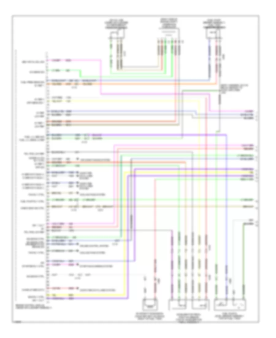
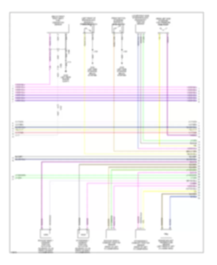
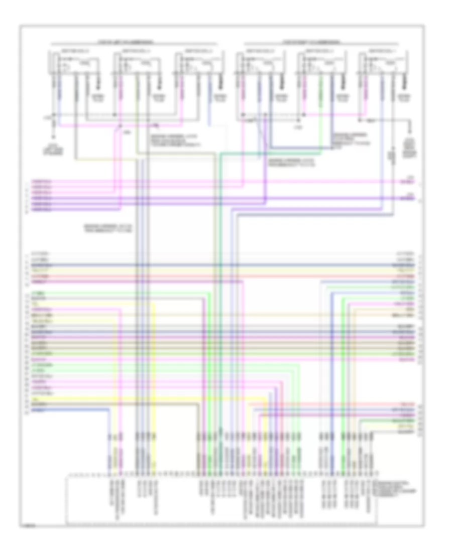
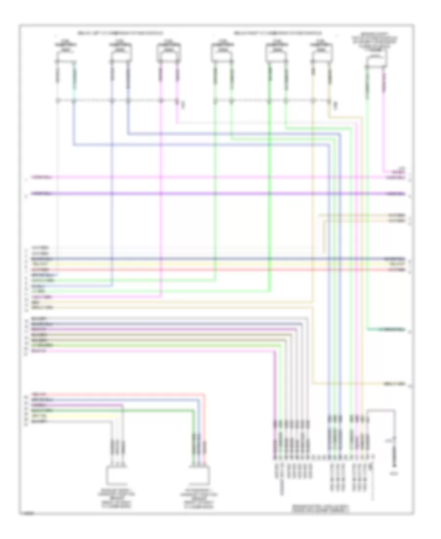
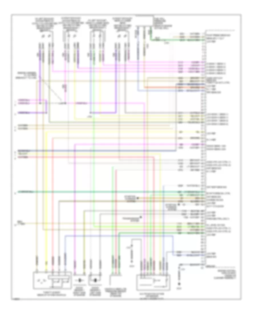
3.6L VIN 3, Engine Performance Wiring Diagram (1 of 7) for Chevrolet Impala LT 2014
List of elements for 3.6L VIN 3, Engine Performance Wiring Diagram (1 of 7) for Chevrolet Impala LT 2014:
- (fuel pump/sender assembly) fuel tank pressure sensor
- (top of accelerator pedal assembly) accelerator pedal position sensor
- 5v ref 2
- 5v ref 3
- 5v ref 4
- 5v reference 1
- A/c clutch rly ctrl
- A/c pressure sens 5v ref 1
- A/c refrigerant pressure sens sig
- A/c refrigerant pressure sensor (on a/c line, under air cleaner)
- Air conditioning system
- Air inj pmp sen 2 gnd
- Air inj pmp sen 2 sply volt
- Air inj reaction sol rly c0il ctrl
- App sens sig (1)
- App sens sig (2)
- Batt pos vol
- Brake pedal position sensor (top of brake pedal assembly)
- Brk pedal pos sen sig
- Check engine ind ctrl
- Coil ctrl
- Computer data lines system
- Cooling fan rly ctrl
- Cooling fans system
- Cruise control system
- Ecm ign fuse 5a
- Engine control module (ecm) (inside air cleaner assembly)
- Etc/tcc brake sig
- Evap canister vent sol ctrl
- Evaporative emission vent solenoid valve (right of fuel tank)
- Fuel level sensor
- Fuel pump
- Fuel pump & level sensor assembly (top of fuel tank)
- Fuel pump rly ctrl
- Fuel tank press 5v ref
- Fuel tank pressure sens sig
- Fuel temp sig
- Gmlan serial data bus +
- Gmlan serial data bus -
- Hot w/ ignition main relay energized
- Ign vol 1
- J434 (body harness, 28.5 cm below branch to audio amplifier)
- Lo ref
- Low ref
- Low ref (2)
- Low speed cooling fan rly ctrl
- Powertrain main rly (1)
- Powertrain main rly (2)
- Powertrain main rly (3)
- Powertrain rly ctrl
- Pressure sens sig
- Primary fuel level sens sig
- Sens 2 sig
- Sens low ref
- Starter rly ctrl
- Starting/charging system
- Underhood fuse block (right side of engine compt)
- Wake-up sig
- X115
- X117
- X150
- X210
- X350
3.6L VIN 3, Engine Performance Wiring Diagram (2 of 7) for Chevrolet Impala LT 2014
List of elements for 3.6L VIN 3, Engine Performance Wiring Diagram (2 of 7) for Chevrolet Impala LT 2014:
- (body harness, 23.5 cm below branch to audio amplifier)
- (body harness, 44.3 cm from chassis control module) j455
- (california) j227
- 5-v ref
- Active grille air shutter actuator (front center of grille opening)
- Aero fuse 5a
- Batt pos vol
- Cann vnt fuse 10a
- Ccm fuse 20a
- Chassis control module (right rear luggage compt)
- Coil even fuse 15a
- Coil odd fuse 15a
- Computer data lines system
- Cooling fans system
- Driver information center display
- Ecm batt fuse 5a
- Ecm fuse 25a
- Engine controls ignition relays
- Engine oil ind
- Fan rly a fuse 10a
- Fuel gauge
- Fuel ind
- Fuel pressure sensor (right side of fuel tank)
- Fuel pump low ref
- Fuel shld extsn
- G101 (engine compt center front)
- G405 (luggage compt, right wheel well)
- Gnd
- Hot at all times
- Hot w/ ignition main relay energized
- Ign
- Ign vol 1
- Instrument cluster
- J101
- J433
- Logic
- Low ref
- Mil ind
- Non walk pt fuse 10a
- Non walk veh fuse 10a
- Power distribution system
- Press sens sig
- Pump rly ctrl
- Pump supy vol
- Ser data bus +
- Ser data bus -
- Ser data comm
- Serial data
- Shutter valve
- Sol ctrl
- Tcm/ ccm ign fuse 7.5a
- To secondary air injection pump relay (diagram 3 of 7)
- Underhood fuse block (right side of engine compt)
- X105
- X115
- X150
- X350
3.6L VIN 3, Engine Performance Wiring Diagram (3 of 7) for Chevrolet Impala LT 2014
List of elements for 3.6L VIN 3, Engine Performance Wiring Diagram (3 of 7) for Chevrolet Impala LT 2014:
- (engine harness, engine control module approximately 5 cm from main bundle) j117
- Exhaust bank 2 camshaft position actuator solenoid valve (front of left cylinder bank)
- From non walk veh fuse (diagram 2 of 7)
- G120 (left side of engine, below starter)
- Hot at all times
- Intake bank 2 camshaft position actuator solenoid valve (front of left cylinder bank)
- J120
- Nca
- Sair pump fuse 50a
- Sair sol fuse 15a
- Secondary air injection pump (california)
- Secondary air injection pump relay (california)
- Secondary air injection solenoid valve bank 1 (california) (on bank 1 cylinder head)
- Secondary air injection solenoid valve bank 2 (california) (on bank 1 cylinder head)
- Secondary air injection solenoid valve relay (california)
- Underhood fuse block (right side of engine compt)
- X114
3.6L VIN 3, Engine Performance Wiring Diagram (4 of 7) for Chevrolet Impala LT 2014
List of elements for 3.6L VIN 3, Engine Performance Wiring Diagram (4 of 7) for Chevrolet Impala LT 2014:
- (below front right seat) fuel composition sensor
- (front bottom of engine) engine oil level switch
- (left front of engine block) engine oil pressure switch
- (lower right side of engine block) crankshaft position sensor
- (rear left side of engine) high pressure fuel pump
- Engine coolant temperature sensor (left rear of left cylinder head)
- Exhaust bank 1 camshaft position actuator solenoid valve (front of right cylinder bank)
- Exhaust bank 2 camshaft position sensor (front of left cylinder bank)
- G109 (left rear engine compt)
- G120 (left side of engine, below starter)
- Intake bank 1 camshaft position actuator solenoid valve (front of right cylinder bank)
- Intake bank 2 camshaft position sensor (front of left cylinder bank)
- J114
- J120
- X115
- X150
- X190
3.6L VIN 3, Engine Performance Wiring Diagram (5 of 7) for Chevrolet Impala LT 2014
List of elements for 3.6L VIN 3, Engine Performance Wiring Diagram (5 of 7) for Chevrolet Impala LT 2014:
- (engine harness, 10 cm from breakout to g122) j103
- (engine harness, 35.3 cm from breakout to x160)
- (engine harness, 4.5 cm from main bundle toward formed conduit)
- (engine harness, 5.9 cm from breakout to x115)
- (top of left cylinder bank)
- (top of right cylinder bank)
- Actuator hi ctrl
- Actuator low ctrl
- Crk shf 6ox sens
- Ect sens sig
- Engine control module (ecm) (inside air cleaner assembly)
- Exhaust sens 1 sig
- Exhaust sens 2 sig
- Exhaust solend (1)
- Exhaust solend (2)
- Exhaust sply (1)
- Fuel inj 1 ctrl
- Fuel inj 2 ctrl
- Fuel inj 3 ctrl
- Fuel inj 4 ctrl
- Fuel inj 5 ctrl
- Fuel inj 6 ctrl
- G122 (right rear engine compt)
- G123 (left side of engine)
- Ic 1 ctrl
- Ic 2 ctrl
- Ic 3 ctrl
- Ic 4 ctrl
- Ic 5 ctrl
- Ic 6 ctrl
- Ignition coil 1
- Ignition coil 2
- Ignition coil 3
- Ignition coil 4
- Ignition coil 5
- Ignition coil 6
- Intake sens 1 sig
- Intake sens 2 sig
- Intake sens sply 1
- Intake sens sply 2
- Intake solend (1)
- Intake solend (2)
- J106
- J119
- J122
- J133
- Low ref
- Nca
- Oil pressure sw sig
- Spark plug
3.6L VIN 3, Engine Performance Wiring Diagram (6 of 7) for Chevrolet Impala LT 2014
List of elements for 3.6L VIN 3, Engine Performance Wiring Diagram (6 of 7) for Chevrolet Impala LT 2014:
- (below left cylinder bank intake manifold)
- (below right cylinder bank intake manifold)
- (engine compt, top of intake manifold) evaporative emission purge solenoid valve
- Engine control module (ecm) (inside air cleaner assembly)
- Exhaust bank 1 camshaft position sensor (front of right cylinder bank)
- Exhaust sply (2)
- Fuel inj 1 ctrl
- Fuel inj 2 ctrl
- Fuel inj 3 ctrl
- Fuel inj 4 ctrl
- Fuel inj 5 ctrl
- Fuel inj 6 ctrl
- Fuel injector 1
- Fuel injector 2
- Fuel injector 3
- Fuel injector 4
- Fuel injector 5
- Fuel injector 6
- G121
- Gnd
- Intake bank 1 camshaft position sensor (front of right cylinder bank)
- J121
- Low ref
- X160
- X161
3.6L VIN 3, Engine Performance Wiring Diagram (7 of 7) for Chevrolet Impala LT 2014
List of elements for 3.6L VIN 3, Engine Performance Wiring Diagram (7 of 7) for Chevrolet Impala LT 2014:
- (engine harness, 9.1 cm from breakout to x160)
- (in left exhaust, downstream of catalytic converter) heated oxygen sensor bank 2 sensor 2
- (in left exhaust, near cylinder head) heated oxygen sensor bank 2 sensor 1
- (in right exhaust, downstream of catalytic converter) heated oxygen sensor bank 1 sensor 2
- (in right exhaust, near cylinder head) heated oxygen sensor bank 1 sensor 1
- 5-v 1 ref
- 5-v 3 ref
- 5-v 4 ref
- Air temp sens sig
- Charge ind sig
- Duty cycle sig
- Engine control module (ecm) (inside air cleaner assembly)
- Evap purge sol ctrl
- Frp sens sig
- Fuel rail pressure sensor (rear of engine on fuel rail)
- G121
- Ground
- Hi bank 1 sens (1)
- Hi bank 1 sens (2)
- Hi bank 2 sens (1)
- Hi bank 2 sens (2)
- Ho2s htr low ctrl (1)
- Ho2s htr low ctrl (2)
- J107
- J108
- J121
- Knock sens 1 sig
- Knock sens 2 sig
- Knock sensor 1 (right side of engine)
- Knock sensor 2 (left side of engine)
- Low bank 1 sens (1)
- Low bank 1 sens (2)
- Low bank 2 sens (1)
- Low bank 2 sens (2)
- Low ref
- Maf sens sig
- Manifold absolute pressure sensor (rear top of engine)
- Map sens sig
- Mass air flow sens sig throttle actu ctrl
- Multifunction intake air sensor (in air cleaner duct)
- Oil level sw sig
- Park/neutral sig (1)
- Pump press sens sig
- Sens sig
- Sens sply volt
- Starting/ charging system
- Throttle body (rear of intake manifold)
- Transmissions system
- X161
EXTERIOR LIGHTS
Backup Lamps Wiring Diagram for Chevrolet Impala LT 2014
List of elements for Backup Lamps Wiring Diagram for Chevrolet Impala LT 2014:
- 2.4l hybrid & 2.5l
- 3.6l
- Automatic transmission assembly
- Backup lamp sply volt
- Backup lp sply volt
- Battery positive volt
- Bcm 6 fuse 15a
- Body control module (left side of dash)
- Computer data lines system
- Control solenoid valve assembly
- Engine control module (inside air cleaner assembly)
- G121 (hybrid: front center engine compt) (except hybrid: rear center engine compt)
- G203 (base of left "a" pillar)
- G403 (luggage compt, left wheel well)
- G405 (luggage compt, right wheel well)
- Ground
- Hi spd gmlan serial data +
- Hi spd gmlan serial data -
- Hot at all times
- Inside rearview mirror (if equipped)
- J121
- J209
- J338 (body harness, 15 cm rearward of breakout to x700)
- J405
- J436
- J995
- Left backup lamp
- Left rear side marker lamp
- Left tail lamp assembly
- Left tail/ stop & turn signal lamp
- Logic
- Rearview camera (if equipped)
- Right backup lamp
- Right rear side marker lamp
- Right tail lamp assembly
- Right tail/ stop & turn signal lamp
- Signal ground
- Transmission control module
- Transmission internal mode switch
- Transmission park/neutral sig
- Underhood fuse block (right side of engine compt)
- X410
- X420
- X900
- X915
Exterior Lamps Wiring Diagram (1 of 3) for Chevrolet Impala LT 2014
List of elements for Exterior Lamps Wiring Diagram (1 of 3) for Chevrolet Impala LT 2014:
- 5 volt ref
- Auto
- Battery positive volt
- Battery positive volt x5
- Bcm 1 fuse 15a
- Bcm 3 fuse 15a
- Bcm 4 fuse 15a
- Bcm 6 fuse 15a
- Bcm 7 fuse 10a
- Body control module (left side of dash)
- Brake pedal position sensor (top of brake pedal assembly)
- Brk position sens lo ref
- Brk position sens sig
- Computer data lines system
- Engine control module (ecm) (inside air cleaner assembly)
- Except hybrid
- G121 (hybrid: front center engine compt) (except hybrid: rear center engine compt)
- G203 (base of left "a" pillar)
- Ground
- Hazard led dimming sig
- Hazard sw left turn sig
- Hazard sw right turn sig
- Hazard sw sig
- Hazard warning switch
- Head
- Hi spd gmlan serial data +
- Hi spd gmlan serial data -
- Hot at all times
- Hybrid
- Hybrid/ev battery pack (luggage compt, behind rear seats)
- Hybrid/ev powertrain control module
- Instrument panel fuse block (right kick panel)
- J121
- J209
- Left
- Left park lp sply volt
- Lf turn sig sply volt
- Lr stop/turn sig sply volt
- Off
- Park
- Park lamp sig
- Rear license lmp sply volt
- Rf turn sig sply volt
- Right
- Right park lp sply volt
- Rr stop/turn sig sply volt
- Signal ground
- Starter/generator control module
- Stp lmp rly coil sply volt
- Turn signal/ multi-function switch
- Underhood fuse block (right side of engine compt)
- X115
- X210
- X900
- X915
Exterior Lamps Wiring Diagram (2 of 3) for Chevrolet Impala LT 2014
List of elements for Exterior Lamps Wiring Diagram (2 of 3) for Chevrolet Impala LT 2014:
- (body harness, 30 cm rearward of breakout to x700) j340
- Backup lamps circuit
- Center high mounted stop lamp
- Driver outside rearview mirror
- Driver outside rearview mirror lamp assembly
- G101 (engine compt center front)
- G203 (base of left "a" pillar)
- G302 (right front "a" pillar)
- G401 (luggage compt, left wheel well)
- G403 (luggage compt, left wheel well)
- Ground distribution system
- Headlights system
- J101
- J105
- J110
- J152 (forward lamp harness, 31.3 cm rear of breakout to x120)
- J402
- J405
- J500
- J600
- Left backup lamp
- Left front park lamp
- Left front side marker lamp
- Left front turn signal lamp
- Left headlamp assembly
- Left license plate lamp
- Left park/ turn signal lamp
- Left park/daytime running lamp (if equipped)
- Left rear side marker lamp
- Left tail lamp
- Left tail lamp assembly
- Left tail/ stop & turn signal lamp
- Left turn signal repeater lamp
- Logic
- Passenger outside rearview mirror
- Passenger outside rearview mirror lamp assembly
- Red
- Right license plate lamp
- Right turn signal repeater lamp
- W/ hid
- W/o hid
- X105
- X110
- X150
- X410
- X500
- X510
- X600
- X610
- X900
Exterior Lamps Wiring Diagram (3 of 3) for Chevrolet Impala LT 2014
List of elements for Exterior Lamps Wiring Diagram (3 of 3) for Chevrolet Impala LT 2014:
- Backup lamps circuit
- Computer data lines system
- Driver information center display
- G101 (engine compt center front)
- G102 (center engine compt on frame rail)
- G401 (luggage compt, left wheel well)
- G405 (luggage compt, right wheel well)
- Ground distribution system
- Headlights system
- Instrument cluster
- J102
- J105
- J111
- J151 (forward lamp harness, 5 cm from breakout to fuse block - underhood to breakout to x110)
- J344 (body harness, 15 cm from breakout to x320)
- J436
- Left turn ind
- Logic
- Park lamps ind
- Red
- Right backup lamp
- Right front park lamp
- Right front side marker lamp
- Right front turn signal lamp
- Right headlamp assembly
- Right park/ turn signal lamp
- Right park/daytime running lamp (if equipped)
- Right rear side marker lamp
- Right tail lamp
- Right tail lamp assembly
- Right tail/ stop & turn signal lamp
- Right turn ind
- Serial data (+) most
- Serial data (-) most
- W/ hid
- W/o hid
- X105
- X120
- X150
- X420
- X900
GROUND DISTRIBUTION
Ground Distribution Wiring Diagram (1 of 7) for Chevrolet Impala LT 2014
List of elements for Ground Distribution Wiring Diagram (1 of 7) for Chevrolet Impala LT 2014:
- (2.5l & 3.6l) fuel composition sensor
- (engine compt center front)
- (forward lamp harness, 7 cm forward of breakout to g109)
- (hybrid) diode
- (w/ adaptive cruise control) distance sensing cruise control module
- 35 cm from x105)
- 85a
- 87a
- Active grille air shutter actuator
- Child security lock disable relay
- Cooling fan speed control relay
- G101
- G109 (left rear engine compt)
- Hood ajar switch
- Horn assembly
- Ignition main relay
- J100
- J101 (forward lamp harness, 1.4 cm from breakout to underhood fuse block toward breakout to x110)
- J110
- Left front park lamp
- Left front side marker lamp
- Left front turn signal lamp
- Left headlamp assembly
- Left headlamp ballast
- Left high beam solenoid actuator
- Left low beam headlamp
- Left park daytime running lamp
- Left park/turn signal lamp
- Logic
- Rear compartment lid unlatch relay
- Rear defogger relay
- Right park daytime running lamp
- Underhood fuse block (right side of engine compt)
- W/ drl
- W/ halogen headlamps
- W/ hid headlamps
- W/o drl
- Windshield washer fluid level switch
- Windshield washer pump
- Windshield washer pump relay
- Windshield wiper motor
- Windshield wiper relay
- X105
- X110
- X190
Ground Distribution Wiring Diagram (2 of 7) for Chevrolet Impala LT 2014
List of elements for Ground Distribution Wiring Diagram (2 of 7) for Chevrolet Impala LT 2014:
- (california) secondary air injection pump
- (california) secondary air injection solenoid valve bank 1
- (california) secondary air injection solenoid valve bank 2
- (lower left rear of engine)
- (right side of engine compt) underhood fuse block
- (w/ navigation) human machine interface control module
- (w/o belt drive) x1
- 3.6l & 2.4l
- A/c compressor
- A/c compressor clutch
- Audio amplifier
- Auxiliary audio input
- Battery
- Battery current sensor
- Body control module (bcm)
- Brake booster pump motor relay
- Electronic brake control module
- Engine oil level switch
- Engine oil pressure switch
- G100 (left side of engine, near starter)
- G102 (center engine compt on frame rail)
- G103 (left front engine compt frame rail)
- G106 (center engine compt on frame rail)
- G110 (left front engine compt)
- G111
- G120 (3.6l) (left side of engine, below starter)
- G205 (right front "a" pillar)
- Info display module
- J111
- J202 (i/p harness, 12.5 cm from breakout to left front tweeter speaker)
- J380 (body harness, 12.6 cm forward of breakout to x380)
- Left cooling fan motor
- Media disc player
- Passenger presence module
- Power steering control module
- Radio
- Right front park lamp
- Right front side marker lamp
- Right front turn signal lamp
- Right headlamp assembly
- Right headlamp ballast
- Right high beam solenoid actuator
- Right low beam headlamp
- Right park/turn signal lamp
- Starter relay
- Telematics communication interface control module
- W/ halogen headlamps
- W/ hid headlamps
- W/ onstar
- X1 (w/ belt drive)
- X120
- X300
Ground Distribution Wiring Diagram (3 of 7) for Chevrolet Impala LT 2014
List of elements for Ground Distribution Wiring Diagram (3 of 7) for Chevrolet Impala LT 2014:
- (2.4l)
- (2.4l) b
- (2.4l: engine harness, 4 cm from ignition coil 3 to ignition coil 2) (2.5l: engine harness, 6 cm from ignition coil 4 to branch to camshaft position sensors)
- (2.5l & 3.6l)
- (2.5l & 3.6l) multi-function intake air sensor (2.4l) mass air flow/intake air temperature sensor
- (2.5l) a
- (2.5l) secondary air injection solenoid valve (2.4l) secondary air injection solenoid valve cylinder 1/2
- (3.6l)
- (below driver seat)
- (except 3.6l)
- (right side of engine compt) underhood fuse block
- 87a
- A/c compressor
- A/c compressor clutch
- Automatic transmission assembly
- Auxiliary transmission fluid pump
- Center console accessory power receptacle
- Center console compartment lamp
- Center console multi-function switch
- Control solenoid valve assembly
- Engine control module
- Engine oil level switch
- G121 (2.4l: front center engine compt) (2.5l: rear center engine compt)
- G122 (2.4l & 2.5l) (rear center engine compt)
- G122 (3.6l) (right rear engine compt)
- G123 (3.6l) (left side of engine)
- G303 (below driver seat)
- G307
- G404 (right rear "c" pillar)
- Heater coolant pump
- Ignition coil 1
- Ignition coil 2
- Ignition coil 3
- Ignition coil 4
- Ignition coil 5
- Ignition coil 6
- Inflatable restraint sensing & diagnostic module
- Instrument panel accessory power receptacle
- J120 (2.4l: engine harness, 5.3 cm from main bundle) (2.5l: engine harness, 15 cm from main bundle)
- J121 (2.4l: engine harness, 11.2 cm from main bundle) (2.5l: engine harness, 4.1 cm from engine oil pressure control solenoid valve connector) (3.6l: engine harness, 40.3 cm from breakout to x160 toward branch to bank 2 ignition coils)
- J122
- J122 (engine harness, 5.5 cm from breakout to ignition coil 4 toward main bundle)
- J300 (console harness, between breakout to transmission shift position indicator & branch to x305)
- J301 (console harness, between breakout to transmission shift position indicator & branch to x305)
- J305
- Park position switch
- Right rear window defogger noise filter
- Secondary air injection pump
- Secondary air injection solenoid valve cylinder 3/4
- Starter relay
- Starter/ generator coolant pump
- Transmission manual shift switch
- Transmission shift lever
- Transmission shift lever position indicator
- Transmission shift lock control solenoid actuator
- X300
Ground Distribution Wiring Diagram (4 of 7) for Chevrolet Impala LT 2014
List of elements for Ground Distribution Wiring Diagram (4 of 7) for Chevrolet Impala LT 2014:
- (if equipped) inside rearview mirror
- (lt & lz option 1) driver door pocket flood lamp
- (manual a/c) ambient light/ sunload sensor
- (w/ ambient lamps) driver door accent lamp
- (w/ engine start switch) ignition mode switch
- (w/ forward collision alert) collision alert indicators
- (w/ lane departure warning) instrument panel multi-function switch
- (w/ passive entry) left rear exterior door handle assembly
- A x705
- Body control module
- Data link connector
- Driver door handle flood lamp
- Driver door latch assembly
- Driver door lock switch
- Driver exterior door handle assembly (w/ passive entry)
- Driver exterior door handle switch
- Driver outside rearview mirror
- Driver outside rearview mirror courtesy lamp
- Driver outside rearview mirror glass
- Driver outside rearview mirror lamps assembly
- Driver side object detection indicator
- Driver window switch
- Frontview camera module
- G203 (base of left "a" pillar)
- Hazard warning switch
- Hvac controls
- Hvac controls module
- If equipped
- Instrument cluster
- Instrument panel dimmer switch
- J209 (i/p harness, 3 cm from branch to left instrument panel switches)
- J500 (driver door harness, 5.1 cm from breakout to x510)
- J505
- J700
- J705
- Left lamp turn signal repeater
- Left rear door accent lamp
- Left rear door handle flood lamp
- Left rear door latch assembly
- Left rear exterior door handle switch
- Left rear window switch
- Lt option 1
- Lz option 1
- Mirror control module
- Outside rearview mirror switch
- Steering wheel angle sensor
- Turn signal multi-function switch
- W/ forward collision alert & lane departure warning
- W/ memory
- W/ side obstacle detection & rear cross traffic alert
- W/o memory
- X500
- X505 a8
- X510
- X700
Ground Distribution Wiring Diagram (5 of 7) for Chevrolet Impala LT 2014
List of elements for Ground Distribution Wiring Diagram (5 of 7) for Chevrolet Impala LT 2014:
- (2 way)
- (8 way)
- (if equipped) front seat heating control module
- (if equipped) keyless entry control module
- (if equipped) passenger back seat heating element
- (if equipped) passenger seat lumbar support switch
- (lt & lz option 1) passenger door pocket flood lamp
- (w/ ambient lamps) passenger door accent lamp
- (w/ passive entry) passenger exterior door handle assembly
- Blower motor
- G302 (right front "a" pillar)
- If equipped
- J234 (body harness, 17 cm from breakout to x220 toward x600)
- J320 (passenger seat cushion harness, in the passenger seat cushion)
- J322
- J325
- J600
- J605
- J800
- J805
- Lt option 1
- Lz option 1
- Passenger back seat blower motor
- Passenger cushion seat blower assembly
- Passenger cushion seat blower motor
- Passenger cushion seat heating element
- Passenger door handle flood lamp
- Passenger door latch assembly
- Passenger door lock switch
- Passenger exterior door handle switch
- Passenger outside rearview mirror
- Passenger outside rearview mirror courtesy lamp
- Passenger outside rearview mirror glass
- Passenger outside rearview mirror lamps assembly
- Passenger seat adjuster switch
- Passenger seat lumbar support pump
- Passenger seat temperature control module
- Passenger side object detection indicator
- Passenger window switch
- Right rear door accent lamp
- Right rear door handle flood lamp
- Right rear door latch assembly
- Right rear exterior door handle assembly (w/ passive entry)
- Right rear exterior door handle switch
- Right rear seat side air bag
- Right rear window switch
- Right turn signal repeater lamp
- W/ heated seats
- W/ manual seats w/o lumbar
- W/ power seats & lumbar
- W/ side obstacle detection & rear cross traffic alert
- W/ ventilation seats
- W/o ventilation seats
- X2 a
- X320
- X321
- X600
- X605 a8
- X610
- X800
- X805
Ground Distribution Wiring Diagram (6 of 7) for Chevrolet Impala LT 2014
List of elements for Ground Distribution Wiring Diagram (6 of 7) for Chevrolet Impala LT 2014:
- (body harness, 11 cm rearward of breakout, of branch to x500) j229
- (if equipped) accessory dc/ac power inverter module
- (if equipped) steering column tilt & telescope switch
- (left front "a" pillar)
- (right kick panel) instrument panel fuse block
- (steering wheel heater control module, in the steering wheel control module pigtail)
- (w/ electric sliding glass sunroof) sunroof motor
- (w/ electric sliding glass sunroof) sunroof sunshade motor module
- (w/ heated seats) driver back seat heating element
- (w/ memory)
- (w/ memory) seat memory control module
- (w/ power tilt & telescopic) steering column position control module
- (w/o memory)
- (w/o memory) driver seat lumbar support pump
- A x2
- Body control module
- Brake fluid level switch
- Center console multifunction switch
- Data link connector
- Driver back seat blower motor
- Driver cushion seat blower assembly
- Driver cushion seat blower motor
- Driver cushion seat heating element
- Driver seat adjuster switch
- Driver seat temperature control module
- Driver window motor
- G305
- Instrument panel compartment lamp
- Instrument panel multi-function switch
- Interior rear compartment lid unlatch switch
- J204
- J214 (accent lamp assembly harness, within the accent lamp assembly)
- J279
- J289 (steering wheel air bag harness, in the steering wheel air bag assembly)
- J299 (steering wheel harness, in the steering wheel)
- J310 (driver seat cushion harness, in the driver seat cushion, in main bundle between branch)
- J312
- J315
- J390 (sunroof harness, above headliner)
- J391 (sunroof harness, above headliner)
- Left horn switch
- Left instrument panel accent lamp
- Left instrument panel courtesy lamp
- Left middle instrument panel accent lamp
- Left rear window switch
- Left steering wheel controls switch
- Park brake control switch
- Passenger instrument panel air bag
- Radio presets steering wheel controls switch
- Radio volume steering wheel controls switch
- Retained accessory power relay
- Right horn switch
- Right instrument panel accent lamp
- Right instrument panel courtesy lamp
- Right steering wheel controls switch
- Steering
- Steering wheel air bag
- Steering wheel air bag coil
- Steering wheel heating control module
- W/ ambient lamps
- W/ heated seats
- W/ ventilation seats
- W/o lane departure warning & rear parking assist
- W/o ventilation seats
- Wheel heater
- X2 a
- X202
- X205
- X214
- X300
- X310
- X311
- X390 h
- X500
- X700
Ground Distribution Wiring Diagram (7 of 7) for Chevrolet Impala LT 2014
List of elements for Ground Distribution Wiring Diagram (7 of 7) for Chevrolet Impala LT 2014:
- (body harness, 10 cm forward of breakout to g403)
- (hybrid) hybrid/ev battery pack cooling fan
- (if equipped) garage door opener
- (if equipped) left sunshade
- (if equipped) rear parking assist control module
- (if equipped) rearview camera
- (if equipped) right sunshade
- (not used)
- (w/ passive entry) exterior rear compartment lid unlatch switch
- (w/o onstar) compass module
- Center console flood lamp
- Center high mounted stop lamp
- Chassis control module
- Dome lamp switch
- G401 (luggage compt, left wheel well)
- G403 (luggage compt, left wheel well)
- G405 (luggage compt, right wheel well)
- J399 (w/o sunroof: headliner harness, 75.5 cm forward of breakout to x400) (w/ sunroof: headliner harness, 32.8 cm rearward of breakout to left sunshade)
- J402
- J405 (body harness, 5 cm rearward of breakout to g401)
- J418 (rear bumper harness, 6 cm from breakout to x415)
- J436
- J900
- J915
- Lamps
- Left backup lamp
- Left front dome/reading
- Left license plate lamp
- Left rear seat side air bag
- Left rear side marker lamp
- Left side object sensor module
- Left sunshade mirror lamp
- Left tail lamp
- Left tail lamp assembly
- Left tail/stop and turn signal lamp
- Logic
- Parking brake control module
- Passenger air bag disable indicator
- Rear compartment courtesy lamp
- Rear compartment lid latch
- Rear dome/reading lamps
- Right backup lamp
- Right front dome/reading lamps
- Right license plate lamp
- Right rear side marker lamp
- Right side object sensor module
- Right sunshade mirror lamp
- Right tail lamp
- Right tail lamp assembly
- Sunroof switch (w/ electric sliding glass sunroof)
- Telematics button assembly
- W/ onstar
- W/ side obstacle detection & rear cross traffic alert
- X370
- X400
- X410
- X415
- X420
- X900
HEADLIGHTS
Headlights Wiring Diagram, with High Intensity Discharge (1 of 2) for Chevrolet Impala LT 2014
List of elements for Headlights Wiring Diagram, with High Intensity Discharge (1 of 2) for Chevrolet Impala LT 2014:
- (base of left "a" pillar) g203
- Ambient light sens sig
- Ambient light/ sunload sensor (top center of dash)
- Auto
- Automatic a/c
- Battery fuse block
- Battery positive volt
- Bcm 3 fuse 15a
- Bcm 4 fuse 15a
- Body control module (left side of dash)
- Computer data lines system
- Exterior lights system
- Flash to pass
- Fuse 250a x5
- G101 (engine compt center front)
- G203 (base of left "a" pillar)
- Gnd
- Hdlp dimmer
- Hdlp hi beam rly ctrl
- Hdlp low beam rly ctrl x5
- Hdlp sw flash to pass sig x3
- Hdlp sw hdlps off sig ctrl
- Hdlp switch on signal
- Hdlp switch park lp sig x1
- Head
- Headlamp high beam relay
- Headlamp low beam relay
- Hot at all times
- Hvac control module
- Instrument panel fuse block (right kick panel)
- J101
- J105
- J110
- J209
- Left headlamp assembly
- Left headlamp ballast
- Left high beam solenoid actuator
- Left low beam headlamp
- Left park/ daytime running lamp
- Lf drl sply volt
- Logic
- Low ref
- Low spd gmlan ser data
- Lt hi beam fuse 10a
- Lt hid fuse 15a
- Manual a/c
- Nca
- Off
- Park
- Park auto
- Red
- Rf drl sply volt
- Rt hi beam fuse 10a
- Rt hid fuse 15a
- Sw hi beam sig
- Turn signal/ multi-function switch
- Underhood fuse block (right side of engine compt)
- X105
- X110
- X150
Headlights Wiring Diagram, with High Intensity Discharge (2 of 2) for Chevrolet Impala LT 2014
List of elements for Headlights Wiring Diagram, with High Intensity Discharge (2 of 2) for Chevrolet Impala LT 2014:
- Computer data lines system
- Data com
- Exterior lights system
- G101 (engine compt center front)
- G102 (center engine compt on frame rail)
- High beam ind
- Instrument cluster
- J102
- J105
- J111
- Logic
- Low spd gmlan ser data
- Nca
- Park brake control switch (park brake assembly)
- Park brake ind
- Park lamp ind
- Parking brake control module (left rear wheel well)
- Release sig
- Right headlamp assembly
- Right headlamp ballast
- Right high beam solenoid actuator
- Right low beam headlamp
- Right park/ daytime running lamp
- Signal
- Sply vol
- Vol ref
- X105
- X120
- X210
Headlights Wiring Diagram, without High Intensity Discharge (1 of 2) for Chevrolet Impala LT 2014
List of elements for Headlights Wiring Diagram, without High Intensity Discharge (1 of 2) for Chevrolet Impala LT 2014:
- (base of left "a" pillar) g203
- Ambient light sens sig
- Ambient light/ sunload sensor (top center of dash)
- Auto
- Automatic a/c
- Battery fuse block
- Battery positive volt
- Bcm 3 fuse 15a
- Bcm 4 fuse 15a
- Body control module (left side of dash)
- Computer data lines system
- Flash to pass
- Fuse 250a x5
- G101 (engine compt center front)
- G203 (base of left "a" pillar)
- Gnd
- Hdlp dimmer
- Hdlp hi beam rly ctrl
- Hdlp sw flash to pass sig x3
- Hdlp sw hdlps off sig ctrl
- Hdlp switch on signal x1
- Hdlp switch park lp sig x1
- Head
- Headlamp high beam relay
- Hot at all times
- Hvac control module
- Instrument panel fuse block (right kick panel)
- J110
- J209
- Left headlamp assembly
- Left high beam solenoid actuator
- Left low beam headlamp
- Lf headlamp lo beam sply
- Low ref
- Low spd gmlan ser data
- Lt hi beam fuse 10a
- Manual a/c
- Off
- Park
- Park auto
- Red
- Rf headlamp lo beam sply
- Rt hi beam fuse 10a
- Sw hi beam sig
- Turn signal/ multi-function switch
- Underhood fuse block (right side of engine compt)
- X110
- X150
Headlights Wiring Diagram, without High Intensity Discharge (2 of 2) for Chevrolet Impala LT 2014
List of elements for Headlights Wiring Diagram, without High Intensity Discharge (2 of 2) for Chevrolet Impala LT 2014:
- Computer data lines system
- Data com
- G102 (center engine compt on frame rail)
- High beam ind
- Instrument cluster
- J111
- Logic
- Low spd gmlan ser data
- Park brake control switch (park brake assembly)
- Park brake ind
- Park lamp ind
- Parking brake control module (left rear wheel well)
- Release sig
- Right headlamp assembly
- Right high beam solenoid actuator
- Right low beam headlamp
- Signal
- Sply vol
- Vol ref
- X120
- X210
HORN
Horn Wiring Diagram for Chevrolet Impala LT 2014
List of elements for Horn Wiring Diagram for Chevrolet Impala LT 2014:
- (left front "a" pillar) g305
- (steering wheel air bag harness in the steering wheel air bag assembly) j288
- Battery fuse block
- Body control module (left side of dash)
- Fuse 250a
- G101 (engine compt center front)
- Horn assembly (right front of engine compt)
- Horn relay
- Horn rly ctrl x5
- Horn sw sig x3
- Horn/ d horn fuse 15a
- Hot at all times
- J101
- J289
- Left horn switch
- Red
- Right horn switch
- Steering wheel air bag coil
- Underhood fuse block (right side of engine compt)
- X1 a
- X2 a
- X202
INSTRUMENT CLUSTER
Instrument Cluster Wiring Diagram (1 of 3) for Chevrolet Impala LT 2014
List of elements for Instrument Cluster Wiring Diagram (1 of 3) for Chevrolet Impala LT 2014:
- Abs ind
- Air bag ind
- Ambient air temperature sensor (front of engine compt)
- Batt positive volt
- Bcm 6 fuse 15a
- Brake ind
- Charging ind
- Check engine ind ctrl
- Computer data lines system
- Display fuse 15a
- Disply ign fuse 5a
- Driver information center (dic) display
- Engine coolant temperature gauge
- Engine coolant temperature ind
- Esc ind
- Esc off ind
- Forward collision alert led ctrl
- Fuel gauge
- G203 (base of left "a" pillar)
- Gnd
- High beam ind
- Hot at all times
- Hot w/ ignition main relay energized
- Ign 1 volt
- Illumination
- Instrument cluster
- Instrument panel fuse block (right kick panel)
- Interconn network bus 12
- J207
- J209
- J339
- Lane departure warning ind
- Left turn ind
- Logic
- Low fuel warning lamp ind
- Low spd gmlan serial data
- Low tire pressure ind
- Low washer fluid ind crrl
- Malfunction lamp ind
- Most ctrl
- Most serial data (+)
- Most serial data (-)
- Navigation system
- Oil level ind
- Outside ambient air temp sens sig
- Outside ambient temp sens low ref
- Park ind
- Park lamps ind
- Reflected led display dimming ctrl
- Right turn ind
- Seat belt ind
- Security ind
- Service parking brake ind
- Speedometer
- Tachometer
- Tachometer ind
- Traction off ind
- Underhood fuse block (right side of engine compt)
- Wiper/ washer system
- X105
- X150
- X210
Instrument Cluster Wiring Diagram (2 of 3) for Chevrolet Impala LT 2014
List of elements for Instrument Cluster Wiring Diagram (2 of 3) for Chevrolet Impala LT 2014:
- (or 1936)
- Batt positive volt
- Body control module (left side of dash)
- Check engine ind ctrl
- Compass module (w/ compass display) (top of rear window shelf)
- Computer data lines system
- Coolant temp low ref x3
- Coolant temp sens sig
- Driver door latch assembly
- Driver window motor
- Engine control module (inside air cleaner assembly)
- Engine controls system
- Engine oil level switch (3.6l & 2.5l) (2.5l: bottom right center of engine) (3.6l: front bottom of engine)
- Fuel level sensor
- Fuel lvl low ref
- Fuel pump & level sensor assembly (top of fuel tank)
- G122 (2.5l) g120 (3.6l) (2.5l: rear center engine compt) (3.6l: left side of engine, below starter)
- G203 (base of left "a" pillar)
- G302 (right front "a" pillar)
- G307 (below driver seat)
- G401 (luggage compt, left wheel well)
- Gmlan serial data (+)
- Gmlan serial data (-)
- Gnd
- Ill
- J120
- J209
- J300
- J402
- J434 (body harness, 28.5 cm below branch to audio amplifier)
- J500
- J600
- J700
- J800
- J900
- Left rear door latch assembly
- Left rear window switch
- Lf door ajar sw sig
- Lift gate ajar sw sig 1
- Lin network bus 2
- Logic
- Lr door ajar sw sig
- Network bus 2
- Network bus 3
- Network bus 4
- Oil lvl sw sig
- Oil press sens low ref
- Oil press sens sig
- Oil pressure sw sig
- Passenger door latch assembly
- Passenger window switch
- Power distribution system
- Press sens 5 volt ref
- Primary fuel lvl sens
- Rap relay coil ctrl
- Rear compartment lid latch
- Rf door ajar sw sig
- Right rear door latch assembly
- Right rear window switch
- Rr door ajar sw sig
- Run rly coil ctrl
- Serial data +
- Serial data -
- Transmission shift lever position indicator
- X115
- X210
- X300
- X350
- X900
Instrument Cluster Wiring Diagram (3 of 3) for Chevrolet Impala LT 2014
List of elements for Instrument Cluster Wiring Diagram (3 of 3) for Chevrolet Impala LT 2014:
- 2.4l
- 3.6l
- Brake fluid level switch (on brake fluid reservoir)
- Brk fluid lvl
- Bus 12 network
- Computer data lines system
- Data com
- Down
- Electronic brake control module (in brake pressure modulator valve)
- Engine coolant temperature sensor (2.4l: right rear side of engine) (2.5l: rear top of engine) (3.6l: left rear of left cylinder head)
- Engine oil pressure sensor engine block (2.5l) (top center of engine)
- Engine oil pressure switch (2.4l) (rear top of engine)
- Engine oil pressure switch (3.6l) (left front of engine block)
- G120 (left side of engine, below starter)
- G305 (left front "a" pillar)
- Gmlan serial data (+)
- Gmlan serial data (-)
- Interior lights system
- J120
- J229
- Left
- Mute
- Park brake control switch (park brake assembly)
- Parking brake control module (left rear wheel well)
- Phone
- Release sig
- Right
- Right steering wheel controls switch
- Sel
- Signal
- Sply vol
- Vol ref
- X210
INTERIOR LIGHTS
Courtesy Lamps Wiring Diagram (1 of 2) for Chevrolet Impala LT 2014
List of elements for Courtesy Lamps Wiring Diagram (1 of 2) for Chevrolet Impala LT 2014:
- Batt pos volt
- Bcm 2 fuse 15a
- Bcm 5 fuse 15a
- Bcm 7 fuse 10a
- Body control module (left side of dash)
- Center console compartment lamp
- Computer
- Computer data lines system
- Courtesy
- Data lines
- Dome lamp switch
- Driver information center display
- G203 (base of left "a" pillar)
- G305 (left front "a" pillar)
- G307 (below driver seat)
- G401 (luggage compt, left wheel well)
- G403 (luggage compt, left wheel well)
- G405 (luggage compt, right wheel well)
- Gmlan serial data (+)
- Gmlan serial data (-)
- Gnd
- Hot at all times
- Inadvertent pwr ctrl
- Instrument cluster
- Instrument illumination circuit
- Instrument panel compartment lamp
- Instrument panel compartment lamp switch
- Instrument panel fuse block (right kick panel)
- Intr lp ctrl
- Intr lp defeat sw sig x1
- J204
- J209
- J300
- J398 (headliner harness, 53.2 cm forward of breakout to x400)
- J399
- J436
- J900
- Led ambient lighting ctrl 1 x6
- Left front dome/ reading lamps
- Left instrument panel courtesy lamp
- Left sunshade
- Left sunshade mirror lamp
- Lift gate ajar sw sig x6
- Logic
- Lp sw sig x7
- Nca
- Rear compartment courtesy lamp
- Rear compartment lid latch
- Rear dome/ reading lamps
- Red
- Right front dome/ reading lamps
- Right instrument panel courtesy lamp
- Right sunshade
- Right sunshade mirror lamp
- System
- Trunk lp ctrl
- X210
- X300
- X400
- X900
Courtesy Lamps Wiring Diagram (2 of 2) for Chevrolet Impala LT 2014
List of elements for Courtesy Lamps Wiring Diagram (2 of 2) for Chevrolet Impala LT 2014:
- (accent lamp assembly harness, within the accent lamp assembly) red
- (i/p harness, 5.5 cm from breakouts to x210 and jx200)
- Ajar sw sig
- Breakout to x700)
- Center console flood lamp
- Computer data lines system
- Driver door accent lamp
- Driver door handle flood lamp
- Driver door latch assembly
- Driver door pocket flood lamp
- Driver window switch
- G203 (base of left "a" pillar)
- G302 (right front "a" pillar)
- G305 (left front "a" pillar)
- G403 (luggage compt, left wheel well)
- J204
- J213
- J214
- J399
- J500
- J505
- J506
- J600
- J605
- J606
- J700
- J706
- J800
- J805
- J806
- Left instrument panel accent lamp
- Left middle instrument panel accent lamp
- Left rear door accent lamp
- Left rear door handle flood lamp
- Left rear door latch assembly
- Left rear window switch
- Lr door ajar sw sig
- Network bus 3
- Network bus 4
- Passenger door accent lamp
- Passenger door handle flood lamp
- Passenger door latch assembly
- Passenger door pocket flood lamp
- Passenger window switch
- Red
- Right instrument panel accent lamp
- Right rear door accent lamp
- Right rear door handle flood lamp
- Right rear door latch assembly
- Right rear window switch
- Rr door ajar sw sig
- W/ ambient interior door lamp
- W/o ambient interior door lamp
- X210
- X214
- X400
- X500
- X505
- X600
- X605
- X700
- X705
- X800
- X805
Instrument Illumination Wiring Diagram (1 of 2) for Chevrolet Impala LT 2014
List of elements for Instrument Illumination Wiring Diagram (1 of 2) for Chevrolet Impala LT 2014:
- (body harness, 5 cm rearward of breakout to x310) j332
- (left front "a" pillar) g305
- (w/ sun roof: headliner harness, 47.7 cm rearward of breakout to left sunshade)
- (w/o sun roof: headliner harness, 61.1 cm forward of breakout to x400)
- 5 volt ref
- Batt pos volt
- Bcm 1 fuse 15a
- Bcm 2 fuse 15a
- Bcm 5 fuse 15a
- Body control module (left side of dash)
- Computer data lines system
- Dimmer sw low ref
- Dimmer sw sig
- Dimming ctrl
- Dome lamp switch
- Driver door lock switch
- Driver seat memory switch (w/ memory)
- G203 (base of left "a" pillar)
- G302 (right front "a" pillar)
- G305 (left front "a" pillar)
- G401 (luggage compt, left wheel well)
- G403 (luggage compt, left wheel well)
- Garage door opener (if equipped)
- Hazard led dimming signal x1
- Hazard warning switch
- Head
- Headlamp sw park lp sig x1
- Hi spd gmlan serial data (-)
- Hot at all times
- Ind dimming ctrl
- Instrument panel dimmer switch
- Instrument panel fuse block (right kick panel)
- J204
- J209
- J396
- J399
- J402
- J505
- J507
- J605
- Led backlight
- Led backlight dimming ctrl x7
- Led dm sig
- Left front dome/ reading lamps
- Left steering wheel controls switch
- Lin intrcon net bus
- Lo spd gmlan
- Logic
- Low ref
- Low ref memory sw
- Mirror control module
- Off
- Outside rearview mirror switch (w/ memory)
- Outside rearview mirror switch (w/o memory)
- Park auto
- Passenger door lock switch
- Pnk
- Rear dome/ reading lamps
- Red
- Right front dome/ reading lamps
- Right steering wheel controls switch
- Seat memory control module
- Serial data (+)
- Steering wheel heating control module
- Sunroof switch (if equipped)
- Turn signal/ multi-function switch
- X202
- X310
- X400
- X500
- X505
- X506
- X600
Instrument Illumination Wiring Diagram (2 of 2) for Chevrolet Impala LT 2014
List of elements for Instrument Illumination Wiring Diagram (2 of 2) for Chevrolet Impala LT 2014:
- (base of left "a" pillar)
- (i/p harness, between breakout to hvac controls)
- (left rear luggage compt) rear parking assist control module
- (luggage compt, left wheel well)
- C12
- Center console multi-function switch
- Computer data lines system
- Disply ign fuse 5a
- Driver window switch
- Front view camera module
- G203
- G203 (base of left "a" pillar)
- G302 (right front "a" pillar)
- G305 (left front "a" pillar)
- G401 (luggage compt, left wheel well)
- G403
- G403 (luggage compt, left wheel well)
- Gnd
- Green led keypad
- Hot w/ ignition main relay energized
- Hvac control module
- Ignition mode switch
- Info display module
- Instrument cluster
- Instrument panel multi-function switch
- Interior rear compartment lid unlatch switch
- J204
- J208
- J209
- J229
- J230
- J234
- J339
- J399
- J402
- J505
- Keypad red led
- Left rear window switch
- Linear interconnect
- Linear interconnect network bus
- Linear interconnect network bus 3
- Linear interconnect network bus 4
- Lo spd gmlan
- Lo spd gmlan serial data
- Logic
- Low speed gmlan
- Network bus 3
- Park brake control switch
- Passenger air bag disable indicator
- Passenger air bag ind
- Passenger window switch
- Rear park assist disable sig
- Right rear window switch
- Ser data (-) (1) hi spd gmlan
- Serial data
- Telematics button assembly
- Telematics communication interface control module (top of rear window shelf)
- Transmission shift lever position indicator
- Underhood fuse block (right side of engine compt)
- W/ rear parking assist
- W/ start/stop engine system
- W/o rear parking assist
- Wrng ind
- X210
- X300
- X400
- X600
- X605
- X700
- X800
MEMORY SYSTEMS
Driver"s Memory Seat Wiring Diagram (1 of 2) for Chevrolet Impala LT 2014
List of elements for Driver"s Memory Seat Wiring Diagram (1 of 2) for Chevrolet Impala LT 2014:
- (not used)
- Batt pos volt
- Circuit breaker 13 25a
- Computer data lines system
- Down
- Driver seat adjuster switch
- Driver seat memory switch
- Exit
- Forward sw sig
- Front vertical dwn sw sig
- Front vertical up sw sig
- Fwd
- G305 (left front "a" pillar)
- Gnd
- Horizontal mtr snsr sig
- Hot at all times
- Instrument panel fuse block (right kick panel)
- Interior lights system
- J310
- Linear interconnect network bus 8
- Low ref
- Low speed gmlan
- Lumbar dwn sw sig
- Lumbar forward sw sig
- Lumbar rearward sw sig
- Lumbar up sw sig
- Mem 1 sw sig
- Mem seat fuse 5a
- Mem snsr hi ref (2)
- Mem sw set sig
- Rear vertical dwn sw sig
- Rear vertical up sw sig
- Rearward sw sig
- Recline forward sw sig
- Recline mtr pos snsr sig
- Recline rearward sw sig
- Rwd
- Seat memory control module
- Serial data
- Set
- Underhood fuse block (right side of engine compt)
- Vertical mtr pos snsr sig
- Vertical mtr snsr sig
- X210
- X310
- X500
- X505
- X506
Driver"s Memory Seat Wiring Diagram (2 of 2) for Chevrolet Impala LT 2014
List of elements for Driver"s Memory Seat Wiring Diagram (2 of 2) for Chevrolet Impala LT 2014:
- (driver's seat cushion harness, in the driver seat cushion, in main bundle between branch) j311
- Driver pwr seat lumbar mtr horizontal mtr forward ctrl
- Driver seat front vertical motor
- Driver seat horizontal motor
- Driver seat lumbar support pump
- Driver seat lumbar support valve assembly
- Driver seat rear vertical motor
- Driver seat recline motor
- Drv pwr seat lumbar mtr fwd ctrl
- Front vertical mtr dwn ctrl
- Front vertical mtr up ctrl
- Horizontal mtr rearward ctrl
- J319 (driver seat back harness, 1.5 cm below breakout to seat lumbar pump)
- Lumbar mtr dwn ctrl
- Lumbar mtr forward ctrl
- Lumbar mtr up ctrl
- Lumbar mtr up ctrl drv pwr seat
- Lumbar up motor
- Mtr down ctrl drv pwr seat lumbar
- Mtr rwd ctrl drv pwr seat lumbar
- Rear vertical mtr down ctrl
- Rear vertical mtr up ctrl
- Recline mtr forward ctrl
- Recline mtr rearward ctrl
- Red
- Seat memory control module
- X311
Memory Mirrors Wiring Diagram (1 of 2) for Chevrolet Impala LT 2014
List of elements for Memory Mirrors Wiring Diagram (1 of 2) for Chevrolet Impala LT 2014:
- B11
- B12
- Batt pos volt
- C11
- C12
- Computer data lines system
- Defogger system
- Driver outside rearview mirror
- Driver outside rearview mirror courtesy lamp
- Driver outside rearview mirror glass
- Driver outside rearview mirror lamp assembly
- Driver outside rearview mirror motor
- Driver side object detection indicator
- Drv mir mtr common ctrl
- Drv mir mtr rt (+) lt (-) ctrl
- Drv mir mtr up (+) dwn (-) ctrl
- Drv mir pos snsr high ref
- Drv mir pos snsr low ref
- Drv mir pos snsr lt (-) rt (+) sig
- Drv mir pos snsr up (+) dwn (-) sig
- Exterior lights system
- G203 (base of left "a" pillar)
- Gnd
- Hot at all times
- Interior lights system
- J228 (w/ garage door opener)
- J500
- J505
- Led dimming sig
- Left turn signal repeater lamp
- Linear interconnect network bus 8
- Mir ewl fuse 7.5a
- Mir sw low ref
- Mirror control module
- Mirror dimming
- Mirrors system
- Navigation system
- Outside rearview mir adjust sig
- Outside rearview mir select sig
- Pnk
- Power distribution system
- Red
- Tan
- Underhood fuse block (right side of engine compt)
- X500
- X505
- X510
Memory Mirrors Wiring Diagram (2 of 2) for Chevrolet Impala LT 2014
List of elements for Memory Mirrors Wiring Diagram (2 of 2) for Chevrolet Impala LT 2014:
- B11
- B12
- Batt pos volt
- C11
- C12
- Co-drv mir mtr common ctrl
- Co-drv mir mtr lt (-) rt (+) ctrl
- Co-drv mir mtr up (+) dwn (-) ctrl
- Co-drv mir pos sens high ref
- Co-drv mir pos sens low ref
- Co-drv mir pos snsr lt (-) rt (+) sig
- Co-drv mir pos snsr up (+) dwn (-) sig
- Computer data lines system
- Defogger system
- Driver seat memory switch
- Exit
- Exterior lights system
- G302 (right front "a" pillar)
- G305 (left front "a" pillar)
- Gnd
- Hot at all times
- Interior lights system
- J234
- J310
- J600
- Linear interconnect network bus 8
- Logic
- Low ref
- Low speed gmlan serial data
- Mem seat fuse 5a
- Navigation system
- Outside rearview mirror switch
- Passenger outside rearview mirror
- Passenger outside rearview mirror courtesy lamp
- Passenger outside rearview mirror glass
- Passenger outside rearview mirror lamp assembly
- Passenger outside rearview mirror motor
- Passenger side object detection indicator
- Passenger window switch
- Pnk
- Power distribution system
- Pwin frt fuse 30a
- Red
- Right turn signal repeater lamp
- Seat memory control module
- Set
- Set sig
- Sw sig
- Tan
- Underhood fuse block (right side of engine compt)
- X310
- X500
- X505
- X506
- X600
- X605
- X610
Memory Power Tilt & Power Telescopic Wiring Diagram for Chevrolet Impala LT 2014
List of elements for Memory Power Tilt & Power Telescopic Wiring Diagram for Chevrolet Impala LT 2014:
- Batt pos volt
- Battery positive voltage
- Computer data lines system
- Down switch signal
- Driver seat memory switch
- E (not used)
- Exit
- Forward switch signal
- G305 (left front "a" pillar)
- Gnd
- Ground
- Hot at all times
- Instrument panel fuse block (right kick panel)
- Interior lights system
- J204
- J310
- Linear interconnect network bus 8
- Low ref
- Low speed gmlan serial data
- Mem seat fuse 5a
- Rearward switch signal
- Seat memory control module
- Set
- Set sig
- Steering column position control module
- Steering column telescope motor
- Steering column tilt & telescope switch
- Steering column tilt motor
- Sw sig
- Telescope motor forward
- Telescope mtr rearward
- Telescope mtr return
- Telescope mtr signal
- Tilt motor down control
- Tilt motor return
- Tilt motor signal
- Tilt motor up control
- Tilt/tele fuse 15a
- Underhood fuse block (right side of engine compt)
- Up switch signal
- X310
- X500
- X505
- X506
NAVIGATION
Blind Spot Monitoring Wiring Diagram for Chevrolet Impala LT 2014
List of elements for Blind Spot Monitoring Wiring Diagram for Chevrolet Impala LT 2014:
- Batt pos volt
- Battery positive volt
- Computer data lines system
- Driv side object detection led sig (1)
- Driver outside rearview mirror
- Driver outside rearview mirror glass
- Driver side object detection indicator
- G203 (base of left "a" pillar)
- G302 (right front "a" pillar)
- G401 (luggage compt, left wheel well)
- Gmlan serial data
- Ground
- Hot at all times
- J401
- J417
- J418
- J500
- J600
- Left side object sensor module
- Low speed
- Low speed gmlan
- Obstcl fuse 10a
- Pass side object detection led sig (1)
- Passenger outside rearview mirror
- Passenger outside rearview mirror glass
- Passenger side object detection indicator
- Right side object sensor module
- Serial data
- Underhood fuse block (right side of engine compt)
- X415
- X500
- X510
- X600
- X610
Lane Departure Warning Wiring Diagram for Chevrolet Impala LT 2014
List of elements for Lane Departure Warning Wiring Diagram for Chevrolet Impala LT 2014:
- Alert led ctrl
- Batt pos volt
- Body control module (left side of dash)
- Collision alert indicators
- Computer data lines
- Computer data lines system
- Dimming ctrl
- Frontview camera module
- G203 (base of left "a" pillar)
- Gap up/down switch
- Gnd
- Ground
- Hi spd gmlan serial data (+)
- Hi spd gmlan serial data (-)
- Hot at all times
- Hot w/ ignition main relay energized
- Ign 1 volt
- Indicator dimming control
- Instrument cluster
- Instrument panel multifunction switch
- Ip ign fuse 5a
- J209
- J230
- J401
- Lane departure warning disable sw sig
- Lane departure warning disable switch
- Lane departure warning ind
- Lane departure warning ind ctrl
- Left steering wheel controls switch
- Lighting ctrl sw ref
- Lo spd gmlan serial data
- Logic
- Obstcl fuse 10a
- Steering wheel air bag coil
- System
- Underhood fuse block (right side of engine compt)
- Up/down sw sig
- X202
- X210
Navigation Wiring Diagram (1 of 5) for Chevrolet Impala LT 2014
List of elements for Navigation Wiring Diagram (1 of 5) for Chevrolet Impala LT 2014:
- (right rear passenger compt, mounted to c-pillar) radio antenna amplifier
- (under defroster grill panel) remote control door lock receiver
- Am/fm
- Antenna
- Aux audio comm sig
- Aux audio screen (2)
- Aux detection sig
- Auxiliary audio input
- Batt positive vol
- Coax
- Computer data lines system
- Fm/rfr
- G205 (right front "a" pillar)
- Gmlan serial data
- Ground
- Hd/xm
- Hot at all times
- Instrument panel fuse block (right kick panel)
- J200
- J202
- L aux audio sig (2)
- Logic
- Low ref
- Media disc player
- Most control
- Most serial data (+)
- Most serial data (-)
- Nca
- Network bus 10
- Positive voltage
- R aux audio sig (2)
- Radio
- Rdo fuse 15a
- Rfr
- Serial data (+)
- Serial data (-)
- Telephone voice sig
- X221
- X300
Navigation Wiring Diagram (2 of 5) for Chevrolet Impala LT 2014
List of elements for Navigation Wiring Diagram (2 of 5) for Chevrolet Impala LT 2014:
- (left front of roof) cellular phone microphone
- (or 5149)
- (or 5152)
- (right front "a" pillar) g205
- (top of rear window shelf) navigation antenna signal splitter
- (top of rear window shelf) telematics communication interface control module
- 1bu
- 2bu
- Audio sig
- Batt pos volt
- Bk usb srl data
- Camera signal 2
- Camera signal 2 +
- Cellular phone, navigation & digital radio antenna
- Coax
- Coaxial antenna gps sig
- Communication enable
- Computer data lines system
- Drain wire
- Gmlan serial data (+)
- Gmlan serial data (-)
- Gps
- Gps/cell
- Human machine interface control module (front right instrument panel)
- J202
- Low ref
- Microphone sig
- Most control
- Most serial data (+)
- Most serial data (-)
- Navigation display sig
- Navigation system
- Nca
- Network bus 5
- Red
- Ser data (+)
- Ser data (-)
- Signal ground
- Usb receptacle
- Usb srl data
- Voice recognition audio sig
- Voice sig
- W/ digital audio system s-band & hd
- W/ onstar
- W/o digital audio system s-band & hd
- W/o onstar
- X220
- X222
- X240
- X400
Navigation Wiring Diagram (3 of 5) for Chevrolet Impala LT 2014
List of elements for Navigation Wiring Diagram (3 of 5) for Chevrolet Impala LT 2014:
- Batt positive volt
- Battery pos volt
- Computer data lines system
- Display
- Display fuse 15a
- Down
- G205 (right front "a" pillar)
- G305 (left front "a" pillar)
- Gmlan serial data
- Ground
- Hot at all times
- Info display module
- Instrument panel fuse block (right kick panel)
- J202
- J207
- J289
- J299
- Left
- Lnetwork bus 10
- Logic
- Navi display sig
- Nca
- Network bus 12
- Network bus5 5
- Radio preset dn sig
- Radio preset up sig
- Radio vol dn sig
- Radio vol up sig
- Radio volume steering wheel controls switch
- Radio/hvac controls
- Right
- Right steering wheel controls switch
- Seek down
- Seek up
- Sel
- Steering wheel air bag coil
- Swc fuse 2a
- Tan
- X202
Navigation Wiring Diagram (4 of 5) for Chevrolet Impala LT 2014
List of elements for Navigation Wiring Diagram (4 of 5) for Chevrolet Impala LT 2014:
- (body harness, 16.5 cm rear of breakout to x380)
- C10
- C11
- G305 (left front "a" pillar)
- J299
- J432
- Left front radio volume compensator interior noise microphone
- Left rear window shelf speaker (w/ premium surround amplifier)
- Radio presets steering wheel controls switch
- Rear radio volume compensator interior noise microphone
- Red
- Right front door speaker
- Right front radio volume compensator interior noise microphone
- Right rear window shelf speaker (w/ premium surround amplifier)
- X400
- X600
Navigation Wiring Diagram (5 of 5) for Chevrolet Impala LT 2014
List of elements for Navigation Wiring Diagram (5 of 5) for Chevrolet Impala LT 2014:
- Amp fuse 25a
- Audio amplifier (center front of trunk)
- Batt pos volt
- Center instrument panel speaker (w/ premium surround amplifier)
- Computer data lines system
- Engine controls system
- Front center speaker (-)
- Front center spkr (+)
- G205 (right front "a" pillar)
- Gmlan serial data
- Hot at all times
- J380
- Left front door speaker
- Left front tweeter speaker
- Left rear door speaker
- Lf midrange speaker (+)
- Lf speaker +
- Lf speaker sig -
- Lf tweeter speaker (+)
- Lf tweeter speaker (-)
- Lr midrange speaker (-)
- Lr speaker (+)
- Lr speaker signal (-)
- Lr subwoofer speaker (+)
- Lr subwoofer speaker (-)
- Microphone 1 ret
- Microphone 1 sig
- Microphone 2 ret
- Microphone 2 sig
- Microphone 3 ret
- Microphone 3 sig
- Most control
- Rf speaker +
- Rf speaker sig -
- Rf tweeter speaker (+)
- Rf tweeter speaker (-)
- Right front tweeter speaker
- Right rear door speaker
- Right subwoofer spkr (+)
- Right subwoofer spkr (-)
- Rr speaker (+)
- Rr speaker signal (-)
- Sensor signal
- Serial data (+)
- Serial data (-)
- Sig ground
- Underhood fuse block (right side of engine compt)
- X210
- X220
- X500
- X700
- X800
Parking Assistant Wiring Diagram for Chevrolet Impala LT 2014
List of elements for Parking Assistant Wiring Diagram for Chevrolet Impala LT 2014:
- (luggage compt, left wheel well) g401
- Batt positive volt
- Body control module (left side of dash)
- Computer data lines system
- Engine compt)
- G203 (base of left "a" pillar)
- Gmlan serial data
- Ground
- Hi spd gmlan serial data (+)
- Hi spd gmlan serial data (-)
- Hot at all times
- Indicator dimming ctrl
- Instrument panel multi-function switch
- J209
- J401
- J402
- J415 (rear bumper harness, 14 cm from breakout to rear object sensor right outer toward rear object sensor right middle)
- J416 (rear bumper harness, 10 cm from breakout to rear object sensor left middle toward rear object sensor right middle)
- Led disable sig
- Left middle rear object sensor
- Left outer rear object sensor
- Lr corner obj sens sig
- Lr middle obj sens sig
- Obj sens low ref
- Obj sens sply volt
- Obstcl fuse 10a
- Parking assist ind
- Parking assist switch
- Rear park assist disable sig
- Rear parking assist control module (left rear luggage compt)
- Right middle rear object sensor
- Right outer rear object sensor
- Rr corner obj sens sig
- Rr middle obj sens sig
- Underhood fuse block (right side of
- X210
- X415
Rear View Camera Wiring Diagram for Chevrolet Impala LT 2014
List of elements for Rear View Camera Wiring Diagram for Chevrolet Impala LT 2014:
- Body ign fuse 10a
- Camera sig +
- Camera sig -
- Exterior lights system
- G401 (luggage compt, left wheel well)
- Hot w/ ignition main relay energized
- Human machine interface control module (front right instrument panel)
- J336
- J403 (body harness, 13.5 cm from main bundle)
- J404 (body harness, 44 cm from x900)
- J900
- J917
- J994
- J996
- J997
- J998
- J999
- Nca
- Rearview camera
- Red
- Underhood fuse block (right side of engine compt)
- X220
- X900
- X915
POWER DISTRIBUTION
Power Distribution Wiring Diagram (1 of 6) for Chevrolet Impala LT 2014
List of elements for Power Distribution Wiring Diagram (1 of 6) for Chevrolet Impala LT 2014:
- (body harness, 5 cm forward of breakout, of branch to x500) (w/ gare door opener) j228
- Abs pump fuse 60a
- Abs valve fuse 30a
- Amp fuse 25a
- Audio amplifier
- Batt rvc fuse 5a
- Battery
- Battery fuse block
- Bcm 6 fuse 15a
- Body control module
- Brake booster pump motor relay (2.4l & 3.6l)
- Brk vac pump fuse 20a
- Ccm fuse 20a
- Chassis control module
- Driver window switch
- Ecm batt fuse 5a
- Electronic brake control module
- Engine control module
- Epb fuse 30a
- Front seat heating control module (if equipped)
- Fuse 100a
- Fuse 250a
- Fuse 300a
- Fuse 30a
- Fuse 60a
- Fuse 80a
- Garage door opener (if equipped)
- Generator
- Htd seat lf fuse 15a
- Htd seat rf fuse 15a
- Keyless entry control module (if equipped)
- Left rear window switch
- Mem seat fuse 5a
- Mir ewl fuse 7.5a
- Mirror control module
- Outside rearview mirror switch
- Parking brake control module
- Passenger window switch
- Peps batt fuse 5a
- Power steering control module (w/ belt drive)
- Power steering control module (w/o belt drive)
- Pwin frt fuse 30a
- Pwin rr fuse 30a
- Rap fuse 30a
- Red
- Right rear window switch
- Seat memory control module
- Starter motor
- Sunroof fuse 30a
- Sunroof motor (if equipped)
- Sunroof sunshade motor module (if equipped)
- To ignition main relay (diagram 2 of 6)
- To instrument panel fuse block (diagram 2 of 6)
- To instrument panel fuse block (diagram 4 of 6)
- Underhood fuse block (right side of engine compt)
- W/ memory
- W/o memory
- X210
- X310
- X320
- X390
- X400
- X500
- X505
- X600
- X605
- X700
- X800
Power Distribution Wiring Diagram (2 of 6) for Chevrolet Impala LT 2014
List of elements for Power Distribution Wiring Diagram (2 of 6) for Chevrolet Impala LT 2014:
- (body harness, 25 cm rearward of breakout to x700) j339
- (not used)
- 7.5a
- Active grille air shutter actuator (if equipped)
- Aero shutter fuse 5a
- Air bag fuse 10a
- Auxiliary heater coolant pump relay (hybrid)
- Bcm 2 fuse 15a
- Bcm 3 fuse 15a
- Body control module
- Body ign fuse 10a
- Body ign2 fuse 15a
- Bpim ign fuse 5a
- C12
- Cabin cool pmp fuse 5a
- Chassis control module (hybrid)
- Data link connector
- Disply ign fuse 5a
- Dlc fuse 7.5a
- Dlis fuse 2a
- Driver cushion seat blower assembly
- Driver seat temperature control module
- Ecm ign fuse 5a
- Engine control module
- From battery fuse block (diagram 1 of 6)
- From body control module (diagram 6 of 6)
- From ccm fuse d (diagram 1 of 6)
- Fuse a
- G101 (engine compt center front)
- Hvac control module
- Hvac/ cntrl fuse 10a
- Hybrid/ev battery pack
- Ignition main relay
- Inflatable restraint sensing & diagnostic module
- Inside rearview mirror (if equipped)
- Instrument cluster
- Instrument panel fuse block (right kick panel)
- J100
- J331 (body harness, 6 cm forward x210 of breakout to x310)
- J336 (body harness, 5 cm rearward of breakout to x700)
- J994
- Passenger air bag disable indicator
- Passenger cushion seat blower assembly
- Passenger presence module
- Passenger seat temperature control module
- Pnk
- Rear defogger relay
- Rearview camera (if equipped)
- Red
- Starter/ generator control module
- Steering column fuse holder
- Steering wheel air bag coil
- Steering wheel heating control module (if equipped)
- To ignition switch (diagram 6 of 6)
- To ip ign (diagram 5 of 6)
- To starter fuse (diagram 3 of 6)
- Trunk rel fuse (diagram 4 of 6)
- Underhood fuse block (right side of engine compt)
- Windshield washer pump relay
- X105
- X210
- X310
- X320
- X400
- X900
- X915
Power Distribution Wiring Diagram (3 of 6) for Chevrolet Impala LT 2014
List of elements for Power Distribution Wiring Diagram (3 of 6) for Chevrolet Impala LT 2014:
- (3.6l: engine harness, 5.9 cm from breakout to x115) (2.4l: engine harness, 6.1 cm from breakout to crankshaft position sensor) (2.4l: engine harness, 16.9 cm from branch to rear of engine components) j106
- (3.6l: engine harness, 9.1 cm from breakout to x160) (2.5l: engine harness, 7 cm from g122) j107
- (engine harness, 35.3 cm from breakout to x160) (3.6l) j133
- 2.4l
- 2.5l
- 2.5l & 3.6l
- 3.6l
- 3.6l & 2.4l
- 3.6l & 2.5l
- A/c clutch fuse 10a
- A/c compressor clutch relay
- Auxiliary transmission fluid pump relay (hybrid)
- Bank 1 sensor 1 heated oxygen sensor (3.6l)
- Bank 1 sensor 2 heated oxygen sensor (3.6l)
- Bank 2 sensor 1 heated oxygen sensor (3.6l)
- Bank 2 sensor 2 heated oxygen sensor (3.6l)
- Bas pwr inverter fuse 175a
- Coil even fuse 15a
- Coil odd fuse 15a
- Cooling fan high speed relay
- Cooling fan low speed relay
- Cooling fan speed control relay
- Ecm fuse 25a
- Engine control module
- Engine controls ignition relay
- Engine oil pressure control solenoid valve (2.5l)
- Evaporative emission purge solenoid valve
- Fan rly a fuse 10a
- From a/c l compressor clutch relay (diagram 3 of 6)
- From e cabin cool pmp fuse (diagram 2 of 6)
- From engine controls ignition relay (diagram 3 of 6)
- Fuel composition sensor
- Heated oxygen sensor 1
- Heated oxygen sensor 2 (2.4l)
- Heated oxygen sensor 2 (2.5l)
- Hybrid/ev battery pack
- Ignition coil 1
- Ignition coil 2
- Ignition coil 3
- Ignition coil 4
- Ignition coil 5 (3.6l)
- Ignition coil 6
- J108 (2.5l: engine harness, 4 cm from branch to camshaft position sensors) (2.4l: engine harness, 4 cm from ignition coil 3) (3.6l: engine harness, 27.3 cm from breakout to x160)
- J227 (3.6l) (body harness, 15.9 cm forward of breakout, of branch to x500)
- Mass air flow/ intake air temperature sensor (2.4l)
- Multi-function intake air sensor
- Nca
- Non walk pt fuse 10a
- Non wlk pt fuse 10a
- Red
- Rocker arm actuator (2.5l)
- Sair pump fuse 50a
- Sair sol fuse 15a
- Secondary air injection pump relay (w/ california emission system)
- Secondary air injection solenoid valve relay (except hybrid)
- Secondary air injection solenoid valve relay (w/ california emission system)
- Secondary air injection solenoid valve relay (w/ california hybrid system)
- Starter fuse 30a
- Starter relay
- Starter/ generator coolant pump relay (hybrid)
- Starter/generator control module
- To ecm fuse (diagram 3 of 6)
- To front fog lamp relay (diagram 5 of 6)
- To sair sol fuse (diagram 3 of 6)
- Underhood fuse block (right side of engine compt)
- X10
- X150
- X190
Power Distribution Wiring Diagram (4 of 6) for Chevrolet Impala LT 2014
List of elements for Power Distribution Wiring Diagram (4 of 6) for Chevrolet Impala LT 2014:
- (diagram 2 of 6)
- (or red)
- (w/o ventilated seats: passenger seat x210 cushion harness, in the passenger seat cushion) (w/ ventilated seats: seat temperature x320 control module- passenger, in the passenger seat cushion vent mat) j322
- 110v ac phase a
- 110v ac phase b
- 220v ac phase a
- 220v ac phase b
- Accessory dc/ac power inverter module
- Accessory power receptacle 220v ac (220v ac) accessory power receptacle 110v ac (110v ac)
- Bcm 1 fuse 15a
- Bcm 4 fuse 15a
- Bcm 5 fuse 15a
- Bcm 7 fuse 15a
- Bcm 8 fuse 30a
- Blower motor
- Body control module
- Center console accessory power receptacle
- Center console compartment accessory power receptacle
- Driver seat adjuster switch
- Drvr/seat circuit breaker 25a
- From battery fuse block (diagram 1 of 6)
- From fuse 19 h
- From instrument panel fuse block (diagram 5 of 6)
- From underhood fuse block (diagram 1 of 6)
- Frt/ hvac fuse 40a
- G305 (left front "a" pillar)
- G307 (below driver seat)
- Gnd dc to ac inverter ctrl
- Instrument panel accessory power receptacle
- Instrument panel fuse block (right kick panel)
- J204
- J208
- J301
- Logic
- Nca
- Pass/seat circuit breaker 25a
- Passenger seat adjuster switch
- Passenger seat lumber support switch
- Pwr/ outlet1 fuse 20a
- Pwr/outlet2 fuse 20a
- Rear compartment lid unlatch relay
- Red
- Retained accessory power relay
- Seat memory control module
- To acdcinv (diagram 5 of 6)
- Transmission shift lever position indicator
- Trunk rel fuse 5a
- W/ 2 way power seat
- W/ 8 way power seat
- W/ memory
- W/o memory
- X210
- X300
- X310
Power Distribution Wiring Diagram (5 of 6) for Chevrolet Impala LT 2014
List of elements for Power Distribution Wiring Diagram (5 of 6) for Chevrolet Impala LT 2014:
- (body harness, 13.2 cm rearward of branch to left rear wheel well) j401
- (i/p harness, 10.1 cm from branch to left instrument panel switches) j210
- (i/p harness, 9.5 cm left of branches to right instrument panel components)
- (rear bumper harness, 71 cm from side object sensor module - right) j417
- (w/ vehicle gps communication system)
- 2.4l & 2.5l
- 3.6l
- Acdcinv fuse 30a
- Automatic transmission assembly
- Auxiliary audio input
- Auxiliary transmission fluid pump relay (hybrid)
- Center console multi-function switch (w/ heated seats)
- Chassis control module (except hybrid)
- Collision alert
- Collision alert indicator
- Collision alert,rear cross traffic alert, lane departure warning & side obstacle detection
- Control solenoid valve assembly
- Cool fan lo k1 fuse 40a
- Cooling fan low speed relay
- Display fuse 15a
- Distance sensing cruise control module
- Except hybrid
- From display f ign fuse (diagram 2 of 6)
- From sair sol m fuse (diagram 3 of 6)
- From trunk rel n fuse (diagram 4 of 6)
- Front fog lamp relay (if equipped)
- Front view camera module
- Frt wpr fuse 30a
- Headlamp high beam relay
- Headlamp low beam relay (w/ hid headlamps)
- Horn relay
- Human machine interface control module (w/ navigation)
- Hvac control module
- Hvac controls
- Hybrid
- Hybrid/ev battery pack cooling fan
- Info display module
- Instrument cluster
- Instrument panel fuse block (right kick panel)
- Ip ign fuse 5a
- J200
- J201 (i/p harness, in the instrument panel, left, on breakout to fuse block - instrument panel)
- Left side object sensor module
- Logic
- Logic/ mode fuse 30a
- Media disc player
- Mgu cool pmp fuse 10a
- Obstcl fuse 10a
- Power pack acc fuse 10a 15a
- Radio
- Rdo fuse 15a
- Rear parking assist control module
- Right side object sensor module
- Right steering wheel controls switch
- Starter/ generator coolant pump relay (hybrid)
- Steering column position control module (if equipped)
- Steering wheel air bag coil
- Swc fuse 2a
- Tcm/ccm ign fuse 7.5a
- Telematics communication interface control module
- Telematics fuse 10a
- Tilt/tele fuse 15a
- To accessory dc/ac power inverter module (diagram 4 of 6)
- To tcm batt fuse (diagram 6 of 6)
- Trans aux pmp fuse 30a
- Transmission control module
- Underhood fuse block (right side of engine compt)
- W/ forward
- W/ rear parking assist & w/ forward
- W/ rear parking assist & w/o forward collision alert,rear cross traffic alert, lane departure warning & side obstacle detection
- W/o forward collision alert
- Windshield wiper relay
- Windshield wiper speed control relay
- X115
- X150
- X202
- X210
- X300
- X415
Power Distribution Wiring Diagram (6 of 6) for Chevrolet Impala LT 2014
List of elements for Power Distribution Wiring Diagram (6 of 6) for Chevrolet Impala LT 2014:
- (base of left "a" pillar) g203
- (body harness, 18.6 cm from breakouts to starter/generator control module) j400
- (except hybrid)
- (hybrid)
- 2.4l & 2.5l
- 3.6l
- Acc
- Acc led
- Acc volt
- Acc volt run/crank ign 1 volt x3
- Automatic transmission assembly
- Body control module
- Bpim batt fuse 7.5a 10a
- Cann vent fuse 5a
- Control solenoid valve assembly
- Cool fan hi k2 fuse 40a
- Cooling fan high speed relay
- Evaporative emission vent solenoid valve
- Except hybrid
- From headlamp p high beam relay (diagram 5 of 6)
- From instrument panel fuse block (diagram 2 of 6)
- Hybrid
- Hybrid/ev battery pack
- Ign
- Ignition mode switch (w/ keyless engine start switch)
- Ignition switch (w/o keyless engine start switch)
- Interior lights system
- Key in ignition switch
- Keyless entry control module
- Led sig
- Low ref
- Mode ctrl
- Mode volt
- Off
- Run
- Run/crank ign 1 volt x2
- Run/crank rly coil ctrl x4
- Start
- Starter/generator control module
- Tcm batt fuse 15a
- To underhood fuse block (diagram 2 of 6)
- Transmission control module
- Underhood fuse block (right side of engine compt)
- W/ keyless engine start switch
- W/o keyless engine start switch
- X210
- X350
POWER DOOR LOCKS
Power Door Locks Wiring Diagram, with Passive Keyless Entry (1 of 4) for Chevrolet Impala LT 2014
List of elements for Power Door Locks Wiring Diagram, with Passive Keyless Entry (1 of 4) for Chevrolet Impala LT 2014:
- Accessory volt
- Antenna 1 sig hi
- Antenna 1 sig lo
- Antenna 2 sig hi
- Antenna 2 sig lo
- Antenna 3 sig hi
- Antenna 3 sig lo
- Bat pos volt
- Batt rvc fuse 5a
- Bcm 3 fuse 15a
- Bcm 5 fuse 15a
- Center console front keyless entry antenna (mounted to rear of hvac assembly)
- Center console rear keyless entry antenna (rear of center console compt)
- Computer data lines system
- Driver door latch assembly
- Driver window motor
- Driver window switch
- G203 (base of left "a" pillar)
- G302 (right front "a" pillar)
- Ground
- Hot at all times
- Ign 1 volt
- Ignition mode switch
- Instrument panel fuse block (right kick panel)
- J234
- J500
- Keyless entry control module (right a-pillar)
- Lo spd gmlan ser data
- Logic
- Mtr status
- Passive start sw 2 low ref
- Passive start sw sig 2
- Peps batt fuse 5a
- Rear compartment keyless entry antenna (front center of luggage compt)
- Red
- Sw sig
- Sw sig lf dr ajar
- Underhood fuse block (right side of engine compt)
- X210
- X300
- X500
- X505
Power Door Locks Wiring Diagram, with Passive Keyless Entry (2 of 4) for Chevrolet Impala LT 2014
List of elements for Power Door Locks Wiring Diagram, with Passive Keyless Entry (2 of 4) for Chevrolet Impala LT 2014:
- (base of left "a" pillar) g203
- Accessory volt
- Actr unlock ctrl
- Bat pos volt
- Body control module (left side of dash)
- Computer data lines system
- Display ign fuse 5a
- Dr lock ctrl (2)
- Driver door lock switch
- Driver information center display
- Exterior lights system
- G203 (base of left "a" pillar)
- G302 (right front "a" pillar)
- Gmlan serial data (+)
- Gmlan serial data (-)
- Ground
- Head lp high rly ctrl
- Head lp low rly ctrl
- Headlights system
- Hood status b sig
- Horn rly ctrl
- Horns system
- Hot w/ ignition main relay energized
- Ign 1 volt
- Instrument cluster
- Interior lights system
- J209
- J339
- J505
- J605
- Left rear sig
- Lh park lp sply volt
- Liftgate ajar sw sig
- Logic
- Passenger door lock switch
- Red
- Remote actr receive sig
- Remote actr rtn
- Remote actr trans sig
- Rh park lp sply volt
- Right rear sig
- Scty ind ctrl
- Scty lock rly ctrl
- Security ind
- Sw lock ctrl
- Sw lock sig
- Sw unlock ctrl
- Sw unlock sig
- Underhood fuse block (right side of engine compt)
- X210
- X500
- X505
- X600
- X605
Power Door Locks Wiring Diagram, with Passive Keyless Entry (3 of 4) for Chevrolet Impala LT 2014
List of elements for Power Door Locks Wiring Diagram, with Passive Keyless Entry (3 of 4) for Chevrolet Impala LT 2014:
- (body harness, 7 cm forward of breakout to x800) j346
- (part of hood latch) hood ajar switch
- Ambient light/sunload sensor (top center of dash)
- Antenna
- Automatic a/c
- Coax
- Fm/rfr
- G101 (engine compt center front)
- G203 (base of left "a" pillar)
- G302 (right front "a" pillar)
- G401 (luggage compt, left wheelwell)
- Hvac control module
- Hybrid
- Hybrid/ev battery pack (luggage compt, behind rear seats)
- J100
- J209
- J600
- J700
- J900
- Left rear door latch assembly
- Left rear window switch
- Logic
- Lr dr ajar sw sig
- Manual a/c
- Passenger door latch assembly
- Passenger window switch
- Radio antenna amplifier (right rear passenger compt, mounted to c-pillar)
- Rear compartment lid latch
- Receive sig remote actr
- Remote actr rtn
- Remote control door lock receiver (under defroster grill panel)
- Rf dr ajar sw sig
- Rfr
- Starter/generator control module
- Trans sig remote actr
- X150
- X210
- X600
- X700
Power Door Locks Wiring Diagram, with Passive Keyless Entry (4 of 4) for Chevrolet Impala LT 2014
List of elements for Power Door Locks Wiring Diagram, with Passive Keyless Entry (4 of 4) for Chevrolet Impala LT 2014:
- (base of left "a" pillar) g203
- (right front "a" pillar) g302
- (right side of engine compt) underhood fuse block
- Antenna sig hi
- Antenna sig lo
- Child security lock disable relay
- Co-drv dr ant sig hi
- Co-drv dr handle sw sig
- Driver door handle keyless entry antenna
- Driver exterior door handle assembly
- Driver exterior door handle switch
- Drv dr handle sw sig
- G101 (engine compt center front)
- G203 (base of left "a" pillar)
- G302 (right front "a" pillar)
- J100
- J235 (body harness, 12 cm from breakout to x220 toward x600)
- J345 (body harness, 5 cm rear of the breakout to passenger seat belt pretensioner)
- J500
- J600
- J700
- J800
- Keyless entry control module (right a-pillar)
- Left rear exterior door handle assembly
- Left rear exterior door handle switch
- Logic
- Lr dr handle sw sig
- Passenger door handle keyless entry antenna
- Passenger exterior door handle assembly
- Passenger exterior door handle switch
- Rear fascia keyless entry antenna (mounted to rear fascia support)
- Red
- Right rear door latch assembly
- Right rear exterior door handle assembly
- Right rear exterior door handle switch
- Right rear window switch
- Rr dr ajar sw sig
- Rr dr handle sw sig
- X500
- X600
- X700
- X800
Power Door Locks Wiring Diagram, without Passive Keyless Entry (1 of 3) for Chevrolet Impala LT 2014
List of elements for Power Door Locks Wiring Diagram, without Passive Keyless Entry (1 of 3) for Chevrolet Impala LT 2014:
- Actr unlock ctrl
- Bat pos volt
- Batt rvc fuse 5a
- Bcm 3 fuse 15a
- Bcm 5 fuse 15a
- Body control module (left side of dash)
- Computer data lines
- Dr lock ctrl (2)
- Driver door latch assembly
- Driver door lock switch
- Driver window motor
- Driver window switch
- Exterior lights
- G203 (base of left "a" pillar)
- G401 (luggage compt, left wheelwell)
- Gmlan serial data (+)
- Gmlan serial data (-)
- Ground
- Head lp high rly ctrl
- Head lp low rly ctrl x5
- Headlights system
- Hood status b sig
- Horn rly ctrl
- Horns system
- Hot at all times
- Instrument panel fuse block (right kick panel)
- Interior lights system
- J209
- J500
- J505
- J900
- Left rear sig
- Lh park lp sply volt
- Liftgate ajar sw sig
- Logic
- Mtr status
- Rear compartment lid latch
- Red
- Rh park lp sply volt
- Right rear sig
- Scty ind ctrl
- Scty lock rly ctrl
- Sw lock ctrl
- Sw lock sig
- Sw sig
- Sw sig lf dr ajar
- Sw unlock ctrl
- Sw unlock sig
- System
- Underhood fuse block (right side of engine compt)
- X500
- X505
Power Door Locks Wiring Diagram, without Passive Keyless Entry (2 of 3) for Chevrolet Impala LT 2014
List of elements for Power Door Locks Wiring Diagram, without Passive Keyless Entry (2 of 3) for Chevrolet Impala LT 2014:
- (body harness, 7 cm forward of breakout to x800) j346
- (part of hood latch) hood ajar switch
- Ambient light/sunload sensor (top center of dash)
- Automatic a/c
- G101 (engine compt center front)
- G203 (base of left "a" pillar)
- G302 (right front "a" pillar)
- Hvac control module
- Hybrid
- Hybrid/ev battery pack (luggage compt, behind rear seats)
- Interior lights system
- J100
- J209
- J600
- J605
- J700
- Left rear door latch assembly
- Left rear window switch
- Logic
- Lr dr ajar sw sig
- Manual a/c
- Passenger door latch assembly
- Passenger door lock switch
- Passenger window motor
- Rf dr ajar sw sig
- Starter/generator control module
- X150
- X600
- X605
- X700
Power Door Locks Wiring Diagram, without Passive Keyless Entry (3 of 3) for Chevrolet Impala LT 2014
List of elements for Power Door Locks Wiring Diagram, without Passive Keyless Entry (3 of 3) for Chevrolet Impala LT 2014:
- "a" pillar)
- (base
- Center display
- Child security lock disable relay
- Computer
- Data lines
- Display ign fuse 5a
- Driver
- G101 (engine compt center front)
- G203
- G302 (right front "a" pillar)
- Hot w/ ignition main relay energized
- Information
- Instrument cluster
- J100
- J209
- J235 (body harness, 12 cm from breakout to x220 toward x600)
- J339
- J345 (body harness, 5 cm rear of the breakout to passenger seat belt pretensioner)
- J800
- Logic
- Of left
- Right rear door latch assembly
- Right rear window switch
- Rr dr ajar sw sig
- Security ind
- System
- Underhood fuse block (right side of engine compt)
- X210
- X800
POWER MIRRORS
Electrochromic Mirror Wiring Diagram for Chevrolet Impala LT 2014
List of elements for Electrochromic Mirror Wiring Diagram for Chevrolet Impala LT 2014:
- (body harness, 15 cm rearward of breakout to x700) j338
- Backup lp sply volt run/crank ign 1 volt
- Body control module (left side of dash)
- Body ign fuse 10a
- Driver outside rearview mirror
- Driver outside rearview mirror glass
- Exterior lights system
- G203 (base of left "a" pillar)
- Ground
- Hot w/ ignition main relay energized
- Inside rearview mirror
- J230
- J336
- Logic
- Low reference
- Mirror dimming
- Nca
- Red
- Sig
- Sply volt x7
- Stop switch
- Underhood fuse block (right side of engine compt)
- X500
- X510
Power Mirrors Wiring Diagram for Chevrolet Impala LT 2014
List of elements for Power Mirrors Wiring Diagram for Chevrolet Impala LT 2014:
- Defogger system
- Down
- Driver outside rearview mirror
- Driver outside rearview mirror courtesy lamp
- Driver outside rearview mirror glass
- Driver outside rearview mirror lamp assembly
- Driver outside rearview mirror motor
- Driver side object detection indicator
- Electrochromic mirror circuit
- Exterior lights system
- G203 (base of left "a" pillar)
- G302 (right front "a" pillar)
- Hot at all times
- Interior lights system
- J228 (w/ garrage door opener)
- J500
- J505
- J600
- Left
- Left turn signal repeater lamp
- Mir ewl fuse 7.5a
- Mirror dimming
- Navigation system
- Outside rearview mirror switch
- Passenger outside rearview mirror
- Passenger outside rearview mirror courtesy lamp
- Passenger outside rearview mirror glass
- Passenger outside rearview mirror lamp assembly
- Passenger outside rearview mirror motor
- Passenger side object detection indicator
- Power distribution system
- Red
- Right
- Right turn signal repeater lamp
- Underhood fuse block (right side of engine compt)
- X500
- X505
- X510
- X600
- X610
POWER SEATS
Driver Power Seat Wiring Diagram for Chevrolet Impala LT 2014
List of elements for Driver Power Seat Wiring Diagram for Chevrolet Impala LT 2014:
- Down
- Driver seat adjuster switch
- Driver seat front vertical motor
- Driver seat horizontal motor
- Driver seat lumbar support pump
- Driver seat lumbar support valve assembly
- Driver seat rear vertical motor
- Driver seat recline motor
- Drvr/seat circuit breaker 25a
- Fwd
- G305 (left front "a" pillar)
- Hot at all times
- Instrument panel fuse block (right kick panel)
- J310
- Recline fwd
- Recline rwd
- Red
- Rwd
- X210
- X310
- X311
Heated Seats Wiring Diagram (1 of 3) for Chevrolet Impala LT 2014
List of elements for Heated Seats Wiring Diagram (1 of 3) for Chevrolet Impala LT 2014:
- Battery positive voltage
- Body control module (left side of dash)
- Body ign2 fuse 15a
- Center console multi-function switch
- Computer data lines system
- Driver seat vent motor control (1)
- Front seat heating control module
- G302 (right front "a" pillar)
- G307 (below driver seat)
- Gnd
- Heated seat sw sig
- High heat ind
- Hot at all times
- Hot w/ ignition main relay energized
- Htd seat lf fuse 15a
- Htd seat rf fuse 15a
- Ip ign fuse 5a
- J210 (w/ forward collision alert sensor indicator)
- J300
- J320
- J331
- Left front seat back ind
- Left front seat back switch
- Left front seat cushion ind
- Left front seat cushion switch
- Left ventilated seat switch
- Linear interconnect network bus 2
- Linear interconnect network bus 9
- Lo spd gmlan serial data
- Logic
- Low heat ind
- Med heat ind
- Pass heated seat sw sig
- Passenger seat vent motor control (1)
- Right front seat back ind
- Right front seat back switch
- Right front seat cushion ind
- Right front seat cushion switch
- Right ventilated seat switch
- Underhood fuse block (right side of engine compt)
- X300
- X310
- X320
- X321
Heated Seats Wiring Diagram (2 of 3) for Chevrolet Impala LT 2014
List of elements for Heated Seats Wiring Diagram (2 of 3) for Chevrolet Impala LT 2014:
- Driver back seat blower motor assembly
- Driver back seat heating element
- G302 (right front "a" pillar)
- G305 (left front "a" pillar)
- Ign
- J310
- J320
- Logic
- Passenger back seat blower motor assembly
- Passenger back seat heating element
- Passenger cushion seat heating element
- Pwm
- Red
- W/ ventilated seats
- W/o ventilated seats
- X311
- X321
Heated Seats Wiring Diagram (3 of 3) for Chevrolet Impala LT 2014
List of elements for Heated Seats Wiring Diagram (3 of 3) for Chevrolet Impala LT 2014:
- (left front "a" pillar)
- Driver cushion seat blower assembly
- Driver cushion seat blower motor
- Driver cushion seat heating element
- Driver seat temperature control module
- G302 (right front "a" pillar)
- G305
- G305 (left front "a" pillar)
- J310
- J312
- J313
- J314
- J315
- J316
- J317
- J318
- J320
- J322
- J323
- J324
- J325
- J326
- J327
- J328
- Logic
- Passenger cushion seat blower assembly
- Passenger cushion seat blower motor
- Passenger cushion seat heating element
- Passenger seat temperature control module
- Red
- W/ ventilated seats
- W/o ventilated seats
- X310
- X320
Heated Steering Wheel Wiring Diagram for Chevrolet Impala LT 2014
List of elements for Heated Steering Wheel Wiring Diagram for Chevrolet Impala LT 2014:
- (left front "a" pillar)
- 7.5a
- Body ign2 fuse 15a
- G305
- G305 (left front "a" pillar)
- Gnd
- Heated steering wheel
- Heated steering wheel ind
- Heated steering wheel switch
- Hi cntrl
- Hot w/ ignition main relay energized
- Ign
- J204
- J279
- J289
- J331
- Led cntrl
- Left steering wheel control switch
- Logic
- Pnk
- Red
- Right steering wheel control switch
- Steering column fuse holder
- Steering wheel air bag coil
- Steering wheel heating control module
- Sw sig
- Underhood fuse block (right side of engine compt)
- Volt ref
- X202
- X210
Passenger Power Seat Wiring Diagram, 2-Way Power Seat for Chevrolet Impala LT 2014
List of elements for Passenger Power Seat Wiring Diagram, 2-Way Power Seat for Chevrolet Impala LT 2014:
- Fwd
- G302 (right front "a" pillar)
- Hot at all times
- Instrument panel fuse block (right kick panel)
- J234
- J320
- Pass/seat circuit breaker 25a
- Passenger seat adjuster switch
- Passenger seat lumbar support pump
- Passenger seat lumbar support switch
- Passenger seat lumbar support valve assembly
- Passenger seat vertical motor
- Red
- Rwd
- W/ power lumbar seat
- W/o power lumbar seat
- X210
- X311
- X320
- X321
Passenger Power Seat Wiring Diagram, 8-Way Power Seat for Chevrolet Impala LT 2014
List of elements for Passenger Power Seat Wiring Diagram, 8-Way Power Seat for Chevrolet Impala LT 2014:
- 25a
- Down
- Fwd
- G302 (right front "a" pillar)
- Hot at all times
- Instrument panel fuse block (right kick panel)
- J234
- J320
- Pass/seat circuit breaker
- Passenger seat adjuster switch
- Passenger seat front vertical motor
- Passenger seat horizontal motor
- Passenger seat lumbar support pump
- Passenger seat lumbar support valve assembly
- Passenger seat rear vertical motor
- Passenger seat recline motor
- Recline fwd
- Recline rwd
- Red
- Rwd
- W/ power lumbar seat
- W/o power lumbar seat
- X210
- X311
- X320
- X321
POWER TOP/SUNROOF
Power Top/Sunroof Wiring Diagram for Chevrolet Impala LT 2014
List of elements for Power Top/Sunroof Wiring Diagram for Chevrolet Impala LT 2014:
- B11
- Computer data lines system
- Down
- Express close
- Express down
- Express open
- Express up
- G305 (left front "a" pillar)
- G403 (luggage compt, left wheelwell)
- Gnd
- Hot at all times
- Interior lights system
- J232
- J390
- J391
- J399
- Lin bus 1
- Logic
- Sunroof fuse 30a
- Sunroof motor (front center of sunroof module)
- Sunroof sunshade motor module
- Sunroof sw data (1)
- Sunroof sw low ref
- Sunroof switch
- Sw sig
- Underhood fuse block (right side of engine compt)
- X390
- X400
POWER WINDOWS
Power Windows Wiring Diagram for Chevrolet Impala LT 2014
List of elements for Power Windows Wiring Diagram for Chevrolet Impala LT 2014:
- (left front "a" pillar) g305
- Bus 3
- C10
- Computer data lines system
- Door lock key sw sig
- Door lock mtr status ctrl
- Door locks system
- Down
- Driver window motor
- Driver window switch
- Express
- G203 (base of left "a" pillar)
- G302 (right front "a" pillar)
- Gnd
- Hot at all times
- Ill ind
- J228 (w/ garage door opener)
- J229
- J234
- J505
- J700
- Left front window down switch
- Left front window express switch
- Left front window up switch
- Left rear window down switch
- Left rear window express down switch
- Left rear window motor
- Left rear window switch
- Left rear window up switch
- Lf dr ajar sw sig
- Lin bus 3
- Lin bus 4
- Lock out ind
- Lock out switch
- Logic
- Lr down ctrl
- Lr dr ajar sw sig
- Lr up ctrl
- Mir ewl fuse 7.5a
- N/w bus 3
- Passenger window motor
- Passenger window switch
- Power distribution system
- Pwin frt fuse 30a
- Pwin rr fuse 30a
- Rf dr ajar sw sig
- Right front window down switch
- Right front window express down switch
- Right front window up switch
- Right rear window down switch
- Right rear window express down switch
- Right rear window motor
- Right rear window switch
- Right rear window up switch
- Rr down ctrl
- Rr dr ajar sw sig
- Rr up ctrl
- Sw drv down sig
- Sw drv exp sig
- Sw drv up sig
- Underhood fuse block (right side of engine compt)
- X500
- X505
- X600
- X605
- X700
- X800
RADIO
Radio Wiring Diagram, with Navigation (1 of 5) for Chevrolet Impala LT 2014
List of elements for Radio Wiring Diagram, with Navigation (1 of 5) for Chevrolet Impala LT 2014:
- (right rear passenger compt, mounted to c-pillar) radio antenna amplifier
- (under defroster grill panel) remote control door lock receiver
- Am/fm
- Antenna
- Aux audio comm sig
- Aux audio screen (2)
- Aux detection sig
- Auxiliary audio input
- Batt positive vol
- Coax
- Computer data lines system
- Fm/rfr
- G205 (right front "a" pillar)
- Gmlan serial data
- Ground
- Hd/xm
- Hot at all times
- Instrument panel fuse block (right kick panel)
- J200
- J202
- L aux audio sig (2)
- Logic
- Low ref
- Media disc player
- Most control
- Most serial data (+)
- Most serial data (-)
- Nca
- Network bus 10
- Positive voltage
- R aux audio sig (2)
- Radio
- Rdo fuse 15a
- Rfr
- Serial data (+)
- Serial data (-)
- Telephone voice sig
- X221
- X300
Radio Wiring Diagram, with Navigation (2 of 5) for Chevrolet Impala LT 2014
List of elements for Radio Wiring Diagram, with Navigation (2 of 5) for Chevrolet Impala LT 2014:
- (left front of roof) cellular phone microphone
- (or 5149)
- (or 5152)
- (right front "a" pillar) g205
- (top of rear window shelf) navigation antenna signal splitter
- (top of rear window shelf) telematics communication interface control module
- 1bu
- 2bu
- Audio sig
- Batt pos volt
- Bk usb srl data
- Camera signal 2
- Camera signal 2 +
- Cellular phone, navigation & digital radio antenna
- Coax
- Coaxial antenna gps sig
- Communication enable
- Computer data lines system
- Drain wire
- Gmlan serial data (+)
- Gmlan serial data (-)
- Gps
- Gps/cell
- Human machine interface control module (front right instrument panel)
- J202
- Low ref
- Microphone sig
- Most control
- Most serial data (+)
- Most serial data (-)
- Navigation display sig
- Navigation system
- Nca
- Network bus 5
- Red
- Ser data (+)
- Ser data (-)
- Signal ground
- Usb receptacle
- Usb srl data
- Voice recognition audio sig
- Voice sig
- W/ digital audio system s-band & hd
- W/ onstar
- W/o digital audio system s-band & hd
- W/o onstar
- X220
- X222
- X240
- X400
Radio Wiring Diagram, with Navigation (3 of 5) for Chevrolet Impala LT 2014
List of elements for Radio Wiring Diagram, with Navigation (3 of 5) for Chevrolet Impala LT 2014:
- Batt positive volt
- Battery pos volt
- Computer data lines system
- Display
- Display fuse 15a
- Down
- G205 (right front "a" pillar)
- G305 (left front "a" pillar)
- Gmlan serial data
- Ground
- Hot at all times
- Info display module
- Instrument panel fuse block (right kick panel)
- J202
- J207
- J289
- J299
- Left
- Lnetwork bus 10
- Logic
- Navi display sig
- Nca
- Network bus 12
- Network bus5 5
- Radio preset dn sig
- Radio preset up sig
- Radio vol dn sig
- Radio vol up sig
- Radio volume steering wheel controls switch
- Radio/hvac controls
- Right
- Right steering wheel controls switch
- Seek down
- Seek up
- Sel
- Steering wheel air bag coil
- Swc fuse 2a
- Tan
- X202
Radio Wiring Diagram, with Navigation (4 of 5) for Chevrolet Impala LT 2014
List of elements for Radio Wiring Diagram, with Navigation (4 of 5) for Chevrolet Impala LT 2014:
- (body harness, 16.5 cm rear of breakout to x380)
- C10
- C11
- G305 (left front "a" pillar)
- J299
- J432
- Left front radio volume compensator interior noise microphone
- Left rear window shelf speaker (w/ premium surround amplifier)
- Radio presets steering wheel controls switch
- Rear radio volume compensator interior noise microphone
- Red
- Right front door speaker
- Right front radio volume compensator interior noise microphone
- Right rear window shelf speaker (w/ premium surround amplifier)
- X400
- X600
Radio Wiring Diagram, with Navigation (5 of 5) for Chevrolet Impala LT 2014
List of elements for Radio Wiring Diagram, with Navigation (5 of 5) for Chevrolet Impala LT 2014:
- Amp fuse 25a
- Audio amplifier (center front of trunk)
- Batt pos volt
- Center instrument panel speaker (w/ premium surround amplifier)
- Computer data lines system
- Engine controls system
- Front center speaker (-)
- Front center spkr (+)
- G205 (right front "a" pillar)
- Gmlan serial data
- Hot at all times
- J380
- Left front door speaker
- Left front tweeter speaker
- Left rear door speaker
- Lf midrange speaker (+)
- Lf speaker +
- Lf speaker sig -
- Lf tweeter speaker (+)
- Lf tweeter speaker (-)
- Lr midrange speaker (-)
- Lr speaker (+)
- Lr speaker signal (-)
- Lr subwoofer speaker (+)
- Lr subwoofer speaker (-)
- Microphone 1 ret
- Microphone 1 sig
- Microphone 2 ret
- Microphone 2 sig
- Microphone 3 ret
- Microphone 3 sig
- Most control
- Rf speaker +
- Rf speaker sig -
- Rf tweeter speaker (+)
- Rf tweeter speaker (-)
- Right front tweeter speaker
- Right rear door speaker
- Right subwoofer spkr (+)
- Right subwoofer spkr (-)
- Rr speaker (+)
- Rr speaker signal (-)
- Sensor signal
- Serial data (+)
- Serial data (-)
- Sig ground
- Underhood fuse block (right side of engine compt)
- X210
- X220
- X500
- X700
- X800
Radio Wiring Diagram, without Navigation (1 of 4) for Chevrolet Impala LT 2014
List of elements for Radio Wiring Diagram, without Navigation (1 of 4) for Chevrolet Impala LT 2014:
- (right rear passenger compt, mounted to c-pillar) radio antenna amplifier
- (under defroster grill panel) remote control door lock receiver
- Am/fm
- Antenna
- Aux audio comm sig
- Aux audio screen (2)
- Aux detection sig
- Auxiliary audio input
- Batt positive vol
- Cellular phone, navigation & digital radio antenna
- Coax
- Computer data lines system
- Drain wire
- Fm/rfr
- G205 (right front "a" pillar)
- Gmlan serial data
- Ground
- Hd/xm
- Hot at all times
- Instrument panel fuse block (right kick panel)
- J200
- J202
- L aux audio sig (2)
- Logic
- Low ref
- Media disc player
- Most control
- Most serial data (+)
- Most serial data (-)
- Navi display sig
- Nca
- Network bus 10
- Positive voltage
- R aux audio sig (2)
- Radio
- Rdo fuse 15a
- Rfr
- Ser data (+)
- Ser data (-)
- Serial data (+)
- Serial data (-)
- Telematics communication interface control module (top of rear window shelf)
- Telephone voice sig
- Usb serial data
- Voice sig
- X220
- X221
- X222
- X300
Radio Wiring Diagram, without Navigation (2 of 4) for Chevrolet Impala LT 2014
List of elements for Radio Wiring Diagram, without Navigation (2 of 4) for Chevrolet Impala LT 2014:
- Batt positive volt
- Battery pos volt
- Computer data lines system
- Display
- Display fuse 15a
- Down
- G205 (right front "a" pillar)
- G305 (left front "a" pillar)
- Ground
- Hot at all times
- Info display module
- Instrument panel fuse block (right kick panel)
- J202
- J207
- J289
- J299
- Left
- Lnetwork bus 10
- Logic
- Navi display sig
- Nca
- Network bus 12
- Radio preset dn sig
- Radio preset up sig
- Radio vol dn sig
- Radio vol up sig
- Radio volume steering wheel controls switch
- Radio/hvac controls
- Right
- Right steering wheel controls switch
- Seek down
- Seek up
- Sel
- Signal ground
- Steering wheel air bag coil
- Swc fuse 2a
- Tan
- X202
Radio Wiring Diagram, without Navigation (3 of 4) for Chevrolet Impala LT 2014
List of elements for Radio Wiring Diagram, without Navigation (3 of 4) for Chevrolet Impala LT 2014:
- C10
- C11
- G305 (left front "a" pillar)
- J299
- Left front radio volume compensator interior noise microphone
- Left rear door speaker
- Radio presets steering wheel controls switch
- Rear radio volume compensator interior noise microphone
- Red
- Right front door speaker
- Right front radio volume compensator interior noise microphone
- Right rear door speaker
- X400
- X600
- X700
- X800
Radio Wiring Diagram, without Navigation (4 of 4) for Chevrolet Impala LT 2014
List of elements for Radio Wiring Diagram, without Navigation (4 of 4) for Chevrolet Impala LT 2014:
- Amp fuse 25a
- Audio amplifier (center front of trunk)
- Batt pos volt
- Computer data lines system
- Engine controls system
- G205 (right front "a" pillar)
- Gmlan serial data
- Hot at all times
- J380
- Left front door woofer speaker
- Left front tweeter speaker
- Lf speaker +
- Lf speaker sig -
- Lf tweeter speaker (+)
- Lf tweeter speaker (-)
- Lr speaker (+)
- Lr speaker signal (-)
- Microphone 1 ret
- Microphone 1 sig
- Microphone 2 ret
- Microphone 2 sig
- Microphone 3 ret
- Microphone 3 sig
- Most control
- Rf speaker +
- Rf speaker sig -
- Rf tweeter speaker (+)
- Rf tweeter speaker (-)
- Right front tweeter speaker
- Rr speaker (+)
- Rr speaker signal (-)
- Sensor signal
- Serial data (+)
- Serial data (-)
- Sig ground
- Underhood fuse block (right side of engine compt)
- X210
- X220
- X500
SHIFT INTERLOCK
Ignition Lock Solenoid Wiring Diagram for Chevrolet Impala LT 2014
List of elements for Ignition Lock Solenoid Wiring Diagram for Chevrolet Impala LT 2014:
- (base of left "a" pillar) g203
- 5 volt ref
- Acc
- Accessory voltage
- Bcm 6 fuse 15a
- Body control module (bcm) (left side of dash)
- Brake pedal position sensor (top of brake pedal assembly)
- Brk pos sens sig
- Computer data lines system
- Dlis fuse 2a
- Engine control module (ecm) (inside air cleaner assembly)
- Except hybrid
- G307 (left front "a" pillar)
- Gnd
- Ground distribution system
- Hot at all times
- Hybrid
- Hybrid/ev battery pack (luggage compartment, behind rear seats)
- Ignition switch (w/o keyless engine start switch)
- Instrument panel fuse block (right kick panel)
- J209
- J300
- J305
- Key capture solenoid actuator (mounted to ignition lock cylinder housing)
- Key-in switch
- Low ref
- Off
- Off/run/crank voltage
- Park position switch
- Run
- Serial data (+)
- Serial data (-)
- Shift pos sig
- Start
- Starter/generator control module
- Transmission shift lever
- Underhood fuse block (right side of engine compt)
- W/ keyless engine start switch
- W/o keyless engine start switch
- X115
- X210
- X300
Park Brake System Wiring Diagram for Chevrolet Impala LT 2014
List of elements for Park Brake System Wiring Diagram for Chevrolet Impala LT 2014:
- (luggage compt, left wheel well)
- Computer data lines system
- Data enable
- Driver information center (dic) display
- Epb fuse 30a
- G305 (left front "a" pillar)
- G401
- Ground
- Hi spd gmlan +
- Hi spd gmlan -
- Hot at all times
- Instrument cluster
- Interior lights system
- J204
- J402
- Logic
- Park brake control switch (park brake assembly)
- Park brake ind service
- Park ind
- Parking brake control module (left rear wheel well)
- Rel sw
- Release sig
- Sply volt
- Sw sig
- Underhood fuse block (right side of engine compt)
- X210
Shift Interlock Wiring Diagram for Chevrolet Impala LT 2014
List of elements for Shift Interlock Wiring Diagram for Chevrolet Impala LT 2014:
- (base of left "a" pillar) g203
- 2.4l & 2.5l
- 3.6l
- 5 volt ref
- Automatic transmission assembly
- Bcm 6 fuse 15a
- Body control module (bcm) (left side of dash)
- Brake pedal position sensor (top of brake pedal assembly)
- Brk pos sens sig
- Computer data lines system
- Control solenoid valve assembly
- Engine control module (ecm) (inside air cleaner assembly)
- Except hybrid
- G307 (below driver seat)
- Gnd
- Ground distribution system
- Hot at all times
- Hybrid
- Hybrid/ev battery pack (luggage compt, behind rear seats)
- J209
- J300
- J305
- Low ref
- Park sig
- Red
- Serial data (+)
- Serial data (-)
- Shift sol ctrl
- Starter/generator control module
- Transmission control module
- Transmission internal mode switch
- Transmission shift lever
- Transmission shift lock control solenoid actuator
- Underhood fuse block (right side of engine compt)
- X115
- X210
- X300
STARTING/CHARGING
2.4L VIN R
2.4L VIN R, Starting Wiring Diagram for Chevrolet Impala LT 2014
List of elements for 2.4L VIN R, Starting Wiring Diagram for Chevrolet Impala LT 2014:
- (base of left "a" pillar) g203
- Acc
- Automatic transmission assembly
- Battery
- Battery fuse block
- Body control module (left side of dash)
- Computer data lines system
- Control solenoid valve assembly
- Ecm ign fuse 5a
- Engine control module (inside air cleaner assembly)
- Fuse 250a
- Fuse 300a
- G103 (left front of engine compt)
- G121 (rear center engine compt)
- G122 (rear center engine compt)
- Gmlan serial data(+) (1)
- Gmlan serial data(-) (1)
- Gnd
- Ground distribution system
- High speed gmlan serial data (+) (1)
- High speed gmlan serial data (-) (1)
- Hot w/ ignition main relay energized
- Ign key sig
- Ign mode sw
- Ign volt
- Ignition mode switch (w/ keyless switch)
- Ignition switch (w/o keyless switch)
- J120
- J121
- J209
- Off
- Red
- Run
- Run/crank ign 1 volt
- Start
- Starter enable relay ctrl
- Starter fuse 30a
- Starter motor
- Starter relay
- Transmission control module
- Transmission internal mode switch
- Transmission park/ neutral signal 1
- Underhood fuse block (right side of engine compt)
2.5L VIN L
2.5L VIN L, Charging Wiring Diagram for Chevrolet Impala LT 2014
List of elements for 2.5L VIN L, Charging Wiring Diagram for Chevrolet Impala LT 2014:
- Batt rvc fuse 5a
- Battery
- Battery current sensor (on positive battery cable)
- Battery fuse block
- Body control module (left side of dash)
- Charge ind
- Charge ind ctrl
- Computer data lines system
- Current sens low ref
- Current sens sig
- Current sens sply volt
- Disply ign fuse 5a
- Driver information center display
- Ecm ign fuse 5a
- Engine control module (inside air cleaner assembly)
- Fuse 250a
- Fuse 300a
- G103 (left front of engine compt frame rail)
- G121 (rear center engine compt)
- G203 (base of left "a" pillar)
- Generator
- Generator field duty cycle sig
- Gnd
- Hi spd gmlan srl data (+) (1)
- Hi spd gmlan srl data (-) (1)
- Hot w/ ignition main relay energized
- Instrument cluster
- J121
- J209
- J339
- Logic
- Most serial data (+)
- Most serial data (-)
- Red
- Run/crank ign 1 volt
- Starter motor
- Underhood fuse block (right side of engine compt)
- X210
2.5L VIN L, Starting Wiring Diagram for Chevrolet Impala LT 2014
List of elements for 2.5L VIN L, Starting Wiring Diagram for Chevrolet Impala LT 2014:
- (base of left "a" pillar) g203
- 2.5l
- 3.6l
- Acc
- Automatic transmission assembly
- Battery
- Battery fuse block
- Body control module (left side of dash)
- Charging circuit
- Computer data lines system
- Control solenoid valve assembly
- Ecm ign fuse 5a
- Engine control module (inside air cleaner assembly)
- Fuse 250a
- Fuse 300a
- G103 (left front of engine compt frame rail)
- G121 (rear center engine compt)
- G122 (2.5l) g120 (3.6l) (2.5l: rear center engine compt) (3.6l: left side of engine, below starter)
- Gmlan serial data(+) (1)
- Gmlan serial data(-) (1)
- Gnd
- Ground distribution system
- High speed gmlan serial data (+) (1)
- High speed gmlan serial data (-) (1)
- Hot w/ ignition main relay energized
- Ign key sig
- Ign mode sw
- Ign volt
- Ignition mode switch (w/ keyless switch)
- Ignition switch (w/o keyless switch)
- J120
- J121
- J209
- Off
- Red
- Run
- Run/crank ign 1 volt
- Start
- Starter enable relay ctrl
- Starter fuse 30a
- Starter motor
- Starter relay
- Transmission control module
- Transmission internal mode switch
- Transmission park/ neutral signal 1
- Underhood fuse block (right side of engine compt)
3.6L VIN 3
3.6L VIN 3, Charging Wiring Diagram for Chevrolet Impala LT 2014
List of elements for 3.6L VIN 3, Charging Wiring Diagram for Chevrolet Impala LT 2014:
- Batt rvc fuse 5a
- Battery
- Battery current sensor (on positive battery cable)
- Battery fuse block
- Body control module (left side of dash)
- Charge ind
- Charge ind ctrl
- Computer data lines system
- Current sens low ref
- Current sens sig
- Current sens sply volt
- Disply ign fuse 5a
- Driver information center display
- Ecm ign fuse 5a
- Engine control module (inside air cleaner assembly)
- Fuse 250a
- Fuse 300a
- G103 (left front of engine compt frame rail)
- G121 (rear center engine compt)
- G203 (base of left "a" pillar)
- Generator
- Generator field duty cycle sig
- Gnd
- Hi spd gmlan srl data (+) (1)
- Hi spd gmlan srl data (-) (1)
- Hot w/ ignition main relay energized
- Instrument cluster
- J121
- J209
- J339
- Logic
- Most serial data (+)
- Most serial data (-)
- Red
- Run/crank ign 1 volt
- Starter motor
- Underhood fuse block (right side of engine compt)
- X210
3.6L VIN 3, Starting Wiring Diagram for Chevrolet Impala LT 2014
List of elements for 3.6L VIN 3, Starting Wiring Diagram for Chevrolet Impala LT 2014:
- (base of left "a" pillar) g203
- 2.5l
- 3.6l
- Acc
- Automatic transmission assembly
- Battery
- Battery fuse block
- Body control module (left side of dash)
- Charging circuit
- Computer data lines system
- Control solenoid valve assembly
- Ecm ign fuse 5a
- Engine control module (inside air cleaner assembly)
- Fuse 250a
- Fuse 300a
- G103 (left front of engine compt frame rail)
- G121 (rear center engine compt)
- G122 (2.5l) g120 (3.6l) (2.5l: rear center engine compt) (3.6l: left side of engine, below starter)
- Gmlan serial data(+) (1)
- Gmlan serial data(-) (1)
- Gnd
- Ground distribution system
- High speed gmlan serial data (+) (1)
- High speed gmlan serial data (-) (1)
- Hot w/ ignition main relay energized
- Ign key sig
- Ign mode sw
- Ign volt
- Ignition mode switch (w/ keyless switch)
- Ignition switch (w/o keyless switch)
- J120
- J121
- J209
- Off
- Red
- Run
- Run/crank ign 1 volt
- Start
- Starter enable relay ctrl
- Starter fuse 30a
- Starter motor
- Starter relay
- Transmission control module
- Transmission internal mode switch
- Transmission park/ neutral signal 1
- Underhood fuse block (right side of engine compt)
SUPPLEMENTAL RESTRAINTS
Supplemental Restraints Wiring Diagram (1 of 3) for Chevrolet Impala LT 2014
List of elements for Supplemental Restraints Wiring Diagram (1 of 3) for Chevrolet Impala LT 2014:
- (if equipped) left rear seat side air bag
- Dr side impact mod hi ctrl
- Dr side impact mod lo ctrl
- Driver seat belt anchor pretensioner
- Driver seat belt buckle
- Driver seat belt retractor pretensioner (base of left "b" pillar)
- Driver seat belt sw lo ref
- Driver seat belt sw sig
- Driver seat belt switch
- Drv sb anch pret high ctrl
- Drv sb anch pret low ctrl
- Drv seat ret pre hi ctrl
- Drv seat ret pre lo ctrl
- G302 (right front "a" pillar)
- G401 (luggage compt, left wheel well)
- Inflatable restraint sensing & diagnostic module
- J234
- Left front seat side air bag
- Left rr side imp sir inf ctrl
- Left rr side sir inf sply
- Lf discriminating sens lo ref
- Lf discriminating sens sig
- Lf head curtain mod hi ctrl
- Lf head curtain mod lo ctrl
- Lf side impact mod lo ref
- Lf side impact mod sig
- Lt mid side impact mod lo ref
- Lt mid side impact mod sig
- Pass sb anch pret high ctrl
- Pass sb anch pret low ctrl
- Pass seat belt sw lo ref
- Pass seat belt switch sig
- Pass seat ret pre hi ctrl
- Pass seat ret pre lo ctrl
- Pass side impact mod hi ctrl
- Pass side impact mod lo ctrl
- Passenger seat belt anchor pretensioner
- Passenger seat belt buckle
- Passenger seat belt retractor pretensioner (base of right "b" pillar)
- Passenger seat belt switch
- Red
- Rf discriminating sens lo ref
- Rf discriminating sens sig
- Rf head curtain mod hi ctrl
- Rf head curtain mod lo ctrl
- Rf side impact mod lo ref
- Rf side impact mod sig
- Right front seat side air bag
- Right rear seat side air bag (if equipped)
- Right roof rail air bag
- Right rr side imp sir inf ctrl
- Right rr side sir inf sply
- Rt mid side impact mod lo ref
- Rt mid side impact mod sig
- Shorting bar
- X2 a
- X310
- X311
- X320
- X321
- X340
- X370
- X380
Supplemental Restraints Wiring Diagram (2 of 3) for Chevrolet Impala LT 2014
List of elements for Supplemental Restraints Wiring Diagram (2 of 3) for Chevrolet Impala LT 2014:
- Air bag fuse 10a
- B+ low spd gmlan serial data
- Computer data lines system
- G205 (right front "a" pillar)
- Ground
- Hot at all times
- Instrument panel fuse block (right kick panel)
- J380
- Left front impact sensor
- Left front side impact sensor
- Left rear side impact sensor
- Left roof rail air bag
- Passenger presence module (passenger seat cushion)
- Passenger presence sensor
- Right front impact sensor
- Right front side impact sensor
- Right rear side impact sensor
- Sens sig
- Sens vol ref
- Shorting bar
- X150
- X210
- X320
- X330
- X500
- X600
Supplemental Restraints Wiring Diagram (3 of 3) for Chevrolet Impala LT 2014
List of elements for Supplemental Restraints Wiring Diagram (3 of 3) for Chevrolet Impala LT 2014:
- (left front "a" pillar)
- Air bag ind
- Air bag on ind
- C12
- Computer data lines system
- Disply ign fuse 5a
- Driver information center display
- Driver knee air bag
- Drv knee mod hi ctrl
- Drv knee mod lo ctrl
- G203 (base of left "a" pillar)
- G303 (below driver seat)
- G305
- G305 (left front "a" pillar)
- G403 (luggage compt, left wheel well)
- Gnd
- Hi spd gmlan (+)
- Hi spd gmlan (-)
- Hot w/ ignition main relay energized
- Ign
- Inflatable restraint sensing & diagnostic module
- Instrument cluster
- J209
- J289
- J339
- J399
- Logic
- Low spd gmlan serial data
- Mod stage 1 hi
- Mod stage 1 lo
- Mod stage 2 hi
- Mod stage 2 lo
- Most serial data (+)
- Most serial data (-)
- Pass knee mod hi ctrl
- Pass knee mod lo ctrl
- Pass seat belt ind
- Pass seat belt ind pass air bag on ind pass air bag off ind
- Pass stage 1 hi
- Pass stage 1 lo
- Pass stage 2 hi
- Pass stage 2 lo
- Passenger air bag disable indicator
- Passenger air bag off ind
- Passenger instrument panel air bag
- Passenger knee air bag
- Pnk
- Sd comm enable
- Seat belt ind
- Shorting bar
- Steering wheel air bag
- Steering wheel air bag coil
- Tan
- Underhood fuse block (right side of engine compt)
- X205
- X210
- X400
TRANSMISSION
2.4L VIN R
2.4L VIN R, Transmission Wiring Diagram (1 of 2) for Chevrolet Impala LT 2014
List of elements for 2.4L VIN R, Transmission Wiring Diagram (1 of 2) for Chevrolet Impala LT 2014:
- (2.4l: front center engine compt) (2.5l: rear center engine compt) g121
- Acc wakeup ser data
- Automatic transmission assembly
- Battery positive voltage
- Body control module (left side of dash)
- Computer data lines system
- Control solenoid valve assembly
- G307 (below driver seat)
- Gnd sig
- Hi spd gmlan ser data (+) 1
- Hi spd gmlan ser data (-) 1
- Hot at all times
- Hot w/ ignition main relay energized
- Ign
- J305
- Pc/tcc solenoid valve
- Power distribution system
- Pressure control solenoid valve 1
- Pressure control solenoid valve 2
- Pressure control solenoid valve 3
- Pressure control solenoid valve 4
- Pressure control solenoid valve 5
- Rap rly coil ctrl
- Run/crank ign 1 volt
- Shift solenoid valve 1
- Solenoid valve 1
- Solenoid valve 2
- Solenoid valve 3
- Solenoid valve 4
- Solenoid valve 5
- Tap up/tap down sw sig
- Tcm batt fuse 15a
- Tcm/ccm ign fuse 7.5a
- Temperature sensor
- To transmission internal mode switch (diagram 2 of 2)
- Torque converter clutch pressure control solenoid valve
- Transmission control module
- Transmission fluid temperature sensor
- Transmission manual shift switch
- Transmission shift lever
- Underhood fuse block (right side of engine compt)
- X210
- X300
2.4L VIN R, Transmission Wiring Diagram (2 of 2) for Chevrolet Impala LT 2014
List of elements for 2.4L VIN R, Transmission Wiring Diagram (2 of 2) for Chevrolet Impala LT 2014:
- Automatic transmission assembly
- Bus 2 network
- Computer data lines system
- Control solenoid valve assembly
- Driver information center display
- Engine control module (inside air cleaner assembly)
- From control solenoid valve assembly (diagram 1 of 2)
- G307 (below driver seat)
- Gmlan ser data
- Gnd
- Instrument cluster
- Iss high signal
- Iss low signal
- J300
- Lo spd
- Logic
- Low ref
- Oss high signal
- Oss low signal
- P/n
- Park/ neutral sig 1
- Power distribution system
- Rap rly coil ctrl
- Red
- Ser data (+) 1 hi spd gmlan
- Ser data (-) 1 hi spd gmlan
- Transmission control module
- Transmission fluid pressure switch
- Transmission input shaft speed sensor
- Transmission internal mode switch
- Transmission output shaft speed sensor
- Transmission range switch sig a
- Transmission range switch sig b
- Transmission range switch sig c
- Transmission range switch sig p
- Transmission shift lever position indicator
- X300
2.5L VIN L
2.5L VIN L, Transmission Wiring Diagram (1 of 2) for Chevrolet Impala LT 2014
List of elements for 2.5L VIN L, Transmission Wiring Diagram (1 of 2) for Chevrolet Impala LT 2014:
- (2.4l: front center engine compt) (2.5l: rear center engine compt) g121
- Acc wakeup ser data
- Automatic transmission assembly
- Battery positive voltage
- Body control module (left side of dash)
- Computer data lines system
- Control solenoid valve assembly
- G307 (below driver seat)
- Gnd sig
- Hi spd gmlan ser data (+) 1
- Hi spd gmlan ser data (-) 1
- Hot at all times
- Hot w/ ignition main relay energized
- Ign
- J305
- Pc/tcc solenoid valve
- Power distribution system
- Pressure control solenoid valve 1
- Pressure control solenoid valve 2
- Pressure control solenoid valve 3
- Pressure control solenoid valve 4
- Pressure control solenoid valve 5
- Rap rly coil ctrl
- Run/crank ign 1 volt
- Shift solenoid valve 1
- Solenoid valve 1
- Solenoid valve 2
- Solenoid valve 3
- Solenoid valve 4
- Solenoid valve 5
- Tap up/tap down sw sig
- Tcm batt fuse 15a
- Tcm/ccm ign fuse 7.5a
- Temperature sensor
- To transmission internal mode switch (diagram 2 of 2)
- Torque converter clutch pressure control solenoid valve
- Transmission control module
- Transmission fluid temperature sensor
- Transmission manual shift switch
- Transmission shift lever
- Underhood fuse block (right side of engine compt)
- X210
- X300
2.5L VIN L, Transmission Wiring Diagram (2 of 2) for Chevrolet Impala LT 2014
List of elements for 2.5L VIN L, Transmission Wiring Diagram (2 of 2) for Chevrolet Impala LT 2014:
- Automatic transmission assembly
- Bus 2 network
- Computer data lines system
- Control solenoid valve assembly
- Driver information center display
- Engine control module (inside air cleaner assembly)
- From control solenoid valve assembly (diagram 1 of 2)
- G307 (below driver seat)
- Gmlan ser data
- Gnd
- Instrument cluster
- Iss high signal
- Iss low signal
- J300
- Lo spd
- Logic
- Low ref
- Oss high signal
- Oss low signal
- P/n
- Park/ neutral sig 1
- Power distribution system
- Rap rly coil ctrl
- Red
- Ser data (+) 1 hi spd gmlan
- Ser data (-) 1 hi spd gmlan
- Transmission control module
- Transmission fluid pressure switch
- Transmission input shaft speed sensor
- Transmission internal mode switch
- Transmission output shaft speed sensor
- Transmission range switch sig a
- Transmission range switch sig b
- Transmission range switch sig c
- Transmission range switch sig p
- Transmission shift lever position indicator
- X300
3.6L VIN 3
3.6L VIN 3, Transmission Wiring Diagram (1 of 2) for Chevrolet Impala LT 2014
List of elements for 3.6L VIN 3, Transmission Wiring Diagram (1 of 2) for Chevrolet Impala LT 2014:
- Acc wakeup ser data
- Automatic transmission assembly
- Battery positive voltage
- Body control module (left side of dash)
- Computer data lines system
- Control solenoid valve assembly
- G121
- G307 (below driver seat)
- Gnd sig
- Hi spd gmlan ser data (+) 1
- Hi spd gmlan ser data (-) 1
- Hot at all times
- Hot w/ ignition main relay energized
- Ign
- J121
- J305
- Pc/tcc solenoid valve
- Power distribution system
- Pressure control solenoid valve 1
- Pressure control solenoid valve 2
- Pressure control solenoid valve 3
- Pressure control solenoid valve 4
- Pressure control solenoid valve 5
- Rap rly coil ctrl
- Run/crank ign 1 volt
- Shift solenoid valve 1
- Shift solenoid valve 2
- Solenoid valve 1
- Solenoid valve 2
- Solenoid valve 3
- Solenoid valve 4
- Solenoid valve 5
- Tap up/tap down sw sig
- Tcm batt fuse 15a
- Tcm/ccm ign fuse 7.5a
- Temperature sensor
- Torque converter clutch pressure control solenoid valve
- Transmission control module
- Transmission fluid temperature sensor
- Transmission manual shift switch
- Transmission shift lever
- Underhood fuse block (right side of engine compt)
- X210
- X300
3.6L VIN 3, Transmission Wiring Diagram (2 of 2) for Chevrolet Impala LT 2014
List of elements for 3.6L VIN 3, Transmission Wiring Diagram (2 of 2) for Chevrolet Impala LT 2014:
- Automatic transmission assembly
- Bus 2 network
- Computer data lines system
- Control solenoid valve assembly
- Driver information center display
- Engine control module (inside air cleaner assembly)
- G307 (right kick panel)
- Gmlan ser data
- Gnd
- Instrument cluster
- Iss high signal
- Iss low signal
- J300
- Lo spd
- Logic
- Low ref
- Oss high signal
- Oss low signal
- P/n
- Park/ neutral sig 1
- Rap rly coil ctrl
- Red
- Ser data (+) 1 hi spd gmlan
- Ser data (-) 1 hi spd gmlan
- Transmission control module
- Transmission fluid pressure switch
- Transmission input shaft speed sensor
- Transmission internal mode switch
- Transmission output shaft speed sensor
- Transmission range switch sig a
- Transmission range switch sig b
- Transmission range switch sig c
- Transmission range switch sig p
- Transmission shift lever position indicator
TRUNK, TAILGATE, FUEL DOOR
Trunk Release Wiring Diagram for Chevrolet Impala LT 2014
List of elements for Trunk Release Wiring Diagram for Chevrolet Impala LT 2014:
- Bcm 1 fuse 15a
- Body control module (left side of dash)
- Computer data lines system
- Driver information center display
- Exterior rear compartment lid unlatch switch (w/ remote entry)
- G101 (engine compt center front)
- G203 (base of left "a" pillar)
- G305 (left front "a" pillar)
- G401
- G401 (luggage compt, left wheel well)
- Ground
- Hot at all times
- Instrument cluster
- Instrument panel fuse block (right kick panel)
- Instrument panel multi-function switch
- Interior lights system
- Interior rear compartment lid unlatch switch
- J204
- J209
- J229
- J900
- J915
- Lift gate ajar sw sig (1)
- Lift glass/trunk interior release signal
- Lift glass/trunk mtr release ctrl
- Lo spd gmlan serial data
- Logic
- Rear closure hndl sw open sig
- Rear compartment lid latch
- Rear compartment lid unlatch relay
- Trunk rel fuse 5a
- Underhood fuse block (right side of engine compt)
- W/ rear parking assist
- W/o rear parking assist
- X900
- X915
WARNING SYSTEMS
Warning Systems Wiring Diagram (1 of 2) for Chevrolet Impala LT 2014
List of elements for Warning Systems Wiring Diagram (1 of 2) for Chevrolet Impala LT 2014:
- (on brake fluid reservoir) brake fluid level switch
- Acc
- Ajar sw sig
- Batt pos volt
- Bcm 1 fuse 15a
- Body control module (left side of dash)
- Computer data lines system
- Dlis fuse 2a
- Driver door latch assembly
- Driver window motor
- G203 (base of left "a" pillar)
- G302 (right front "a" pillar)
- G305 (left front "a" pillar)
- Head
- Headlamp sw park lp sig x1
- Hi spd gmlan serial data (-)
- Hot at all times
- I/p fuse block (right kick panel)
- Ign volt
- Ignition switch (w/o keyless engine start switch)
- J209
- J229
- J500
- J600
- J700
- Key ignition switch
- Left rear door latch assembly
- Left rear window switch
- Lo spd gmlan
- Lr door ajar sw sig
- Most ser data (+)
- Most ser data (-)
- Network bus 3
- Network bus 4
- Off
- Park auto
- Passenger door latch assembly
- Passenger window switch
- Radio
- Right rear door latch assembly
- Right rear window switch
- Rr door ajar sw sig
- Run
- Serial data (+)
- Start
- Turn signal/ multi-function switch
Warning Systems Wiring Diagram (2 of 2) for Chevrolet Impala LT 2014
List of elements for Warning Systems Wiring Diagram (2 of 2) for Chevrolet Impala LT 2014:
- (in brake pressure modulator valve) electronic brake control module (ebcm)
- Brake ind
- Computer data lines system
- Data com
- Driver information center display
- Driver seat belt buckle
- Driver seat belt switch
- G403 (luggage compt, left wheel well)
- Gmlan serial data
- Hi spd gmlan ser data bus +
- Hi spd gmlan ser data bus -
- Inflatable restraint sensing & diagnostic module
- Instrument cluster
- Interior lights system
- J399
- Lo spd gmlan serial data
- Logic
- Low tire pressure ind
- Lvl sens sig
- Park brake control switch (park brake assembly)
- Parking brake control module (left rear wheel well)
- Passenger air bag disable indicator
- Passenger seat belt buckle
- Passenger seat belt switch
- Release sig
- Seat belt ind
- Seat belt sw
- Seat belt sw low ref
- Seat belt sw sig
- Service park brake ind
- Signal
- Sply vol
- Vol ref
- X210
- X310
- X320
- X400
WIPER/WASHER
Wiper/Washer Wiring Diagram for Chevrolet Impala LT 2014
List of elements for Wiper/Washer Wiring Diagram for Chevrolet Impala LT 2014:
- 87a
- Body control module (bcm) (left side of dash)
- Computer data lines system
- Delay switch
- Driver information center (dic) display
- Frt wpr fuse 30a
- G101 (engine compt center front)
- G109 (left rear engine compt)
- High
- Hot at all times
- Instrument cluster
- Int
- J100
- J109
- Low
- Low ind ctrl
- Low speed gmlan ser data
- Mist
- Motor park sw sig x4
- Mtr relay sply volt
- Off
- Serial data (+)
- Serial data (-)
- Underhood fuse block (right side of engine compt)
- Washer frt fuse 15a
- Washer switch
- Windshield washer fluid level switch (in washer fluid container)
- Windshield washer pump (in washer fluid container)
- Windshield washer pump relay
- Windshield washer rly ctrl x4
- Windshield washer sw sig
- Windshield wiper
- Windshield wiper motor (left rear of engine compt)
- Windshield wiper relay
- Windshield wiper speed control relay
- Windshield wiper sw high sig x3
- Windshield wiper sw low ref
- Windshield wiper sw low sig
- Windshield wiper/washer switch
- Wiper rly ctrl
- Wiper sw hi sig
- Wiper switch
- X150
- X210