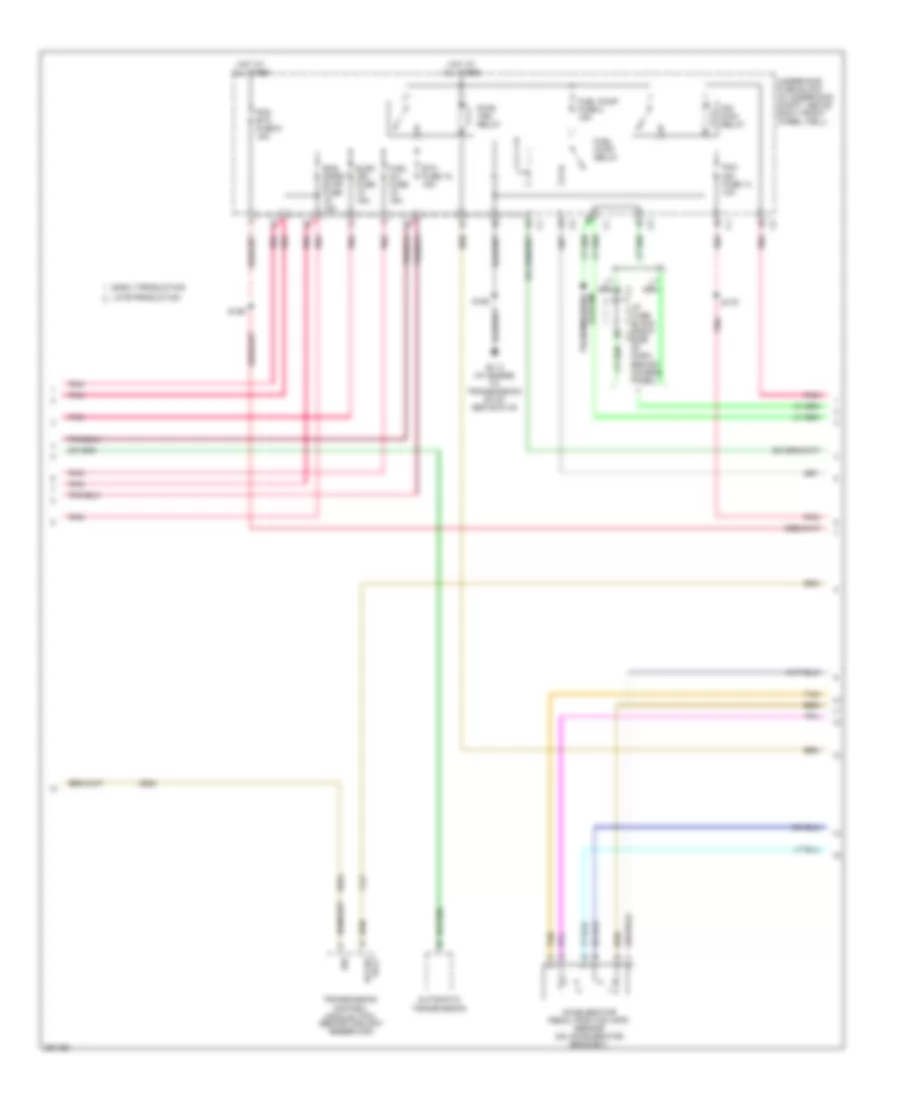
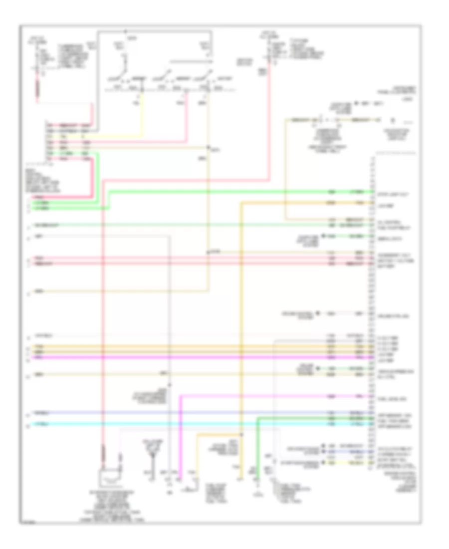
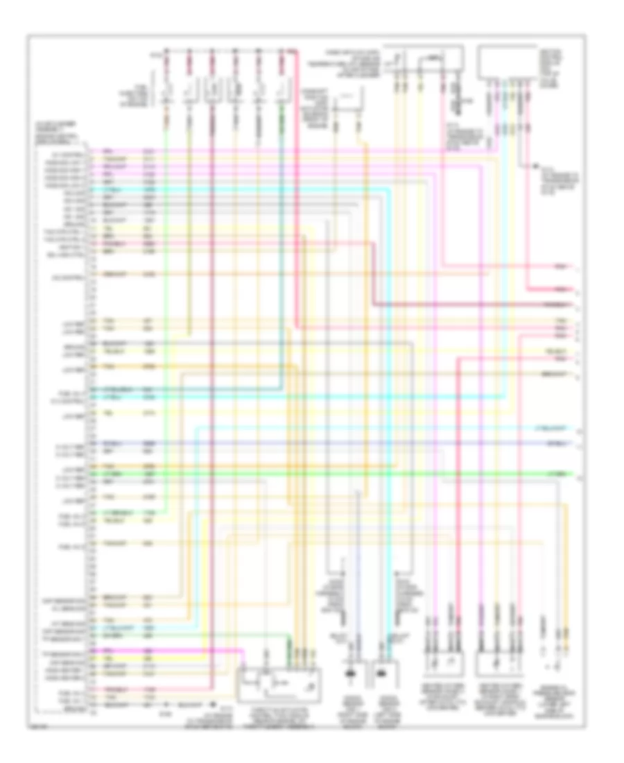
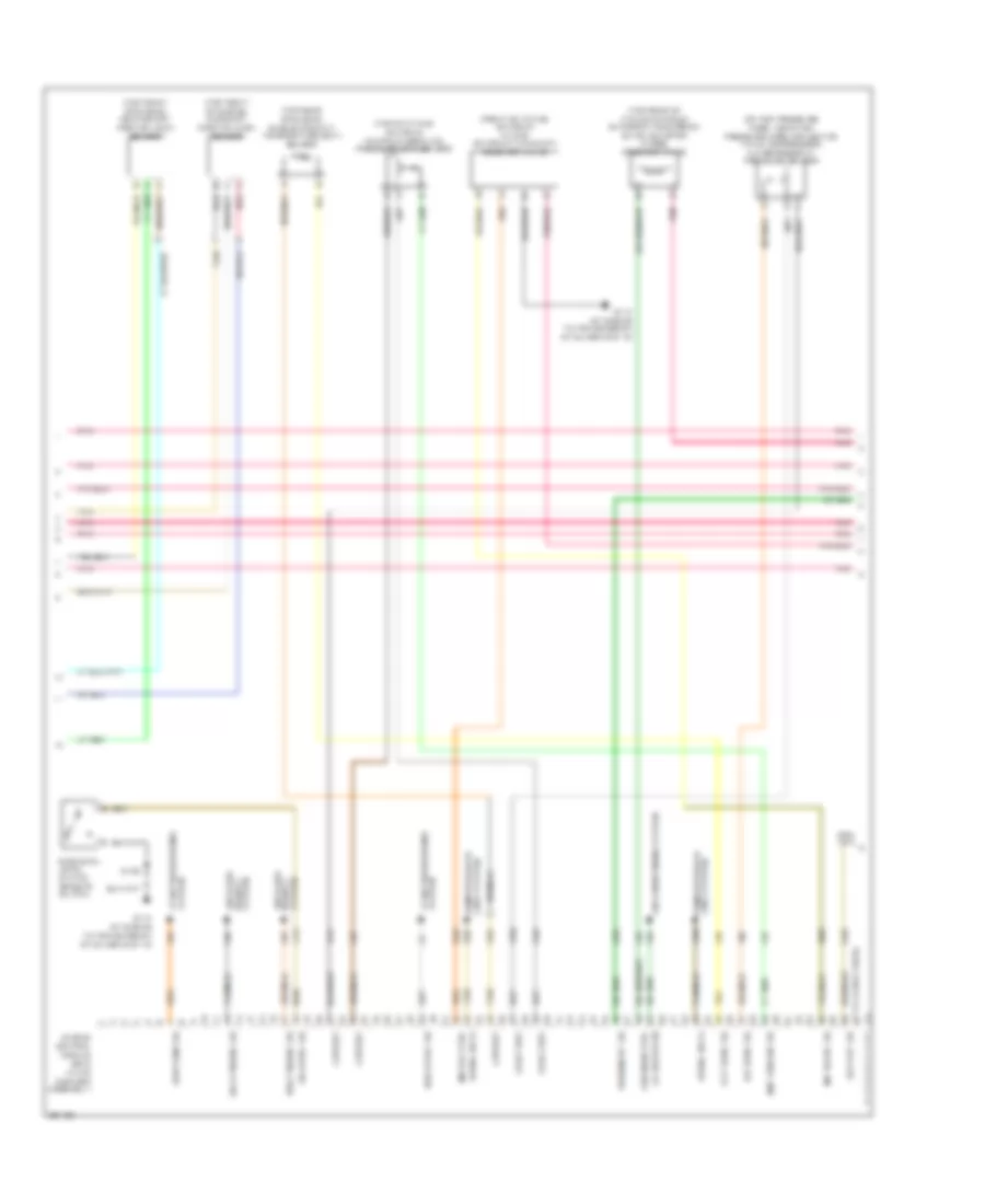
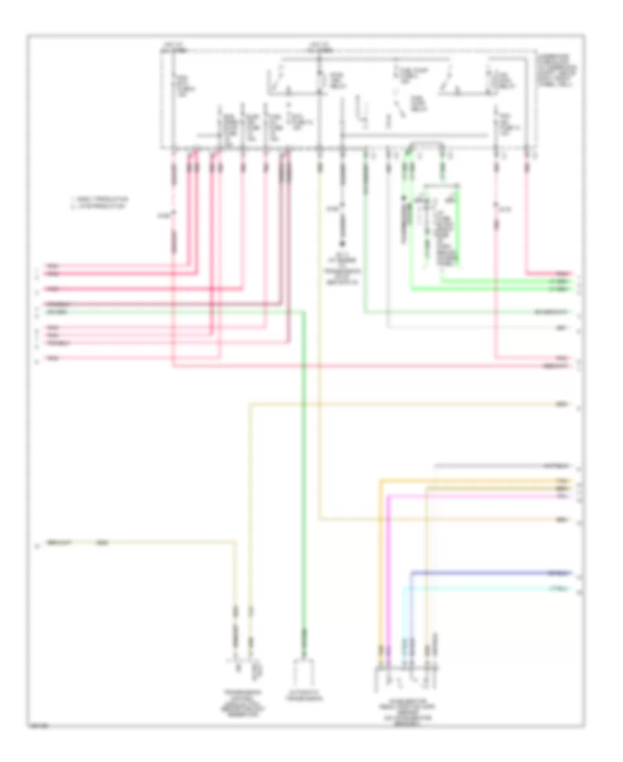
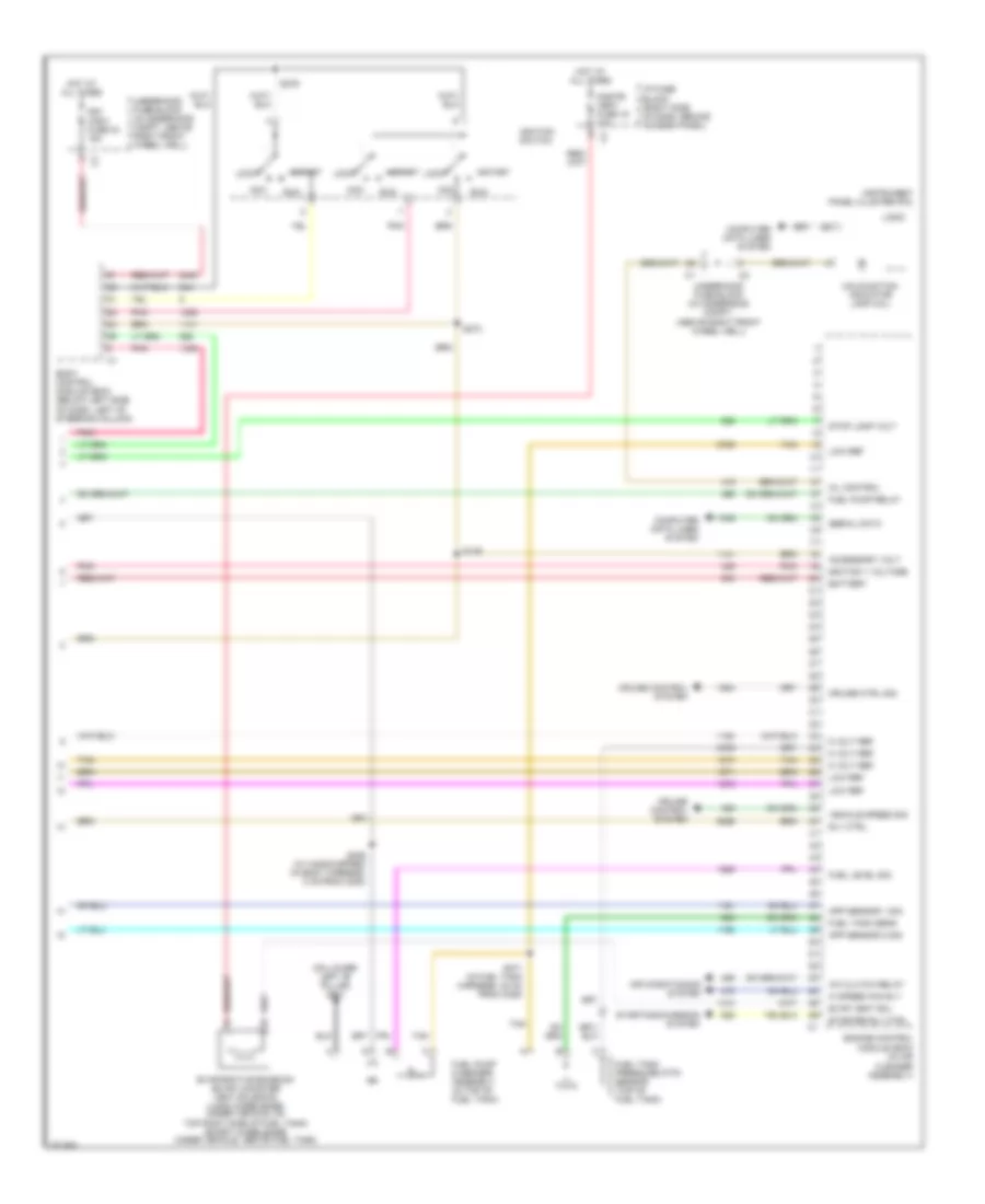
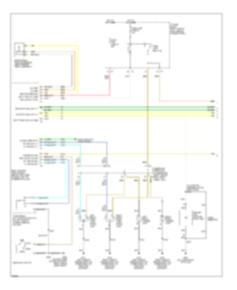
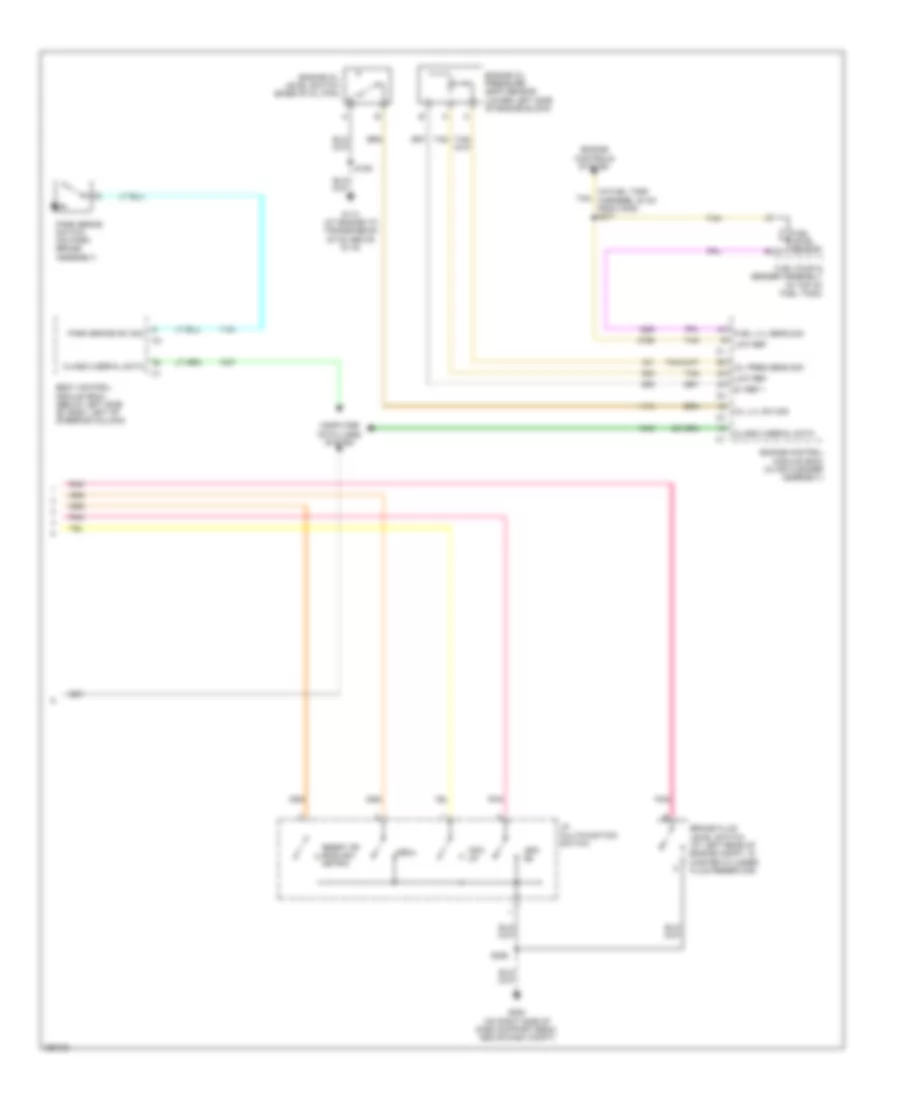
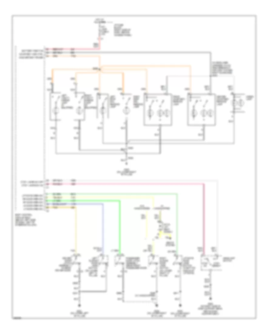
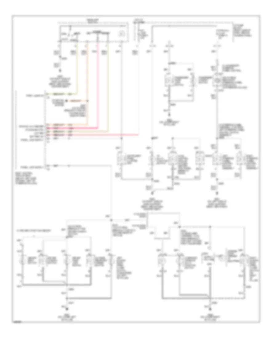
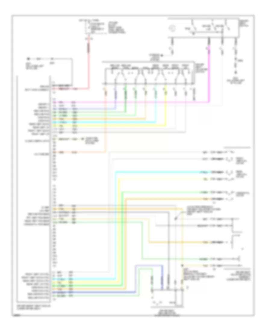
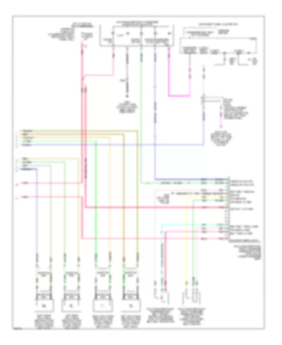
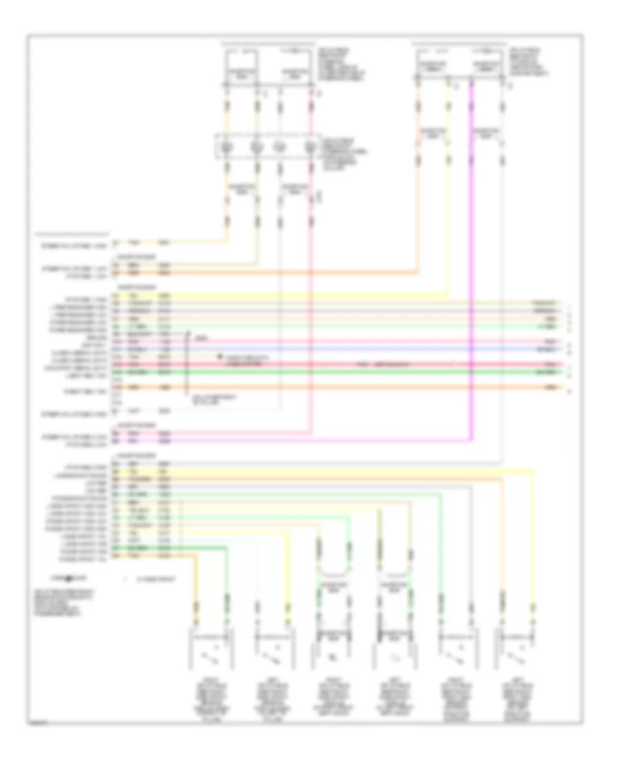
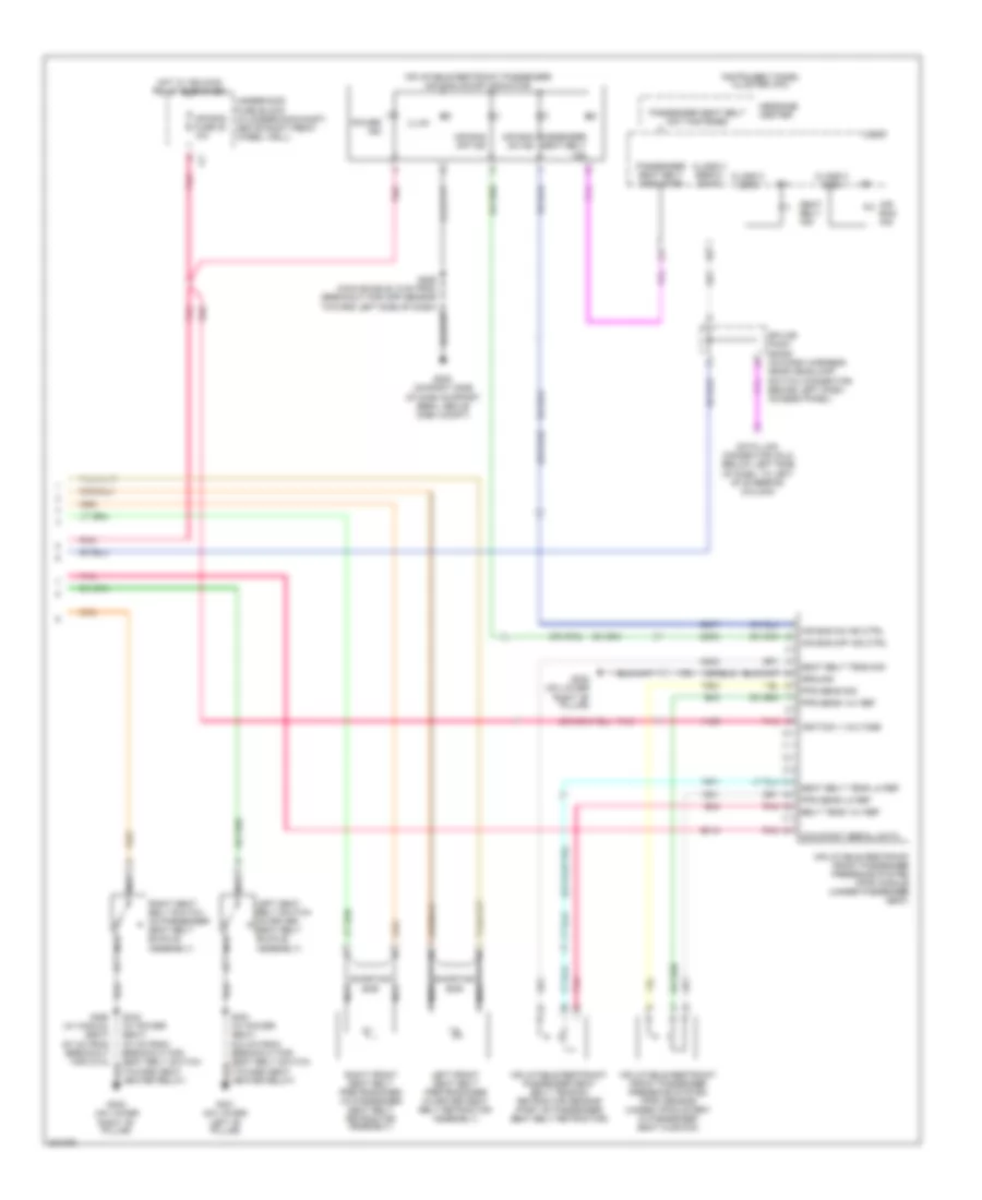
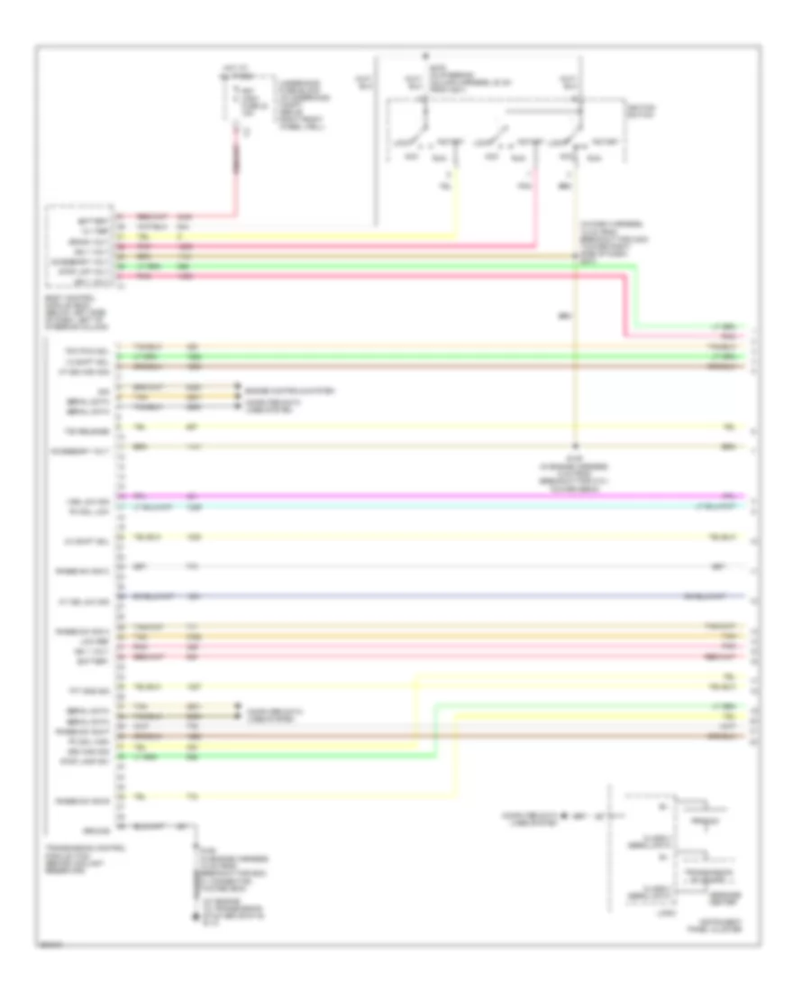
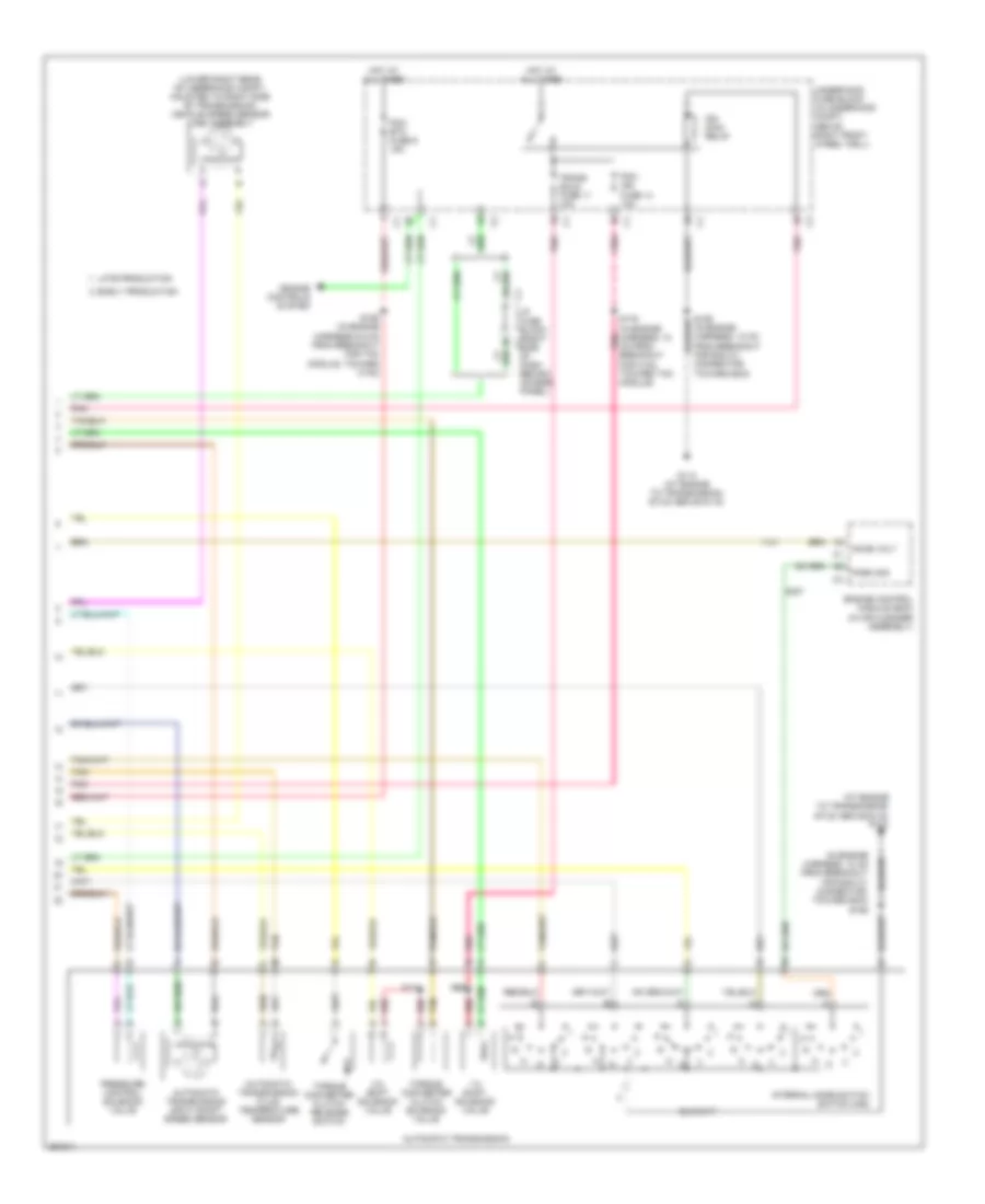
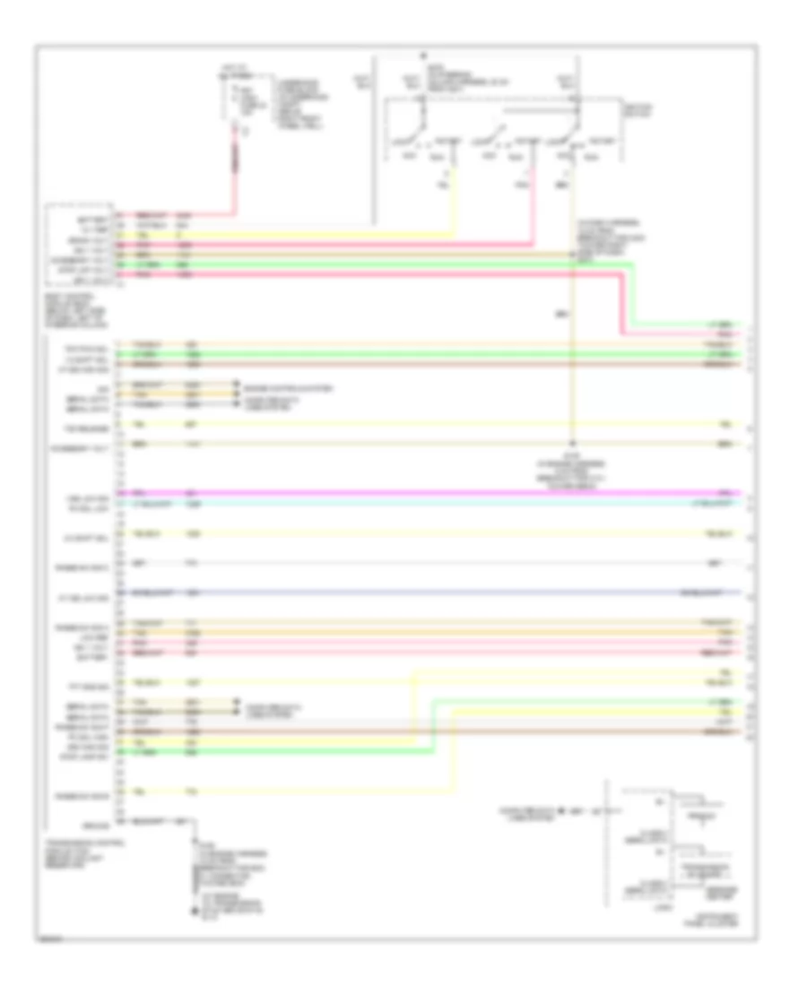
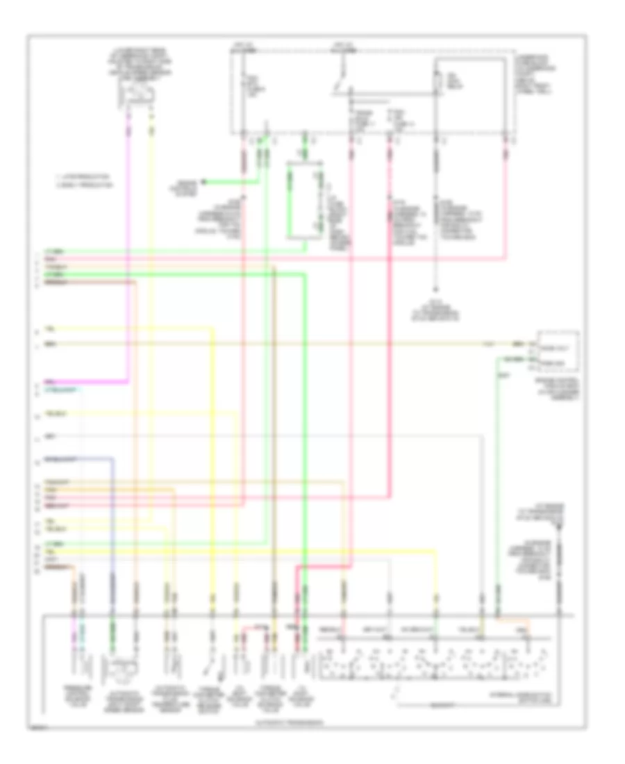
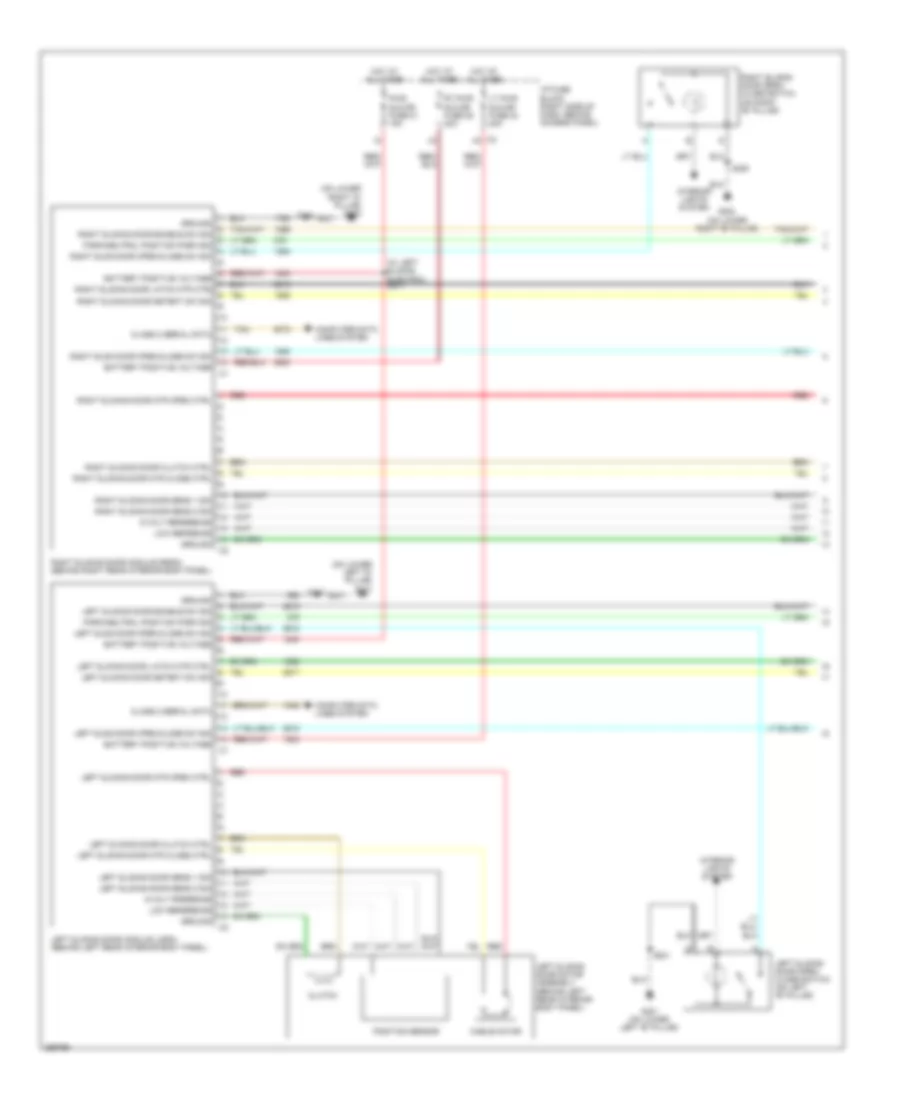
Diagram sections — 31 (73 total)
AIR CONDITIONING ANTI-LOCK BRAKES ANTI-THEFT BODY CONTROL MODULES COMPUTER DATA LINES COOLING FAN CRUISE CONTROL DEFOGGERS ELECTRONIC SUSPENSION ENGINE PERFORMANCE EXTERIOR LIGHTS GROUND DISTRIBUTION HEADLIGHTS HORN INSTRUMENT CLUSTER INTERIOR LIGHTS MEMORY SYSTEMS NAVIGATION POWER DISTRIBUTION POWER DOOR LOCKS POWER MIRRORS POWER SEATS POWER WINDOWS RADIO SHIFT INTERLOCK STARTING/CHARGING SUPPLEMENTAL RESTRAINTS TRANSMISSION TRUNK, TAILGATE, FUEL DOOR WARNING SYSTEMS WIPER/WASHER
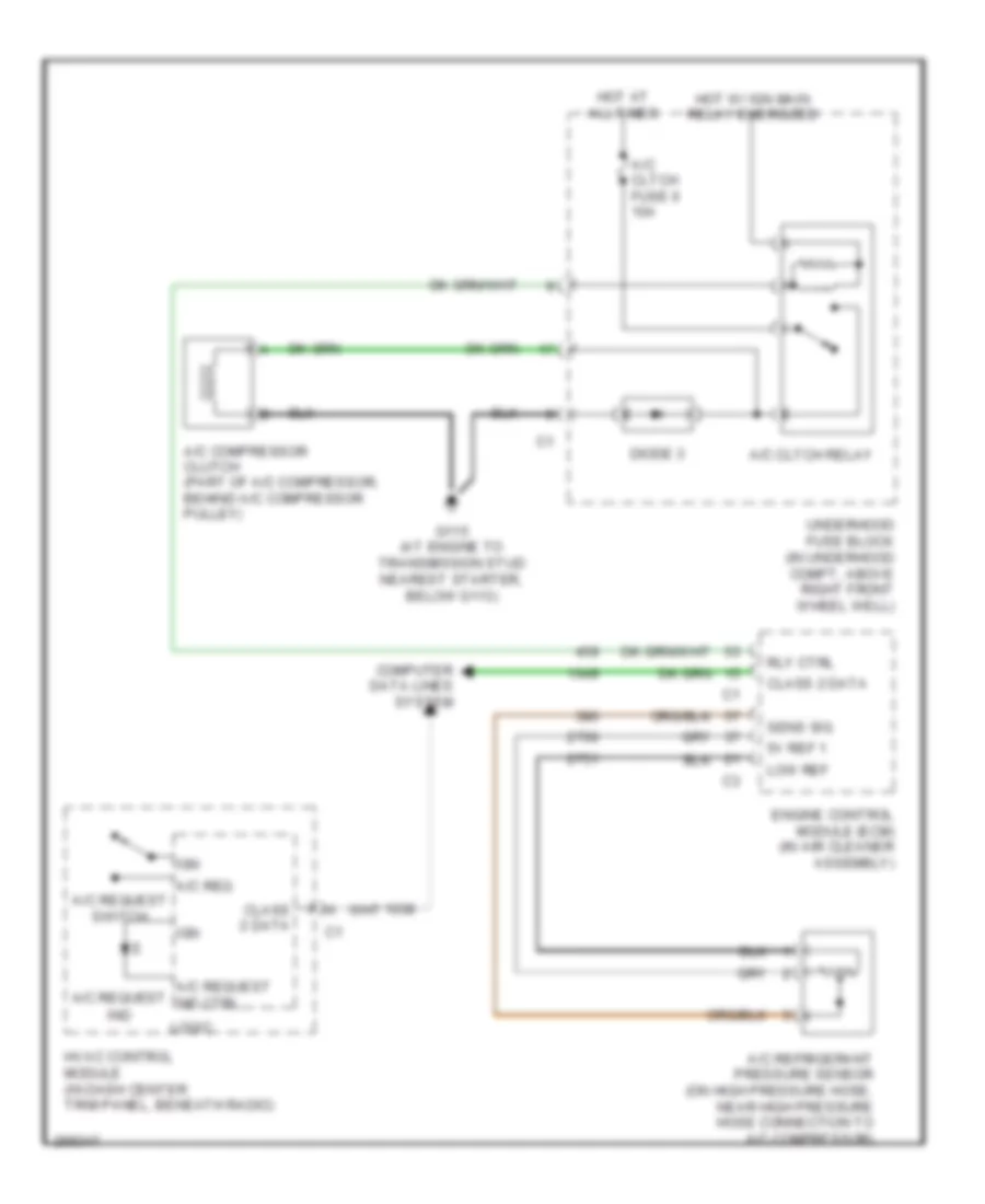
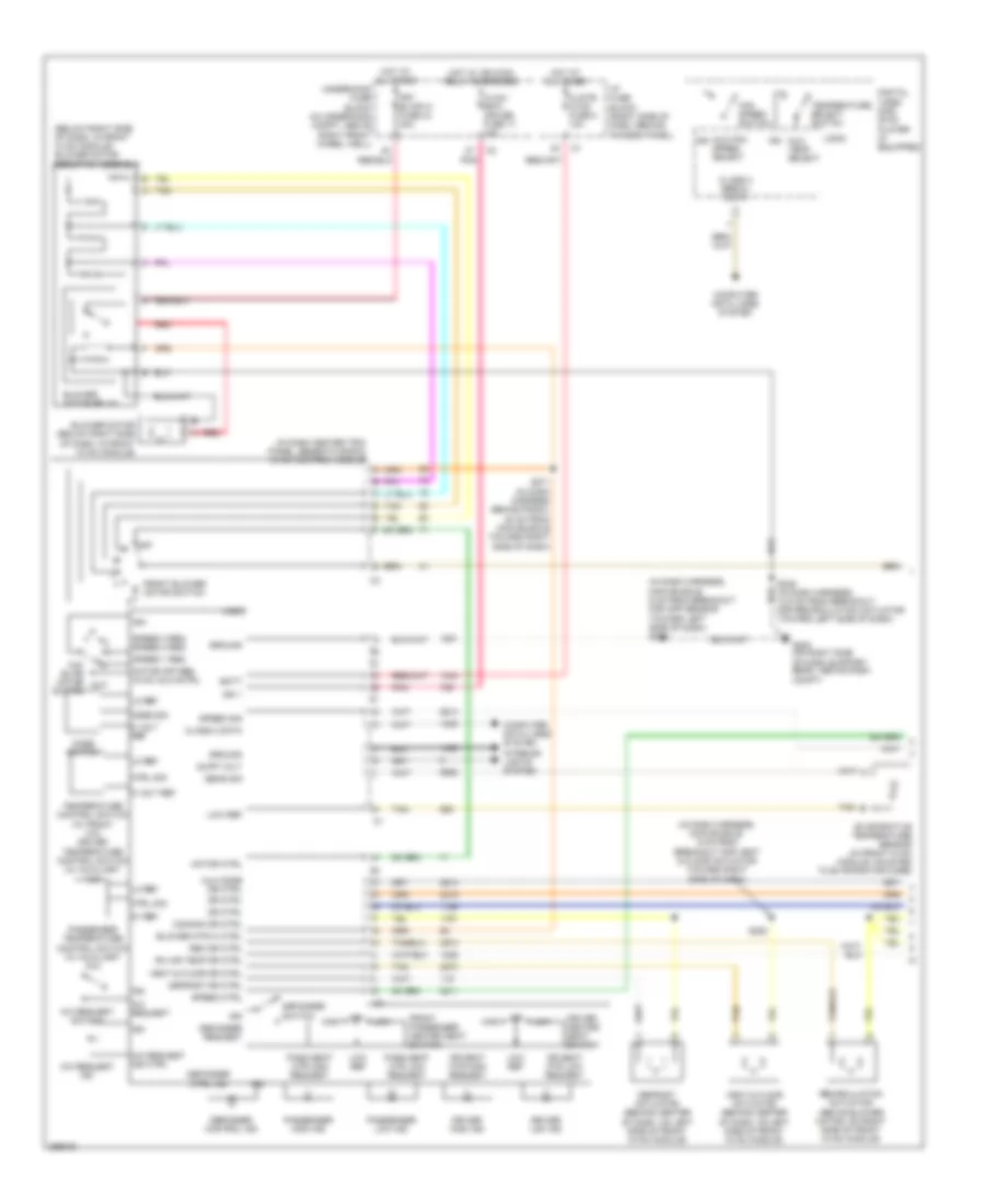
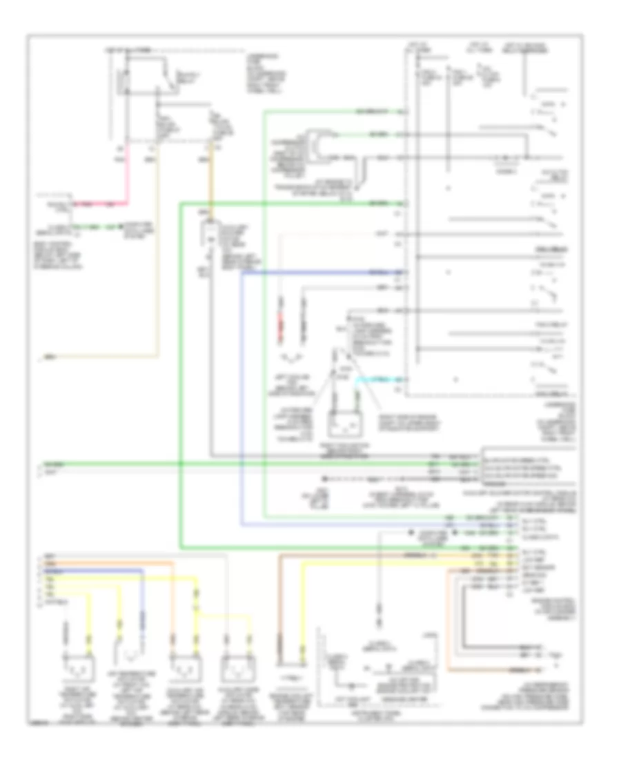
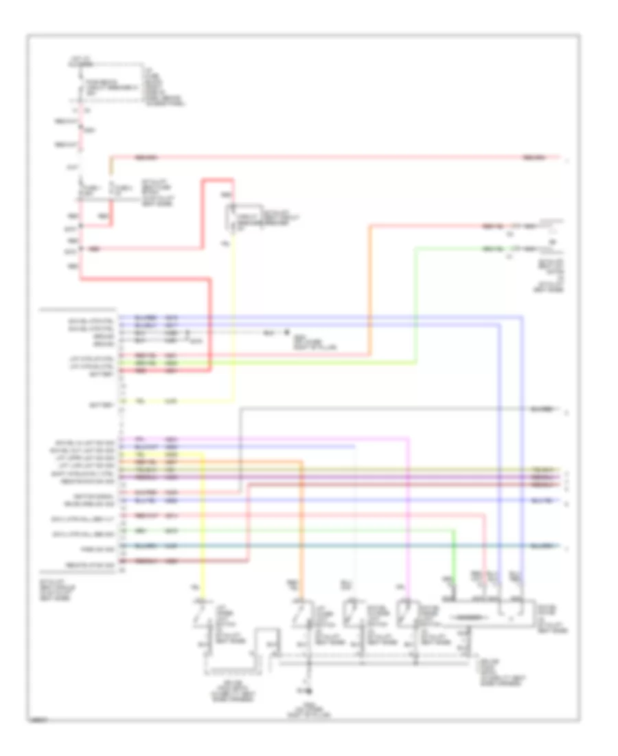
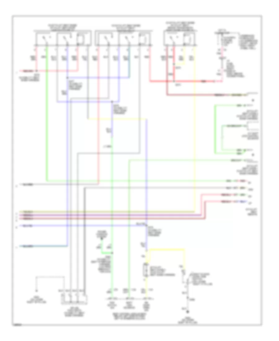
AIR CONDITIONING Compressor Wiring Diagram for Chevrolet Uplander LS 2007 List of elements for Compressor Wiring Diagram for Chevrolet Uplander LS 2007: 24 5v ref 1 A/c cltch fuse 6 10a A/c cltch relay A/c compressor clutch (part of a/c compressor, behind a/c compressor pulley) A/c refrigerant pressure sensor (on high pressure hose, near high pressure hose connection to a/c compressor) A/c req A/c request A/c request ind ctrl A/c request switch Class 2 data Computer data lines system Diode 3 Engine control module (ecm) (in air cleaner assembly) G115 (at engine to transmission stud nearest starter, below g113) Hot at all times Hot w/ ign main relay energized Hvac control module (in dash center trim panel, beneath radio) Ign Ind Logic Low ref Rly ctrl Sens sig Underhood fuse block (in underhood compt, above right front wheel well) Manual A/C Wiring Diagram (1 of 2) for Chevrolet Uplander LS 2007 List of elements for Manual A/C Wiring Diagram (1 of 2) for Chevrolet Uplander LS 2007: 88 (below right side of dash, in front hvac module) blower motor resistor assembly (in dash center trim panel, beneath radio) hvac control module (in dash harness, main bundle, 9 cm from breakout for app sensor toward left side of dash) s255 (in dash harness, main bundle, 9 cm from breakout for vent & floor actuator toward right side of dash) 5 volt ref 5v ref A/c request A/c request ind A/c request ind ctrl A/c request switch Aux Aux blwr motor switch Aux fan speed select Aux mode dr ctrl Aux temp select B b Batt Blower motor (below right side of dash, in front hvac module) Blower motor relay Blower mtr hi ctrl Class 2 data Class 2 serial data Clstr/ hvac fuse 8 10a Commom dr ctrl Computer data lines system Ctrl sig Defogger control ind Defogger ctrl ind Defogger request Defogger switch Defrost actuator (behind center of dash, on left side of front hvac module) Defrost dr ctrl Digital video disc (dvd) player (if equipped) Dr ctrl Dr seat htr high request Dr seat htr low request Driver heated seat switch Driver high ind Driver low ind Evaporative temperature sensor (in front hvac module, mounted to evaporator core) Fan speed switch Front blower motor switch Front passenger heated seat switch Frt blwr hi fuse 34 40a G200 (on right side of dash support beam, above dash compt) Ground High Hot at all times Hot w/ ign main relay energized Hvac/ rpa/ cruise fuse 17 10a I/p fuse block (right side of dash, behind access panel) Ign Ign 1 Interior lights system Lo ref Logic Low Low ref Mode sig Mode switch Motor ctrl Motor off req hvac aux cntrl Off Pass seat htr high request Pass seat htr low request Passenger high ind Passenger low ind Passenger temperature control switch (w/ auxiliary a/c) Pnk Rec dr ctrl Recirculation actuator (above blower motor, on right side of front hvac module) Red Rh air temp dr ctrl S246 (in dash harness, 12.5 cm from breakout for recirculation actuator toward left side of dash) S253 S271 (in dash harness behind radio, 20 cm from main bundle toward right side of dash) Sens sig Speed 1 req Speed 3 req speed 2 req Speed ctrl Speed sig Supp volt Tan Temperature control switch (w/ front a/c) driver temperature control switch (w/ auxiliary a/c) Temperature select switch Underhood fuse block (in underhood compt, above right front wheel well) Vent & floor actuator (behind center of dash, on left side of front hvac module) Vent & floor dr ctrl Manual A/C Wiring Diagram (2 of 2) for Chevrolet Uplander LS 2007 List of elements for Manual A/C Wiring Diagram (2 of 2) for Chevrolet Uplander LS 2007: 59 (at engine to transmission stud nearest starter, below g113) g115 (in forward lamp harness, 6 cm from breakout for c104 toward c110) (right side of engine compt on upper front of radiator support) 5v ref 1 A/c cltch fuse 6 10a A/c cltch relay A/c compressor clutch (part of a/c compressor, behind a/c compressor pulley) A/c off for engine protection engine coolant hot A/c refrigerant pressure sensor (on high pressure hose, near high pressure hose connection to a/c compressor) Air temperature actuator (w/ front a/c) left air temperature actuator (w/ auxiliary a/c) (behind center of dash) Aux blwr motor speed ctrl Aux blwr motor speed sig Auxiliary air temperature actuator (w/ rear a/c) (behind left rear interior body panel) Auxiliary blower motor (w/ rear a/c) (behind left rear interior body panel) Auxiliary blower motor control module (w/ rear a/c) (in rear hvac module, behind left rear interior body panel) Auxiliary mode actuator (w/ rear a/c) (in rear hvac module, behind left rear interior body panel) Blwr motor speed ctrl Body control module (bcm) (below left side of dash, left of steering column) Class 2 Class 2 data Class 2 serial data Computer data lines system Ctrl Diode 3 Ect sensor Engine control module (ecm) (in air cleaner assembly) Engine coolant temperature (ect) sensor (top rear of engine) Fan 1 fuse 29 30a Fan 1 relay Fan 2 fuse 33 40a Fan 2 relay Fan 3 relay Frt/ blwr fuse 27 25a G100 G401 (on lower left "d" pillar) Ground Hot at all times Hot coolant ind Hot w/ ign main relay energized Instrument panel cluster (ipc) Left cooling fan (behind left side of radiator) Logic Low ref Message center Pnk Red Right air temperature actuator (w/ auxiliary a/c) (right side hvac module) Right cooling fan (behind right side of radiator) Rly ctrl Rr blwr/ 110vac fuse 26 25a Run rly Run rly relay S102 (in forward lamp harness, 6.5 cm from breakout for g100, toward c110) S106 S413 (in body harness, 6.5 cm from breakout for c479 toward left "c" pillar) Sens sig Serial data c1 Tan Underhood fuse block (in underhood compt, above right front wheel well)
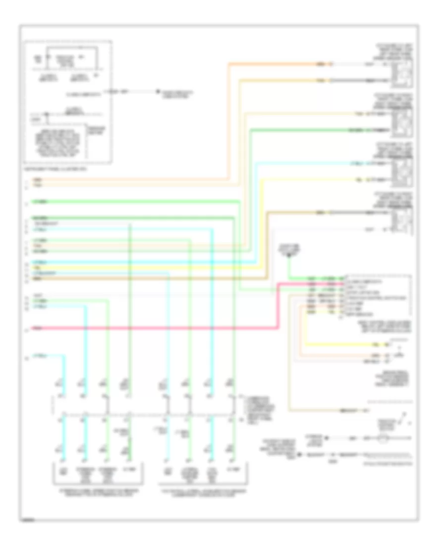
ANTI-LOCK BRAKES Anti-lock Brakes Wiring Diagram (1 of 2) for Chevrolet Uplander LS 2007 List of elements for Anti-lock Brakes Wiring Diagram (1 of 2) for Chevrolet Uplander LS 2007: 52 (on left strut tower) electronic brake control module (ebcm) 5v ref Abs fuse 13 10a Abs motor fuse 31 60a Brake pressure modulator valve (bpmv) Class 2 ser data Computer data lines system Del torque sig Early production Engine control module (ecm) (in air cleaner assembly) G113 (at engine to transmission stud above g115) G115 (at engine to transmission stud nearest starter, below g113) Ground Hot at all times I/p fuse block (right side of dash, behind access panel) Ign 1 volt Ign main relay Late production Lateral accelerometer signal Left front inlet Left front iso- lation (w/ tcs) Left front outlet Left front prime (w/ tcs) Left rear inlet Left rear outlet Lf wheel speed sens low ref Lf wheel speed sens sig Low ref Lr wheel speed sens low ref Lr wheel speed sens sig Pnk Pump motor Pump motor control Req torque sig Rf wheel spd sens sig Rf wheel speed sens low ref Right front inlet Right front iso- lation (w/ tcs) Right front outlet Right front prime (w/ tcs) Right rear inlet Right rear outlet Rr wheel spd sens sig Rr whl spd sen low ref S155 Sol vlv ctrl Solenoid valves Steering wheel pos sig a Steering wheel pos sig b Tan Underhood fuse block (in underhood compartment, above right front wheel well) Yaw rate sen sig Anti-lock Brakes Wiring Diagram (2 of 2) for Chevrolet Uplander LS 2007 List of elements for Anti-lock Brakes Wiring Diagram (2 of 2) for Chevrolet Uplander LS 2007: 38 (attached to left front wheel hub) left front wheel speed sensor (wss) (attached to left rear wheel hub) (attached to right front wheel hub) right front wheel speed sensor (wss) (attached to right rear wheel hub) right rear wheel speed sensor (wss) (on right side of dash support beam, above dash compartment) g200 10v ref 5v ref Abs ind Body control module (bcm) (below left side of dash, left of steering column) Bpp sens sig Brake pedal position sensor (above brake pedal assembly) C1 underhood fuse block (in underhood compartment, above right front wheel c2 Class 2 ser data Computer data lines system I/p multifunction switch Ign 1 volt Instrument panel cluster (ipc) Interior lights system Lateral acceler- ometer sig Left rear wheel speed sensor (wss) Logic Low ref Message center Nca Pnk S255 Service abs sys service stability sys service traction sys stability ctrl active stability ctrl off traction ctrl active traction ctrl off Steering wheel pos sig a Steering wheel pos sig b Steering wheel speed position sensor (near bottom of steering column) Stop lmp sw sig Tan Traction control off ind Traction control switch Traction control switch sig Well) Yaw rate & lateral acceleration sensor (under front console on floor) Yaw rate sen sig
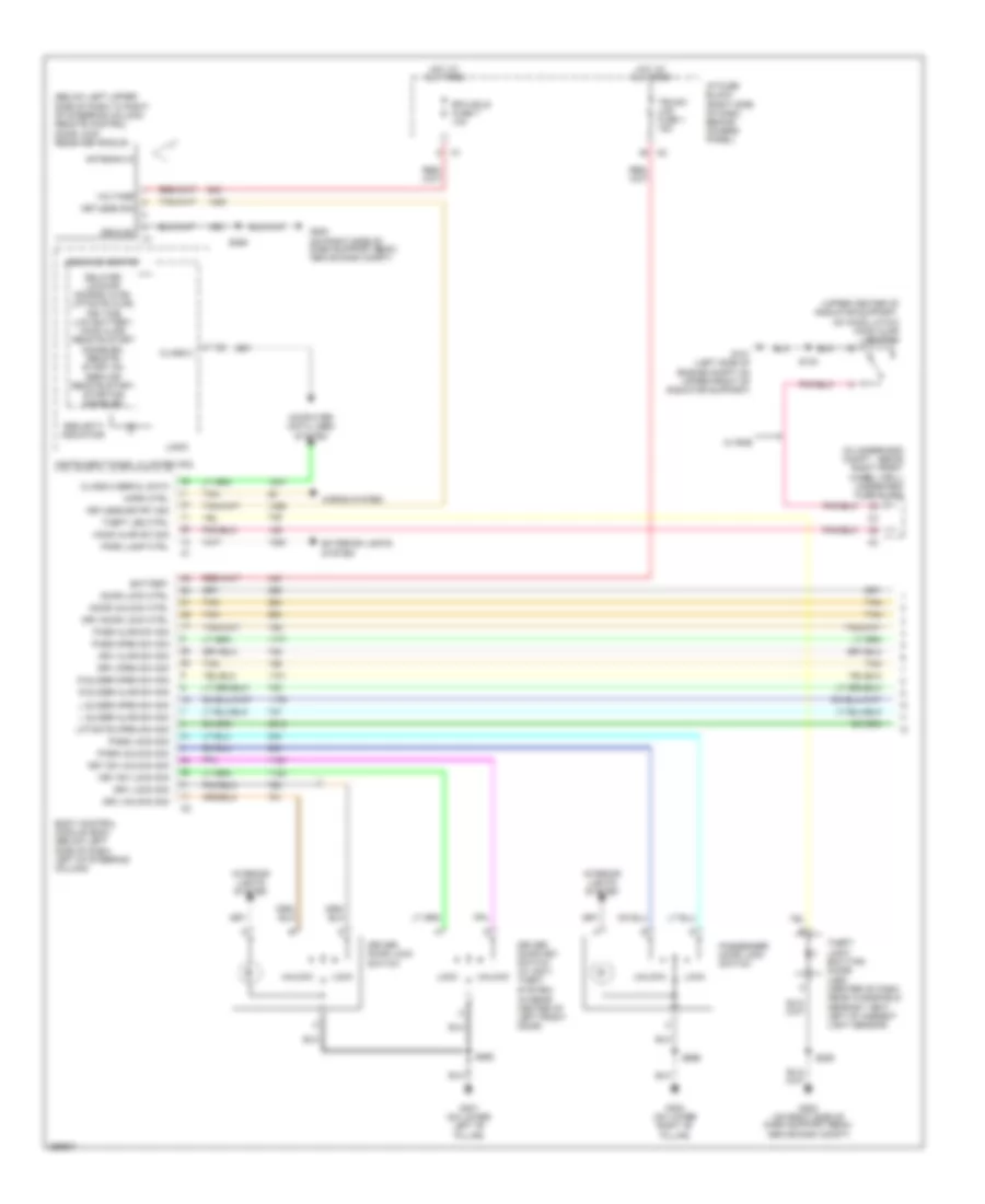
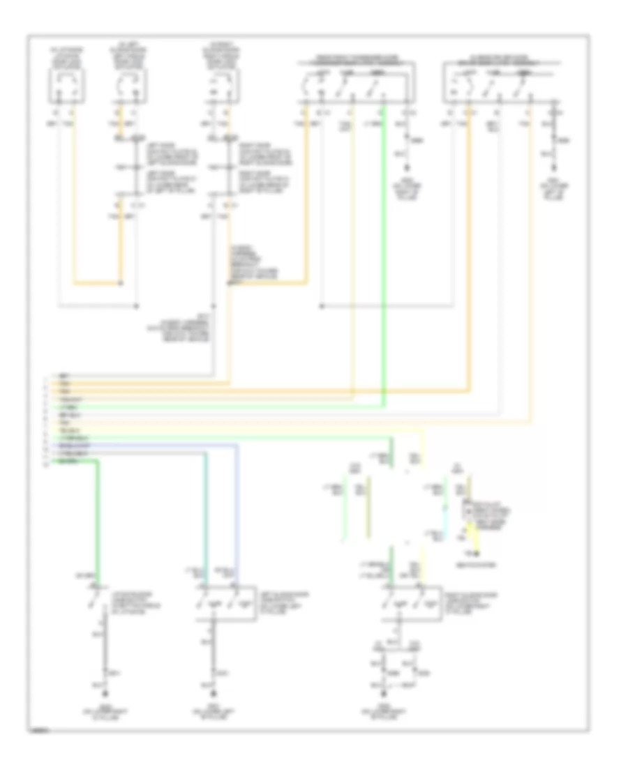
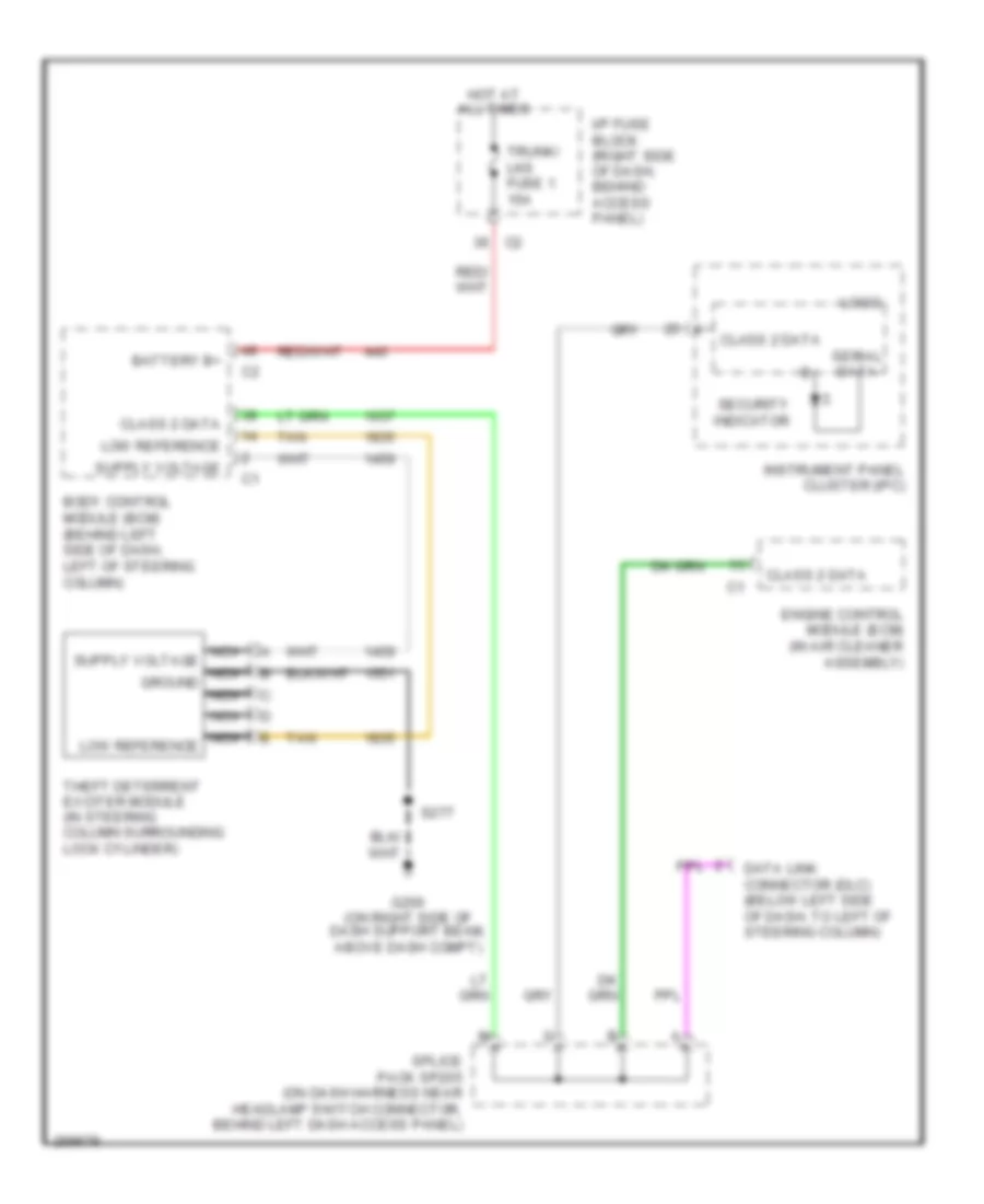
ANTI-THEFT Forced Entry Wiring Diagram (1 of 2) for Chevrolet Uplander LS 2007 List of elements for Forced Entry Wiring Diagram (1 of 2) for Chevrolet Uplander LS 2007: 64 (below left upper side of dash to right of steering column) remote control door lock receiver (rcdlr) (in rear center of left front door) (in underhood compt, above right front wheel well) underhood fuse block (upper center of radiator support, on hood latch) hood ajar switch Antenna in Battery Body control module (bcm) (below left side of dash, left of steering column) Class 2 Class 2 serial data Computer data lines system Delayed locking, door(s) ajar, liftgate ajar, key fob low battery, hood ajar, remote start disabled, remote start on, service remote start, starting disabled Door lock ctrl Door unlock ctrl Driver door key switch (w/ anti- theft system) Driver door lock switch Drv ajar sw sig Drv door lock ctrl Drv lock sig Drv open sw sig Drv unlock sig Exterior lights system G101 (left side of engine compt on upper front of radiator support) G200 (on right side of dash support beam, above dash compt) G301 (on lower left "b" pillar) G302 (on lower right "b" pillar) Ground Hood ajar sw sig Horn ctrl Horns system Hot at all times I/p fuse block (right side of dash, behind access panel) Instrument panel cluster (ipc) Interior lights system Key sw lock sig Key sw unlock sig Keyless entry sig Keyless sig L slider ajar sw sig L slider open sw sig Liftgate open sw sig Lock Logic Message center Park lamp ctrl Pass ajar sw sig Pass lock sig Pass open sw sig Pass unlock sig Passenger door lock switch R slider ajar sw sig R slider open sw sig Rfa mdls fuse 7 10a S103 S255 S555 S666 Security indicator Tan Theft led ctrl Theft light emitting diode (led) (center of dash, near windshield defrost vent, left of ambient light sensor) Trunk/ lks fuse 1 15a Unlock Voltage W/ rke Forced Entry Wiring Diagram (2 of 2) for Chevrolet Uplander LS 2007 List of elements for Forced Entry Wiring Diagram (2 of 2) for Chevrolet Uplander LS 2007: 40 "d" pillar) (in body harness, 5.5 cm from breakout for c313 toward rear of vehicle) s311 (in left sliding door) left middle door lock actuator (in liftgate) liftgate door lock actuator (in rear driver door) driver door latch assembly (in right sliding door) right middle door lock actuator (rear front passenger door) passenger door latch assembly A c2 Ajar B c1 B c2 C1 a C1 b C2 a C2 d Ctsy G301 (on lower left "b" pillar) G302 (on lower right "b" pillar) G400 (on lower right Left door contact plate c1 (in lower rear of left "b" pillar) Left door contact plate c2 (in lower front of left sliding door) Left sliding door jamb switch (on lower left "c" pillar) Liftgate door jamb switch (in bottom middle of liftgate) Lock Open Right door contact plate c1 (in lower rear of right "b" pillar) Right door contact plate c2 (in lower front of right sliding door) Right sliding door jamb switch (on lower right "c" pillar) S313 (in body harness, 23.5 cm from breakout for c313 toward rear of vehicle) S320 S331 S366 S555 S666 S911 Seats system Sit-n-lift seat diode 3 (in sit-n-lift seat base harness) Tan W/ aqw W/o aqw Pass-Key Wiring Diagram for Chevrolet Uplander LS 2007 List of elements for Pass-Key Wiring Diagram for Chevrolet Uplander LS 2007: 21 Battery b+ Body control module (bcm) (behind left side of dash, left of steering column) Class 2 data Data link connector (dlc) (below left side of dash, to left of steering column) Engine control module (ecm) (in air cleaner assembly) G200 (on right side of dash support beam, above dash compt) Hot at all times I/p fuse block (right side of dash, behind access panel) Instrument panel cluster (ipc) Logic Low reference Nca Nca ground Nca low reference S277 Security indicator Serial data Splice pack sp205 (on dash harness near headlamp switch connector, behind left dash access panel) Tan Theft deterrent exciter module (in steering column surrounding lock cylinder) Trunk/ lks fuse 1 15a
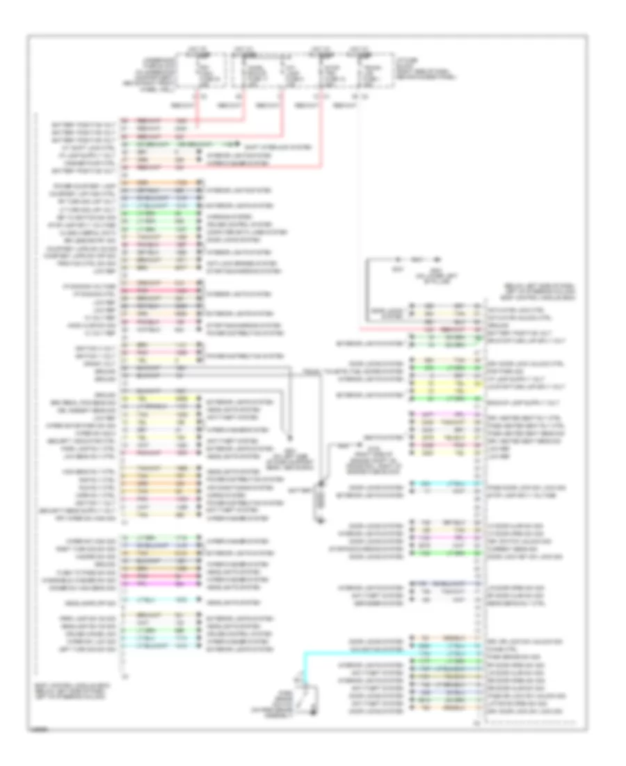
BODY CONTROL MODULES
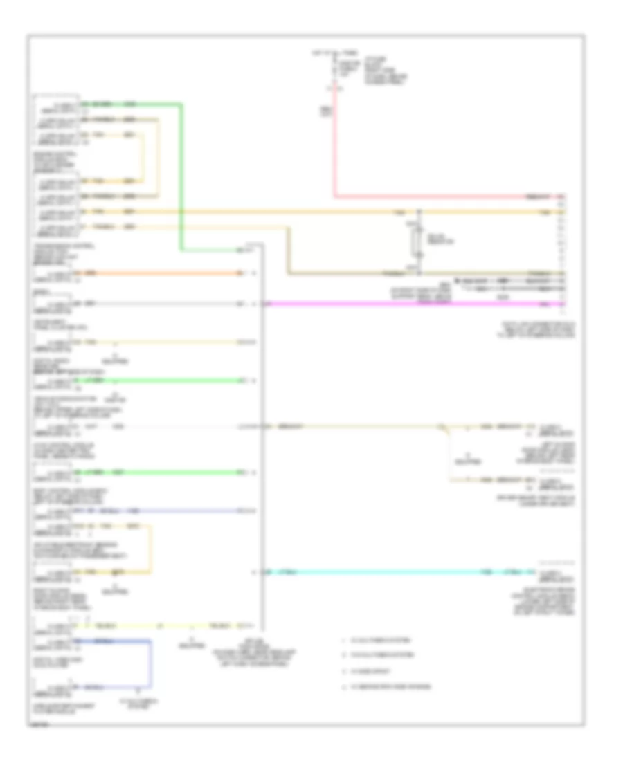
COMPUTER DATA LINES Computer Data Lines Wiring Diagram for Chevrolet Uplander LS 2007 List of elements for Computer Data Lines Wiring Diagram for Chevrolet Uplander LS 2007: 37 A11 A12 Body control module (bcm) (below left side of dash, left of steering column) Class 2 serial data Data link connector (dlc) (below left side of dash, to left of steering column) Digital radio receiver (behind left side of dash) Digital video disc (dvd) player Driver memory seat module (under driver seat) Electronic brake control module (ebcm) (lower left side of engine compartment, on left strut tower) Engine control module (ecm) (in air cleaner assembly) G200 (on right side of dash support beam, above dash compt) Gmlan resistor Hi spd gmlan serial data + Hi spd gmlan serial data - Hot at all times Hvac control module (in dash center trim panel, beneath radio) I/p fuse block (right side of dash, behind access panel) If equipped Inflatable restraint sensing & diagnostic module (sdm) (on floor below passenger seat) Instrument panel cluster (ipc) Left sliding door module (lsdm) (behind left rear interior body panel) Mobile entertainment player module Nca Onstar fuse 6 10a Radio Right sliding door module (rsdm) (behind right rear interior body panel) S246 S255 Splice pack sp205 (on dash harn, near headlamp switch connector, behind left dash access panel) Tan Transmission control module (tcm) (behind coolant reservoir) Vehicle communication unit (vcu) (behind upper left side of dash, to left of steering column) W/ multimedia system W/ onstar W/ second row side air bags W/ side impact W/o multimedia system
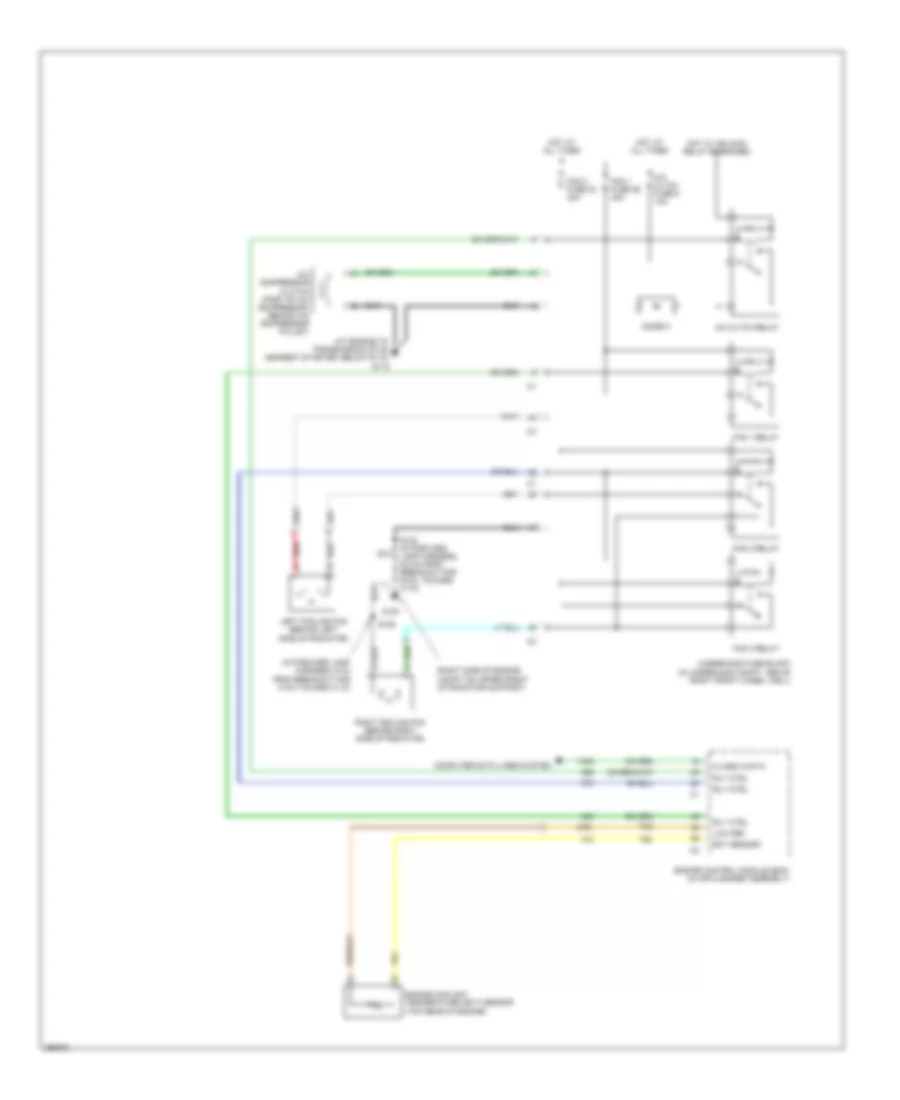
COOLING FAN Cooling Fan Wiring Diagram for Chevrolet Uplander LS 2007 List of elements for Cooling Fan Wiring Diagram for Chevrolet Uplander LS 2007: 30 (at engine to transmission stud nearest starter, below g113) (in forward lamp harness, 6 cm from breakout for c104 toward c110) (right side of engine compt on upper front of radiator support) A/c cltch fuse 6 10a A/c cltch relay A/c compressor clutch (part of a/c compressor, behind a/c compressor pulley) Class 2 data Computer data lines system Diode 3 Ect sensor Engine control module (ecm) (in air cleaner assembly) Engine coolant temperature (ect) sensor (top rear of engine) Fan 1 fuse 29 30a Fan 1 relay Fan 2 fuse 33 40a Fan 2 relay Fan 3 relay G100 G115 Hot at all times Hot w/ ign main relay energized Left cooling fan (behind left side of radiator) Low ref Red Right cooling fan (behind right side of radiator) Rly ctrl S102 (in forward lamp harness, 6.5 cm from breakout for g100, toward c110) S106 Tan Underhood fuse block (in underhood compt, above right front wheel well)
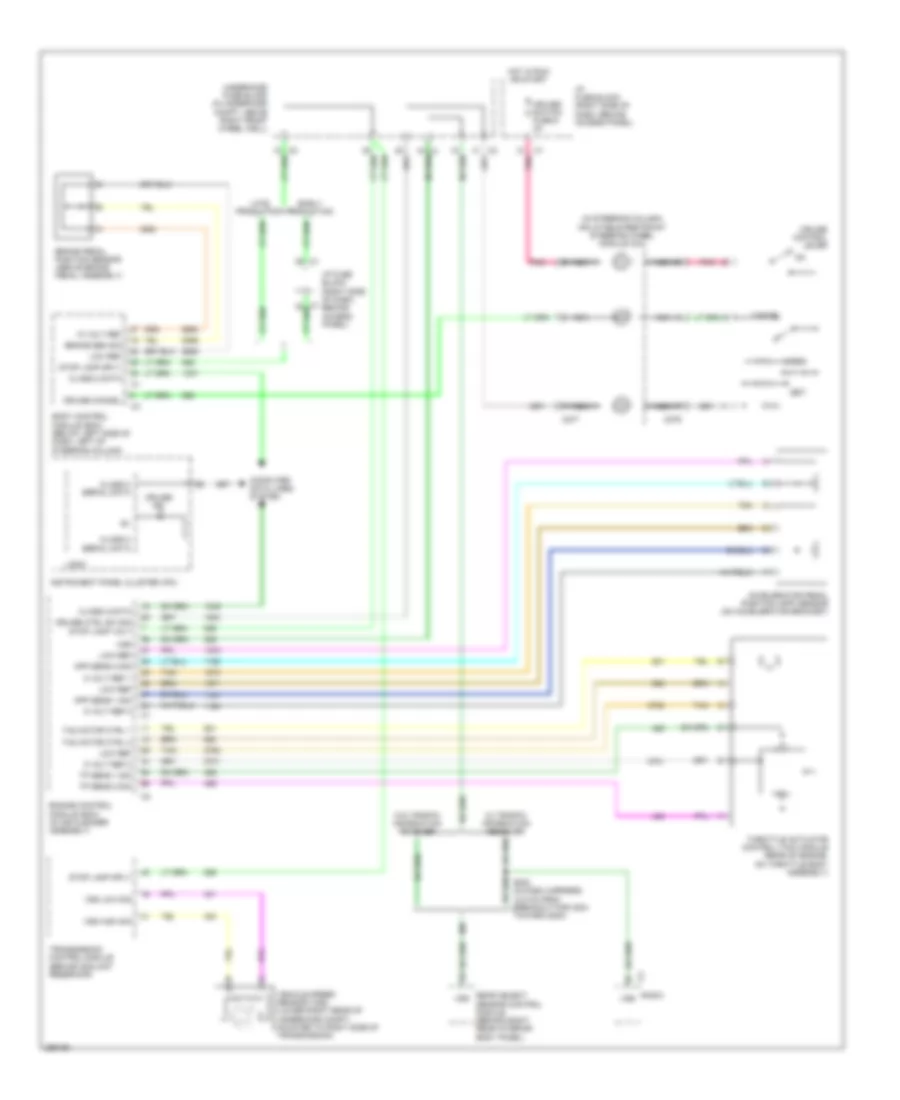
CRUISE CONTROL Cruise Control Wiring Diagram for Chevrolet Uplander LS 2007 List of elements for Cruise Control Wiring Diagram for Chevrolet Uplander LS 2007: 51 (in steering column) inflatable restraint steering wheel module coil 10 volt ref 5 volt ref 1 5 volt ref 2 Accelerator pedal position (app) sensor (on accelerator bracket) App sens 1 sig App sens 2 sig Body control module (bcm) (below left side of dash, left of steering column) Brake pedal position sensor (above brake pedal assembly) Brake sen sig C277 C279 Cancel Class 2 data Class 2 serial data Computer data lines system Cruise cancel Cruise control lever Cruise ctrl sw sig stop lamp volt Cruise ind Cruise/ switch fuse 9 2a Early production Engine control module (ecm) (in air cleaner assembly) Hot in run or start I/p fuse block (right side of dash, behind access panel) Instrument panel cluster (ipc) Late production Logic Low ref Nca Pnk Radio Rear object sensor control module (behind right rear interior body panel) Res+ S202 (in dash harness, 10.5 cm from breakout for c204 toward g200) Set- Stop lamp sply Tac motor ctrl 1 Tac motor ctrl 2 Tan Throttle actuator control (tac) module (rear of engine, on throttle body assembly) Tp sens 1 sig Tp sens 2 sig Transmission control module (behind coolant reservoir) Underhood fuse block (in underhood compt, above right front wheel well) Vehicle speed sensor (vss) (lower right rear of underhood compt, mounted to right side of transmission) Vss Vss high sig Vss low sig W/ traffic information receiver W/o traffic information receiver
DEFOGGERS Defoggers Wiring Diagram for Chevrolet Uplander LS 2007 List of elements for Defoggers Wiring Diagram for Chevrolet Uplander LS 2007: 32 "b" pillar) g301 "b" pillar) g302 (on lower left (on lower right (on lower right "d" pillar) g400 A c1 A c2 Body control module (bcm) (below left side of dash, left of steering column) Class 2 data Class 2 serial data Def indicator control Defogger indicator Defogger request Defogger switch Driver outside rearview mirror Hot at all times Htd/ mir fuse 16 10a Hvac control module (in dash center trim panel, beneath radio) I/p fuse block (right side of dash, behind access panel) Ign Mirror defogger Nca Passenger outside rearview mirror Rear fog relay control Rear window defogger grid Rr defog fuse 36 40a Rr defog relay 30 S555 S666 S911 Splice pack sp205 (on dash harness near headlamp switch connector, behind left dash access panel) Underhood fuse block (in underhood compt, above right front wheel well)
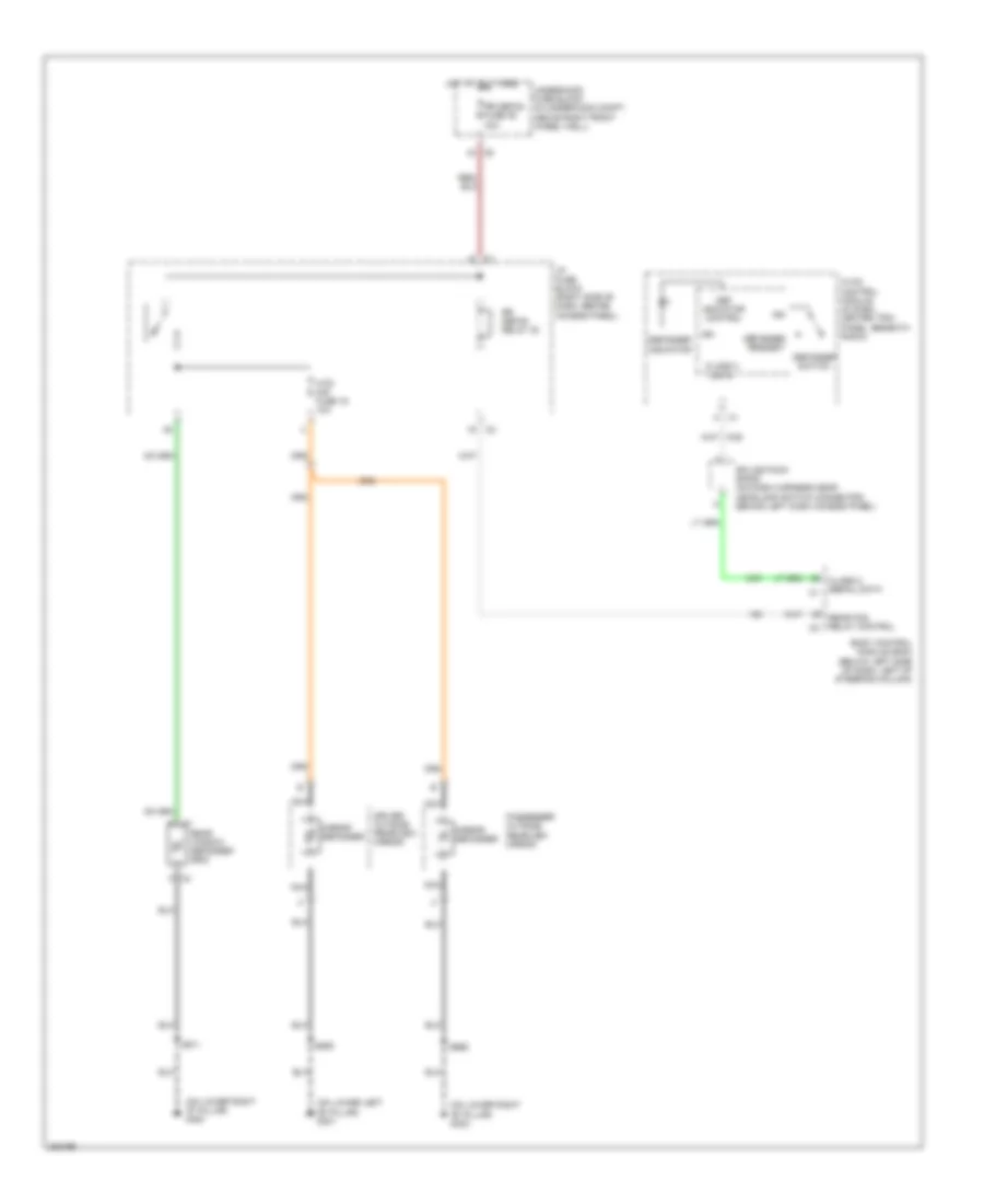
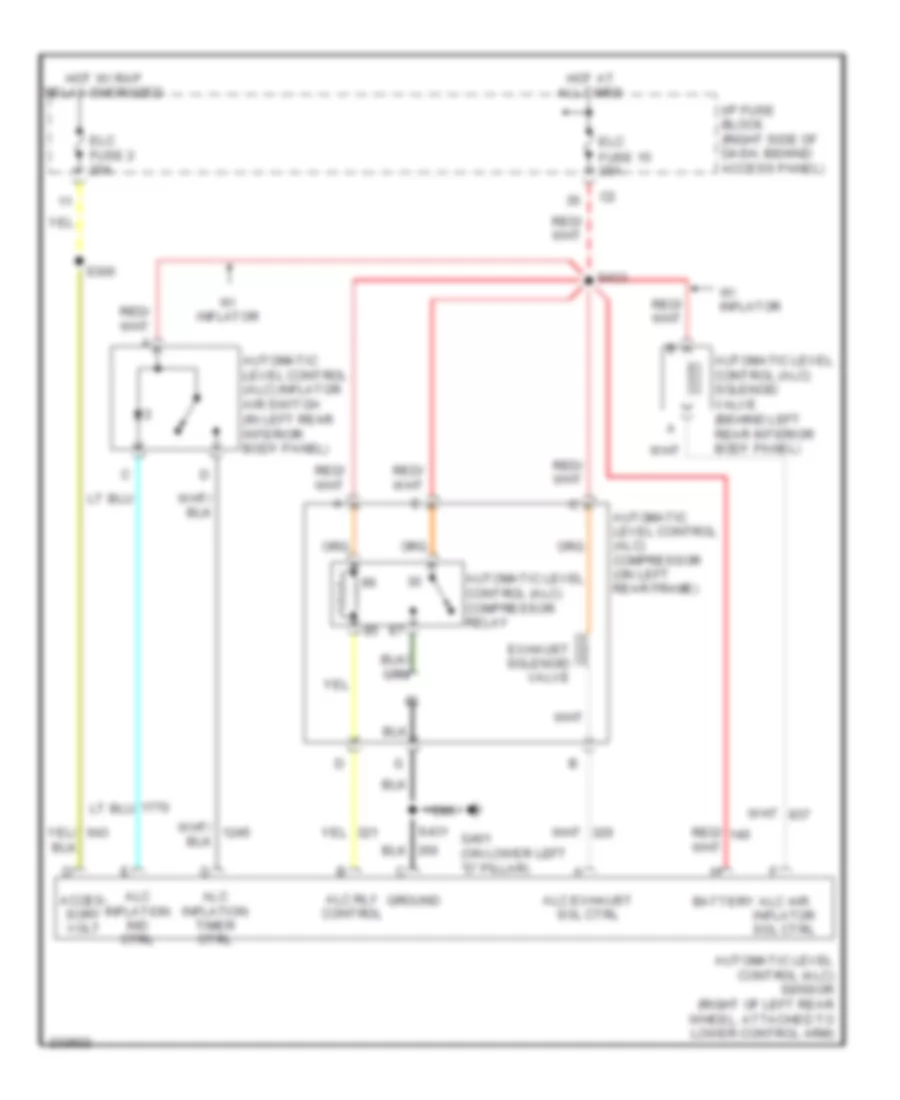
ELECTRONIC SUSPENSION Electronic Suspension Wiring Diagram for Chevrolet Uplander LS 2007 List of elements for Electronic Suspension Wiring Diagram for Chevrolet Uplander LS 2007: 24 Acces- sory volt Alc air inflator sol ctrl Alc exhaust sol ctrl Alc inflation ind ctrl Alc inflation timer ctrl Alc rly control Automatic level control (alc) compressor (on left rear frame) Automatic level control (alc) compressor relay Automatic level control (alc) inflator air switch (in left rear interior body panel) Automatic level control (alc) sensor (right of left rear wheel, attached to lower control arm) Automatic level control (alc) solenoid valve (behind left rear interior body panel) Battery Elc fuse 15 25a Elc fuse 2 20a Exhaust solenoid valve G401 (on lower left "d" pillar) Ground Hot at all times Hot w/ rap relay energized I/p fuse block (right side of dash, behind access panel) S300 S431 S433 W/ inflator
ENGINE PERFORMANCE
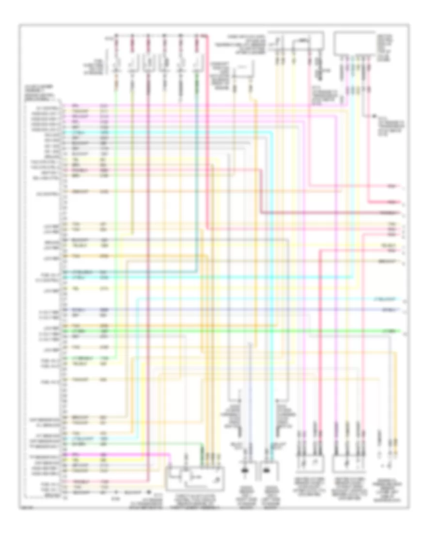
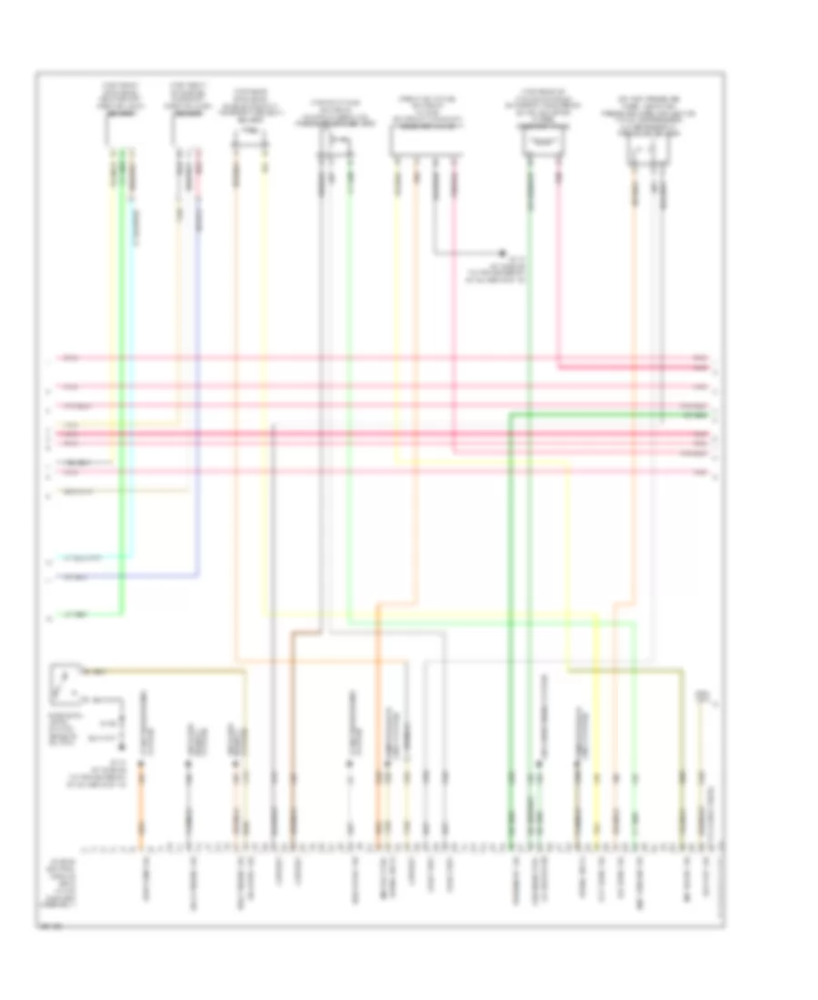
3.9L VIN 1 3.9L VIN 1, Engine Performance Wiring Diagram (1 of 4) for Chevrolet Uplander LS 2007 List of elements for 3.9L VIN 1, Engine Performance Wiring Diagram (1 of 4) for Chevrolet Uplander LS 2007: 59 (at engine to transmission stud above g115) (front of engine) (in air cleaner assembly) (left side of engine block) 5 volt ref Bare Camshaft position (cmp) actuator solenoid Ckp sensor sig Cmp sensor sig Engine control module (ecm) Engine oil pressure (eop) sensor (lower left side of engine block) Fuel inj 1 Fuel inj 2 Fuel inj 3 Fuel inj 4 Fuel inj 5 Fuel inj 6 Fuel injectors (on top of engine) G113 G113 (at engine to transmission stud above g115) Ground Heated oxygen sensor (ho2s) 1 (in right bank exhaust manifold, before catalytic converter) Heated oxygen sensor (ho2s) 2 (in exhaust, after catalytic converter) Ho2s heater 1 Ho2s heater 2 Ho2s sig high 1 Ho2s sig high 2 Ho2s sig low 1 Ho2s sig low 2 Iat Iat sens sig Ic 3 control Ic1 control Ic2 control Ignition 1 Ignition control module (icm) (top of valve cover) Knock sensor (ks) 1 (right side of engine block) Knock sensor (ks) 2 Ks 1 sig Ks 2 sig Low ref Maf Maf sens sig Mass air flow (maf)/ intake air temperature (iat) sensor (in air intake, after cleaner) Nca Oil sens sig Pnk S142 S151 (in eng harness, 15 cm from ecm c2) S153 (in eng harness, 10 cm from ecm c2) S155 Sol high ctrl Tac mtr ctrl 1 Tac mtr ctrl 2 Tan Tan c Throttle actuator control (tac) module (rear of engine, on throttle body assembly) Tp sensor sig 1 Tp sensor sig 2 3.9L VIN 1, Engine Performance Wiring Diagram (2 of 4) for Chevrolet Uplander LS 2007 List of elements for 3.9L VIN 1, Engine Performance Wiring Diagram (2 of 4) for Chevrolet Uplander LS 2007: 42 (67 to 73 not used) (at engine to transmission stud above g115) (front of intake manifold) intake manifold tuning (imt) solenoid valve (on high pressure hose, near high pressure hose connection to a/c compressor) a/c refrigerant pressure sensor (top front of engine) camshaft position (cmp) sensor (top front of engine) crankshaft position (ckp) sensor (top of intake manifold) manifold absolute pressure (map) sensor (top rear of engine) engine coolant temperature (ect) sensor (top rear of intake manifold) evaporative emission (evap) canister purge solenoid valve 5 volt ref A/c sens sig Air conditioning system Anti-lock Brakes anti-lock Computer data lines system Deli torque sig Ect sens sig Engine control module (ecm) (in air cleaner assembly) Engine oil level switch (base of oil pan) G113 G113 (at engine to transmission stud above g115) Gen cycle sig Gen turn sig Imc val ctrl Imt valve sig Lines system computer data Lo speed fan Low ref Map sensor sig Oil level sig Out put sig Park/neut sig Pnk Red Req torque sig S155 Serial data Solenoid ctrl System System brakes System starting/charging Tan 3.9L VIN 1, Engine Performance Wiring Diagram (3 of 4) for Chevrolet Uplander LS 2007 List of elements for 3.9L VIN 1, Engine Performance Wiring Diagram (3 of 4) for Chevrolet Uplander LS 2007: 27 Accelerator pedal position (app) sensor (on accelerator bracket) Acces volt Automatic transmission Early production Elec ign fuse 15a Eng snsr/ evap fuse 15a Etc fuse 18 15a Fuel inj fuse 15a Fuel pump fuse 2 15a Fuel pump relay G113 (at engine to transmission stud above g115) Hot at all times I/p fuse block (right c1 side of dash, behind access panel) Ign main relay Late production Pcm etc fuse 9 15a Pcm ign fuse 14 10a Pnk Pwr/ trn relay S155 S159 S175 Sig System transmissions Tan Transmission control module (tcm) (behind coolant reservoir) Underhood fuse block (in underhood compt, above right front wheel well) 3.9L VIN 1, Engine Performance Wiring Diagram (4 of 4) for Chevrolet Uplander LS 2007 List of elements for 3.9L VIN 1, Engine Performance Wiring Diagram (4 of 4) for Chevrolet Uplander LS 2007: 51 (on lower left "b" pillar) g301 5 volt ref A/c clutch relay Acc Accessory volt Air conditioning system App sensor 1 sig App sensor 2 sig Battery Body control module (bcm) (below left side of dash, left of steering column) Cnstr/ vent fuse 19 10a Computer data lines system Cruise control system Cruise ctrl sig Engine control module (ecm) (in air cleaner assembly) Evap vent sol Evaporative emission (evap) canister vent solenoid (long wheelbase: under vehicle, on top right side of fuel tank) (short wheelbase: under vehicle, above fuel tank) Frt wsw fuse 24 15a Fuel level sig Fuel pump & sender assembly (in top of fuel tank) Fuel pump relay Fuel tank pressure (ftp) sensor (top of fuel tank) Fuel tank sens Hi speed fan rly Hot at all times I/p fuse block (right side of dash, behind access panel) Ignition 1 voltage Ignition switch Instrument panel cluster (ipc) Lock Logic Low ref Malfunction indicator lamp (mil) Mil control Pnk Rly ctrl Run S139 S273 S279 S306 (w/ handicapped) (in body harness, 8 cm from c200) S371 (in fuel tank harness, 30 cm from c305) Serial data Start Starter rly ctrl Starting/charging system Stop lamp volt Tan Underhood fuse block (in underhood compt, (above right front wheel well) Underhood fuse block (in underhood compt, above right front wheel well) Vehicle speed sig
3.9L VIN W 3.9L VIN W, Engine Performance Wiring Diagram (1 of 4) for Chevrolet Uplander LS 2007 List of elements for 3.9L VIN W, Engine Performance Wiring Diagram (1 of 4) for Chevrolet Uplander LS 2007: 59 (at engine to transmission stud above g115) (front of engine) (in air cleaner assembly) (left side of engine block) 5 volt ref Bare Camshaft position (cmp) actuator solenoid Ckp sensor sig Cmp sensor sig Engine control module (ecm) Engine oil pressure (eop) sensor (lower left side of engine block) Fuel inj 1 Fuel inj 2 Fuel inj 3 Fuel inj 4 Fuel inj 5 Fuel inj 6 Fuel injectors (on top of engine) G113 G113 (at engine to transmission stud above g115) Ground Heated oxygen sensor (ho2s) 1 (in right bank exhaust manifold, before catalytic converter) Heated oxygen sensor (ho2s) 2 (in exhaust, after catalytic converter) Ho2s heater 1 Ho2s heater 2 Ho2s sig high 1 Ho2s sig high 2 Ho2s sig low 1 Ho2s sig low 2 Iat Iat sens sig Ic 3 control Ic1 control Ic2 control Ignition 1 Ignition control module (icm) (top of valve cover) Knock sensor (ks) 1 (right side of engine block) Knock sensor (ks) 2 Ks 1 sig Ks 2 sig Low ref Maf Maf sens sig Mass air flow (maf)/ intake air temperature (iat) sensor (in air intake, after cleaner) Nca Oil sens sig Pnk S142 S151 (in eng harness, 15 cm from ecm c2) S153 (in eng harness, 10 cm from ecm c2) S155 Sol high ctrl Tac mtr ctrl 1 Tac mtr ctrl 2 Tan Tan c Throttle actuator control (tac) module (rear of engine, on throttle body assembly) Tp sensor sig 1 Tp sensor sig 2 3.9L VIN W, Engine Performance Wiring Diagram (2 of 4) for Chevrolet Uplander LS 2007 List of elements for 3.9L VIN W, Engine Performance Wiring Diagram (2 of 4) for Chevrolet Uplander LS 2007: 42 (67 to 73 not used) (at engine to transmission stud above g115) (front of intake manifold) intake manifold tuning (imt) solenoid valve (on high pressure hose, near high pressure hose connection to a/c compressor) a/c refrigerant pressure sensor (top front of engine) camshaft position (cmp) sensor (top front of engine) crankshaft position (ckp) sensor (top of intake manifold) manifold absolute pressure (map) sensor (top rear of engine) engine coolant temperature (ect) sensor (top rear of intake manifold) evaporative emission (evap) canister purge solenoid valve 5 volt ref A/c sens sig Air conditioning system Anti-lock Brakes anti-lock Computer data lines system Deli torque sig Ect sens sig Engine control module (ecm) (in air cleaner assembly) Engine oil level switch (base of oil pan) G113 G113 (at engine to transmission stud above g115) Gen cycle sig Gen turn sig Imc val ctrl Imt valve sig Lines system computer data Lo speed fan Low ref Map sensor sig Oil level sig Out put sig Park/neut sig Pnk Red Req torque sig S155 Serial data Solenoid ctrl System System brakes System starting/charging Tan 3.9L VIN W, Engine Performance Wiring Diagram (3 of 4) for Chevrolet Uplander LS 2007 List of elements for 3.9L VIN W, Engine Performance Wiring Diagram (3 of 4) for Chevrolet Uplander LS 2007: 27 Accelerator pedal position (app) sensor (on accelerator bracket) Acces volt Automatic transmission Early production Elec ign fuse 15a Eng snsr/ evap fuse 15a Etc fuse 18 15a Fuel inj fuse 15a Fuel pump fuse 2 15a Fuel pump relay G113 (at engine to transmission stud above g115) Hot at all times I/p fuse block (right c1 side of dash, behind access panel) Ign main relay Late production Pcm etc fuse 9 15a Pcm ign fuse 14 10a Pnk Pwr/ trn relay S155 S159 S175 Sig System transmissions Tan Transmission control module (tcm) (behind coolant reservoir) Underhood fuse block (in underhood compt, above right front wheel well) 3.9L VIN W, Engine Performance Wiring Diagram (4 of 4) for Chevrolet Uplander LS 2007 List of elements for 3.9L VIN W, Engine Performance Wiring Diagram (4 of 4) for Chevrolet Uplander LS 2007: 51 (on lower left "b" pillar) g301 5 volt ref A/c clutch relay Acc Accessory volt Air conditioning system App sensor 1 sig App sensor 2 sig Battery Body control module (bcm) (below left side of dash, left of steering column) Cnstr/ vent fuse 19 10a Computer data lines system Cruise control system Cruise ctrl sig Engine control module (ecm) (in air cleaner assembly) Evap vent sol Evaporative emission (evap) canister vent solenoid (long wheelbase: under vehicle, on top right side of fuel tank) (short wheelbase: under vehicle, above fuel tank) Frt wsw fuse 24 15a Fuel level sig Fuel pump & sender assembly (in top of fuel tank) Fuel pump relay Fuel tank pressure (ftp) sensor (top of fuel tank) Fuel tank sens Hi speed fan rly Hot at all times I/p fuse block (right side of dash, behind access panel) Ignition 1 voltage Ignition switch Instrument panel cluster (ipc) Lock Logic Low ref Malfunction indicator lamp (mil) Mil control Pnk Rly ctrl Run S139 S273 S279 S306 (w/ handicapped) (in body harness, 8 cm from c200) S371 (in fuel tank harness, 30 cm from c305) Serial data Start Starter rly ctrl Starting/charging system Stop lamp volt Tan Underhood fuse block (in underhood compt, (above right front wheel well) Underhood fuse block (in underhood compt, above right front wheel well) Vehicle speed sig
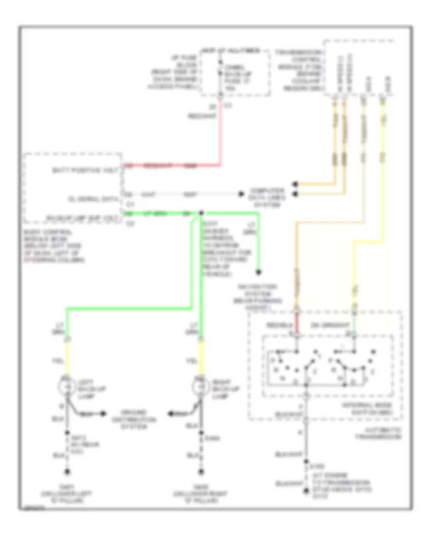
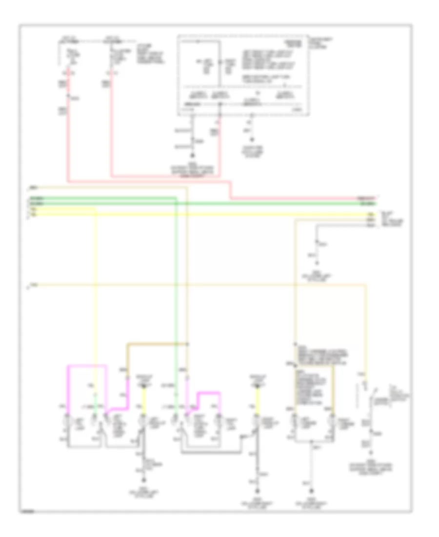
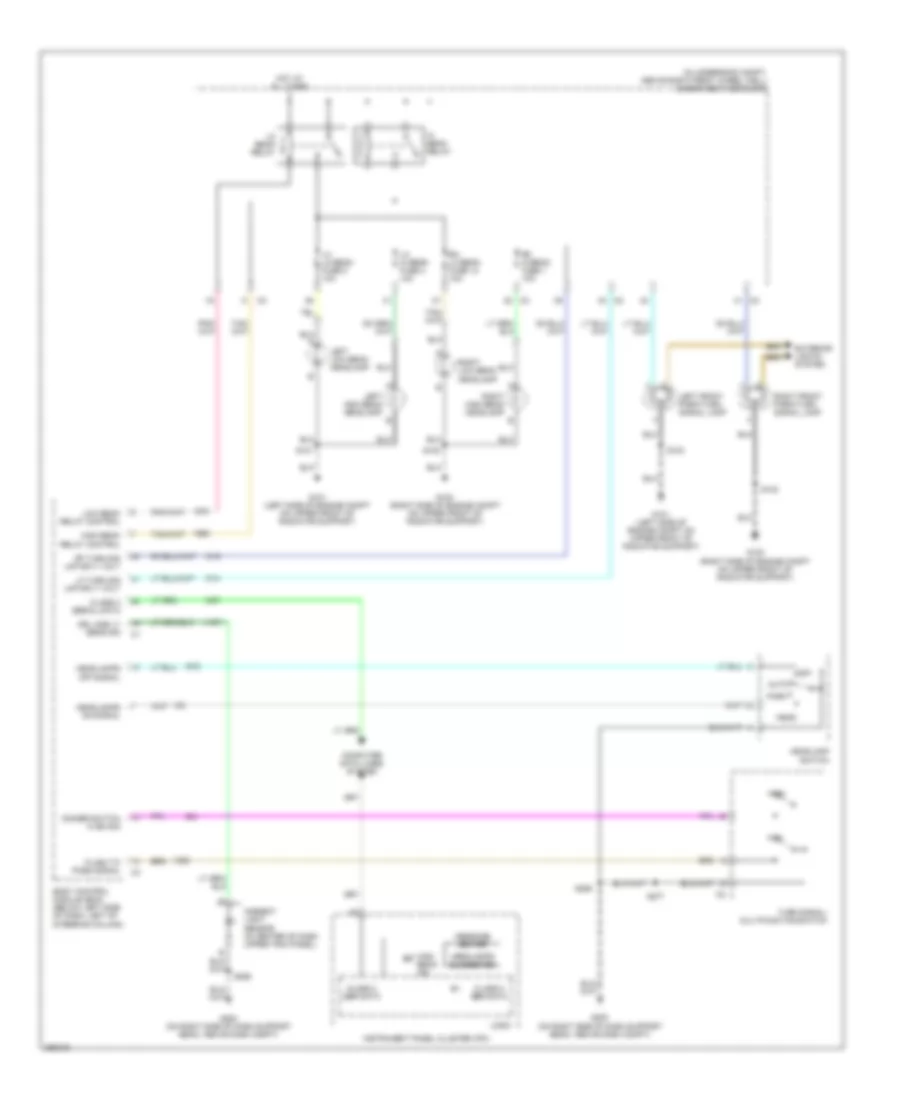
EXTERIOR LIGHTS Backup Lamps Wiring Diagram for Chevrolet Uplander LS 2007 List of elements for Backup Lamps Wiring Diagram for Chevrolet Uplander LS 2007: 26 (at engine to transmission stud above g115) g113 Automatic transmission Backup lmp sup volt Batt positive volt Body control module (bcm) (below left side of dash, left of steering column) Chmsl back-up fuse 17 15a Cl serial data Computer data lines system G400 (on lower right "d" pillar) G401 (on lower left "d" pillar) Ground distribution system Hi speed (+) Hi speed (-) Hot at all times I/p fuse block (right side of dash, behind access panel) Internal mode switch (ims) Left back-up lamp Navigation system (rear parking assist) Right back-up lamp S155 S317 (in body harness, 10 cm from breakout for c313 toward rear of vehicle) S404 Sig a Sig b Tan Transmission control module (tcm) (behind coolant reservoir) Exterior Lamps Wiring Diagram (1 of 2) for Chevrolet Uplander LS 2007 List of elements for Exterior Lamps Wiring Diagram (1 of 2) for Chevrolet Uplander LS 2007: 51 (in liftgate harness, 26.5 cm from chmsl) s913 (on lower right "b" pillar) 10v ref Auto Batt pos voltage Batt positive voltage Body control module (bcm) (below left side of dash, left of steering column) Brake pedal position sensor (above brake pedal assembly) Brk pos sens sig Center high mounted stop lamp Chmsl resistor Class 2 ser data Computer data lines system G100 (right side of engine compt on upper front of radiator support) G101 (left side of engine compt on upper front of radiator support) G200 (on right side of dash support beam, above dash compt) G302 Hazard sw sig Head Headlight switch Hot at all times I/p fuse block (right side of dash, behind access panel) Left front marker lamp Left front park/ turn signal lamp Lf trn sig vlt Low ref Lr stop/turn lmp vlt Lt trn sig sw Nca Off Park Park lamp relay 28 Park/lamp fuse 20 10a Prk lmp rly ctrl Prk lmp sw on sig Rf trn sig vlt Right front marker lamp Right front park/ turn signal lamp Rr stop/turn lmp vlt Rt trn sig sw S100 S101 S102 S103 S255 S277 S913 Stop/ trn fuse 12 20a Tan Turn signal/ multi-function switch (on left side of upper steering column) Underhood fuse block (in underhood compt, above right front wheel well) Exterior Lamps Wiring Diagram (2 of 2) for Chevrolet Uplander LS 2007 List of elements for Exterior Lamps Wiring Diagram (2 of 2) for Chevrolet Uplander LS 2007: 35 Back-up lamp circuit Class 2 ser data Cluster/ hvac fuse 8 10a Computer data lines system Elc fuse 25a G200 (on right side of dash support beam, above dash compt) G400 (on lower right "d" pillar) G401 (on lower left "d" pillar) Ground Hazard switch Hot at all times I/p fuse block (right side of dash, behind access panel) I/p multi- function switch Instrument panel cluster Left back-up lamp Left front turn lamp out left rear turn lamp out park lamps on right front turn lamp out right rear turn lamp out Left license lamp Left tail lamp Left tail/ stop & turn signal lamp Left turn sig ind Logic Message center Right back-up lamp Right license lamp Right tail lamp Right tail/ stop & turn signal lamp Right turn sig ind S255 S404 S431 S433 S900 (in liftgate harness, 6.5 cm from breakout for right license lamp toward rear window wiper motor) S911 Service park lamp turn turn signal on Tan
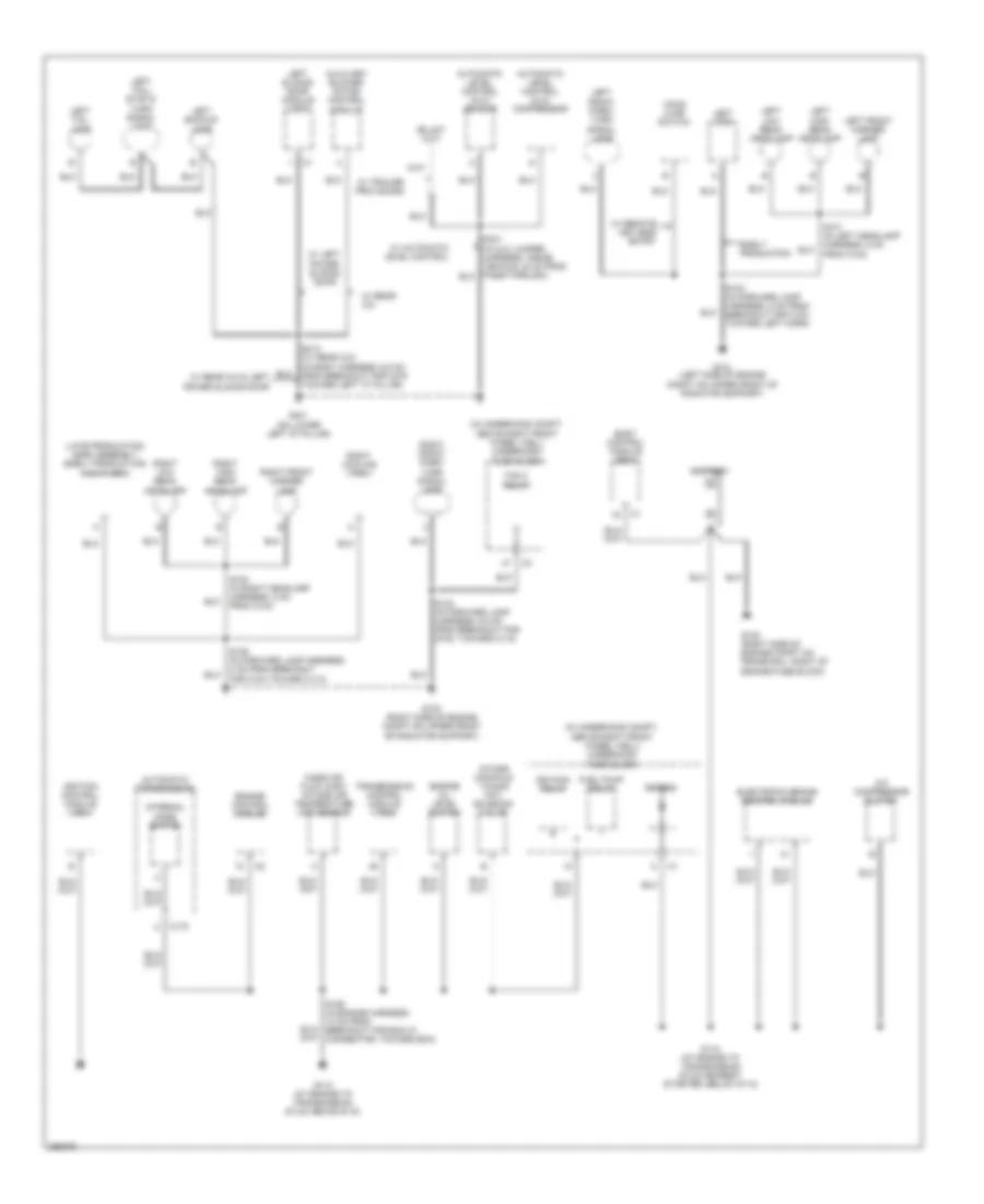
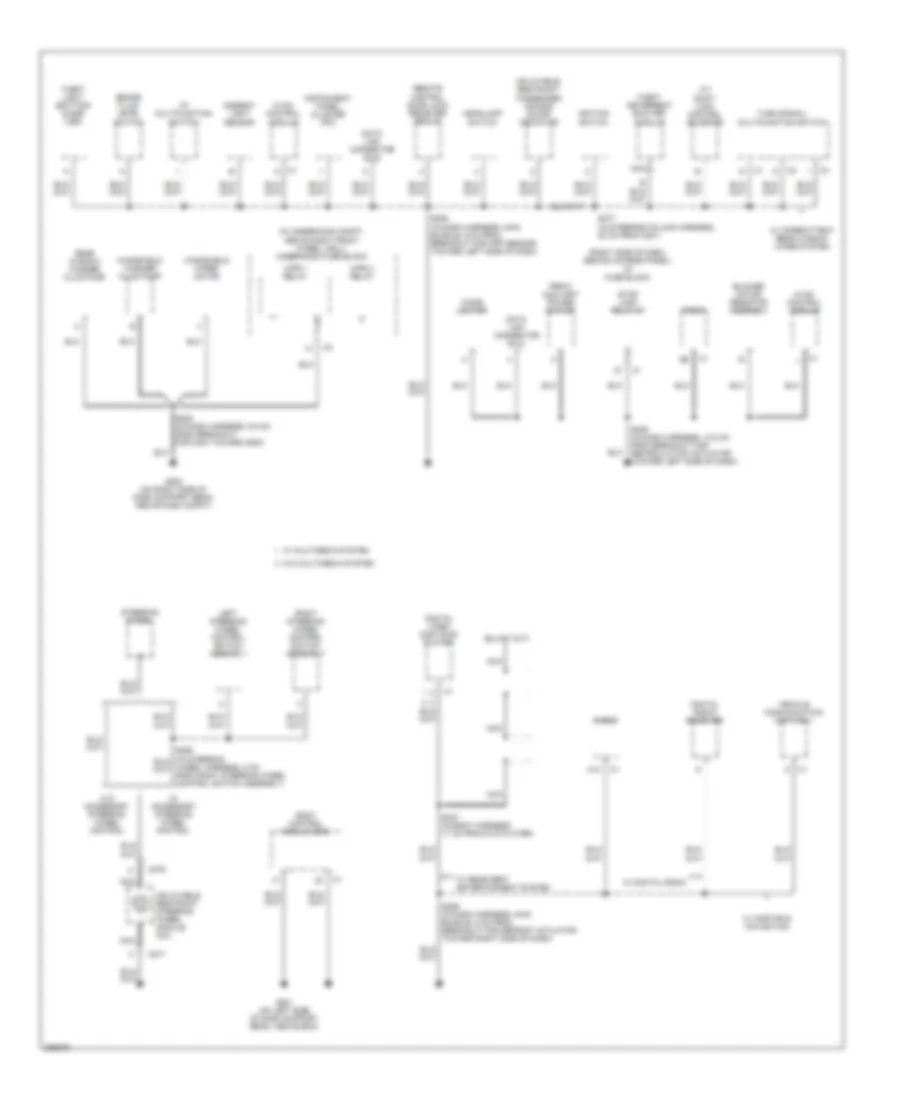
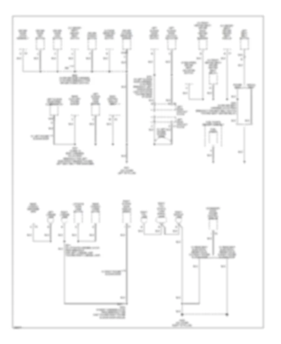
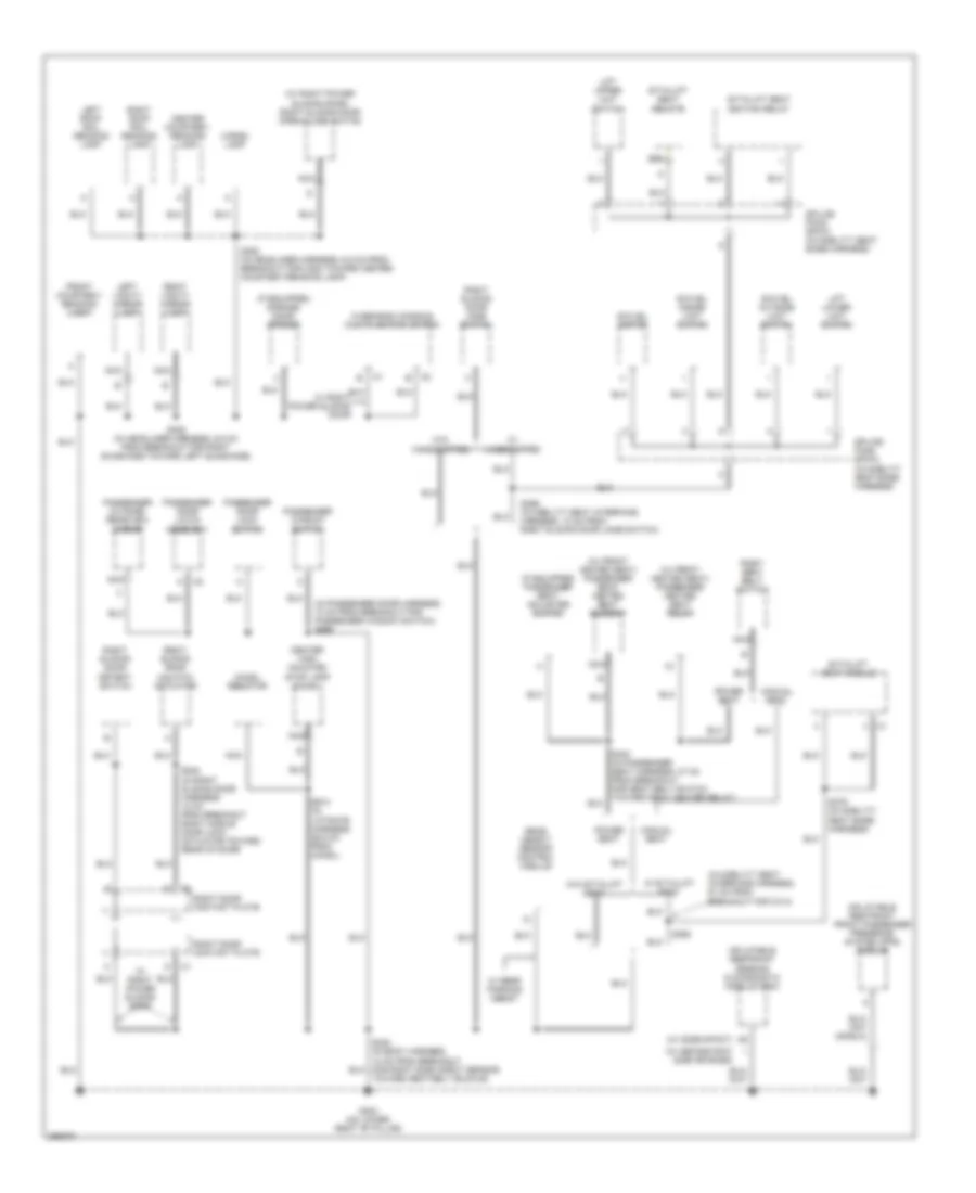
GROUND DISTRIBUTION Ground Distribution Wiring Diagram (1 of 4) for Chevrolet Uplander LS 2007 List of elements for Ground Distribution Wiring Diagram (1 of 4) for Chevrolet Uplander LS 2007: 58 (in underhood compt, above right front wheel well) underhood fuse block (late production) horn assembly (early production) right horn A/c compressor clutch Automatic level control (alc) compressor Automatic level control (alc) sensor Automatic transmission Auxiliary blower motor control module Battery Body control module (bcm) C175 Diode 3 Early production Electronic brake control module Engine control module Engine oil level switch Fan 2 relay Fuel pump relay G100 (right side of engine compt on upper front of radiator support) G101 (left side of engine compt on upper front of radiator support) G102 (right side of engine compt on frame rail, right of engine fuse block) G113 (at engine to transmission stud above g115) G115 (at engine to transmission stud nearest starter, below g113) G401 (on lower left "d" pillar) Hood ajar switch Ign main relay Ignition control module (icm) Intake manifold tuning (imt) solenoid valve Internal mode switch Left backup lamp Left front marker lamp Left front park/ turn signal lamp Left high beam headlamp Left horn Left low beam headlamp Left sliding door module (lsdm) Left tail lamp Left tail/ stop & turn signal lamp Mass air flow (maf)/ intake air temperature (iat) sensor Right cooling fan Right front marker lamp Right front park/ turn signal lamp Right high beam headlamp Right low beam headlamp S100 (in right headlamp harness, 8 cm from c104) S101 (in left headlamp harness, 8 cm from c103) S102 (in forward lamp harness, 6.5 cm from breakout for g100, toward c110) S103 (in forward lamp harness, 5 cm from breakout for c103, toward left horn) S106 (in forward lamp harness, 8 cm from breakout for c104 toward c110) S155 (in engine harness, 10 cm from breakout for ecm c1 connector, toward ecm) S413 (w/ rear a/c) (in body harness, 6.5 cm from breakout for c479 toward left "c" pillar) S431 (in alc jumper harness, inside vehicle, 24 cm from pass-through) Transmission control module (tcm) W/ automatic level control W/ left power sliding door W/ rear a/c W/ rear a/c & left power sliding door W/ remote keyless entry W/ trailer provisions Ground Distribution Wiring Diagram (2 of 4) for Chevrolet Uplander LS 2007 List of elements for Ground Distribution Wiring Diagram (2 of 4) for Chevrolet Uplander LS 2007: 54 (in underhood compt, above right front wheel well) underhood fuse block (right side of dash, behind access panel) i/p fuse block A/t shift lock control solenoid A12 Ambient light sensor Blower motor resistor assembly Body control module (bcm) Brake fluid level switch C277 C279 Cigar lighter Data link connector (dlc) Digital radio receiver Digital video disc (dvd) player Front auxiliary power outlet G200 (on right side of dash support beam, above dash compt) G201 (on left side of dash support beam, above bcm) Headlamp switch Hvac control module I/p multifunction switch Ignition switch Inflatable restraint passenger air bag on/off indicator Inflatable restraint steering wheel module coil Instrument panel cluster (ipc) Left steering wheel control switch assembly Nca Radio Rear window washer fluid pump Remote control door lock receiver (rcdlr) Right steering wheel control switch assembly S200 (in dash harness, 6.5 cm from breakout for c204 toward g200) S246 (in dash harness, 12.5 cm from breakout for recirculation actuator toward left side of dash) S255 (in dash harness, main bundle, 9 cm from breakout for app sensor toward left side of dash) S259 (in dash harness, main bundle, 5 cm from breakout for defrost actuator toward right side of dash) S277 (in steering column harness, 20 cm from c201) S337 (in body harness, 17 cm from dvd player) Steering wheel Stop lamp relay 27 Theft deterrent exciter module Theft light emitting diode (led) Turn signal/ multifunction switch Vehicle communication unit (vcu) W/ accessory steering wheel control W/ digital radio W/ intermittent rear window wiper system W/ multimedia system W/ onstar & navigation W/ rear seat entertainment system W/o accessory steering wheel control W/o multimedia system Windshield washer fluid pump Windshield wiper motor Wpr 1 relay Wpr 2 relay Ground Distribution Wiring Diagram (3 of 4) for Chevrolet Uplander LS 2007 List of elements for Ground Distribution Wiring Diagram (3 of 4) for Chevrolet Uplander LS 2007: 47 (if equipped) driver seat adjuster switch (w/ front heated seat) driver back heated seat element (w/ front heated seat) driver heated seat relay (w/ memory seat) driver memory seat module (w/ memory seat) memory seat switch Accessory ac/dc power control module Ag0 Body control module (bcm) Driver door key switch Driver door latch assembly Driver door lock switch Driver outside rearview mirror Driver window switch Fuel pump Fuel pump & sender assembly G301 (on lower left "b" pillar) G400 (on lower right "d" pillar) Left door contact plate Left license lamp Left seat belt switch Left sliding door detent switch Left sliding door jamb switch Left sliding door open/ close switch Left sliding door unlatch actuator Liftgate door jamb switch Manual seat Nca Outside rearview mirror switch Power seat Rear auxiliary power outlet Rear window defogger grid Rear window wiper motor Right backup lamp Right license lamp Right sliding door module (rsdm) Right tail lamp Right tail/ stop & turn signal lamp S331 (w/e59: in body harness, 6.5 cm from breakout for left side impact sensor toward left seat belt pretensioner) S351 (in driver seat harness, 6.5 cm from breakout for seat belt switch toward seat heater relay) S404 (in body harness, 6.5 cm from breakout for c480 toward right power sliding door module) S555 (in driver door harness, 10 cm from breakout for driver window switch) S751 (in left sliding door harness, 12 cm from breakout left middle door lock actuator toward rear of door) S911 (in liftgate harness, 6.5 cm from breakout for left license lamp toward right license lamp) W/ left power sliding door W/ rear seat electrical receptacle & right power sliding door W/ rear seat electrical receptacle, w/o right power sliding door W/ right power sliding door Ground Distribution Wiring Diagram (4 of 4) for Chevrolet Uplander LS 2007 List of elements for Ground Distribution Wiring Diagram (4 of 4) for Chevrolet Uplander LS 2007: 60 (if equipped) garage door opener (if equipped) passenger seat adjuster switch (in mobility seat interface harness, 57 cm from breakout for c314) (in passenger door harness, 10 cm from breakout for passenger window switch) s666 (w/ front heated seat) passenger back heated seat element (w/ front heated seat) passenger heated seat relay (w/ right power sliding door) right sliding door open/close switch (w/ second row side air bags) (w/ side impact) Cargo lamp Center courtesy/ reading lamp Center high mounted stop lamp (chmsl) Chmsl resistor Front courtesy/ reading lamp G302 (on lower right "b" pillar) Inflatable restraint front passenger presence system (pps) module Inflatable restraint sensing & diagnostic module (sdm) Left roof rail reading lamp Left vanity mirror lamp Lift lower limit switch Lift upper limit switch Manual seat Nca Overhead console multifunction switch Passenger door latch assembly Passenger door lock switch Passenger outside rearview mirror Passenger window switch Power seat Rear object sensor control module Right door contact plate Right roof rail reading lamp Right seat belt switch Right sliding door detent switch Right sliding door jamb switch Right sliding door unlatch actuator Right vanity mirror lamp S340 (in passenger seat harness, 27 cm from breakout for seat belt switch toward seat heater relay) S360 S366 (in mobility seat interface harness, 10 cm from right sliding door jamb switch) S379 (in mobility seat base harness) S380 (in headliner harness, 6.5 cm from breakout for c308 toward center courtesy/reading lamp) S388 (in headliner harness, 6.5 cm from breakout for right sunshade toward left sunshade) S848 (in right sliding door harness, 12 cm from breakout right middle door lock actuator toward rear of door) S913 (in liftgate harness, 26.5 cm from chmsl) Sit-n-lift seat ignition relay Sit-n-lift seat module Sit-n-lift seat remote Splice pack sp370 (in mobility seat base harness) Splice pack sp372 (in mobility seat base harness) Swivel inside limit switch Swivel motor Swivel outside limit switch Toward seat belt buckle) W/ handicapped W/ rear parking assist W/ right power sliding door W/ sit-n-lift seat W/o handicapped W/o sit-n-lift seat
HEADLIGHTS Headlights Wiring Diagram for Chevrolet Uplander LS 2007 List of elements for Headlights Wiring Diagram for Chevrolet Uplander LS 2007: 51 (in underhood compt, above right front wheel well) underhood fuse block Ambient light sensor (in center of dash upper trim panel) Auto Body control module (bcm) (below left side of dash, left of steering column) Class 2 ser data Class 2 serial data Computer data lines system Dimmer switch hi bm sig Drl amb lt sens sig Exterior lights system Flash to pass signal Ftp G100 (right side of engine compt on upper front of radiator support) G101 (left side of engine compt on upper front of radiator support) G200 (on right side of dash support beam, above dash compt) Head Headlamp switch Headlamps off signal Headlamps on signal Headlamps suggested Hi beam relay High High beam ind High beam relay control Hot at all times Instrument panel cluster (ipc) Left front park/turn signal lamp Left high beam headlamp Left low beam headlamp Lf turn sig lmp sply volt Lh hi beam fuse 4 10a Lh lo beam fuse 8 10a Lo beam relay Logic Low beam relay control Message center Off Park Rf turn sig lmp sply volt Rh hi beam fuse 1 10a Rh lo beam fuse 12 10a Right front park/turn signal lamp Right high beam headlamp Right low beam headlamp S100 S101 S102 S103 S255 S277 Turn signal/ multifunction switch
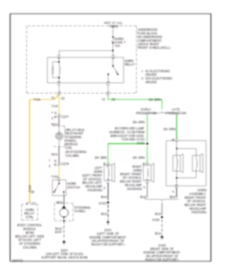
HORN Horn Wiring Diagram for Chevrolet Uplander LS 2007 List of elements for Horn Wiring Diagram for Chevrolet Uplander LS 2007: 29 (in forward lamp harness, 13 cm from breakout for g100, toward c110) s104 (in steering column) Body control module (bcm) (below left side of dash, left of steering column) C277 C279 Cruise w/o electronic cruise Early production G100 (right side of engine compartment on upper front of radiator support) G101 (left side of engine compartment on upper front of radiator support) G201 (on left side of dash support beam, above bcm) H b Horn assembly (right front of vehicle, below right headlamp housing) Horn fuse 7 15a Horn relay Horn relay ctrl Horn switch Hot at all times Housing) Inflatable restraint steering wheel module coil Late production Left horn (left front of vehicle, below left headlamp a Nca Right horn (right front of vechile, below right headlamp a housing) S103 S106 Steering wheel Tan Underhood fuse block (in underhood compartment, above right front wheelwell) W/ electronic
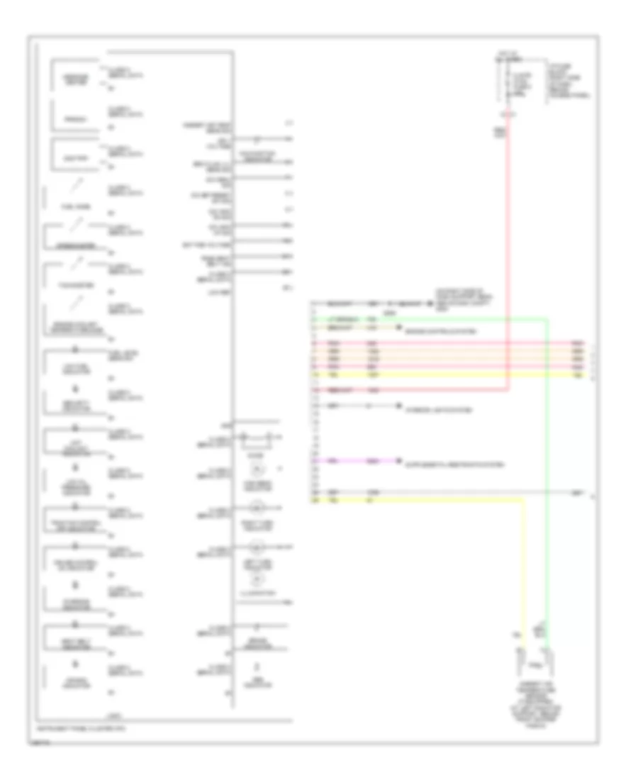
INSTRUMENT CLUSTER Instrument Cluster Wiring Diagram (1 of 2) for Chevrolet Uplander LS 2007 List of elements for Instrument Cluster Wiring Diagram (1 of 2) for Chevrolet Uplander LS 2007: 48 (on right side of dash support beam, above dash compt) g200 Abs indicator Air bag indicator Ambient air temp sens sig Ambient air temperature sensor (if equipped) (at left radiator support, behind front bumper fascia) Bat pos voltage Brake indicator Brk fluid lvl sens sig Charging indicator Chime Class 2 serial data Clstr/ hvac fuse 8 10a Cruise control on indicator Dic info dn sig Dic info up sig Dic menu sig Dic set/reset sw sig Engine controls system Engine coolant temperature gage Fuel gage Fuel level sens sig Gnd High beam indicator Hot at all times Hot coolant indicator I/p fuse block (right side of dash, behind access panel) Ign 1 voltage Illumination Instrument panel cluster (ipc) Interior lights system Left turn indicator Logic Low fuel indicator Low oil pressure indicator Low ref Malfunction indicator Message center Odo/trip Pass seat belt ind Pnk Prnd321 Right turn indicator S255 Seat belt indicator Security indicator Speedometer Tachometer Traction control off indicator Instrument Cluster Wiring Diagram (2 of 2) for Chevrolet Uplander LS 2007 List of elements for Instrument Cluster Wiring Diagram (2 of 2) for Chevrolet Uplander LS 2007: 29 (in fuel tank harness, 30 cm from c305) s371 5v ref 1 Body control module (bcm) (below left side of dash, left of steering column) Brake fluid level switch (at left rear of engine compt, in master cylinder fluid reservoir) Class 2 serial data Computer data lines system Engine control module (ecm) (in air cleaner assembly) Engine controls system Engine oil level switch (base of oil pan) Engine oil pressure (eop) sensor (lower left side of engine block) Fuel level sensor Fuel lvl sens sig Fuel pump & sender assembly (in top of fuel tank) G113 (at engine to transmission stud above g115) G200 (on right side of dash support beam, above dash compt) I/p multifunction switch Info dn Info up Low ref Menu Oil lvl sw sig Oil pres sens sig Park brake sw sig Park brake switch (on park brake assembly) Pnk Reset or english/ metric S155 S255 Tan
INTERIOR LIGHTS Courtesy Lamps Wiring Diagram for Chevrolet Uplander LS 2007 List of elements for Courtesy Lamps Wiring Diagram for Chevrolet Uplander LS 2007: 53 (in headliner harness, 6.5 cm from breakout for c308 toward right sunshade) s382 A c2 Battery positive Body control module (bcm) (below left side of dash, left of steering column) C2 d Cargo lamp Center courtesy/ reading lamp Courtesy high ctrl Ctsy Ctsy defeat Ctsy lamps sw off Ctsy lamps sw on Ctsy on D c2 Driver door latch assembly (in rear driver door) Front courtesy/ reading lamp G200 (on right side of dash support beam, above dash compartment) G301 (on lower left "b" pillar) G302 (on lower right "b" pillar) G400 (on lower right "d" pillar) Headlamp switch Hot at all times I/p fuse block (right side of dash, behind access panel) Inadvertent power Int/ lamp fuse 5 10a Left roof rail reading lamp Left sliding door jamb switch (on lower left "c" pillar) Left vanity mirror lamp (if equipped) Lf door open sw Liftgate door jamb switch (in bottom middle of liftgate) Liftgate open sw Lr door open sw Nca Passenger door latch assembly (rear front passenger door) Rf door open sw Right roof rail reading lamp Right sliding door jamb switch (on lower right "c" pillar) Right vanity mirror lamp (if equipped) Rr door open sw S255 S331 S366 (w/ handicapped) S368 S380 S388 S555 S666 S911 Seats system Sit-n- lift seat diode 3 Tan W/ handicapped W/o handicapped Instrument Illumination Wiring Diagram for Chevrolet Uplander LS 2007 List of elements for Instrument Illumination Wiring Diagram for Chevrolet Uplander LS 2007: 74 (in steering wheel harness, 10 cm from left steering wheel control switch assembly) s295 A c1 A c2 Auto B c1 B c2 B4 c1 B5 c1 Battery b+ Body control module (bcm) (below left side of dash, left of steering column) Bright C1 j C1 k C277 c C279 c Dim Dimmer Dimming voltage ref Driver door lock switch Driver window switch Driver window switch) s551 G200 (on right side of dash support beam, above dash compartment) G201 (on left side of dash support beam, above bcm) G301 (on lower left "b" pillar) G302 (on lower right "b" pillar) Garage door opener (if equipped) Gnd Head Headlamp switch Hot at all times Hvac control module (in dash center trim panel, beneath radio) I/p dimming ctrl I/p fuse block (right side of dash, behind access panel) I/p multi- function switch Illum Inflatable restraint steering wheel module coil (in steering column) Instrument panel cluster (ipc) Int/ lamp fuse 5 10a Left sliding door open/ close switch (if equipped) (on left "b" pillar) Left steering wheel control switch assembly Logic Low ref Memory seat switch Nca Off Outside rearview mirror switch Overhead console multi- function switch Park Park lamps on Passenger door lock switch Passenger window switch Pnk Radio Right sliding door open/ close switch (on right "b" pillar) Right steering wheel control switch assembly S246 S251 S255 S257 (8.5 cm from breakout for ipc toward right side of dash) S293 S315 (18.5 cm from breakout for c313 toward rear of vehicle) S331 S380 S384 (in headliner harness, 13 cm from breakout for c308 toward right sunshade) S388 S555 S660 S666 Starting/ charging system Str/whl/ illum fuse 10 2a W/ accessory steering wheel control W/ driver 2 position memory W/ sliding door W/o sliding door
MEMORY SYSTEMS Driver"s Memory Seat Wiring Diagram for Chevrolet Uplander LS 2007 List of elements for Driver"s Memory Seat Wiring Diagram for Chevrolet Uplander LS 2007: 65 (4.5 cm from breakout for seat adjuster toward memory seat module) s353 25a 5v ref A10 A11 A12 B10 B11 B12 Back Batt (high current) Class 2 serial data Computer data lines system Driver Driver memory seat module (under driver seat) Driver seat adjuster motor assembly (under driver seat) Driver seat adjuster switch Driver seat recline motor (in driver seat back) Exit Front down Front up Front vert down Front vert down ctrl Front vert up Front vert up ctrl Front vertical motor Frt vert pos sens Fwd G301 (on lower left "b" pillar) Ground H (not used) Horizontal motor Horizontal pos sens Horz fwd Horz fwd ctrl Horz rwd Horz rwd ctrl Hot at all times I/p fuse block (right side dash, behind access panel) Interior lights system Low ref Memory 1 Memory 2 Memory seat switch Nca Pwr seats circuit breaker 31 Rear down Rear up Rear vert down Rear vert down ctrl Rear vert pos sens Rear vert up Rear vert up ctrl Rear vertical motor Recline back Recline fwd Recline fwd ctrl Recline pos sens Recline rwd Recline rwd ctrl S351 S357 (20.5 cm from breakout for seat adjuster toward memory seat module) S555 Tan Voltage ref
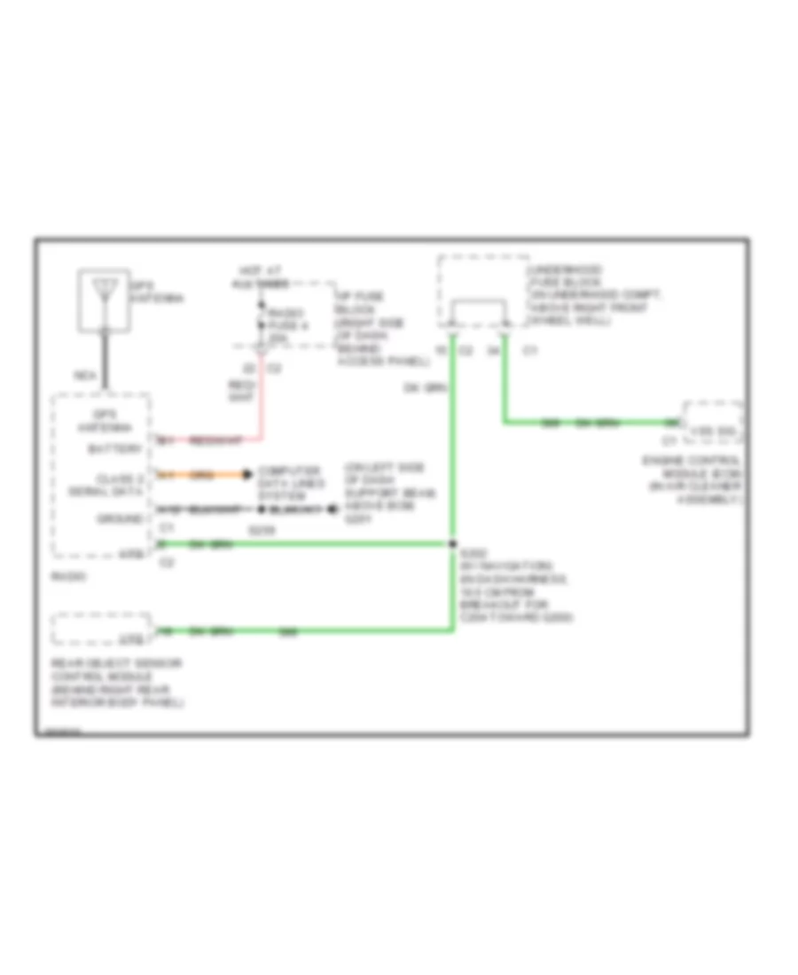
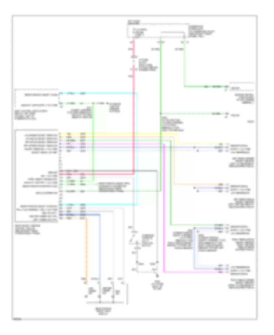
NAVIGATION Navigation Wiring Diagram for Chevrolet Uplander LS 2007 List of elements for Navigation Wiring Diagram for Chevrolet Uplander LS 2007: 19 (on left side of dash support beam, above bcm) g201 A12 Battery Class 2 serial data Computer data lines system Engine control module (ecm) (in air cleaner assembly) Gps antenna Ground Hot at all times I/p fuse block (right side of dash, behind access panel) Nca Radio Radio fuse 4 20a Rear object sensor control module (behind right rear interior body panel) S202 (w/ navigation) (in dash harness, 10.5 cm from breakout for c204 toward g200) S259 Underhood fuse block (in underhood compt, above right front wheel well) Vss Vss sig Parking Assistant Wiring Diagram for Chevrolet Uplander LS 2007 List of elements for Parking Assistant Wiring Diagram for Chevrolet Uplander LS 2007: 51 Backup lamp sply voltage Body control module (bcm) (below left side of dash, left of steering column) C2 b Center amber ind Center amber ind ctrl Engine control module (ecm) (in air cleaner assembly) Exterior lights & mirrors systems F c2 G302 (on lower Ground Hot in run or start Hvac/rpa/ cruise fuse 17 10a I/p fuse block (right side of dash, behind access panel) Ign 1 voltage Left amber ind Left amber ind ctrl Left rear corner object sensor (left outer edge of rear bumper fascia) Left rear middle object sensor (left center area of rear bumper fascia) Low reference Lr corner object sens sig Lr middle object sens sig Object sens low ref Object sens sply voltage Overhead console multi- function switch Park assist disable sw Pnk Radio Rear object sensor control module (behind right rear interior body panel) Rear parking assist (rpa) diagnostic connector (behind right rear interior body panel) Rear parking assist (rpa) display Rear parking assist chime Rear parking assist chime sig Rear parking diagnostic sig Red ind Red ind crtl Right "b" pillar) Right rear corner object sensor (right outer edge of rear bumper fascia) Right rear middle object sensor (right center area of rear bumper fascia) Rr corner object sens sig Rr middle object sens sig S202 (w/ navigation) (in dash harness, 10.5 cm from breakout for c204 toward g200) S317 (in body harness, 10 cm from breakout for c313 toward rear of vehicle) S320 S388 S480 (in rear parking assist harness, 18 cm from breakout for right middle object sensor toward left middle sensor) S482 (in rear parking assist harness, 24 cm from breakout for right middle object sensor toward left middle sensor) Sensor signal Telltale assembly sply voltage Underhood fuse block (in underhood compt, above right front wheel well) Vehicle speed sig Vss sig
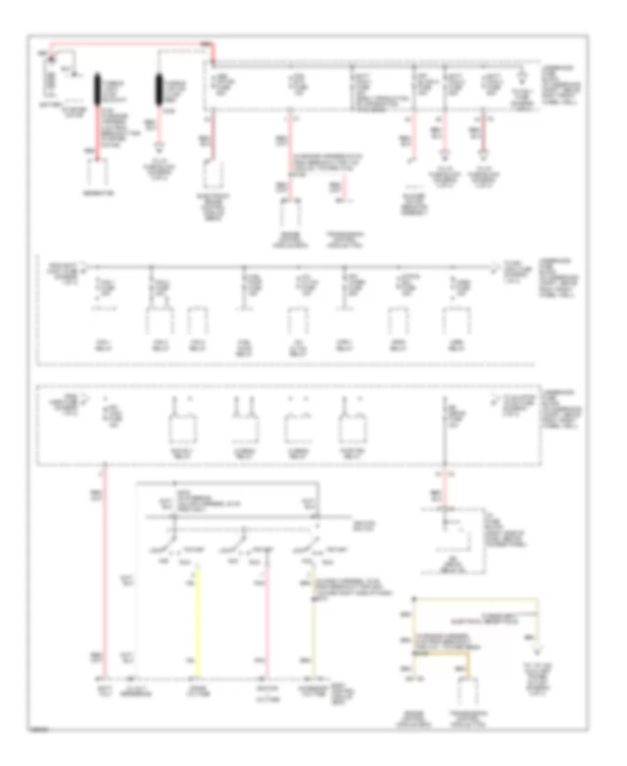
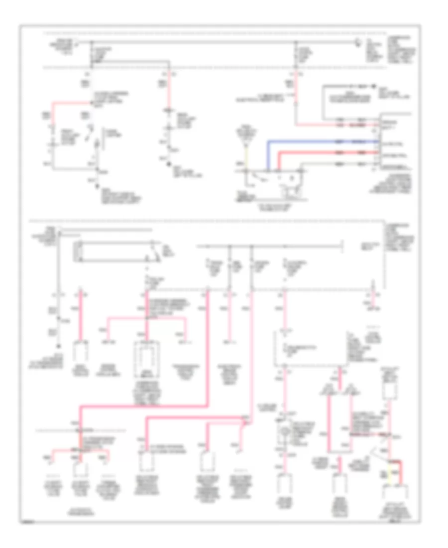
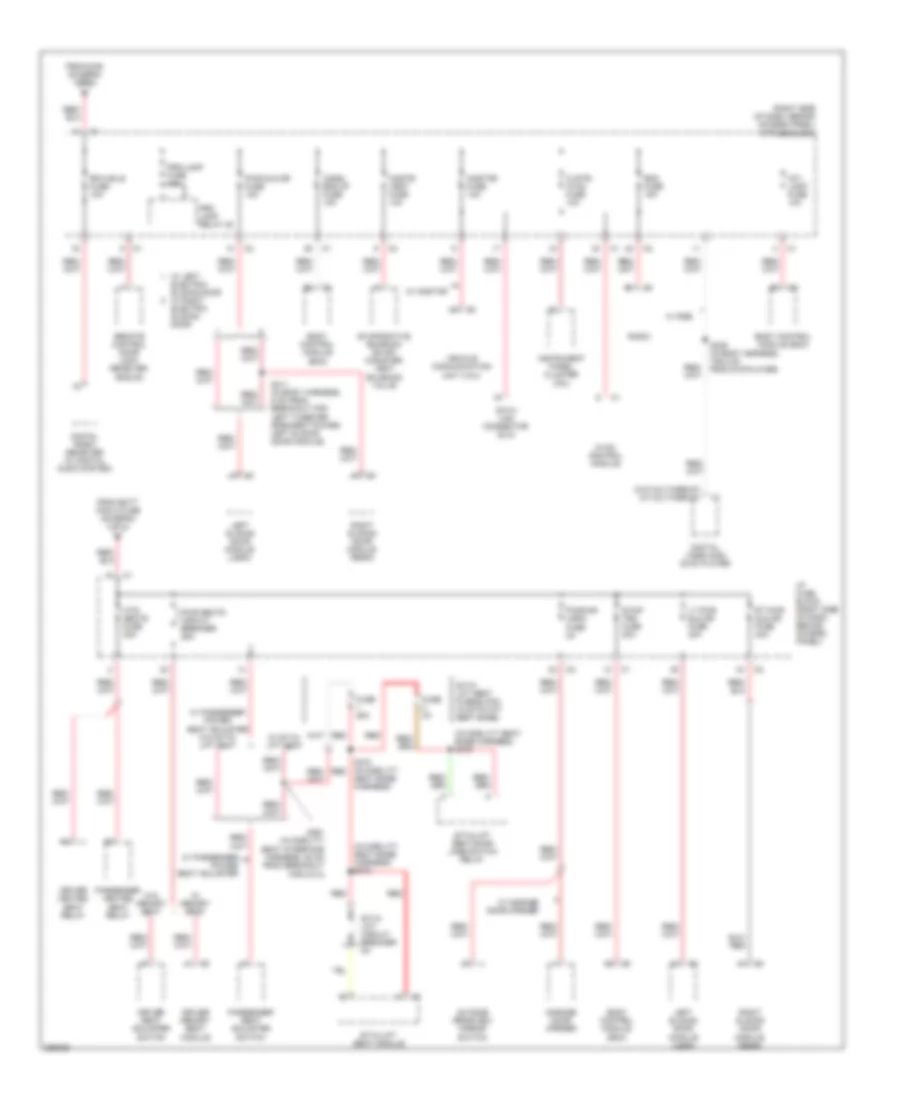
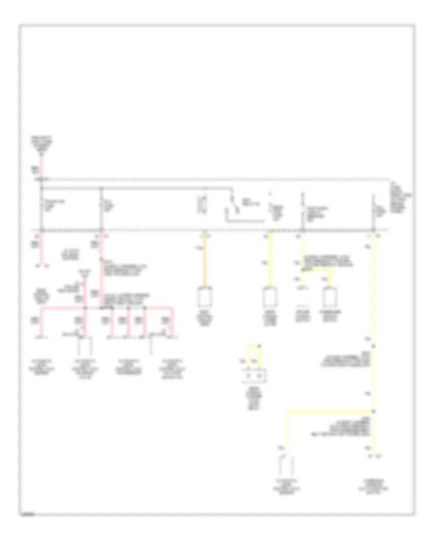
POWER DISTRIBUTION Power Distribution Wiring Diagram (1 of 4) for Chevrolet Uplander LS 2007 List of elements for Power Distribution Wiring Diagram (1 of 4) for Chevrolet Uplander LS 2007: 66 (diagram 1 of 4) (in engine harness 6.5 cm from breakout for tac module, toward c102) s159 (in engine harness, 8 cm from breakout for c101, toward ebcm) s139 12 volt reference A/c cltch fuse 10a A/c cltch relay Abs motor fuse 60a Acc Accessory voltage Batt main 1 fuse 40a (early production, no information available) Batt main 2 fuse 60a Batt main 3 fuse 60a Batt volt Battery Blower motor resistor assembly Body control module (bcm) Crank voltage Crnk relay Electronic brake control module (ebcm) Engine control module (ecm) Fan 1 fuse 30a Fan 1 relay Fan 2 fuse 40a Fan 2 relay Fan 3 relay From batt main 3 fuse b From horn fuse c Frt blwr hi fuse 40a Frt wiper fuse 25a Frt wsw fuse 15a Fuel pump fuse 15a Fuel pump relay Fusible link 242 (14 ga- red) Generator Hi beam relay Horn fuse 15a Horn relay I/p fuse block (right side of dash, behind access panel) Ignition switch Ignition voltage Lo beam relay Lock Pcm etc fuse 15a Pnk Pwr/trn relay Red Rr defog fuse 40a Rr defog relay 30 Run Run rly relay S135 (in engine harness, 5 cm from breakout for starter motor) S160 S279 (in steering column harness, 20 cm from c201) Start Starter motor Strtr sol fuse 40a To 115 vac auxiliary power outlet (diagram 2 of 4) To aux/pwr 12vdc fuse (diagram 2 of 4) To fan 1 fuse (diagram 1 of 4) To frt wsw fuse (diagram 1 of 4) To i/p fuse block (diagram 3 of 4) To i/p fuse block (diagram 4 of 4) Transmission control module (tcm) Underhood fuse block (in underhood compt, above right front wheel well) W/ rear seat electrical receptacle Wpr 1 relay Power Distribution Wiring Diagram (2 of 4) for Chevrolet Uplander LS 2007 List of elements for Power Distribution Wiring Diagram (2 of 4) for Chevrolet Uplander LS 2007: 76 (diagram 1 of 4) (in dash harness, 17.5 cm from cigar lighter) s270 (in engine harness, 10 cm from breakout for c102, toward tac module) s175 (in mobility seat base harness) (in mobility seat interface harness, 9 cm from breakout pnk for c206) s362 (in transmission harness, 9.5 cm from c175) s171 (w/ side air bags) (w/o side air bags) 1-2 shift solenoid (1-2 ss) valve 115 vac auxiliary power outlet 2-3 shift solenoid (2-3 ss) valve A10 Abs fuse 10a Ac/cltch relay Ac/dc invrtr fuse 25a Accessory ac/dc power control module (behind right rear interior body panel) Air bag fuse 10a Apo neutral Apo phase a Automatic transmission Aux/pwr 12vdc fuse 25a Batt + Body control module C175 C277 C279 Cigar lighter Crnk relay Cruise control lever Cruise/switch fuse 2a Electronic brake control module (ebcm) Engine control module (ecm) From ac/dc e From rr defog fuse d From splice 273 (diagram 1 of 4) Front auxiliary power outlet G113 (at engine to transmission stud above g115) G200 (on right side of dash support beam, above dash compt) G301 (on lower left "b" pillar) G400 (on lower right "d" pillar) Ground Hvac control module Hvac/rpa/ cruise fuse 10a I/p fuse block (right side of dash, behind access panel) Ign main relay Inflatable restraint front passenger presence system (pps) module Inflatable restraint passenger air bag on/off indicator Inflatable restraint sensing & diagnostic module (sdm) Inflatable restraint steering wheel coil module Invrtr fuse (diagram 2 of 4) Invtr ctrl Nca Pcm ign fuse 10a Plug inserted switch Pnk Rear auxiliary power outlet Rear object sensor control module Red S155 S246 S331 S373 S374 S404 (w/o passenger side power sliding door) Sit-n-lift seat/ ignition relay Sit-n-lift seat/brake transmission shift interlock relay To ignition main relay (diagram 2 or 4) Torque converter clutch (tcc) solenoid valve Trans sols fuse 10a Transmission control module (tcm) Underhood fuse block (in underhood compt, above right front wheel well) W/ cruise control W/ rear parking assist W/ rear seat electrical receptacle W/ sit-n- lift seat W/o sit-n- lift seat Power Distribution Wiring Diagram (3 of 4) for Chevrolet Uplander LS 2007 List of elements for Power Distribution Wiring Diagram (3 of 4) for Chevrolet Uplander LS 2007: 64 (in mobility seat base harness) s372 (in mobility seat base harness) s376 (right side of dash, behind access panel) i/p fuse block (w/o multimedia) (w/ multimedia) Body control module (bcm) Chmsl bck/up fuse 15a Clstr/ hvac fuse 10a Cnstr/ vent fuse 10a Data link connector (dlc) Digital radio receiver (w/ digital audio system) Digital video disc (dvd) player Driver heated seat relay Driver memory seat module Driver seat adjuster switch Electric sliding door Evaporative emission (evap) canister vent solenoid valve From batt main 2 fuse (diagram 1 of 4) From s160 (diagram 1 or 4) Fuse 25a Fuse 3a Garage door opener Htd/ seats fuse 20a Hvac control module I/p fuse block (right side of dash, behind access panel) Instrument panel cluster (ipc) Int/ lamp fuse 10a Left sliding door module (lsdm) Lt pwr sld dr fuse 40a Onstar fuse 10a Outside rearview mirror switch Passenger heated seat relay Passenger seat adjuster switch Prk lamp relay 28 Prk/lamp fuse 10a Pwr seats circuit breaker 25a Pwr sld dr fuse 15a Pwr/mir ugdo fuse 2a Radio Rdo fuse 15a Red Remote control door lock receiver (rcdlr) Rfa mdls fuse 10a Right sliding door module (rsdm) Rt pwr sld dr fuse 40a S339 (in body harness, 109.2 cm from dvd player) S361 (in mobility seat interface harness, 52 cm from breakout for c314) S370 (in mobility red S411 (in body harness, 6 cm from breakout for left tweeter speaker toward left sliding door module) Seat base harness) Sit-n- lift circuit breaker 8a Sit-n- lift seat fuse block (in sit-n-lift seat base) Sit-n-lift seat module Sit-n-lift seat/door jamb switch relay Stop/ trn fuse 20a Vehicle communication unit (vcu) W/ garage door opener W/ left electric sliding door w/ right W/ memory seat W/ onstar W/ passenger power seat adjuster W/ passenger power seat adjuster w/o sit-n- lift seat W/ rse W/ sit-n- lift seat W/o memory seat Power Distribution Wiring Diagram (4 of 4) for Chevrolet Uplander LS 2007 List of elements for Power Distribution Wiring Diagram (4 of 4) for Chevrolet Uplander LS 2007: 26 (in alc jumper harness, inside vehicle, 16 cm from pass-through) s433 Automatic level control (alc) compressor Automatic level control (alc) inflator air switch Automatic level control (alc) sensor Automatic level control (alc) solenoid valve Body control module (bcm) Driver window switch Elc fuse 20a Elc fuse 25a From batt main 3 fuse (diagram 1 of 4) I/p fuse block (right side of dash, behind access panel) Overhead console multi-function switch Passenger window switch Pwr wndw circuit breaker 25a Rap relay 29 Rear window washer fluid pump relay Rear window wiper motor Rear/ wpr fuse 15a S204 (in dash harness, 10 cm from breakout for c204 toward dash fuse block) S300 (in body harness, 20 cm from breakout for passenger seat belt retractor toward c204) S415 (in body harness, 5 cm from breakout for c405 toward c479) Tan Trunk/lks fuse 15a W/ auto air level control W/ inflator W/ trailer provisions
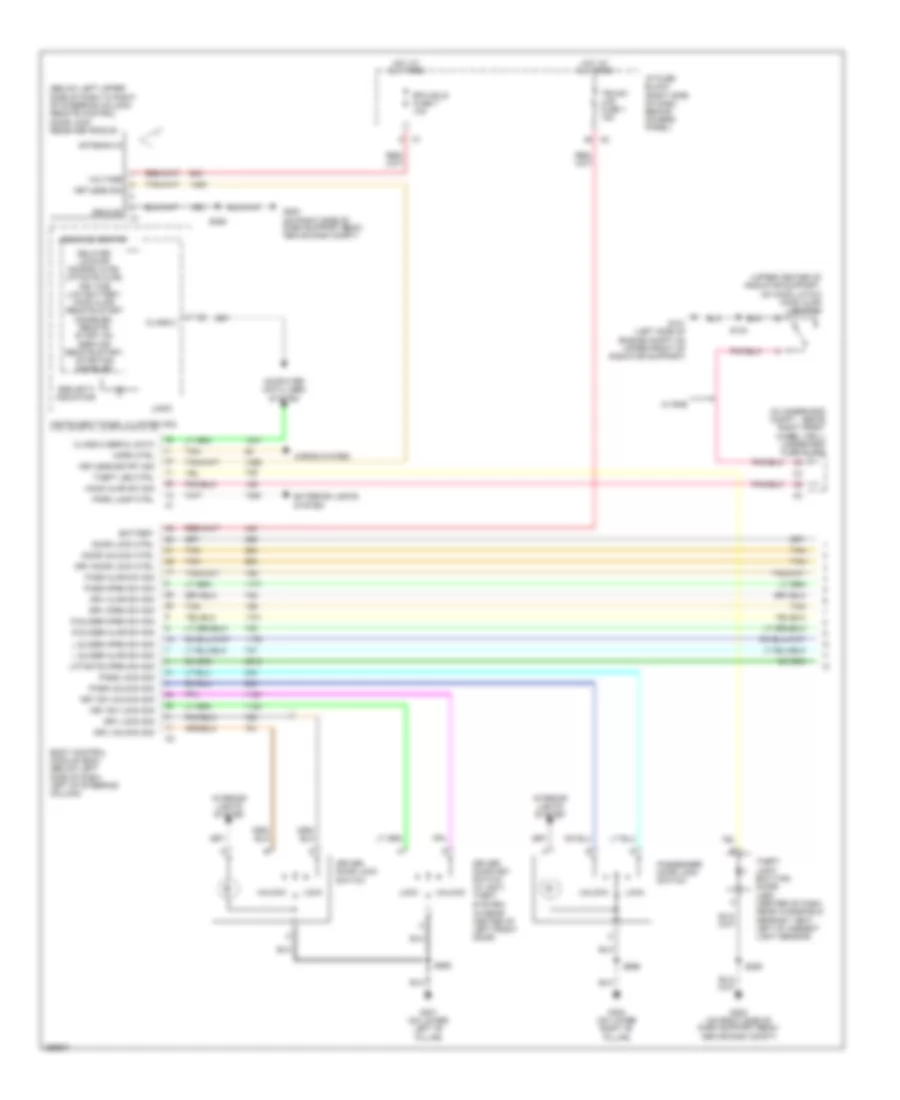
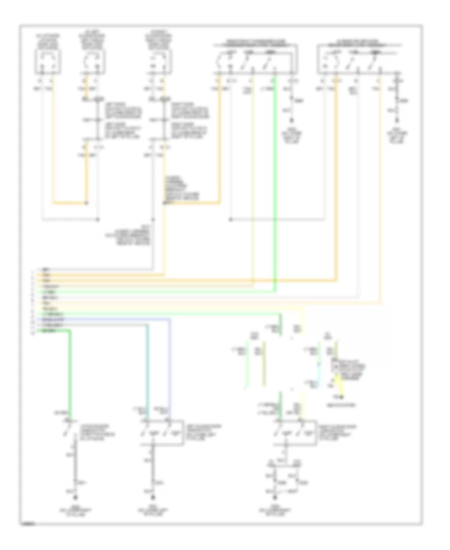
POWER DOOR LOCKS Power Door Locks Wiring Diagram (1 of 2) for Chevrolet Uplander LS 2007 List of elements for Power Door Locks Wiring Diagram (1 of 2) for Chevrolet Uplander LS 2007: 64 (below left upper side of dash to right of steering column) remote control door lock receiver (rcdlr) (in rear center of left front door) (in underhood compt, above right front wheel well) underhood fuse block (upper center of radiator support, on hood latch) hood ajar switch Antenna in Battery Body control module (bcm) (below left side of dash, left of steering column) Class 2 Class 2 serial data Computer data lines system Delayed locking, door(s) ajar, liftgate ajar, key fob low battery, hood ajar, remote start disabled, remote start on, service remote start, starting disabled Door lock ctrl Door unlock ctrl Driver door key switch (w/ anti- theft system) Driver door lock switch Drv ajar sw sig Drv door lock ctrl Drv lock sig Drv open sw sig Drv unlock sig Exterior lights system G101 (left side of engine compt on upper front of radiator support) G200 (on right side of dash support beam, above dash compt) G301 (on lower left "b" pillar) G302 (on lower right "b" pillar) Ground Hood ajar sw sig Horn ctrl Horns system Hot at all times I/p fuse block (right side of dash, behind access panel) Instrument panel cluster (ipc) Interior lights system Key sw lock sig Key sw unlock sig Keyless entry sig Keyless sig L slider ajar sw sig L slider open sw sig Liftgate open sw sig Lock Logic Message center Park lamp ctrl Pass ajar sw sig Pass lock sig Pass open sw sig Pass unlock sig Passenger door lock switch R slider ajar sw sig R slider open sw sig Rfa mdls fuse 7 10a S103 S255 S555 S666 Security indicator Tan Theft led ctrl Theft light emitting diode (led) (center of dash, near windshield defrost vent, left of ambient light sensor) Trunk/ lks fuse 1 15a Unlock Voltage W/ rke Power Door Locks Wiring Diagram (2 of 2) for Chevrolet Uplander LS 2007 List of elements for Power Door Locks Wiring Diagram (2 of 2) for Chevrolet Uplander LS 2007: 40 "d" pillar) (in body harness, 5.5 cm from breakout for c313 toward rear of vehicle) s311 (in left sliding door) left middle door lock actuator (in liftgate) liftgate door lock actuator (in rear driver door) driver door latch assembly (in right sliding door) right middle door lock actuator (rear front passenger door) passenger door latch assembly A c2 Ajar B c1 B c2 C1 a C1 b C2 a C2 d Ctsy G301 (on lower left "b" pillar) G302 (on lower right "b" pillar) G400 (on lower right Left door contact plate c1 (in lower rear of left "b" pillar) Left door contact plate c2 (in lower front of left sliding door) Left sliding door jamb switch (on lower left "c" pillar) Liftgate door jamb switch (in bottom middle of liftgate) Lock Open Right door contact plate c1 (in lower rear of right "b" pillar) Right door contact plate c2 (in lower front of right sliding door) Right sliding door jamb switch (on lower right "c" pillar) S313 (in body harness, 23.5 cm from breakout for c313 toward rear of vehicle) S320 S331 S366 S555 S666 S911 Seats system Sit-n-lift seat diode 3 (in sit-n-lift seat base harness) Tan W/ aqw W/o aqw
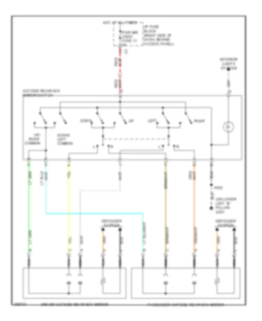
POWER MIRRORS Power Mirrors Wiring Diagram for Chevrolet Uplander LS 2007 List of elements for Power Mirrors Wiring Diagram for Chevrolet Uplander LS 2007: 16 (on lower left "b" pillar) g301 Defogger system Down Down/ left common Driver outside rearview mirror Hot at all times I/p fuse block (right side of dash, behind access panel) Interior lights system Left Nca Outside rearview mirror switch Passenger outside rearview mirror Pwr mir ugdo fuse 11 2a Right S555 Up/ right common
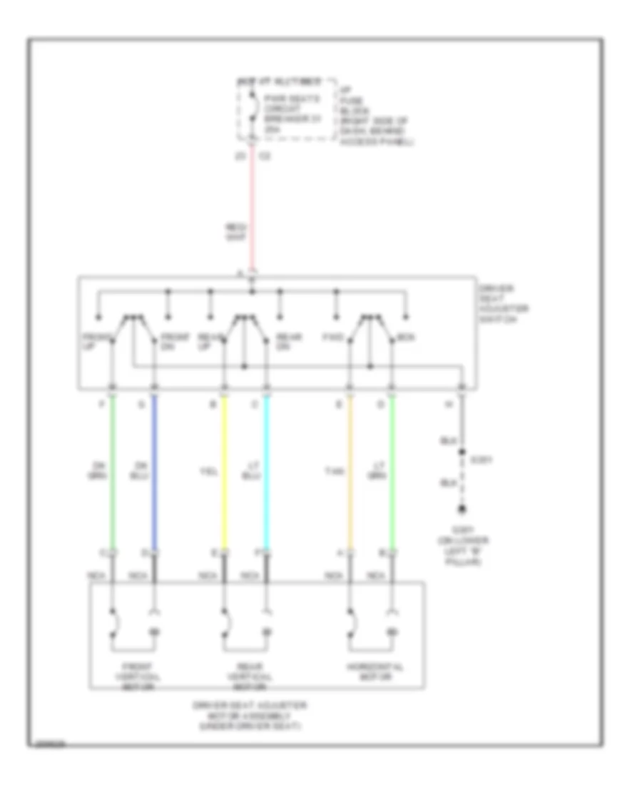
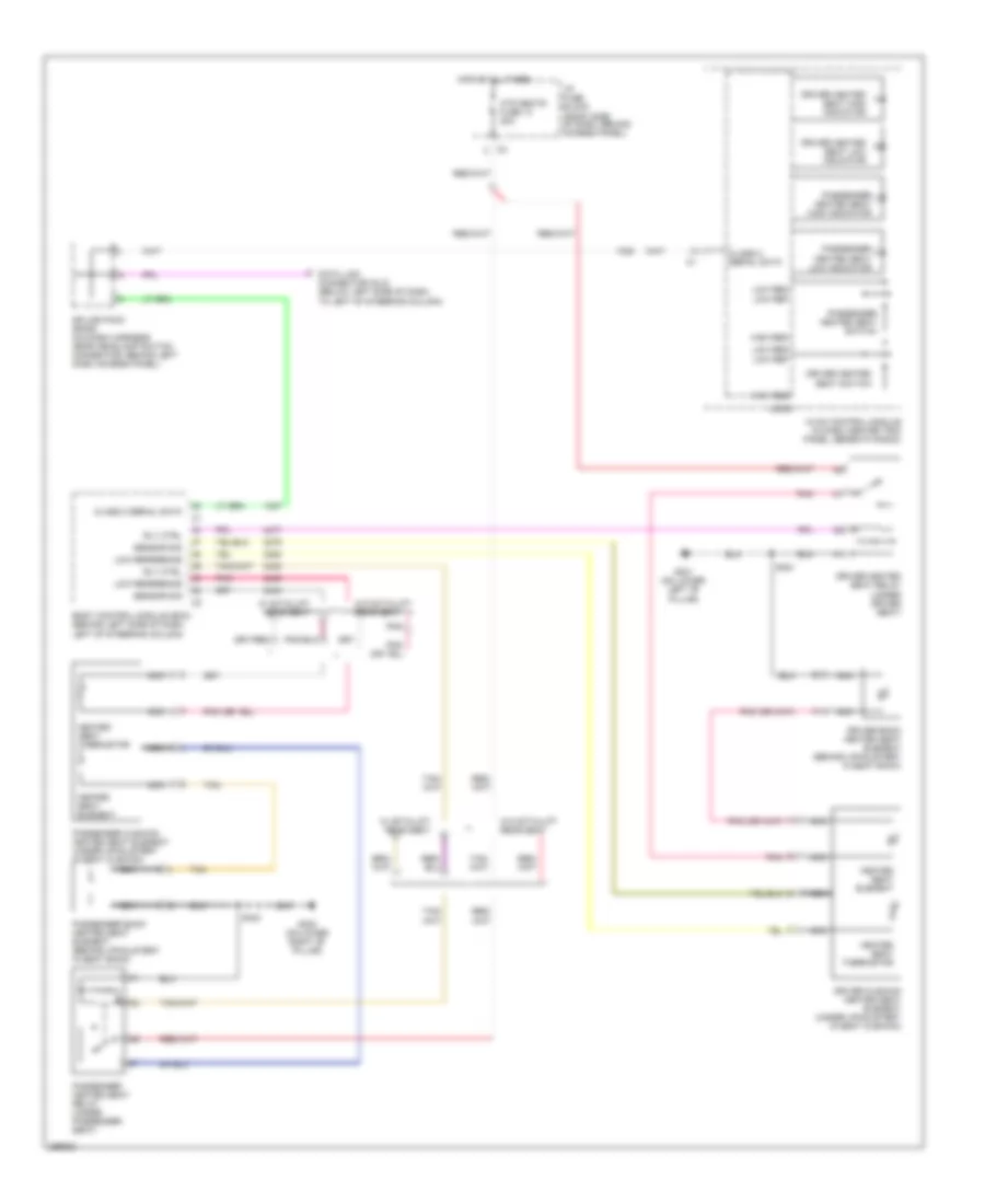
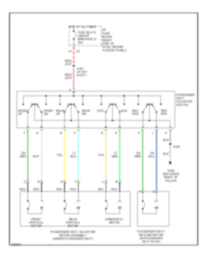
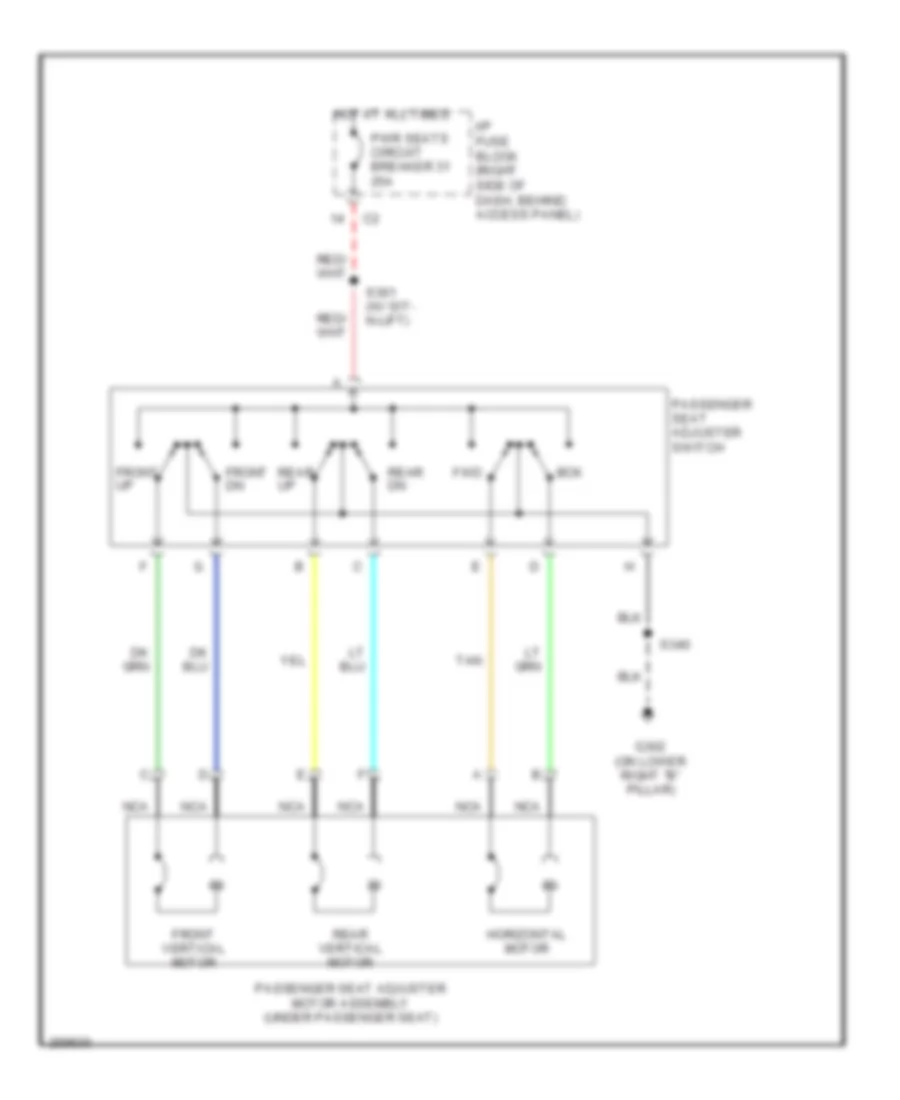
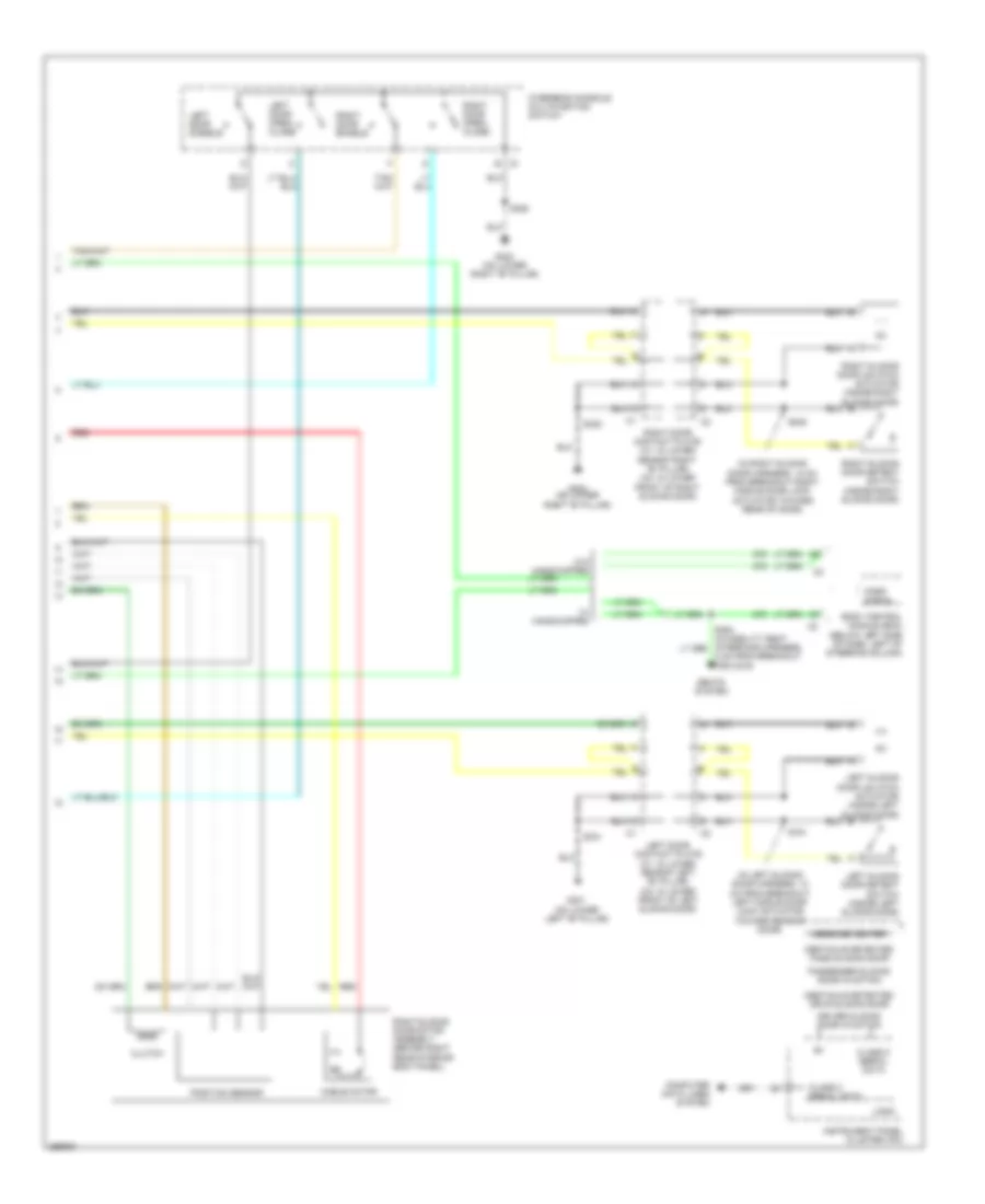
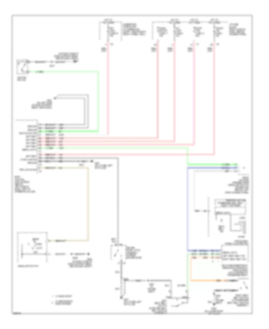
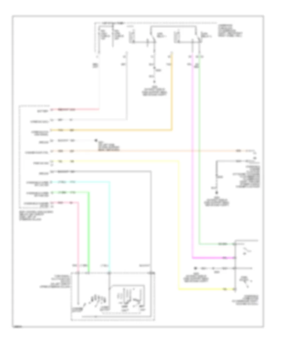
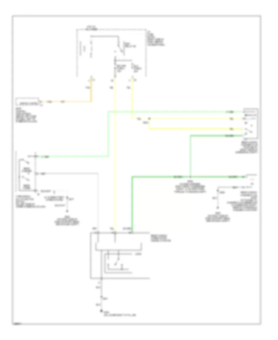
POWER SEATS Driver Seat Wiring Diagram for Chevrolet Uplander LS 2007 List of elements for Driver Seat Wiring Diagram for Chevrolet Uplander LS 2007: 18 Bck Driver seat adjuster motor assembly (under driver seat) Driver seat adjuster switch Front dn Front up Front vertical motor Fwd G301 (on lower left "b" pillar) Horizontal motor Hot at all times I/p fuse block (right side of dash, behind access panel) Nca Pwr seats circuit breaker 31 25a Rear dn Rear up Rear vertical motor S351 Tan Heated Seats Wiring Diagram for Chevrolet Uplander LS 2007 List of elements for Heated Seats Wiring Diagram for Chevrolet Uplander LS 2007: 42 Body control module (bcm) (behind left side of dash, left of steering column) Class 2 serial data Data link connector (dlc) (below left side of dash, to left of steering column) Driver back heated seat element (behind upholstery in seat back) Driver cushion heated seat element (under upholstery in seat cushion) Driver heated seat high indicator Driver heated seat low indicator Driver heated seat relay (under driver seat) Driver heated seat switch Element G301 (on lower left "b" pillar) G302 (on lower right "b" pillar) Heated Heated seat element Heated seat thermistor High req Hot at all times Htd seats fuse 13 20a Hvac control module (in dash center trim panel, beneath radio) I/p fuse block (right side of dash, behind access panel) Logic Low ref Low reference Low req Nca Passenger back heated seat element (behind upholstery in seat back) Passenger cushion heated seat element (under upholstery in seat cushion) Passenger heated seat high indicator Passenger heated seat low indicator Passenger heated seat relay (under passenger seat) Passenger heated seat switch Pnk Rly ctrl S340 S351 Seat Sensor sig Splice pack sp205 (on dash harness near headlamp switch connector, behind left dash access panel) Tan Thermistor W/ sit-n-lift rear seat W/o sit-n-lift rear seat Passenger Full Feature Seat Wiring Diagram for Chevrolet Uplander LS 2007 List of elements for Passenger Full Feature Seat Wiring Diagram for Chevrolet Uplander LS 2007: 22 Bck Front dn Front up Front vertical motor Fwd G302 (on lower right "b" pillar) Horizontal motor Hot at all times I/p fuse block (right side of dash, behind access panel) Nca Passenger seat adjuster motor assembly (under passenger seat) Passenger seat adjuster switch Passenger seat recline motor (in passenger seat back) Pwr seats circuit breaker 31 25a Rear dn Rear up Rear vertical motor Rec bck Rec fwd S340 S361 (w/ sit- n-lift) Tan Passenger Seat Wiring Diagram for Chevrolet Uplander LS 2007 List of elements for Passenger Seat Wiring Diagram for Chevrolet Uplander LS 2007: 19 Bck Front dn Front up Front vertical motor Fwd G302 (on lower right "b" pillar) Horizontal motor Hot at all times I/p fuse block (right side of dash, behind access panel) Nca Passenger seat adjuster motor assembly (under passenger seat) Passenger seat adjuster switch Pwr seats circuit breaker 31 25a Rear dn Rear up Rear vertical motor S340 S361 (w/ sit- n-lift) Tan Sit-N-Lift Seat Wiring Diagram (1 of 2) for Chevrolet Uplander LS 2007 List of elements for Sit-N-Lift Seat Wiring Diagram (1 of 2) for Chevrolet Uplander LS 2007: 63 (in sit-n-lift seat base) Aj08 Aj09 Aje1 Aje2 As01 As04 As05 As06 As07 As14 As16 As17 As19 As20 As21 As28 As29 As30 As36 Battery Circuit breaker 8a Encoder Fuse 1 25a Fuse 2 3a G302 (on lower right "b" pillar) Ground Hot at all times I/p fuse block (right side of dash, behind access panel) Ignition signal Lift lower limit switch Lift lwr limit sw sig Lift mtr dn ctrl Lift mtr up ctrl Lift upper limit switch (in sit-n-lift seat base) Lift uppr limit sw sig Nca Park sw sig Pwr seats circuit breaker 31 25a Red Remote dwn sw sig Remote up sw sig Rr dr open sw sig S361 S370 S372 S379 Shift intrlck rly ctrl Sit-n-lift seat circuit breaker Sit-n-lift seat fuse block Sit-n-lift seat lift motor Sit-n-lift seat module (in sit-n-lift seat base) Splice pack sp370 (in mobility seat base harness) Splice pack sp372 (in mobility seat base harness) Swivel in limit sw sig Swivel inside limit switch Swivel motor Swivel mtr ctrl Swivel out limit sw sig Swivel outside limit switch Swvl mtr hall sen sig Swvl mtr hall sen vlt V02 Sit-N-Lift Seat Wiring Diagram (2 of 2) for Chevrolet Uplander LS 2007 List of elements for Sit-N-Lift Seat Wiring Diagram (2 of 2) for Chevrolet Uplander LS 2007: 31 (in sit-n-lift seat base) sit-n-lift seat/ brake transmission shift interlock relay (in sit-n-lift seat base) sit-n-lift seat/ ignition relay (in sit-n-lift seat base) sit-n-lift seat/door jamb switch relay A/t shift lock control solenoid Body control module (bcm) (below left side of dash, left of steering column) G302 (on lower right "b" pillar) Gnd Hot in on or start Hvac/rpa/ cruise fuse 17 10a I/p fuse block (right c2 side of dash, behind access panel) Pnk Pnp switch sig Power windows system Red Right sliding door jamb switch (on lower right "c" pillar) Rr door open sig S364 (in mobility seat interface harness, 8 cm from breakout for c219) S366 S373 S374 S375 (in mobility seat base harness) S376 (in mobility seat base harness) S377 (in mobility seat base harness) S378 (in mobility seat base harness) Shift lock solenoid Sit-n-lift seat diode 1 (in sit-n-lift seat base harness) Sit-n-lift seat diode 2 (in sit-n-lift seat base harness) Sit-n-lift seat diode 3 (in sit-n-lift seat base harness) Sit-n-lift seat remote Splice pack sp370 (in mobility seat base harness) Underhood fuse block (in underhood compt, above right front wheel well)
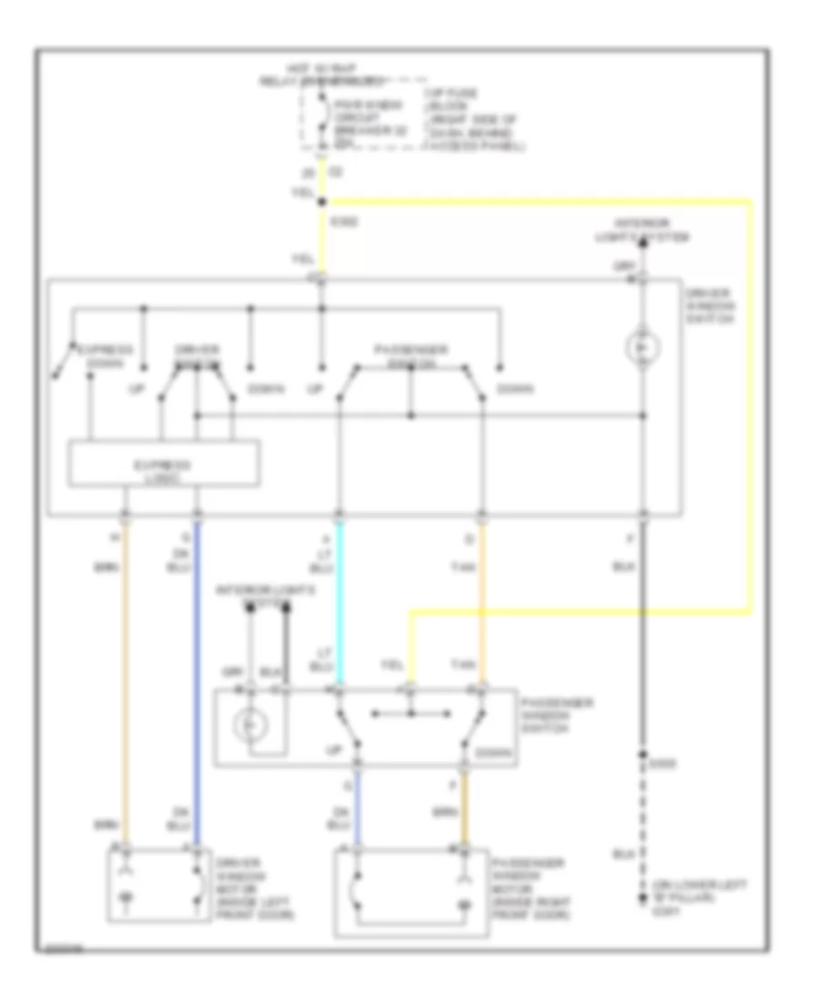
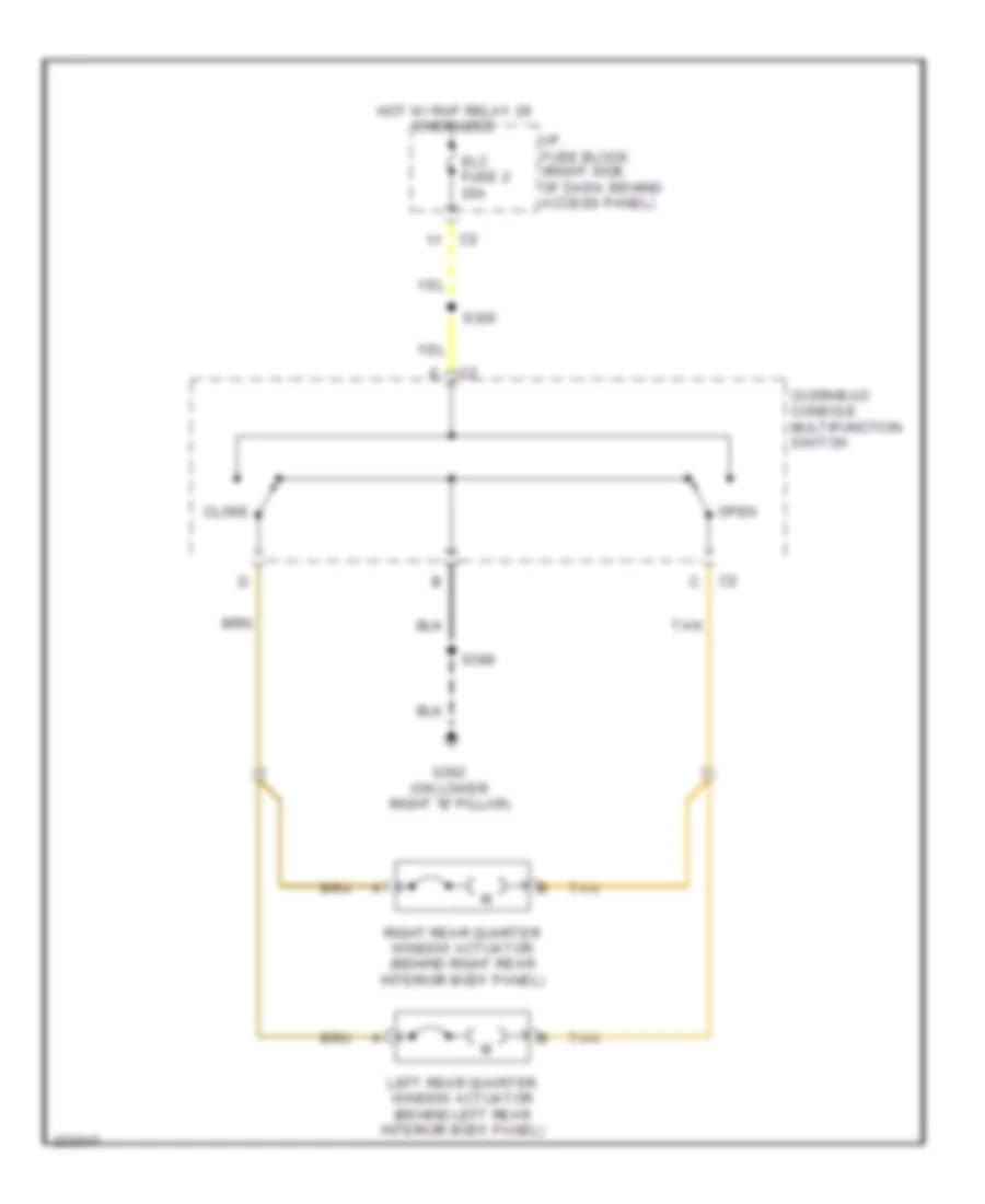
POWER WINDOWS Power Windows Wiring Diagram for Chevrolet Uplander LS 2007 List of elements for Power Windows Wiring Diagram for Chevrolet Uplander LS 2007: 17 (on lower left "b" pillar) g301 Down Driver switch Driver window motor (inside left front door) Driver window switch Express down Express logic Hot w/ rap relay 29 energized I/p fuse block (right side of dash, behind access panel) Interior lights system Passenger switch Passenger window motor (inside right front door) Passenger window switch Pwr wndw circuit breaker 32 25a S302 S555 Tan Rear Quarter Windows Wiring Diagram for Chevrolet Uplander LS 2007 List of elements for Rear Quarter Windows Wiring Diagram for Chevrolet Uplander LS 2007: 12 Close Elc fuse 2 20a G302 (on lower right "b" pillar) Hot w/ rap relay 29 energized I/p fuse block (right side of dash, behind access panel) Left rear quarter window actuator (behind left rear interior body panel) Open Overhead console multifunction switch Right rear quarter window actuator (behind right rear interior body panel) S300 S388 Tan
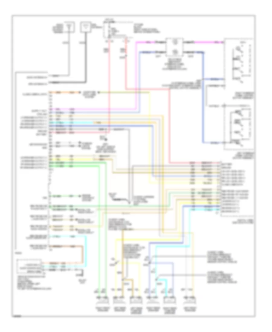
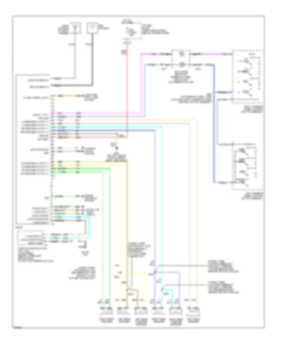
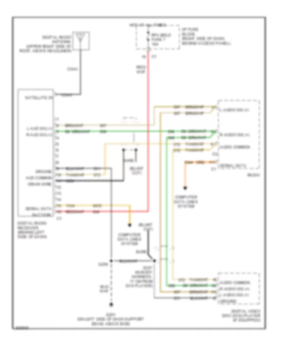
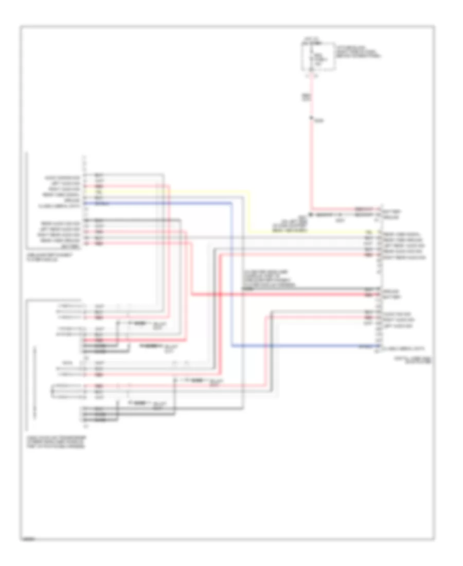
RADIO Radio Wiring Diagram, with Rear Entertainment for Chevrolet Uplander LS 2007 List of elements for Radio Wiring Diagram, with Rear Entertainment for Chevrolet Uplander LS 2007: 95 (in body harn, 10 cm from breakout for right tweeter toward rear object sensor control module) (in body harn, 5 cm from breakout for right tweeter toward rear object sensor control module) (in body harn, main bundle, 10 cm from breakout for branch to dvd player toward c301) (in body harn, main bundle, 5 cm from breakout for branch to dvd player toward c301) (in body harness, 17 cm from dvd player) s337 A10 A11 A12 Am/fm Am/fm antenna in Audio common Audio common sig B10 B11 B12 Bare Battery C277 C279 Class 2 ser data Class 2 serial data Coax Computer data lines system Ctrl sig D nca Digital video disc (dvd) player Drain wire Engine controls system G201 (on left side of dash support beam, above bcm) Gnd Gps antenna Gps antenna in Ground Hot at all times I/p fuse block (right side of dash, behind access panel) Inflatable restraint steering wheel module coil (in steering column) Interior lights system L audio sig (+) Led dimming sig Left front speaker Left rear speaker Left rear tweeter speaker Left steering wheel control switch assembly Lf speaker output (+) Lf speaker output (-) Lr low level sig (+) Lr low level sig (-) Lr speaker output (+) Lr speaker output (-) Lr spkr out (+) Lr spkr out (-) Mute Nca Play Preset R audio sig (+) Radio Radio antenna (on right fender) Rdo fuse 4 15a Rem pb dev aud commn Rem pb dev lt aud sig Rem pb dev rt aud sig Rem pb device audio common sig Rem pb device h Rem pb device j Rem pb device k Rem pb device l audio sig (+) Rf speaker output (+) Rf speaker output (-) Right front speaker Right rear speaker Right rear tweeter speaker Right steering wheel control switch assembly Rr low level sig (+) Rr low level sig (-) Rr speaker output (+) Rr speaker output (-) Rr spkr out (+) Rr spkr out (-) S259 S297 (in steering wheel harn, 15 cm from right steering wheel control switch assembly) S333 S335 S339 S400 S402 Satellite radio circuit Seek down Seek up Set Tan Vehicle communication unit (vcu) (if equipped) (behind upper left side of dash, to left of steering column) Vol down Vol up Vss Radio Wiring Diagram, without Rear Entertainment for Chevrolet Uplander LS 2007 List of elements for Radio Wiring Diagram, without Rear Entertainment for Chevrolet Uplander LS 2007: 74 (in body harn, 10 cm from breakout for right tweeter toward rear object sensor control module) (in body harn, 5 cm from breakout for right tweeter toward rear object sensor control module) (in body harn, main bundle, 10 cm from breakout for branch to dvd player toward c301) (in body harn, main bundle, 5 cm from breakout for branch to dvd player toward c301) A10 A11 A12 Am/fm Am/fm antenna in Audio common Audio common sig B10 B11 B12 Bare Battery C277 C279 Class 2 serial data Coax Computer data lines system Ctrl sig D nca Drain wire Engine controls system G201 (on left side of dash support beam, above bcm) Gnd Gps antenna Gps antenna in Ground Hot at all times I/p fuse block (right side of dash, behind access panel) Inflatable restraint steering wheel module coil (in steering column) Interior lights system L audio sig (+) Led dimming sig Left front speaker Left rear speaker Left rear tweeter speaker Left steering wheel control switch assembly Lf speaker output (+) Lf speaker output (-) Lr speaker output (+) Lr speaker output (-) Mute Nca Play Preset set R audio sig (+) Radio Radio antenna (on right fender) Rdo fuse 4 15a Rf speaker output (+) Rf speaker output (-) Right front speaker Right rear speaker Right rear tweeter speaker Right steering wheel control switch assembly Rr speaker output (+) Rr speaker output (-) S259 S297 (in steering wheel harn, 15 cm from right steering wheel control switch assembly) S333 S335 S400 S402 Satellite radio circuit Seek down Seek up Tan Vehicle communication unit (vcu) (if equipped) (behind upper left side of dash, to left of steering column) Vol down Vol up Vss Satellite Radio Wiring Diagram for Chevrolet Uplander LS 2007 List of elements for Satellite Radio Wiring Diagram for Chevrolet Uplander LS 2007: 26 Aud common Audio common Bare Battery Coax Computer data lines system Digital radio antenna (upper right side of roof, above headliner) Digital radio receiver (behind left side of dash) Digital video disc (dvd) player (if equipped) Drain wire G201 (on left side of dash support beam, above bcm) Ground Hot at all times I/p fuse block (right side of dash, behind access panel) L aud sig (+) L audio sig (+) Nca R aud sig (+) R audio sig (+) Radio Rfa mdls fuse 7 10a S259 S337 (in body harness, 17 cm from dvd player) Satellite in Serial data Tan Video System Wiring Diagram for Chevrolet Uplander LS 2007 List of elements for Video System Wiring Diagram for Chevrolet Uplander LS 2007: 25 (in center headliner console, part of mobile entertainment player module harness) s390 Audio com sig Audio common sig Audio coupling transformer (in rear headliner console, part of phatnoise harness) Bare Battery Class 2 serial data Digital video disc (dvd) player G201 (on left side of dash support beam, above bcm) Ground Hot at all times I/p fuse block (right side of dash, behind access panel) Left audio sig Left rear audio sig Left rear audio sig Mobile entertainment player module Rdo fuse 4 15a Rear audio com sig Rear video ground Rear video signal Red Right audio sig Right rear audio sig S337 S339
SHIFT INTERLOCK
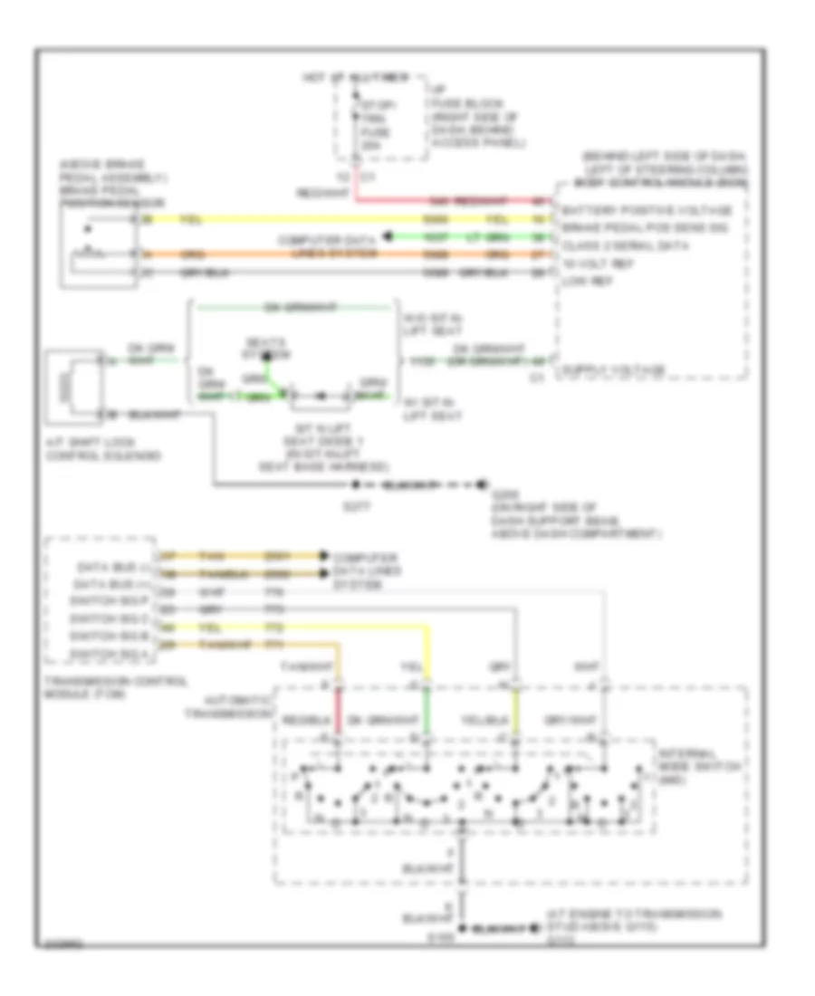
3.9L VIN 1 3.9L VIN 1, Shift Interlock Wiring Diagram for Chevrolet Uplander LS 2007 List of elements for 3.9L VIN 1, Shift Interlock Wiring Diagram for Chevrolet Uplander LS 2007: 30 (above brake pedal assembly) brake pedal position sensor (at engine to transmission stud above g115) g113 (behind left side of dash, left of steering column) body control module (bcm) 10 volt ref A/t shift lock control solenoid Automatic transmission Battery positive voltage Brake pedal pos sens sig Class 2 serial data Computer data lines system Data bus (+) Data bus (-) G200 (on right side of dash support beam, above dash compartment) Hot at all times I/p fuse block (right side of dash, behind access panel) Internal mode switch (ims) Low ref S155 S277 Seats system Sit n lift seat diode 1 (in sit-n-lift seat base harness) Stop/ trn fuse 20a Switch sig a Switch sig b Switch sig c Switch sig p Tan Transmission control module (tcm) W/ sit-n- lift seat W/o sit-n- lift seat
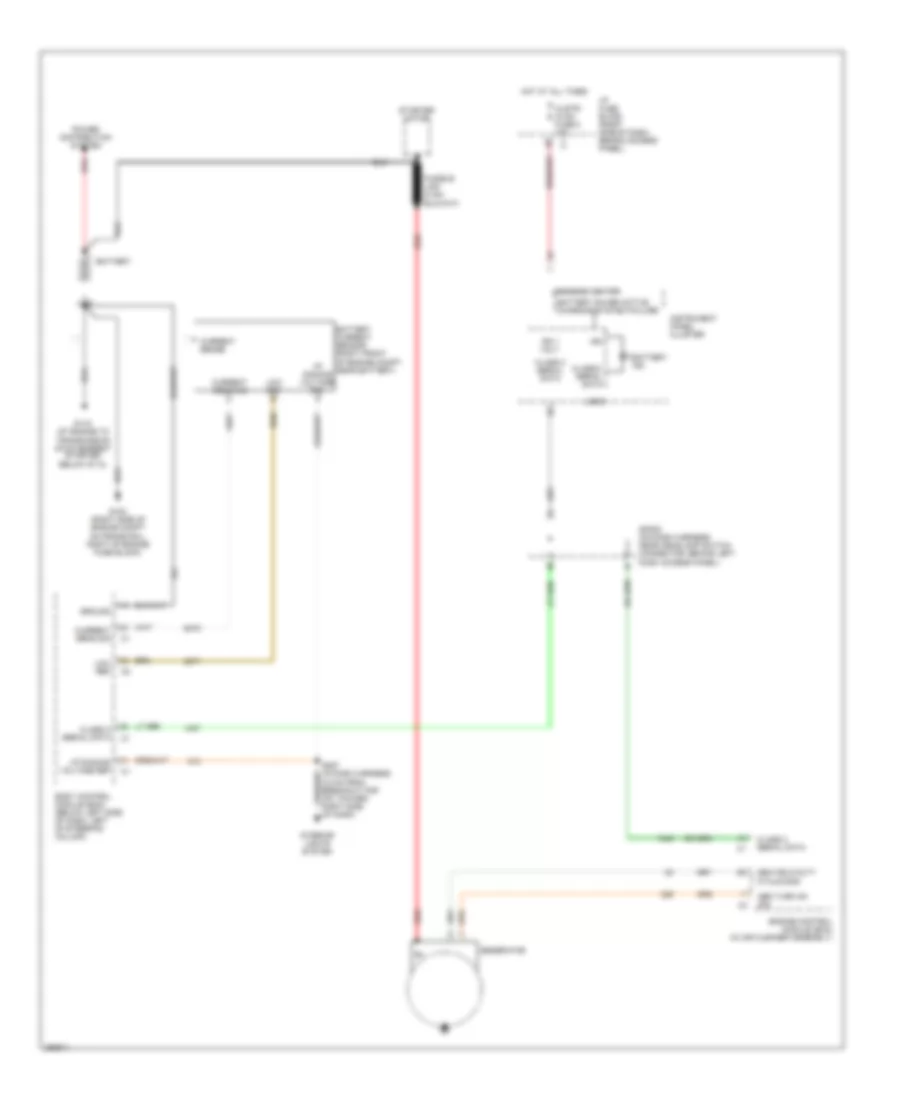
STARTING/CHARGING Charging Wiring Diagram for Chevrolet Uplander LS 2007 List of elements for Charging Wiring Diagram for Chevrolet Uplander LS 2007: 31 Battery Battery current sensor (right front of engine compt, near battery) Battery ind Battery saver active charging system failure Body control module (bcm) (below left side of dash, left of steering column) Class 2 serial data Clstr/ hvac fuse 8 10a Current sens sig Current sense Engine control module (ecm) (in air cleaner assembly) G102 (right side of engine compt on frame rail, right of engine fuse block) G115 (at engine to transmission stud nearest starter below g113) Gen field duty cycle sign Gen turn on sig Generator Ground Hot at all times I/p dimming voltage ref I/p fuse block (right side of dash, behind access panel) Ign Ign 1 volt Instrument panel cluster Interior lights system Logic Low ref Messege center Power distribution system Red S257 (in dash harness, 8.5 cm from breakout for ipc toward right side of dash) Sp205 (on dash harness near headlamp switch connector, behind left dash access panel) Starter motor Starting Wiring Diagram for Chevrolet Uplander LS 2007 List of elements for Starting Wiring Diagram for Chevrolet Uplander LS 2007: 40 12-volt ref Acc Batt volt Battery Body control module (bcm) (below left side of dash, left of steering column) Charging circuit Class 2 serial data Clstr/ hvac fuse 8 10a Crank voltage Crnk relay Disable starting Engine control module (ecm) (in air cleaner assembly) G101 (left side of engine compt, on upper front of radiator support) G102 (right side of engine compt on frame rail, right of engine fuse block) G115 (at engine to transmission stud nearest starter, below g113) Ground distribution system Hood ajar switch (upper center of radiator support, on hood latch) Hood ajar switch sig Hot at all times Hot in start or run I/p fuse block (right side of dash, behind access panel) Ignition 1 voltage Ignition switch Instrument panel cluster Lock Logic Message center Pnk Power distribution system Red Run S103 S279 (in steering column harness, 20 cm from c201) Sp205 (on dash harness near headlamp switch connector, behind left dash access panel) Start Start enable rly ctrl Starter motor Strtr sol fuse 30 40a Underhood fuse block (in underhood compt, above right front wheel well) W/ rke
SUPPLEMENTAL RESTRAINTS Supplemental Restraints Wiring Diagram, with Second Row Side Air Bags (1 of 2) for Chevrolet Uplander LS 2007 List of elements for Supplemental Restraints Wiring Diagram, with Second Row Side Air Bags (1 of 2) for Chevrolet Uplander LS 2007: 57 (above dash compartment) inflatable restraint i/p module (in center hub of steering wheel) inflatable restraint steering wheel module (in driver seat belt retractor assembly) left front seat belt pretensioner (in passenger seat belt retractor assembly) right front seat belt pretensioner (on lower right "b" pillar) g302 C275 Class 2 serial data Computer data lines system G301 (on lower left "b" pillar) G302 (on lower right "b" pillar) Ground I/p stage 1 high I/p stage 1 low I/p stage 2 high I/p stage 2 low Ign 1 vol Inflatable restraint sensing & diagnostic module (sdm) (on floor below passenger seat) Inflatable restraint steering wheel module coil (in steering column) L discriminating sens sig L seat belt pre high L seat belt pre low L seat belt sw sig L side impact sens sig L side impact sens vol Left inflatable restraint front end sensor (on left radiator support) Left inflatable restraint side impact sensing module (sism) (in left "b" pillar) Left seat belt switch Lf side impact high Lf side impact low Low ref Lr side impact high Lr side impact low Nca Occup sens serial data Pin shorting bars engaged when module connector is disconnected from harness (shorting bars are connected between pins: 4-5, 6-7, 8-9, 10-11, 24-25 & 26-27) Pnk R discriminating sens sig R seat belt pre high R seat belt pre low R seat belt sw sig R side impact sens sig R side impact sens vol Rf side impact high Rf side impact low Right inflatable restraint front end sensor (on right radiator support) Right inflatable restraint side impact sensing module (sism) (in right "b" pillar) Right seat belt switch Rr side impact high Rr side impact low S340 (w/ power seat) S351 (w/ power seat) Shorting bar Steer whl stage 1 high Steer whl stage 1 low Steer whl stage 2 high Steer whl stage 2 low Tan Supplemental Restraints Wiring Diagram, with Second Row Side Air Bags (2 of 2) for Chevrolet Uplander LS 2007 List of elements for Supplemental Restraints Wiring Diagram, with Second Row Side Air Bags (2 of 2) for Chevrolet Uplander LS 2007: 44 Air bag fuse 20 10a Air bag ind Air bag off ind Air bag on ind Airbag off ind ctrl Airbag on ind ctrl Belt tens 14v ref Class 2 (sdm) Class 2 serial data Data link connector (dlc) (below left side of dash, to left of steering column) G200 (on right side of dash support beam, above dash compt) G302 (on lower right "b" pillar) Ground Hot w/ ign main relay energized Ignition 1 voltage Illum Inflatable restraint front passenger presence system (pps) module (under passenger seat) Inflatable restraint front passenger presence system (pps) sensor (under upholstery in passenger seat cushion) Inflatable restraint passenger air bag on/off indicator Inflatable restraint passenger seat belt tension retractor sensor (part of passenger seat belt retractor) Instrument panel cluster (ipc) Left inflatable restraint side impact module (in left front seat back) Left rear inflatable restraint side impact module (in left middle seat back) Logic Message center Nca Occupant serial data Passenger seat belt ind Passenger seat belt indicator Passenger seat belt not fastened Pnk Power ind Pps sens 14v ref Pps sens lo ref Pps sens sig Right inflatable restraint side impact module (in right front seat back) Right rear inflatable restraint side impact module (in right middle seat back) S255 Seat belt ind Seat belt tens lo ref Seat belt tens sig Shorting bar Splice pack sp205 (on dash harness near headlamp switch connector, behind left dash access panel) Underhood fuse block (in underhood compt, above right front wheel well) Supplemental Restraints Wiring Diagram, with Side Air Bag (1 of 2) for Chevrolet Uplander LS 2007 List of elements for Supplemental Restraints Wiring Diagram, with Side Air Bag (1 of 2) for Chevrolet Uplander LS 2007: 58 (on lower right "b" pillar) A10 A11 A12 A13 A14 A15 A16 A17 A18 C275 Case ground Class 2 serial data Computer data lines system G302 Ground I/p stage 1 high I/p stage 1 low I/p stage 2 high I/p stage 2 low Ignition 1 Inflatable restraint i/p module (above dash compartment) Inflatable restraint sensing & diagnostic module (sdm) (on floor below passenger seat) Inflatable restraint steering wheel module (in center hub of steering wheel) Inflatable restraint steering wheel module coil (in steering column) L discriminating sig L pretensioner high L pretensioner low L seat belt sw L side impact mod high L side impact mod low L side impact sig L side impact vol Left inflatable restraint front end sensor (on left radiator support) Left inflatable restraint side impact module (in left front seat back) Left inflatable restraint side impact sensing module (sism) (in left "b" pillar) Low ref Nca Occupant serial data Pnk R discriminating sig R pretensioner high R pretensioner low R seat belt sw R side impact mod high R side impact mod low R side impact sig R side impact vol Right inflatable restraint front end sensor (on right radiator support) Right inflatable restraint side impact module (in right front seat back) Right inflatable restraint side impact sensing module (sism) (in right "b" pillar) Shorting bar Steer whl stage 1 high Steer whl stage 1 low Steer whl stage 2 high Steer whl stage 2 low Tan W/ side impact Supplemental Restraints Wiring Diagram, with Side Air Bag (2 of 2) for Chevrolet Uplander LS 2007 List of elements for Supplemental Restraints Wiring Diagram, with Side Air Bag (2 of 2) for Chevrolet Uplander LS 2007: 47 Air bag fuse 20 10a Air bag ind Air bag off ind Air bag off ind ctrl Air bag on ind Air bag on ind ctrl Belt tens 14v ref Class 2 (sdm) Class 2 serial data Data link connector (dlc) (below left side of dash, to left of steering column) G200 (on right side of dash support beam, above dash compt) G301 (on lower left "b" pillar) G302 (on lower right "b" pillar) Ground Hot w/ ign main relay energized Ignition 1 voltage Illum Inflatable restraint front passenger presence system (pps) module (under passenger seat) Inflatable restraint front passenger presence system (pps) sensor (under upholstery in passenger seat cushion) Inflatable restraint passenger air bag on/off indicator Inflatable restraint passenger seat belt tension retractor sensor (part of passenger seat belt retractor) Instrument panel cluster (ipc) Left front seat belt pretensioner (in driver seat belt retractor assembly) Left seat belt switch (in driver seat belt buckle assembly) Logic Message center Nca Nca nca Occupant serial data Passenger seat belt ind Passenger seat belt indicator Passenger seat belt not fastened Pnk Power ind Pps sens 14v ref Pps sens lo ref Pps sens sig Right front seat belt pretensioner (in passenger seat belt retractor assembly) Right seat belt switch (in passenger seat belt buckle assembly) S340 (w/ power seat) (27 cm from breakout for seat belt switch toward seat heater relay) S351 (w/ power seat) (6.5 cm from breakout for seat belt switch toward seat heater relay) Seat belt ind Seat belt tens lo ref Seat belt tens sig Shorting bar Splice pack sp205 (on dash harness near headlamp switch connector, behind left dash access panel) Underhood fuse block (in underhood compt, above right front wheel well)
TRANSMISSION
3.9L VIN 1 3.9L VIN 1, A/T Wiring Diagram (1 of 2) for Chevrolet Uplander LS 2007 List of elements for 3.9L VIN 1, A/T Wiring Diagram (1 of 2) for Chevrolet Uplander LS 2007: 52 (at engine to transmission stud above g115) g113 (in dash harness, 1-2 shift sol 12 v ref 15 cm from breakout for c203 toward right side of dash) s273 2-3 shift sol Acc Accessory volt At iss high sig At iss low sig Battery Body control module (bcm) (below left side of dash, left of steering column) Class 2 serial data Computer data lines system Crank volt Engine controls system Frt wsw fuse 24 15a Ground Hot at all times Ign 1 volt Ignition switch Instrument panel cluster Lock Logic Low ref Message center Pc sol high Pc sol low Pnk Prnd321 Range sw sig a Range sw sig b Range sw sig c Range sw sig p Run S139 (in engine harness, 8 cm from breakout for c101, toward ebcm) S155 (in engine harness, 10 cm from breakout for ecm c1 connector, toward ecm) S279 (in steering column harness, 20 cm from c201) Serial data Sig Start Stop lamp sw Stop lmp volt Tan Tcc pwm sol Tcc release Tft sns sig Transmission control module (tcm) (behind coolant reservoir) Transmission fluid hot Underhood fuse block (in underhood compt, above right front wheel well) Vss high sig Vss low sig 3.9L VIN 1, A/T Wiring Diagram (2 of 2) for Chevrolet Uplander LS 2007 List of elements for 3.9L VIN 1, A/T Wiring Diagram (2 of 2) for Chevrolet Uplander LS 2007: 33 (at engine to transmission stud above g115) g113 (in engine harness, 10 cm from breakout for ecm c1 connector, toward ecm) s155 (lower right rear of underhood compt, mounted to right side of transmission) vehicle speed sensor (vss) assembly 1-2 shift solenoid valve 2-3 shift solenoid valve Acce volt Automatic transmission Automatic transmission fluid temperature sensor Automatic transmission input shaft speed sensor Early production Engine control module (ecm) (in air cleaner assembly) Engine controls system G113 (at engine to transmission stud above g115) Hot at all times I/p fuse block (right c1 side of dash behind access panel) Ign main relay Internal mode switch switch (ims) Late production Park sig Pcm etc fuse 9 15a Pcm ign fuse 14 10a Pnk Pressure control solenoid valve Red S155 (in engine harness, 10 cm from breakout for ecm c1 connector, toward ecm) S159 (in engine harness 6.5 cm from breakout for tac module, toward c102) S171 S175 (in engine harness, 10 cm from breakout for c102, toward tac module) Tan Torque converter clutch release switch Torque converter clutch solenoid valve Trans sols fuse 11 10a Underhood fuse block (in underhood compt, above right front wheel well)
3.9L VIN W 3.9L VIN W, A/T Wiring Diagram (1 of 2) for Chevrolet Uplander LS 2007 List of elements for 3.9L VIN W, A/T Wiring Diagram (1 of 2) for Chevrolet Uplander LS 2007: 52 (at engine to transmission stud above g115) g113 (in dash harness, 1-2 shift sol 12 v ref 15 cm from breakout for c203 toward right side of dash) s273 2-3 shift sol Acc Accessory volt At iss high sig At iss low sig Battery Body control module (bcm) (below left side of dash, left of steering column) Class 2 serial data Computer data lines system Crank volt Engine controls system Frt wsw fuse 24 15a Ground Hot at all times Ign 1 volt Ignition switch Instrument panel cluster Lock Logic Low ref Message center Pc sol high Pc sol low Pnk Prnd321 Range sw sig a Range sw sig b Range sw sig c Range sw sig p Run S139 (in engine harness, 8 cm from breakout for c101, toward ebcm) S155 (in engine harness, 10 cm from breakout for ecm c1 connector, toward ecm) S279 (in steering column harness, 20 cm from c201) Serial data Sig Start Stop lamp sw Stop lmp volt Tan Tcc pwm sol Tcc release Tft sns sig Transmission control module (tcm) (behind coolant reservoir) Transmission fluid hot Underhood fuse block (in underhood compt, above right front wheel well) Vss high sig Vss low sig 3.9L VIN W, A/T Wiring Diagram (2 of 2) for Chevrolet Uplander LS 2007 List of elements for 3.9L VIN W, A/T Wiring Diagram (2 of 2) for Chevrolet Uplander LS 2007: 33 (at engine to transmission stud above g115) g113 (in engine harness, 10 cm from breakout for ecm c1 connector, toward ecm) s155 (lower right rear of underhood compt, mounted to right side of transmission) vehicle speed sensor (vss) assembly 1-2 shift solenoid valve 2-3 shift solenoid valve Acce volt Automatic transmission Automatic transmission fluid temperature sensor Automatic transmission input shaft speed sensor Early production Engine control module (ecm) (in air cleaner assembly) Engine controls system G113 (at engine to transmission stud above g115) Hot at all times I/p fuse block (right c1 side of dash behind access panel) Ign main relay Internal mode switch switch (ims) Late production Park sig Pcm etc fuse 9 15a Pcm ign fuse 14 10a Pnk Pressure control solenoid valve Red S155 (in engine harness, 10 cm from breakout for ecm c1 connector, toward ecm) S159 (in engine harness 6.5 cm from breakout for tac module, toward c102) S171 S175 (in engine harness, 10 cm from breakout for c102, toward tac module) Tan Torque converter clutch release switch Torque converter clutch solenoid valve Trans sols fuse 11 10a Underhood fuse block (in underhood compt, above right front wheel well)
TRUNK, TAILGATE, FUEL DOOR Right & Left Sliding Door Wiring Diagram (1 of 2) for Chevrolet Uplander LS 2007 List of elements for Right & Left Sliding Door Wiring Diagram (1 of 2) for Chevrolet Uplander LS 2007: 50 (on lower left "d" pillar) g401 (on lower right "d" pillar) g400 (w/ left sliding electric) s411 5-volt reference 5-volt rference Battery positive voltage Cable motor Class 2 serial data Clutch Computer data lines system G301 (on lower left "b" pillar) G302 (on lower right "b" pillar) Ground Hot at all times I/p fuse block (right side of dash, behind access panel) Interior lights system Left sldg door open/close sw sig Left sliding door clutch ctrl Left sliding door detent sw sig Left sliding door enable sw sig Left sliding door latch mtr ctrl Left sliding door module (lsdm) (behind left rear interior body panel) Left sliding door motor assembly (behind left rear interior body panel) Left sliding door mtr close ctrl Left sliding door mtr open ctrl Left sliding door open/ close switch (on left "b" pillar) Left sliding door sens 1 sig Left sliding door sens 2 sig Low reference Low refrence Lt pwr sld dr fuse 24 40a Park/neutral position park sig Position sensor Pwr sld dr fuse 21 15a Red Right sldg door open/close sw sig Right sliding door clutch ctrl Right sliding door detent sw sig Right sliding door enable sw sig Right sliding door latch mtr ctrl Right sliding door module (rsdm) (behind right rear interior body panel) Right sliding door mtr close ctrl Right sliding door mtr open ctrl Right sliding door open/ close switch (on right "b" pillar) Right sliding door sens 1 sig Right sliding door sens 2 sig Rt pwr sld dr fuse 25 40a S331 S380 Tan Right & Left Sliding Door Wiring Diagram (2 of 2) for Chevrolet Uplander LS 2007 List of elements for Right & Left Sliding Door Wiring Diagram (2 of 2) for Chevrolet Uplander LS 2007: 42 (in left sliding door harness, 12 cm from breakout left middle door lock actuator toward rear of door) (in right sliding door harness, 12 cm from breakout right middle door lock actuator toward rear of door) (on lower left "b" pillar) 8 cm from breakout for c219) Body control module (bcm) (below left side of dash, left of steering column) C1 b Cable motor Class 2 serial data Clutch Computer data lines system Driver sliding door in motion G301 G302 (on lower right "b" pillar) Instrument panel cluster (ipc) Left door contact plate (c1: in lower rearof left "b" pillar) (c2: in lower front of left sliding door) Left door disable Left door open/ close Left sliding door detent switch (inside left sliding door) Left sliding door unlatch actuator (inside left sliding door) Logic Message center Obstacle detected drvr sliding door Obstacle detected pass sliding door Overhead console multifunction switch Park signal Passenger sliding door in motion Position sensor Red Right door contact plate (c1: in lower rearof right "b" pillar) (c2: in lower front of right sliding door) Right door enable Right door open/ close Right sliding door detent switch (inside right sliding door) Right sliding door motor assembly (behind right rear interior body panel) Right sliding door unlatch actuator (inside right sliding door) S320 S331 S388 S751 S848 Seats system W/ handicapped W/o handicapped
WARNING SYSTEMS Warning Systems Wiring Diagram for Chevrolet Uplander LS 2007 List of elements for Warning Systems Wiring Diagram for Chevrolet Uplander LS 2007: 51 (on right side of dash support beam, above dash compt) g200 A11 A14 A16 Auto Battery Body control module (bcm) (below left side of dash, left of steering column) Chime Chmsl bck/up fuse 17 15a Driver door latch assembly (in rear driver door) Frt wsw fuse 24 15a G200 (on right side of dash support beam, above dash compt) G201 (on left side of dash support beam, above bcm) G301 (on lower left "b" pillar) G302 (on lower right "b" pillar) Ground Head Headlamp switch Hot at all times I/p fuse block (right side of dash, behind access panel) Ignition sw sig Ignition switch Inflatable restraint sensing & diagnostic module (sdm) (on floor below passenger seat) Instrument panel cluster (ipc) Int/ lamp fuse 5 10a Left seat belt sw Left seat belt switch (in driver seat belt buckle assembly) Lf dr ajar sig Logic Message center Nca Off Park Passenger seat belt is not fastened Prk lmp on sig Right seat belt sw Right seat belt switch (in passenger seat belt buckle assembly) S255 S277 S331 S340 (w/ power seat) S351 (w/ power seat) S555 Seat belt ind Serial data Sp205 (on dash harness near headlamp switch connector, behind left dash access panel) Stop/ trn fuse 12 20a Trunk/ lks fuse 1 15a Underhood fuse block (in underhood compt, above right front wheel well) W/ second row side air bags W/ side impact
WIPER/WASHER Front Wiper/Washer Wiring Diagram for Chevrolet Uplander LS 2007 List of elements for Front Wiper/Washer Wiring Diagram for Chevrolet Uplander LS 2007: 34 Battery Body control module (bcm) (below left side of dash, left of steering column) D2 d1 Frt wpr fuse 28 25a Frt wsw fuse 24 15a G200 (on right side of dash support beam, above dash compt) G201 (on left side of dash support beam, above bcm) Ground H c3 High Hot at all times Int Low Mist Off Park sw sig Park switch Pnk S200 Tan Turn signal/ multi-function switch (on left side of upper steering column) Underhood fuse block (in underhood compt, above right front wheel well) Washer pump ctrl Washer switch Windshield washer fluid pump (attached to washer fluid reservoir in underhood compt, forward of rear window washer fluid pump) Windshield washer sw sig c3 Windshield wiper motor (in underhood compt, mounted on cowl) Windshield wiper sw high sig Windshield wiper sw low sig Wiper sw sig 2 Wiper switch Wiper switch high signal Wpr relay 1 Wpr relay 2 Rear Wiper/Washer Wiring Diagram for Chevrolet Uplander LS 2007 List of elements for Rear Wiper/Washer Wiring Diagram for Chevrolet Uplander LS 2007: 23 Body control module (bcm) (below left side of dash, left of steering column) Elc fuse 2 20a G200 (on right side of dash support beam, above dash compt) G400 (on lower right "d" pillar) Hot at all times I/p fuse block (right side of dash, behind access panel) Logic Rap relay 29 Rap rly cntrl Rear washer Rear window washer fluid pump (attached to washer fluid reservoir in underhood compt, rear of windshield washer fluid pump) Rear window washer fluid pump relay (right rear of underhood compt) Rear window wiper motor (inside liftgate) Rear wiper Rr wpr fuse 3 15a S200 S204 S206 (in dash harness, right front passenger compt, 10 cm from pass through to engine compt) S277 S911 Tan Turn signal/ multi-function switch (on left side of upper steering column) W/ intermittent wiper system