Diagram sections — 25 (53 total)
AIR CONDITIONING ANTI-LOCK BRAKES ANTI-THEFT BODY COMPUTER COMPUTER DATA LINES COOLING FAN CRUISE CONTROL ENGINE PERFORMANCE EXTERIOR LIGHTS GROUND DISTRIBUTION HEADLIGHTS HORN INSTRUMENT CLUSTER INTERIOR LIGHTS POWER DISTRIBUTION POWER DOOR LOCKS POWER MIRRORS POWER SEATS POWER WINDOWS RADIO STARTING/CHARGING SUPPLEMENTAL RESTRAINTS TRANSMISSION WARNING SYSTEMS WIPER/WASHER
AIR CONDITIONING
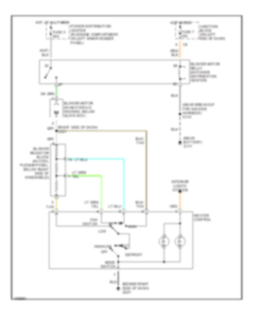
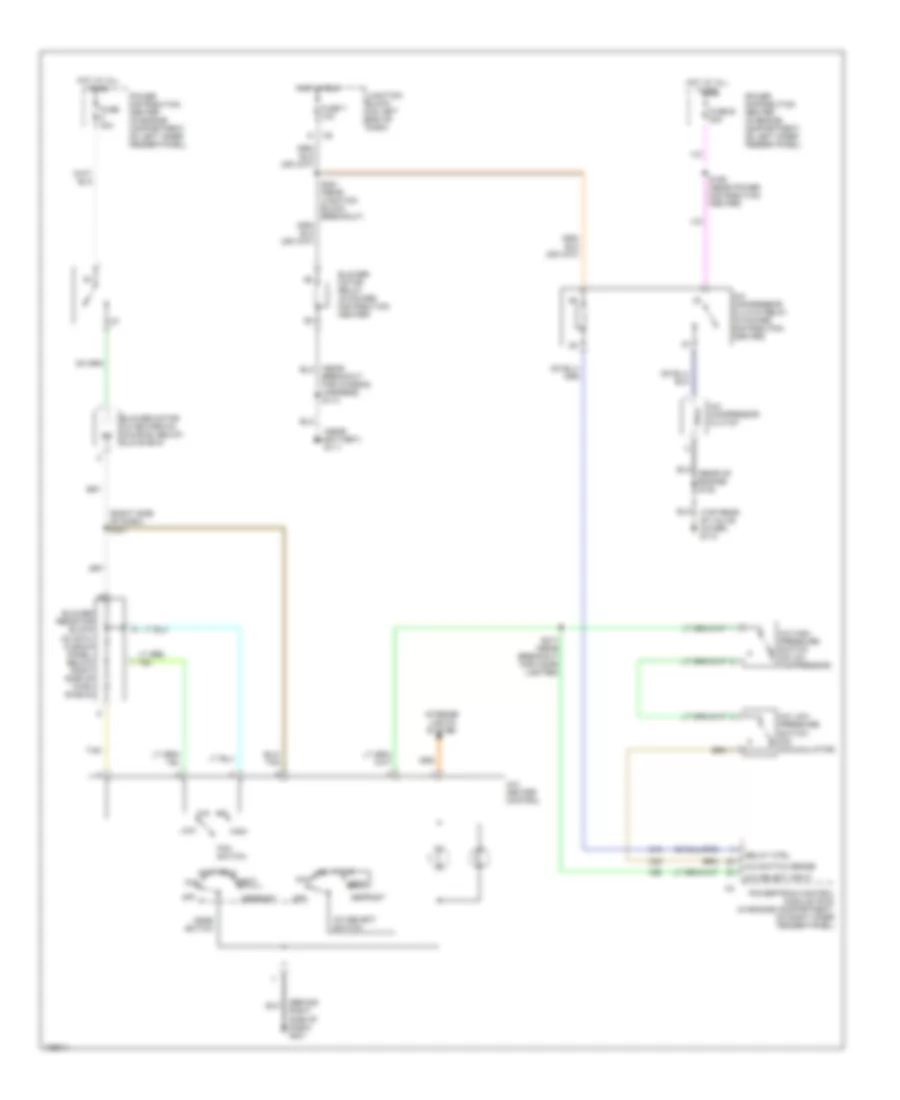
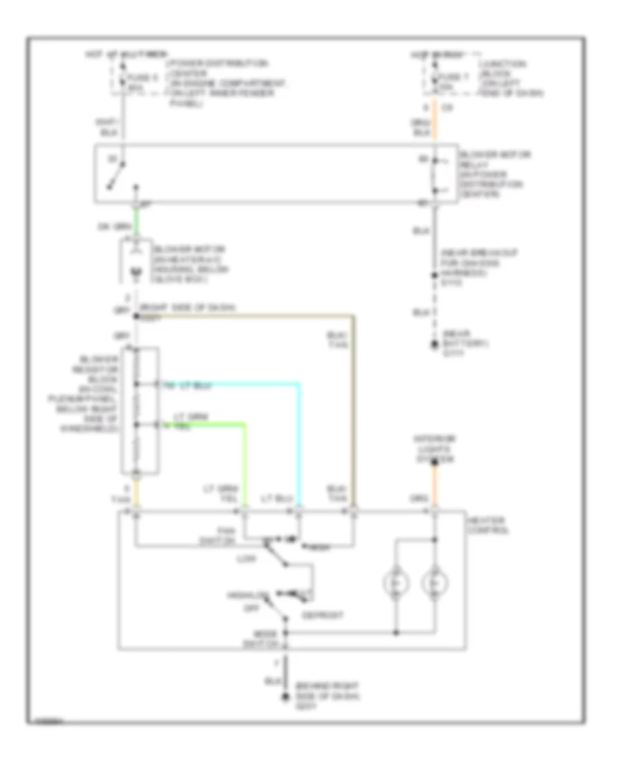
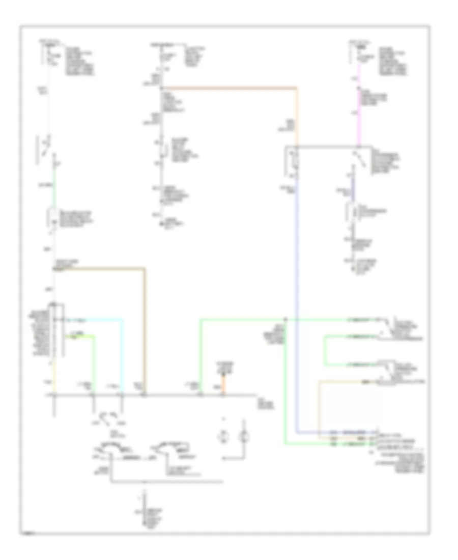
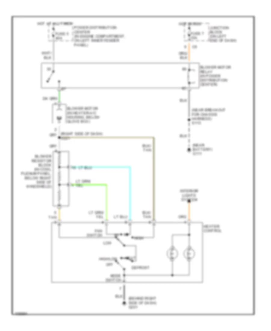
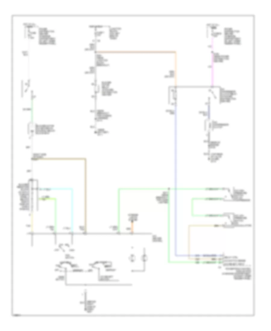
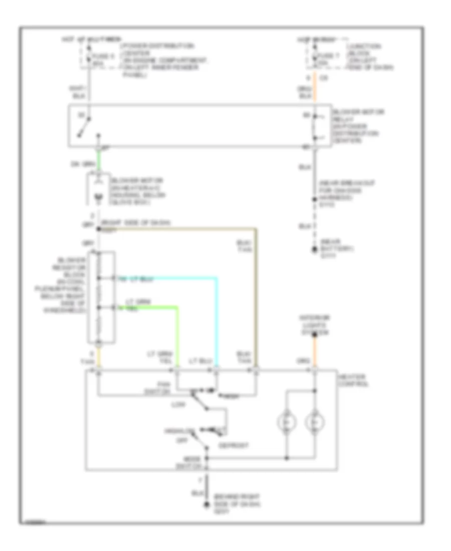
2.5L 2.5L, Manual A/C Wiring Diagram for Dodge Dakota 1999 List of elements for 2.5L, Manual A/C Wiring Diagram for Dodge Dakota 1999: 51 (behind right side of dash) g201 (near battery) g111 (near right headlamp breakout) s109 (right front inner fender) g101 (right side of dash) s221 (top rear of valve cover) g114 A/c compressor clutch A/c compressor clutch relay (in power distribution center) A/c high pressure switch (on a/c compressor) A/c low pressure switch (on accumulator) A/c select input A/c select switch A/c switch sense A/c- heater control Blower motor (in heater-a/c housing, below glove box) Blower motor relay (in power distribution center) Blower resistor block (in cowl plenum panel, below right side of wind- shield) Breakout for chassis harness) s113 C13 C20 C27 C90 Coolant fan motor (behind center lower radiator) Coolant fan relay (in power distribution center) Defrost Fan switch Fuse 10a Fuse 2 30a Fuse 40a Fuse 7 10a Fuse e 20a Heat Hi/lo a/c High Hot at all times Hot in run Hot in run or start Interior lights system J/c 1 (in power distribution center Junction block (on left end of dash) Low Max Mode switch Off Power distribution center (in engine compartment, on left inner fender panel) Powertrain control module (pcm) (in engine compartment, on right inner fender panel) Relay ctrl S159 (near power distribution center) S217 (near breakout for cigar lighter) S251 (near junction block breakout) Tan Heater Wiring Diagram for Dodge Dakota 1999 List of elements for Heater Wiring Diagram for Dodge Dakota 1999: 24 low (behind right side of dash) g201 (near battery) g111 (near breakout for chassis harness) s113 Blower motor (in heater-a/c housing, below glove box) Blower motor relay (in power distribution center) Blower resistor block (in cowl plenum panel, below right side of windshield) Defrost Fan switch Fuse 5 40a Fuse 7 10a Heat Heater control High High/low Hot at all times Hot in run Interior lights system Junction block (on left end of dash) Mode switch Off Power distribution center (in engine compartment, on left inner fender panel) S221 Tan
3.9L 3.9L, Manual A/C Wiring Diagram for Dodge Dakota 1999 List of elements for 3.9L, Manual A/C Wiring Diagram for Dodge Dakota 1999: 42 (behind right side of dash) g201 (near battery) g111 (right side of dash) s221 (top rear of valve cover) g110 A/c compressor clutch A/c compressor clutch relay (in power distribution center) A/c high pressure switch (on a/c compressor) A/c low pressure switch (on accumulator) A/c select input A/c select switch A/c switch sense A/c- heater control Blower motor (in heater-a/c housing, below glove box) Blower motor relay (in power distribution center) Blower resistor block (in cowl plenum panel, below right side of wind- shield) Breakout for chassis harness) s113 C13 C20 C90 Defrost Fan switch Fuse 40a Fuse 7 10a Fuse e 20a Heat Hi/lo a/c High Hot at all times Hot in run Interior lights system Junction block (on left end of dash) Low Max Mode switch Off Power distribution center (in engine compartment, on left inner fender panel) Powertrain control module (pcm) (in engine compartment, on right inner fender panel) Relay ctrl S159 (near power distribution center) S217 (near breakout for cigar lighter) S251 (near junction block breakout) Tan Heater Wiring Diagram for Dodge Dakota 1999 List of elements for Heater Wiring Diagram for Dodge Dakota 1999: 24 low (behind right side of dash) g201 (near battery) g111 (near breakout for chassis harness) s113 Blower motor (in heater-a/c housing, below glove box) Blower motor relay (in power distribution center) Blower resistor block (in cowl plenum panel, below right side of windshield) Defrost Fan switch Fuse 5 40a Fuse 7 10a Heat Heater control High High/low Hot at all times Hot in run Interior lights system Junction block (on left end of dash) Mode switch Off Power distribution center (in engine compartment, on left inner fender panel) S221 Tan
5.2L 5.2L, Manual A/C Wiring Diagram for Dodge Dakota 1999 List of elements for 5.2L, Manual A/C Wiring Diagram for Dodge Dakota 1999: 42 (behind right side of dash) g201 (near battery) g111 (right side of dash) s221 (top rear of valve cover) g110 A/c compressor clutch A/c compressor clutch relay (in power distribution center) A/c high pressure switch (on a/c compressor) A/c low pressure switch (on accumulator) A/c select input A/c select switch A/c switch sense A/c- heater control Blower motor (in heater-a/c housing, below glove box) Blower motor relay (in power distribution center) Blower resistor block (in cowl plenum panel, below right side of wind- shield) Breakout for chassis harness) s113 C13 C20 C90 Defrost Fan switch Fuse 40a Fuse 7 10a Fuse e 20a Heat Hi/lo a/c High Hot at all times Hot in run Interior lights system Junction block (on left end of dash) Low Max Mode switch Off Power distribution center (in engine compartment, on left inner fender panel) Powertrain control module (pcm) (in engine compartment, on right inner fender panel) Relay ctrl S159 (near power distribution center) S217 (near breakout for cigar lighter) S251 (near junction block breakout) Tan Heater Wiring Diagram for Dodge Dakota 1999 List of elements for Heater Wiring Diagram for Dodge Dakota 1999: 24 low (behind right side of dash) g201 (near battery) g111 (near breakout for chassis harness) s113 Blower motor (in heater-a/c housing, below glove box) Blower motor relay (in power distribution center) Blower resistor block (in cowl plenum panel, below right side of windshield) Defrost Fan switch Fuse 5 40a Fuse 7 10a Heat Heater control High High/low Hot at all times Hot in run Interior lights system Junction block (on left end of dash) Mode switch Off Power distribution center (in engine compartment, on left inner fender panel) S221 Tan
5.9L 5.9L, Manual A/C Wiring Diagram for Dodge Dakota 1999 List of elements for 5.9L, Manual A/C Wiring Diagram for Dodge Dakota 1999: 42 (behind right side of dash) g201 (near battery) g111 (right side of dash) s221 (top rear of valve cover) g110 A/c compressor clutch A/c compressor clutch relay (in power distribution center) A/c high pressure switch (on a/c compressor) A/c low pressure switch (on accumulator) A/c select input A/c select switch A/c switch sense A/c- heater control Blower motor (in heater-a/c housing, below glove box) Blower motor relay (in power distribution center) Blower resistor block (in cowl plenum panel, below right side of wind- shield) Breakout for chassis harness) s113 C13 C20 C90 Defrost Fan switch Fuse 40a Fuse 7 10a Fuse e 20a Heat Hi/lo a/c High Hot at all times Hot in run Interior lights system Junction block (on left end of dash) Low Max Mode switch Off Power distribution center (in engine compartment, on left inner fender panel) Powertrain control module (pcm) (in engine compartment, on right inner fender panel) Relay ctrl S159 (near power distribution center) S217 (near breakout for cigar lighter) S251 (near junction block breakout) Tan Heater Wiring Diagram for Dodge Dakota 1999 List of elements for Heater Wiring Diagram for Dodge Dakota 1999: 24 low (behind right side of dash) g201 (near battery) g111 (near breakout for chassis harness) s113 Blower motor (in heater-a/c housing, below glove box) Blower motor relay (in power distribution center) Blower resistor block (in cowl plenum panel, below right side of windshield) Defrost Fan switch Fuse 5 40a Fuse 7 10a Heat Heater control High High/low Hot at all times Hot in run Interior lights system Junction block (on left end of dash) Mode switch Off Power distribution center (in engine compartment, on left inner fender panel) S221 Tan
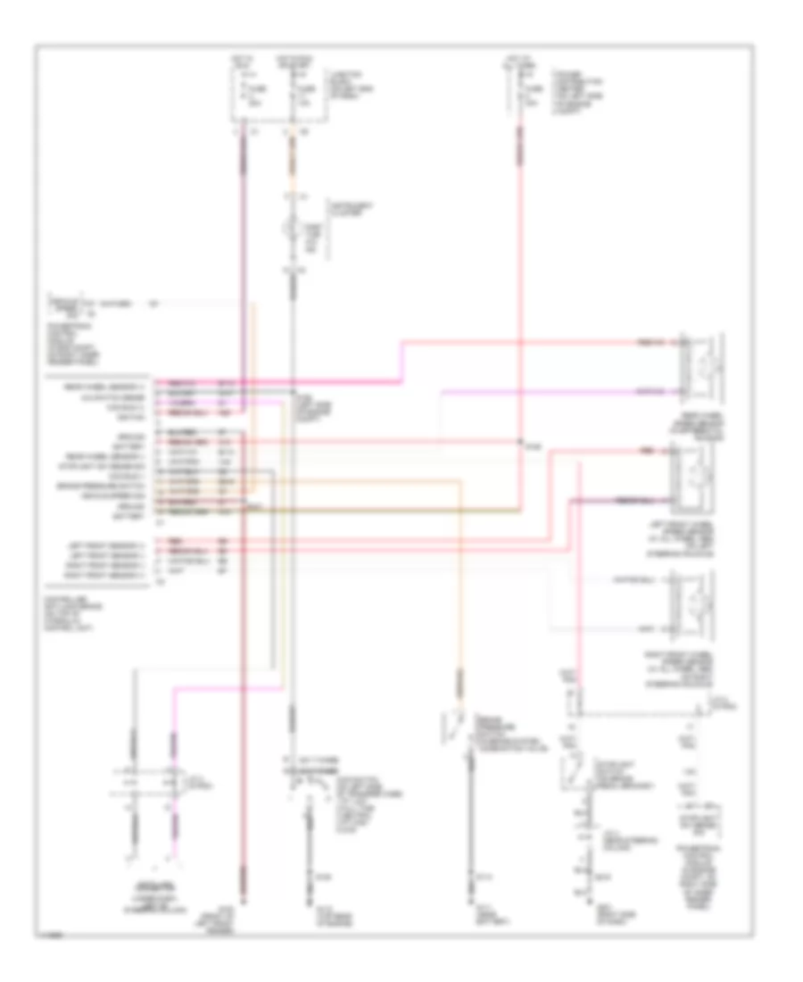
ANTI-LOCK BRAKES Anti-lock Brake Wiring Diagrams for Dodge Dakota 1999 List of elements for Anti-lock Brake Wiring Diagrams for Dodge Dakota 1999: 59 (231 t-case) (242 t-case) (under dash, left of steering column) 4wd switch (on left side of transfer case) 1 pt low 2 full time 3 neutral 4 pt high 5 2wd 4x4 switch sense A10 A20 B113 B114 B218 Battery Brake pressure switch Brake pressure switch (in brake system combination valve) Ccd bus (+) Ccd bus (-) Controller anti-lock brake (on top of hydraulic control unit) Data link connector Fuse 10a Fuse 20a Fuse 40a G100 (front of left front fender) G107 G111 (near battery) G115 (top rear of engine) G201 (right side of dash) Ground Hot at all times Hot in run Hot in run or start Ignition Instrument cluster J/c 2 (in pdc) J/c 3 (in pdc) J/c 4 (near steering column) Junction block (on left end of dash) Left front sensor (+) Left front sensor (-) Left front wheel speed sensor (w/ all wheel abs) (on left steering knuckle) Part time 4x4 ind Power distribution center (on left side of engine compt) Powertrain control module (in eng compt, on right inner fender panel) Powertrain control module (in engine compt, on right side of inner fender panel) Rear wheel sensor (+) Rear wheel sensor (-) Rear wheel speed sensor (in differential housing) Red Right front sensor (+) Right front sensor (-) Right front wheel speed sensor (w/ all wheel abs) (on right steering knuckle) S108 S113 S126 S127 S156 (left side of engine compt) S216 Stoplight sw sense sig Stoplight switch (on brake pedal bracket) V40 Vehicle speed sig
ANTI-THEFT Anti-theft Wiring Diagram for Dodge Dakota 1999 List of elements for Anti-theft Wiring Diagram for Dodge Dakota 1999: 62 (right front corner of engine compt) s125 Ccd bus (+) Ccd bus (-) Central timer module (behind right side of dash, near glove box) Datalink connector (under dash, left of steering column) Disarm sense Door ajar sense Door lk sense Door unlk sense F12 F35 Fuse 10a Fuse 20a Fuse e 20a Fused b(+) Fused ign G101 (right front inner fender) G16 G201 (right side of dash) G50 G52 G69 Ground Hdlmp relay ctrl Headlights system (headlamp flasher relay) High note horn (right front fender) Horn relay (in power distribution center) Horn relay ctrl Horns system (horn switch) Hot at all times Hot in run or acc Hot in run or start Instrument cluster Interior lights system J/c 3 (left side of dash) Junction block (on left end of dash) Left door disarm switch Left door jamb switch Lock Low note horn (right front fender) P37 P38 Power distribution center (in engine compt, on left inner fender panel) Powertrain control module (in engine compt, on right inner fender panel) Red Right door disarm switch Right door jamb switch Right power window/door lock switch S109 S159 S170 S203 (between breakouts to instrument cluster) S210 (center of dash) S218 (right side of dash) S223 S301 S334 S335 S403 Unlock Vtss ind ctrl Vtss lamp
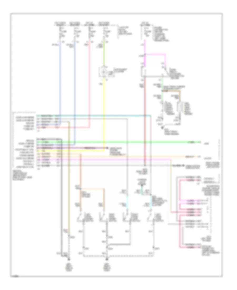
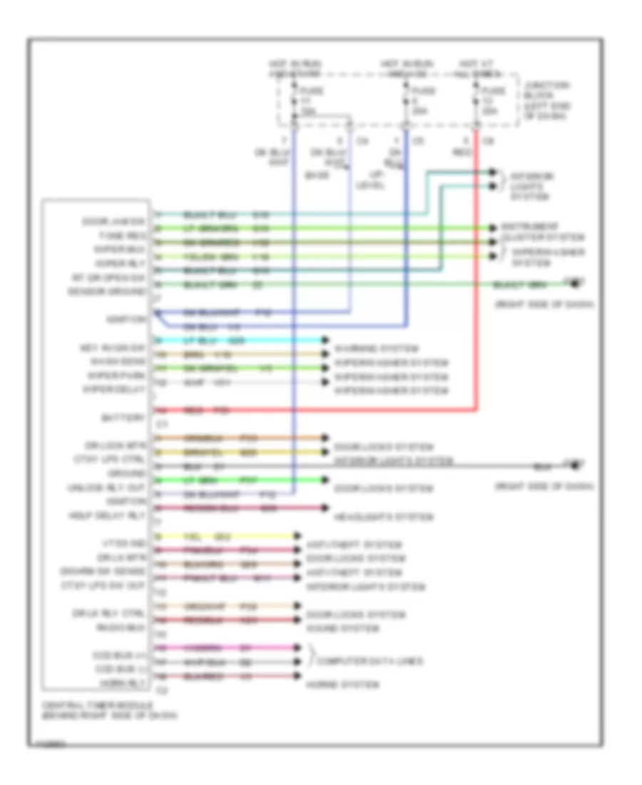
BODY COMPUTER Body Computer Wiring Diagrams for Dodge Dakota 1999 List of elements for Body Computer Wiring Diagrams for Dodge Dakota 1999: 67 (right side of dash) Anti-theft system Base Battery Ccd bus (+) Ccd bus (-) Central timer module (behind right side of dash) Computer data lines Ctsy lps ctrl Ctsy lps sw out Disarm sw sense Door jam sw Door locks system Dr lk mtr Dr lk rly ctrl Dr lock mtr F12 F35 Fuse 10a Fuse 20a G10 G16 G201 G26 G50 G52 G69 Ground Hdlp delay rly Headlights system Horn rly Horns system Hot at all times Hot in run and acc Hot in run and start Ignition Instrument cluster system Interior lights system Junction block (left end of dash) Key in ign sw M11 M20 P33 P34 P37 P38 Radio mux Red Rt dr open sw Sensor ground Sound system Tone req Unlock rly out Up- level V10 V18 V51 V52 Vtss ind Warning system Wash sens Wiper delay Wiper mux Wiper park Wiper rly Wiper/washer system X20
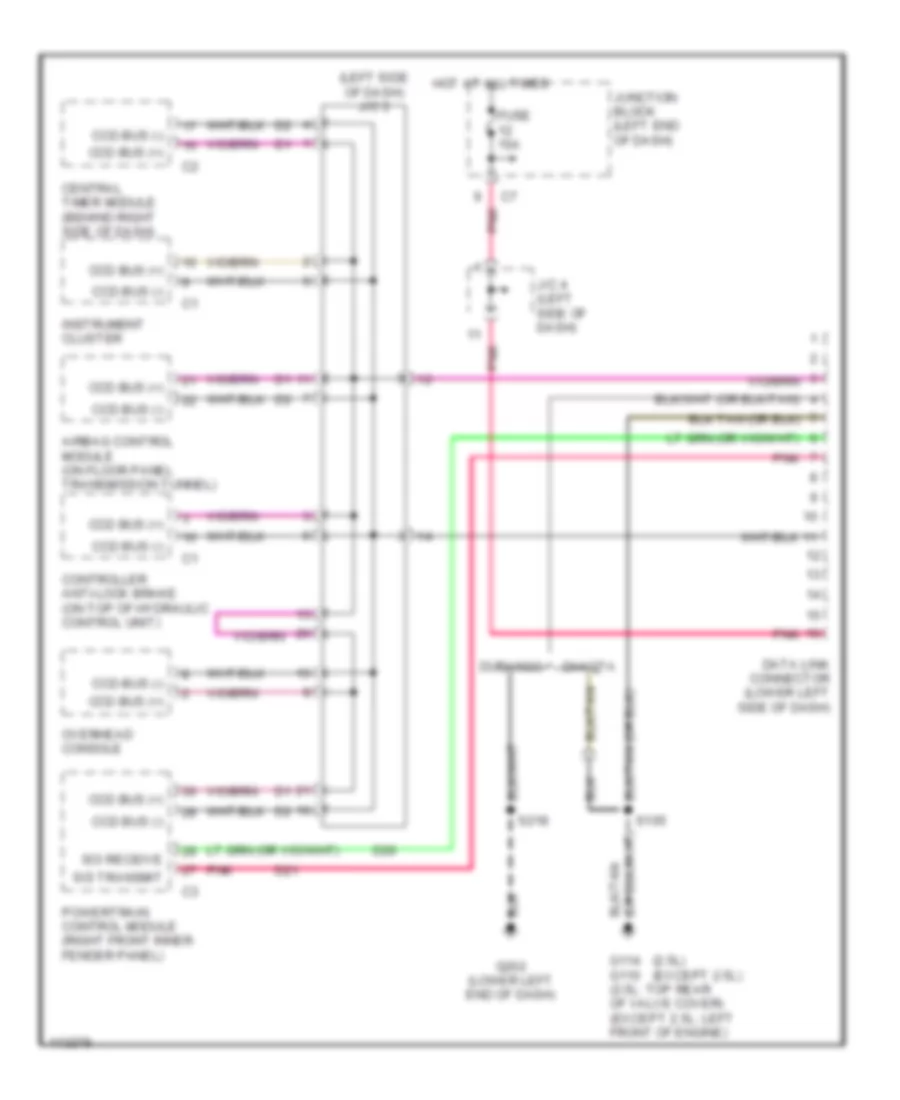
COMPUTER DATA LINES Computer Data Lines for Dodge Dakota 1999 List of elements for Computer Data Lines for Dodge Dakota 1999: 26 (2.5l) (except 2.5l) (left side of dash) j/c 3 Airbag control module (on floor panel transmission tunnel) Ccd bus (+) Ccd bus (-) Central timer module (behind right side of dash) Controller anti-lock brake (on top of hydraulic control unit) D20 D21 Dakota Data link connector (lower left side of dash) Durango Fuse 15a G114 g110 (2.5l: top rear of valve cover) (except 2.5l: left front of engine) G202 (lower left end of dash) Hot at all times Instrument cluster J/c 4 (left side of dash) Junction block (left end of dash) Overhead console Pnk Powertrain control module (right front inner fender panel) S105 S218 Sci receive Sci transmit
COOLING FAN
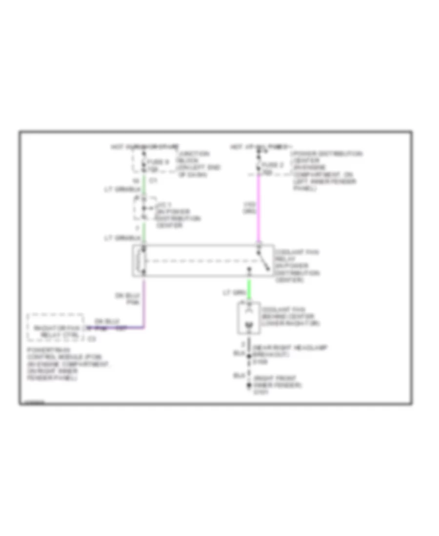
2.5L 2.5L, Cooling Fan Wiring Diagram for Dodge Dakota 1999 List of elements for 2.5L, Cooling Fan Wiring Diagram for Dodge Dakota 1999: 14 (near right headlamp breakout) s109 (right front inner fender) g101 C27 Coolant fan (behind center lower radiator) Coolant fan relay (in power distribution center) Fuse 2 30a Fuse 9 10a Hot at all times Hot in run or start J/c 1 (in power distribution center Junction block (on left end of dash) Power distribution center (in engine compartment, on left inner fender panel) Powertrain control module (pcm) (in engine compartment, on right inner fender panel) Radiator fan relay ctrl
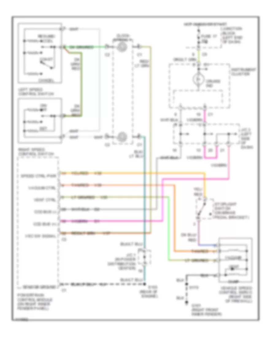
CRUISE CONTROL Cruise Control Wiring Diagram for Dodge Dakota 1999 List of elements for Cruise Control Wiring Diagram for Dodge Dakota 1999: 38 Cancel Ccd bus (+) Ccd bus (-) Clock- Coast Cruise ind Dump Fuse 17 10a G101 (right front inner fender) Hot in run or start Instrument cluster J/c 1 (in power distribution center) J/c 3 (left side of dash) Junction block (left end of dash) Left speed control switch On/ off Powertrain control module (on right inner fender panel) Red Resume/ accel Right speed control switch S103 (rear of engine) S170 Sensor ground Set Speed ctrl pwr Spring 1 Stoplight switch (on brake pedal bracket) Tan/red V32 V35 V36 V37 Vacuum Vacuum ctrl Vehicle speed control servo (right side of firewall) Vent Vent ctrl Vsc sw signal
ENGINE PERFORMANCE
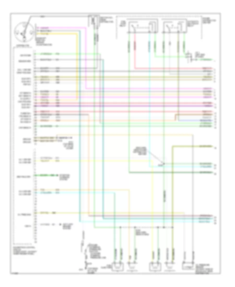
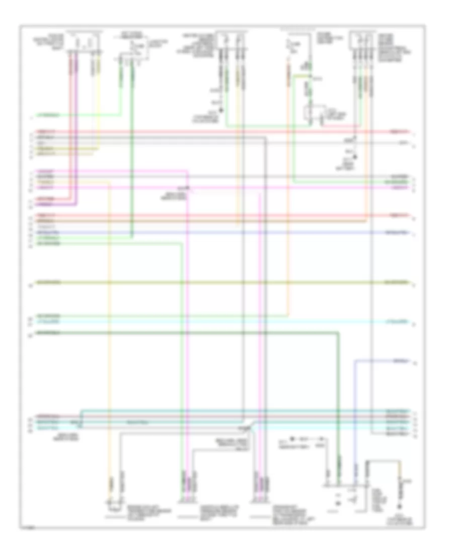
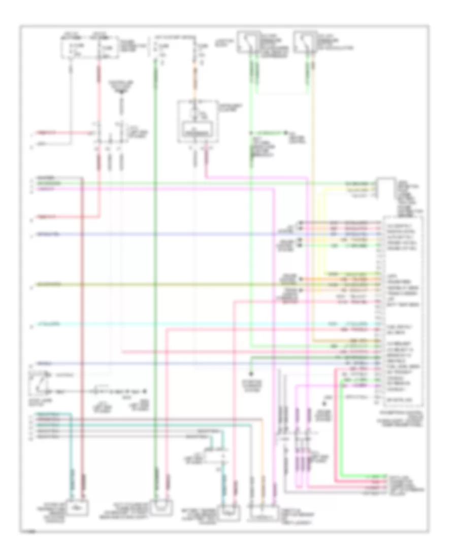
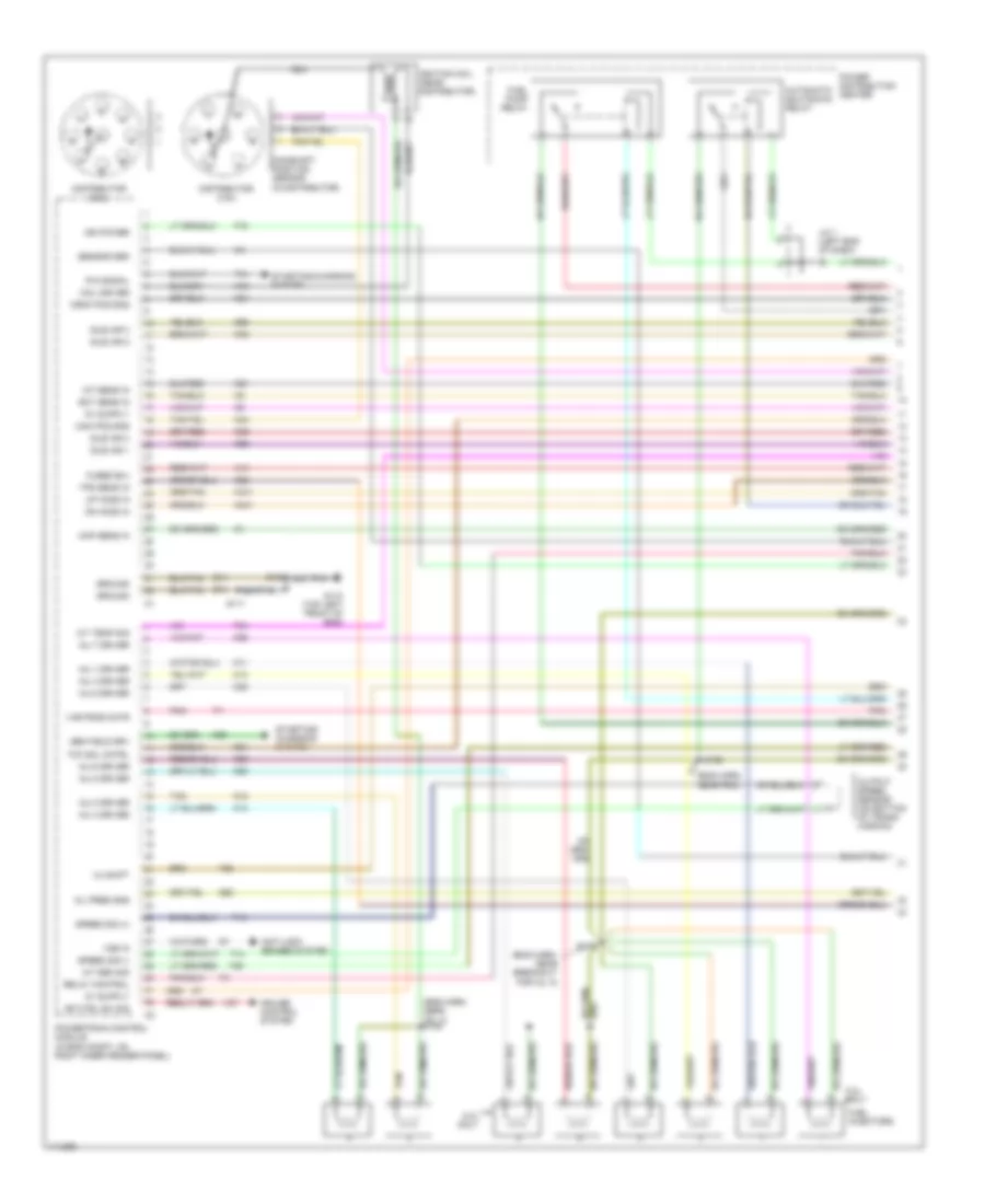
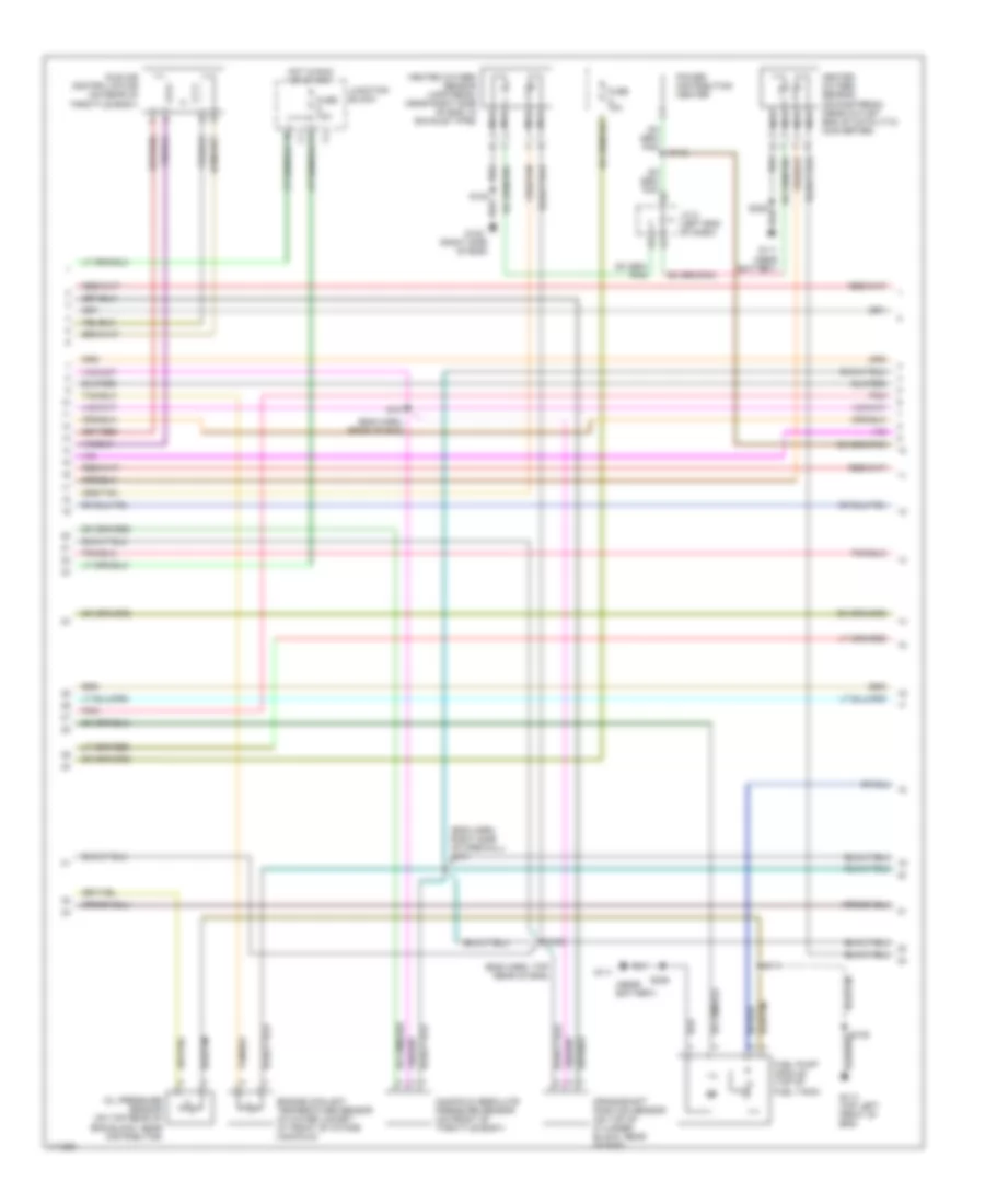
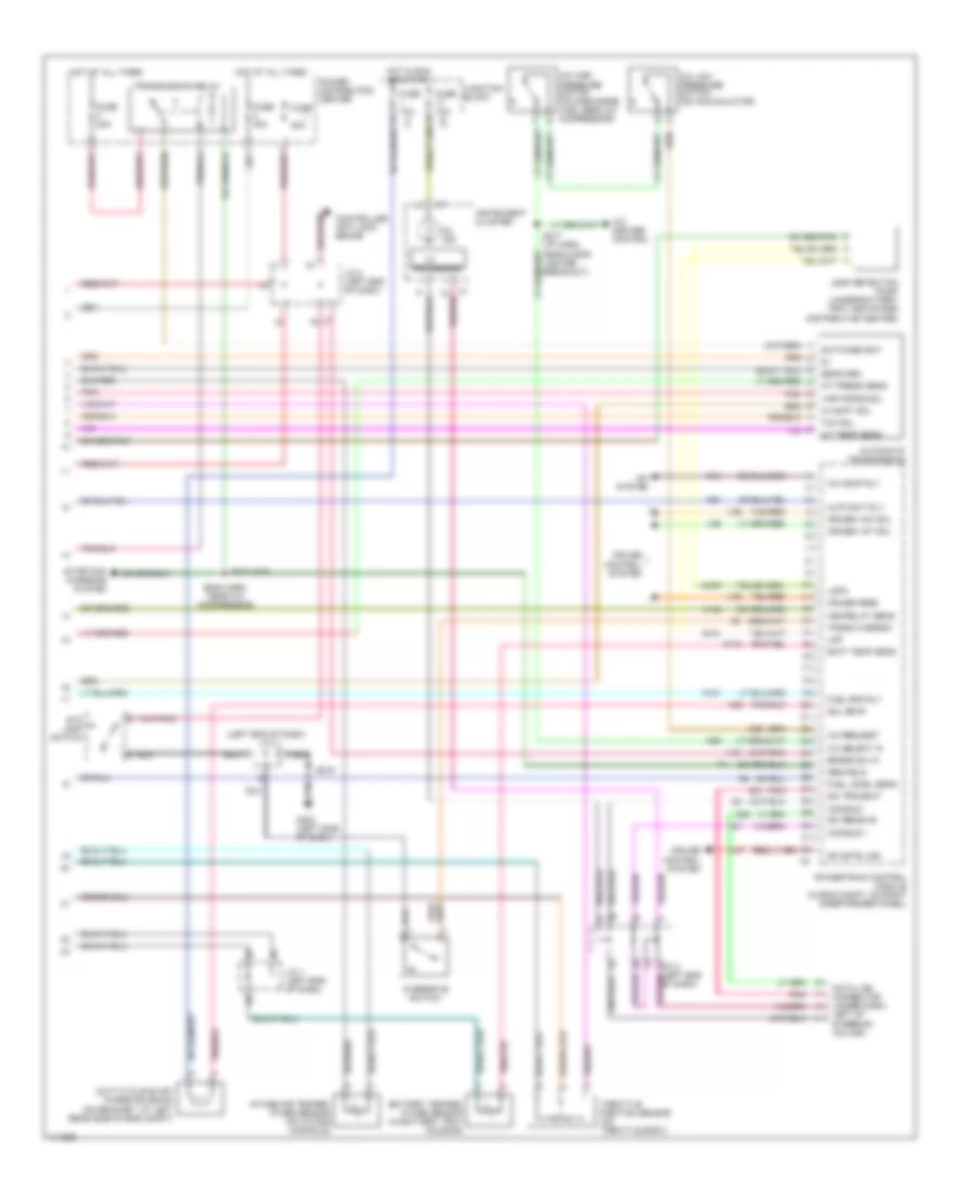
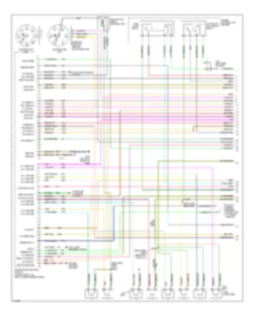
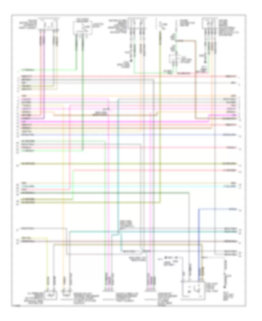
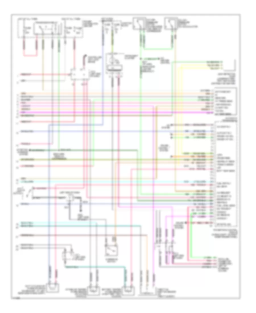
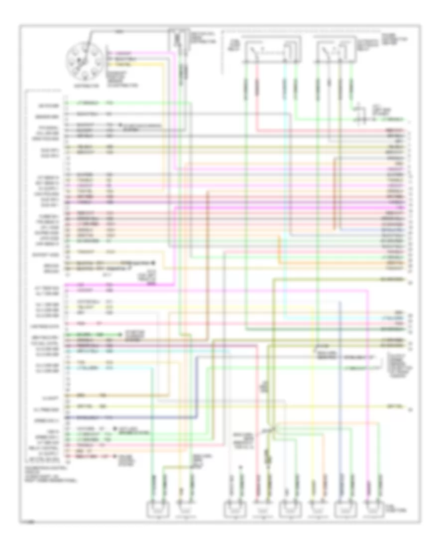
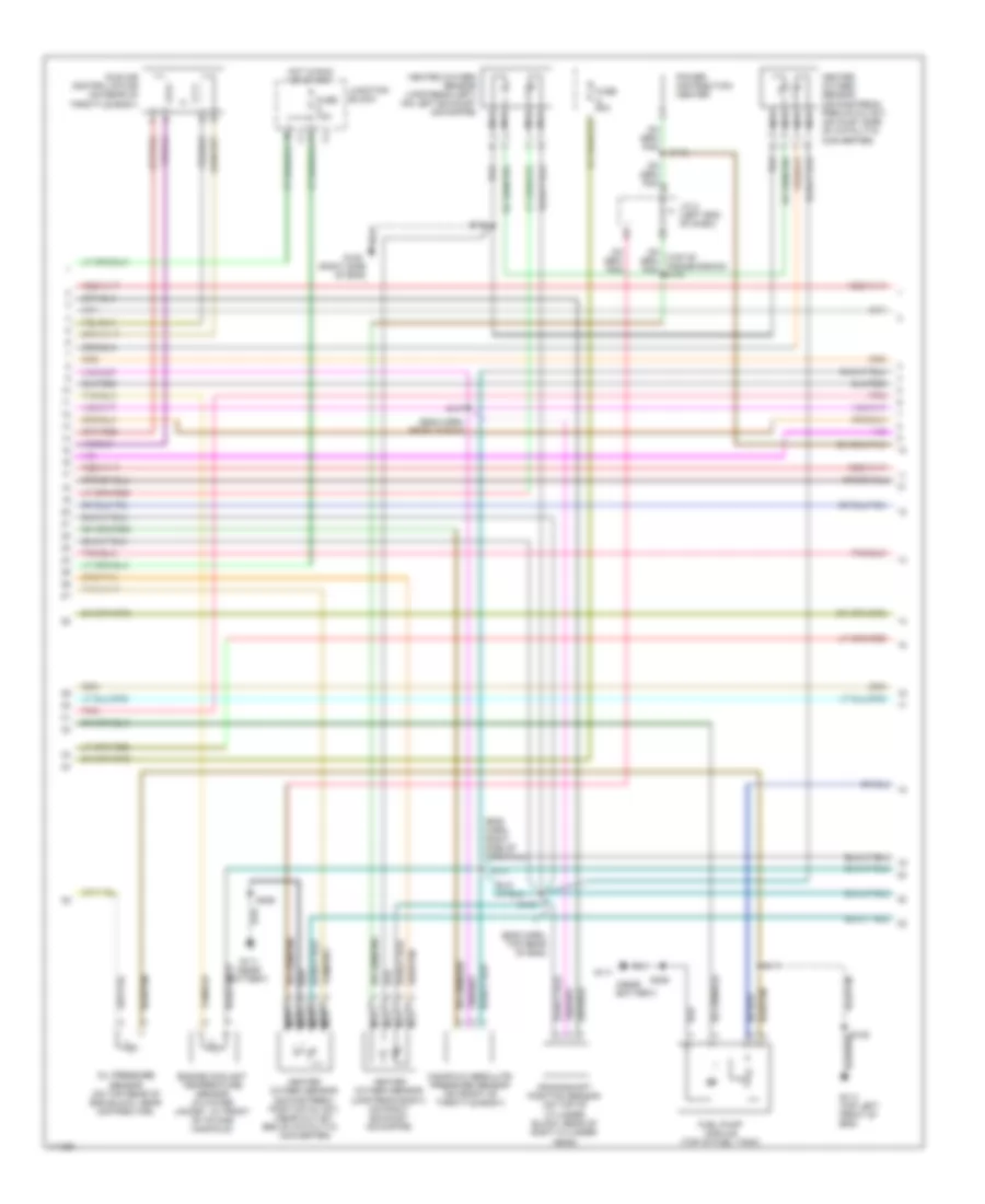
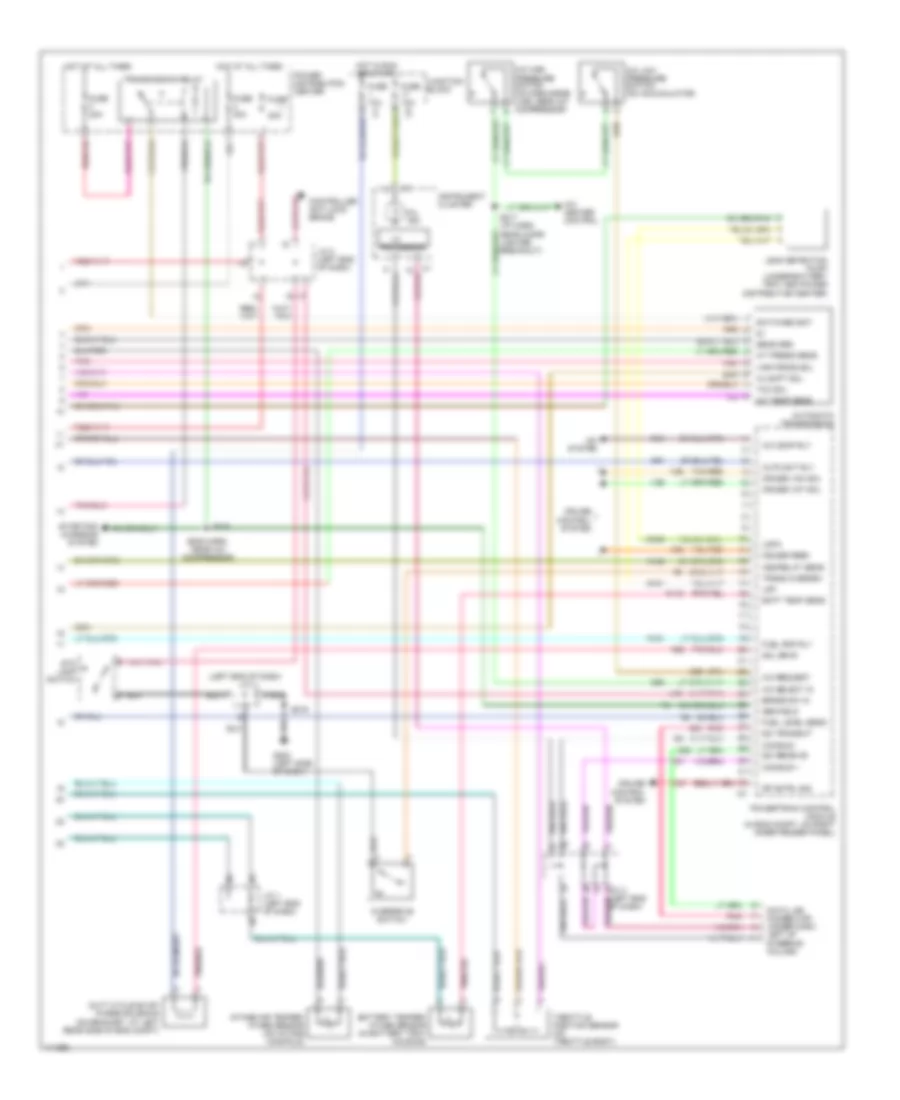
2.5L 2.5L, Engine Performance Wiring Diagrams (1 of 3) for Dodge Dakota 1999 List of elements for 2.5L, Engine Performance Wiring Diagrams (1 of 3) for Dodge Dakota 1999: 69 (eng harn, near power distribution center) (in distributor) (top rear of valve cover) A14 Anti-lock brakes system Automatic shutdown relay Cam pos sns Camshaft position sensor Coil 1 driver Crnk pos sns Distributor Dn ho2s in Ect sens in F18 Fuel injectors Fuel pump relay Fused b(+) G131 (top rear of valve cover) G60 Gen field drv Ground Iat sens in Idle air 1 Idle air 2 Idle air 3 Idle air 4 Ign power Ignition coil (near distributor) Inj 1 driver Inj 2 driver Inj 3 driver Inj 4 driver J/c 1 (left end of dash) K11 K12 K13 K14 K141 K19 K20 K21 K22 K24 K341 K39 K40 K44 K59 K60 K99 Map sens in Nca Oil pres sns Oil pressure sensor (on right side of eng block, near distributor) Power distribution center Power steering pressure switch (in power steering pressure line) Powertrain control module (in eng compt, on right inner fender panel) Psp sw S105 S106 (eng harn, rear of eng) S108 S158 Sensor grd Starting/ charging system Tan Tps sens in Up ho2s in Vss in Z12 2.5L, Engine Performance Wiring Diagrams (2 of 3) for Dodge Dakota 1999 List of elements for 2.5L, Engine Performance Wiring Diagrams (2 of 3) for Dodge Dakota 1999: 30 (eng harn, near breakout for inj. 3) (eng harn, rear of eng) (near (near battery) (top rear of valve cover) Battery) Crankshaft position sensor (in transmission bellhousing, at left rear side of eng) Engine coolant temperature sensor (on thermostat housing) Fuel pump module (top of fuel tank) Fuse 10a Fuse a 20a G111 G131 G131 (top rear of valve cover) Heated oxygen sensor (downstream) (near oulet end of catalyic converter) Heated oxygen sensor (upstream) (near left side of eng, in exhaust downpipe) Hot in run and start Idle air control motor (on throttle body) J/c 2 (left eng of dash) Junction block Manifold absolute pressure sensor (on side throttle body) Nca Power distribution center S101 S103 S105 S107 S108 S112 S306 2.5L, Engine Performance Wiring Diagrams (3 of 3) for Dodge Dakota 1999 List of elements for 2.5L, Engine Performance Wiring Diagrams (3 of 3) for Dodge Dakota 1999: 78 10a A/c comp rly A/c heater control A/c high pressure switch on discharge line, near a/c compressor) A/c low pressure switch (on accumulator) A/c request A/c select in A/c system A142 Asd relay sens Auto sht rly Batt temp sens Battery temper- ature sensor (in battery tray housing) Brake sw in C13 C20 C27 C32 C90 Ccd bus + Ccd bus - Controller anti-lock brake Cruise control system Cruise feed Cruise vac sol Cruise vnt sol D20 D21 Data link connector (under dash, left of steering column) Duty cycle/evap purge solenoid (on bracket, at right rear side of eng compt) Fuel level sens Fuel pmp rly Fuse Fuse 20a Fuse 30a G100 G101 G202 (left side of dash) G216 Gen field Hot at all times Hot in start or run I/o Instrument cluster Intake air temperature sensor (on intake manifold) J/c 1 (left end of dash) J/c 2 (left end of dash) J/c 3 (left end of dash) J/c 4 (left end of dash) Junction block K118 K151 K51 K52 Ldp Ldpa Leak detection pump (under battery tray and power distribution center) Mil ind. Pnk Power distribution center Powertrain control module (in eng compt, on right inner fender panel) Processor Rad fan cntrl S217 (i/p harn, near cigar lighter breakout) Sci receive Sci transmit Sol drvr Sp cntrl sig Starting/ charging system Stop lamps switch Tan/red Throttle position sensor (on throtlle body) Trans overdrv Trans- mission overdrive switch V32 V35 V36 V40
3.9L 3.9L, Engine Performance Wiring Diagrams (1 of 3) for Dodge Dakota 1999 List of elements for 3.9L, Engine Performance Wiring Diagrams (1 of 3) for Dodge Dakota 1999: 98 (eng harn, near breakout for inj. 5) (eng harn, near inj. 4) s106 (eng harn, near pdc) (in distributor) 3-4 shift 5.2l only A/t sen sig A/t temp sig A14 Anti-lock brakes system Automatic shutdown relay Cam pos sns Camshaft position sensor Coil driver Crnk pos sns Cruise control system Distributor (3.9l) Distributor (5.2l) Dn ho2s in Ect sens in F18 Fuel injectors Fuel pump relay Fused b(+) G110 (top left front of eng) G60 Gen field drv Ground Iat sens in Idle air 1 Idle air 2 Idle air 3 Idle air 4 Ign power Ignition coil (near distributor) Inj 1 driver Inj 2 driver Inj 3 driver Inj 4 driver Inj 5 driver Inj 6 driver Inj 7 driver Inj 8 driver J/c 1 (left end of dash) K11 K12 K13 K14 K19 K20 K21 K22 K24 K26 K28 K341 K38 K39 K40 K44 K441 K54 K58 K59 K60 Map sens in Nca Oil pres sns Output speed sensor (on bottom of trans- mission) P/n signal Pnk Power distribution center Powertrain control module (in eng compt, on right inner fender panel) Relay control S105 S110 S111 S158 Sensor grd Sp ctrl sw sig Speed sig (+) Speed sig (-) Starting/ charging system Starting/charging system T13 T14 T25 T34 T41 T60 Tan Tcc sol cntrl Tps sens in Up ho2s in V37 Var frce cntr Vss in Z14 3.9L, Engine Performance Wiring Diagrams (2 of 3) for Dodge Dakota 1999 List of elements for 3.9L, Engine Performance Wiring Diagrams (2 of 3) for Dodge Dakota 1999: 32 (eng harn, rear of eng) (eng harn, right side of firewall) s101 (eng harn, top rear of eng) (near battery) (right side of eng) Crankshaft position sensor (on top of cylinder block, rear of eng) Engine coolant temperature sensor (in water jacket, at front of intake manifold) Fuel pump module (top of fuel tank) Fuse 10a Fuse a 10a G110 (top left front of eng) G111 G111 (near battery) G120 Heated oxygen sensor (downstream) (near outlet end of catalytic converter) Heated oxygen sensor (upstream) (near right side of eng, in exhaust pipe) Hot in run or start Idle air control motor (on rear of throttle body) J/c 2 (left end of dash) Junction block Manifold absolute pressure sensor (on front of throttle body) Nca Oil pressure sensor (on top rear of eng block, near distributor) Pnk Power distribution center S103 S105 S107 S108 S111 S112 S306 3.9L, Engine Performance Wiring Diagrams (3 of 3) for Dodge Dakota 1999 List of elements for 3.9L, Engine Performance Wiring Diagrams (3 of 3) for Dodge Dakota 1999: 90 (a/t) s104 (eng harn, near a/c compressor) (left end of dash) 20a 3-4 shft sol A/c comp rly A/c heater control A/c high pressure switch (on discharge line, near a/c compressor) A/c low pressure switch (on accumulator) A/c request A/c select in A/c system A/t press sens A/t temp sens A142 Asd relay sens Auto sht rly Automatic transmission Batt temp sens Battery temper- ature sensor (in battery tray housing) Brake sw in C13 C20 C90 Ccd bus + Ccd bus - Controller anti-lock brake Cruise control system Cruise feed Cruise vac sol Cruise vnt sol D20 D21 Data link connector (under dash, left of steering column) Duty cycle evap/ purge solenoid (on bracket, at left rear side of eng compt) Fuel level sens Fuel pmp rly Fuse Fuse 10a Fuse 30a Fuse f 20a G100 G101 G202 (left side of dash) Gen field Hot at all times Hot in run or start I/o Instrument cluster Intake air temper- ature sensor (on intake manifold) J/c 1 (left end of dash) J/c 2 (left end of dash) J/c 3 (left end J/c 4 Junction block K118 K151 K51 K52 Ldp Ldpa Leak detection pump (under battery tray and power distribution center) Mil ind. Of dash) Overdrive switch Pnk Power distribution center Powertrain control module (in eng compt, on right inner fender panel) Processor S216 S217 (i/p harn, near cigar lighter breakout) Sci receive Sci transmit Sens grd Sol drvr Sp cntrl sig Starting/ charging system Sto lamp switch Switched bat Tan/red Tcc sol Throttle position sensor (on throttle body) Trans overdrv Transmission relay V32 V35 V36 V37 V40 Var force sol
5.2L 5.2L, Engine Performance Wiring Diagrams (1 of 3) for Dodge Dakota 1999 List of elements for 5.2L, Engine Performance Wiring Diagrams (1 of 3) for Dodge Dakota 1999: 98 (eng harn, near breakout for inj. 5) (eng harn, near inj. 4) s106 (eng harn, near pdc) (in distributor) 3-4 shift 5.2l only A/t sen sig A/t temp sig A14 Anti-lock brakes system Automatic shutdown relay Cam pos sns Camshaft position sensor Coil driver Crnk pos sns Cruise control system Distributor (3.9l) Distributor (5.2l) Dn ho2s in Ect sens in F18 Fuel injectors Fuel pump relay Fused b(+) G110 (top left front of eng) G60 Gen field drv Ground Iat sens in Idle air 1 Idle air 2 Idle air 3 Idle air 4 Ign power Ignition coil (near distributor) Inj 1 driver Inj 2 driver Inj 3 driver Inj 4 driver Inj 5 driver Inj 6 driver Inj 7 driver Inj 8 driver J/c 1 (left end of dash) K11 K12 K13 K14 K19 K20 K21 K22 K24 K26 K28 K341 K38 K39 K40 K44 K441 K54 K58 K59 K60 Map sens in Nca Oil pres sns Output speed sensor (on bottom of trans- mission) P/n signal Pnk Power distribution center Powertrain control module (in eng compt, on right inner fender panel) Relay control S105 S110 S111 S158 Sensor grd Sp ctrl sw sig Speed sig (+) Speed sig (-) Starting/ charging system Starting/charging system T13 T14 T25 T34 T41 T60 Tan Tcc sol cntrl Tps sens in Up ho2s in V37 Var frce cntr Vss in Z14 5.2L, Engine Performance Wiring Diagrams (2 of 3) for Dodge Dakota 1999 List of elements for 5.2L, Engine Performance Wiring Diagrams (2 of 3) for Dodge Dakota 1999: 32 (eng harn, rear of eng) (eng harn, right side of firewall) s101 (eng harn, top rear of eng) (near battery) (right side of eng) Crankshaft position sensor (on top of cylinder block, rear of eng) Engine coolant temperature sensor (in water jacket, at front of intake manifold) Fuel pump module (top of fuel tank) Fuse 10a Fuse a 10a G110 (top left front of eng) G111 G111 (near battery) G120 Heated oxygen sensor (downstream) (near outlet end of catalytic converter) Heated oxygen sensor (upstream) (near right side of eng, in exhaust pipe) Hot in run or start Idle air control motor (on rear of throttle body) J/c 2 (left end of dash) Junction block Manifold absolute pressure sensor (on front of throttle body) Nca Oil pressure sensor (on top rear of eng block, near distributor) Pnk Power distribution center S103 S105 S107 S108 S111 S112 S306 5.2L, Engine Performance Wiring Diagrams (3 of 3) for Dodge Dakota 1999 List of elements for 5.2L, Engine Performance Wiring Diagrams (3 of 3) for Dodge Dakota 1999: 90 (a/t) s104 (eng harn, near a/c compressor) (left end of dash) 20a 3-4 shft sol A/c comp rly A/c heater control A/c high pressure switch (on discharge line, near a/c compressor) A/c low pressure switch (on accumulator) A/c request A/c select in A/c system A/t press sens A/t temp sens A142 Asd relay sens Auto sht rly Automatic transmission Batt temp sens Battery temper- ature sensor (in battery tray housing) Brake sw in C13 C20 C90 Ccd bus + Ccd bus - Controller anti-lock brake Cruise control system Cruise feed Cruise vac sol Cruise vnt sol D20 D21 Data link connector (under dash, left of steering column) Duty cycle evap/ purge solenoid (on bracket, at left rear side of eng compt) Fuel level sens Fuel pmp rly Fuse Fuse 10a Fuse 30a Fuse f 20a G100 G101 G202 (left side of dash) Gen field Hot at all times Hot in run or start I/o Instrument cluster Intake air temper- ature sensor (on intake manifold) J/c 1 (left end of dash) J/c 2 (left end of dash) J/c 3 (left end J/c 4 Junction block K118 K151 K51 K52 Ldp Ldpa Leak detection pump (under battery tray and power distribution center) Mil ind. Of dash) Overdrive switch Pnk Power distribution center Powertrain control module (in eng compt, on right inner fender panel) Processor S216 S217 (i/p harn, near cigar lighter breakout) Sci receive Sci transmit Sens grd Sol drvr Sp cntrl sig Starting/ charging system Sto lamp switch Switched bat Tan/red Tcc sol Throttle position sensor (on throttle body) Trans overdrv Transmission relay V32 V35 V36 V37 V40 Var force sol
5.9L 5.9L, Engine Performance Wiring Diagrams (1 of 3) for Dodge Dakota 1999 List of elements for 5.9L, Engine Performance Wiring Diagrams (1 of 3) for Dodge Dakota 1999: 100 (eng harn, near breakout for inj. 5) (eng harn, near inj. 4) s106 (eng harn, near pdc) (in distributor) 3-4 shift A/t sen sig A/t temp sig A14 Anti-lock brakes system Automatic shutdown relay Cam pos sns Camshaft position sensor Coil driver Crnk pos sns Cruise control system Distributor Dn-post ho2s Dn-pre ho2s Ect sens in F18 Fuel injectors Fuel pump relay Fused b(+) G110 (top left front of eng) G60 Gen field drv Ground Iat sens in Idle air 1 Idle air 2 Idle air 3 Idle air 4 Ign power Ignition coil (near distributor) Inj 1 driver Inj 2 driver Inj 3 driver Inj 4 driver Inj 5 driver Inj 6 driver Inj 7 driver Inj 8 driver J/c 1 (left end of dash) K11 K12 K13 K14 K141 K19 K20 K21 K22 K24 K241 K26 K28 K341 K38 K39 K40 K44 K441 K54 K58 K59 K60 Map sens in Nca Oil pres sns Output speed sensor (on bottom of trans- mission) P/n signal Pnk Power distribution center Powertrain control module (in eng compt, on right inner fender panel) Relay control S105 S110 S111 S158 Sensor grd Sp ctrl sw sig Speed sig (+) Speed sig (-) Starting/ charging system Starting/charging system T13 T14 T25 T34 T41 T60 Tan Tcc sol cntrl Tps sens in Up-l ho2s Up-r ho2s V37 Var frce cntr Vss in Z14 5.9L, Engine Performance Wiring Diagrams (2 of 3) for Dodge Dakota 1999 List of elements for 5.9L, Engine Performance Wiring Diagrams (2 of 3) for Dodge Dakota 1999: 38 (eng harn, rear of eng) (eng harn, right side of firewall) (eng harn, top rear of eng) (near battery) (right side of eng) Converter) Crankshaft position sensor (on top of cylinder block, rear of right cylinder End of catalytic Engine coolant temperature sensor (in water jacket, at front of intake manifold) Fuel pump module (top of fuel tank) Fuse 10a Fuse a 20a G110 (top left front of eng) G111 G111 (near battery) G120 Head) Heated oxygen sensor (downstream pre-catalyst) (on inlet side of catalytic converter) Heated oxygen sensor (downstream- post-catalyst) (near outlet Heated oxygen sensor (upstream-left) (on left exhaust downpipe) Heated oxygen sensor (upstream-right) (on right exhaust downpipe) Hot in run or start Idle air control motor (on rear of throttle body) J/c 2 (left end of dash) Junction block Manifold absolute pressure sensor (on front of throttle body) Nca Oil pressure sensor (on top rear of eng block, near distributor) Pnk Power distribution center S101 S103 S105 S107 S108 S111 S112 S306 5.9L, Engine Performance Wiring Diagrams (3 of 3) for Dodge Dakota 1999 List of elements for 5.9L, Engine Performance Wiring Diagrams (3 of 3) for Dodge Dakota 1999: 90 (eng harn, near a/c compressor) (left end of dash) 20a 3-4 shft sol A/c comp rly A/c heater control A/c high pressure switch (on discharge line, near a/c compressor) A/c low pressure switch (on accumulator) A/c request A/c select in A/c system A/t press sens A/t temp sens A142 Asd relay sens Auto sht rly Automatic transmission Batt temp sens Battery temper- ature sensor (in battery tray housing) Brake sw in C13 C20 C90 Ccd bus + Ccd bus - Controller anti-lock brake Cruise control system Cruise feed Cruise vac sol Cruise vnt sol D20 D21 Data link connector (under dash, left of steering column) Duty cycle evap/ purge solenoid (on bracket, at left rear side of eng compt) Fuel level sens Fuel pmp rly Fuse Fuse 10a Fuse 30a Fuse f 20a G100 G101 G202 (left side of dash) Gen field Hot at all times Hot in run or start I/o Instrument cluster Intake air temper- ature sensor (on intake manifold) J/c 1 (left end of dash) J/c 2 (left end of dash) J/c 3 (left end J/c 4 Junction block K118 K151 K51 K52 Ldp Ldpa Leak detection pump (under battery tray and power distribution center) Mil ind. Of dash) Overdrive switch Pnk Power distribution center Powertrain control module (in eng compt, on right inner fender panel) Processor S104 S216 S217 (i/p harn, near cigar lighter breakout) Sci receive Sci transmit Sens grd Sol drvr Sp cntrl sig Starting/ charging system Sto lamp switch Switched bat Tan/red Tcc sol Throttle position sensor (on throttle body) Trans overdrv Transmission relay V32 V35 V36 V37 V40 Var force sol
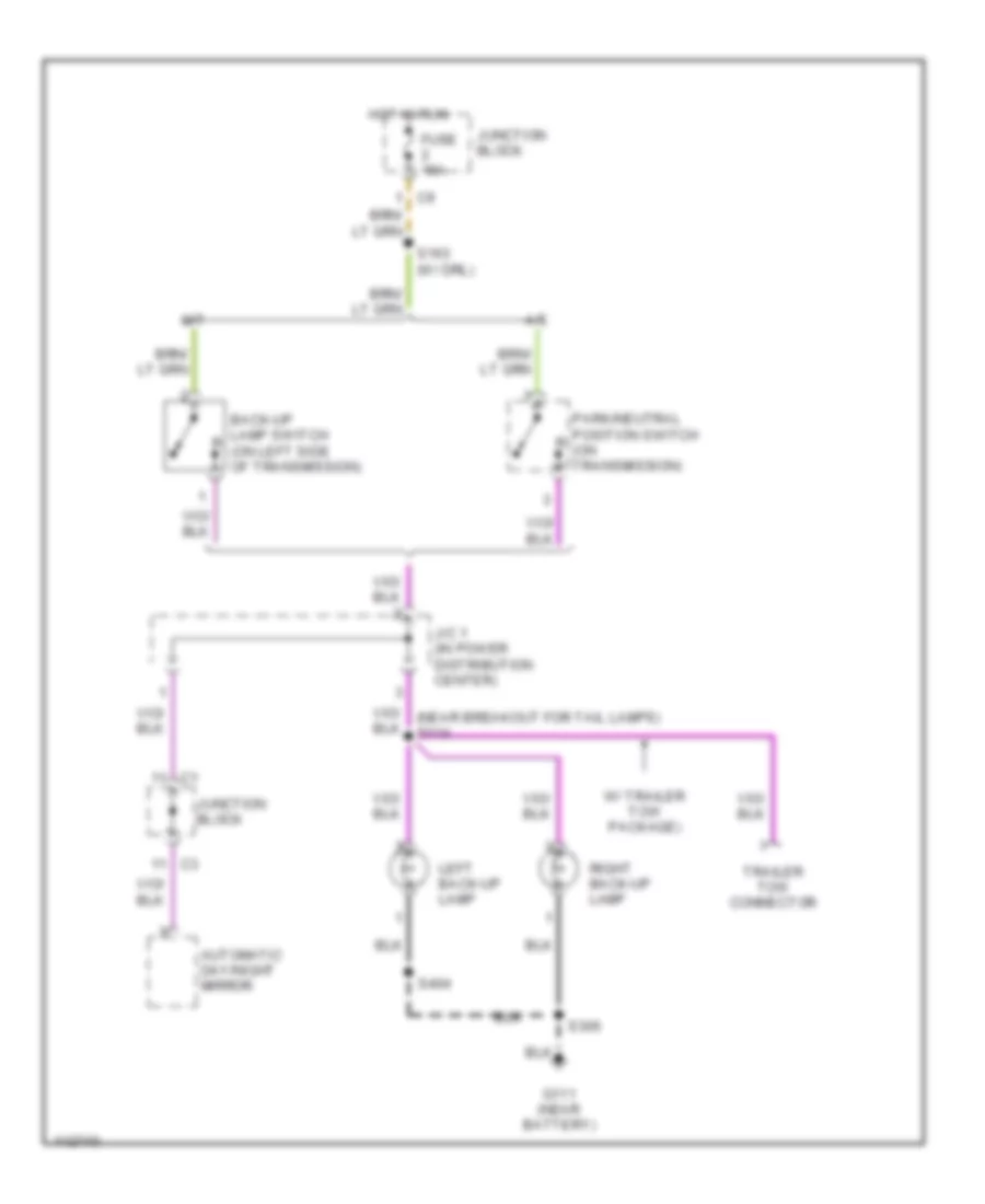
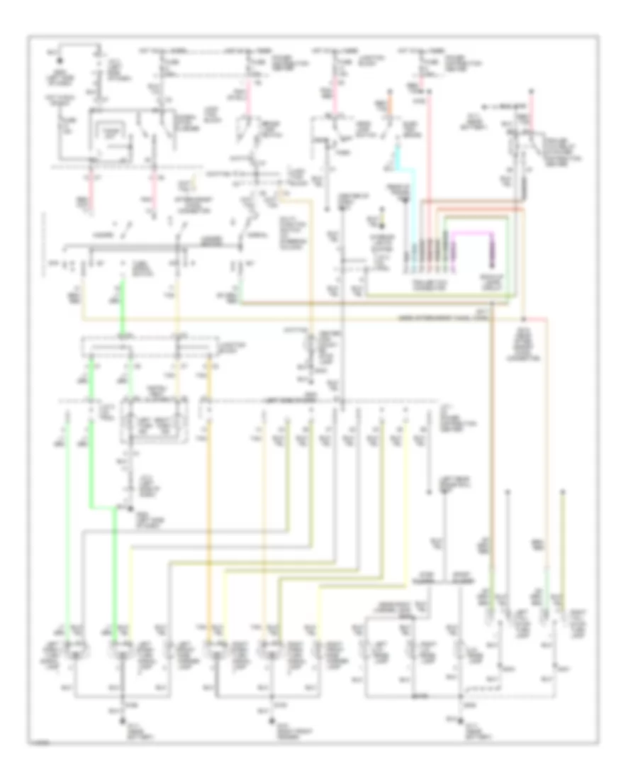
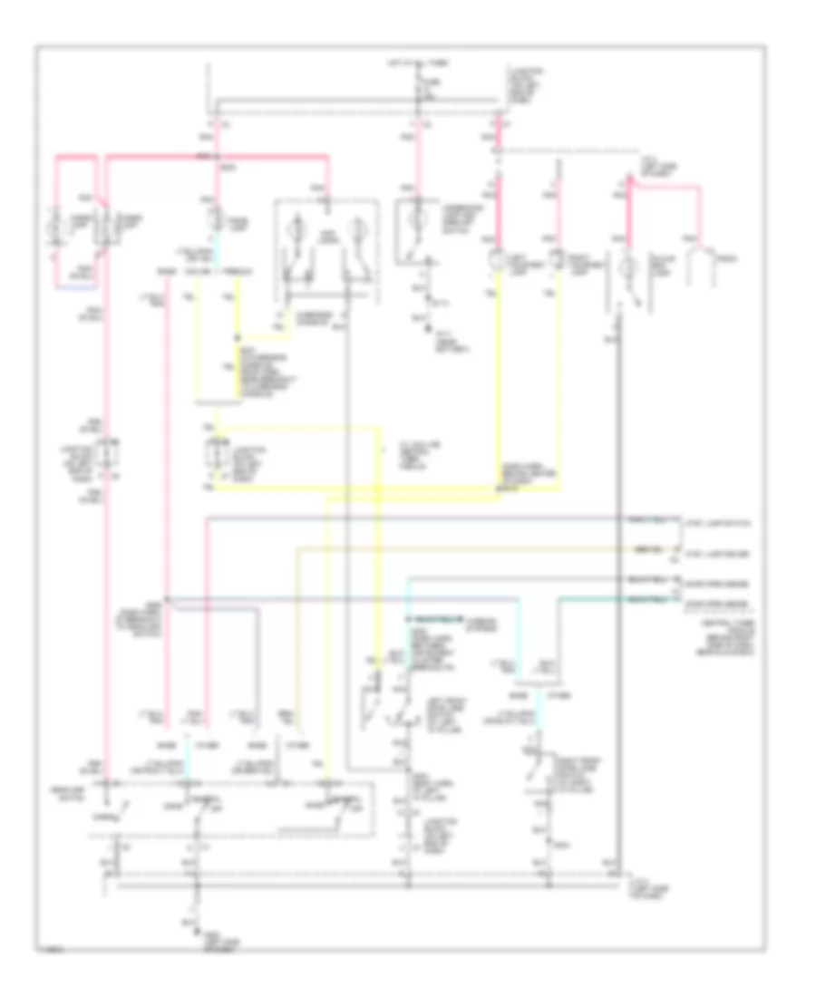
EXTERIOR LIGHTS Back-up Lamps Wiring Diagram for Dodge Dakota 1999 List of elements for Back-up Lamps Wiring Diagram for Dodge Dakota 1999: 17 A/t Automatic day/night mirror Back-up lamp switch (on left side of transmission) Fuse 15a G111 (near battery) Hot in run J/c 1 (in power distribution center) Junction block Left back-up lamp M/t Park/neutral position switch (on transmission) Right back-up lamp S163 (w/ drl) S306 S404 Trailer tow connector W/ trailer tow package) Exterior Lamps & Trailer connector Wiring Diagram for Dodge Dakota 1999 List of elements for Exterior Lamps & Trailer connector Wiring Diagram for Dodge Dakota 1999: 68 (center of dash) s213 (left rear frame rail) s316 (near right license lamp) s405 (rear of frame) g415 Aftermarket chmsl connector B2 c1 Back-up lamps circuit Brake lamp switch Center high mount- ed stop lamp Combin- ation flasher Elec- tric brake Fuse 15a Fuse 20a Fuse 40a Fuse d 25a G101 (right front fender) G111 (near battery) G202 (left side of dash) Hazard Hazard switch Head Head- lamp switch Hot at all times Hot in run or acc Instru- ment cluster Interior lights system J/c 1 (in power distribution center) J/c 2 (in pdc) J/c 4 (left side of dash) Junc- tion block Junction block Left front side marker lamp Left lic- ense lamp Left park/ turn signal lamp Left tail/ stop/ turn lamp Left turn ind Lic- ense lamp Multi- function switch (at steering column) Normal Off Park Pnk Pnk/ red Power distribution center Red/ tan Red/tan Right front side marker lamp Right lic- ense lamp Right park/ turn signal lamp Right tail/ stop/ turn lamp Right turn ind S109 S162 S166 S306 S317 (near aftermarket chmsl conn) S318 (near after- market chmsl connector) S401 S403 S404 S406 Sport bumper Step bumper Tan Timing ckt Trailer tow connector Trailer tow relay (in power distribution center) Turn signal switch
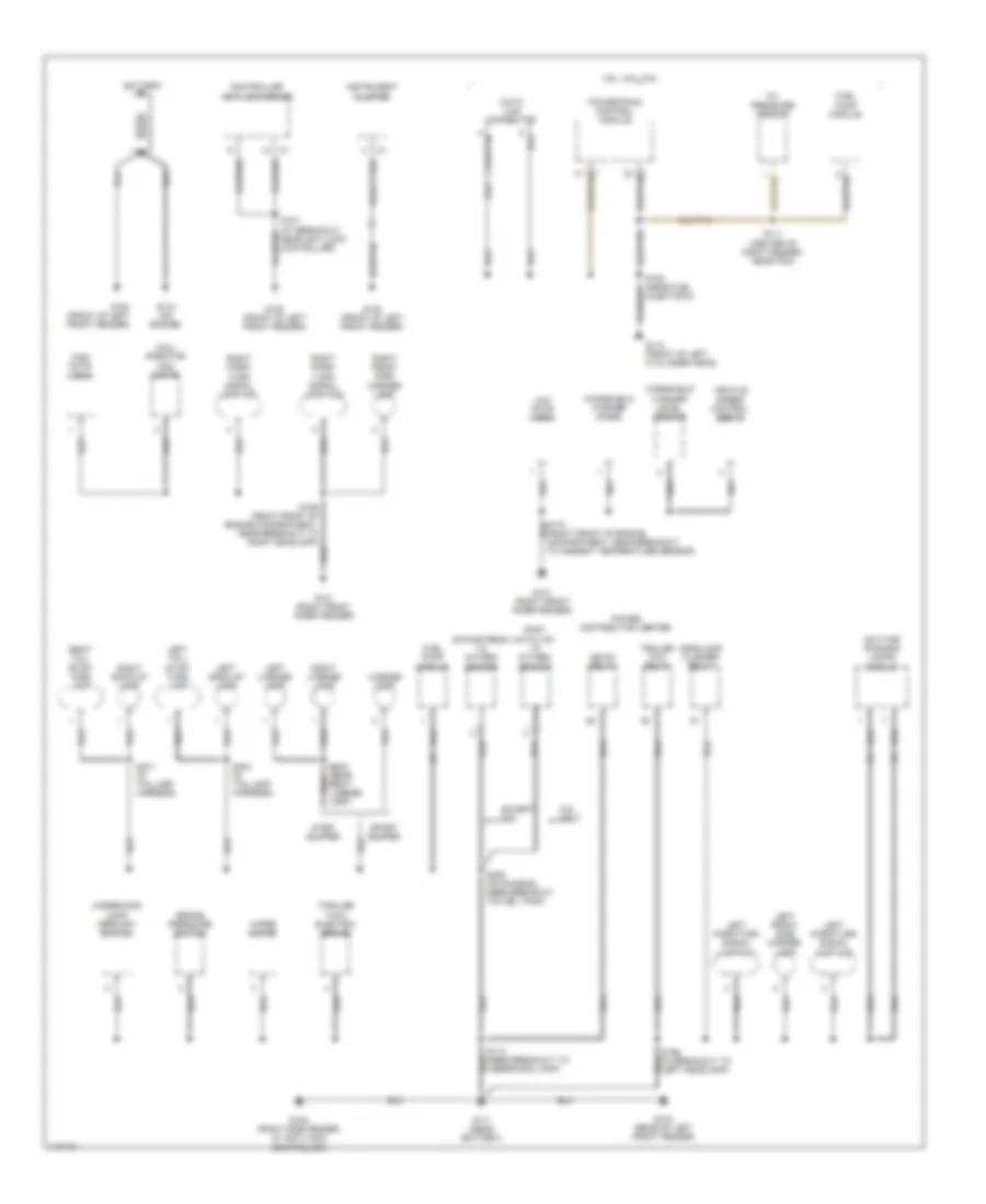
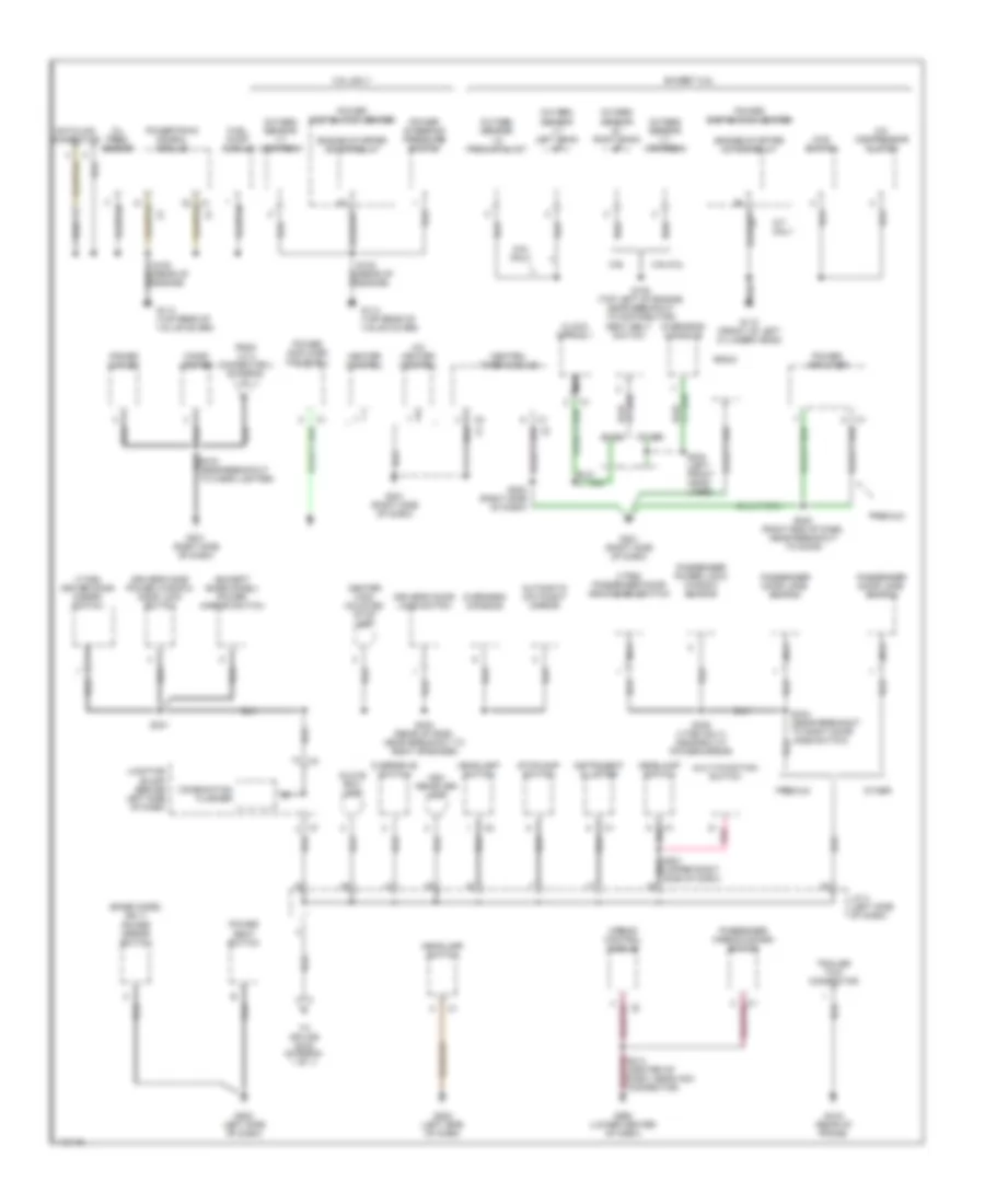
GROUND DISTRIBUTION Ground Distribution Wiring Diagram (1 of 2) for Dodge Dakota 1999 List of elements for Ground Distribution Wiring Diagram (1 of 2) for Dodge Dakota 1999: 56 (2.5l) radiator fan motor (trailer tow) electric brake 3.9l, 5.2l, 5.9l 31 c1 32 c1 5.9l only Battery Brake pressure switch Controller anti-lock brake Data link connector Daytime running lamps module Downstream 1/2 oxygen sensor Except 5.9l Fuel pump module G100 (front of left front fender) G101 (right front inner fender) G104 (rear of left front fender) G105 (right side fender, at anti-lock controller) G110 (front of left cyclinder head) G111 (near battery) G133 (on engine) Headlamp flasher relay Hevac relay High note horn Injector 5) Instrument cluster Left back-up lamp Left front side marker lamp Left license lamp Left park/turn signal lamp no1 Left park/turn signal lamp no2 Left tail/ stop/ turn lamp License lamp Low note horn Oil pressure sensor Post catalyst 1/3 oxygen sensor Power distribution center Powertrain control module Right back-up lamp Right front side marker lamp Right license lamp Right park/ turn signal lamp no1 Right park/ turn signal lamp no2 Right tail/ stop/ turn lamp S111 (center of right fender, near pcm) S306 (on chassis, near breakout to fuel tank) S401 (in taillamp harness) S404 (in taillamp harness) Sport bumper Step bumper Trailer tow relay Underhood lamp/ mercury switch Vehicle speed control servo Windshield washer level sensor Windshield washer pump Wiper motor Ground Distribution Wiring Diagram (2 of 2) for Dodge Dakota 1999 List of elements for Ground Distribution Wiring Diagram (2 of 2) for Dodge Dakota 1999: 74 (base model only) power mirror switch (except base model) power mirror switch (vtss) driver door disarm switch (vtss) passenger door arm/disarm switch 2.5l only 3.9l/5.2l 4wd switch 5.9l 5.9l only A/c compressor clutch A/c heater control Airbag control module Ash receiver lamp Automatic day/night mirror Base Center high mounted stop lamp Central timer module Cigar lighter Clock spring 1 Combination flasher Datalink connector Driver's door jamb switch Driver's side power window/ door lock switch Engine starter motor relay Except 2.5l From j/c 4 connector 4 (diagram 1 of 1) Fuel pump module G110 (front of left cylinder head) G114 (top rear of valve cover) G201 (right side of dash) G202 (left side of dash) G206 (lower center of dash) G415 (rear of frame) Glove box lamp Headlamp switch Heater control Instrument cluster J/c 4 (left side of dash) Junction block (behind left side of dash) M/t only Multi-function switch Nca Oil pres. sensor Other Overdrive switch Overhead console Oxygen sensor 1/1 left bank up Oxygen sensor 1/1 upstream Oxygen sensor 1/2 pre-catalyst Oxygen sensor 2/1 right bank up Passenger airbag disarm switch Passenger door jamb switch Passenger power lock/ window switch Pnk Power amplifier Power amplifier (midlevel) Power distibution center Power outlet Power seat switch Power steering pressure switch Powertrain conrol module Premium Radio S108 (top left of engine, near breakout to distributor) S223 (right side of dash) S234 (left front head- liner) S240 (right end of dash, near breakout to door) S301 S335 (vtss only) (near b/o at power mirror) S403 (rear of roof, near breakout to right speaker) Seat belt switch Stoplamp switch To splice s216 (diagram 1 of 1) Trailer tow connector
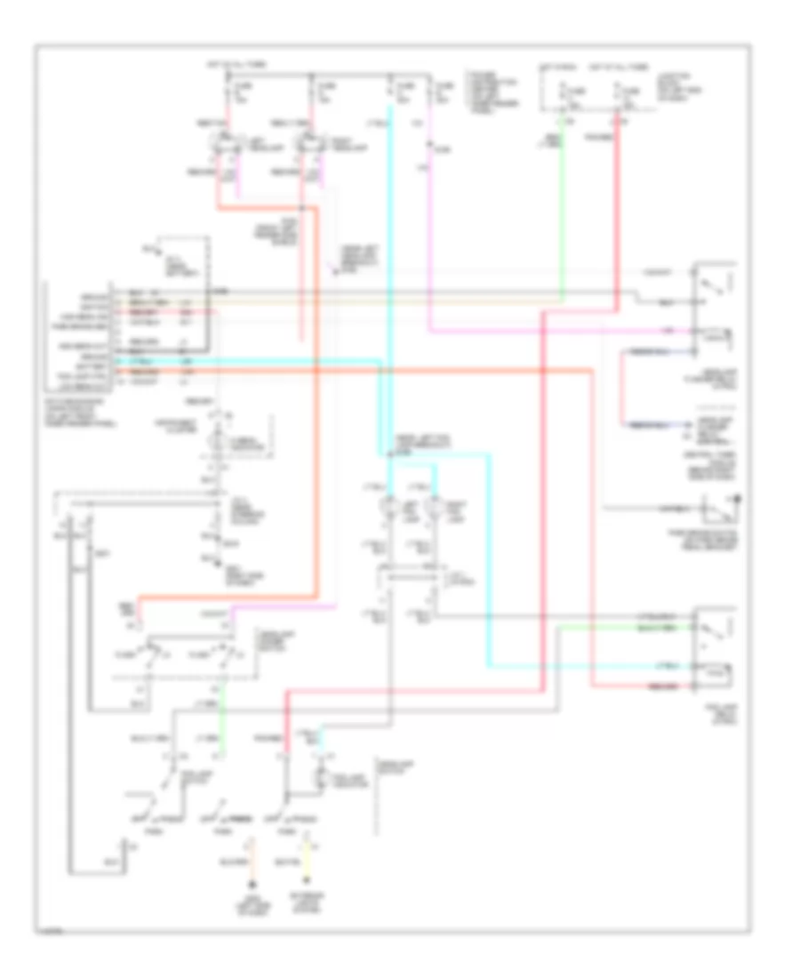
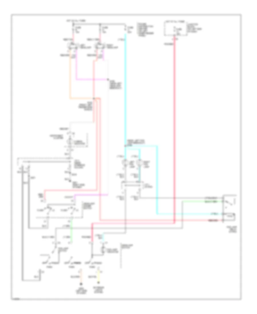
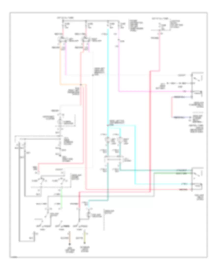
HEADLIGHTS Headlight Wiring Diagram, with DRL for Dodge Dakota 1999 List of elements for Headlight Wiring Diagram, with DRL for Dodge Dakota 1999: 58 (near left fog lamp breakout) s169 (near left headlamp breakout) s168 Battery Central timer module (behind right side of dash) Control Daytime running lamps module (on left front inner fender panel) Exterior lights system Flash Fog lamp ctrl Fog lamp indicator Fog lamp relay (in pdc) Fog lamp switch Fuse 15a Fuse b 15a Fuse c 20a Fuse e 20a Fuse g 15a G11 G111 (near battery) G201 (right side of dash) G202 (left side of dash) G34 Ground Head Headlamp dimmer switch Headlamp flasher relay (in pdc) Headlamp flasher relay c2 Headlamp switch Hi beam indicator High beam ind High beam out Hot at all times Hot in run Ignition Instrument cluster J/c 1 (in pdc) J/c 4 (near steering column) Junction block (on left end of dash) L10 L161 L39 Left fog lamp Left headlamp Low beam out Off Park Park brake sen Park brake switch (on park brake pedal bracket) Pnk/red Power distribution center (on left inner fender panel) Red/tan Right fog lamp Right headlamp S159 S164 (front left fender side shield) S166 S201 S216 Headlight Wiring Diagram, without DRL & with Track for Dodge Dakota 1999 List of elements for Headlight Wiring Diagram, without DRL & with Track for Dodge Dakota 1999: 34 (near left fog lamp breakout) s169 Exterior lights system Flash Fog lamp indicator Fog lamp relay (in pdc) Fog lamp switch Fuse 15a Fuse b 15a Fuse c 20a Fuse g 15a G201 (right side of dash) G202 (left side of dash) Head Headlamp dimmer switch Headlamp switch Hi beam indicator Hot at all times Instrument cluster J/c 1 (in pdc) J/c 4 (near steering column) Junction block (on left end of dash) Left fog lamp Left headlamp Off Park Pnk/red Power distribution center (on left inner fender panel) Red/tan Right fog lamp Right headlamp S164 (front left fender side shield) S168 (near left headlamp breakout) S201 S216 Headlight Wiring Diagram, without DRL & without Track for Dodge Dakota 1999 List of elements for Headlight Wiring Diagram, without DRL & without Track for Dodge Dakota 1999: 42 (near left fog lamp breakout) s169 (near left headlamp breakout) s168 Central timer module (behind right side of dash) Control Exterior lights system Flash Fog lamp indicator Fog lamp relay (in pdc) Fog lamp switch Fuse 15a Fuse b 15a Fuse c 20a Fuse e 20a Fuse g 15a G111 (near battery) G201 (right side of dash) G202 (left side of dash) Head Headlamp dimmer switch Headlamp flasher relay (in pdc) Headlamp flasher relay c2 Headlamp switch Hi beam indicator Hot at all times Instrument cluster J/c 1 (in pdc) J/c 4 (near steering column) Junction block (on left end of dash) Left fog lamp Left headlamp Off Park Pnk/red Power distribution center (on left inner fender panel) Red/tan Right fog lamp Right headlamp S159 S164 (front left fender side shield) S166 S201 S216
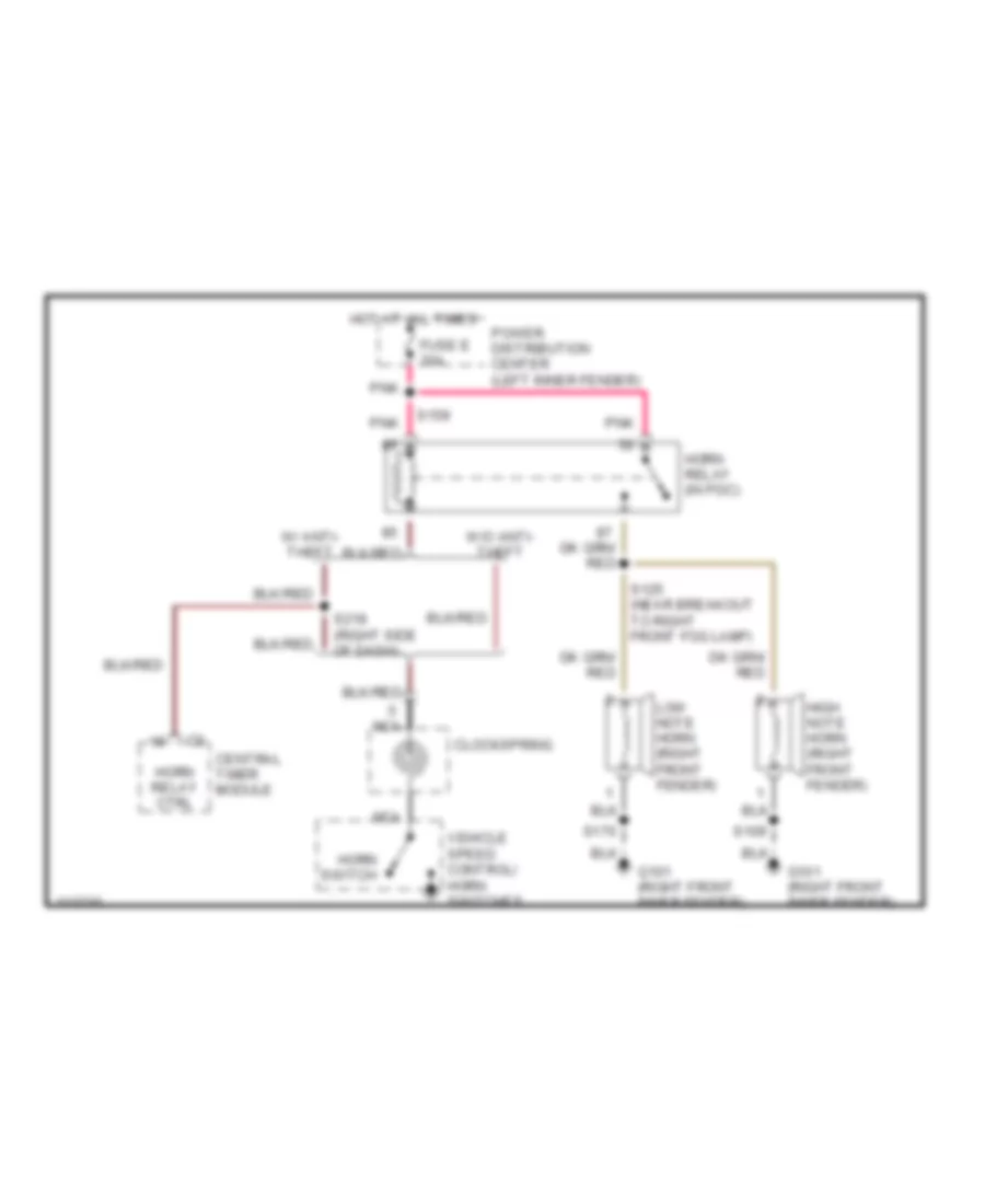
HORN Horn Wiring Diagram for Dodge Dakota 1999 List of elements for Horn Wiring Diagram for Dodge Dakota 1999: 21 Central timer module Clockspring Fuse e 20a G101 (right front inner fender) High note horn (right front fender) Horn relay (in pdc) Horn relay ctrl Horn switch Hot at all times Low note horn (right front fender) Nca Pnk Power distribution center (left inner fender) S109 S125 (near breakout to right front fog lamp) S159 S170 S218 (right side of dash) Vehicle speed control/ horn switches W/ anti- theft W/o anti- theft
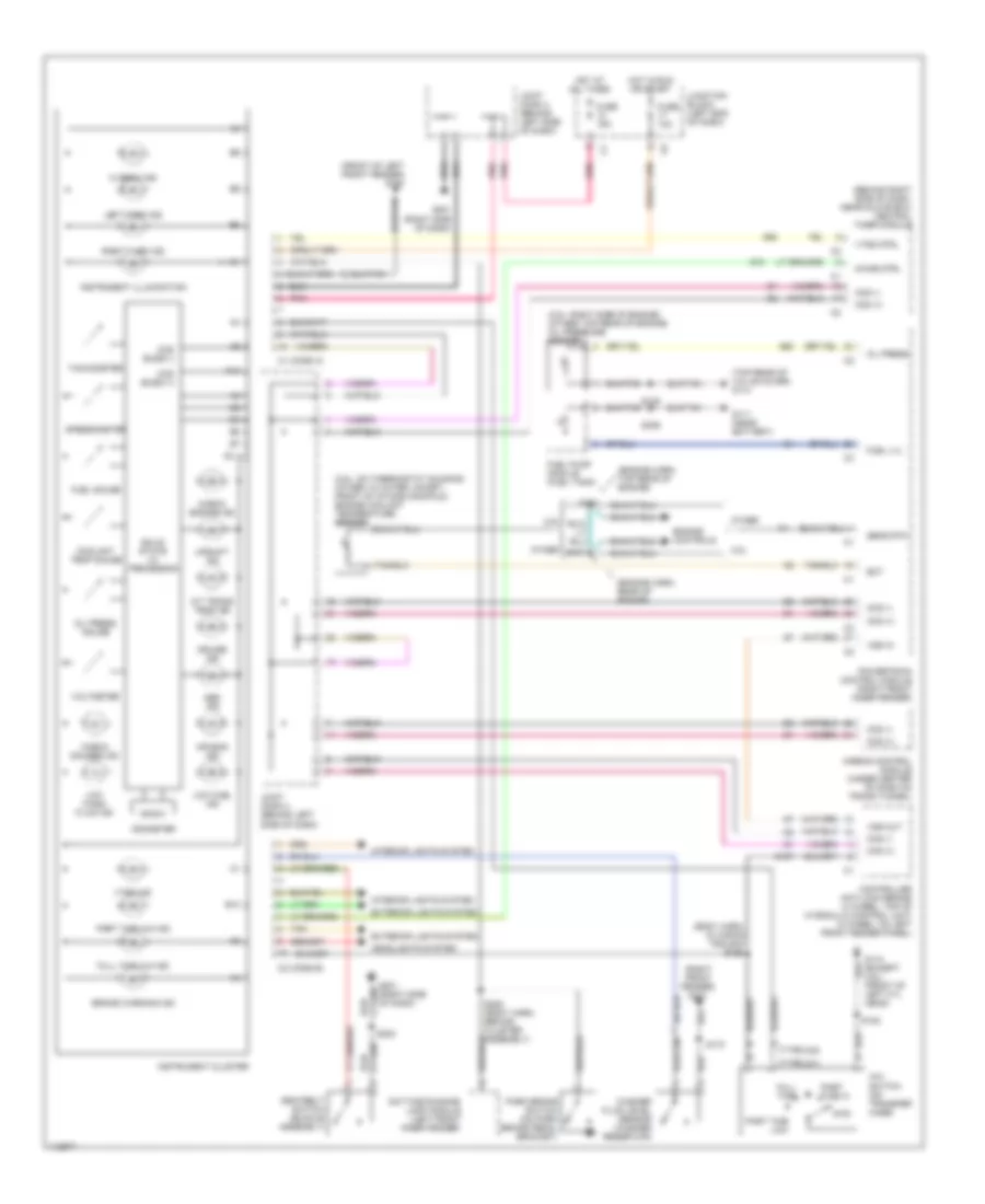
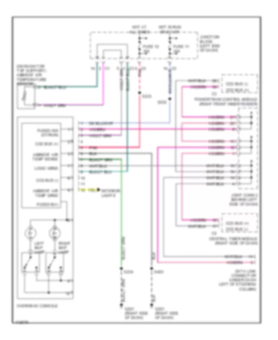
INSTRUMENT CLUSTER Instrument Cluster Wiring Diagram for Dodge Dakota 1999 List of elements for Instrument Cluster Wiring Diagram for Dodge Dakota 1999: 96 (2.5l: on thermostat housing) (other: in water jacket, front of intake manifold) engine coolant temperature sensor (2.5l: right side of engine) (other: top rear of engine) oil pressure sensor (behind right side of dash, near glove box) central timer module (body harn, in wiring trough) s156 (engine harn, rear of engine) (engine harn, top rear of engine) (front of left front fender) g100 (right front fender) g101 (top rear of valve cover) g114 (type 241) (type 242) 2.5l 2wd 4x4 switch (on transfer case) A/t trans temp ind A10 Abs ind Air bag ind Airbag control module (under center of dash on trans tunnel) B10 Brake warning ind C1 (conn a) C2 (conn b) Ccd (+) Ccd (-) Ccd buss (+) Ccd buss (-) Check engine ind Check gauges ind Chime ctrl Controller anti-lock brake (4 wheel: top of hydraulic control unit) (2 wheel: on left front fender panel) Coolant temp gauge Cruise ind Daytime running lamp module (left front inner fender) Ect Engine controls Exterior lights system Fuel gauge Fuel lvl Fuel pump module (fuel tank) Full time Full time 4x4 ind Fuse 10a Fuse 15a G10 G107 G110 (except 2.5l) (front of left cyl head) G111 (near battery) G201 (right side of dash) G52 G60 Headlights system Hi beam ind Hot at all times Hot in run or start Instrument cluster Instrument illumination Interior lights system Joint conn 3 (behind left side of dash) Joint conn 4 (behind left side of dash) Junction block (left end of dash) Left turn ind Low fuel ind Low wash fluid ind Odometer Oil press Oil press gauge Other Park brake switch (on park brake pedal bracket) Part time 4x4 ind Part time hi Part time low Pnk Powertrain control module (right front inner fender) Right turn ind S101 S103 S105 S108 S170 S200 (body harn, behind cluster assembly) S223 S306 Seatbelt switch (buckle assembly) Sens rtn Solid state i/o processor Speedometer Tachometer Tan Upshift ind Voltmeter Vss in Vss out Vtss ctrl Vtss ind Washer fluid level sensor (washer reservoir) Overhead Console Wiring Diagram for Dodge Dakota 1999 List of elements for Overhead Console Wiring Diagram for Dodge Dakota 1999: 28 (on radiator top support) ambient air temperature sensor All times Ambient air temp sense Ccd bus (+) Ccd bus (-) Central timer module (right side of dash) Column) Data link connector (under dash left of steering Fuse 11 10a Fuse 12 15a Fused b(+) Fused ign (st/run) G201 (right side of dash) Hot at Hot in run Interior lights Joint conn 3 (behind left side of dash) Junction block (left end of dash) Left map lamp Or start Overhead console Pnk Powertrain control module (right front inner fender) Right map lamp S232 S233 S234 S403
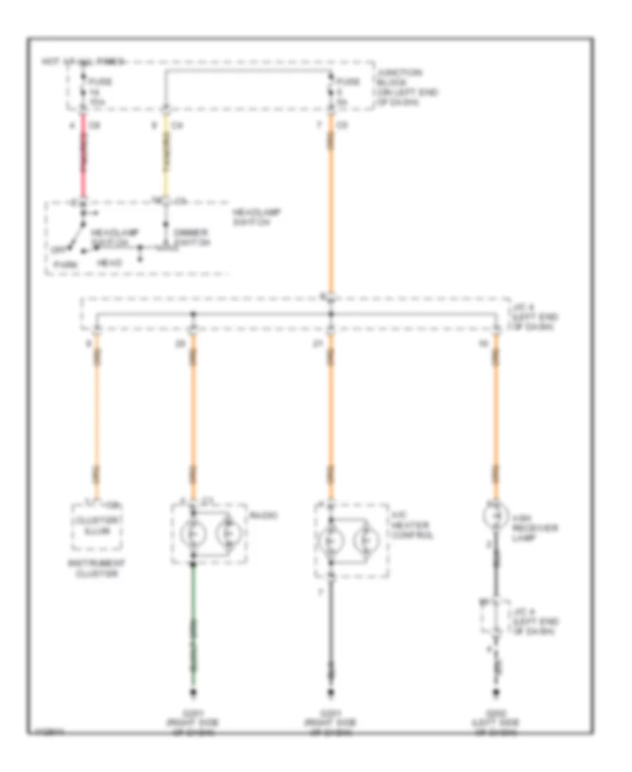
INTERIOR LIGHTS Courtesy Lamps Wiring Diagram for Dodge Dakota 1999 List of elements for Courtesy Lamps Wiring Diagram for Dodge Dakota 1999: 40 (dash harn, behind center of dash) s215 Base Cargo Cargo lamp Central timer module (behind right side of dash, near glove box) Cluster breakouts) Ctsy lamp driver Ctsy lamp switch Dome Dome lamp Door open sense Funeral Fuse 15a G111 (near battery) G202 (left side of dash) Glove box lamp Headlamp switch Hot at all times J/c 4 (left side of dash) Junction block (on left end of dash) Left courtesy lamp Left front door jamb switch (at left "a" pillar) Map lamps Midline Nca Off Other Overhead console Pnk Premium Radio Right courtesy lamp Right front door jamb switch (at right "a" pillar) S113 S206 (dash harn, at breakout to headlamp switch) S233 S334 Underhood lamp and mercury switch W/ low line central timer module Warning systems Instrument Illumination Wiring Diagram for Dodge Dakota 1999 List of elements for Instrument Illumination Wiring Diagram for Dodge Dakota 1999: 18 A/c heater control Ash receiver lamp Cluster illum Dimmer switch Fuse 15a Fuse 5a G201 (right side of dash) G202 (left side of dash) Head Headlamp switch Hot at all times Instrument cluster J/c 4 (left end of dash) Junction block (on left end of dash) Off Park Pnk/red Radio
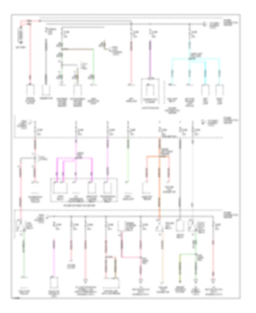
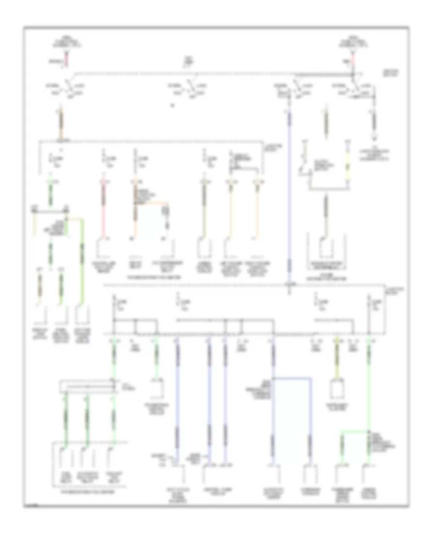
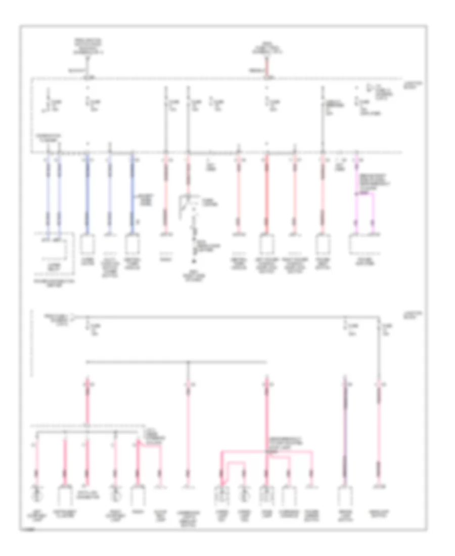
POWER DISTRIBUTION Power Distribution Wiring Diagram (1 of 3) for Dodge Dakota 1999 List of elements for Power Distribution Wiring Diagram (1 of 3) for Dodge Dakota 1999: 64 (diagram 1 of 3) (inside left front fender) s162 (near left fog lamp) s169 (near pdc) s159 A/c compressor clutch relay Auto- matic shut down relay Battery Combination flasher Controller anti-lock brake Daytime running lamp module Downstream heated oxygen sensor Electric brake Engine controls system Engine starter motor Engine starter motor relay Fog lamp relay From fuse 3 b From fuse c (diagram 1 of 3) From s158 (diagram 1 of 3) Fuel pump module Fuel pump relay Fuse 20a Fuse 30a Fuse 40a Fuse 40a (trailer tow) Fuse 50a Fuse a 20a Fuse b 15a Fuse c 20a Fuse d 25a Fuse e 20a Fuse f 20a Fuse g 15a Fusible link 140a Generator Headlamp flasher relay Hevac relay Horn relay J/c 2 (in pdc) Junction block Leak detector pump Left fog lamp Left headlamp Power distribution center Power outlet Powertrain control module Radiator fan relay (2.5l) Red Red/tan Right fog lamp Right headlamp S126 S158 (near pdc) S161 (near pdc) To fuse 1 (diagram 1 of 3) To fuse 2 (diagram 1 of 3) To fuse a (diagram 1 of 3) To ignition switch (pin 4) (diagram 2 of 3) To ignition switch (pin 7) (diagram 2 of 3) To junction block (fuses 4, 13 & circuit breaker 21) (diagram 3 of 3) Trailer tow connector Trailer tow relay Transmission control relay Upstream heated oxygen sensor Power Distribution Wiring Diagram (2 of 3) for Dodge Dakota 1999 List of elements for Power Distribution Wiring Diagram (2 of 3) for Dodge Dakota 1999: 50 (near breakout to steering column) (near junction block) s251 2.5l A/c compressor clutch relay A/t Acc Airbag control module Automatic day/night mirror Automatic shut down relay Back-up lamp switch Base models only C10 Central timer module Circuit breaker 20a Clutch interlock switch Controller anti-lock brake Coolant fan relay Daytime running lamps module Duty cycle evap/ purge solenoid Engine starter motor relay Except 2.5l From fuse 10 (pdc) (diagram 1 of 3) From fuse 9 (pdc) (diagram 1 of 3) Fuel pump relay Fuse 10a Fuse 15a Hevac relay Ignition switch Instrument cluster J/c 1 (in pdc) Junction block Left power window/ door lock switch Lock off M/t Not used Overhead console Park/ neutral position switch Passenger airbag disarm switch Power distribution center Powertrain control module Red Right power window/ door lock switch Run S163 (inside left front fender) S232 (near breakout to overhead console) Start Tan To junction block (fuse 6) (diagram 3 of 3) W/ drl W/o drl Power Distribution Wiring Diagram (3 of 3) for Dodge Dakota 1999 List of elements for Power Distribution Wiring Diagram (3 of 3) for Dodge Dakota 1999: 45 (behind right side of dash, near breakout to door) s225 (near breakout to high mounted stop lamp) s233 Brake lamp switch Cargo lamp no1 Cargo lamp no2 Central timer module Cigar lighter Circuit breaker 20a Combination flasher Data link connector Dome lamp Except base model From fuse 4 (diagram 3 of 3) From fuse 7 (pdc) (diagram 1 of 3) From ignition switch (pin 6) (run/acc) (diagram 2 of 3) Fuse 10a Fuse 15a Fuse 15a (amplifier) Fuse 20a G201 (right side of dash) Glove box lamp Headlamp switch Instrument cluster J/c 4 (near steering column) Junction block Left courtesy lamp Left power window/ door lock switch Multi- function switch (wiper switch) Not used Overhead console Pnk Pnk/red Power amplifier Power distribution center Power mirror switch Power seat switch Radio Red Right courtesy lamp Right power window/ door lock switch S216 (near cigar lighter) To fuse 12 (diagram 3 of 3) Underhood lamp & mercury switch Wiper motor Wiper relay
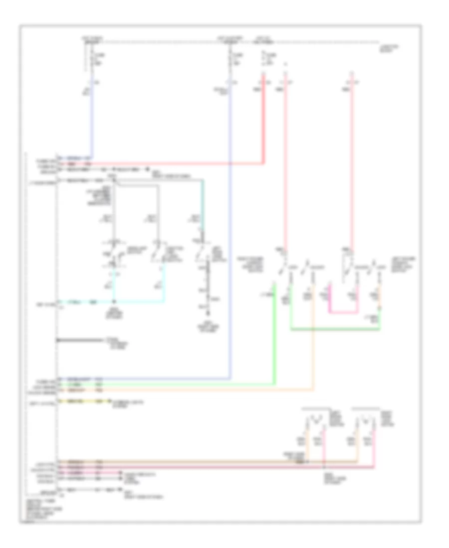
POWER DOOR LOCKS Power Door Lock Wiring Diagram for Dodge Dakota 1999 List of elements for Power Door Lock Wiring Diagram for Dodge Dakota 1999: 50 (right side of dash) s220 Ccd bus + Ccd bus - Central timer module (behind right side of dash, near glove box) Computer data lines system Crty lp ctrl F12 F35 Fuse 10a Fuse 20a Fused b+ Fused ign G16 G201 (right side of dash) G26 Ground Headlamp switch Hot at all times Hot in run or acc Hot in start or run Ignition key lamp/ switch Interior lights system Junction block Key in ign Left door jamb switch Left door lock motor Left power window/ door lock switch Lock Lock ctrl Lock sense Lt door open M20 Nca Off P33 P34 P37 P38 Red Right door lock motor Right power window/ door lock switch Rke antenna (w/ rke) S202 (center of dash) S203 (i/p harness, between cluster breakouts) S222 (right side of dash) S223 S403 Unlock Unlock ctrl Unlock sense
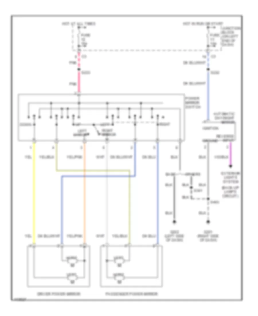
POWER MIRRORS Power Mirror Wiring Diagram for Dodge Dakota 1999 List of elements for Power Mirror Wiring Diagram for Dodge Dakota 1999: 30 (back-up lamps circuit) Automatic day/night mirror Base Down Driver power mirror Exterior lights system Fuse 10a Fuse 15a G201 (right side of dash) G202 (left side of dash) Ground Horiz Hot at all times Hot in run or start Ignition Junction block (on left end of dash) Left Left mirror Others Passenger power mirror Pnk Power mirror switch Reverse input Right Right mirror S232 S233 S301 S403 Vert
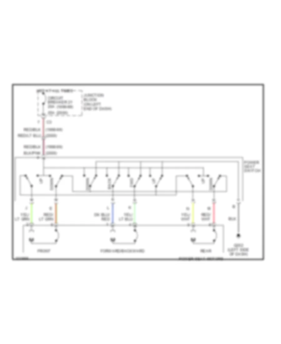
POWER SEATS Power Seat Wiring Diagrams for Dodge Dakota 1999 List of elements for Power Seat Wiring Diagrams for Dodge Dakota 1999: 15 (1998-99) (2000) 25a Back Circuit breaker 21 20a Down Forward/backward Front Fwd G202 (left side of dash) Hot at all times Junction block (on left end of dash) Power seat motors Power seat switch Rear
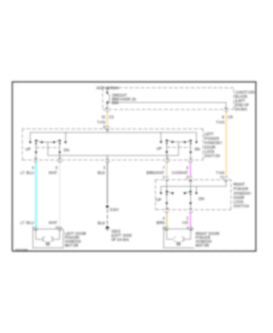
POWER WINDOWS Power Window Wiring Diagram for Dodge Dakota 1999 List of elements for Power Window Wiring Diagram for Dodge Dakota 1999: 10 Circuit breaker 20 20a G202 (left side of dash) Hot in run Junction block (left end of dash) Left door power window motor Left power window/ door lock switch Right door power window motor Right power window/ door lock switch S301 Tan
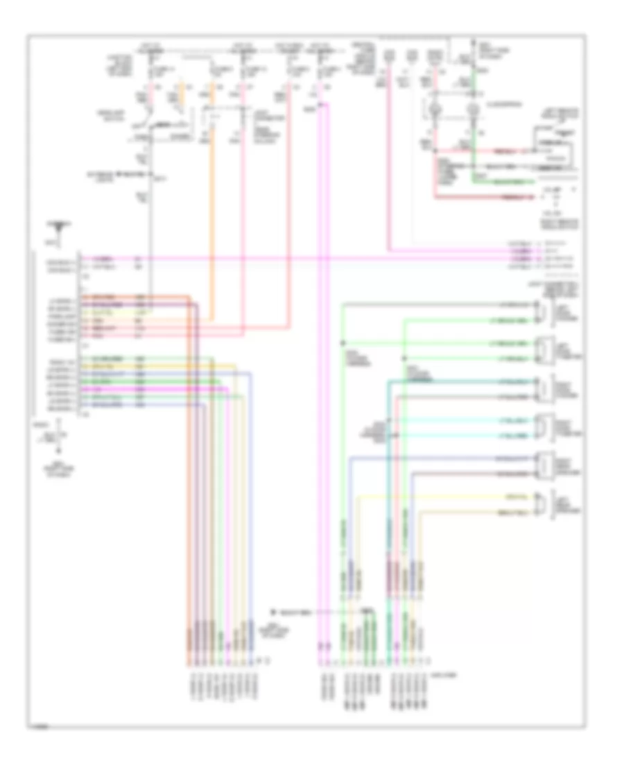
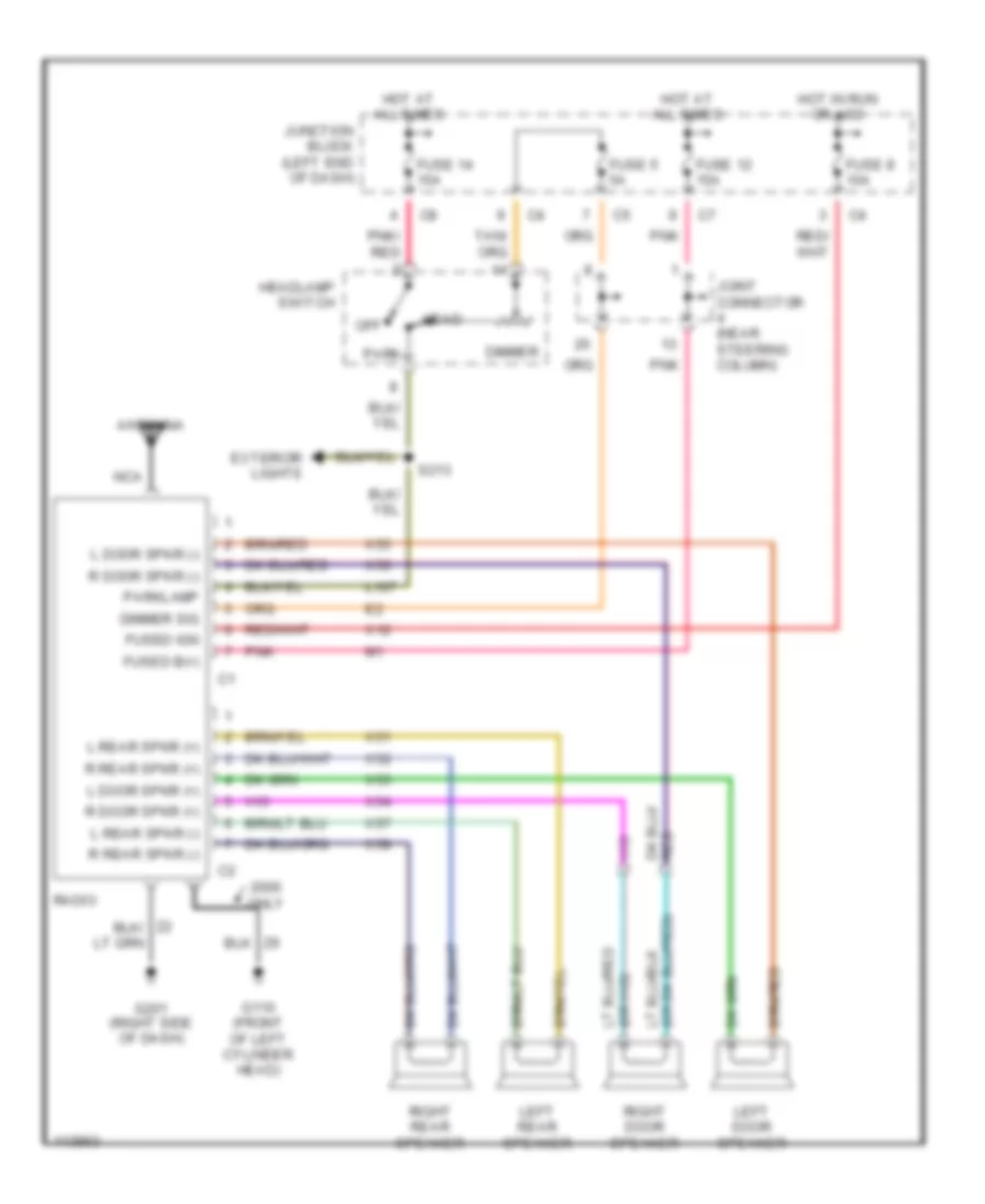
RADIO Radio Wiring Diagrams, with Amplifier for Dodge Dakota 1999 List of elements for Radio Wiring Diagrams, with Amplifier for Dodge Dakota 1999: 91 Amp l door (+) Amp l door (-) Amp l rear (+) Amp l rear (-) Amp r door (+) Amp r door (-) Amp r rear (+) Amp r rear (-) Amplifier Antenna Ccd bus (+) Ccd bus (-) Central timer module (behind right side of dash) Clockspring Dimmer Dimmer sig Exterior lights Fuse 12 15a Fuse 14 15a Fuse 4 15a Fuse 5 5a Fuse 8 10a Fused b(+) Fused ign G201 (right side of dash) Ground Head Headlamp switch Hot at all times Hot in run or acc Joint connector (near steering column) Joint connector 3 (behind left side of dash) Junction block (left end of dash) L front (+) L front (-) L rear (+) L rear (-) L107 Left door tweeter Left door woofer Left rear speaker Left remote radio switch Lf spkr (+) Lf spkr (-) Lr spkr (+) Lr spkr (-) Nca Off Park Parklamp Pnk Pnk/ red Preset R front (+) R front (-) R rear (+) R rear (-) Radio Radio 12v Radio cntrl mux Rf spkr (+) Rf spkr (-) Right door tweeter Right door woofer Right rear speaker Right remote radio switch Rr spkr (+) Rr spkr (-) S207 S208 (steering wheel jumper harn) S213 S223 S225 S240 S330 (in door harness) S331 (in door harness) S333 (in door harness) s332 Seek dn Seek up Vol dn Vol up X12 X51 X52 X53 X54 X55 X56 X57 X58 X60 Radio Wiring Diagrams, without Amplifier for Dodge Dakota 1999 List of elements for Radio Wiring Diagrams, without Amplifier for Dodge Dakota 1999: 49 Antenna Dimmer Dimmer sig Exterior lights Fuse 12 15a Fuse 14 15a Fuse 5 5a Fuse 8 10a Fused b(+) Fused ign G110 (front of left cylinder head) G201 (right side of dash) Head Headlamp switch Hot at all times Hot in run or acc Joint connector (near steering column) Junction block (left end of dash) L door spkr (+) L door spkr (-) L rear spkr (+) L rear spkr (-) L107 Left door speaker Left rear speaker Nca Off Only Park Parklamp Pnk Pnk/ red R door spkr (+) R door spkr (-) R rear spkr (+) R rear spkr (-) Radio Right door speaker Right rear speaker S213 X12 X51 X52 X53 X54 X55 X56 X57 X58
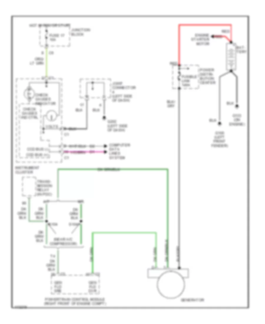
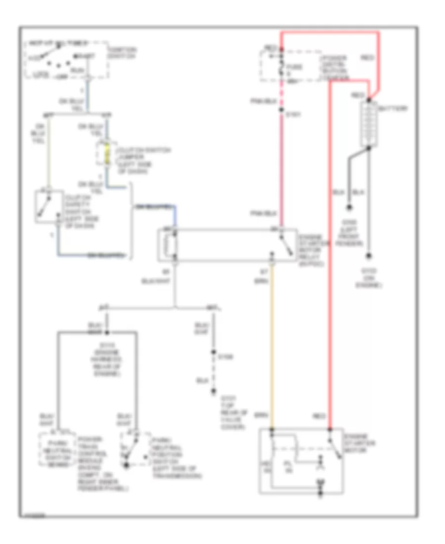
STARTING/CHARGING Charging Wiring Diagram for Dodge Dakota 1999 List of elements for Charging Wiring Diagram for Dodge Dakota 1999: 28 (near a/c compressor) A/t Bat- tery Ccd bus (+) Ccd bus (-) Check gauges ind ctrl Check gauges indicator Computer data lines system Engine starter motor Fuse 17 10a Fusible link 140a G100 (left front fender) G133 (on engine) G202 (left side of dash) Gen fld dvr Gen fld sre Generator Hot in run or start Instrument cluster Joint connector (left side of dash) Junction block M/t Power distri- bution center Powertrain control module (right front of engine compt) Red S104 Trans- mission relay (in pdc) Volts Starting Wiring Diagram for Dodge Dakota 1999 List of elements for Starting Wiring Diagram for Dodge Dakota 1999: 29 A/t Acc Battery Clutch safety switch (left side of dash) Clutch switch jumper (left side of dash) Engine starter motor Engine starter motor relay (in pdc) Fuse 40a G100 (left front fender) G131 top rear of valve cover) G133 (on engine) Hd in Hot at all times Ignition switch Lock M/t Off P/ n Park/ neutral position switch (left side of transmission) Park/ neutral switch sense Pl in Power distri- bution center Power- train control module (in eng compt, on right inner fender panel) Red Run S108 S115 (engine harness, rear of engine) S161 Start
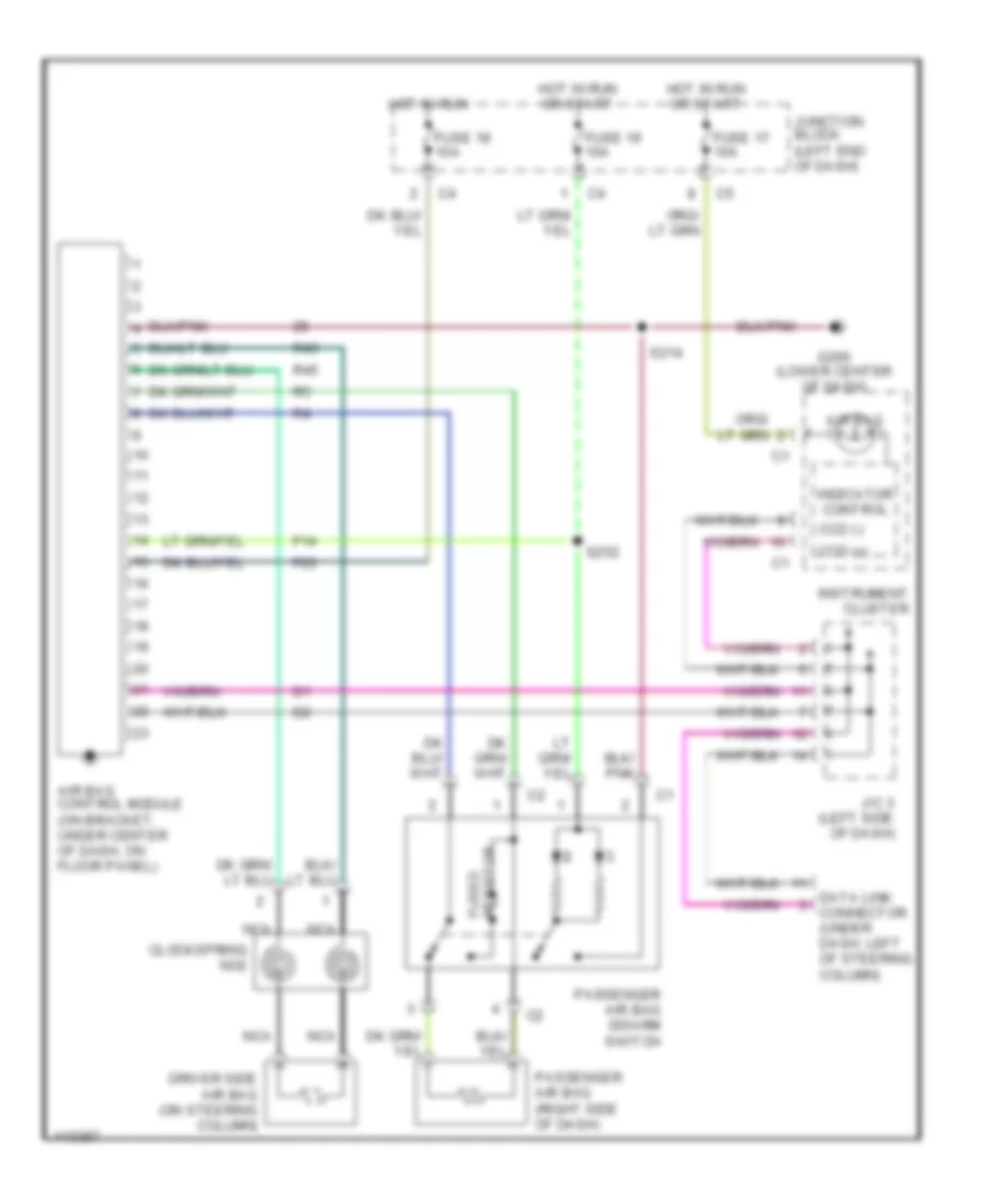
SUPPLEMENTAL RESTRAINTS Supplemental Restraint Wiring Diagram for Dodge Dakota 1999 List of elements for Supplemental Restraint Wiring Diagram for Dodge Dakota 1999: 27 Air bag Air bag control module (on bracket, under center of dash, on floor panel) Ccd (+) Ccd (-) Clockspring no2 Data link connector (under dash, left of steering column) Driver side air bag (on steering column) F14 F23 Fuse 17 10a Fuse 18 10a Fuse 19 10a G206 (lower center of dash) Hot in run Hot in run or start Indicator control Instrument cluster J/c 3 (left side of dash) Junction block (left end of dash) Nca Passenger air bag (right side of dash) Passenger air bag disarm switch R43 R45 Resistor fused S214 S252
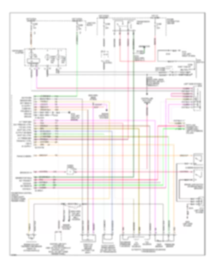
TRANSMISSION A/T Wiring Diagram for Dodge Dakota 1999 List of elements for A/T Wiring Diagram for Dodge Dakota 1999: 95 (eng harn, rear of eng) (eng harn, top left of trans bell- housing) (in pdc) j/c 2 (left side of dash) j/c 3 242t-case 231t-case 2wd 3-4 shift solenoid 4wd switch A/t press sen A/t temp sen A14 Automatic transmission solenoids (transmission) Brake lamp switch (on brake pedal bracket) Brake sw in C1 (black) C2 (white) C3 (gray) Ccd bus + Ccd bus - Controller anti- lock brake (abs: on top of hydraulic control unit, rwal: on left inner fender panel) Controller anti-lock brake D20 D21 Data link connector 1 (under dash, left of steering column) Ect sens in Engine controls system Engine controls systems Engine coolant temperature sensor (front of intake manifold) F18 Full time Full time 4wd ind Fuse 10a Fuse 20a Fuse f 20a Fused b(+) G134 (top left front of eng) G134 (top left front of engine) G202 (left side of dash) Generator Generator field Gov pres sol ctrl Governor pressure solenoid Ground Hot at all times Hot in run and start Hot in run or start I/o Ign power Instrument cluster J/c 2 (in pdc) J/c 4 (left side of dash) Junction block K22 K54 Mil ind Neutral Output shaft speed sensor (on left bottom of transmission) Output ss sens Overdrive switch Part time 4wd ind Part time hi Part time lo Pnk Power distribution center Powertrain control module (in eng compt, on right inner fender panel) Pressure sensor Processor S101 S103 S104 (eng harn, near inj 4) S105 S107 S108 S156 (eng harn, near controller anti- lock brake breakout) S216 Sci receive Sci transmit Sensor grd Shift sol ctrl T13 T14 T25 T34 T60 Tcc sol ctrl Tcc solenoid Temp sensor Throttle position sensor (on throttle body) Tps sens in Trans overdrv Trans rly ctrl Transmission relay V40 Vss in Z12
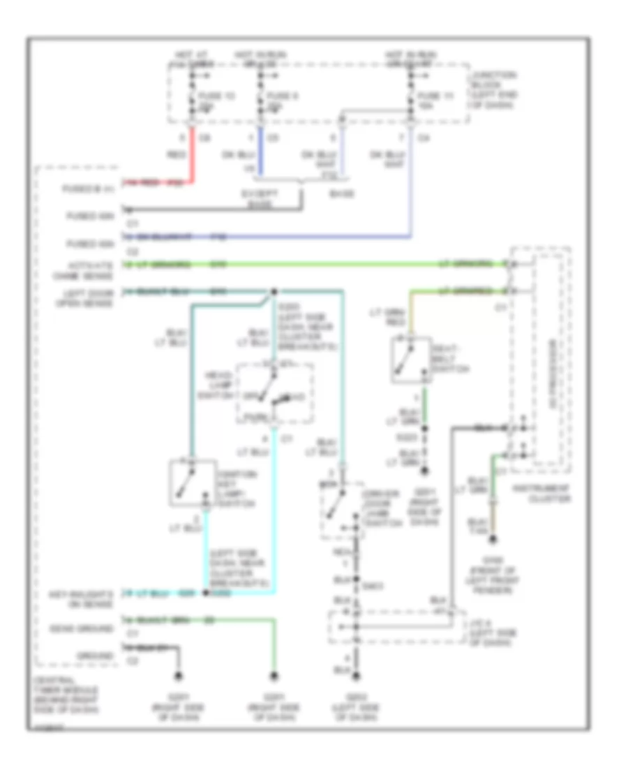
WARNING SYSTEMS Warning System Wiring Diagrams for Dodge Dakota 1999 List of elements for Warning System Wiring Diagrams for Dodge Dakota 1999: 41 (left side dash, near cluster breakouts) s202 Activate chime sense Base Central timer module (behind right side of dash) Driver door jamb switch Except base F12 F35 Fuse 11 10a Fuse 13 20a Fuse 6 20a Fused b (+) Fused ign G10 G100 (front of left front fender) G16 G201 (right side of dash) G202 (left side of dash) G26 Ground Head Head- lamp switch Hot at all times Hot in run or acc Hot in run or start I/o processor Ignition key lamp/ switch Instrument cluster J/c 4 (left side of dash) Junction block (left end of dash) Key-in/lights on sense Left door open sense Nca Off Park Red S203 (left side dash, near cluster breakouts) S223 S403 Seat- belt switch Sens ground
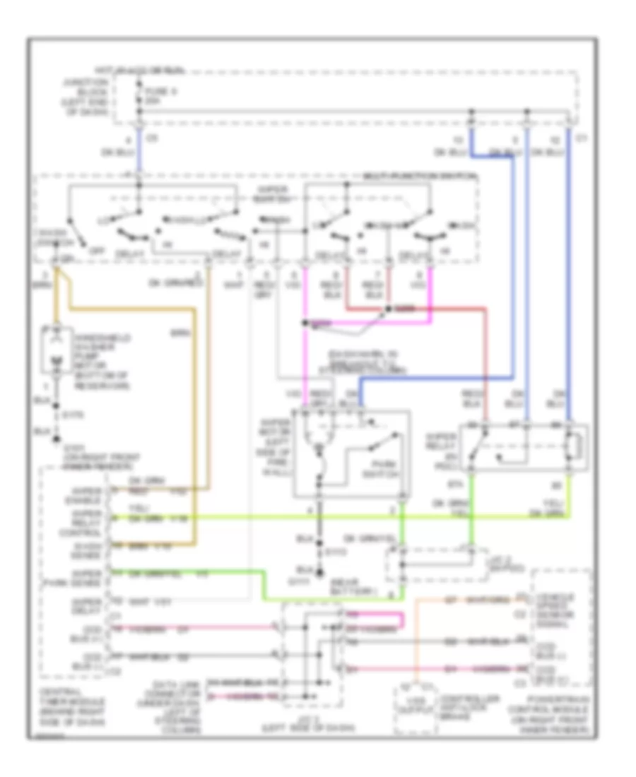
WIPER/WASHER Wiper/Washer Wiring Diagram for Dodge Dakota 1999 List of elements for Wiper/Washer Wiring Diagram for Dodge Dakota 1999: 42 (dash harn, in breakout to steering column) (near battery) 87a Ccd bus (+) Ccd bus (-) Ccd bus (-) c2 Central timer module (behind right side of dash) Controller anti-lock brake Data link connector (under dash, left of steering column) Delay Fuse 6 20a G101 (on right front inner fender) G111 Hot in acc or run J/c 2 (in pdc) J/c 3 (left side of dash) Junction block (left end of dash) Multi-function switch Off Park switch Powertrain control module (on right front inner fender) S113 S170 S204 S205 V10 V18 V51 V52 Vehicle speed sensor signal Vss output Wash Wash sense Wash switch Windshield washer pump motor (bottom of reservoir) Wiper delay c1 Wiper enable Wiper motor (left side of fire- wall) Wiper park sense Wiper relay (in pdc) Wiper relay control Wiper switch