Diagram sections — 28 (85 total)
AIR CONDITIONING ANTI-LOCK BRAKES ANTI-THEFT COMPUTER DATA LINES COOLING FAN CRUISE CONTROL ELECTRONIC SUSPENSION ENGINE PERFORMANCE EXTERIOR LIGHTS GROUND DISTRIBUTION HEADLIGHTS HORN INSTRUMENT CLUSTER INTERIOR LIGHTS NAVIGATION POWER DISTRIBUTION POWER DOOR LOCKS POWER MIRRORS POWER SEATS POWER TOP/SUNROOF POWER WINDOWS RADIO SHIFT INTERLOCK STARTING/CHARGING SUPPLEMENTAL RESTRAINTS TRANSMISSION WARNING SYSTEMS WIPER/WASHER
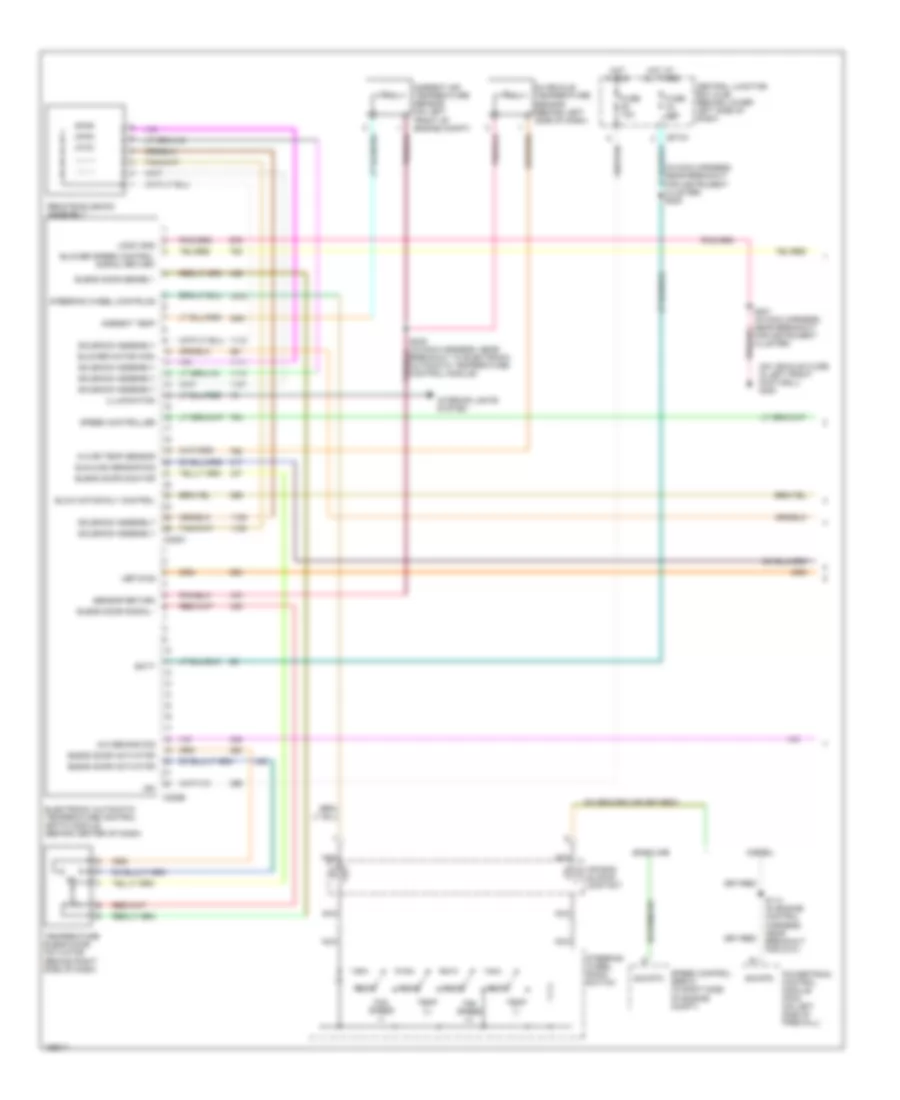
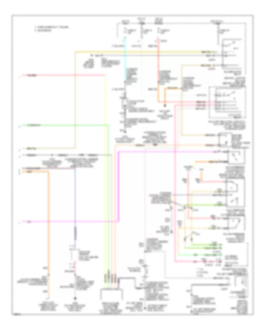
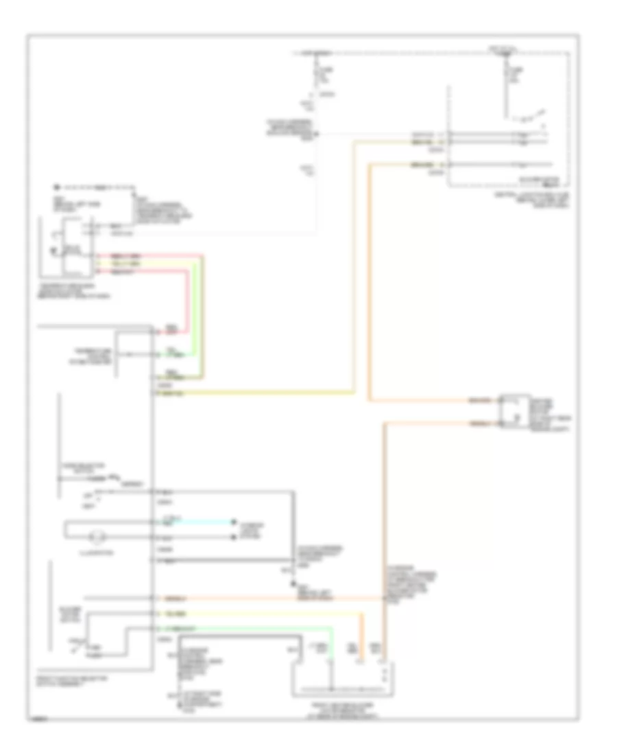
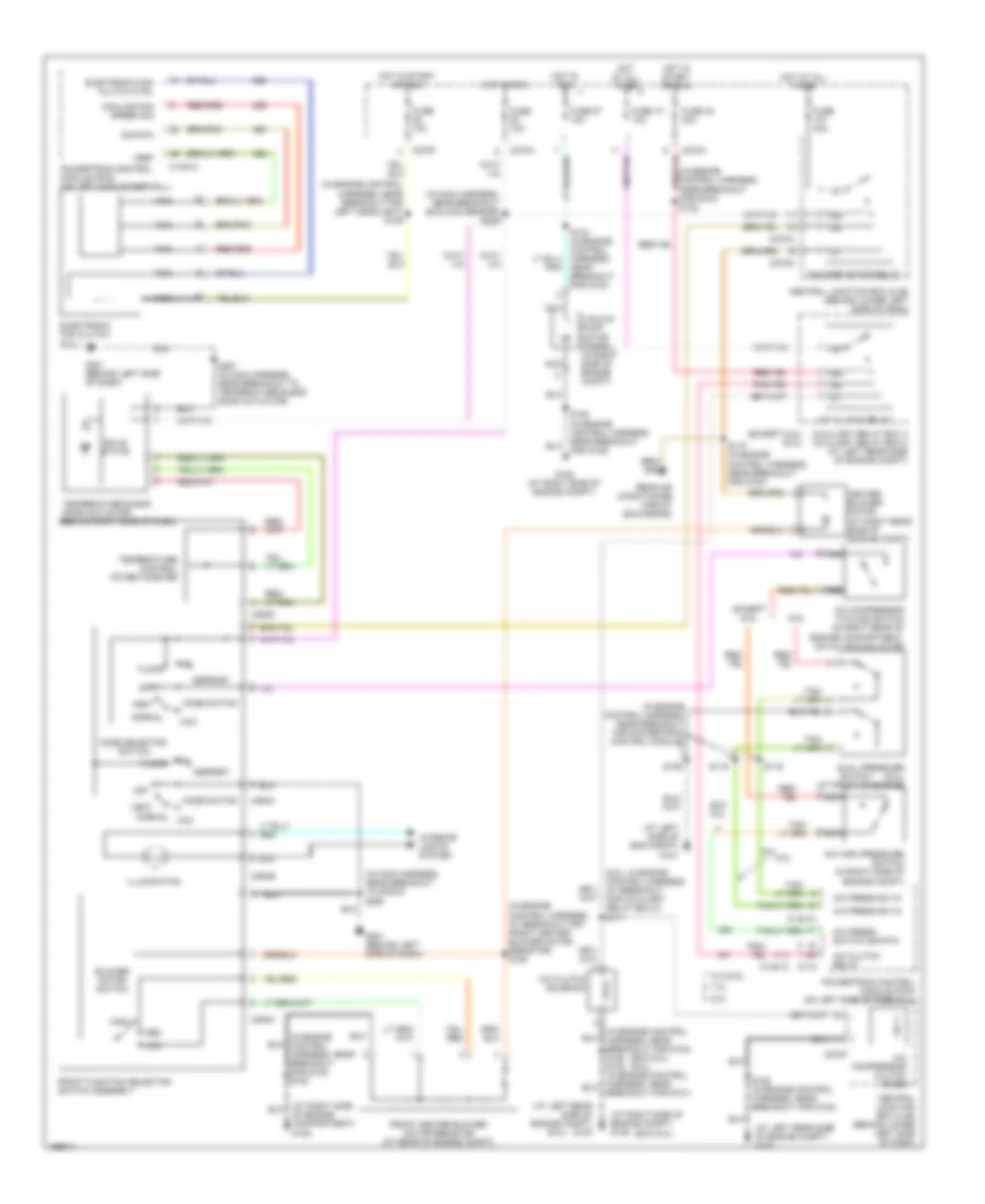
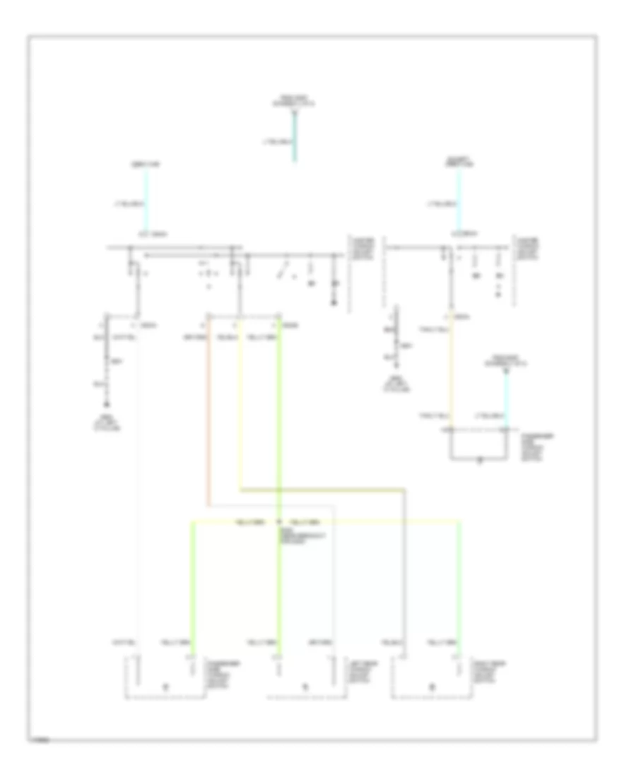
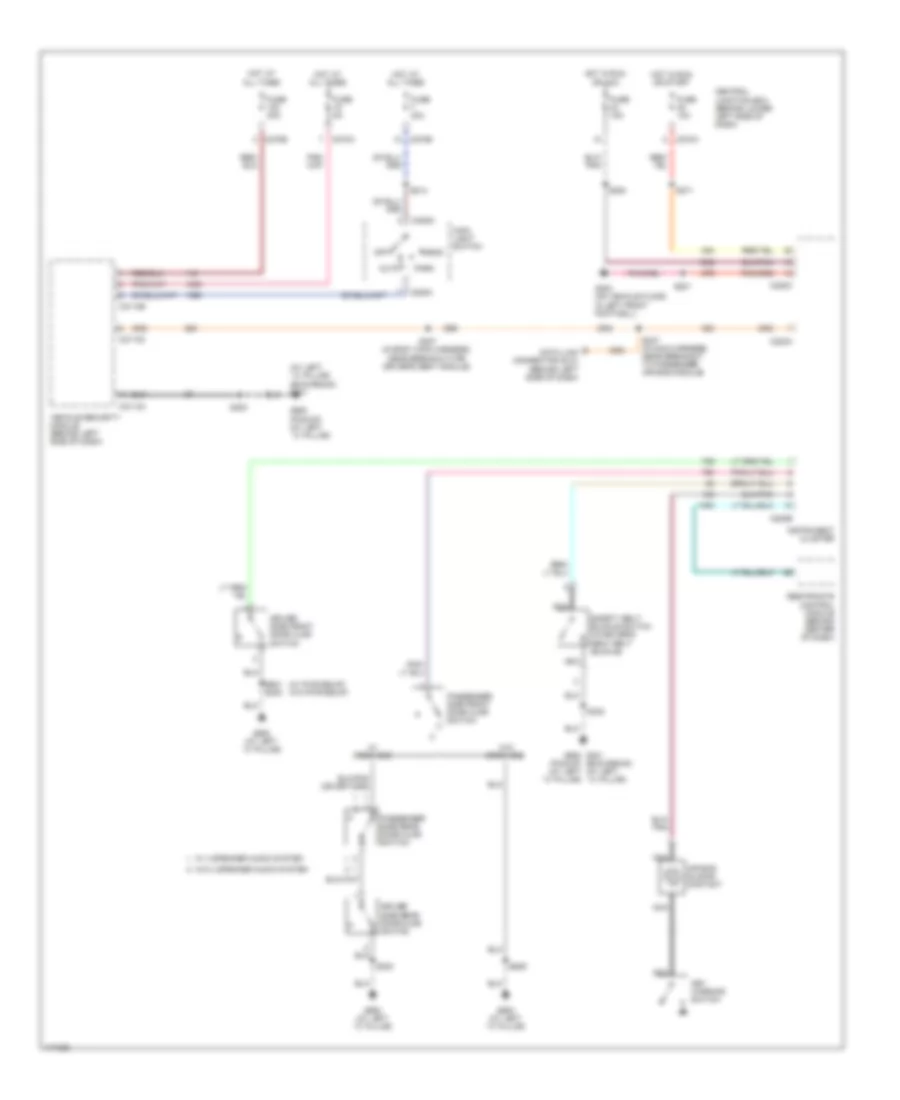
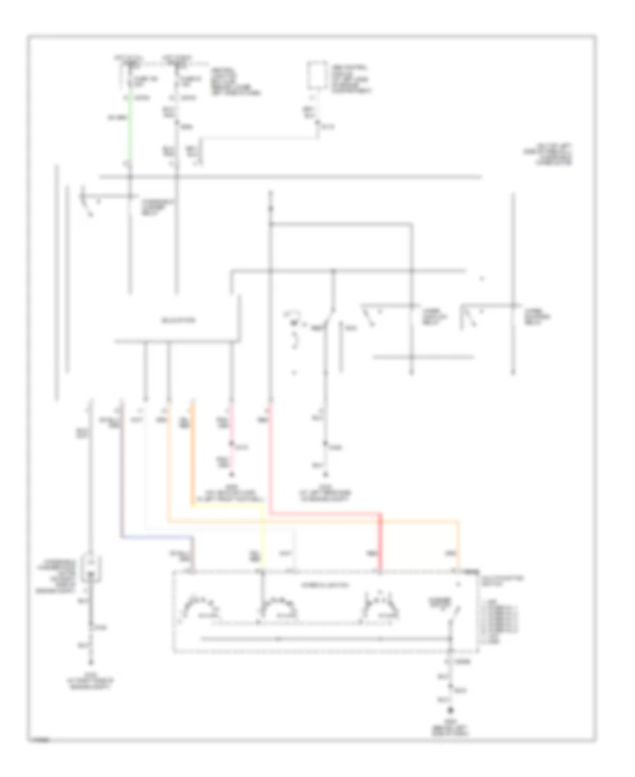
AIR CONDITIONING Automatic A/C Wiring Diagram (1 of 2) for Ford Cab & Chassis F350 Super Duty 2003 List of elements for Automatic A/C Wiring Diagram (1 of 2) for Ford Cab & Chassis F350 Super Duty 2003: 49 (in main harness, near breakout for instrument cluster) s228 (on vehicle floor, in left front footwell) g300 A/c demand sig Air bag sliding contact Ambient air temperature sensor (on left front of engine compt) Ambient temp Batt Blend door actuator Blend door monitor Blend door sense + Blend door signal - Blow motor rly control Blower motor high Blower speed control signal return C228a C228b C270a Central junction box (cjb) (behind lower left side of dash) Diesel Electronic automatic temperature control (eatc) module (behind center of dash) Fan speed (+) Fan speed (-) Fuse 10a Gasoline Hot at all times Hot in run Ign Illumination In car temp sensor In-vehicle temperature sensor (behind left side of dash) Interior lights system Logic gnd Nca Powertrain control module (pcm) (on left side of firewall) Remote solenoid assembly Rest S114 (in engine control harness, near breakout for g101) Sensor return Sig rtn Solenoid assembly Speed control servo (in right side of engine compt) Speed controller Steering wheel contrlos Steering wheel radio switch Sunload sensor sig Temp (+) Temp (-) Temperature blend door actuator (behind right side of dash) Ubp diag Automatic A/C Wiring Diagram (2 of 2) for Ford Cab & Chassis F350 Super Duty 2003 List of elements for Automatic A/C Wiring Diagram (2 of 2) for Ford Cab & Chassis F350 Super Duty 2003: 67 (6.0l) (at left rear side of engine compt) g100 (at left side of eng compt) g101 (at right side of engine compt) g108 (exc 6.0l) (exc 6.0l) (6.0l) (excursion) (ford super duty trucks) (in engine control harness, at breakout for auxiliary relay box 5) s171 (in engine control harness, at breakout for front blower motor speed controller) (in engine control harness, at breakout for front blower motor speed controller) s158 (in engine control harness, near breakout for g100) s122 (in engine control harness, near breakout for g100) s124 (in engine control harness, near breakout for g100) s173 (in engine control harness, near breakout for g108) s180 s102 (in engine control harness, near breakout for g101) (in engine control harness, near breakout for powertrain control module) (on top center of dash) 5.4l/6.8l 6.0l 7.3l A/c clutch relay A/c clutch solenoid A/c compressor clutch diode A/c compressor cycling switch (in right rear of engine compartment, on a/c accumulator) A/c high pressure switch (in right side of engine compt) A/c press switch sig Auxiliary air conditioning circuit Auxiliary relay box 4 (exc 6.0l) auxiliary relay box 5 (6.0l) (at left rear side of engine compt) Blower motor relay C1381a C175 C270a C270f C270g C270h Central junction box (cjb) (behind lower left side of dash) Data link connector (dlc) (behind left side of dash) Dual pressure (6.0l) (at front of engine) Exc 6.0l Except 6.0l For g108) s180 Front blower motor speed controller (at right rear side of engine compt) Fuse 10 10a Fuse 107 40a Fuse 23 20a Fuse 27 15a G108 (at right side of engine compt) G202 (behind left side of dash) G300 (on vehicle floor, in left front footwell) Heater blower motor (at right rear side of engine compt) Hot at all times Hot in run Hot in start or run Instrument cluster) Nca Powertrain control module (pcm) (on left side of firewall) S106 S116 S119 S157 S162 (in engine control harness, near breakout for g100) S191 (in main harness, near breakout for c146) S218 (near breakout for instrument cluster) S247 (in main harness, near breakout to passenger air bag module) Sunload sensor Switch Vacuum pump motor (6.0l) (in right side of engine compartment) Heater Wiring Diagram for Ford Cab & Chassis F350 Super Duty 2003 List of elements for Heater Wiring Diagram for Ford Cab & Chassis F350 Super Duty 2003: 37 (in engine control harness, at breakout for front heater blower motor resistor) s152 (in engine control harness, near breakout for g108) s180 (in main harness, near breakout sunload sensor) s235 (in main harness, near breakout to radio) s290 Blower motor relay Blower motor switch C270a C270g C294a C294b C294c C294d Central junction box (cjb) (behind lower left side of dash) Defrost Floor Front function selector switch assembly Front heater blower motor resistor (at rear of engine compt) Fuse 10a Fuse 40a G201 (behind left side of dash) Heater blower motor (at right rear side of engine compt) High Hot at all times Hot in run Illumination Interior lights system Low Med Mix Mode selector switch Of engine compartment) g108 Off S257 (in main harness, near breakout to temperature blend door actuator) Solid state Temperature blend door actuator (behind right side of dash) Temperature control potentiometer Vent Manual A/C Wiring Diagram for Ford Cab & Chassis F350 Super Duty 2003 List of elements for Manual A/C Wiring Diagram for Ford Cab & Chassis F350 Super Duty 2003: 94 (6.0l) (6.0l: in engine control harness, at breakout for auxiliary relay box 5) s171 (at left rear side of engine compt) g100 (at left side of eng compt) g101 (at right side of engine compt) g108 (exc 6.0l) (exc 6.0l) (6.0l) (except 6.0l) (6.0l) (in engine control harness, at breakout for front heater blower motor resistor) s152 (in engine control harness, near breakout for g100) s122 (in engine control harness, near breakout for g108) s180 (in engine control harness, near breakout for left headlight) s109 (in engine control harness, near breakout for powertrain control module) (in main harness, near breakout sunload sensor) s235 (in main harness, near breakout to radio) s290 5.4l/6.8l 6.0l 7.3l A/c clutch relay A/c clutch solenoid A/c compressor clutch diode A/c compressor cycling switch (in right rear of engine compartment, on a/c accumulator) A/c high pressure switch (in right side of engine compt) A/c press sw in A/c press switch sig rtn Auxiliary relay box 4 auxiliary relay box 5 (at left rear side of engine compt) Blower motor relay Blower motor switch Breakout for g101) C1381a C1381c C175 C270a C270f C270g C270h C294a C294b C294c C294d Central junction box (cjb) (behind lower left side of dash) Cooling fan speed sig Defrost Dual pressure (6.0l) (at front of engine) Electronic fan clutch (6.0l) Electronic fan clutch ctrl Exc 6.0l Except 6.0l Floor Front function selector switch assembly Front heater blower motor resistor (at rear of engine compt) Fuse 10 10a Fuse 10a Fuse 23 20a Fuse 27 15a Fuse 40a G108 (at right side of engine compt) G201 (behind left side of dash) Heater blower motor (at right rear side of engine compt) High Hot at all times Hot in run Hot in start or run Illumination Interior lights system Low Max Med Mix Mode selector switch Mode switch Nca Near breakout for g100) Normal Normal max Of engine compartment) g108 Off Powertrain control module (pcm) (on left side of firewall) Rear air conditioning circuit (excursion) S106 S116 S119 S162 (in engine control harness, near breakout for g100) S173 (in engine control harness, near breakout for g100) S180 (in engine control harness, near breakout for g108) S257 (in main harness, near breakout to temperature blend door actuator) Sig rtn Solid state Switch Temperature blend door actuator (behind right side of dash) Temperature control potentiometer Vacuum pump motor (diesel) (in right side of engine compt) Vent Vref
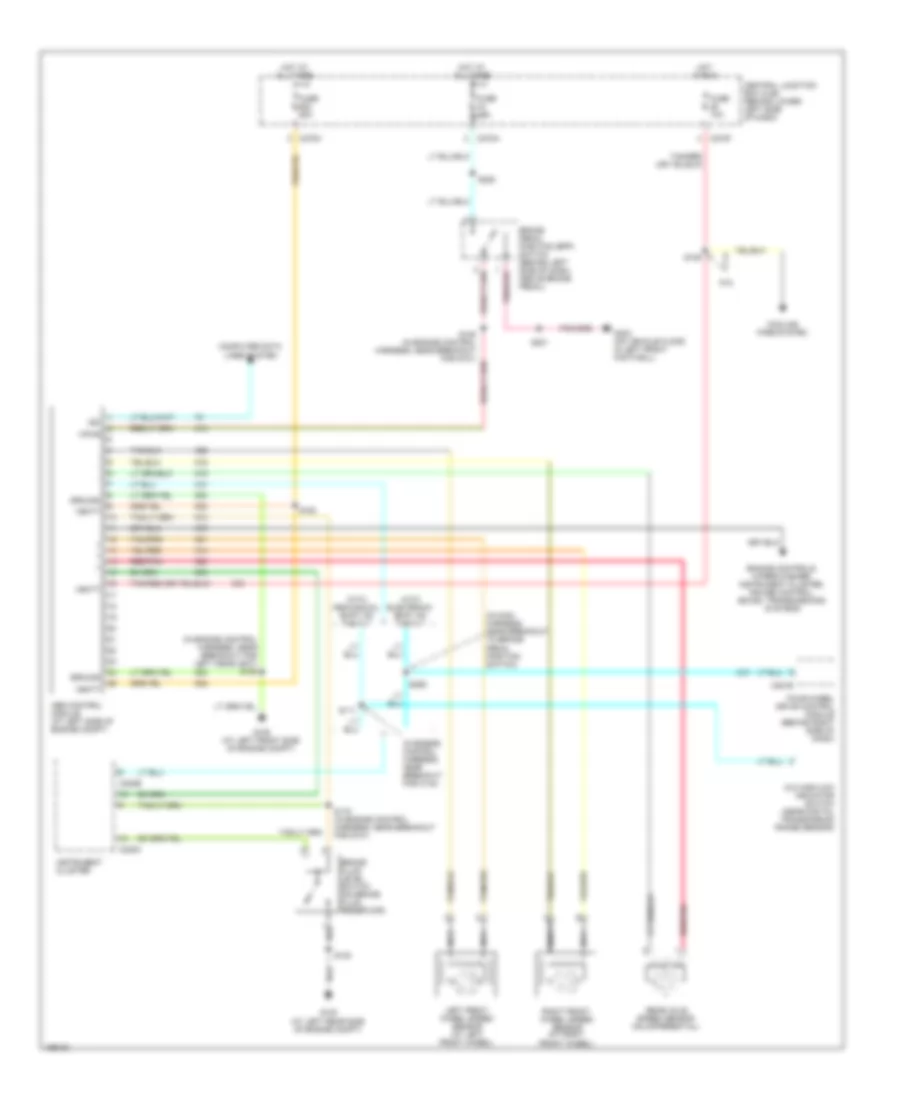
ANTI-LOCK BRAKES Anti-lock Brakes Wiring Diagram for Ford Cab & Chassis F350 Super Duty 2003 List of elements for Anti-lock Brakes Wiring Diagram for Ford Cab & Chassis F350 Super Duty 2003: 46 (in engine control harness, near breakout for c144) (in engine control harness, near breakout for left headlight) s159 (in main harness, near breakout to brake pedal position switch) 4x4 high/low indicator switch (near digital transmission range sensor) 6.0l Abs control module (at left side of engine compt) Brake fluid level switch (on brake fluid reservoir) Brake pedal position (bpp) switch (behind left side of dash, above brake pedal) C220b C220c C270a C270f C270m C281b Central junction box (cjb) (behind lower left side of dash) Computer data lines system Cooling fans system Engine controls, wiper/washer, instrument cluster, cruise control, sound, transmissions systems Four-wheel drive control module (behind right side of dash) Fuse 10a Fuse 60a G100 (at left rear side of engine compt) G105 (at left front side of engine compt) G300 (on vehicle floor, in left front footwell) Ground Hot at all times Hot in run Instrument cluster Iso Left front wheel speed sensor (at left front wheel) Nca Rear axle speed sensor (on differential) Red/pnk Right front wheel speed sensor (at right front wheel) S102 S109 S111 S163 S178 (in engine control harness, near breakout for g101) S201 S228 S259 Vbatt Vpwr With electronic shift on the fly With mechanical shift on the fly
ANTI-THEFT Power Door Locks Wiring Diagram, with Keyless Entry for Ford Cab & Chassis F350 Super Duty 2003 List of elements for Power Door Locks Wiring Diagram, with Keyless Entry for Ford Cab & Chassis F350 Super Duty 2003: 62 (behind (in body main harness, near breakout for c340) (w/ heated seats: near breakout for c3049) (w/0 heated seats: near breakout for c3007) (w/ memory: near breakout for c327) Air conditioning system Autolamps on C2113a C2113b C2113c C270a C270b C270e Central junction box (cjb) (behind lower left side of dash) Diagnostic Door ajar sw Door lock Door lock out Door unlock Dr door relay Driver side door lock switch Driver side front door ajar switch Driver side rear door ajar switch Ext lamp pwr Exterior lights system Fuse 15a Fuse 30a Fuse 5a G201 (behind left side of dash) G900 (at left ``c" pillar) Ground Headlights system Headlmp relay Horn relay Horns system Hot at all times Interior lights system Left front door lock actuator Left rear door lock actuator Left side of dash) data link connector (dlc) Lock Pass- enger side door lock switch Passenger side door lock actuator Passenger side front door ajar switch Passenger side rear door ajar switch Pnk Right rear door lock actuator S214 S233 S272 S290 S300 S304 S305 S307 (in body main harness, near breakout for driver's seat module) S318 (in body main harness, near breakout for g300) S329 (in body main harness, near breakout for g300) S501 S639 Sunload sens Sunload sensor (on top center of dash) Unlock Vbatt Vehicle security module (vsm) (behind left side of dash)
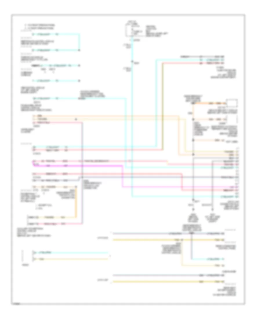
COMPUTER DATA LINES Computer Data Lines Wiring Diagram for Ford Cab & Chassis F350 Super Duty 2003 List of elements for Computer Data Lines Wiring Diagram for Ford Cab & Chassis F350 Super Duty 2003: 53 (in main harness, near breakout for instrument cluster) s225 (near breakout for driver's seat module) s307 (near breakout for restraints control module) (not used) 6.0l Abs control module (at left side of engine compt) Auxiliary powertrain control module (6.0l/7.3l) (behind left center of dash) C1318a C1381a C1381c C1388c C175 C2113c C220a C228b C270d C281a C9013 C930 Central junction box (behind lower left side of dash) Data link connector (dlc) (behind left side of dash) Dvd player Electronic automatic temperature control module (behind center of dash) Except 6.0l Four-wheel drive control module (behind right side of dash) Fuse 12 20a G101 (at left side of engine compt) G202 (behind left side of dash) Hot at all times Injector driver module (at left side of engine compartment) Instrument cluster Nca Overhead console Parking aid module (behind right "c" pillar) Powertrain control module (on left side of firewall) Radio Rear integrated control panel Rear seat entertainment module (in center console) Restraints control module (behind center of dash) S217 S242 S245 (in main harness, near breakout for restraints control module) S246 S247 (near breakout to passenger air bag module) S284 (near breakout for data link connector) S286 (near breakout for data link connector) Shield Tan Vehicle security module (behind left side of dash) W/ roof opening panel W/0 roof opening panel With dvd With vcp
COOLING FAN
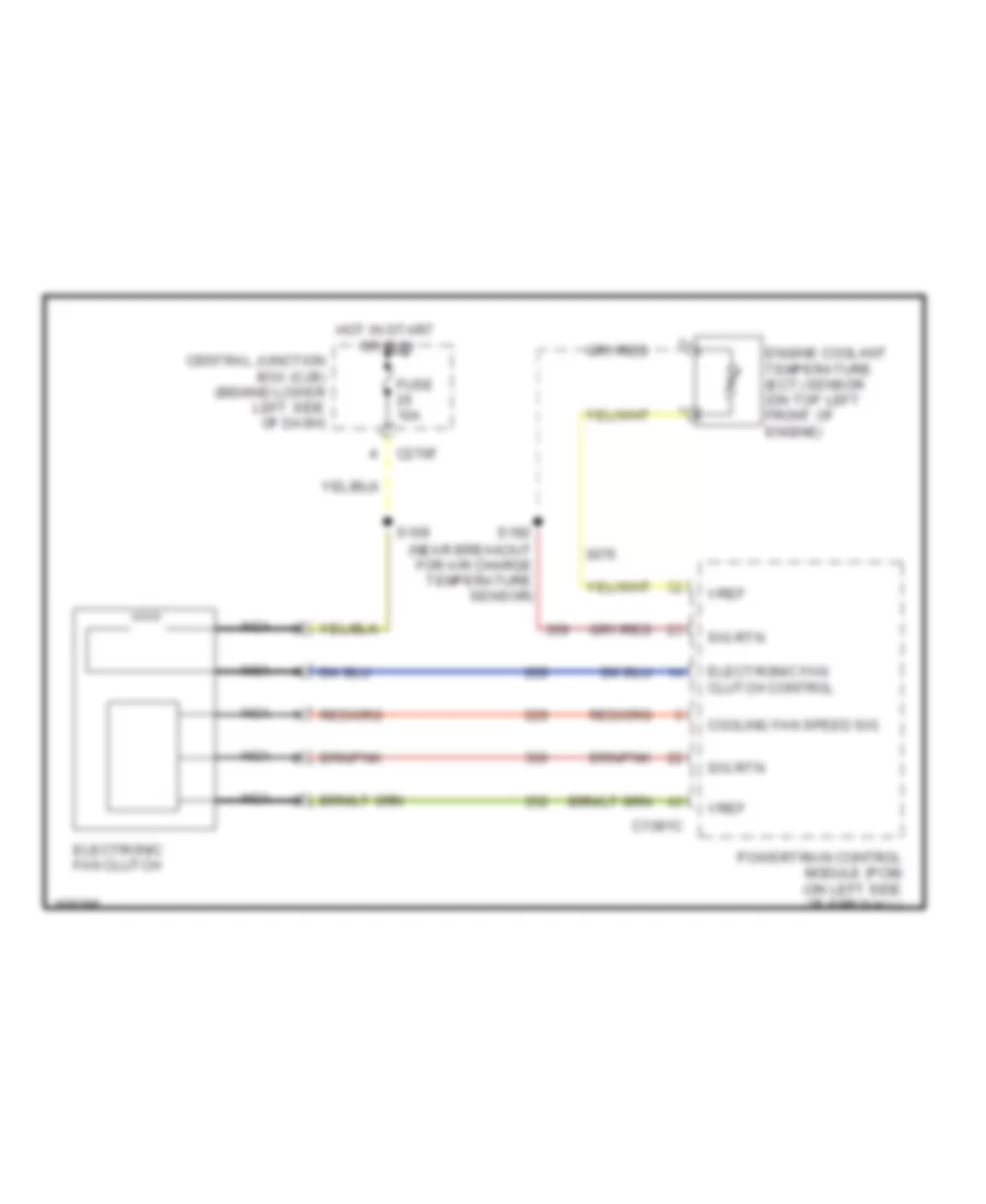
6.0L 6.0L, Cooling Fan Wiring Diagram for Ford Cab & Chassis F350 Super Duty 2003 List of elements for 6.0L, Cooling Fan Wiring Diagram for Ford Cab & Chassis F350 Super Duty 2003: 15 C1381c C270f Central junction box (cjb) (behind lower left side of dash) Cooling fan speed sig Electronic fan clutch Electronic fan clutch control Engine coolant temperature (ect) sensor (on top left front of engine) Fuse 10a Hot in start or run Nca Powertrain control module (pcm) (on left side of firewall) S109 S192 (near breakout for air charge temperature sensor) Sig rtn Vref
CRUISE CONTROL
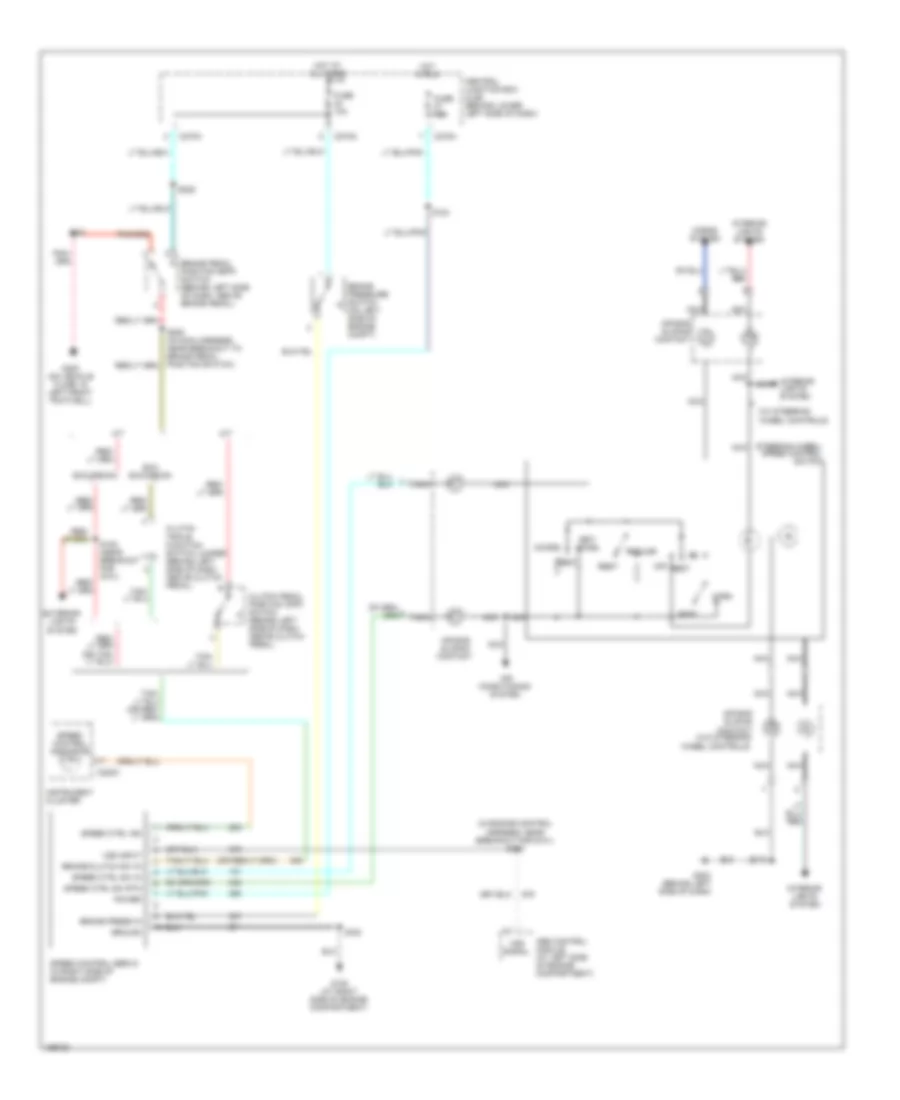
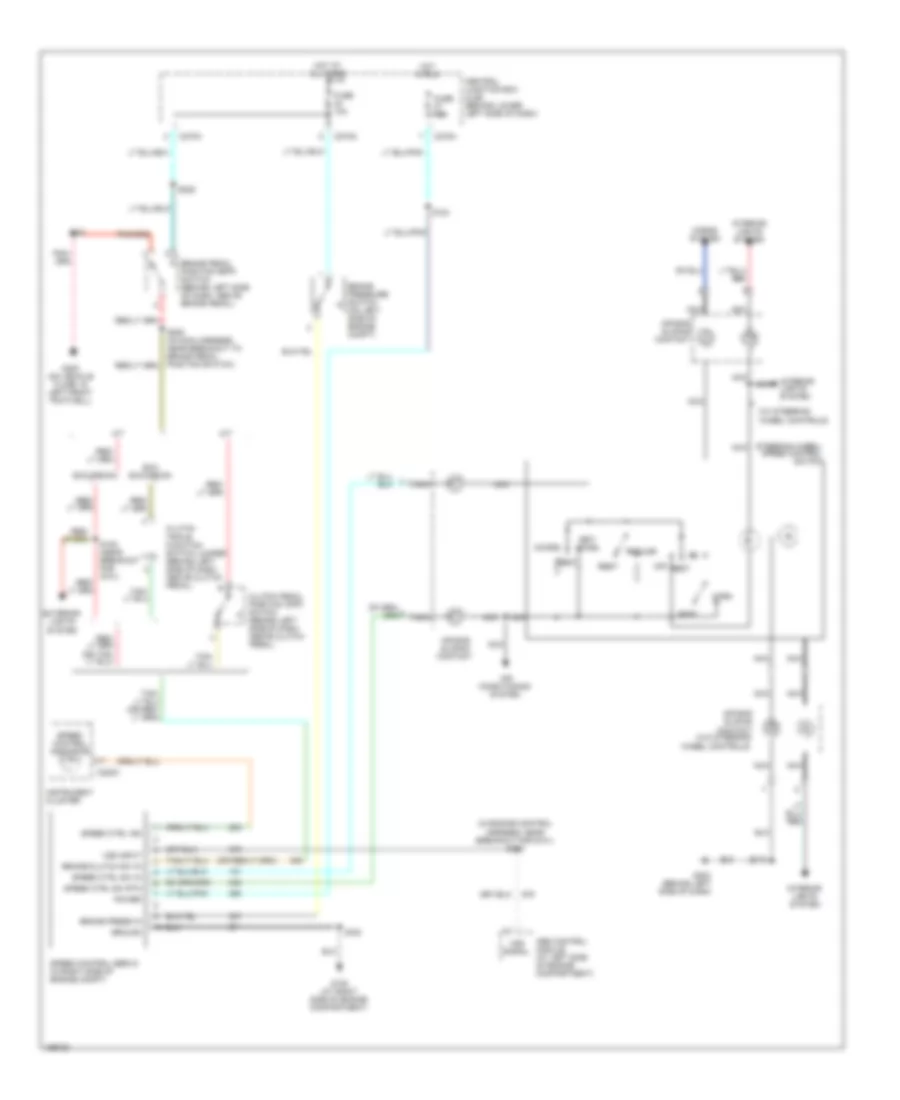
5.4L 5.4L, Cruise Control Wiring Diagram for Ford Cab & Chassis F350 Super Duty 2003 List of elements for 5.4L, Cruise Control Wiring Diagram for Ford Cab & Chassis F350 Super Duty 2003: 57 (in engine control harness, near breakout for g101) s115 (w/ steering wheel controls) A/t Abs control module (at left side of engine compartment) Accel Air bag sliding contact Air bag sliding contact (w/o steering wheel controls) Air conditioning system Brake pedal position (bpp) switch (behind left side of dash, above brake pedal) Brake press in Brake pressure switch (on left side of engine compt) Brake/clutch sw in C220c C270a C270g C270h Central junction box (cjb) (behind lower left side of dash) Clutch pedal position (cpp) switch (behind left side of dash, above clutch pedal) Clutch triple function switch jumper (behind left side of dash, above clutch pedal) Coast Exc excursion Excursion Exterior lights system Fuse 10a Fuse 15a G108 (at right side of engine compartment) G202 (behind left side of dash) G300 (on vehicle floor, in left front footwell) Ground Horn Horns system Hot at all times Hot in run Instrument cluster Interior lights system M/t Nca Off Power Rest Resume S108 (near breakout for g101) S124 S180 S201 S205 (in main harness, near breakout to brake pedal position switch) S218 S228 Set/ Speed control indicator Speed control servo (in right side of engine compt) Speed ctrl ind Speed ctrl sw in Speed ctrl sw rtn Steering wheel/ speed control switch Vss input Vss signal
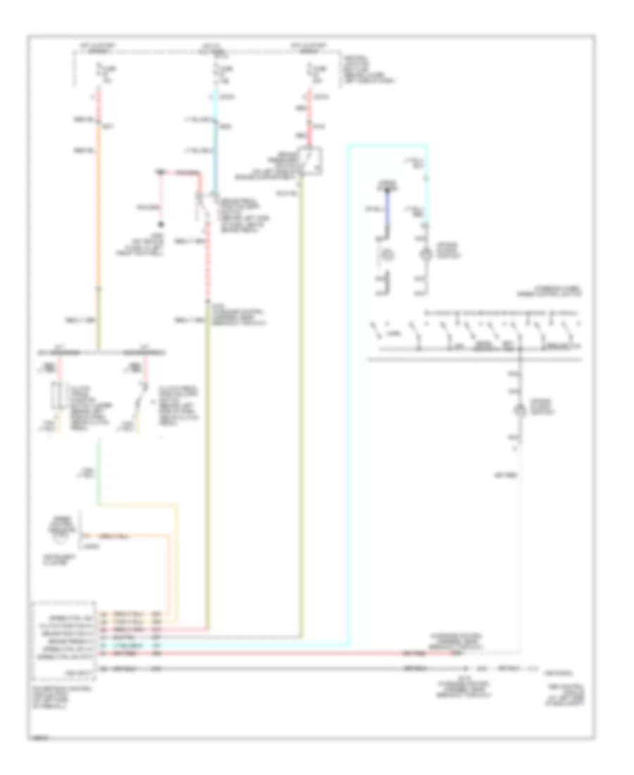
6.0L DIESEL 6.0L Diesel, Cruise Control Wiring Diagram for Ford Cab & Chassis F350 Super Duty 2003 List of elements for 6.0L Diesel, Cruise Control Wiring Diagram for Ford Cab & Chassis F350 Super Duty 2003: 44 Abs control module (at left side of eng compt) Air bag sliding contact Brake pedal position (bpp) switch (behind left side of dash, above brake pedal) Brake position in Brake press in Brake pressure switch (on left side of engine compartment) C1381a C220c C270a C270h Central junction box (cjb) (behind lower left side of dash) Clutch pedal position (cpp) switch (behind left side of dash, above clutch pedal) Coast Fuse 10a Fuse 20a G300 (on vehicle floor, in left front footwell) Horn Hot at all times Hot in start or run Instrument cluster Interior lights system M/t Nca Off Powertrain control module (pcm) (on left side of firewall) Red Rest Resume S108 (in engine control harness, near breakout for g101) S112 (in engine control harness, near breakout for powertrain control module) S115 (in engine control harness, near breakout for g101) S123 S201 S228 S271 Set/ accelerate Speed control indicator Speed ctrl ind Speed ctrl sw in Speed ctrl sw rtn Steering wheel/ speed control switch Vpwr Vss input Vss signal
6.8L 6.8L, Cruise Control Wiring Diagram for Ford Cab & Chassis F350 Super Duty 2003 List of elements for 6.8L, Cruise Control Wiring Diagram for Ford Cab & Chassis F350 Super Duty 2003: 57 (in engine control harness, near breakout for g101) s115 (w/ steering wheel controls) A/t Abs control module (at left side of engine compartment) Accel Air bag sliding contact Air bag sliding contact (w/o steering wheel controls) Air conditioning system Brake pedal position (bpp) switch (behind left side of dash, above brake pedal) Brake press in Brake pressure switch (on left side of engine compt) Brake/clutch sw in C220c C270a C270g C270h Central junction box (cjb) (behind lower left side of dash) Clutch pedal position (cpp) switch (behind left side of dash, above clutch pedal) Clutch triple function switch jumper (behind left side of dash, above clutch pedal) Coast Exc excursion Excursion Exterior lights system Fuse 10a Fuse 15a G108 (at right side of engine compartment) G202 (behind left side of dash) G300 (on vehicle floor, in left front footwell) Ground Horn Horns system Hot at all times Hot in run Instrument cluster Interior lights system M/t Nca Off Power Rest Resume S108 (near breakout for g101) S124 S180 S201 S205 (in main harness, near breakout to brake pedal position switch) S218 S228 Set/ Speed control indicator Speed control servo (in right side of engine compt) Speed ctrl ind Speed ctrl sw in Speed ctrl sw rtn Steering wheel/ speed control switch Vss input Vss signal
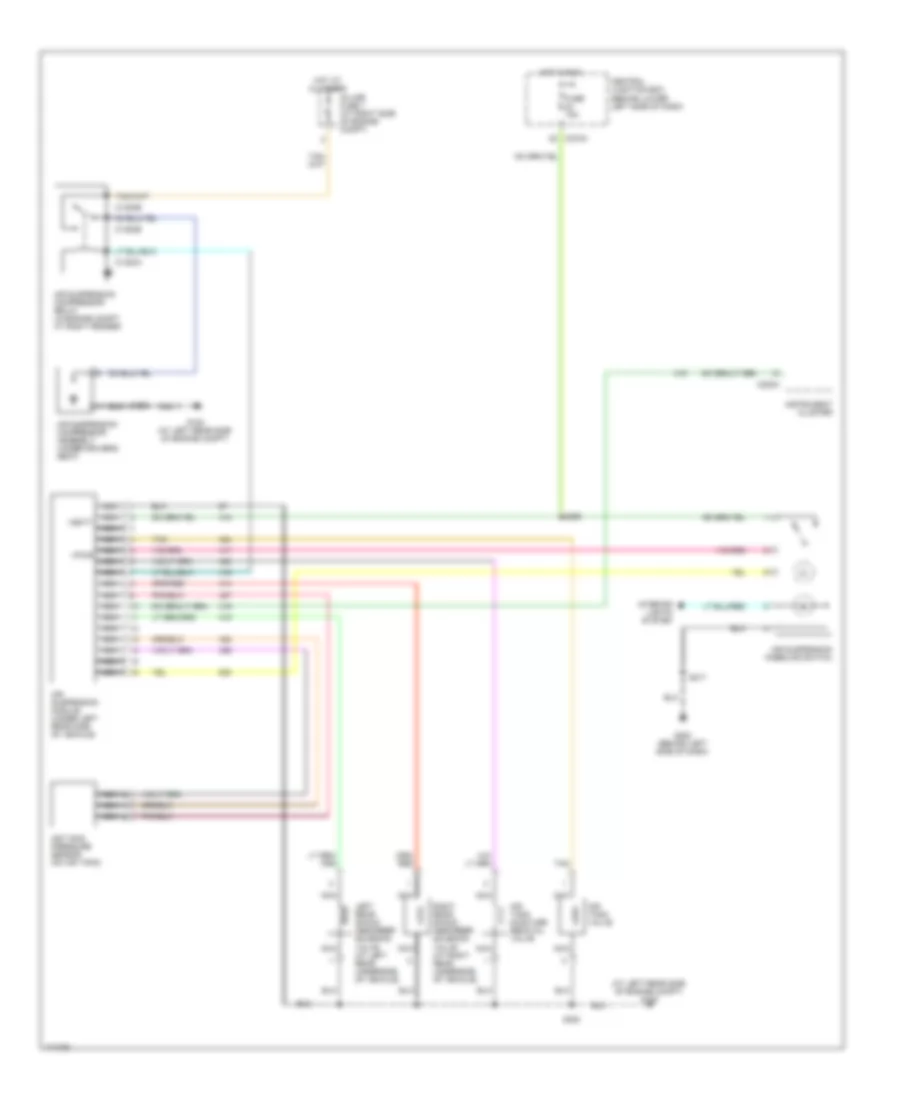
7.3L DI TURBO DIESEL 7.3L DI Turbo Diesel, Cruise Control Wiring Diagram for Ford Cab & Chassis F350 Super Duty 2003 List of elements for 7.3L DI Turbo Diesel, Cruise Control Wiring Diagram for Ford Cab & Chassis F350 Super Duty 2003: 44 (in engine control harness, near breakout for g101) s114 A/t exc excursion Abs control module (at left side of eng compt) Air bag sliding contact Brake pedal position (bpp) switch (behind left side of dash, above brake pedal) Brake position in Brake press in Brake pressure switch (on left side of engine compartment) C220c C270a C270h Central junction box (cjb) (behind lower left side of dash) Clutch pedal position (cpp) switch (behind left side of dash, above clutch pedal) Clutch position in Clutch triple function switch jumper (behind left side of dash, above clutch pedal) Decel- erate Fuse 10a Fuse 20a G300 (on vehicle floor, in left front footwell) Horn Horns system Hot at all times Hot in start or run Instrument cluster M/t exc excursion Nca Off Powertrain control module (pcm) (on left side of firewall) Red Resume S108 (in engine control harness, near breakout for g101) S115 (in engine control harness, near breakout for g101) S123 S201 S228 S271 Set/ acc Speed control indicator Speed ctrl ind Speed ctrl sw in Speed ctrl sw rtn Steering wheel/ speed control switch Vss input Vss signal
ELECTRONIC SUSPENSION Electronic Suspension Wiring Diagram for Ford Cab & Chassis F350 Super Duty 2003 List of elements for Electronic Suspension Wiring Diagram for Ford Cab & Chassis F350 Super Duty 2003: 31 (at left rear side of engine compt) g100 Air suspension compressor assembly (under driver's seat) Air suspension compressor relay (in engine compt, at right fender) Air suspension kneeling switch Air suspension module (under left rear side of vehicle) Air tank moisture removal valve Air tank pressure sensor (on air tank) Air tank valve C1300a C1300b C220a C270a Central junction box (behind lower left side of dash) Fuse 15a G100 (at left rear side of engine compt) G202 (behind left side of dash) Hot at all times Hot in run In-line fuse 1 (at right side of engine compt) Instrument cluster Interior lights system Left rear shock absorber solenoid valve (at left rear underside of vehicle) Nca Right rear shock absorber solenoid valve (at right rear underside of vehicle) S102 S217 S296 S380 Tan Vbatt Vpwr
ENGINE PERFORMANCE
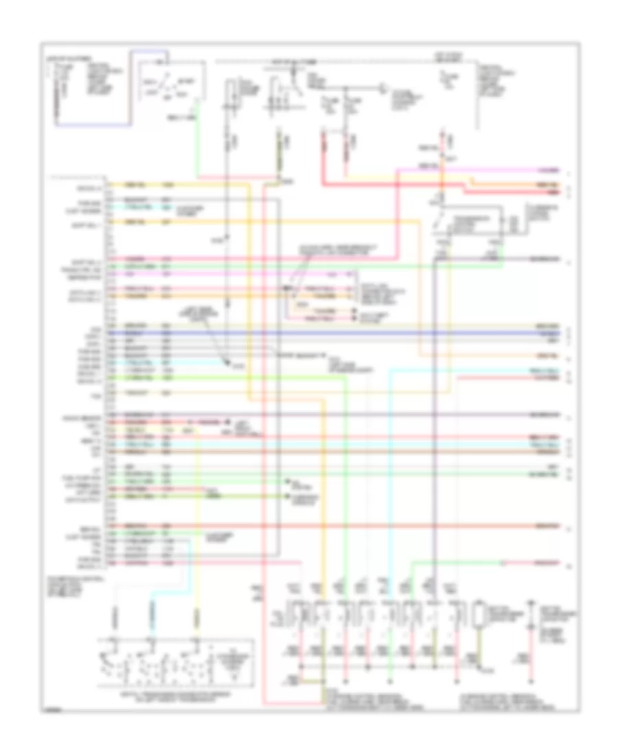
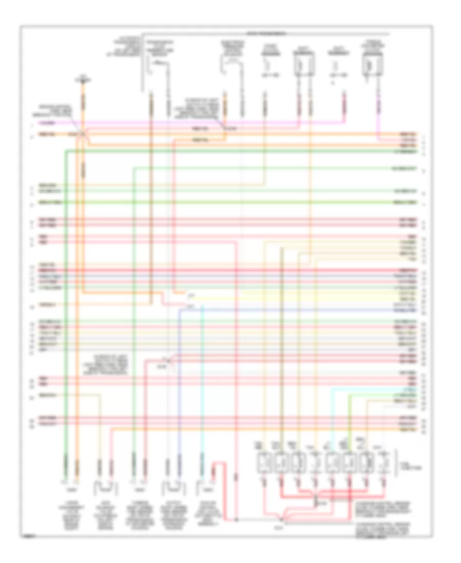
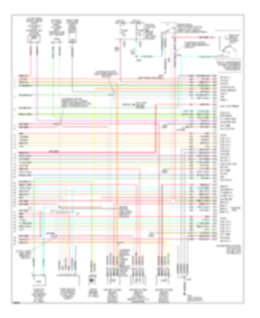
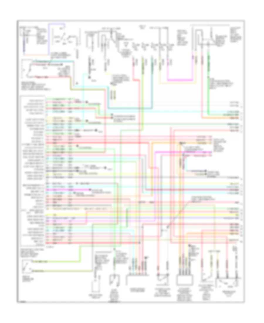
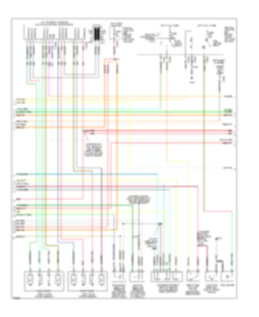
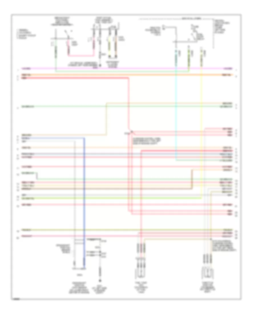
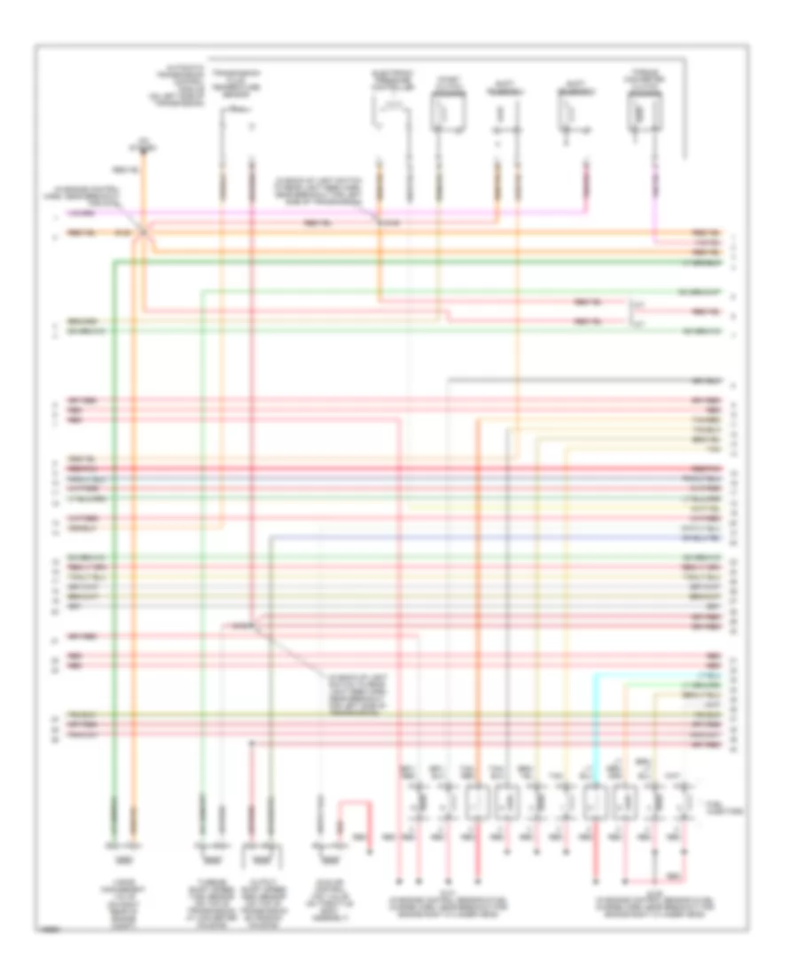
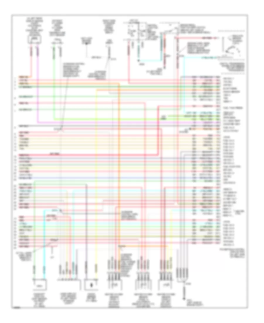
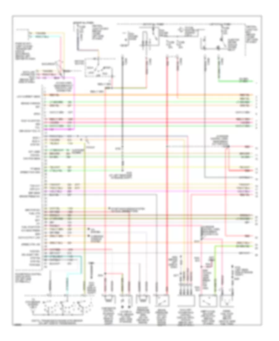
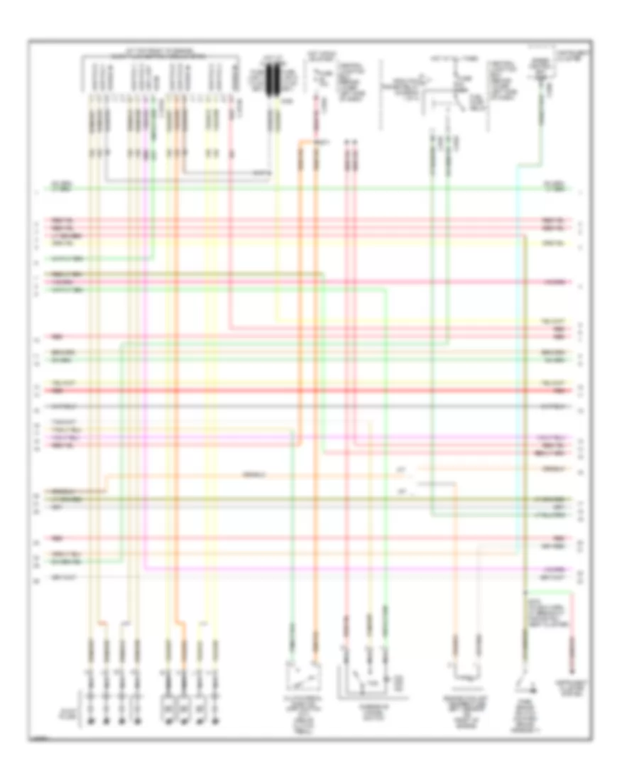
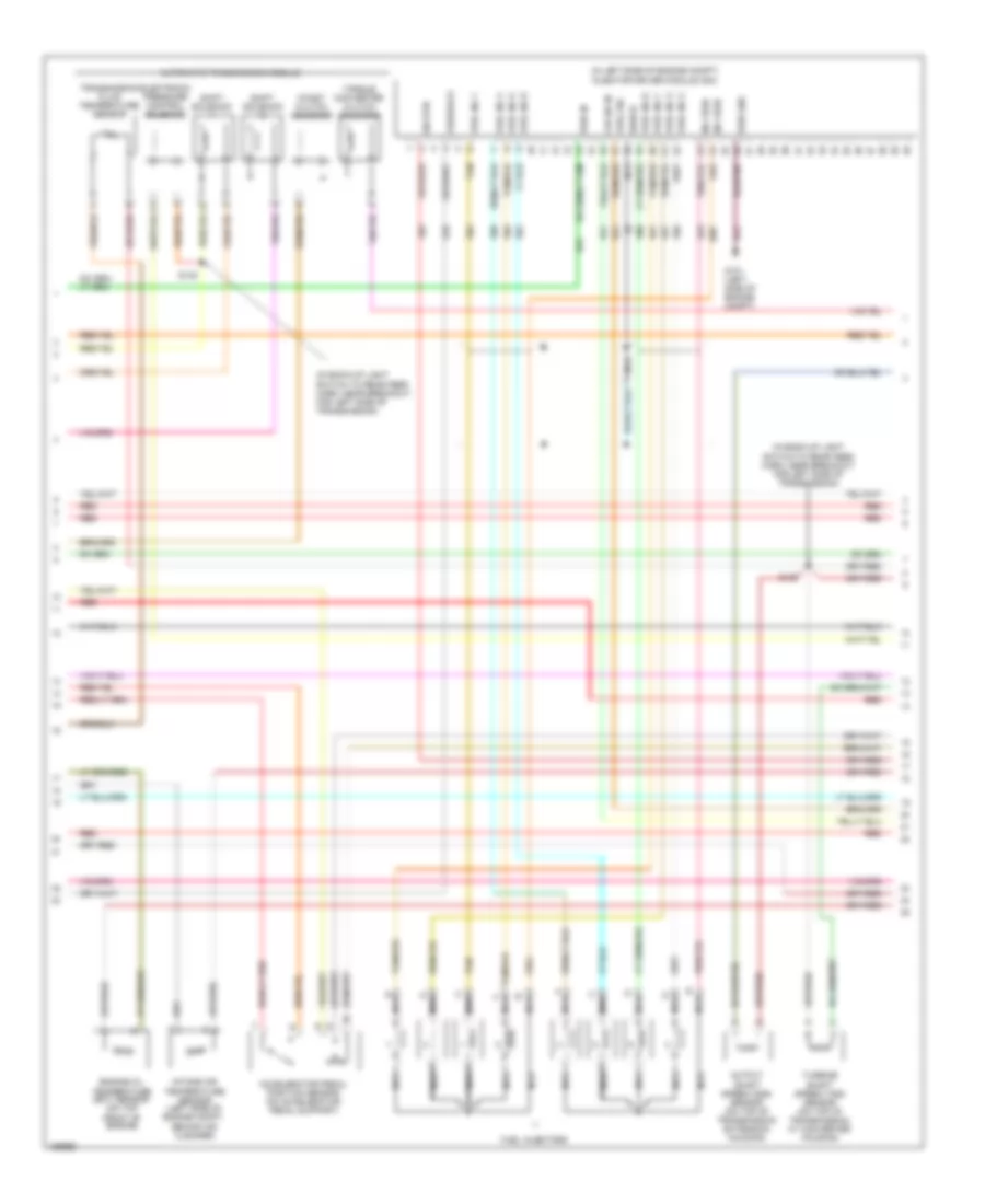
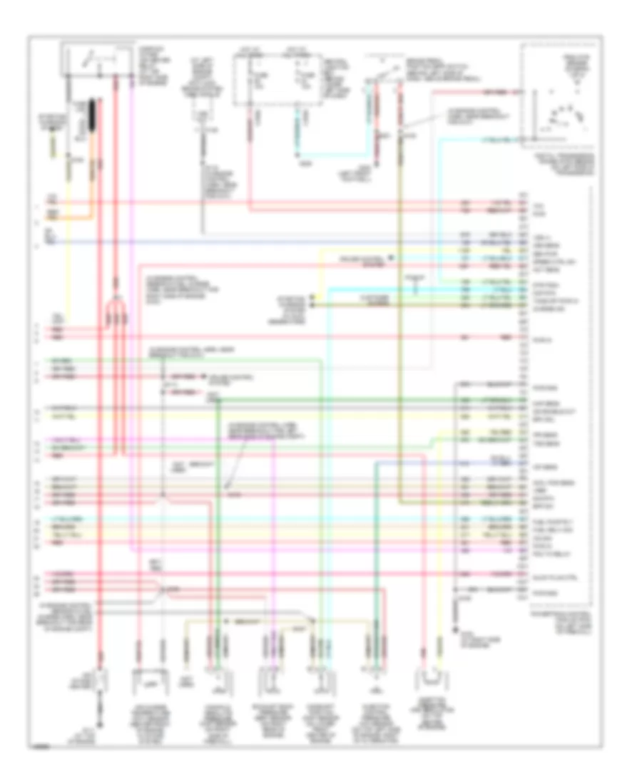
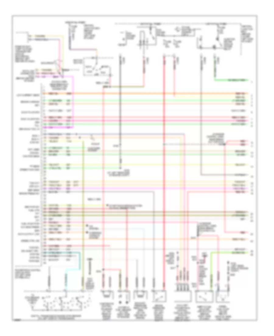
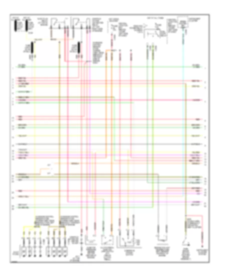
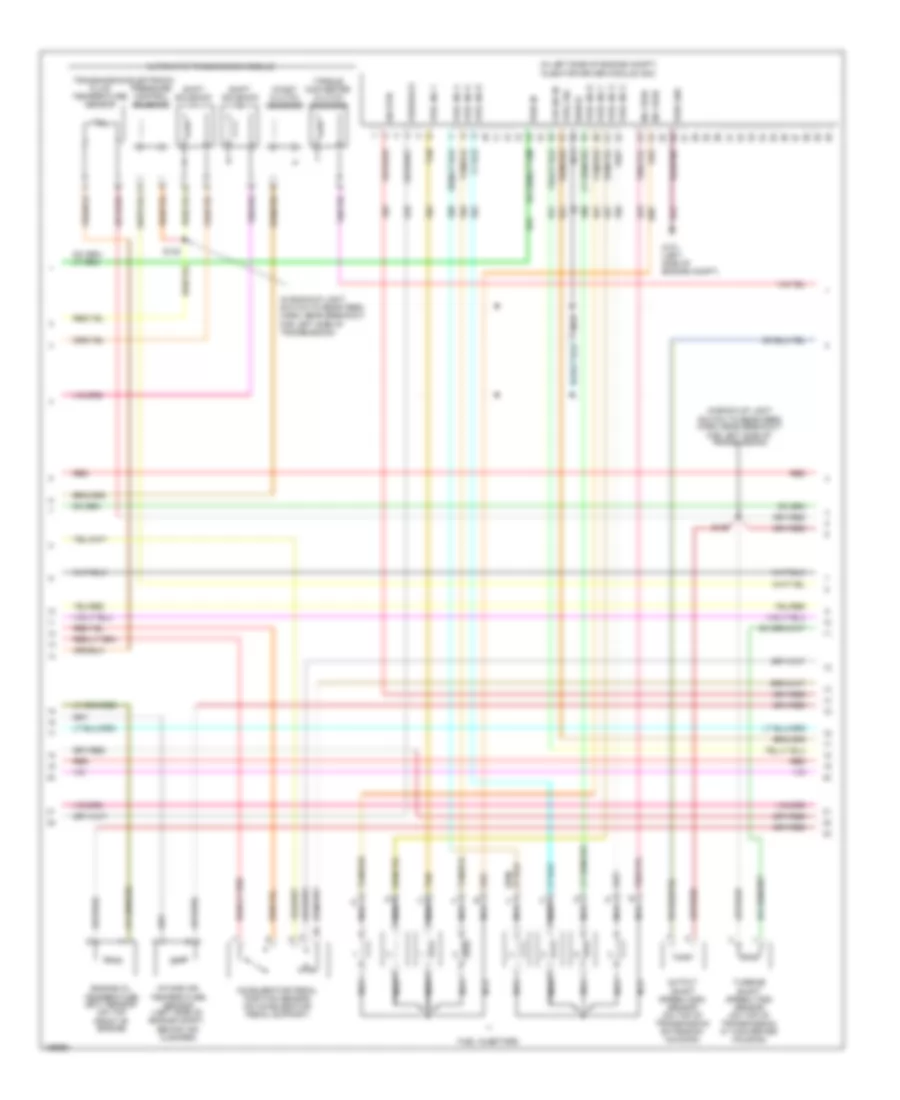
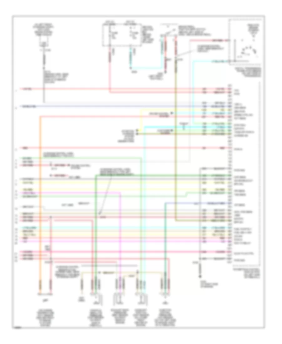
5.4L 5.4L, Engine Performance Wiring Diagram (1 of 4) for Ford Cab & Chassis F350 Super Duty 2003 List of elements for 5.4L, Engine Performance Wiring Diagram (1 of 4) for Ford Cab & Chassis F350 Super Duty 2003: 79 (in engine control sensor & fuel charge harn, near break- out for engine left cylinder head) (in main harn, near breakout for data link connector) (left front g300 footwell) (left rear side of engine compt) (not used) A/c press sw A/c system Acc Anti-theft system C270a Ccs Central junction box (behind lower left side of dash) Ckp(+) Ckp(-) Coil on plug Cust access Customer access Data link (+) Data link (-) Data link connector (dlc) (behind left side of dash) Data output Diag grd Digital transmission range (dtr) sensor (on left side of transmission) Egr sol Fuel pump mon Fuse 10a Fuse 20a Fuse 30a G100 G101 (left side of engine compt) Hego 12 Hot at all times Hot in run or start Iat Ign coil 1 Ign coil 3 Ign coil 5 Ign coil 6 Ignition transformer capacitor Ignition transformer capacitor (on rear of right cyl head) Knock sensor Lock Maf Nca Not used O/d off ind Off Overdrive cancel switch Overhead console Pcm power diode Pcm power relay Powertrain control module (pcm) (on left side of firewall) Pwr gnd R n Red Reprog pwr Run S106 S130 (in engine control sensor & fuel charge harn, near break- out for engine right cylinder head) S135 S162 S201 S258 S271 S284 S286 Shift sol 1 Shift sol 2 Start Tcs Tft To dtr sensor (diagram 4 of 4) To fuel pump relay (diagram 2 of 4) Tr1 Tr2 Tr4 Trans ctrl ind Transmission control switch Vss (-) 5.4L, Engine Performance Wiring Diagram (2 of 4) for Ford Cab & Chassis F350 Super Duty 2003 List of elements for 5.4L, Engine Performance Wiring Diagram (2 of 4) for Ford Cab & Chassis F350 Super Duty 2003: 35 (behind right side of dash) inertia fuel shut-off switch (engine harness, near breakout for left side of engine compt) (part of fuel tank assembly) fuel tank unit C2207 C270a C270f C270h C282 C4033 C433 California Central junction box (behind lower left side of dash) Crankshaft position (ckp) sensor (on lower front center of engine) Crankshaft position sensor shield Differential pressure feedback egr (dpfe) sensor (california) (at top of engine) Except pickup Federal From pcm power relay (diagram 1 of 4) Fuel pump relay Fuel tank unit (california) (at fuel tank) Fuse 20a G101 (left side of engine compt) Hot at all times Instrument cluster system Nca Pickup Red Red/pnk S123 S133 (california) (in engine control sensor & fuel charge harn, near breakout for engine right cylinder head) S145 S161 S167 S401 Throttle position (tp) sensor (on throttle body) 5.4L, Engine Performance Wiring Diagram (3 of 4) for Ford Cab & Chassis F350 Super Duty 2003 List of elements for 5.4L, Engine Performance Wiring Diagram (3 of 4) for Ford Cab & Chassis F350 Super Duty 2003: 32 (engine control harn, near breakout for g100) (in back-up light switch to rear light feed harn, near breakout for left side of transmission) (in engine control sensor & fuel charge harn, near breakout for engine left cylinder head) (in engine control sensor & fuel charge harn, near breakout for engine right cylinder head) (on right rear of engine compt) 4r100 transmission A/c system A/t Automatic transmission module (on left side of transmission) Coast clutch solenoid Electronic pressure control solenoid Evr solenoid valve (california) (on left side of engine) Fuel injectors Idle air control (iac) valve (on throttle body assembly) M/t Output shaft speed (oss) sensor (on top of transmission extension housing) Red Red/pnk S122 S131 S136 S138 S139 Shift solenoid 1 Shift solenoid 2 Tan Tan/ red Tan/red Torque converter clutch solenoid Transmission fluid temperature sensor Turbine shaft speed (tss) sensor (on top of transmission, at converter housing) Vapor management valve 5.4L, Engine Performance Wiring Diagram (4 of 4) for Ford Cab & Chassis F350 Super Duty 2003 List of elements for 5.4L, Engine Performance Wiring Diagram (4 of 4) for Ford Cab & Chassis F350 Super Duty 2003: 86 (a/t) (calif) (engine control harn, near breakout for g101) (in engine control harn, near breakout for g101) (in engine control sensor & fuel charge harn, near breakout for front of engine compt) (in engine control sensor & fuel charge harn, near breakout for right side ex- haust system) (in left rear side of engine compt) (california) evap canister vent control solenoid (in tail lamps harn, near breakout for c311) (not used) (on right cylinder head) cylinder head temperature (cht) sensor (right side of engine compt) speed control servo 5v ref volt A/c cltch rly A/c system A/t Anti-lock brakes system Bpp sw Brake pedal position (bpp) switch (behind left side of dash, above brake pedal) C270a C270g Cam pos in Camshaft position (cmp) sensor (on front of left cyl head) Canister vent Central junction box (behind lower left side of dash) Cyl head temp Digital transmission range (dtr) sensor (on left side of transmission) Dpfe sens Epc sol From dtr sensor (diagram 1 of 4) Fuel inj 1 Fuel inj 2 Fuel inj 3 Fuel inj 4 Fuel inj 5 Fuel inj 6 Fuel inj 7 Fuel inj 8 Fuel pump ctrl Fuel tank press Fuse 10a G101 (left side of engine compt) G300 (left front footwell) Heated oxygen sensor (ho2s) 11 (on right exhaust manifold) Heated oxygen sensor (ho2s) 12 (california) (rear of catalytic converter) Heated oxygen sensor (ho2s) 21 (on left exhaust manifold) Heater ctrl Hego 11 Hego 12 Hego 21 Hot at all times Iac sol Ign coil 2 Ign coil 4 Ign coil 7 Ign coil 8 Kap b(+) Knock sensor Knock sensor (on left cyl head) M/t Maf sens in Mass airflow (maf) sensor (in left front of engine compt) Nca Not used Oss Powertrain control module (pcm) (on left side of firewall) Pwr gnd Red Red/pnk S106 S114 S115 S132 S134 S228 S343 Sig return Tan Tan/red Tcc sol Tp sens in Tr3a (a/t) Tss Vapor valve Vpwr Vss (+) Vss input
6.0L DIESEL 6.0L Diesel, Engine Performance Wiring Diagram (1 of 5) for Ford Cab & Chassis F350 Super Duty 2003 List of elements for 6.0L Diesel, Engine Performance Wiring Diagram (1 of 5) for Ford Cab & Chassis F350 Super Duty 2003: 103 (a/t) (bap) sens mon (in engine control harn, near breakout for c1047) (in engine control harn, near breakout for g101) (in fog jumper harn, near break- out for c1045) (in main harn, near breakout for dlc) (in main harn, near breakout to brake pedal support) s224 (m/t) (maf) sens out (map) sens mon (not used) (scp) data - (scp) data+ A/c clutch input A/c clutch rly A/c system A/t Abs control module Acc Apps monitor 1 Apps monitor 2 Apps monitor 3 Apps ref volt 2 Apps sig rtn 2 Auxiliary powertrain control module (apcm) (behind left side of dash) Auxiliary relay box 5 (at left rear side of engine compt) Brake ped pos sw Brake pedal position (bpp) switch (behind left side of dash, above brake pedal) Brake press sw in Brake pressure switch C135 C1381a C270h red Can bus 1h Can bus 1l Central junction box (behind lower left side of dash) Chassis gnd Clutch pedal position (cpp) switch (m/t) (above clutch pedal) Computer data lines system Cruise control system Cust acc tp sig Cust acc vss out Data link connector (dlc) (behind left side of dash) Data output link Fuel pmp rly Fuel pump monitor Fuse 10a Fuse 20a Fuse 2a Fuse 30a Fuse 50a G100 G101 G300 (on vehicle floor, in left front footwell) Gen/bat ind Grade/load switch (a/t) Grd/load sw (cpp) sw Hot at all times Hot in run Injector driver module power relay Intk air temp sens Lock M/t Maf sens sig rtn Mass airflow (maf) sensor Mod prog sig Nca Off Overhead console Park brake switch (on park brake assembly) Park brk sw input Pcm power diode Pcm power relay Powertrain control module (pcm) (on left fender, near battery) Pto ctrl Pwr Pwr gnd Pwr in Red Ref volt Run S101 S106 S114 S120 (in engine control harn, near breakout for auxiliary relay box 5) S123 S174 S217 S284 S286 Sig rtn Sig rtn spd ctrl Speed ctrl ind Speed ctrl sw in Start Start rly ctrl Starting/ charging system Starting/charging system Tach output To fuel pump relay (diagram 2 of 4) Vss input Water in fuel sens Water in fuel sensor (at top right side of engine) 6.0L Diesel, Engine Performance Wiring Diagram (2 of 5) for Ford Cab & Chassis F350 Super Duty 2003 List of elements for 6.0L Diesel, Engine Performance Wiring Diagram (2 of 5) for Ford Cab & Chassis F350 Super Duty 2003: 52 (at top front of engine) glow plug control module (gpcm) (in engine con- (in engine control harn, near breakout for left rear side of engine compt) (in main harn, near breakout Accelerator pedal position sensor (on accelerator pedal support) Barometric absolute pressure (bap) sensor (behind left side of dash) C1273a C1273b C220c C270a C270f Central junction box (behind lower left side of dash) Ctrl set lamp For c212) s223 From pcm a power relay (diagram 1 of 4) Fuel heater Fuel heater relay Fuel pump (near left side of trans- mission) Fuel pump relay Fuse 10a Fuse 20a Fuse 30a G100 Glow plugs Glw plg 1 Glw plg 2 Glw plg 3 Glw plg 4 Glw plg 5 Glw plg 6 Glw plg 7 Glw plg 8 Hot at all times Hot in run or start Inertia fuel shut off switch (behind right side of dash) Instrument cluster Left valve cover assembly Manifold absolute pressure (map) sensor (at right side of firewall) Nca Pcm Power in Red Right valve cover assembly S147 S162 S170 S193 S213 S250 S271 Speed Trol sensor & fuel charge harn, at break- out for top left side of engine) 6.0L Diesel, Engine Performance Wiring Diagram (3 of 5) for Ford Cab & Chassis F350 Super Duty 2003 List of elements for 6.0L Diesel, Engine Performance Wiring Diagram (3 of 5) for Ford Cab & Chassis F350 Super Duty 2003: 35 (mounted on rear of left valve cover) injector driver module (idm) C1388a C1388b C270g Central junction box (behind lower left side Fuel inj 1 gnd Fuel inj 1 pwr Fuel inj 2 gnd Fuel inj 2 pwr Fuel inj 3 gnd Fuel inj 3 pwr Fuel inj 4 gnd Fuel inj 4 pwr Fuel inj 5 gnd Fuel inj 5 pwr Fuel inj 6 gnd Fuel inj 6 pwr Fuel inj 7 gnd Fuel inj 7 pwr Fuel inj 8 gnd Fuel inj 8 pwr Fuel injector 1 Fuel injector 2 Fuel injector 3 Fuel injector 4 Fuel injector 5 Fuel injector 6 Fuel injector 7 Fuel injector 8 Fuse 10a G110 (at top left side of engine) Hot at all times Nca Red red S194 6.0L Diesel, Engine Performance Wiring Diagram (4 of 5) for Ford Cab & Chassis F350 Super Duty 2003 List of elements for 6.0L Diesel, Engine Performance Wiring Diagram (4 of 5) for Ford Cab & Chassis F350 Super Duty 2003: 56 (a/t) (at left side of engine compt) g101 (epc) sol 1 ctrl (epc) sol 2 ctrl (epc) sol 3 ctrl (epc) sol 4 ctrl (epc) sol 5 ctrl (epc) sol common (idm) pwr rly ctrl (in backup light switch to rear light feed harness, in breakout to transmission) (in engine control sensor & fuel charge harn, near breakout for left side of engine compt) s196 (iss) sens in (on left fender, near battery) (oss) sens in (tcc) sol ctrl (tcil) ctrl (tft) sens (tft) sens in (tss) sens in (w/ elec- tronic shift on the fly) Automatic transmission 5r110 Auxiliary relay box 5 (at left rear side of engine compt) C1381b C1388c Can bus 2h Can bus 2l Commumincation Cylinder id Drain wire Exterior lights system Fuel del com Fuse 15a Injector driver module (idm) (mounted on rear of left valve cover) Line press sol Logic pwr Neutral sw sen Powertrain control module (pcm) Pressure control solenoid Pressure sw 1 in Pressure sw 2 in Pressure sw 3 in Pressure sw 4 in Pressure sw 5 in Pwr gnd Pwr in Red Red red Ref volt Rev lmp rly ctrl Rly ctrl bat feed S129 S195 Sig rtn Tran range sens Transmission fluid temperature sensor Transmission range sensor (trs) 6.0L Diesel, Engine Performance Wiring Diagram (5 of 5) for Ford Cab & Chassis F350 Super Duty 2003 List of elements for 6.0L Diesel, Engine Performance Wiring Diagram (5 of 5) for Ford Cab & Chassis F350 Super Duty 2003: 60 (act) sens in (ckp) sens + (ckp) sens - (cmp) sens + (cmp) sens - (ebp) sens sig (eot) sens in (icp) sens sig (idm) comm (idm) cyl id (idm) fuel del (in engine con- trol sensor & fuel charge harn, at break- out for intake system) (in engine control sensor & fuel charge harn, at breakout for left side of engine compt) (ipr) ctrl (on throttle body) electronic throttle control motor (on top of transmission extension housing) output shaft speed (oss) sensor Air charge temperature (act) sensor (center front of engine, in intake system) C1381c C281b Camshaft position (cmp) sensor Can bus 2h Can bus 2l Charge monitor Cool temp sens Cooling fans system Crankshaft position (ckp) sensor Egr thrtl act Egr thrtl pos Egr val pos sen Egr valve act Egr valve actuator (at top of engine) Elec fan cltch Engine coolant temperature (ect) sensor Engine oil temperature (eot) sensor Exhaust back pressure sensor Fan sig rtn Fan spd sig Four- wheel drive control module (behind right side of dash) Glow plug sys Gnd drain wire Injection control pressure (icp) sensor Injection pressure regulator Intermediate shaft Nca Powertrain control module (pcm) (on left fender, near battery) Red Ref volt S127 (in back-up light switch to rear light feed harn, near breakout for vehicle underbody) S128 S190 S192 S197 Sig rtn Speed sensor Speed sensor assembly Starting/ charging system Throttle position (tps) sensor Turbine shaft speed sensor Turbo vane ctrl Variable geometric turbo actuator
6.8L 6.8L, Engine Performance Wiring Diagram (1 of 4) for Ford Cab & Chassis F350 Super Duty 2003 List of elements for 6.8L, Engine Performance Wiring Diagram (1 of 4) for Ford Cab & Chassis F350 Super Duty 2003: 80 (at left rear side of engine compt) (in engine control sensor & fuel charge harn, near breakout for right cylinder head) (in left front footwell) (in main harn, near breakout for data link connector) (on rear of right cyl head) ignition transformer capacitor 2 A/c press sw A/c system Acc Anti-theft system C270a Case gnd Ccs Central junction box (behind lower left side of dash) Ckp(+) Ckp(-) Coil on plug Cust acc 1 Customer access Data link (+) Data link (-) Data link connector (dlc) (behind left side of dash) Data output Digital transmission range (dtr) sensor (on left side of transmission) Egr sol Eprom pwr Fuel inj 10 Fuel pump mon Fuse 10a Fuse 20a Fuse 30a G100 G101 (left side of eng compt) G300 Hego 12 Hot at all times Hot in run or start Iat Ign coil 1 Ign coil 10 Ign coil 5 Ign coil 6 Ignition transformer capacitor 1 Knock sensor Lock Maf Nca Not used O/d off ind Off Overdrive cancel switch (a/t) Overhead console Pcm power diode Pcm power relay Powertrain control module (pcm) (on left side of firewall) Pwr gnd R n Red Run S106 S130 (in engine control sensor & fuel charge harn, near breakout for left cylinder head) S135 S162 S172 S258 S271 S284 S286 Shift sol 1 Shift sol 2 Start Tcs Tft To dtr sensor (diagram 4 of 4) To fuel pump relay (diagram 2 of 4) Tr1 Tr2 Tr4 Trans ctrl ind Transmission control switch Vss (-) 6.8L, Engine Performance Wiring Diagram (2 of 4) for Ford Cab & Chassis F350 Super Duty 2003 List of elements for 6.8L, Engine Performance Wiring Diagram (2 of 4) for Ford Cab & Chassis F350 Super Duty 2003: 35 (at vehicle under body, chassis left side member) g400 (behind right kick panel) inertia fuel shut-off switch (in engine control harn, near breakout for left side of engine compt) (part of fuel tank assembly) fuel tank unit C2207 C270a C270f C270h C282 C4033 C433 California Central junction box (behind lower left side of dash) Crankshaft position (ckp) sensor (on lower front center of engine) Crankshaft position sensor shield Except pickup Federal From pcm power relay (diagram 1 of 4) Fuel pump relay Fuel tank unit (california) (at fuel tank) Fuse 20a G101 (at left side of engine compt) Hot at all times Instrument cluster system Nca Pickup Red Red/pnk S123 S145 S161 S167 S170 (california) (in engine control harn, near break- out for left rear side of engine compt) S401 Throttle position (tp) sensor (on throttle body) 6.8L, Engine Performance Wiring Diagram (3 of 4) for Ford Cab & Chassis F350 Super Duty 2003 List of elements for 6.8L, Engine Performance Wiring Diagram (3 of 4) for Ford Cab & Chassis F350 Super Duty 2003: 28 (in back-up light switch to rear light feed harn, near breakout for left side of transmission) (in engine control harn, near breakout for g100) (on right rear of engine compt) A/c system A/t Automatic transmission control module (on left side of transmission) Coast clutch solenoid Electronic pressure controller Fuel injectors Idle air control (iac) valve (on throttle body assembly) M/t Output shaft speed (oss) sensor (on top of transmission extension housing) Red Red/pnk S122 S131 (in engine control sensor & fuel charge harn, near breakout for engine right cylinder head) S136 (in engine control sensor & fuel charge harn, near breakout for engine right cylinder head) S138 S139 Shift solenoid 1 Shift solenoid 2 Tan Tan/ red Tan/red Torque converter clutch solenoid Transmission fluid temperature sensor Turbine shaft speed (tss) sensor (on top of transmission, at converter housing) Vapor management valve 6.8L, Engine Performance Wiring Diagram (4 of 4) for Ford Cab & Chassis F350 Super Duty 2003 List of elements for 6.8L, Engine Performance Wiring Diagram (4 of 4) for Ford Cab & Chassis F350 Super Duty 2003: 88 (a/t) (calif) (engine harn, near breakout at left side of engine compt, near brake pressure switch) (in engine control harn, near break- out for g101) (in engine control harn, near breakout for g101) (in engine control sensor & fuel charge harn, near breakout for front of engine compt) (in left rear side of engine compt) (california) evap canister vent control solenoid (in tail lamps harn, near breakout for c311) (on right cylinder head) cylinder head temperature (cht) sensor (on right exhaust manifold) (right side of engine compt) speed control servo 5v ref volt A/c cltch rly A/c system A/t Anti-lock brakes system Bpp sw Brake pedal position (bpp) switch (behind left side of dash, above brake pedal) C270a C270g Cam pos in Camshaft position (cmp) sensor (on front of left cyl head) Canister vent Central junction box (behind lower left side of dash) Cyl head temp Digital transmission range (dtr) sensor (on left side of transmission) Dpfe sens Epc sol Evap purge From dtr sensor (diagram 1 of 4) Fuel inj 1 Fuel inj 2 Fuel inj 3 Fuel inj 4 Fuel inj 5 Fuel inj 6 Fuel inj 8 Fuel inj 9 Fuel pump ctrl Fuel tank press Fuse 10a G101 (left side of engine compt) G300 (in left front footwell) Heated oxygen sensor (ho2s) 11 Heated oxygen sensor (ho2s) 12 (california) (rear of catalytic converter) Heated oxygen sensor (ho2s) 21 (on left exhaust manifold) Heater ctrl Hego 11 Hego 12 Hego 21 Hot at all times Iac sol Ign coil 3 Ign coil 4 Ign coil 7 Ign coil 8 Ign coil 9 Kap b(+) Knock sensor Knock sensor (on left cyl head) M/t Maf sens in Mass airflow (maf) sensor (in left front of engine compt) Nca Not used Oss Powertrain control module (pcm) (on left side of firewall) Pwr gnd Red Red/pnk S106 S114 S115 S132 S134 S228 S343 Side ex- haust system) Sig return Tan Tan/red Tcc sol Tp sens in Tr3a (a/t) cpp (m/t) Tss Vpwr Vss (+) Vss input
7.3L DI TURBO DIESEL 7.3L DI Turbo Diesel, Engine Performance Wiring Diagram, California (1 of 4) for Ford Cab & Chassis F350 Super Duty 2003 List of elements for 7.3L DI Turbo Diesel, Engine Performance Wiring Diagram, California (1 of 4) for Ford Cab & Chassis F350 Super Duty 2003: 91 (a/t) (behind left side of dash) (in engine control harn, near break- out for c144) (in engine control harn, near break- out for g100) s123 (in main harn, near breakout for data link connector) (m/t) (not used) A/c head press A/c system Acc Auxiliary powertrain control module (apcm) (pickup) (behind left side of dash) Brake press sw Brake pressure switch (on left side of engine compt) Brake warning Bus (+) Bus (-) Cam pos sens Ccs sol Central junction box (behind lower left side of dash) Cpp (m/t) Customer access Dash) Data link connector (dlc) Data output link Diesel fuel pump motor (below vehicle, near fuel tank) Digital transmission range (dtr) sensor (on left side of transmission) Dsl elect drv Dtr-tr1 Dtr-tr2 Dtr-tr4 Ebp sens Eot Epr Excursion Exhaust pressure regulator (epr) (on top center of engine) Fuel htr Fuel pump pwr Fuse 20a Fuse 30a G100 (at left rear side of engine compt) G100 (left rear side of engine compt) G101 (left side of engine compt) Gen pwr sw Gen scan tool in Gpcm Hot at all times Iat Idle validation Ignition switch Inertia fuel shutoff (ifs) switch (behind right side of dash) Injector driver module power relay Lock Low current sens Nca Not used Off Overhead console system Passive anti- theft system transceiver module (excursion) (behind left center of dash) Pcm power diode Pcm power relay Pickup Powertrain control module (pcm) (on left side of firewall) Pwr gnd R n Red Run S106 S141 S154 S162 S217 S250 S258 S260 (in main harn, near break- out for c264) S284 S286 Speed ctrl ind Speed/tach gnd Ss1 Ss2 Start Starting/charging system (w/ dual generators) Tcil Tcs (a/t) Tft To dtr sensor (diagram 4 of 4) To fuel pump relay (diagram 2 of 4) Tp sens Wastegate control solenoid (at top rear of engine compt) Water in fuel sensor (at top right side of engine) Wcs sol 7.3L DI Turbo Diesel, Engine Performance Wiring Diagram, California (2 of 4) for Ford Cab & Chassis F350 Super Duty 2003 List of elements for 7.3L DI Turbo Diesel, Engine Performance Wiring Diagram, California (2 of 4) for Ford Cab & Chassis F350 Super Duty 2003: 41 (at top front of engine) glow plug control module (gpcm) A/t C1273a C1273b C270a C270f Central junction box (behind lower left side of dash) Clutch pedal position (cpp) switch (m/t) (above clutch pedal) Cntl out Engine coolant temperature (ect) sensor (on front of engine) From pcm a power relay (diagram 1 of 4) Fuel pump relay Fuse 10a Fuse 20a Glow plugs Glw plg 1 Glw plg 2 Glw plg 3 Glw plg 4 Glw plg 5 Glw plg 6 Glw plg 7 Glw plg 8 Gpcm Hot at all times Hot in run or start Instrument cluster Instrument cluster system M/t Nca O/d off ind Overdrive cancel switch Park brake switch (on park brake assembly) Power in Red S126 S147 S271 S278 (in main harn, at breakout for instru- ment cluster) Speed control set lamp c220c Tcs 7.3L DI Turbo Diesel, Engine Performance Wiring Diagram, California (3 of 4) for Ford Cab & Chassis F350 Super Duty 2003 List of elements for 7.3L DI Turbo Diesel, Engine Performance Wiring Diagram, California (3 of 4) for Ford Cab & Chassis F350 Super Duty 2003: 37 (in back-up light switch to rear feed harn, near breakout for left side of transmission) (in left side of engine compt) injector driver module (idm) Accelerator pedal position sensor (on accelerator pedal support) Automatic transmission module Cid sig in Coast clutch solenoid Electronic pressure control solenoid Engine oil temperature (eot) sensor (on top front of engine) Feedback Fuel inj 1 Fuel inj 2 Fuel inj 3 Fuel inj 4 Fuel inj 5 Fuel inj 6 Fuel inj 7 Fuel inj 8 Fuel injectors Fuel sig G101 (left side of engine compt) Inj feed Intake air temperature sensor (left side of engine compt, behind air cleaner) Nca Output shaft speed (oss) sensor (on top of transmission extension housing) Pwr gnd Pwr in Red S138 S139 Shield Shift solenoid Sig rtn Tan Tan/red Torque converter clutch solenoid Transmission fluid temperature sensor Turbine shaft speed (tss) sensor (on top of transmission, at converter housing) 7.3L DI Turbo Diesel, Engine Performance Wiring Diagram, California (4 of 4) for Ford Cab & Chassis F350 Super Duty 2003 List of elements for 7.3L DI Turbo Diesel, Engine Performance Wiring Diagram, California (4 of 4) for Ford Cab & Chassis F350 Super Duty 2003: 68 (at left side of engine compt) anti-lock brake system (abs) module (in engine control harn, near breakout for g101) (in engine control harn, near breakout for left rear side of engine compt) (in engine control sensor & fuel charge harn, near breakout for rear of engine compt) (in engine control sensor & fuel charge harn, near breakout for right side of engine) s1001 (not used) Accl pos sens Act sens Air charge temperature (act) sensor (center front of engine, in intake system) Air intake heater Bpp sw Brake pedal position (bpp) switch (behind left side of dash, above brake pedal) C270a C270g Camshaft position (cmp) sensor (on lower front center of engine) Central junction box (behind lower left side of dash) Charge ind Cid sig Cmp rtn Cruise control system Customer access Digital transmission range (dtr) sensor (on left side of transmission) Dtr-tr3a Epc sol Exhaust back pressure (ebp) sensor (on right rear of engine) From dtr sensor (diagram 1 of 4) Fuel deliv sig Fuel pump rly Fuse 10a G102 (at right side of engine) G111 (at top of engine G300 (left front footwell) Gen pwr Glow plug ctrl Hot at all times Icp sens Idm enable out Injection control pressure (icp) sensor (on top left side of engine, right of alternator) Injection pressure (ipr) regulator (on top center of engine) Ipr sens Manifold absolute pressure (map) sensor (on right side of firewall) Manifold intake air heater relay (at top right side of engine) Map sens Oss sens Pcm to relay Pickup Powertrain control module (pcm) (on left side of firewall) Pwr Pwr gnd Pwr in Red S106 S114 S115 (in engine control harn, near breakout for g101) S151 S153 S170 S228 Sig rtn Speed ctrl sw Starting/ charging system Starting/ charging system (w/ dual generators) Take off pwr in Tcc Tss sens Vref Vss (+) Vss out 7.3L DI Turbo Diesel, Engine Performance Wiring Diagram, Federal (1 of 4) for Ford Cab & Chassis F350 Super Duty 2003 List of elements for 7.3L DI Turbo Diesel, Engine Performance Wiring Diagram, Federal (1 of 4) for Ford Cab & Chassis F350 Super Duty 2003: 89 (a/t) (behind center of dash) (in engine control harn, near break- out for c144) (in engine control harn, near break- out for g100) s123 (in main harn, near breakout for data link connector) (m/t) A/c head press A/c system Acc Auxiliary powertrain control module (apcm) (pickup) (behind left side of dash) Brake press sw Brake pressure switch (on left side of engine compt) Brake warning Bus (+) Bus (-) Cam pos sens Ccs sol Central junction box (behind lower left side of dash) Cpp (m/t) Customer access Dash) Data link connector (dlc) Data output link Diesel fuel pump motor (below vehicle, near fuel tank) Digital transmission range (dtr) sensor (on left side of transmission) Dsl elect drv Dtr-tr1 Dtr-tr2 Dtr-tr4 Ebp sens Eot Epr Excursion Exhaust pressure regulator (epr) (on top center of engine) Fuel htr Fuel pump pwr Fuse 20a Fuse 30a G100 (at left rear side of engine compt) G100 (left rear side of engine compt) G101 (left side of engine compt) Gen pwr sw Gen scan tool in Glow plug mon Hot at all times Iat Idle validation Ignition switch Inertia fuel shutoff (ifs) switch (behind right side of dash) Injector driver module power relay Lock Low current sens Nca Not used Off Overhead console system Passive anti- theft system transceiver module (excursion) (behind left center of dash) Pcm power diode Pcm power relay Pickup Powertrain control module (pcm) (on left side of firewall) Pwr gnd R n Red Run S106 S141 S154 S162 S217 S250 S258 S284 S286 Speed ctrl ind Speed/tach gnd Ss1 Ss2 Start Starting/charging system (w/ dual generators) Tcil Tcs (a/t) Tft To dtr sensor (diagram 4 of 4) To fuel pump relay (diagram 2 of 4) Tp sens Wastegate control solenoid (at top rear of engine compt) Water in fuel sensor (at top right side of engine) Wcs sol 7.3L DI Turbo Diesel, Engine Performance Wiring Diagram, Federal (2 of 4) for Ford Cab & Chassis F350 Super Duty 2003 List of elements for 7.3L DI Turbo Diesel, Engine Performance Wiring Diagram, Federal (2 of 4) for Ford Cab & Chassis F350 Super Duty 2003: 35 (in engine control sensor & fuel charge harn, near breakout for right side of engine) s1001 A/t C1279 C1280 C270a C270f Central junction box (behind lower left side of dash) Clutch pedal position (cpp) switch (m/t) (above clutch pedal) Engine coolant temperature (ect) sensor (on front of engine) From pcm a power relay (diagram 1 of 4) Fuel pump relay Fuse 10a Fuse 20a G111 (at top of engine) Glow plug relay (at top of engine) Glow plugs Hot at all times Hot in run or start Injector pressure sensor (on top center of engine) Instrument cluster Instrument cluster system M/t Manifold intake air heater 58 amp Manifold intake air heater relay (at top right side of engine) Nca O/d off ind Overdrive cancel switch Park brake switch (on park brake assembly) Red S126 S150 S271 S278 (in main harn, at breakout for instru- ment cluster) Speed control set lamp c270c Tcs 7.3L DI Turbo Diesel, Engine Performance Wiring Diagram, Federal (3 of 4) for Ford Cab & Chassis F350 Super Duty 2003 List of elements for 7.3L DI Turbo Diesel, Engine Performance Wiring Diagram, Federal (3 of 4) for Ford Cab & Chassis F350 Super Duty 2003: 37 (in back-up light switch to rear feed harn, near breakout for left side of transmission) (in left side of engine compt) injector driver module (idm) Accelerator pedal position sensor (on accelerator pedal support) Automatic transmission module Cid sig in Coast clutch solenoid Electronic pressure control solenoid Engine oil temperature (eot) sensor (on top front of engine) Feedback Fuel inj 1 Fuel inj 2 Fuel inj 3 Fuel inj 4 Fuel inj 5 Fuel inj 6 Fuel inj 7 Fuel inj 8 Fuel injectors Fuel sig G101 (left side of engine compt) Inj feed Intake air temperature sensor (left side of engine compt, behind air cleaner) Nca Output shaft speed (oss) sensor (on top of transmission extension housing) Pwr gnd Pwr in Red S138 S139 Shield Shift solenoid Sig rtn Tan Tan/red Torque converter clutch solenoid Transmission fluid temperature sensor Turbine shaft speed (tss) sensor (on top of transmission, at converter housing) 7.3L DI Turbo Diesel, Engine Performance Wiring Diagram, Federal (4 of 4) for Ford Cab & Chassis F350 Super Duty 2003 List of elements for 7.3L DI Turbo Diesel, Engine Performance Wiring Diagram, Federal (4 of 4) for Ford Cab & Chassis F350 Super Duty 2003: 64 (in engine control harn, near breakout for g101) (in engine control harn, near breakout for left rear side of engine compt) (in engine control sensor & fuel charge harn, near breakout for rear of engine compt) (in left front of engine compt) anti-lock brake system (abs) module (not used) Accl pos sens Act sens Air charge temperature (act) sensor (center front of engine, in intake system) Bpp sw Brake pedal position (bpp) switch (behind left side of dash, above brake pedal) C135 C270a C270g Camshaft position (cmp) sensor (on lower front center of engine) Central junction box (behind lower left side of dash) Charge ind Cid sig Cmp rtn Cruise control system Customer access Digital transmission range (dtr) sensor (on left side of transmission) Dtr-tr3a Epc sol Exhaust back pressure (ebp) sensor (on right rear of engine) From dtr sensor (diagram 1 of 4) Fuel deliv sig Fuel pump rly Fuse 10a G102 (at right side of engine) G300 (left front footwell) Gen pwr Glow plug ctrl Hot at all times Icp sens Idm enable out Injection control pressure (icp) sensor (on top left side of engine, right of alternator) Ipr sens Manifold absolute pressure (map) sensor (on right side of firewall) Map sens Not used Oss sens Pcm to relay Pickup Powertrain control module (pcm) (on left side of firewall) Pwr Pwr gnd Pwr in Red S106 S114 S115 (engine harn, near breakout at left side of steering column) S151 S153 S170 S228 Sig rtn Speed ctrl sw Starting/ charging system (w/ dual generators) Take off pwr in Tcc Tss sens Vref Vss (+) Vss out
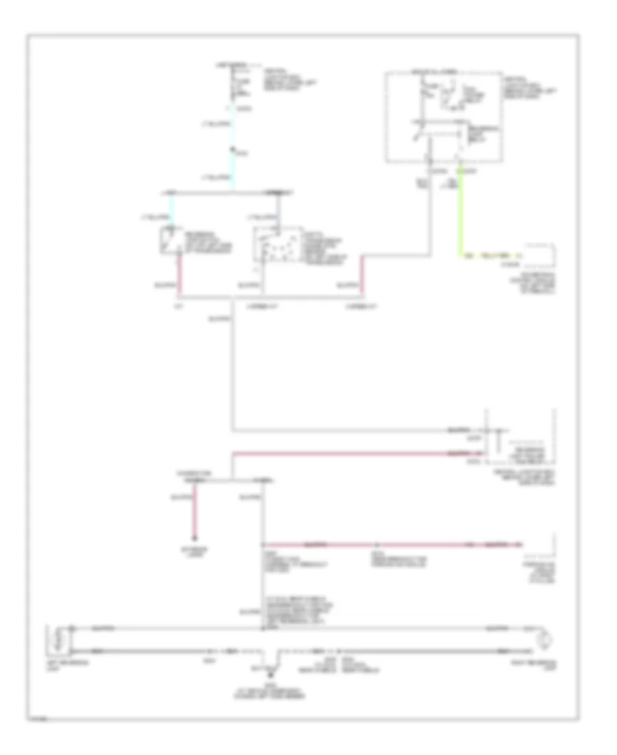
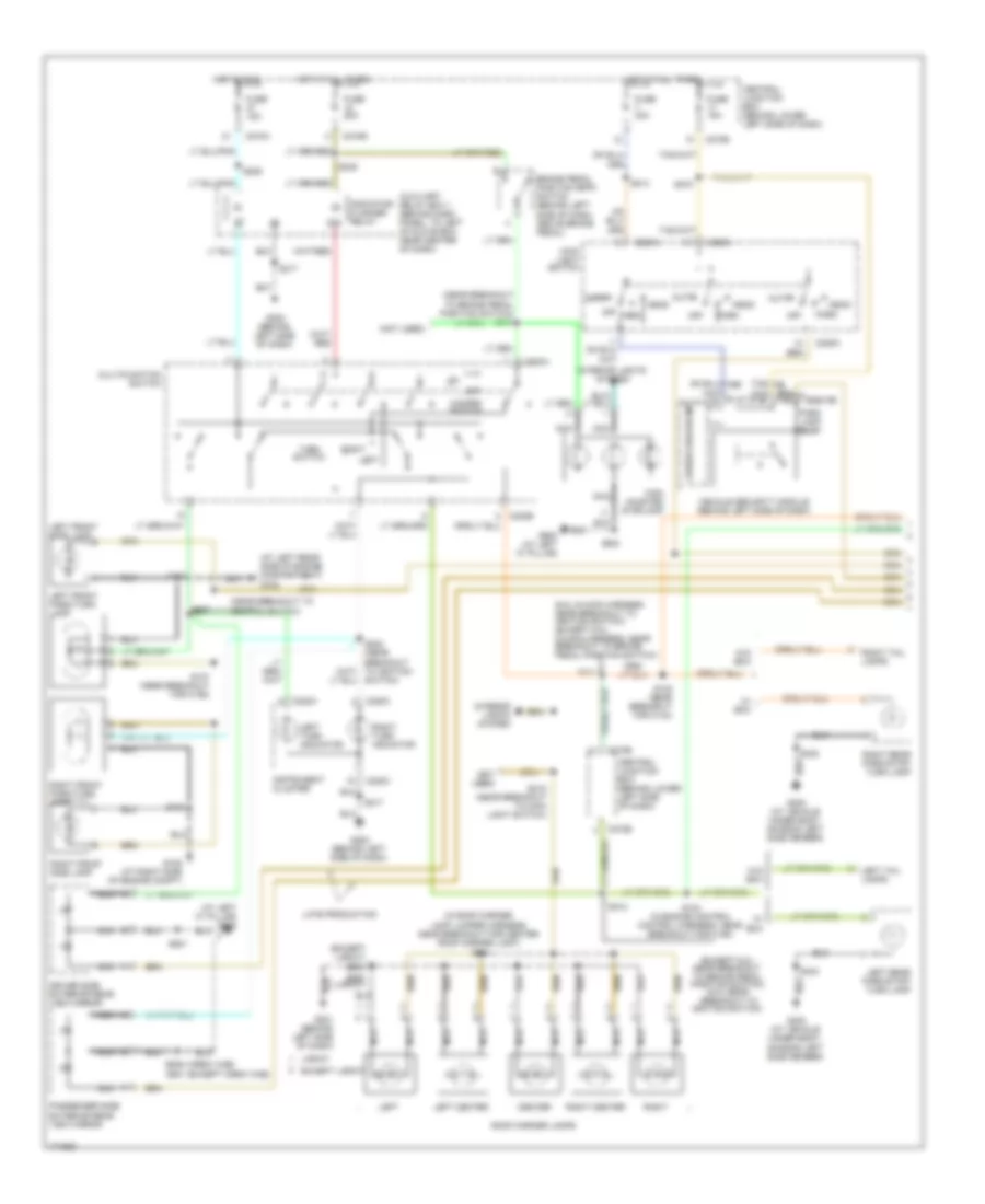
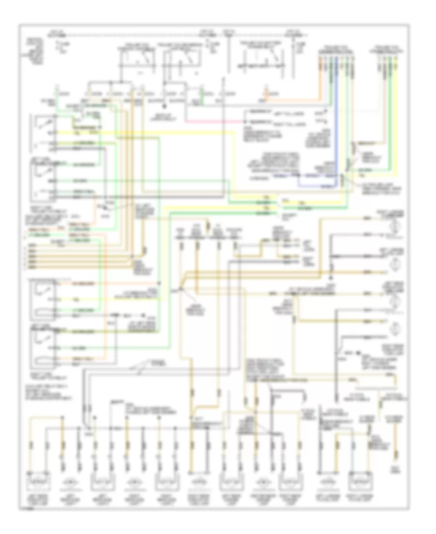
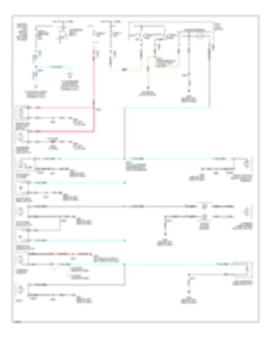
EXTERIOR LIGHTS Back-up Lamps Wiring Diagram for Ford Cab & Chassis F350 Super Duty 2003 List of elements for Back-up Lamps Wiring Diagram for Ford Cab & Chassis F350 Super Duty 2003: 33 (w/o dual rear wheels) 4 speed a/t 5 speed a/t C1381b C270f C270g C270h C270j Central junction box (behind lower left side of dash) Chassis cab, Digital transmission range (dtr) sensor (on left side of transmission) Exterior lamps Fuse 15a G400 (at vehicle under body, chassis left side member) Hot at all times Hot in run Left reversing lamp M/t Near breakout for left reversing light) s426 Parking aid module (at right ``a" pillar) Pcm power relay Powertrain control module (on left side of firewall) Reversing lamp relay Reversing lamp switch (on top left side of transmission) Reversing lamp trailer tow relay Right reversing lamp S124 S319 (near breakout for parking aid module) S357 (in body main harness, at breakout for c300) S404 S404 s402 (w/ dual rear wheels) W/ box W/o box Exterior Lamps Wiring Diagram (1 of 2) for Ford Cab & Chassis F350 Super Duty 2003 List of elements for Exterior Lamps Wiring Diagram (1 of 2) for Ford Cab & Chassis F350 Super Duty 2003: 92 (6.0l:in main harness near breakout to ignition switch) (except 6.0l: in main harness, near breakout to brake pedal position switch) (at left "c" pillar) g900 (at left rear side of engine compartment) g100 (crew cab) (except 6.0l: near breakout to brake pedal position switch) (6.0l:near breakout to ignition switch) (except crew cab) (except lariat) s904 (in roof marker lamp jumper harness, near breakout for center roof marker light) s921 (near breakout to brake pedal position switch) s240 (near breakout to ignition switch) (not used) Auto Auxiliary relay box 1 (behind dash panel, to left of glove box near center of dash) Brake pedal position (bpp) switch (behind left side of dash, above brake pedal) C202a C202b C205a C2113b C220a C220c C270a C270b Center Central junction box (behind lower left side of dash) Driver side exterior rear view mirror Except lariat Fuse 15a Fuse 20a Fuse 30a G108 (at right side of engine compt) G201 (behind left side of dash) G202 (behind left side of dash) G400 (at vehicle under body, chassis left side member) G900 (at left "c" pillar) Hazard switch Head High mounted stoplamp Hot at all times Hot in run Indicator flasher relay 87a Instrument cluster Interior lights system Lariat Late production Left Left center Left front park/turn lamp Left front side lamp Left rear park/stop/ turn lamp Left tail lamps Left turn indicator Main light switch Microprocessor Multifunction switch Nca Off Park Park lamp relay Passenger side exterior rear view mirror Right Right center Right front park/turn lamp Right front side lamp Right rear park/stop/ turn lamp Right tail lamps Right turn indicator Roof marker lamps S102 S104 (in engine control control harness, near breakout for c192) S105 (near breakout for c144) S107 (near breakout for c192) S180 S206 S207 S211 S212 S214 S215 (near breakout to main light switch) S217 S249 S272 S300 S402 S404 S501 S639 S920 (lariat) Switch) Turn switch Vehicle security module (behind left side of dash) W/ box W/o box Exterior Lamps Wiring Diagram (2 of 2) for Ford Cab & Chassis F350 Super Duty 2003 List of elements for Exterior Lamps Wiring Diagram (2 of 2) for Ford Cab & Chassis F350 Super Duty 2003: 76 (6.0l) (at left rear side of engine compartment) (at left rear side of engine compt) (f450 pickup w/box: near breakout for left license plate light) (except f450 pickup w/box: (f450 pickup w/box: near breakout for right rear park/ stop/turn light) (except f450 pickup w/box: near breakout for c438) (in trailer lamp feed harness, near breakout for c410) (near breakout for c408) (near breakout for c410) (near breakout for c410) s434 (near breakout for c465) (not used) (wire end) 6.0l Auxiliary relay box 4 (except 6.0l) (at left rear side of engine compartment) Auxiliary relay box 5 (at left rear side of engine compt) Back-up lamps circuit C270b C270f C270h C270j C270k Center rear marker lamp Central junction box (behind lower left side of dash) Except 6.0l F450 w/ box Fuse 20a G100 G400 (at vehicle under body, chassis left side member) Hot at all times Hot in run Left license plate lamp Left rear marker lamp Left rear park/stop/ turn lamp Left rear side lamp 1 Left rear side lamp 2 Left tail lamps Left turn trailer tow relay Nca Near breakout for g400) s406 Pickup w/o box Pickups w/o box Right license plate lamp Right rear marker lamp Right rear park/stop/ turn lamp Right rear side lamp 1 Right rear side lamp 2 Right tail lamps Right turn trailer tow relay S103 S103 (at breakout for auxiliary relay box 4) S162 S265 (near breakout for g300) S401 S402 S404 S407 S417 S417 (near breakout for c408) S418 (near breakout for c465) S426 (near breakout to emergency flasher relay block) S430 S431 S432 S433 S460 (in rear window defrost harness) S461 S463 Trailer tow battery charge relay Trailer tow connector (4 pin) Trailer tow connector (7 pin) Trailer tow parking lamp relay Trailer tow reversing lamp relay W/ dual rear wheels W/ rear bumper W/o dual rear wheels W/o rear bumper
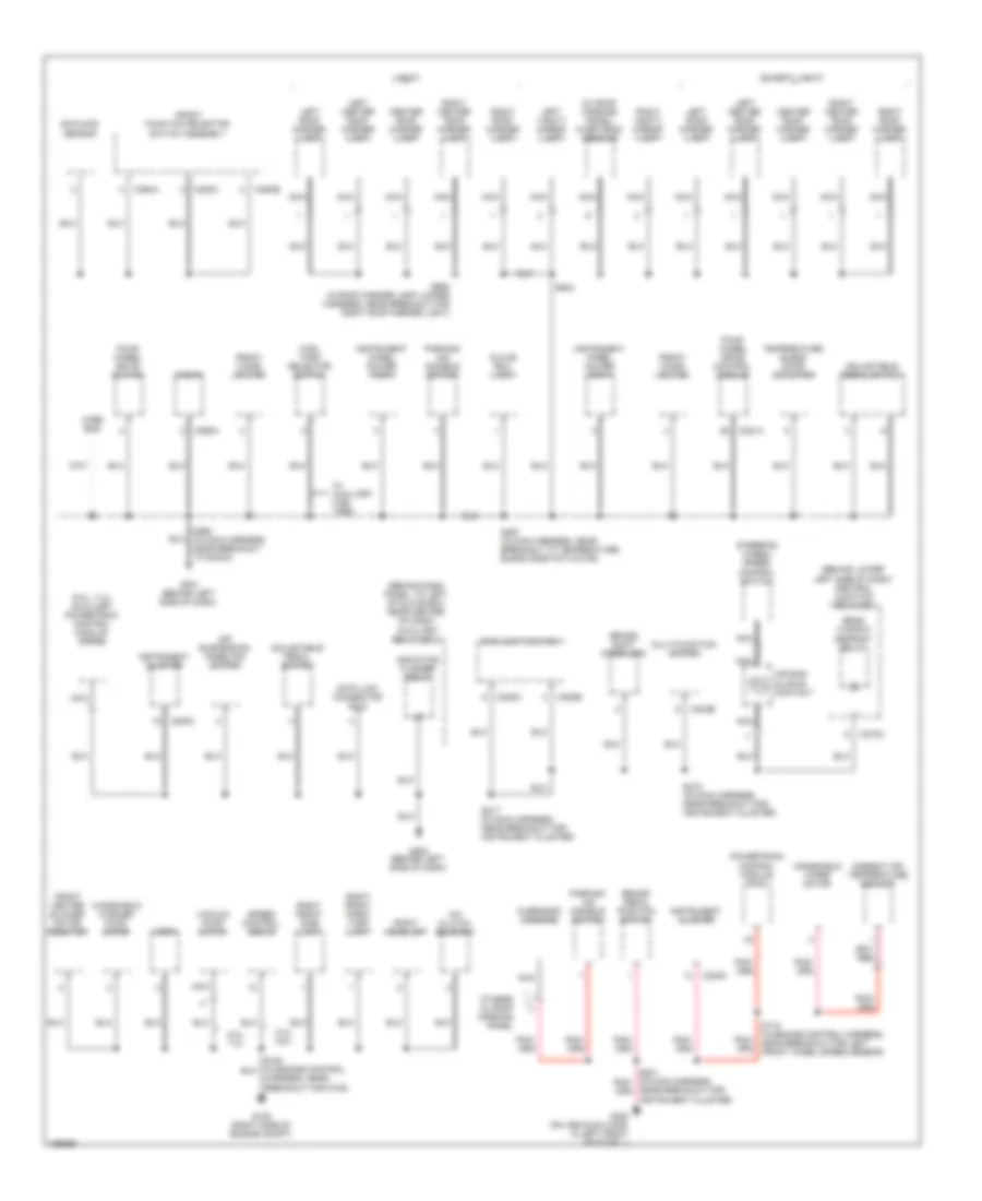
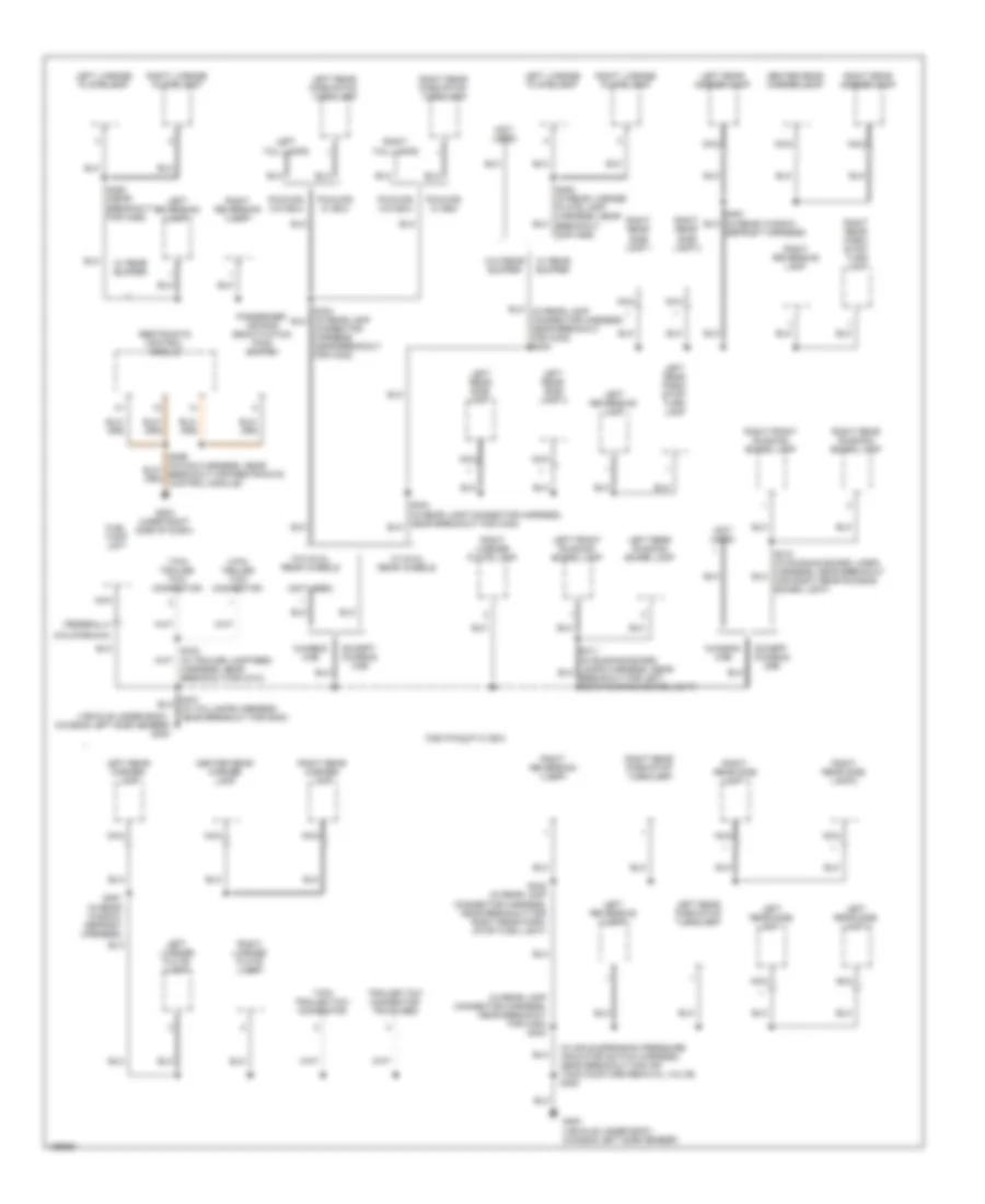
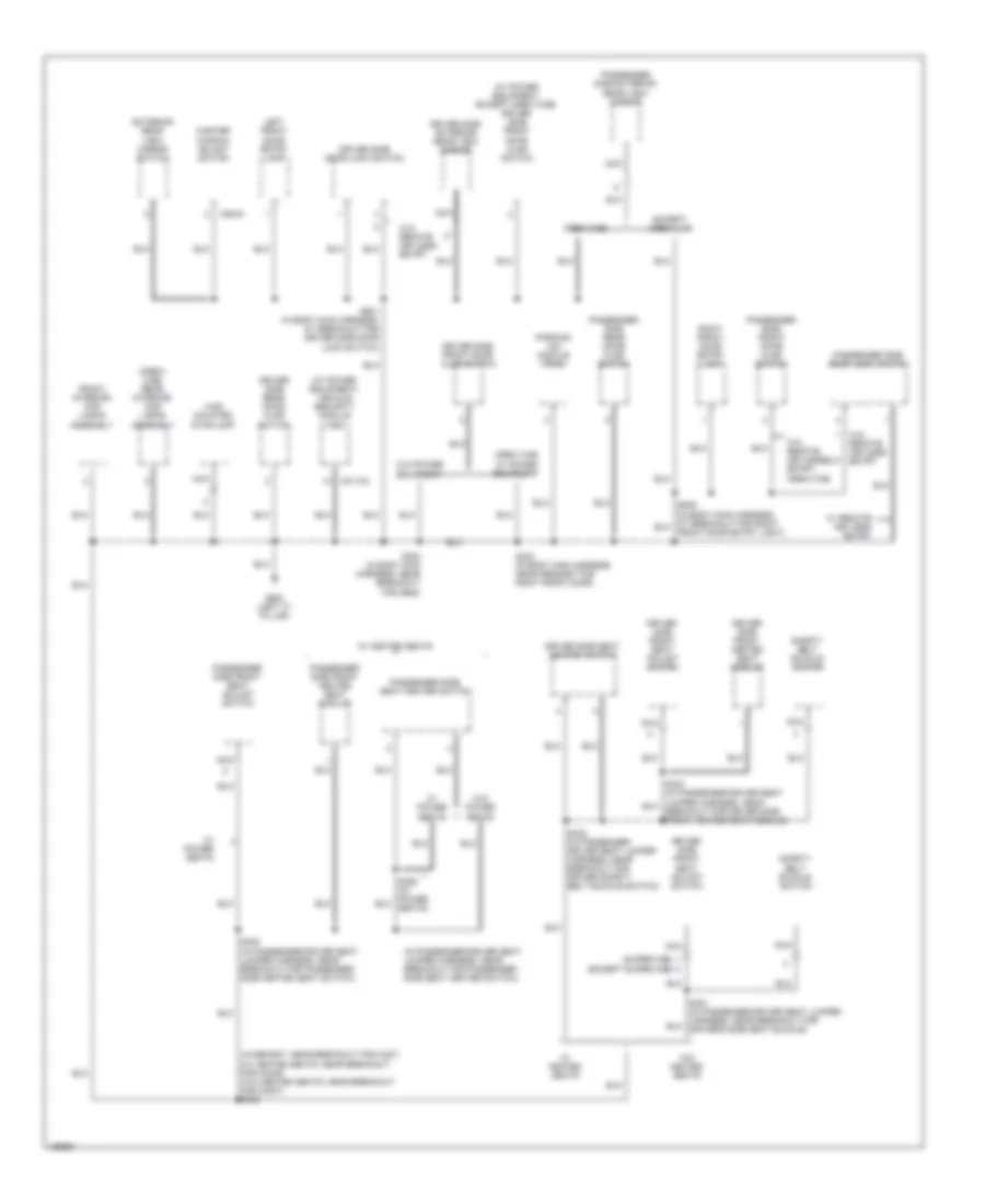
GROUND DISTRIBUTION Ground Distribution Wiring Diagram (1 of 4) for Ford Cab & Chassis F350 Super Duty 2003 List of elements for Ground Distribution Wiring Diagram (1 of 4) for Ford Cab & Chassis F350 Super Duty 2003: 85 (6.0l) (6.0l) a/c clutch solenoid (6.0l) dual pressure switch (6.0l) fuel heater (6.0l) fuel heater relay (6.0l) injector driver module (idm) (6.0l) powertrain control module (pcm) (7.3l) injector driver module (idm) (a/t: at breakout for c1010) (behind lower left side of dash) central junction box (cjb) (diesel) exhaust pressure regulator (epr) (exc 6.0l) (exc 6.0l) powertrain control module (pcm) (exc 7.3l) mass air flow (maf) sensor (left rear side of engine compartment) auxiliary relay box 2 (left rear side of engine compartment) auxiliary relay box 3 (left rear side of engine compt) (6.0l) auxiliary relay box 5 (left rear side of engine compt) (except 6.0l) auxiliary relay box 4 (m/t: at breakout for left auxiliary relay box no.3) (near breakout for injector driver module) 5.4l, 6.8l 5.4l, 6.8l, 7.3l 6.0l 7.3l 87a A/c compressor clutch diode Abs control module Air filter sensor Air suspension compressor assembly Air suspension module Air tank moisture removal valve Air tank valve Battery Battery 2 Battery charge trailer tow relay Brake fluid level switch C1381a C1388c C270f C270h C290a Control harness, near breakout for left headlight) Crankshaft position shield Data link connector (dlc) Daytime running lamps (drl) relay 1 Daytime running lamps (drl) relay 2 Engine compartment lamp Fuel pump G100 (left rear side of engine compt) G101 (left side of eng compt) G102 (right side of engine) G104 (in engine compt, at right fender) G105 (left front side of engine compt) G106 (right frame rail, in engine compt) G109 (left side of engine) G200 (behind left side of dash) Left front fog lamp Left front park/ turn lamp Left front side lamp Left headlamp Left rear shock absorber solenoid valve Left turn trailer tow relay Nca Near breakout for g100) Parking lamp trailer tow relay Pcm power diode Pcm power relay Powertrain control module (pcm) Radio Reversing lamp trailer tow relay Right front fog lamp Right rear shock absorber solenoid valve Right turn trailer tow relay S102 (in engine control harness, near breakout for g101) S106 (in engine control harness, near breakout for powertrain control module) S145 (near breakout for c110) S161 (near breakout for c110) S167 S195 S250 S380 (in air suspension pressure indicator switch harness, near breakout for air tank moisture removal valve) Starter relay Transfer case high to low Transfer case low to high Windshield wiper motor Ground Distribution Wiring Diagram (2 of 4) for Ford Cab & Chassis F350 Super Duty 2003 List of elements for Ground Distribution Wiring Diagram (2 of 4) for Ford Cab & Chassis F350 Super Duty 2003: 78 (6.0l, 7.3l) auxiliary powertrain control module (apcm) (behind dash panel, to left of glove box near center of dash) auxiliary relay box 1 (behind lower left side of dash) central junction box (cjb) (w/ roof opening panel) over head console 5.4l, 6.8l 6.0l, 7.3l A/c clutch solenoid Adjustable pedal switch Air bag sliding contact Air suspension kneeling switch Ambient air temperature sensor Brake pedal position switch Brake shift interlock C202b C205a C205b C220c C270a C281a C290a C294a C294b C294c Center roof marker lamp Data link connector (dlc) Except lariat Four- wheel drive control module Four- wheel drive switch Front cigar lighter Front function selector switch assembly Front heater blower motor resistor Fuel tank selector switch G108 (right side of engine compt) G201 (behind left side of dash) G202 (behind left side of dash) G300 (on vehicle floor, in left front footwell) Glove box lamp Harness, near breakout for g108) Horn Indicator flasher relay Instrument cluster Instrument panel power point Lariat Left center roof marker lamp Left roof marker lamp Left vanity mirror lamp Main light switch Multi-function switch Nca Near breakout for instrument cluster) Others w/ roof opening panel Overhead console Parking aid disable switch Powertrain control module (pcm) Radio Rear window defrost relay Right center roof marker lamp Right front park/ turn lamp Right front side lamp Right headlamp Right roof marker lamp Right vanity mirror lamp S172 (in engine control harness, near breakout for left front wheel speed sensor) S217 (in main harness, near breakout for instrument cluster) S218 (in main harness, near breakout for instrument cluster) S257 (in main harness, near breakout to temperature blend door actuator) S290 (in main harness, near breakout to radio) S904 S920 (in roof marker lamp jumper harness, near breakout for right roof marker light) Speed control servo Steering wheel/ speed control switch Sunload sensor Temperature blend door actuator Vacuum pump motor W/ auxiliary fuel tank Windshield washer pump motor Windshield wiper motor Wire end Ground Distribution Wiring Diagram (3 of 4) for Ford Cab & Chassis F350 Super Duty 2003 List of elements for Ground Distribution Wiring Diagram (3 of 4) for Ford Cab & Chassis F350 Super Duty 2003: 54 (california) (federal) (in air suspension pressure indicator switch harness, near breakout for air tank moisture removal valve) s380 (in rear lamp connector harness, near breakout for c408) s404 (not used) (vehicle under body, chassis left side member) g400 4-pin trailer tow connector 7-pin trailer tow connector Center rear marker lamp Chassis cab Connector harness, near breakout for c408) Defrost harness) Except chassis cab F450 pickup w/ box Fuel tank unit G203 (uner right side of dash) G400 (vehicle under body, chassis left side member) Harness, near breakout for c410) Left front running board lamp Left license plate lamp Left rear marker lamp Left rear park/ stop/ turn lamp Left rear park/stop turn lamp Left rear park/stop/ turn lamp Left rear running board lamp Left rear side lamp 1 Left rear side lamp 2 Left reversing lamp Left tail lamps Nca Passenger air bag deactivation (pad) switch Pickups w/ box Pickups w/o box Restraints control module Right front running board lamp Right license plate lamp Right rear marker lamp Right rear park/ stop/ turn lamp Right rear park/stop turn lamp Right rear park/stop/ turn lamp Right rear running board lamp Right rear side lamp 1 Right rear side lamp 2 Right reversing lamp Right tail lamps S402 (in rear lamp connector harness, near breakout for right rear park/ stop/turn light) S461 (in rear window defrost harness) S463 (in rear license plate lamp harness, near breakout for c465) S463 (near breakout for c465) Trailer tow connector truck bed W/ dual rear wheels W/ rear bumper W/o dual rear wheels W/o rear bumper Ground Distribution Wiring Diagram (4 of 4) for Ford Cab & Chassis F350 Super Duty 2003 List of elements for Ground Distribution Wiring Diagram (4 of 4) for Ford Cab & Chassis F350 Super Duty 2003: 49 (crew cab) rear interior/ map lamps assembly (except super cab) (in passenger-driver seat jumper harness, near breakout for passenger side seat heater switch) (super cab) (w/ power equipment) vehicle security module (vsm) (w/ power equipment, except crew cab) driver side front door ajar switch (w/memory: near breakout for c327) (w/ heated seats: near breakout for c3049) (w/o heated seats: near breakout for c3007) s306 C2113a C504a Crew cab Driver side door lock switch Driver side exterior rear view mirror Driver side front door ajar switch Driver side front heated seat module Driver side front seat adjust switch Driver side rear door ajar switch Driver side seat heater switch Except crew cab Exterior rear view mirror switch Front interior/ map lamps assembly G900 (left "c" pillar) High mounted stoplamp Left front door entry lamp Master window adjust switch Nca Parking aid module (pam) Passenger side door lock switch Passenger side exterior rear view mirror Passenger side front door ajar switch Passenger side front heated seat module Passenger side front seat adjust switch Passenger side rear door ajar switch Passenger side seat heater switch Right front door entry lamp S233 (in body main harness, near grommet for right front door) S300 (in body main harness, near breakout for g900) S332 (in passenger- driver seat jumper harness, near breakout for driver safety belt buckle switch) S335 (in passenger-driver seat jumper harness, near breakout for passenger side heated seat switch) S501 (in body main harness, at breakout for driver side door lock switch) Safety belt buckle switch W/ heated seats W/ power equipment W/ power seats W/ remote keyless entry W/o heated seats W/o power equipment W/o power seats W/o remote keyless entry W/o remote keyless entry, crew cab
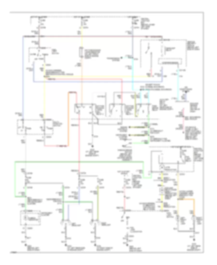
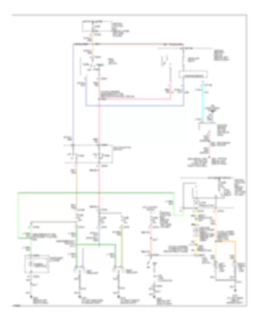
HEADLIGHTS Headlights Wiring Diagram, with DRL for Ford Cab & Chassis F350 Super Duty 2003 List of elements for Headlights Wiring Diagram, with DRL for Ford Cab & Chassis F350 Super Duty 2003: 79 (early production) s221 (except pickup & diesel excursion) (excursion) (pickup) (in fog jumper harness, near breakout for c1045) s100 (in main harness, at breakout for foglamp relay diode) (in main harness, near breakout for restraints control module) s244 (late (near breakout for g100) (on vehicle floor, in left front footwell) g300 g201 (behind left side of dash) (pickup & diesel excursion) 87a Air conditioning system Auto Auxiliary relay box 2 (at left rear side of engine compt) C202a C205a C2113b C220c C270a C270b C270f C270g C270h Central junction box (behind lower left side of dash) Central junction box (behind lower left side of dash) Daytime running lamps (drl) relay 1 Daytime running lamps (drl) relay 2 Daytime running lamps resistor (on left front side of engine compt) Diesel Engine controls system Fog Fog lamp illumination Fog lamp relay Foglamp relay diode (early production) (behind left side of dash) For c1047) Fuse 10a Fuse 15a Fuse 30a G100 (at left rear side of engine compt) G108 (at right side of engine compt) G202 (behind left side of dash) Head Headlamp relay Hi-beam indicator Hot at all times Hot in run Hot in start or run Hot in start or run Instrument cluster Instrument cluster system Left front fog lamp Left headlamp Main light switch Microprocessor Multi- function switch Off Park Park brake relay Parking brake switch (behind left side of dash, (on park brake assembly) Pass Production) Right front fog lamp Right headlamp S101 S102 S113 S124 S180 S198 S201 s290 S203 (near breakout for instrument cluster) S214 S217 S220 (early production) S271 Sunload sensor (on top center of dash) Tan/ Transmission system Vehicle security module (behind left side of dash) Headlights Wiring Diagram, without DRL for Ford Cab & Chassis F350 Super Duty 2003 List of elements for Headlights Wiring Diagram, without DRL for Ford Cab & Chassis F350 Super Duty 2003: 64 (early production) s221 (excursion) (excursion) (pickup) (in fog jumper harness, near breakout for c1045) s100 (in main harness, at breakout for foglamp relay diode) (in main harness, near breakout for restraints control module) (late (near breakout for g100) (pickup) Air conditioning system Auto C202a C205a C2113b C220c C270a C270b C270f C270g C270h Central junction box (behind lower left side of dash) Central junction box (behind lower left side of dash) Fog Fog lamp illumination Fog lamp relay Foglamp relay diode (early production) (behind left side of dash) Fuse 10a Fuse 15a Fuse 30a G100 (at left rear side of engine compt) G108 (at right side of engine compt) G201 (behind left side of dash) G202 (behind left side of dash) G300 (on vehicle floor, in left front footwell) Head Headlamp relay Hi-beam indicator Hot at all times Hot in start or run Instrument cluster Left front fog lamp Left headlamp Main light switch Microprocessor Multi-function switch Off Park Pass Production) Right front fog lamp Right headlamp S101 S102 S113 S180 S201 s290 S214 S217 S220 (early production) S244 S271 Sunload sensor (on top center of dash) Tan/ Vehicle security module (behind left side of dash)
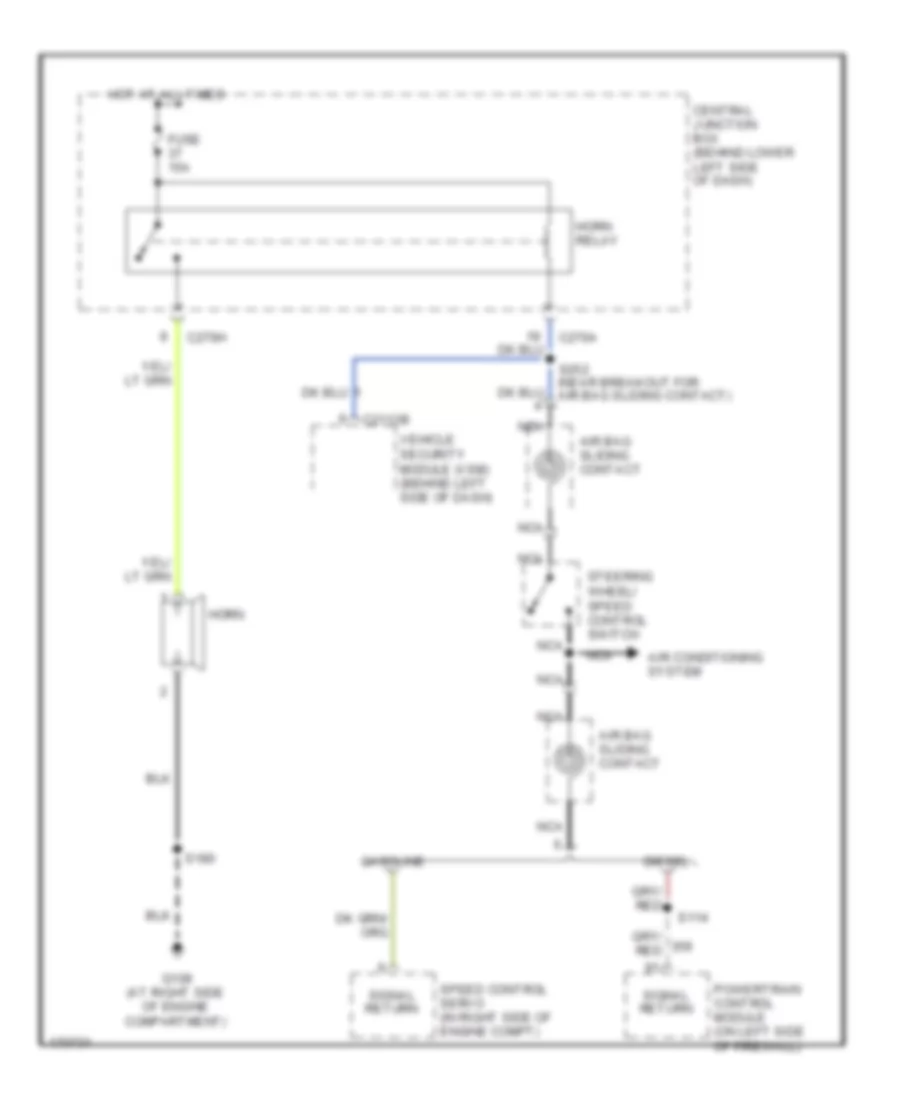
HORN Horn Wiring Diagram for Ford Cab & Chassis F350 Super Duty 2003 List of elements for Horn Wiring Diagram for Ford Cab & Chassis F350 Super Duty 2003: 22 Air bag sliding contact Air conditioning system C2113b C270a C270h Central junction box (behind lower left side of dash) Diesel Fuse 15a G108 (at right side of engine compartment) Gasoline Horn Horn relay Hot at all times Nca Powertrain control module (on left side of firewall) S114 S180 S252 (near breakout for air bag sliding contact) Signal return Speed control servo (in right side of engine compt) Steering wheel/ speed control switch Vehicle security module (vsm) (behind left side of dash)
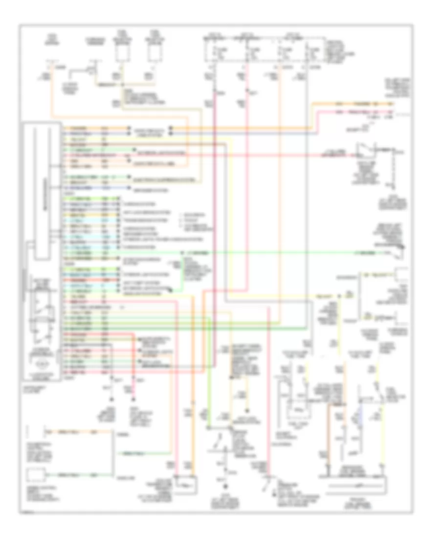
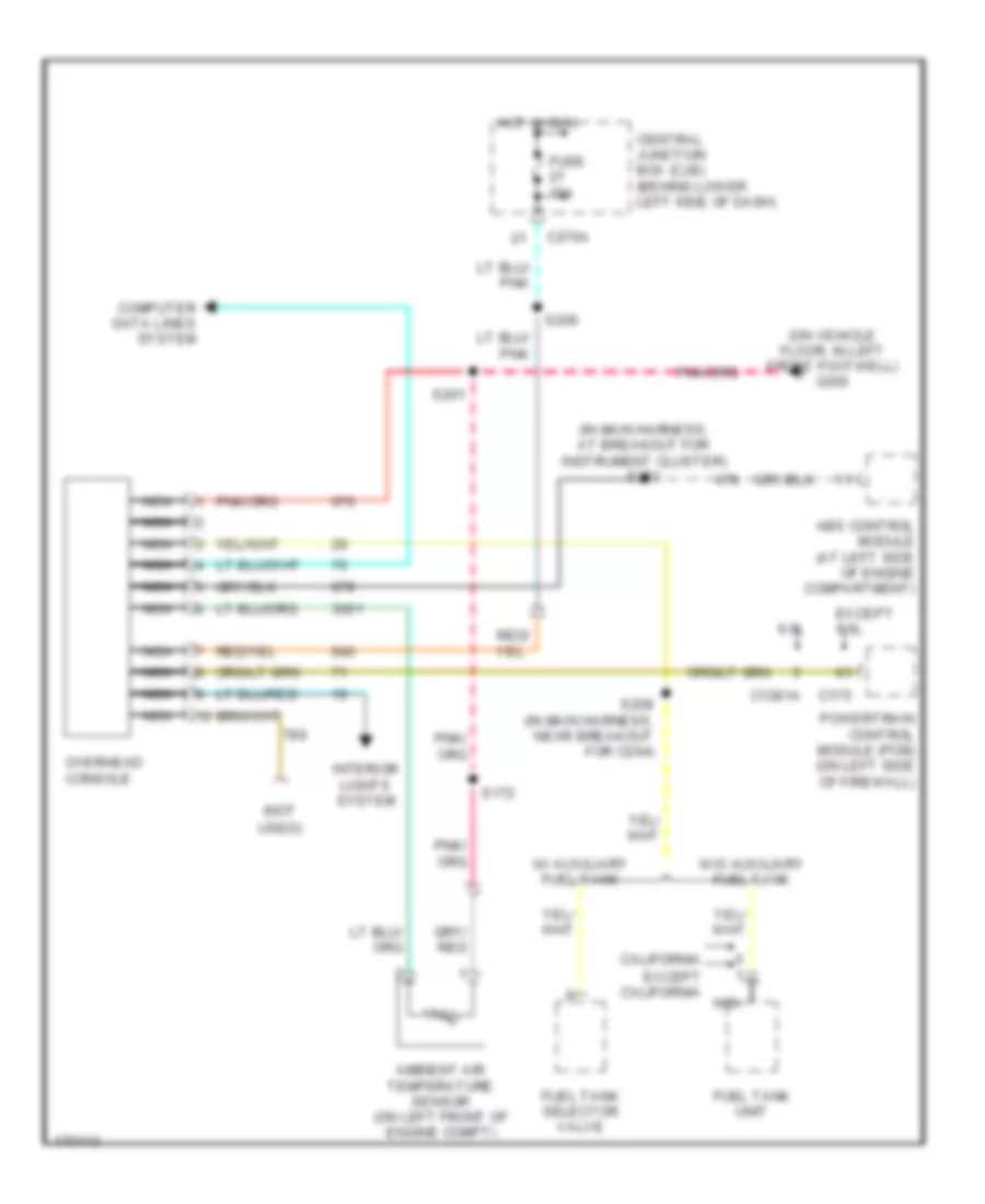
INSTRUMENT CLUSTER Instrument Cluster Wiring Diagram for Ford Cab & Chassis F350 Super Duty 2003 List of elements for Instrument Cluster Wiring Diagram for Ford Cab & Chassis F350 Super Duty 2003: 74 (behind left side of dash, on park brake assembly) parking brake switch (in taillamps harness, near breakout for fuel tank selector valve) s400 (on left side of firewall) powertrain control module (pcm) 6.0l except 6.0l Air filter sensor (diesel) (on left side of engine compartment) Anti-lock brake system Anti-theft system Battery saver relay Brake fluid level switch (on brake fluid reservoir) C1381a C175 C205b C220a C220b C220c C270a C270b California Central junction box (cjb) (behind lower left side of dash) Computer data lines Computer data lines system Coolant temperature sensor 2 (diesel) (at top of engine, on water pump) Defogger system Diesel Electronic suspension system Except california Excursion Exterior lights system Fuel tank selector switch Fuel tank selector valve Fuel tank unit Fuse 10a Fuse 15a G100 (at left rear side of engine compartment) G202 (behind left side of dash) G300 (on vehicle floor, in left front footwell) Gasoline Headlights system Hot at all times Hot in run or acc Hot in start or run Illumination (6 bulbs) Instrument cluster Interior lamps relay Interior lights system Interior lights, power windows system Keyless entry Main light switch Microprocessor Nca Oil pressure switch (5.4l, 6.8l: on left front of engine) (7.3l: on top center rear of engine) Overhead console Pickup Powertrain control module (pcm) (on left side of firewall) Primary fuel sender (on fuel tank) S102 S201 S208 (in main harness, near breakout for c264) S217 S254 S271 S278 (in main harness, at breakout for instrument cluster) S298 (in main harness, at breakout for instrument cluster) Secondary fuel sender (on fuel tank) Speed control servo (in right side of engine compt) Starting/charging system Transmissions system Trip computer module (on front center of roof) W/ auxiliary fuel tank W/ roof opening panel W/o auxiliary fuel tank W/o remote W/o roof opening panel Warning system Overhead Console Wiring Diagram, with Roof Opening Panel for Ford Cab & Chassis F350 Super Duty 2003 List of elements for Overhead Console Wiring Diagram, with Roof Opening Panel for Ford Cab & Chassis F350 Super Duty 2003: 29 (in main harness, at breakout for instrument cluster) s253 (not (on vehicle floor, in left front footwell) g300 6.0l Abs control module (at left side of engine compartment) Ambient air temperature sensor (on left front of engine compt) C1381a C175 C270a California Central junction box (cjb) (behind lower left side of dash) Computer data lines system Except 6.0l Except california Fuel tank selector valve Fuel tank unit Fuse 15a Hot in run Interior lights system Nca Overhead console Powertrain control module (pcm) (on left side of firewall) S172 S201 S206 S208 (in main harness, near breakout for c264) Used) W/ auxiliary fuel tank W/o auxiliary fuel tank Overhead Console Wiring Diagram, without Roof Opening Panel for Ford Cab & Chassis F350 Super Duty 2003 List of elements for Overhead Console Wiring Diagram, without Roof Opening Panel for Ford Cab & Chassis F350 Super Duty 2003: 29 (in main harness, at breakout for instrument cluster) s253 (not (on vehicle floor, in left front footwell) g300 6.0l Abs control module (at left side of engine compartment) Ambient air temperature sensor (on left front of engine compt) C1381a C175 C270a California Central junction box (cjb) (behind lower left side of dash) Computer data lines system Except 6.0l Except california Fuel tank selector valve Fuel tank unit Fuse 15a Hot in run Interior lights system Nca Overhead console Powertrain control module (pcm) (on left side of firewall) S172 S201 S206 S208 (in main harness, near breakout for c264) Used) W/ auxiliary fuel tank W/o auxiliary fuel tank
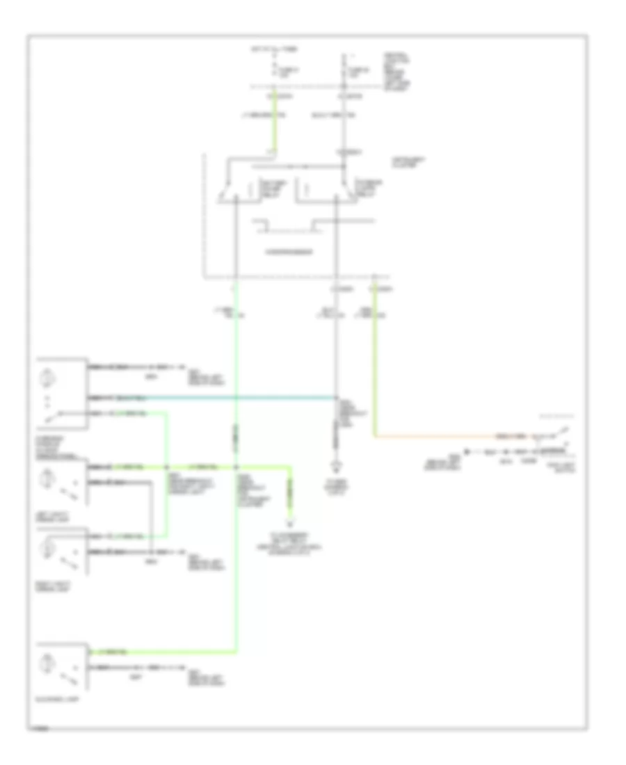
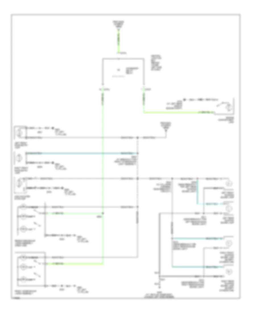
INTERIOR LIGHTS Courtesy Lamps Wiring Diagram (1 of 2) for Ford Cab & Chassis F350 Super Duty 2003 List of elements for Courtesy Lamps Wiring Diagram (1 of 2) for Ford Cab & Chassis F350 Super Duty 2003: 30 Battery saver relay C205b C220a C220c C270a C270b Central junction box (behind lower left side of dash) Fuse 35 10a Fuse 41 10a G201 (behind left side of dash) G202 (behind left side of dash) Glove box lamp Hot at all times Instrument cluster Interior Interior lamps relay Left vanity mirror lamp Main light switch Microprocessor Nca Overhead console (w/ roof opening panel) Right vanity mirror lamp S204 (near breakout for c264) S218 S229 (near breakout for instrument cluster) S257 S904 S937 (near breakout for right vanity mirror light) To accessory delay relay (central junction box) (diagram 2 of 2) To s905 (diagram 2 of 2) Courtesy Lamps Wiring Diagram (2 of 2) for Ford Cab & Chassis F350 Super Duty 2003 List of elements for Courtesy Lamps Wiring Diagram (2 of 2) for Ford Cab & Chassis F350 Super Duty 2003: 35 Accessory delay relay C270a C270f C270j Central junction box (behind lower left side of dash) Engine compartment lamp From s204 (diagram 1 of 2) From s229 (diagram 1 of 2) Front interior/map lamps assembly G100 (at left rear side of engine compt) G400 (at vehicle under body, chassis left side member) G900 (at left ``c" pillar) High mounted stoplamp Interior Left front door entry lamp Left front running board lamp Left rear running board lamp Map Nca Rear interior/map lamps assembly (crew cab) Right front door entry lamp Right front running board lamp (except chassis cab) Right rear running board lamp (except chassis cab) S162 S300 S309 (near breakout for left rear running board light) S310 (near breakout for right rear running board light) S311 (near breakout for left rear running board light) S312 (near breakout for right rear running board light) S344 (in taillamps harness, near breakout for c311) S401 S501 S639 S905 (at breakout for front interior/map light assembly) S906 Instrument Illumination Wiring Diagram (1 of 2) for Ford Cab & Chassis F350 Super Duty 2003 List of elements for Instrument Illumination Wiring Diagram (1 of 2) for Ford Cab & Chassis F350 Super Duty 2003: 57 (w/ roof opening panel) (w/o rke) s639 (w/o roof Accessory delay relay Adjustable pedal switch Air bag sliding contact Air suspension kneeling switch Auto Bulbs C205a C205b C220c C270b C270i C270j C290a C294b Central junction box (behind lower left side of dash) Circuit breaker 30a Driver side door lock switch Exterior lights system Four-wheel drive switch Front function selector switch assembly Fuse 17 15a Fuse 42 15a G201 (behind left side of dash) G202 (behind left side of dash) G300 (on vehicle floor, in left front footwell) G900 (at left ``c" pillar) Head Hot at all times Instrument cluster Main light switch Microprocessor Nca Off Opening panel) Overhead console Park Parking aid disable switch Passenger side door lock switch Pnk Radio S201 S215 (near breakout to main light switch) S216 (in main harness, near breakout sunload sensor) S217 S218 S233 (w/ rke) S272 S290 S297 S302 S501 Steering wheel/speed control switch To master window adjust switch (diagram 2 of 2) To passenger side window adjust switch (diagram 2 of 2) Instrument Illumination Wiring Diagram (2 of 2) for Ford Cab & Chassis F350 Super Duty 2003 List of elements for Instrument Illumination Wiring Diagram (2 of 2) for Ford Cab & Chassis F350 Super Duty 2003: 12 C504a C504b Crew cab Except crew cab From s297 (diagram 1 of 2) G900 (at left ``c" pillar) Left rear window adjust switch Master window adjust switch Passenger side window adjust switch Right rear window adjust switch S328 (near breakout for g300) S501
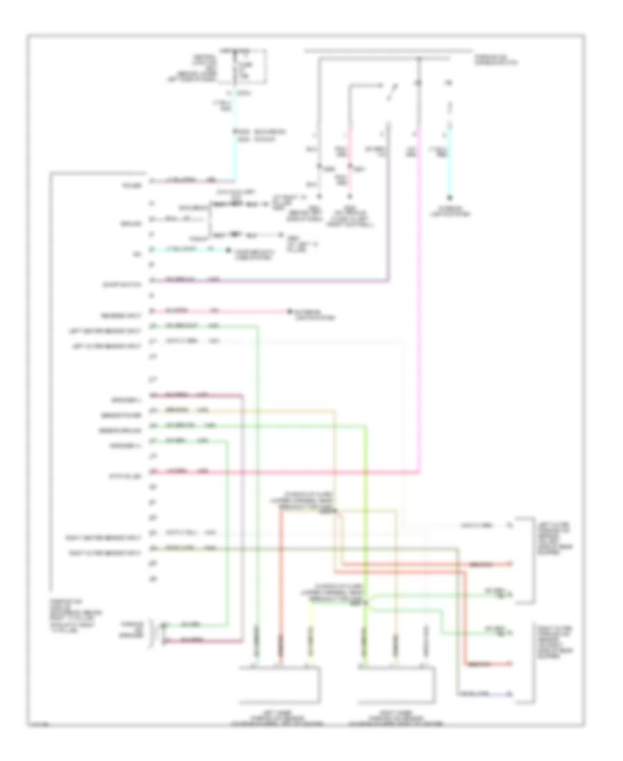
NAVIGATION Navigation Wiring Diagram for Ford Cab & Chassis F350 Super Duty 2003 List of elements for Navigation Wiring Diagram for Ford Cab & Chassis F350 Super Duty 2003: 47 (at right ``d" pillar) g403 (behind left side of dash) (excursion) (in back-up alarm jumper harness, near breakout for c406) (pickup) (pickup:at right ``a" pillar) (w/o auxiliary a/c) s323 C270j Central junction box (behind lower left side of dash) Compuer data lines system Excursion Exterior lights system Fuse 15a G201 G300 (on vehicle floor, in left front footwell) G900 (at left ``c" pillar) Ground Hot in run Interior lights system Iso Left center sensor input Left inner parking aid sensor (on rear bumper, left of center) Left outer parking aid sensor (on left side of rear bumper) Left outer sensor input On/off switch Parking aid disable switch Parking aid module (excursion: behind right ``c" pillar) Parking aid speaker Pickup Power Reverse input Right center sensor input Right inner parking aid sensor (on rear bumper, right of center) Right outer parking aid sensor (on right side of rear bumper) Right outer sensor input S201 S233 S290 S303 S320 S450 S451 Sensor ground Sensor power Speaker (+) Speaker (-) Status led
POWER DISTRIBUTION Power Distribution Wiring Diagram (1 of 4) for Ford Cab & Chassis F350 Super Duty 2003 List of elements for Power Distribution Wiring Diagram (1 of 4) for Ford Cab & Chassis F350 Super Duty 2003: 98 (6.0l) (except 6.0l) (behind left side of dash) g201 (breakout for auxiliary relay box 4) s103 (except 6.0l) (6.0l) (in back-up light switch to rear light feed harness, at breakout for auxiliary relay box 3) s199 (in engine control harness, near breakout for abs control module) s163 (near breakout for auxiliary relay box 1) s249 (near breakout for data link connector) s242 (near breakout for instrument cluster) s228 (near breakout for instrument cluster) s275 (near breakout to brake pedal position switch) s214 (near breakout to main light switch) s272 5 speed a/t 6.0l A/c clutch relay Abs control module Adjustable pedal switch Auxiliary relay box 1 (behind dash panel, to left of glove box near center of dash) Auxiliary relay box 3 (left rear side of engine compt) Auxiliary relay box 4 (except 6.0l) auxiliary relay box 5 (6.0l) (left rear side of engine compt) Auxiliary relay box 4 (or 5) (left rear side of engine compt) Auxiliary relay box 5 (left rear side of engine compt) Battery Battery ii (6.0l/7.3l) Brake pedal position switch Brake pressure switch (5.4l/6.8l) C202a C205a C2113b C270a C270b C270d C270e C270f C270g C270h C270i C270j C270k C270m C270p C281c C290a Central junction box (cjb) (behind lower left side of dash) Clutch pedal position switch Data link connector (dlc) Daytime running lamps resistor Digital transmission range (dtr) sensor Except 5 speed a/t Except 6.0l Exterior rear view mirror switch Four- wheel drive control module Four-wheel drive control module (w/ electronic shift on the fly) From a fuse 602 (diagram 1 of 4) From b fuse 13 (diagram 1 of 4) From ignition switch (diagram 3 of 4) Front cigar lighter Fuse 1 15a Fuse 10 10a Fuse 11 20a Fuse 111 30a Fuse 114 30a Fuse 12 20a Fuse 13 10a Fuse 14 15a Fuse 17 15a Fuse 18 20a Fuse 19 5a Fuse 20 10a Fuse 31 15a Fuse 34 10a Fuse 4 20a Fuse 5a Fuse 6 20a Fuse 602 60a Fuse 7 30a Indicator flasher relay Injector driver module power relay Instrument panel power point Junction block Left turn trailer tow relay Main light switch Multi- function switch Nca Passenger side front seat adjust switch Radio Red Right turn trailer tow relay S1000 (in battery output harness, at breakout for junction block on left fender) S1002 (in battery output harness, near grommet on firewall) S257 s290 S290 s257 Starter relay To fuse (diagram 1 of 4) To fuse 35 (diagram 2 of 4) Transfer case high to low relay Transfer case low to high relay Vehicle security module (vsm) Power Distribution Wiring Diagram (2 of 4) for Ford Cab & Chassis F350 Super Duty 2003 List of elements for Power Distribution Wiring Diagram (2 of 4) for Ford Cab & Chassis F350 Super Duty 2003: 63 (6.0l) (in body main harness, near breakout for g300) s289 (in body main harness, near grommet on left side of vehicle floor) s315 (in main harness, at breakout for instrument cluster) s254 (w/ super cab) Battery charge trailer tow relay C175 C2113b C220c C270a C270b C270c C270e C270g C270i C270k C270m C281c C3181a Central junction box (cjb) (behind lower left side of dash) Driver side door lock switch Driver side front heated seat module Driver side front seat adjust switch Four-wheel drive control module From c fuse 111 (diagram 1 of 4) From d fuse 112 (diagram 2 of 4) From ignition switch (diagram 3 of 4) Fuel heater relay (6.0l) Fuel pump relay Fuel tank selector switch Fuse 101 30a Fuse 102 30a Fuse 104 40a Fuse 105 30a Fuse 106 30a Fuse 109 30a Fuse 112 30a Fuse 113 30a Fuse 115 20a Fuse 33 15a Fuse 35 10a Fuse 36 10a Fuse 37 15a Fuse 40 20a Fuse 41 10a Horn relay Injector driver module (idm) power relay (7.3l) Instrument cluster Nca Not used Passenger side door lock switch Passenger side front heated seat module Pcm power relay Powertrain control module (pcm) Rear window defrost relay Red Starter relay To fuse (diagram 2 of 4) To fuse (diagram 3 of 4) Vehicle security module (vsm) W/ remote keyless entry W/o remote keyless entry Windshield wiper motor Power Distribution Wiring Diagram (3 of 4) for Ford Cab & Chassis F350 Super Duty 2003 List of elements for Power Distribution Wiring Diagram (3 of 4) for Ford Cab & Chassis F350 Super Duty 2003: 88 (5.4l: near breakout for fuel injector 3) (6.8l: near breakout for fuel injector 5) s135 (5.4l: near breakout for fuel injector 6) (6.8l: near breakout for fuel injector 9) s130 (6.0l/7.3l) (a/t) (in engine control harness, near breakout for left headlight) (6.0l) s109 (in engine control sensor & fuel charge harness, near breakout for waste gate solenoid) s154 (in main harness, near breakout for instrument cluster) s271 (in main harness, near breakout for restraints control module) s202 (in main harness, near breakout to ignition switch) s210 (not used) (or 4 speed a/t 5 speed a/t 5.4l 5.4l/6.8l 6.0l 6.0l/7.3l 6.8l Abs control module Acc Accelerator pedal position sensor Auxiliary powertrain control module (apcm) (6.0l/7.3l) Auxiliary relay box 5 (left rear side of engine compt) Blower motor relay C1388c C220c C270a C270c C270e C270f C281a Central junction box (cjb) (behind lower left side of dash) Clutch triple function switch jumper clutch pedal position switch (m/t) Coil on plug (cop) 1 Coil on plug (cop) 10 Coil on plug (cop) 2 Coil on plug (cop) 3 Coil on plug (cop) 4 Coil on plug (cop) 5 Coil on plug (cop) 6 Coil on plug (cop) 7 Coil on plug (cop) 8 Coil on plug (cop) 9 (6.8l) Electronic fan clutch (6.0l) Except 6.0l Fog lamp relay Four- wheel drive control module From e fuse 115 (diagram 2 of 4) Fuel heater Fuel heater relay Fuse 103 50a Fuse 107 40a Fuse 10a Fuse 110 50a Fuse 116 30a Fuse 25 10a Fuse 26 10a Fuse 38 20a Fuse 45 10a Fuse 8 15a Grade/ load switch Ignition switch Ignition transformer capacitor 1 Ignition transformer capacitor 2 Injector driver module (idm) Injector driver module (idm) power relay Instrument cluster Lock Main light switch (w/ fog lamps) Nca Off Overdrive cancel switch Parking lamp trailer tow relay Passenger air bag deactivation (pad) switch Pcm power relay Restraints control module Reversing lamp trailer tow relay Reversing lamps relay Run S224 (in main harness, near breakout to brake pedal position switch) S258 (in main harness, near breakout to brake pedal position switch) Sta Start Tan/red To fuse 27 (diagram 4 of 4) To fuse 31 (diagram 1 of 4) To fuse 33 (diagram 2 of 4) Waste gate solenoid Power Distribution Wiring Diagram (4 of 4) for Ford Cab & Chassis F350 Super Duty 2003 List of elements for Power Distribution Wiring Diagram (4 of 4) for Ford Cab & Chassis F350 Super Duty 2003: 44 (in body main harness, near breakout for c340) s303 (in daytime running light kit harness, near breakout for c1047) s198 (in engine control harness, near breakout for g100) s124 (in main harness, near breakout sunload sensor) s206 (in main harness, near breakout sunload sensor) s235 (in main harness, near breakout to air suspension kneeling switch) s296 (not used) 5.4l/6.8l 6.0l/7.3l A/t Air suspension kneeling switch Air suspension module Auxiliary relay box 1 (behind dash panel, to left of glove box near center of dash) Auxiliary relay box 2 (left rear side of engine compartment) Battery charge trailer tow relay Blower motor relay Brake shift interlock C270a C270c C270h C294a Central junction box (cjb) (behind lower left side of dash) Digital transmission range (dtr) sensor Driver side front heated seat module Electronic shift on the fly (esof) solenoid From fuse 25 (diagram 3 of 4) From ignition switch (diagram 3 of 4) Front function selector switch assembly Fuse 10a Fuse 15a Fuse 27 15a Indicator flasher relay M/t Nca Overhead console Park brake relay Parking aid module (pam) Passenter side front heated seat module Rear window defrost relay Reversing lamps switch Speed control servo Temperature blend door actuator Vaccum pump motor W/ roof opening panel
POWER DOOR LOCKS Power Door Locks Wiring Diagram, without Keyless Entry for Ford Cab & Chassis F350 Super Duty 2003 List of elements for Power Door Locks Wiring Diagram, without Keyless Entry for Ford Cab & Chassis F350 Super Duty 2003: 19 (in body main harness, near breakout for c340) s304 C270e Central junction box (cjb) (behind lower left side of dash) Driver side door lock switch Fuse 30a G900 (at left ``c" pillar) Hot at all times Interior lights system Left front door lock actuator Left rear door lock actuator (w/ crew cab) Lock Passenger side door lock actuator Passenger side door lock switch Pnk Right rear door lock actuator (w/ crew cab) S289 S501 S639 Unlock
POWER MIRRORS Power Mirrors Wiring Diagram for Ford Cab & Chassis F350 Super Duty 2003 List of elements for Power Mirrors Wiring Diagram for Ford Cab & Chassis F350 Super Duty 2003: 27 (at left "c" pillar) g900 (crew cab) (except crew cab) (near breakout for g300) s279 C270d C270j Central junction box (cjb) (behind lower left side of dash) Down Driver side exterior rear view mirror Exterior lights system Exterior rear view mirror switch Fuse 10a Fuse 20a Fuse 40a G301 (at left "c" pillar) Hot at all times Left Left mirror select Nca Passenger side exterior rear view mirror Rear window defrost relay Red Right Right mirror select S317 (near grommet on left side of vehicle floor) S501 S639
POWER SEATS Adjustable Pedal Wiring Diagram for Ford Cab & Chassis F350 Super Duty 2003 List of elements for Adjustable Pedal Wiring Diagram for Ford Cab & Chassis F350 Super Duty 2003: 12 270d Adjustable pedal motor (in driver's footwell) Adjustable pedal switch Central junction box (behind lower left side of dash) Fuse 15a Fwd G201 (behind left side of dash) Hot at all times Interior lights system Nca Rwd S257 Driver Power Seat Wiring Diagram for Ford Cab & Chassis F350 Super Duty 2003 List of elements for Driver Power Seat Wiring Diagram for Ford Cab & Chassis F350 Super Duty 2003: 26 (at left "c" pillar) g301 (excursion) (excursion) (pickup) (on vehicle floor, in left front footwell) g300 (pickup) (pickup) (excursion) C270i Central junction box (behind lower left side of dash) Driver side front seat adjust switch Except super cab Forward/rearward Front up/down Fuse 30a Fwd G900 (at left "c" pillar) Hot at all times Left power seat motor assembly Nca Rear up/down Rwd S332 s301 St dn St up Super cab W/ heated seats W/o heated seats Heated Seats Wiring Diagram for Ford Cab & Chassis F350 Super Duty 2003 List of elements for Heated Seats Wiring Diagram for Ford Cab & Chassis F350 Super Duty 2003: 33 (at left "c" pillar) g900 Bat C270j C270k Central junction box (behind lower left side of dash) Driver side front heated seat module Driver side seat heater switch Fuse 15a Fuse 30a Gnd Heater feed Heater ret Hot at all times Hot in run Ind Left front seat back heater Left front seat cushion heater Passenger side front heated seat module Passenger side seat heater switch Right front seat back heater Right front seat cushion heater S303 S315 S332 S333 S335 S355 Sens feed Sens ret Sw input Voltage W/ pwr seats W/o pwr seats Passenger Power Seat Wiring Diagram for Ford Cab & Chassis F350 Super Duty 2003 List of elements for Passenger Power Seat Wiring Diagram for Ford Cab & Chassis F350 Super Duty 2003: 19 (at left "c" pillar) g900 (excursion) (pickup) C270i Central junction box (behind lower left side of dash) Forward/rearward Front up/down Fuse 30a Fwd G301 (at left "c" pillar) Hot at all times Nca Passenger side front seat adjust switch Rear up/down Right power seat motor assembly Rwd S335 St dn St up
POWER TOP/SUNROOF Power Top/Sunroof Wiring Diagram for Ford Cab & Chassis F350 Super Duty 2003 List of elements for Power Top/Sunroof Wiring Diagram for Ford Cab & Chassis F350 Super Duty 2003: 23 (behind left side of dash) g201 (near breakout for Accessory delay relay Battery saver relay C220b C220c C270a C270b C270d Central junction box (behind lower left side of dash) Circuit breaker 30a Fuse 10a Hot at all times Instrument cluster Instrument cluster) s229 Interior lights system Microprocessor Nca Overhead console Roof opening panel module (at rear of roof) Roof opening panel motor assembly (at rear of roof) S904 Tan/red
POWER WINDOWS Power Windows Wiring Diagram, Crew Cab for Ford Cab & Chassis F350 Super Duty 2003 List of elements for Power Windows Wiring Diagram, Crew Cab for Ford Cab & Chassis F350 Super Duty 2003: 50 (in body main harness, near breakout for g300) s328 (near breakout for instrument cluster) Accessory delay relay Battery saver relay C220b C220c C270a C270b C270i C270j C504a C504b Central junction box (cjb) (behind lower left side of dash) Circuit breaker 601 30a Driver Driver side front power window motor Excursion pickup Fuse 35 10a Fuse 41 10a Fuse 42 15a (excursion) G301 g900 (at left ``c" pillar) G901 (excursion) (at rear of of vehicle roof) G901 (excursion) (at rear of vehicle roof) Hot at all times Instrument cluster Interior lights system Left power vent window motor (at left rear of roof) Left power vent window switch (excursion) Left rear Left rear power window motor Left rear window adjust switch Lock Master window adjust switch Microprocessor One- touch down One-touch down relay Passenger Passenger side front power window motor Passenger side window adjust switch Pnk Right power vent window motor (at right rear of roof) Right power vent window switch (excursion) Right rear Right rear power window motor Right rear window adjust switch S229 S501 S935 S939 Vpwr Power Windows Wiring Diagram, Except Crew Cab for Ford Cab & Chassis F350 Super Duty 2003 List of elements for Power Windows Wiring Diagram, Except Crew Cab for Ford Cab & Chassis F350 Super Duty 2003: 29 (near breakout for g300) s297 Accessory delay relay Battery saver relay C220b C220c C270a C270b C270i C504a Central junction box (cjb) (behind lower left side of dash) Circuit breaker 601 30a Driver Driver side front power window motor Fuse 35 10a Fuse 41 10a G900 (at left ``c" pillar) Hot at all times Instrument cluster Lock Master window adjust switch Microprocessor One- touch down One-touch down relay Passenger Passenger side front power window motor Passenger side window adjust switch S229 S501 Vpwr
RADIO Radio Wiring Diagram for Ford Cab & Chassis F350 Super Duty 2003 List of elements for Radio Wiring Diagram for Ford Cab & Chassis F350 Super Duty 2003: 32 (behind left side of dash) g201 Antenna C270a C270d C290a Central junction box (behind lower left side of dash) Fuse 15a Fuse 20a Fuse 5a Fused ign G200 (behind left side of dash) Ground Hot at all times Hot in start Hot with acc delay relay energized Ilumination Interior lights system L f spkr L r spkr Left front speaker Left rear speaker Mem power Nca Pnk Power R f spkr R r spkr Radio Right front speaker Right rear speaker S285 S290
SHIFT INTERLOCK Shift Interlock Wiring Diagram for Ford Cab & Chassis F350 Super Duty 2003 List of elements for Shift Interlock Wiring Diagram for Ford Cab & Chassis F350 Super Duty 2003: 16 Brake pedal position switch (behind left side of dash, above brake pedal) Brake shift interlock C270a Central junction box (behind lower left side of dash) Fuse 27 15a Fuse 34 10a G202 (behind left side of dash) G300 (on vehicle floor, in left front footwell) Hot at all times Hot in run S201 S205 (near breakout to break pedal position switch) S206 S218 S228 Solid state
STARTING/CHARGING Starting Wiring Diagram, 4 Speed A/T, M/T & 4 Speed A/T for Ford Cab & Chassis F350 Super Duty 2003 List of elements for Starting Wiring Diagram, 4 Speed A/T, M/T & 4 Speed A/T for Ford Cab & Chassis F350 Super Duty 2003: 41 4 speed a/t 6.0l Acc Battery Battery (diesel) C270a C270b C270c C270f C270g C270h Central junction box (behind lower left side of dash) Clutch pedal position switch (behind left side of dash, above clutch pedal) Digital transmission range (dtr) sensor (on left side of transmission) Exc 6.0l Fuse 15a Fuse 30a Fuse 50a G100 (at left rear side of engine compt) G102 (at right side of engine) G104 (in engine compartment, at right fender) G106 (diesel) (at right frame rail, in engine compartment) G109 (at left side of engine) Ignition switch Junction block Lock M/t Nca Off Power distribution system Red Run S1000 S162 S210 Sta Start Starter motor Starter relay Tan/ red Tan/red Starting Wiring Diagram, 5 Speed A/T for Ford Cab & Chassis F350 Super Duty 2003 List of elements for Starting Wiring Diagram, 5 Speed A/T for Ford Cab & Chassis F350 Super Duty 2003: 38 (in back-up light switch to rear light feed harn, near breakout for trans) 5r100 transmission Acc Battery Battery (diesel) C1381a C1381b C270b C270f C270g C270h Central junction box (behind lower left side of dash) Fuse 15a Fuse 30a Fuse 50a G102 (at right side of engine) G104 (in engine compartment, at right fender) G106 (diesel) (at right frame rail, in engine compartment) G109 (at left side of engine) Ignition switch Junction block Lock Nca Off Power distribution system Powertrain control module (on left side of firewall) Red Run S1000 S127 S128 S210 Sta Start Starter motor Starter relay Transmission range sensor Transmissions system
5.4L 5.4L, Charging Wiring Diagram, without Dual Generators for Ford Cab & Chassis F350 Super Duty 2003 List of elements for 5.4L, Charging Wiring Diagram, without Dual Generators for Ford Cab & Chassis F350 Super Duty 2003: 40 (6.0l) (except 6.0l) (federal) (california) 5.4l, 6.8l 5.4l, 6.8l, 7.3l 6.0l 7.3l Acc Battery Battery (diesel) C102a C220b C220c C270a C270c C270e Central junction box (cjb) (behind lower left side of dash) Charge Fuse 10a Fuse 30a G102 (at right side of engine) G104 (in engine compartment, at right fender) G106 (diesel) (at right frame rail, in engine compartment) G109 (at left side of engine) Generator Hot at all times Ignition switch Instrument cluster Lock Off Power distribution system Red Run S125 S126 S149 S150 s147 S224 s258 S271 Start Starter motor
6.0L DIESEL 6.0L Diesel, Charging Wiring Diagram, without Dual Generators for Ford Cab & Chassis F350 Super Duty 2003 List of elements for 6.0L Diesel, Charging Wiring Diagram, without Dual Generators for Ford Cab & Chassis F350 Super Duty 2003: 40 (6.0l) (except 6.0l) (federal) (california) 5.4l, 6.8l 5.4l, 6.8l, 7.3l 6.0l 7.3l Acc Battery Battery (diesel) C102a C220b C220c C270a C270c C270e Central junction box (cjb) (behind lower left side of dash) Charge Fuse 10a Fuse 30a G102 (at right side of engine) G104 (in engine compartment, at right fender) G106 (diesel) (at right frame rail, in engine compartment) G109 (at left side of engine) Generator Hot at all times Ignition switch Instrument cluster Lock Off Power distribution system Red Run S125 S126 S149 S150 s147 S224 s258 S271 Start Starter motor 6.0L Diesel, Charging Wiring Diagram, with Dual Generators for Ford Cab & Chassis F350 Super Duty 2003 List of elements for 6.0L Diesel, Charging Wiring Diagram, with Dual Generators for Ford Cab & Chassis F350 Super Duty 2003: 48 (6.0l) (6.0l) (7.3l) (7.3l) (federal) (california) 6.0l 7.3l Acc Battery Battery (diesel) C102a C1251a C1381a C1381c C220b C220c C270a C270c C270e Central junction box (behind lower left side of dash) Charge Fuse 10a Fuse 30a G102 (at right side of engine) G104 (in engine compartment, at right fender) G106 (diesel) (at right frame rail, in engine compartment) G109 (at left side of engine) Generator Hot at all times Ignition switch Instrument cluster Lock Off Power distribution system Powertrain control module (pcm) (on left side of firewall) Red Run S125 S126 S143 S149 S150 s147 S165 S166 S224 s258 S271 Secondary generator Start Starter motor
6.8L 6.8L, Charging Wiring Diagram, without Dual Generators for Ford Cab & Chassis F350 Super Duty 2003 List of elements for 6.8L, Charging Wiring Diagram, without Dual Generators for Ford Cab & Chassis F350 Super Duty 2003: 40 (6.0l) (except 6.0l) (federal) (california) 5.4l, 6.8l 5.4l, 6.8l, 7.3l 6.0l 7.3l Acc Battery Battery (diesel) C102a C220b C220c C270a C270c C270e Central junction box (cjb) (behind lower left side of dash) Charge Fuse 10a Fuse 30a G102 (at right side of engine) G104 (in engine compartment, at right fender) G106 (diesel) (at right frame rail, in engine compartment) G109 (at left side of engine) Generator Hot at all times Ignition switch Instrument cluster Lock Off Power distribution system Red Run S125 S126 S149 S150 s147 S224 s258 S271 Start Starter motor
7.3L DI TURBO DIESEL 7.3L DI Turbo Diesel, Charging Wiring Diagram, without Dual Generators for Ford Cab & Chassis F350 Super Duty 2003 List of elements for 7.3L DI Turbo Diesel, Charging Wiring Diagram, without Dual Generators for Ford Cab & Chassis F350 Super Duty 2003: 40 (6.0l) (except 6.0l) (federal) (california) 5.4l, 6.8l 5.4l, 6.8l, 7.3l 6.0l 7.3l Acc Battery Battery (diesel) C102a C220b C220c C270a C270c C270e Central junction box (cjb) (behind lower left side of dash) Charge Fuse 10a Fuse 30a G102 (at right side of engine) G104 (in engine compartment, at right fender) G106 (diesel) (at right frame rail, in engine compartment) G109 (at left side of engine) Generator Hot at all times Ignition switch Instrument cluster Lock Off Power distribution system Red Run S125 S126 S149 S150 s147 S224 s258 S271 Start Starter motor 7.3L DI Turbo Diesel, Charging Wiring Diagram, with Dual Generators for Ford Cab & Chassis F350 Super Duty 2003 List of elements for 7.3L DI Turbo Diesel, Charging Wiring Diagram, with Dual Generators for Ford Cab & Chassis F350 Super Duty 2003: 48 (6.0l) (6.0l) (7.3l) (7.3l) (federal) (california) 6.0l 7.3l Acc Battery Battery (diesel) C102a C1251a C1381a C1381c C220b C220c C270a C270c C270e Central junction box (behind lower left side of dash) Charge Fuse 10a Fuse 30a G102 (at right side of engine) G104 (in engine compartment, at right fender) G106 (diesel) (at right frame rail, in engine compartment) G109 (at left side of engine) Generator Hot at all times Ignition switch Instrument cluster Lock Off Power distribution system Powertrain control module (pcm) (on left side of firewall) Red Run S125 S126 S143 S149 S150 s147 S165 S166 S224 s258 S271 Secondary generator Start Starter motor
SUPPLEMENTAL RESTRAINTS Supplemental Restraints Wiring Diagram for Ford Cab & Chassis F350 Super Duty 2003 List of elements for Supplemental Restraints Wiring Diagram for Ford Cab & Chassis F350 Super Duty 2003: 44 (under right side dash panel) g203 500,000 (or 500) ohms Air bag feed Air bag indicator Air bag return Air bag sliding contact C220a C220b C220c C270a C270c Central junction box (behind lower left side of dash) Data link connector (dlc) (partial) (behind center of dash) Driver air bag unit Driver safety belt retractor pretensioner Fuse f2.26 10a Fuse f2.33 15a Fuse f2.45 10a Ground Hot in acc or run Hot in run Hot in run or start Ignition Indicator ctrl Instrument cluster Iso bus Nca Ohms Pad ind ctrl Pad input Passenger air bag deactivation (pad) switch (on right side of dash) Passenger air bag module Passenger safety belt retractor pretensioner Pin shorting bars engaged when module connector is disconnected from harness: (shorting bars connected between pins 3-4, 6-7 & 20-21) Preten feed Preten return Restraints control module (rcm) (behind center of dash) S202 S225 (in main harn, near breakout for instrument cluster) S254 S271 S299 Shorting bar Tone driver
TRANSMISSION 4WD Wiring Diagram for Ford Cab & Chassis F350 Super Duty 2003 List of elements for 4WD Wiring Diagram for Ford Cab & Chassis F350 Super Duty 2003: 86 (in backup light switch to rear light feed harn, near breakout to c1220) (left side of engine compt) abs control module (left side of transmission) digital transmission range sensor (pick-up) 4wd hi 4wd hi ind 4wd lo 4wd lo ind 4wd sw 87a Auxiliary relay box 3 (left rear side of engine compartment) Bpp sw Brake pedal position switch (behind left side of dash, above brake pedal) C135 C220b C270a C270h C270m C281a C281b C281c C350a C350b Central junction box (lower left side of dash) Clutch pedal position switch Computer data lines connector Data link connector (behind center of dash) Dtr sensor, park brake relay, gas: speed control servo, dsl: vacuum pump motor Electronic shift-on-the-fly (esof) solenoid (right side of engine compt) Esof sol Excursion: pats module, eatc module Exterior lights system Four-wheel drive control module (behind right side of dash) Four-wheel drive switch Fuse 10a Fuse 15a Fuse 30a G100 (left rear side of engine compt) G201 (behind left side of dash) G300 (at floor, in left front footwell) Ground Hi to lo Hot at all times Hot in run Hot in run or acc Hot in run or start Hot in start Ign (st) Ign (st/run) Illum Instrument cluster Instrument cluster, windshield wiper motor, pickup: fuel tank selector switch Interior lights system Iso bus Lo to hi Main light switch, accelerator pedal position sensor, main light switch, instrument cluster, auxiliary powertrain control module, grade/load switch, clutch triple function switch jumper, overdrive cancel switch Motor 2 Motor 3 Motor 4 Motor 5 Nuet sens Off Pickup Red Ref volt Reverse S124 S199 S201 S205 (behind left side of dash) S225 (behind instrument cluster) S228 S250 S253 (main harn, at breakout for instrument cluster) S254 S255 S257 S271 S275 Shift sol Transfer case assembly Transfer case high to low relay Transfer case low to high relay Vpwr Vss in Vss out
5.4L 5.4L, A/T Wiring Diagram for Ford Cab & Chassis F350 Super Duty 2003 List of elements for 5.4L, A/T Wiring Diagram for Ford Cab & Chassis F350 Super Duty 2003: 82 (5.4l calif) s133 (backup light sw to rear light feed harn, near breakout for auto trans module) (eng cntrl harn, near breakout for brake pressure switch) (eng cntrl harn, near breakout for g100 s122 (in main harn, near breakout to brake pedal position switch) (left side of firewall) powertrain control module (pcm) 4-wheel drive control module, pats module, eatc module 4r100 transmission Bpp sw Brake pedal position switch C175 C270a C270f C270h Ccs Central junction box (lower left side of dash) Cht Coast clutch Computer data lines system Control solenoids Cylinder head temperature sender (on right cylinder head) Data Digital transmission range sensor (left side of transmission) Electronic pressure Engine controls Epc Exterior lights system Fuse 10a Fuse 20a G100 (left rear of engine compt) G101 (left rear of engine compt) G300 (at floor, in left front footwell) Ground Hot at all times Hot in run or start Iat Maf Main light switch, accelerator pedal position sensor, main light switch, instrument cluster, overdrive cancel switch Mass airflow sensor (left front of engine compt) Nca Near breakout for g101) Oss Output shaft speed sensor (top of transmission extension housing) Overdrive cancel switch Pcm power diode Pcm power relay R p Red S106 S114 (eng cntrl narn near breakout for g101) S123 (in eng cntrl harn, near breakout for powertrain control module) S132 S138 S139 S162 S170 (calif) S201 S205 S228 S271 Scp (+) Scp (-) Shift 1 Shift 2 Sig rtn Ss1 Ss2 Tcc Tcil Tcs Tft Throttle position (tp) sensor (on throttle body) Tr1 Tr2 Tr3 Tr4 Transmission converter clutch Transmission fluid temperature sensor Tss Turbine shaft speed sensor (top of transmission at converter housing) Vpwr Vref
6.0L DIESEL 6.0L Diesel, A/T Wiring Diagram (1 of 2) for Ford Cab & Chassis F350 Super Duty 2003 List of elements for 6.0L Diesel, A/T Wiring Diagram (1 of 2) for Ford Cab & Chassis F350 Super Duty 2003: 59 (in engine con- trol sensor & fuel charge harn, at break- out for air charge temp sensor) (in engine control harn, near breakout for g101) (in main harn, near breakout to brake pedal position switch) s224 (maf) sens out Acc Brake ped pos sw Brake pedal position (bpp) switch (behind left side of dash, above brake pedal) Brake pressure switch, egr valve actuator, injection pressure regulator, glow plug control module C1381a C1381c C270a C270h red Can bus 1h Can bus 1l Central junction box (behind lower left side of dash) Chassis gnd Cool temp sens Data link connector (dlc) (behind left side of dash) Egr thrtl pos Engine coolant temperature (ect) sensor Fuse 10a Fuse 20a Fuse 30a G100 G101 G300 (on vehicle floor, in left front footwell) Grade/load switch Grd/load sw Hot at all times Hot in run or start Ignition switch Injector driver module, fuel heater relay Intk air temp sens Lock Maf sens sig rtn Main light switch, accelerator pedal position sensor, main light switch, instrument cluster, auxiliary powertrain control module, clutch triple function switch jumper, grade/load switch Mass airflow (maf) sensor Nca Off Pcm power diode Pcm power relay Powertrain control module (pcm) (on left side of firewall) Pwr gnd Pwr in Red Ref volt Run S101 S106 S114 S123 S162 S190 S192 S271 Sig rtn Start Throttle position (tps) sensor To fuel pump relay 6.0L Diesel, A/T Wiring Diagram (2 of 2) for Ford Cab & Chassis F350 Super Duty 2003 List of elements for 6.0L Diesel, A/T Wiring Diagram (2 of 2) for Ford Cab & Chassis F350 Super Duty 2003: 46 (epc) sol 1 ctrl (epc) sol 2 ctrl (epc) sol 3 ctrl (epc) sol 4 ctrl (epc) sol 5 ctrl (epc) sol common (in back-up light switch to (iss) sens in (on left side of firewall) (oss) sens in (tcc) sol ctrl (tcil) ctrl (tft) sens (tft) sens in (tss) sens in (w/ elec- tronic shift on the fly) Automatic transmission 5r110 C1381b C281b Exterior lights system Four- wheel drive control module (behind right side of dash) In breakout to transmission) Intermediate shaft Line press sol Neutral sw sen Output shaft speed (oss) sensor (on top of transmission extension housing) Powertrain control module (pcm) Pressure control solenoid Pressure sw 1 in Pressure sw 2 in Pressure sw 3 in Pressure sw 4 in Pressure sw 5 in Rear light feed harness, Ref volt Rev lmp rly ctrl S127 S128 (in back-up light switch to rear light feed harn, near breakout for transmission) S129 Sig rtn Speed sensor Speed sensor assembly Tran range sens Transmission fluid temperature sensor Transmission range sensor (trs) Turbine shaft speed sensor
6.8L 6.8L, A/T Wiring Diagram for Ford Cab & Chassis F350 Super Duty 2003 List of elements for 6.8L, A/T Wiring Diagram for Ford Cab & Chassis F350 Super Duty 2003: 82 (5.4l calif) s133 (backup light sw to rear light feed harn, near breakout for auto trans module) (eng cntrl harn, near breakout for brake pressure switch) (eng cntrl harn, near breakout for g100 s122 (in main harn, near breakout to brake pedal position switch) (left side of firewall) powertrain control module (pcm) 4-wheel drive control module, pats module, eatc module 4r100 transmission Bpp sw Brake pedal position switch C175 C270a C270f C270h Ccs Central junction box (lower left side of dash) Cht Coast clutch Computer data lines system Control solenoids Cylinder head temperature sender (on right cylinder head) Data Digital transmission range sensor (left side of transmission) Electronic pressure Engine controls Epc Exterior lights system Fuse 10a Fuse 20a G100 (left rear of engine compt) G101 (left rear of engine compt) G300 (at floor, in left front footwell) Ground Hot at all times Hot in run or start Iat Maf Main light switch, accelerator pedal position sensor, main light switch, instrument cluster, overdrive cancel switch Mass airflow sensor (left front of engine compt) Nca Near breakout for g101) Oss Output shaft speed sensor (top of transmission extension housing) Overdrive cancel switch Pcm power diode Pcm power relay R p Red S106 S114 (eng cntrl narn near breakout for g101) S123 (in eng cntrl harn, near breakout for powertrain control module) S132 S138 S139 S162 S170 (calif) S201 S205 S228 S271 Scp (+) Scp (-) Shift 1 Shift 2 Sig rtn Ss1 Ss2 Tcc Tcil Tcs Tft Throttle position (tp) sensor (on throttle body) Tr1 Tr2 Tr3 Tr4 Transmission converter clutch Transmission fluid temperature sensor Tss Turbine shaft speed sensor (top of transmission at converter housing) Vpwr Vref
7.3L DIESEL 7.3L Diesel, A/T Wiring Diagram for Ford Cab & Chassis F350 Super Duty 2003 List of elements for 7.3L Diesel, A/T Wiring Diagram for Ford Cab & Chassis F350 Super Duty 2003: 81 (backup light switch to rear light feed harn, near breakout for auto trans module) (eng cntrl harn, near breakout for g100) s122 (eng cntrl harn, near breakout for g101) (left side of engine compt) (left side of firewall) powertrain control module (pcm) (main harn, near breakout to brake pedal position switch) 4-wheel drive control, pats & eatc module 4r100 transmission Accelerator pedal position sensor (on accelerator pedal support) App Bpp sw Brake pedal position switch C175 C270a C270f C270g C270h Ccs Central junction box (lower left side of dash) Coast clutch Computer data lines system Control solenoids Data Digital transmission range sensor (left side of transmission) Electronic pressure Engine controls Epc Exterior lights system Fuse 10a Fuse 20a G100 (left rear of engine compt) G101 G300 (at floor, in left front footwell) Ground Hot at all times Hot in run or start Iat Intake air temperature sensor (left side of engine compt) Main light switch, accelerator pedal position sensor, main light switch, instrument cluster, auxiliary powertrain control module, clutch triple function switch jumper, overdrive cancel switch Nca Near breakout for g101) Oss Output shaft speed sensor (top of transmission extension housing) Overdrive cancel switch Pcm power diode Pcm power relay R p Red S106 S114 S123 (eng cntrl harn, near breakout for g100) S138 S139 S162 S170 (eng cntrl harn, near breakout for brake pressure switch) S201 S205 S228 S271 Scp (+) Scp (-) Shift 1 Shift 2 Sig rtn Ss1 Ss2 Tcc Tcil Tcs Tft Tr1 Tr2 Tr3 Tr4 Transmission converter clutch Transmission fluid temperature sensor Tss Turbine shaft speed sensor (top of transmission, at converter housing) Vbatt Vpwr Vref
WARNING SYSTEMS Warning Systems Wiring Diagram, with Remote/Keyless Entry for Ford Cab & Chassis F350 Super Duty 2003 List of elements for Warning Systems Wiring Diagram, with Remote/Keyless Entry for Ford Cab & Chassis F350 Super Duty 2003: 63 (at left ``c" pillar) (at left ``c'' pillar) (behind left side of dash) (excursion) (excursion) g301 (excursion, pickup w/ power equipment except crew cab) (pickup w/o power equipment) (crewcab w/ power equipment) (pickup) (at left ``c" pillar) (pickup) g900 Air bag sliding contact Auto C205a C2113a C2113b C2113c C220a C220b C220c C270a C270b C270e Central junction box (behind lower left side of dash) Data link connector (dlc) Driver side front door ajar switch Driver side rear door ajar switch Excursion Fuse 10a Fuse 15a Fuse 30a Fuse 5a G300 (on vehicle floor, in left front footwell) G301 g900 (pickup) (at left (at left ``c" pillar) G900 g301 (excursion) (at left ``c" pillar) G901 (at rear of vehicle roof) Head Hot at all times Hot in run or acc Hot in run or start Instrument cluster Key warning switch Left liftgate ajar switch Main light switch Nca Off Park Passenger side front door ajar switch Passenger side rear door ajar switch Restraints control module (behind center of dash) Right liftgate ajar switch S201 S214 S233 S247 (near breakout to passenger air bag module) S254 S271 S300 S307 (in body main harness, near breakout for driver's seat module) S332 S440 S501 S639 Safety belt buckle switch (in driver's seat belt buckle) Vehicle security module (behind left side of dash) ``c" pillar) Warning Systems Wiring Diagram, without Remote/Keyless Entry for Ford Cab & Chassis F350 Super Duty 2003 List of elements for Warning Systems Wiring Diagram, without Remote/Keyless Entry for Ford Cab & Chassis F350 Super Duty 2003: 57 (at left ``c" pillar) (excursion) g301 (excursion) (w/ pwr equip) w/o pwr equip) Air bag sliding contact Auto C205a C2113a C2113b C2113c C220a C220b C220c C270a C270b C270e Central junction box (behind lower left side of dash) Data link connector (dlc) (behind left side of dash) Driver side front door ajar switch Driver side rear door ajar switch Fuse 10a Fuse 15a Fuse 30a Fuse 5a G300 (on vehicle floor, in left front footwell) G301 g900 (pickup) (at left (at left ``c" pillar) G900 (at left ``c" pillar) G900 (pickup) (at left ``c" pillar) Head Hot at all times Hot in run or acc Hot in run or start Instrument cluster Key warning switch Main light switch Nca Off Park Passenger side front door ajar switch Passenger side rear door ajar switch Restraints control module (behind center of dash) S201 S214 S247 (in main harness, near breakout to passenger air bag module) S254 S271 S300 S307 (in body main harness, near breakout for driver's seat module) S332 S501 s300 S639 Safety belt buckle switch (in driver's seat belt buckle) Vehicle security module (behind left side of dash) W/ 4 speaker audio system W/ crew cab W/o 4 speaker audio system W/o crew cab ``c" pillar)
WIPER/WASHER Wiper/Washer Wiring Diagram for Ford Cab & Chassis F350 Super Duty 2003 List of elements for Wiper/Washer Wiring Diagram for Ford Cab & Chassis F350 Super Duty 2003: 32 (on top left side of firewall) windshield wiper motor 1. off 2. interval 1 3. interval 2 4. interval 3 5. interval 4 6. interval 5 7. low 8. high Abs control module (at left side of engine compartment) C202b C270a C270m Central junction box (cjb) (behind lower left side of dash) Fuse 106 30a Fuse 33 15a G100 (at left rear side of engine compt) G108 (at right side of engine compt) G202 (behind left side of dash) G300 (on vehicle floor, in left front footwell) Hot at all times Hot in run or acc Interval switch Multi-function switch Red Rest Run S115 S162 S172 S180 S218 S254 Solid state Washer switch Windshield washer pump motor (on right side of engine compt) Windshield washer relay Wiper high/low relay Wiper run/park relay