Diagram sections — 24 (52 total)
AIR CONDITIONING ANTI-LOCK BRAKES COMPUTER DATA LINES COOLING FAN CRUISE CONTROL ENGINE PERFORMANCE EXTERIOR LIGHTS GROUND DISTRIBUTION HEADLIGHTS HORN INSTRUMENT CLUSTER INTERIOR LIGHTS POWER DISTRIBUTION POWER DOOR LOCKS POWER MIRRORS POWER SEATS POWER WINDOWS RADIO SHIFT INTERLOCK STARTING/CHARGING SUPPLEMENTAL RESTRAINTS TRANSMISSION WARNING SYSTEMS WIPER/WASHER
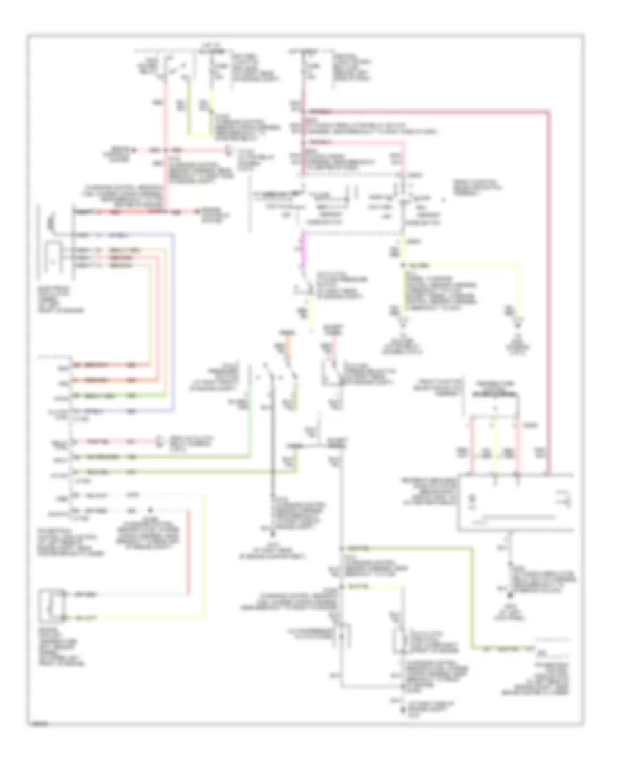
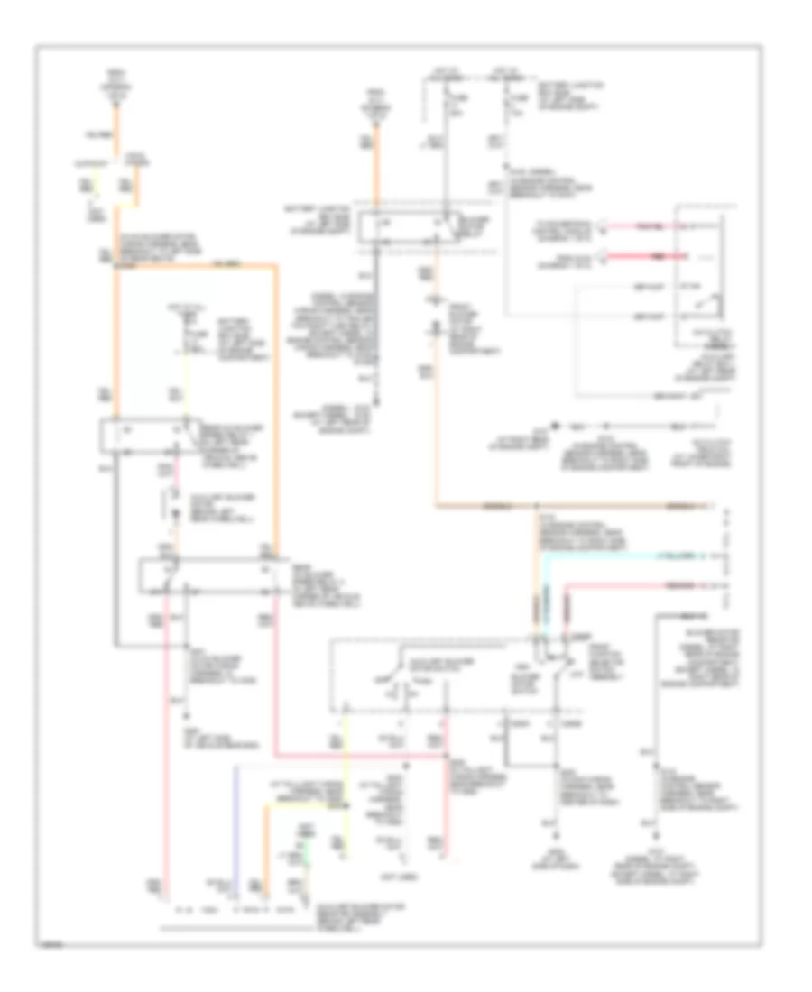
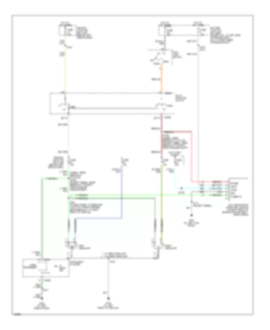
AIR CONDITIONING Manual A/C Wiring Diagram (1 of 2) for Ford Econoline E150 2004 List of elements for Manual A/C Wiring Diagram (1 of 2) for Ford Econoline E150 2004: 64 (at right side of engine compt) g107 (in engine control sensor & fuel charge wiring harness, near breakout to top center of engine) s1057 A/c clutch cycling pressure switch (at right rear of engine compt) A/c clutch field coil (on lower right front of engine) A/c compressor clutch diode A/c high pressure switch (in right rear of engine compt) A/c sw Battery junction box (bjb) (at right rear of engine compt) Breakout to c139) Breakout to front of engine) s1053 C176a C176c C294a C294d Central junction box box (cjb) (behind left side of dash) Clutch ctrl c176c Defrost Diesel Dual pressure switch (at right front of engine compt) Electronic fan clutch (diesel) (at left front of engine) Engine controls system Engine coolant temperature (ect) sensor (diesel) (on upper left front of engine) Except diesel Floor From a/c clutch relay (diagram 2 of 2) Front function selector switch assembly Fss Fuse 15a Fuse 30a G107 (at right rear of engine compartment) G204 (at left kick panel) Gnd Hot at all times Hot in run Input Max a/c Mix Mode switch Nca Norm a/c Off Pcm power relay Powertrain control module (pcm) (at left rear of engine compt, near master brake cylinder) Powertrain control module (pcm) (in left rear of engine compt, near brake master cylinder) Red Relay ctrl S1033 (in engine control sensor wiring harness, near breakout to starter relay) S1052 (in engine control sensor & fuel charge wiring harness, near breakout to front of engine) S1059 (in engine control sensor & fuel charge wiring harness, near breakout to rear left of engine compt) S142 (in engine control sensor harness, near breakout to right side of engine compt) S203 (in main wiring harness, near breakout to center of dash) S223 (in window regulator relay switch harness, near breakout to steering column) S242 (in window regulator relay switch harness, near breakout to right side of dash) Sig Sig rtn Temperature blend door actuator (behind right side of dash, on a/c heater plenum) Temperature control potentiometer To a/c clutch relay (diagram 2 of 2) To blower motor relay (diagram 2 of 2) To s400 (diagram 2 of 2) Vent Vent norm a/c Vpwr Vref Manual A/C Wiring Diagram (2 of 2) for Ford Econoline E150 2004 List of elements for Manual A/C Wiring Diagram (2 of 2) for Ford Econoline E150 2004: 49 (diesel) (diesel) (except diesel) (diesel: in engine control sensor wiring harness, near breakout to trailer tow right turn relay) (except diesel: in engine control sensor wiring harness, near breakout to g105) s1029 (in tailllight wiring harness, near breakout to c925) s303 (not used) 87a A/c clutch field coil (at lower right front of engine) A/c clutch relay (diesel) Auxiliary blower motor (behind left rear wheelwell) Auxiliary blower motor resistor assembly (behind left rear wheelwell) Auxiliary blower motor switch Auxiliary relay box 1 (at left rear of engine compt) Battery junction box (bjb) (at left side of engine compartment) Battery junction box (bjb) (at left side of engine compt) Blower motor relay Blower motor resistor (diesel: at right rear of engine compartment) (except diesel: in right rear of engine compartment) Blower motor switch C294b C294c Cutaway From s111 (diagram 1 of 2) From s142 (diagram 1 of 2) Front blower motor (at right rear of engine compartment) Front function selector switch assembly Fuse 10a Fuse 50a G100 g105 (at left rear of engine compt) G107 (at right rear of engine compt) G107 (diesel: at right rear of engine compt) (except diesel: at right side of engine compt) G202 (at left side of dash) G400 (at left side of vehicle rear end) High Hot at all times Low Of rear seats) s400 Off Rear a/c blower speed relay 1 (in left rear corner of vehicle, above wheelwell) Rear a/c blower speed relay 2 (in left rear corner of vehicle, above wheelwell) Red S143 (in engine control sensor harness, near breakout to right side of engine compartment) S143 (in engine control sensor harness, near breakout to right side of engine compt) S144 (in engine control sensor harness, near breakout to right side of engine compartment) S145 S202 (in main wiring harness, near breakout to center of dash) S304 (in taillight wiring harness, near breakout to c925) S305 (in taillight wiring harness, near breakout to c925) S401 (in a/c blower motor wiring harness, in breakout to c405) To powertrain control module (diagram 1 of 2) Van & wagon
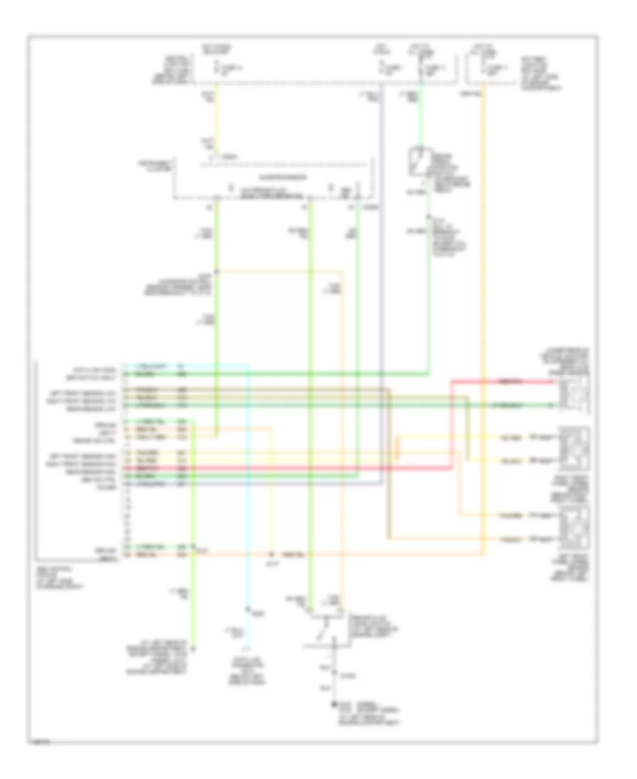
ANTI-LOCK BRAKES Anti-lock Brakes Wiring Diagram for Ford Econoline E150 2004 List of elements for Anti-lock Brakes Wiring Diagram for Ford Econoline E150 2004: 50 (at left rear of engine compartment) (at left rear of engine compartment) g105 (diesel) (diesel) (except diesel) (except diesel) (under rear of vehicle, mounted on differential) rear axle speed sensor Abs control module (at left side of engine compt) Abs ind Abs ind ctrl Battery junction box (bjb) (at left side of engine compartment) Bpp switch input Brake fluid level switch (at left rear of engine compt) Brake ind ctrl Brake pedal position switch (on bracket, above brake pedal) C220a C220b Central junction box (cjb) (behind left side of dash) Data link conn Data link connector (dlc) (below left side of dash) Fuse 1 5a Fuse 11 15a Fuse 11 60a Fuse 14 5a G100 g105 G121 (at left side of engine compartment) Ground Hot at all times Hot in run Hot in run or start Instrument cluster Left front sensor high Left front sensor low Left front wheel speed sensor (behind left front wheel) Low brake fluid level/ park brake ind Microprocessor Nca Power Rear sensor high Rear sensor low Red/pnk Right front sensor high Right front sensor low Right front wheel speed sensor (behind right front wheel) S1005 S147 S149 (in engine control sensor harness, near near breakout to c110) S174 (6.0l: in breakout to c219) (except 6.0l: in breakout to c110) S177 S226 Vbatt
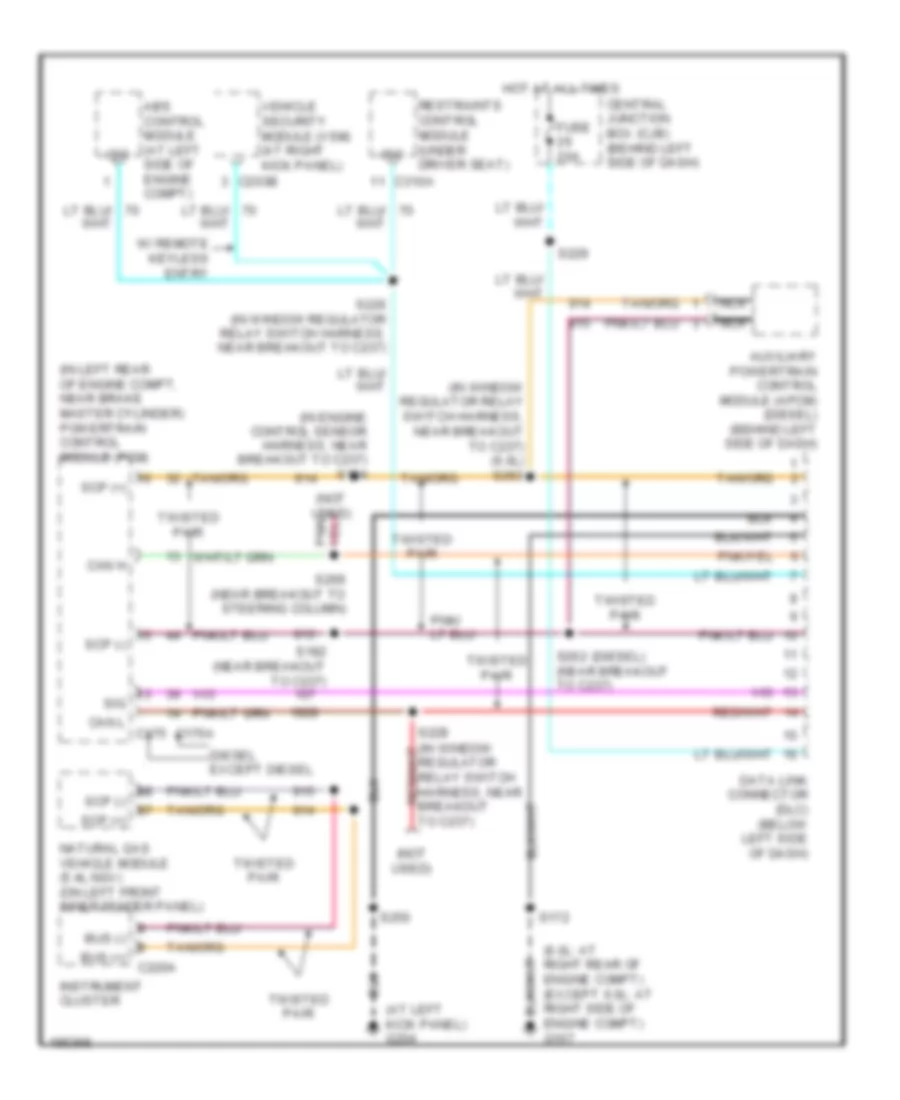
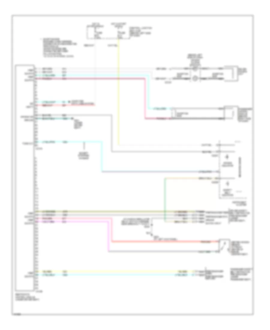
COMPUTER DATA LINES Computer Data Lines Wiring Diagram for Ford Econoline E150 2004 List of elements for Computer Data Lines Wiring Diagram for Ford Econoline E150 2004: 41 (6.0l: at right rear of engine compt) (except 6.0l: at right side of engine compt) g107 (at left kick panel) g204 (diesel) (in engine control sensor harness, near breakout to c237) s184 (in left rear of engine compt, near brake master cylinder) powertrain control module (pcm) (in window regulator relay switch harness, near breakout to c237) (6.0l) s263 (not used) Abs control module (at left side of engine compt) Auxiliary powertrain control module (apcm) (diesel) (behind left side of dash) Bus (+) Bus (-) C176a C203b C220a C310a Can h Can l c175 Central junction box (cjb) (behind left side of dash) Data link connector (dlc) (below left side of dash) Diesel except diesel Fuse 20a Hot at all times Instrument cluster Iso Natural gas vehicle module (5.4l ngv) (on left front inner fender panel) Nca Restraints control module (under driver seat) S172 S182 (near breakout to c237) S226 (in window regulator relay switch harness, near breakout to c237) S228 S229 S250 S262 (near breakout to c237) S269 (near breakout to steering column) Scp (+) Scp (-) Sig Twisted pair Vehicle security module (vsm) (at right kick panel) W/ remote keyless entry
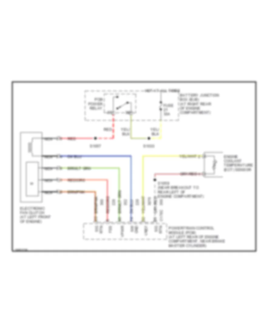
COOLING FAN Cooling Fan Wiring Diagram for Ford Econoline E150 2004 List of elements for Cooling Fan Wiring Diagram for Ford Econoline E150 2004: 19 Battery junction box (bjb) (at right rear of engine compartment) C176c rtn Electronic fan clutch (at left front of engine) Engine coolant temperature (ect) sensor Fss Fuse 30a Gnd Hot at all times Nca Pcm power relay Powertrain control module (pcm) (at left rear of engine compartment, near brake master cylinder) Red Rtn sig S1033 S1057 S1059 (near breakout to rear left of engine compartment) Sig Vpwr Vref
CRUISE CONTROL
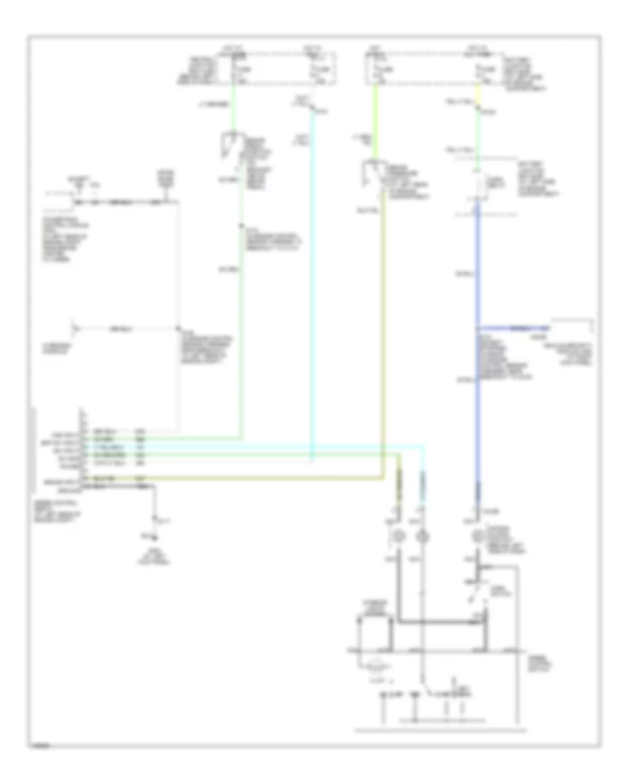
4.6L 4.6L, Cruise Control Wiring Diagram for Ford Econoline E150 2004 List of elements for 4.6L, Cruise Control Wiring Diagram for Ford Econoline E150 2004: 43 4r70e/ 4r75e/ 4r100 6.8l Air bag sliding contact (behind left side of dash) Battery junction box (bjb) (at left side of engine compartment) Bpp sw input Brake input Brake pedal position switch (on bracket, above brake pedal) Brake pressure switch (at left rear of engine compartment) C203b C218b Central junction box (cjb) (behind left side of dash) Coast Except 6.8l Fuse 10a Fuse 15a Fuse 2a G204 (at left kick panel) Ground Horn relay Horn switch Hot at all times Hot at all times Hot in run Illum Interior lights system Nca Off Overhead console Power Powertrain control module (pcm) (in left rear of engine compt, near brake master cylinder) Res S1034 S117 S124 S135 (in engine control sensor harness, near breakout to left rear of engine compt) S174 (in engine control sensor harness, in breakout to c110) Set/ accel Speed control servo (at left rear of engine compt) Speed control switch Sw gnd Sw input Vehicle security module (vsm) (at right kick panel) Vss input
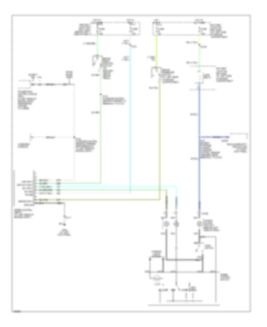
5.4L 5.4L, Cruise Control Wiring Diagram for Ford Econoline E150 2004 List of elements for 5.4L, Cruise Control Wiring Diagram for Ford Econoline E150 2004: 43 4r70e/ 4r75e/ 4r100 6.8l Air bag sliding contact (behind left side of dash) Battery junction box (bjb) (at left side of engine compartment) Bpp sw input Brake input Brake pedal position switch (on bracket, above brake pedal) Brake pressure switch (at left rear of engine compartment) C203b C218b Central junction box (cjb) (behind left side of dash) Coast Except 6.8l Fuse 10a Fuse 15a Fuse 2a G204 (at left kick panel) Ground Horn relay Horn switch Hot at all times Hot at all times Hot in run Illum Interior lights system Nca Off Overhead console Power Powertrain control module (pcm) (in left rear of engine compt, near brake master cylinder) Res S1034 S117 S124 S135 (in engine control sensor harness, near breakout to left rear of engine compt) S174 (in engine control sensor harness, in breakout to c110) Set/ accel Speed control servo (at left rear of engine compt) Speed control switch Sw gnd Sw input Vehicle security module (vsm) (at right kick panel) Vss input
ENGINE PERFORMANCE
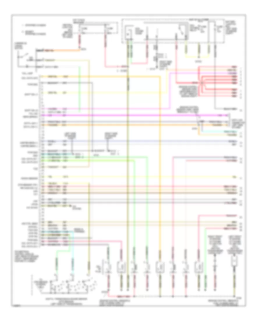
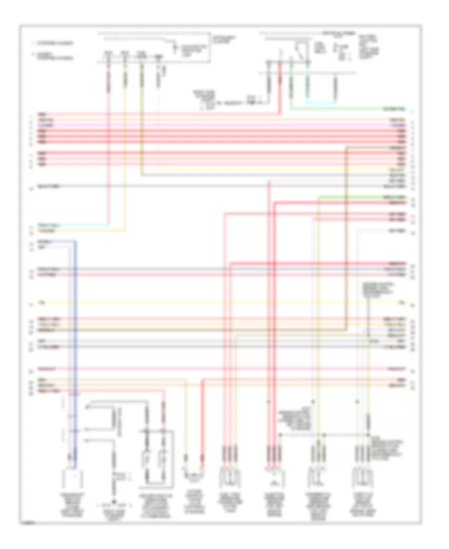
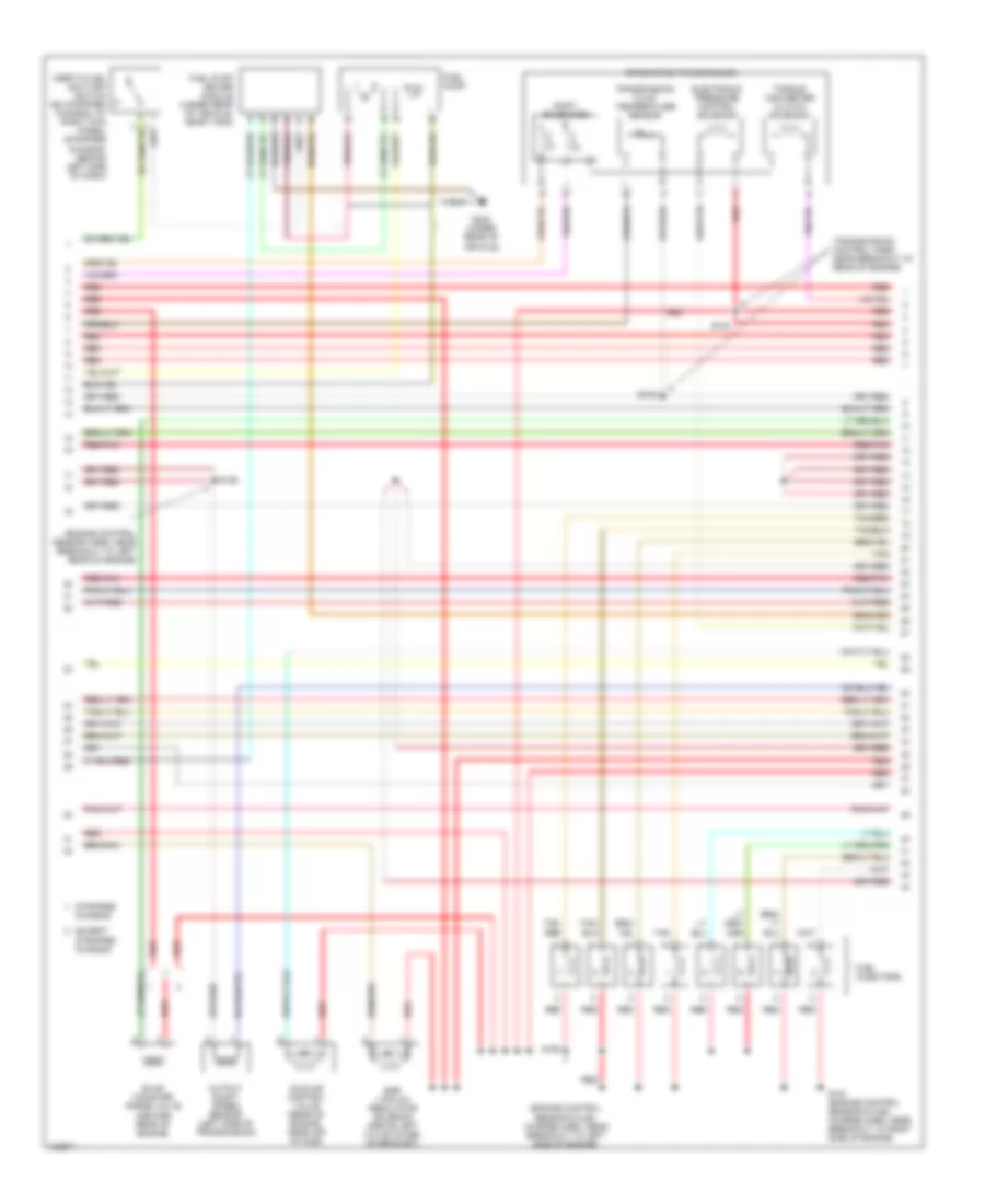
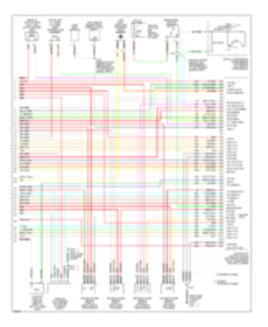
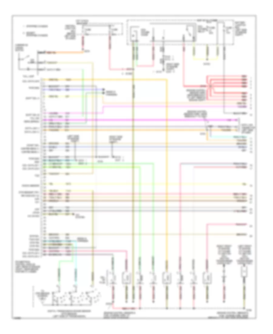
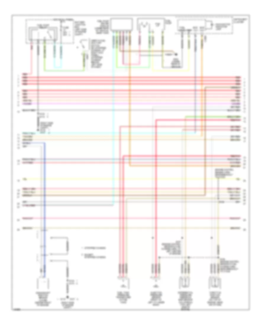
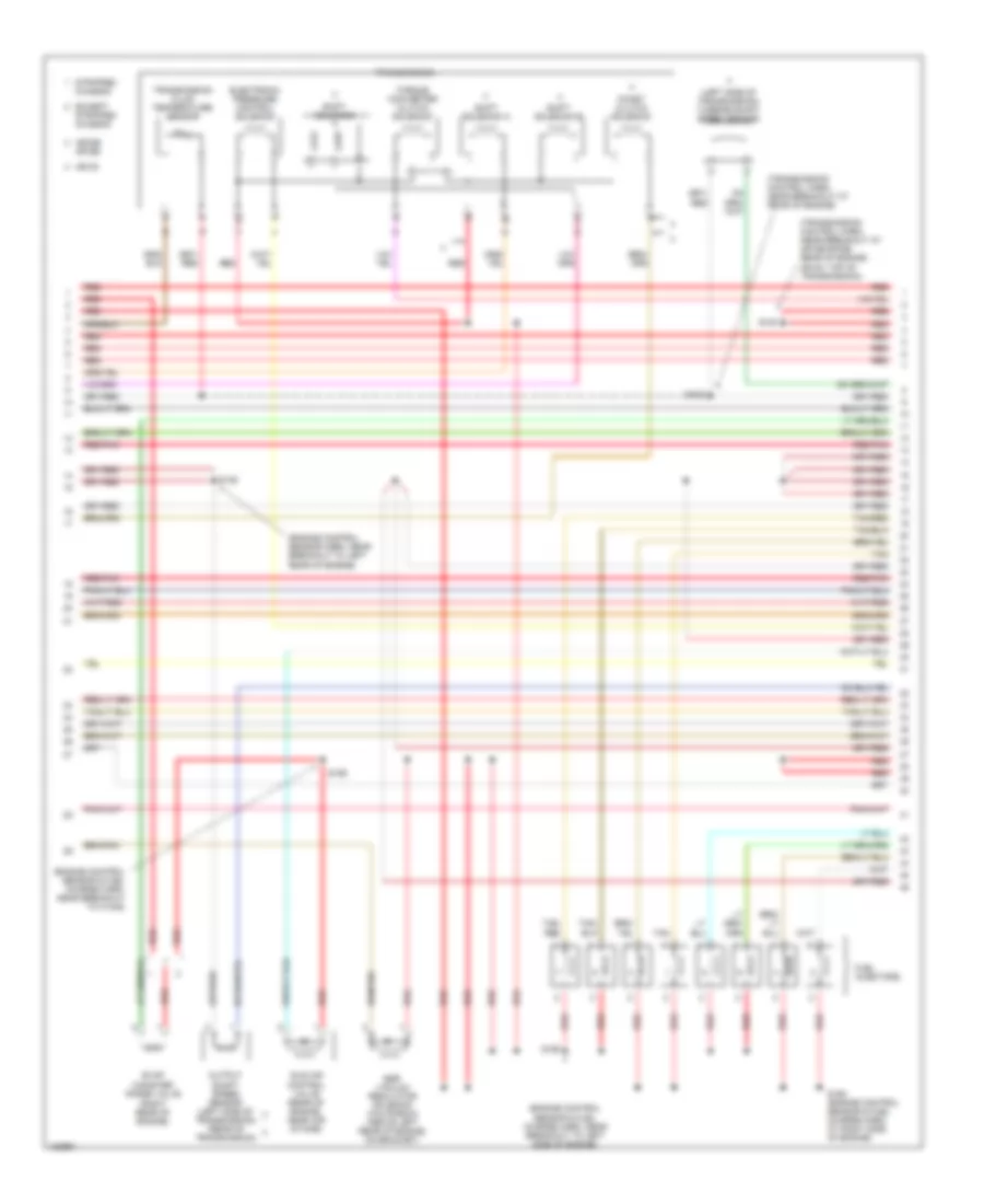
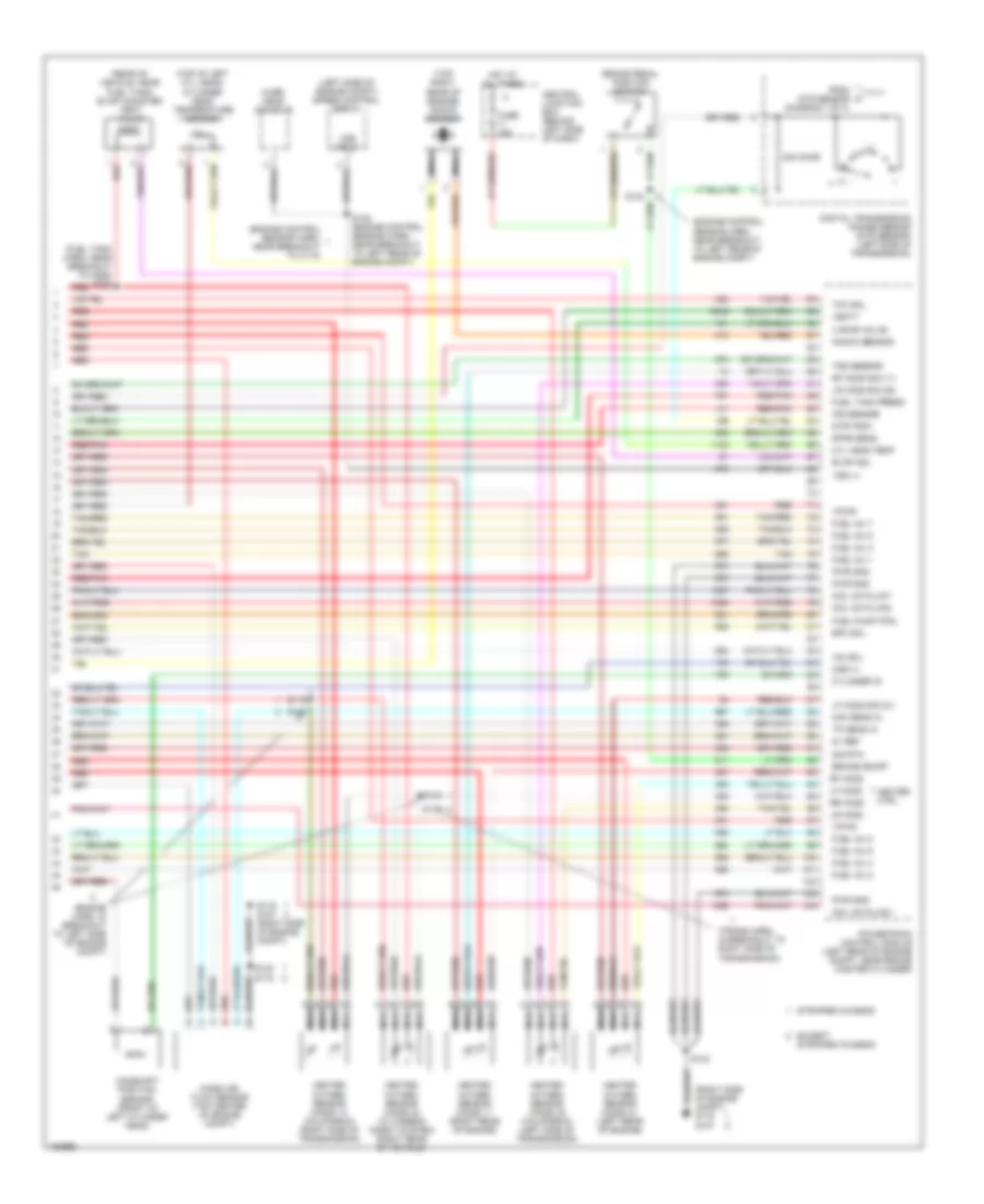
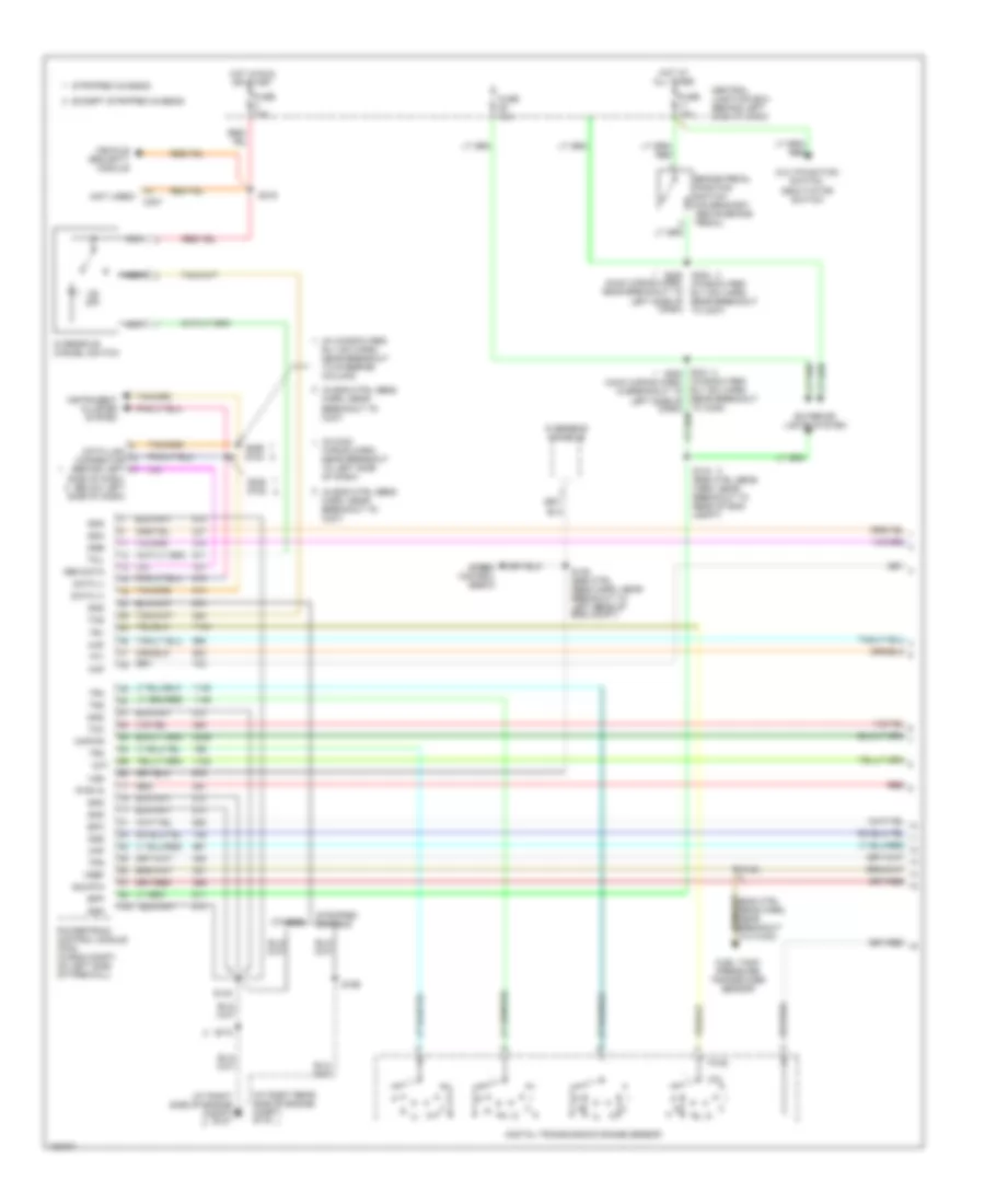
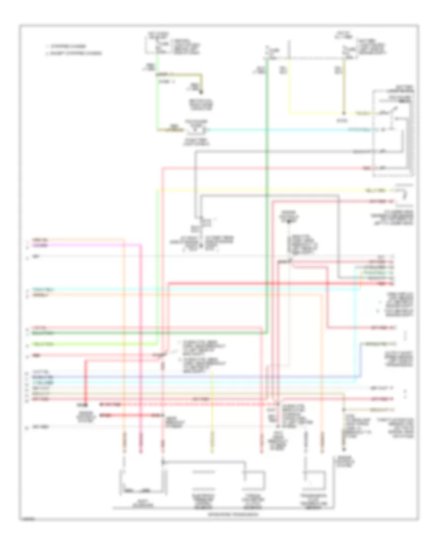
4.6L 4.6L, Engine Performance Wiring Diagram (1 of 4) for Ford Econoline E150 2004 List of elements for 4.6L, Engine Performance Wiring Diagram (1 of 4) for Ford Econoline E150 2004: 74 (ends in harness) (engine control sensor & fuel charge harn, at left side of engine) (engine control sensor & fuel charge harn, at right side of engine) (engine control sensor harn, near breakout to c237) (engine control sensor harn, near breakout to left rear of engine compt) (left front of engine, attached to ignition coil) ignition transformer capacitor 2 (left side of engine compt) (right front of engine, attached to ignition coil) ignition transformer capacitor 1 (right side of engine compt) (right side of engine compt) g107 A/c on sig A/c system Air ctrl sens Battery junction box (left side of engine compt) Central junction box (behind left side of dash) Coil on plug Coil on plug 1 Coil on plug 3 Coil on plug 4 Coil on plug 5 Coil on plug 6 Data link (+) Data link (-) Data link connector (left side of dash) Digital transmission range sensor (dtr sensor) (left side of transmission) Dtr sensor (tr1) Dtr-tr2 Dtr-tr4 Evr sol Except stripped chassis Feps (eprom) Fuse 10a Fuse 30a G100 G105 G107 G116 Gnd Hot at all times Hot in run or start Knock sensor Maf Misfire sens (+) Misfire sens (-) Nca O/d off Overdrive cancel switch Pcm power diode Pcm power relay Powertrain control module (left rear of engine compt, near brake master cylinder) Pwr gnd R n Red Rr ho2s sig (12) S1033 S1065 S127 S140 S142 S156 S161 S182 S184 S216 Shift sol a Shift sol b Stripped chassis Tach sig Tcil ind Tcil lamp Tcs Tft To dtr sensor (diagram 4 of 4) Vpwr 4.6L, Engine Performance Wiring Diagram (2 of 4) for Ford Econoline E150 2004 List of elements for 4.6L, Engine Performance Wiring Diagram (2 of 4) for Ford Econoline E150 2004: 32 (engine control sensor harn, near breakout to c1033) (right side of engine compt) (right side of engine compt) g116 g107 Battery junction box (left side of engine compt) Bus (+) Bus (-) Crankshaft position sensor (lower right front of engine) Differential pressure feedback egr sensor (top left rear of engine) Except stripped chassis Fuel level Fuel pump relay Fuel tank pressure transducer (in fuel tank) Fuse 30a 20a G107 G116 Heated positive crankcase ventilation (pcv) element (top of right cylinder bank) Hot at all times Injection pressure sensor (top left side of engine) Instrument cluster Intake manifold tuning valve (top front of engine) Malfunction indicator lamp Nca Red Red/pnk S138 S140 S157 (engine control sensor & fuel charge harn, at left center of engine) S158 (engine control sensor & fuel charge harn, near breakout to c1045) S172 Stripped chassis Throttle position sensor (on top of engine, near air intake) Vref 4.6L, Engine Performance Wiring Diagram (3 of 4) for Ford Econoline E150 2004 List of elements for 4.6L, Engine Performance Wiring Diagram (3 of 4) for Ford Econoline E150 2004: 30 (center rear of engine) (engine control sensor & fuel charge harn, near breakout to left side of engine) (engine control sensor harn, near breakout to left rear of engine) (transmission control harn, near breakout at rear of engine) 4r70e/4r75e transmission Egr vacuum regulator solenoid (above left valve cover, on bracket) Electronic pressure control solenoid Evap canister purge valve Except stripped chassis Fuel injectors Fuel pump Fuel pump driver module (under rear of vehicle, near tank) G302 (under rear of vehicle) Idle air control valve (rear of engine, near air intake) Inertia fuel shut-off switch (ex stripped chassis: at right kick panel) (stripped chassis: behind left side of dash) Output shaft speed sensor (left side of transmission) Red Red/pnk S100 S102 S136 S151 (engine control sensor & fuel charge harn, near breakout to right side of engine) S152 Shift solenoids Stripped chassis Tan Tan/ red Tan/red Torque converter clutch solenoid Transmission fluid temperature sensor 4.6L, Engine Performance Wiring Diagram (4 of 4) for Ford Econoline E150 2004 List of elements for 4.6L, Engine Performance Wiring Diagram (4 of 4) for Ford Econoline E150 2004: 75 (engine control sensor harn, near breakout to left rear of engine compt) (left side of engine compt) speed control servo (rear of vehicle, near fuel tank) evap canister vent valve (right side of engine compt) g116 g107 (top of left cyl head) cylinder head temperature sensor (top right rear side of engine) knock sensor 240 ohms 5v ref Brake on/off Brake pedal position switch Camshaft position sensor (front of left cylinder head) Central junction box (behind left side of dash) Coil on plug 2 Coil on plug 7 Coil on plug 8 Cyl head temp Cylinder id Digital transmission range sensor (dtr sensor) (left side of transmission) Dpfe sens Dtr-tr3a Epc sol Evap sol Except stripped chassis From dtr sensor (diagram 1 of 4) Fuel inj 1 Fuel inj 2 Fuel inj 3 Fuel inj 4 Fuel inj 5 Fuel inj 6 Fuel inj 7 Fuel inj 8 Fuel pump ctrl Fuel tank press Fuse 15a G116 g107 (right side of engine compt) Heated oxygen sensor (ho2s) 11 (right rear of engine) Heated oxygen sensor (ho2s) 12 (right side of transmission) Heated oxygen sensor (ho2s) 21 (left rear of engine) Heated oxygen sensor (ho2s) 22 (left side of transmission) Heater ctrl Hot at all times Iac sol Ips sensor Knock sensor Lf ho2s Lf ho2s sig (21) Lr ho2s Lr ho2s sig (22) Maf sens in Mass air- flow sensor (top center of engine compt) Nca Oss (+) Over- head console Powertrain control module (left rear of engine compt, near brake master cylinder) Pwr gnd Red Red/pnk Rf ho2s Rf ho2s sig (11) Rr ho2s S135 (engine control sensor harn, near breakout to left rear of engine compt) S140 S172 Sig rtn Stripped chassis Tan Tan/red Tcc sol Tp sens in Vapor valve Vbatt Vpwr Vss (+) Vss input
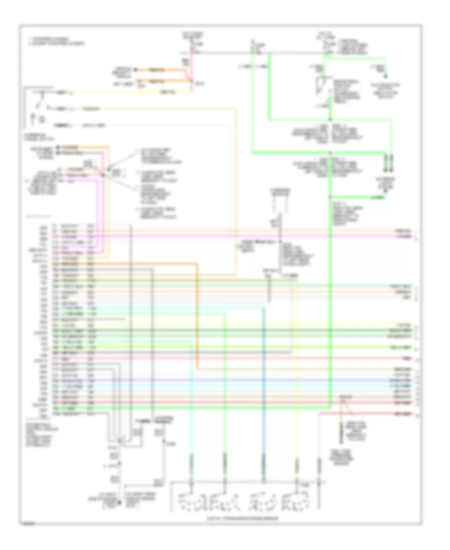
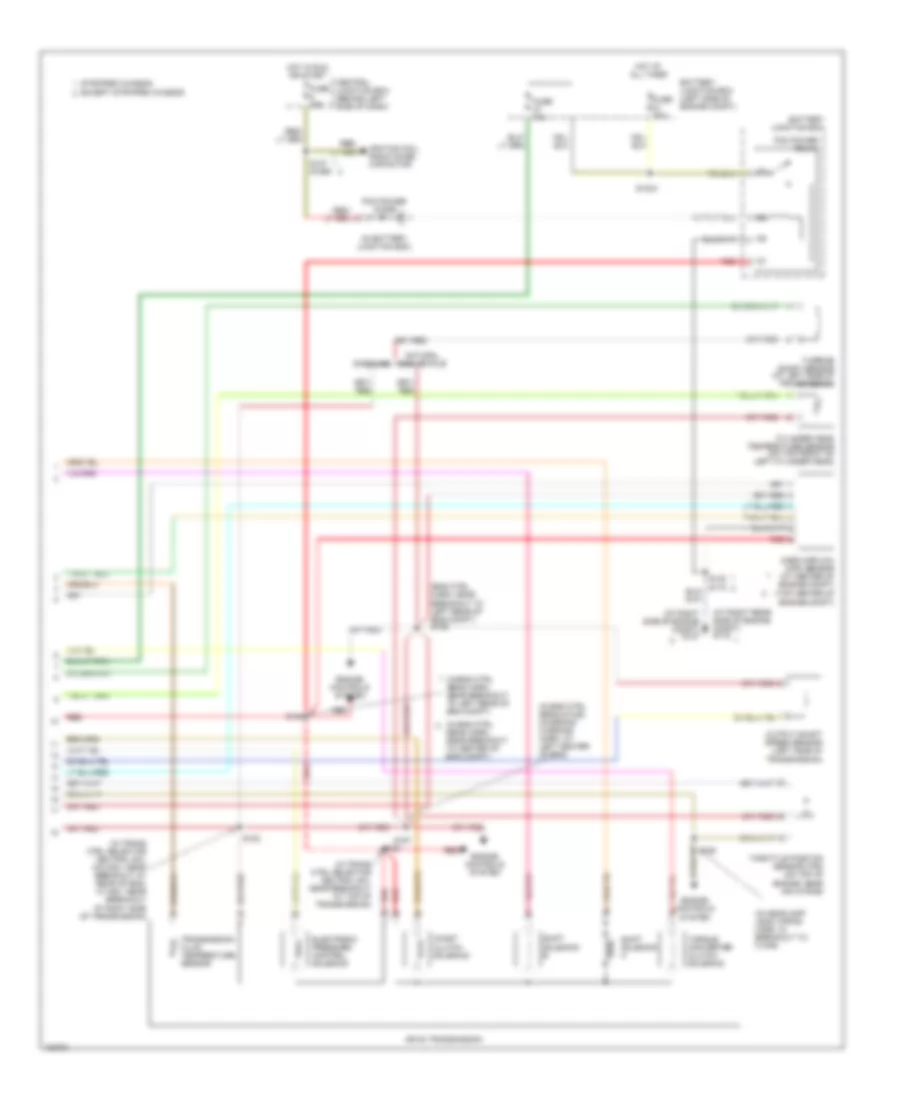
5.4L 5.4L, Engine Performance Wiring Diagram (1 of 4) for Ford Econoline E150 2004 List of elements for 5.4L, Engine Performance Wiring Diagram (1 of 4) for Ford Econoline E150 2004: 74 (ends in harness) (engine control sensor & fuel charge harn, at right side of engine) (engine control sensor & fuel charge harn, near breakout to left side of engine) (engine control sensor harn, near breakout to c237) (engine control sensor harn, near breakout to left rear of engine compt) (left front of engine, attached to ignition coil) ignition transformer capacitor 2 (left side of engine compt) (right front of engine, attached to ignition coil) ignition transformer capacitor 1 (right side of engine compt) (right side of engine compt) g107 A/c on sig A/c system Battery junction box (left side of engine compt) Central junction box (behind left side of dash) Coast sol Coil on plug Coil on plug 1 Coil on plug 3 Coil on plug 4 Coil on plug 5 Coil on plug 6 Data link (+) Data link (-) Data link connector (left side of dash) Digital transmission range sensor (dtr sensor) (left side of transmission) Dtr sensor (tr1) Dtr-tr2 Dtr-tr4 Evr sol Except stripped chassis Feps (eprom) Fuse 10a Fuse 30a G100 G105 G107 G116 Gnd Hot at all times Hot in run or start Knock sensor Maf Misfire sens (+) Misfire sens (-) Nca O/d off Overdrive cancel switch Pcm power diode Pcm power relay Powertrain control module (left rear of engine compt, near brake master cylinder) Pwr gnd R n Red Rr ho2s sig (12) S1033 S1065 S127 S140 S142 S156 S161 S182 S184 S216 Shift sol a Shift sol b Stripped chassis Tach sig Tcil ind Tcil lamp Tcs Tft To dtr sensor (diagram 4 of 4) Vpwr 5.4L, Engine Performance Wiring Diagram (2 of 4) for Ford Econoline E150 2004 List of elements for 5.4L, Engine Performance Wiring Diagram (2 of 4) for Ford Econoline E150 2004: 33 (engine control sensor harn, near breakout to c1033) (right side of engine compt) (right side of engine compt) g116 g107 Battery junction box (left side of engine compt) Bus (+) Bus (-) Crankshaft position sensor (lower center front of engine) Differential pressure feedback egr sensor (california) (top left side of engine) Except stripped chassis Fuel level Fuel pump Fuel pump driver module (under rear of vehicle, near tank) Fuel pump relay Fuel tank pressure transducer (in fuel tank) Fuse 30a 20a G107 G116 G302 (under rear of vehicle) Hot at all times Inertia fuel shut-off switch (ex stripped chassis: at right kick panel) (stripped chassis: behind left side of dash) Injection pressure sensor (front of left cylinder bank) Instrument cluster Malfunction indicator lamp Red Red/pnk S138 S140 S157 (engine control sensor & fuel charge harn, at left center of engine) S158 (engine control sensor & fuel charge harn, near breakout to c1045) S172 Stripped chassis Throttle position sensor (on top of engine, near air intake) Vref 5.4L, Engine Performance Wiring Diagram (3 of 4) for Ford Econoline E150 2004 List of elements for 5.4L, Engine Performance Wiring Diagram (3 of 4) for Ford Econoline E150 2004: 35 (engine control sensor & fuel charge harn, near breakout to c1045) (engine control sensor & fuel charge harn, near breakout to left side of engine) (engine control sensor harn, near breakout to left rear of engine) (left side of transmission) turbine shaft speed sensor (right rear of engine) (transmission control harn, near breakout at 4r70e/4r75e: rear of engine, 4r100: top of transmission) (transmission control harn, near breakout at rear of engine) 4r100 4r70e/ 4r75e Coast clutch solenoid Egr vacuum regulator solenoid (california) (above left rear of engine, on bracket) Electronic pressure control solenoid Evap canister purge valve Except stripped chassis Fuel injectors Idle air control valve (rear of engine, near air intake) Output shaft speed sensor (left side of transmission) (rear of transmission) Red Red/pnk S100 S102 S136 S155 S159 S160 (engine control sensor & fuel charge harn, at right side of engine) Shift solenoid Shift solenoid a Shift solenoid b Stripped chassis Tan Tan/ red Tan/red Torque converter clutch solenoid Transmission Transmission fluid temperature sensor 5.4L, Engine Performance Wiring Diagram (4 of 4) for Ford Econoline E150 2004 List of elements for 5.4L, Engine Performance Wiring Diagram (4 of 4) for Ford Econoline E150 2004: 85 (engine control sensor harn, near breakout to c110) (engine control sensor harn, near breakout to left rear of engine compt) (engine harn, in breakout to left side of engine compt) (fuel tank harn, near breakout to c925) s324 (left side of engine compt) speed control servo (rear of vehicle, near fuel tank) evap canister vent valve (right side of engine compt) g116 g107 (top of left cyl head) cylinder head temperature sensor (top right rear of engine) knock sensor (trans harn, in breakout to right side of transmission) 240 ohms 5v ref Brake on/off Brake pedal position switch Camshaft position sensor (front of left cylinder head) Central junction box (behind left side of dash) Coil on plug 2 Coil on plug 7 Coil on plug 8 Cyl head temp Cylinder id Digital transmission range sensor (dtr sensor) (left side of transmission) Dpfe sens Dtr-tr3a Epc sol Evap sol Except stripped chassis From dtr sensor (diagram 1 of 4) Fuel inj 1 Fuel inj 2 Fuel inj 3 Fuel inj 4 Fuel inj 5 Fuel inj 6 Fuel inj 7 Fuel inj 8 Fuel pump ctrl Fuel tank press Fuse 15a G116 g107 (right side of engine compt) Heated oxygen sensor (ho2s) 11 (right rear of engine) Heated oxygen sensor (ho2s) 12 (california) (right side of transmission) Heated oxygen sensor (ho2s) 21 (left rear of engine) Heated oxygen sensor (ho2s) 22 (california) (left side of transmission) Heated oxygen sensor (ho2s) 23 (w/ carbon mngmt system) (right rear of vehicle) Heater ctrl Hot at all times Iac sol Ips sensor Knock sensor Lf ho2s Lf ho2s sig (21) Lr ho2s Lr ho2s sig (22) Maf sens in Mass air- flow sensor (top center of engine compt) Nca Oss (+) Over- head console Powertrain control module (left rear of engine compt, near brake master cylinder) Pwr gnd Red Red/pnk Rf ho2s Rf ho2s sig (11) Rr ho2s S119 S123 S135 (engine control sensor harn, near breakout to left rear of engine compt) S140 S172 S179 S186 Sig rtn Stripped chassis Tan Tan/red Tcc sol Tp sens in Tss sensor Vapor valve Vbatt Vpwr Vss (+) Vss input
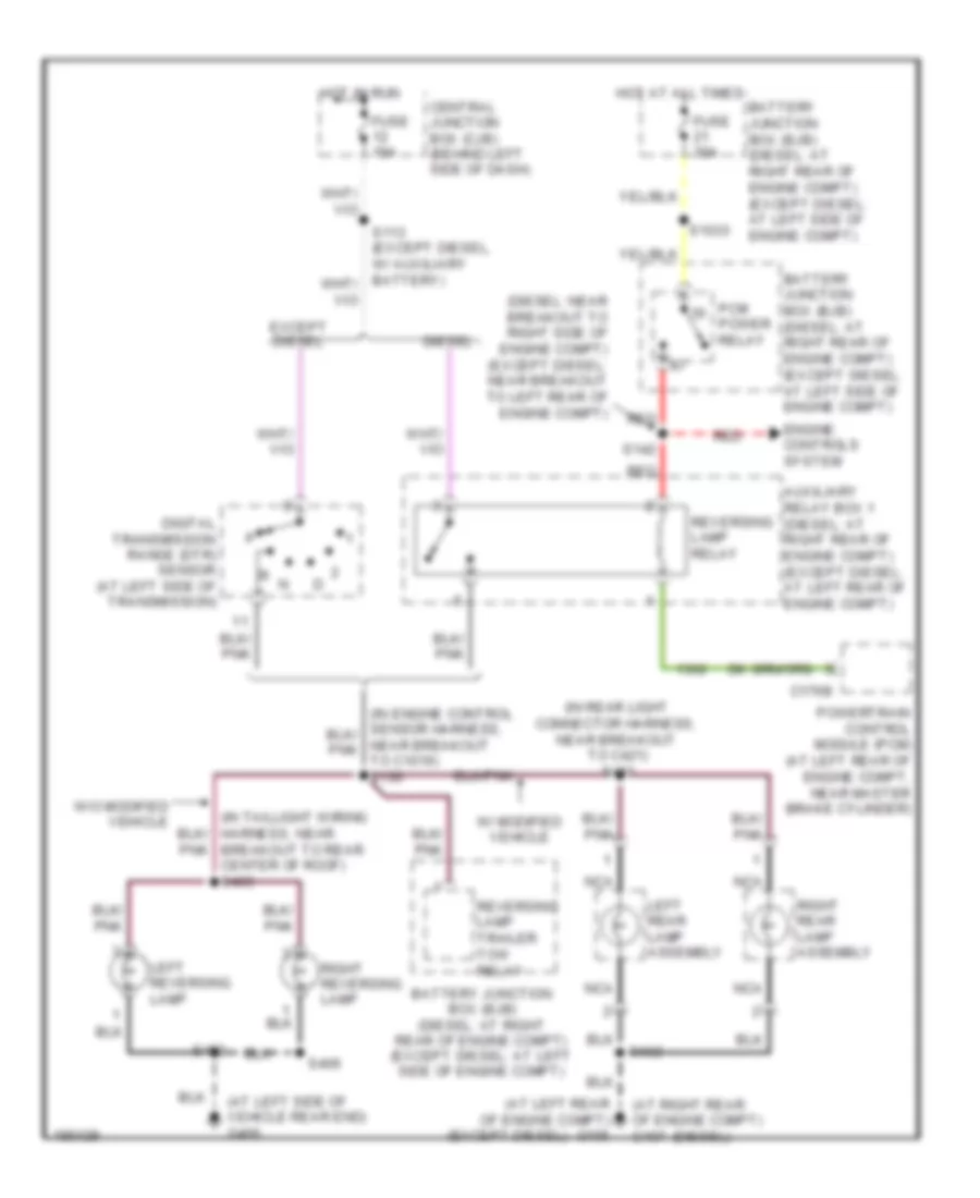
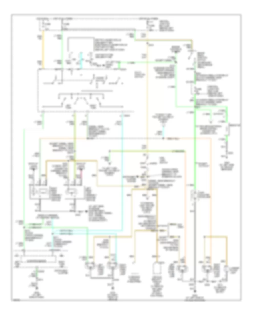
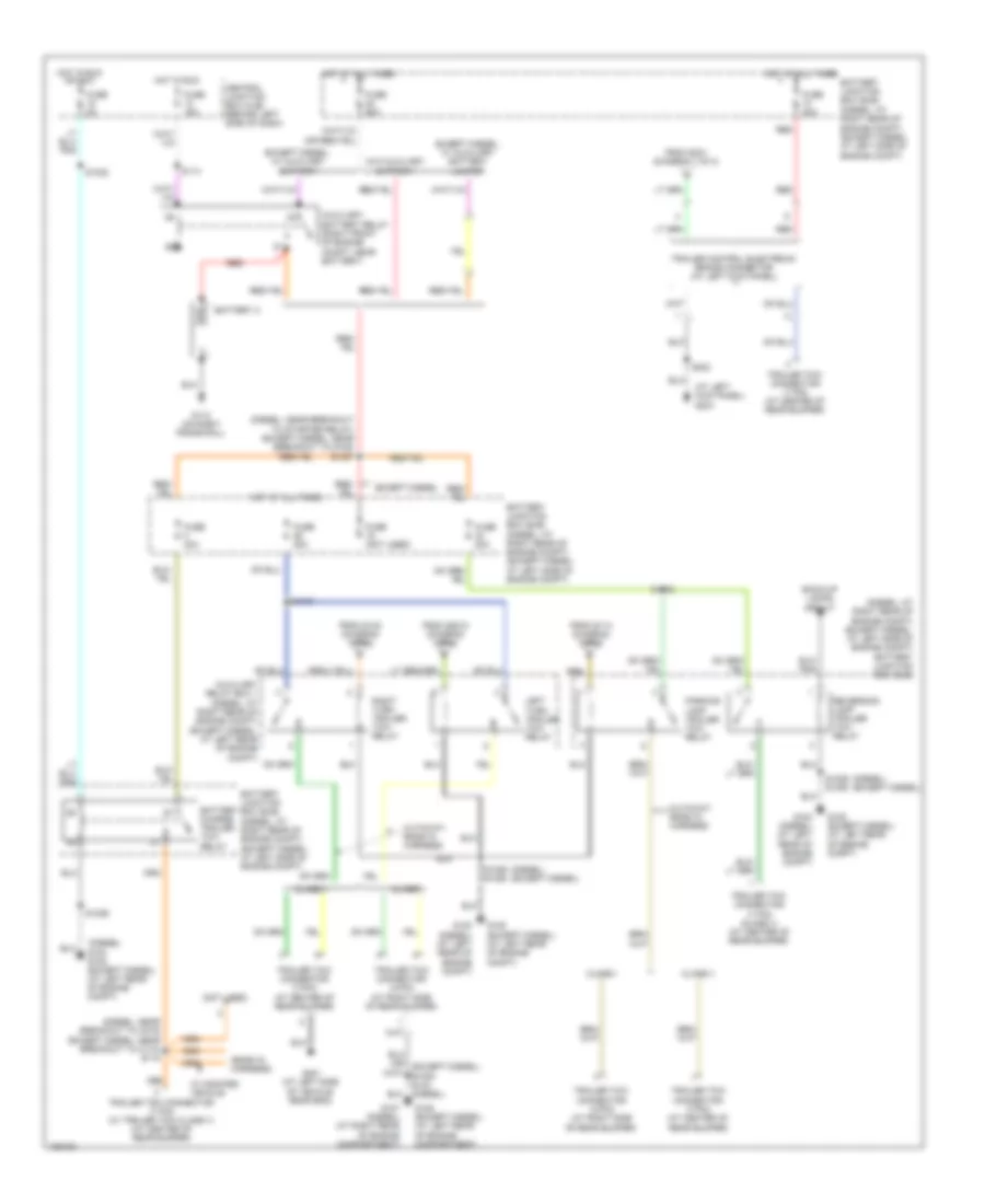
EXTERIOR LIGHTS Backup Lamps Wiring Diagram for Ford Econoline E150 2004 List of elements for Backup Lamps Wiring Diagram for Ford Econoline E150 2004: 38 (at left rear of engine compt) g105 (at left side of vehicle rear end) g400 (at right rear of engine compt) g107 (diesel) (diesel: near breakout to right side of engine compt) (except diesel: near breakout to left rear of engine compt) (except diesel) (in rear light connector harness, near breakout to c421) s431 Auxiliary relay box 1 (diesel: at right rear of engine compt) (except diesel: at left rear of engine compt) Battery junction box (bjb) (diesel: at right rear of engine compt) (except diesel: at left side of engine compt) Breakout to rear center of roof) s403 C176b Central junction box (cjb) (behind left side of dash) Diesel Digital transmission range (dtr) sensor (at left side of transmission) Engine controls system Except diesel Fuse 15a Fuse 30a Hot at all times Hot in run Left rear lamp assembly Left reversing lamp Nca Pcm Power relay Powertrain control module (pcm) (at left rear of engine compt, near master brake cylinder) Red Reversing lamp relay Reversing lamp trailer tow relay Right rear lamp assembly Right reversing lamp S1033 S142 S402 S406 S432 W/ modified vehicle W/o modified vehicle Exterior Lamps Wiring Diagram (1 of 2) for Ford Econoline E150 2004 List of elements for Exterior Lamps Wiring Diagram (1 of 2) for Ford Econoline E150 2004: 77 (at left kick panel) g204 (at left rear of engine compartment) g105 g107 (at right rear of engine compt) (diesel: near breakout to c140) (except diesel: near breakout to c237) s132 (ends in harness) (w/ modified vehicle) (except diesel) (diesel) (except diesel: near breakout to c219) (diesel: near breakout to c140) s2010 (in main wiring harness, near breakout to steering column) (in window regulator relay switch harness, near breakout to c248) s231 (near breakout to c311) (w/ remote keyless entry or overhead console) s234 (not used) Back-up lamps circuit Batt Brake pedal position switch (on bracket, above brake pedal) C202a C203a C220a C220b Central junction box (cjb) (behind left side of dash) Cutaway Engine controls system Except cutaway Except diesel Factory-fitted dealer-fitted Fuse 10a Fuse 15a Fuse 20a G103 (at right front of vehicle) G202 (at left side of dash) G400 (at left side of vehicle rear end) Grote flasher module (dealer-fitted) electronic flasher module (factory-fitted) (behind left side of dash) Hazard switch Head High mounted stoplamp Hot at all times Hot in run Ign Instrument cluster Instrument cluster system Left front park/ turn lamp Left rear lamp assembly (modified vehicle) Left rear park/ stop/ turn lamp Left turn Left turn ind License plate lamp Main light switch Microprocessor Multi- function switch Nca Off Overhead console (if equipped) Park Resistor Right front park/ turn lamp Right rear lamp assembly (modified vehicle) Right rear park/ stop/ turn lamp Right turn Right turn ind S134 (in engine control sensor harness, near breakout to left rear of engine compt) S163 S165 (near breakout to g103) S206 (diesel: near breakout to c1019) (except diesel: near breakout to g107) s114 S214 S215 (in main wiring harness, near breakout to g203) S218 S223 S224 (in window regulator relay switch harness, near breakout to c237) S235 S306 (near breakout to top center rear of vehicle) S402 S406 S414 (w/ remote keyless entry) S432 To left turn trailer tow relay (diagram 2 of 2) To parking lamp trailer tow relay (diagram 2 of 2) To right turn trailer tow relay (diagram 2 of 2) To trailer electronic brake control connector (diagram 2 of 2) Vehicle security module (vsm) (w/ remote keyless entry) (at right kick panel) Exterior Lamps Wiring Diagram (2 of 2) for Ford Econoline E150 2004 List of elements for Exterior Lamps Wiring Diagram (2 of 2) for Ford Econoline E150 2004: 61 (at left kick panel) g204 (diesel) (except diesel) (diesel) g100 g105 (except diesel) (at left rear of engine compt) (diesel: at right rear of engine compt) (except diesel: at left side of engine compt) battery junction box (bjb) (diesel: near breakout to c219) (except diesel: near breakout to c110) s118 (diesel: near breakout to starter relay) (except diesel: near breakout to g105) s1027 (ends in harness) (not used) Auxiliary battery relay (right front of engine compt, near battery) Auxiliary relay box 1 (diesel: at right rear of engine compt) (except diesel: at left rear of engine compt) Back-up lamps circuit Battery 2 Battery charge trailer tow relay Battery junction box (bjb) (diesel: at right rear of engine compt) (except diesel: at left side of engine compt) Central junction box (cjb) (behind left side of dash) Class i Class ii Cutaway: ends in harness Except diesel Except diesel, w/ auxiliary battery Except diesel, w/ auxiliary battery jumper From s114 (diagram 1 of 2) From s132 (diagram 1 of 2) From s2010 (diagram 1 of 2) From s231 (diagram 1 of 2) Fuse (not used) Fuse 15a Fuse 20a Fuse 30a Fuse 40a Fuse 5a Fuse 60a G100 (diesel) (at left rear of engine compt) G105 (except diesel) (at left rear of engine compartment) G105 (except diesel) (at left rear of engine compt) G107 (diesel) (at right rear of engine compartment) G110 (on right frame rail) G401 (at left side of vehicle rear end) Hot at all times Hot in run Hot in run or acc Left turn trailer tow relay Parking lamp trailer tow relay Red Reversing lamp trailer tow relay Right turn trailer tow relay S1019 S1022 S1029 S1029 s1005 S1032 S113 S223 Trailer control electronic brake connector (at left kick panel) Trailer tow connector (4-pin) (at right side of rear bumper) Trailer tow connector (7 pin) (at center of rear bumper) Trailer tow connector (7 pin) (class ii) (at center of rear bumper) Trailer tow connector (7 pin) (w/ trailer tow class ii) (at center of rear bumper) Trailer tow connector (7-pin) (at center of rear bumper) W/ modified vehicle W/o auxiliary battery
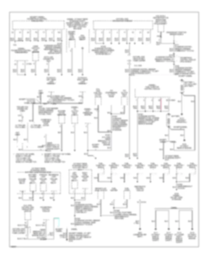
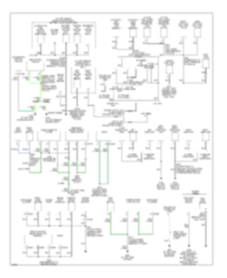
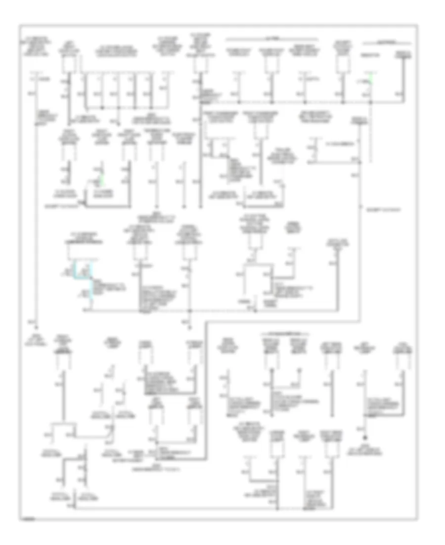
GROUND DISTRIBUTION Ground Distribution Wiring Diagram (1 of 3) for Ford Econoline E150 2004 List of elements for Ground Distribution Wiring Diagram (1 of 3) for Ford Econoline E150 2004: 85 (4.6l & 6.8l) heated positive crankcase ventilation (pcv) element (5.4l cng) fuel rail cutoff valve (5.4l cng) natural gas vehicle (ngv) module (at right rear of engine compt) auxiliary relay box 1 (at right rear of engine compt) battery junction box (bjb) (at right rear of engine compt) g107 (cutaway) left rear lamp assembly (cutaway) right rear lamp assembly (diesel) a/c clutch field coil (diesel) dual pressure switch (diesel) fuel injector control module (diesel) powertrain control module (pcm) (diesel: at right rear of engine compt) (except diesel: at left side of engine compt) battery junction box (bjb) (except diesel) fuel pump relay (except diesel) powertrain control module (pcm) (except diesel: at left side of engine compt) (diesel: at left rear of engine compt) g100 (near breakout to rear left of engine compt) (5.4l cng) s1069 (not used) 5.4l cng 6.8l A/c clutch field coil A/c compressor clutch diode Base w/ trailer Battery Battery charge Battery ii (w/ auxiliary battery) Blower motor relay Blower motor resistor Brake fluid level switch C1388c C176a C310a Crankshaft position sensor shield Data link connector (dlc) Diesel Except cutaway with 138" wheel base Except diesel Except van with 138" wheel base w/ trailer Fuel heater Fuel injector 1 shield Fuel injector 2 shield Fuel injector 3 shield Fuel injector 4 shield Fuel injector 5 shield Fuel injector 6 shield Fuel injector 7 shield Fuel injector 8 shield Fuel pump G108 (diesel) (on left side of engine) G110 (on right frame rail) G111 (at right side of engine compt) G117 (at right side of engine compt) G118 (at lower right side of engine compt) G119 (at right front of engine) G120 (at right rear of engine) G201 (under driver seat) Harness, in breakout to left side of engine compt) s172 In breakout to c134) Left turn trailer tow relay Mass air flow (maf) sensor Natural gas vehicle (ngv) module Natural gas vehicle (ngv) timer jumper Nca Parking lamp Pcm power relay Powertrain control module Powertrain control module (pcm) shield Restraints control module Reversing lamp Right turn trailer tow relay S1035 (in engine control sensor wiring harness, near breakout to starter relay) S1051 (5.4l cng) (near breakout to front of engine) S1061 (in engine control sensor & fuel charge wiring harness, near breakout to left rear of engine) S1066 (in fuel pump feed jumper wiring harness, near breakout for c1386) S140 (in engine control sensor harness, near breakout to left rear of engine compt) S170 (in engine control sensor harness, in breakout to c134) S307 (in fuel tank sender wiring harness, near breakout to fuel tank) S432 Tow class ii or van w/ 138" wheel base w/o trailer tow Trailer tow connector (4-pin) Trailer tow relay Van with 138" wheel W/ trailer tow class i W/ trailer tow class ii Windshield washer pump motor Ground Distribution Wiring Diagram (2 of 3) for Ford Econoline E150 2004 List of elements for Ground Distribution Wiring Diagram (2 of 3) for Ford Econoline E150 2004: 90 (at left rear of engine compt) auxiliary relay box 1 (at left side of engine compartment) battery junction box (bjb) (at right side of dash) g200 (cutaway) left rear lamp assembly (cutaway) right rear lamp assembly (late production) horn (not used) (w/ five fuel tanks) extended range fuel tank valve 1 (w/ five fuel tanks) extended range fuel tank valve 2 5.4l cng Abs control module Air bag sliding contact Alternative fuel control module (afcm) diode Battery charge trailer tow relay Blower motor relay Brake fluid level switch Brake shift interlock C176a C2188a C218b C220a C220b C294b C294c C294e C3077a Diesel Except 5.4l cng Except diesel Except van w/ 138" wheel base & trailer tow class ii Front aft-axle fuel tank valve Front cigar lighter Front function selector switch assembly Fuel pump driver module Fuel pump shield G102 (at left front of vehicle) G103 (at right front of vehicle) G105 (at left rear of engine compt) G121 (at left side of engine compt) G202 (at left side of dash) G302 (cutaway: at rear underbody of vehicle) (except cutaway: at rear of vehicle, near fuel pump module) G401 (at left side of vehicle rear end) Instrument cluster Left front park/turn lamp Left headlamp Left turn trailer tow relay Left video display Main light switch Midship fuel tank valve Nca Parking brake switch Parking lamp trailer tow relay Pony tank valve Power point Powertrain control module Radio Rear aft-axle fuel tank valve Rear seat entertainment (rse) module Reversing lamp trailer tow relay Right front park/turn lamp Right headlamp Right turn trailer tow relay Right video display S1005 (in engine control sensor wiring harness, near breakout to c146) S1029 (in engine control sensor wiring harness, near breakout to g105) S202 (near breakout to center of dash) S204 (in main wiring harness, near breakout to center of dash) S207 (in main wiring harness, near breakout to center of dash) S214 (in main wiring harness, near breakout to g203) S297 (near breakout to c311) S312 (near breakout to fuel tank) S317 (in fuel tank sender wiring harness, near breakout to fuel tank) S320 (in breakout to rear underside of vehicle) S322 (w/ 5 fuel tanks) (near breakout to c3149) S323 (near center of console) To c421) To fuel tank) Trailer tow connector (7-pin) Trailer tow connector, 4-pin Van w/ 138" wheel base & trailer tow class ii Video cassette player W/ 138" wheel base W/ 158" wheel base or higher W/ aero headlamps W/ rse W/ sealed beam headlamps W/ trailer tow class i W/ trailer tow class ii W/o 138" wheel base Wiper control module (wcm) Ground Distribution Wiring Diagram (3 of 3) for Ford Econoline E150 2004 List of elements for Ground Distribution Wiring Diagram (3 of 3) for Ford Econoline E150 2004: 71 (at right side of vehicle rear end) s406 (diesel) auxiliary powertrain control module (apcm) (except cutaway) power point (in taillight wiring harness, near breakout to c411) s402 (in window regulator relay switch harness, near breakout to left side of dash) s250 (near breakout to c3052) s233 (w/ daytime running lamps) daytime running lamps (drl) module (w/ overhead console) overhead console (w/ power locks) master window/door lock/unlock switch (w/ power mirrors) exterior rear view mirror switch (w/ power seats) driver side front seat adjust switch (w/ remote keyless entry) rear doors door lock switch (w/ remote keyless entry) vehicle security module (vsm) C203a C203b C3077a Cargo lamp Cutaway Data link connector (dlc) Diesel Driver safety belt retractor pretensioner Electronic flasher module Ends in harness Except cutaway Except diesel Front interior/ map lamps assembly Front passenger window/door lock switch G204 (at left kick panel) G400 (at left side of vehicle rear end) High mounted stoplamp Interior lamp Left front door ajar switch Left rear park/stop/ turn lamp Left reversing lamp Left video display License plate lamp Nca Power point console 1 Power point console 2 Rear a/c blower speed relay 1 Rear a/c blower speed relay 2 Rear doors door ajar switch Rear interior lamp Rear seat entertainment (rse) module Resistor Right front door ajar switch Right rear park/stop/ turn lamp Right reversing lamp Right side door ajar switch Right sliding door ajar switch Right video display S117 (near breakout to left side of engine compt) S223 (near breakout to steering column) S300 (near breakout to c311) S414 (w/ remote keyless entry) S500 (near breakout in top of driver door) S600 (near breakout to center of passenger door) S915 (near breakout to c925) Speed control servo Temperature blend door actuator Trailer electronic brake control connector W/ auxiliary a/c W/ conversion W/ full headliner W/ hinged side door W/ rear seat entertainment W/ remote keyless entry W/ rse W/ sliding cargo door W/o full headliner W/o remote keyless entry
HEADLIGHTS Headlights Wiring Diagram for Ford Econoline E150 2004 List of elements for Headlights Wiring Diagram for Ford Econoline E150 2004: 44 507/13 527/12 Battery junction box (bjb) (except 6.0l: at left side of engine compt) (6.0l: at right rear of engine compt) C202b C220a C220b Central junction box (cjb) (behind left side of dash) Daytime running lamps (drl) module (in right front of engine compartment, near horns) Fuse 10a Fuse 15a Fuse 20a Fuse 30a Fuse 5a G102 (at left front of vehicle) G202 (at left side of dash) G204 (at left kick panel) Gnd Head Hi beam in Hi beam ind Hot at all times Hot in run or acc Instrument cluster Left headlamp Main light switch Micro- processor Multi- function switch Off Park Pass Power Right headlamp S1022 S1025 (diesel: near breakout to c1019) (except diesel: near breakout to right side of engine compt) S117 (except diesel) S145 (6.0l) S163 S164 (in dash panel to headlamp junction wiring harness, near breakout to right front of vehicle) S214 S218 Vbatt Vpwr W/ aero headlamp W/o aero headlamp
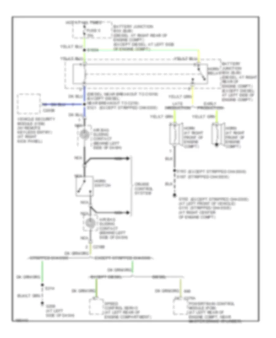
HORN Horn Wiring Diagram for Ford Econoline E150 2004 List of elements for Horn Wiring Diagram for Ford Econoline E150 2004: 30 (except stripped chassis) (stripped chassis) 15a Air bag sliding contact (behind left side of dash) Battery junction box (bjb) (diesel: at right rear of engine compt) (except diesel: at left side of engine compt) C176a C203b C218b Cruise control system Diesel Early production Except diesel Except stripped chassis Fuse 5 G102 (at left front of vehicle) g115 (at right center of engine compt) G208 (at left side of dash) Horn (at right front of engine compt) Horn relay Horn switch Hot at all times Late production Nca Powertrain control module (pcm) (at left rear of engine compt, near master brake cylinder) S1034 S163 S197 S214 Speed control servo (at left rear of engine compartment) Stripped chassis Vehicle security module (vsm) (w/ remote keyless entry) (at right kick panel)
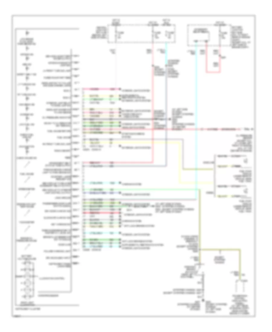
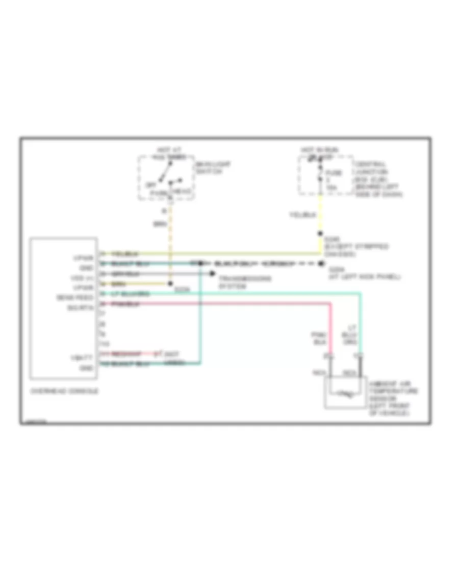
INSTRUMENT CLUSTER Overhead Console Wiring Diagram for Ford Econoline E150 2004 List of elements for Overhead Console Wiring Diagram for Ford Econoline E150 2004: 24 (not Ambient air temperature sensor (left front of vehicle) Central junction box (cjb) (behind left side of dash) Fuse 15a G204 (at left kick panel) Gnd Head Hot at all times Hot in run or acc Main light switch Nca Off Overhead console Park S234 S245 (except stripped chassis) S930 Sens feed Sig rtn Transmissions system Used) Vbatt Vpwr Vss (+)
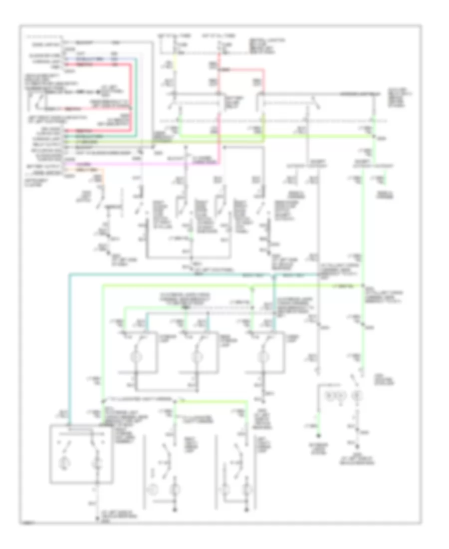
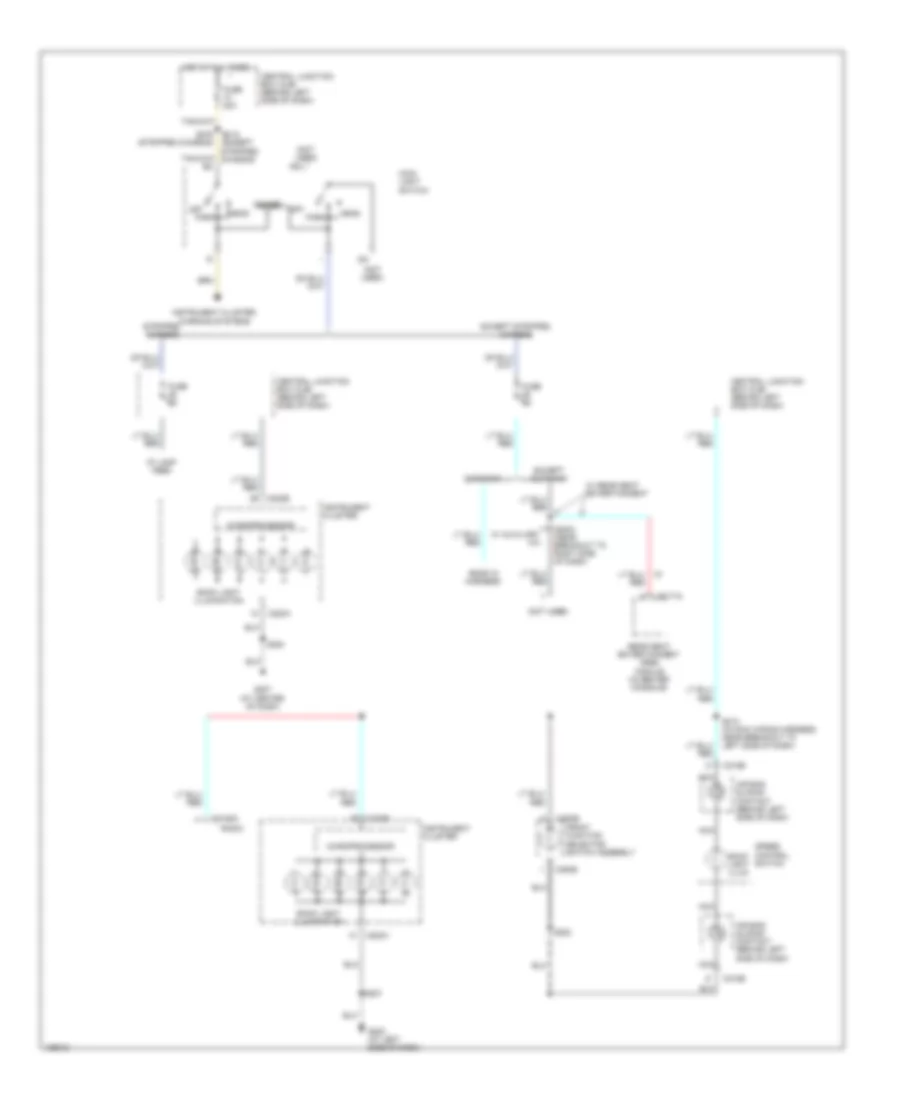
INTERIOR LIGHTS Courtesy Lamps Wiring Diagram for Ford Econoline E150 2004 List of elements for Courtesy Lamps Wiring Diagram for Ford Econoline E150 2004: 64 (at left kick panel) g204 (at left side of vehicle rear end) g400 (in interior lamps wiring harness, near breakout to center of roof) s911 (in interior lamps wiring harness, near breakout to center of roof) s912 (in taillight wiring harness, near breakout to c311) s301 (near breakout to c3007) (near breakout to left side of dash) Auxiliary relay box 2 (behind center of dash) Battery output Battery saver relay C203a C203b C220a Cargo lamp Central junction box (cjb) (behind left side of dash) Cutaway Dome lamp sw Drv door ajar sw sig Ends in harness Except cutaway Exterior lights system Front interior/ map lamps assembly Fuse 15a G202 (at left side of dash) G400 (at left side of vehicle rear end) High mounted stoplamp Hot at all times Instrument cluster Interior Interior lamp Interior lamp relay Left front door ajar switch (at left kick panel) Left vanity mirror lamp Main light switch Nca Rear doors door ajar switch (except cutaway) Rear interior lamp Red/pnk Relay output dr ajar sw sig sliding door ajar sw sig c220b Right front door ajar switch (at right kick panel) Right side door ajar switch (in front of right side door) Right sliding door ajar switch (at right "b" pillar) Right vanity mirror lamp S205 S209 S214 S223 S233 S253 S256 (w/ remote keyless entry) S265 S302 (in taillight wiring harness, near breakout to c311) S314 (in interior light wiring harness, near breakout for left front of roof) S402 S404 S405 S913 Sliding dr wire Vehicle security module (vsm) (w/ remote keyless entry) (at right kick panel) Vref W/ hinged cargo door W/ illuminated vanity mirrors W/ sliding cargo door Warning lamp Instrument Illumination Wiring Diagram for Ford Econoline E150 2004 List of elements for Instrument Illumination Wiring Diagram for Ford Econoline E150 2004: 46 (not used) Air bag sliding contact (behind left side of dash) Back light illum Back light illumination C2188a C218b C220a C220b C294e C3077a Central junction box (cjb) (behind left side of dash) Cutaway Dimmer Ends in harness Except cutaway Except stripped chassis Front function selector switch assembly Fuse 20a Fuse 5a G202 (at left side of dash) G207 (at center of dash) Head Hot at all times I/p lamp feed Ign Instrument cluster Instrument cluster, warning systems Main light switch Microprocessor Nca Off Park Radio Rear seat entertainment (rse) module (in center console) Red S2004 (near breakout to right side of dash) S202 S207 S212 (in main wiring harness, near breakout to left side of dash) S218 (except stripped chassis) S276 (stripped chassis) S284 Speed control switch Stripped chassis W/ auxiliary a/c W/ rear seat entertainment
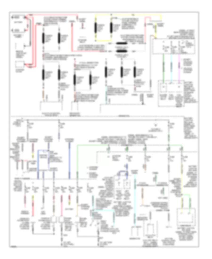
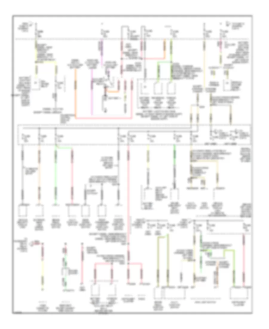
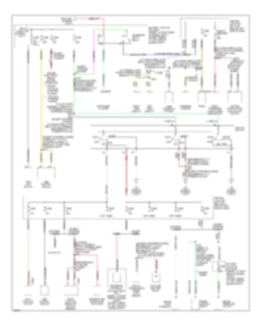
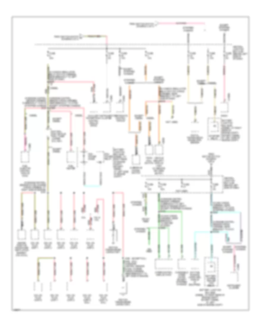
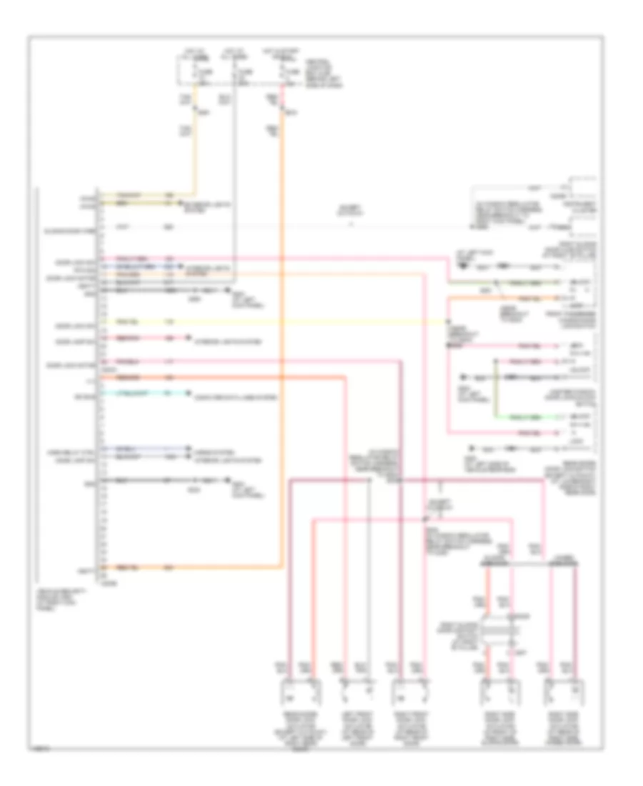
POWER DISTRIBUTION Power Distribution Wiring Diagram (1 of 4) for Ford Econoline E150 2004 List of elements for Power Distribution Wiring Diagram (1 of 4) for Ford Econoline E150 2004: 94 (at front of center console) (at left kick panel) g204 (at left side of dash) g202 (at right rear of engine compt) (diesel) (diesel: at right rear of engine compt) (except diesel: at left side of engine compt) (diesel: at right rear of engine compt) (except diesel: at left side of engine compt) battery junction box (bjb) (diesel: near breakout to trailer tow right turn relay) (diesel: near breakout to trailer tow right turn relay) (except diesel: near breakout to g105) (except diesel: near breakout to g105) (except stripped chassis) s1028 (except diesel: near breakout to g105) (diesel: near breakout to c237) s2012 (except diesel: near breakout to g105) (diesel: near breakout to starter relay) s1034 (in alternator rectifier system wiring harness, near breakout to right side of engine) s1071 (in alternator rectifier system wiring harness, near breakout to top left rear of engine) s1076 (in engine control sensor harness, near breakout to g107) s145 (in starter relay to fuse junction panel harness, in breakout to right side of engine compt) (in starter relay/battery wiring harness, in breakout to left side of engine compt) s1074 (in window regulator relay switch harness, near breakout to steering column) (near breakout to c1101) (near breakout to c1101) s1054 (near breakout to top left rear of engine) red s1073 (not used) (stripped chassis) s1031 4.6l & 5.4l A/c clutch relay Auxiliary relay Auxiliary relay box 1 (except stripped chassis) (diesel: at right rear of engine compt) (except diesel: at left rear of engine compt) Battery Battery feed Battery ii (diesel) Battery junction box (bjb) Battery junction box (bjb) (diesel: at right rear of engine compt) (except diesel: at left side of engine compt) Battery junction box (bjb) (stripped chassis) (diesel: at right rear of engine compt) (except diesel: at left side of engine compt) Blower motor relay Box 1 C102a C1251a C1301a C1301b Central junction box (cjb) (behind left side of dash) Chassis Chassis) Console 1 power point (w/ rse) Console 2 power point (w/ rse) (at front of center console) Cutaway Data link connector (dlc) Daytime running lamps (drl) module (if equipped) Diesel Ends in harness Except Except 4.6l & 5.4l stripped chassis Except cutaway Except diesel Except stripped chassis From a fuse 19 (diagram 1 of 4) Front cigar lighter (except stripped chassis) Fuel injector control module (ficm) power relay Fuel pump relay Fuse 10a Fuse 15a Fuse 20a Fuse 20a 30a Fuse 30a Fuse 50a Fuse 50a (diesel) Fuse 60a Generator Glow plug control module (gpcm) Horn relay Left turn trailer tow relay Modified vehicle Nca Power point (behind left "b" pillar) Power point (except cutaway) (behind left "b" pillar) Red Remote jump start terminal (diesel) Right turn trailer tow relay S1008 S1019 S1055 S1056 (in engine control sensor & fuel charge wiring harness, near breakout to c1101) S1072 (in alternator rectifier system wiring harness, near breakout to right side of engine) S1075 (in alternator rectifier system wiring harness, near breakout to top left rear of engine) S207 S235 S266 (w/o rse: near breakout to to central junction box) Secondary generator Starter motor Starter relay Starter relay (diesel) Stripped Stripped chassis To fuse 21 (diagram 2 of 4) To fuse 9 (diagram 1 of 4) W/ dual generators W/ single generators Power Distribution Wiring Diagram (2 of 4) for Ford Econoline E150 2004 List of elements for Power Distribution Wiring Diagram (2 of 4) for Ford Econoline E150 2004: 88 (behind left side of dash) central junction box (cjb) (diesel) (except diesel) (except diesel: near breakout to g105) (except diesel: near breakout to g105) (diesel: near breakout to starter relay) s1033 (except diesel: near breakout to right side of dash) (diesel: near breakout to left side of dash) s291 (in main wiring harness, in breakout to c219) (in main wiring harness, near breakout to center of dash) s205 (in main wiring harness, near breakout to left side of dash) s219 (in main wiring harness, near breakout to left side of dash) s221 (in main wiring harness, under left side of dash) s276 (in window regulator relay switch harness, near breakout to c248) s237 (in window regulator relay switch harness, near breakout to right side of dash) (w/ remote keyless entry) s261 (not used) Auxiliary battery relay Auxiliary relay box 2 (behind center of dash) Battery charge trailer tow relay Battery ii Battery junction box (bjb) (diesel: at right rear of engine compt) (except diesel: at left side of engine compt) Battery saver relay Brake pedal position switch C175 C176a C202a batt C202b C203a C2188a C220a C220b C3077a Central junction box (cjb) (behind left side of dash) Courtesy sw feed Cutaway Diesel and all w/o auxiliary battery Driver side front seat adjust switch Ends in harness Except cutaway Except modified vehicles Except stripped chassis Exterior rear view mirror switch From b fuse 18 (diagram 1 of 4) From fuse 4 (diagram 2 of 4) From fuse 5 (diagram 2 of 4) Front passenger window/ door lock switch Fuse Fuse (except diesel) Fuse 10a Fuse 15a Fuse 20a Fuse 30a Fuse 40a Fuse 50a Fuse 5a Fuse 60a Fuse fuse 30a 30a Gasoline w/ auxiliary battery Gasoline w/ auxiliary battery jumper Instrument cluster Interior lamp relay Main light switch Master window/ door lock/ unlock switch Multi- function switch Nca Parking lamp trailer tow relay Pcm power relay Power choke 1 Powertrain control module (pcm) Radio Rear a/c blower speed relay 1 Rear doors door lock switch Rear seat entertainment (rse) module Red Reversing lamp trailer tow relay S1027 (diesel: near breakout to starter relay) S1032 (diesel: in engine control sensor wiring harness, near breakout to starter relay) (except diesel: near breakout to g105) S218 S225 Stripped chassis To accessory delay relay (diagram 3 of 4) To fuse 10 (diagram 2 of 4) To fuse 15 (diagram 3 of 4) To fuse 17 (diagram 2 of 4) Vehicle security module (vsm) Vehicle security module (vsm) (w/ remote keyless entry) Video cassette player W/ auxiliary a/c W/ power locks, w/o remote keyless entry W/ remote keyless entry Power Distribution Wiring Diagram (3 of 4) for Ford Econoline E150 2004 List of elements for Power Distribution Wiring Diagram (3 of 4) for Ford Econoline E150 2004: 76 (except stripped chassis: in breakout to c110) (stripped chassis: in breakout to left side of engine compt) s177 (in interior lamps wiring harness, near breakout to c925) (in main wiring harness, in breakout to steering column) (stripped chassis) s280 (in window regulator relay switch harness, near breakout to c237) s245 (in window regulator relay switch harness, near breakout to right side of dash) s242 (in window regulator relay switch harness, near breakout to steering column) (in window regulator relay switch harness, under left side of dash) s236 (near breakout in top of driver door) s501 (near breakout to left side of dash) (stripped chassis) s281 s271 (except stripped chassis) (near breakout to steering column) (not used) (w/ auxiliary battery) s113 4.6l & 5.4l stripped chassis A/c switch Abs control module Acc Accessory delay relay Auxiliary battery relay Battery junction box (bjb) (diesel: at right rear of engine compt) (except diesel: at left side of engine compt) Brake pressure switch Brake shift interlock C202a C2188a C220b C294a Central junction box (cjb) (behind left side of dash) Circuit breaker 20a Diesel Digital transmission range (dtr) sensor Except Except diesel Except stripped chassis From e fuse 14 (diagram 2 of 4) From s291 f (diagram 2 of 4) Front function selector switch assembly Front passenger window/door lock switch Fuse Fuse 10a Fuse 15a Fuse 2a Fuse 30a Fuse 30a 40a Fuse 5a Fuse 60a Ign Ignition switch Instrument cluster Left video display Lock Main light switch Master window/door lock/unlock switch Multi- function switch Off Overhead console Pnk/ Radio Red Reversing lamp relay auxiliary relay box 1 (diesel: at right rear of engine compt) (except diesel: at left rear of engine compt) Right video display Run S124 (diesel: in breakout to c237) (except diesel: near breakout to left side of engine compt) S203 S227 S230 (except stripped chassis) (in window regulator relay switch harness, near breakout to steering column) S914 Speed control servo Start Stripped chassis Temperature blend door actuator To fuse 14 (diagram 4 of 4) To fuse 33 (diagram 4 of 4) To fuse 9 (diagram 4 of 4) Trailer electronic brake control connector Video cassette player W/ overhead console W/ power door locks W/ rse Power Distribution Wiring Diagram (4 of 4) for Ford Econoline E150 2004 List of elements for Power Distribution Wiring Diagram (4 of 4) for Ford Econoline E150 2004: 75 (6.8l) (except 6.8l) (in engine control (in engine control sensor harness, in breakout to g112) (stripped chassis) s127 (in engine control sensor & fuel charge wiring harness, at right side of engine) s161 (in engine control sensor harness, in breakout to left rear of engine compt) (except stripped chassis) s128 (in engine control sensor wiring harness, near breakout to g107) s1022 (in main wiring harness, near breakout to c219) (stripped chassis) s282 (in main wiring harness, near breakout to center of dash) s208 (in window regulator relay switch harness, near breakout to left side of dash) s246 (not used) (w/ remote keyless entry) 4.6l & 5.8l 6.8l Auxiliary powertrain control module (apcm) Battery charge trailer tow relay Battery junction box (bjb) (diesel: at right rear of engine compt) (except diesel: at left side of engine compt) C1388c C203b C2188a C220a C220b C310a Cancel switch Central junction box (cjb) (behind left side of dash) Central junction box (cjb) (behind left side of of dash) Coil on plug (cop) 1 Coil on plug (cop) 10 (6.8l) Coil on plug (cop) 2 Coil on plug (cop) 3 Coil on plug (cop) 4 Coil on plug (cop) 5 Coil on plug (cop) 6 Coil on plug (cop) 7 Coil on plug (cop) 8 Coil on plug (cop) 9 (6.8l) Daytime running lamps (drl) module (if equipped) Diesel Digital transmission range (dtr) sensor Except diesel Except stripped chassis From ignition switch (diagram 3 of 4) From ignition switch k (diagram 3 of 4) From ignition switch l (diagram 3 of 4) Fuel heater Fuel injector control module (ficm) Fuse Fuse 10a Fuse 15a Fuse 30a Fuse 5a Haul switch Heated positive crankcase ventilation element (4.6l & 6.8l) Ign feed Ign sw feed Ignition transformer capacitor 1 Ignition transformer capacitor 2 Instrument cluster Natural gas vehicle (ngv) timer jumper (5.4l ngv) Nca Overdrive Pcm power diode Pcm power relay Radio Restraints control module S156 S162 (in engine control sensor & fuel charge wiring harness, near breakout to left side of engine) Security module (vsm) Sensor wiring harness, near breakout to c1760) (except stripped chassis) s1065 Starter relay Stripped chassis Tan/red Town/ Vehicle Windshield wiper motor (except stripped chassis) Wiper control module (wcm)
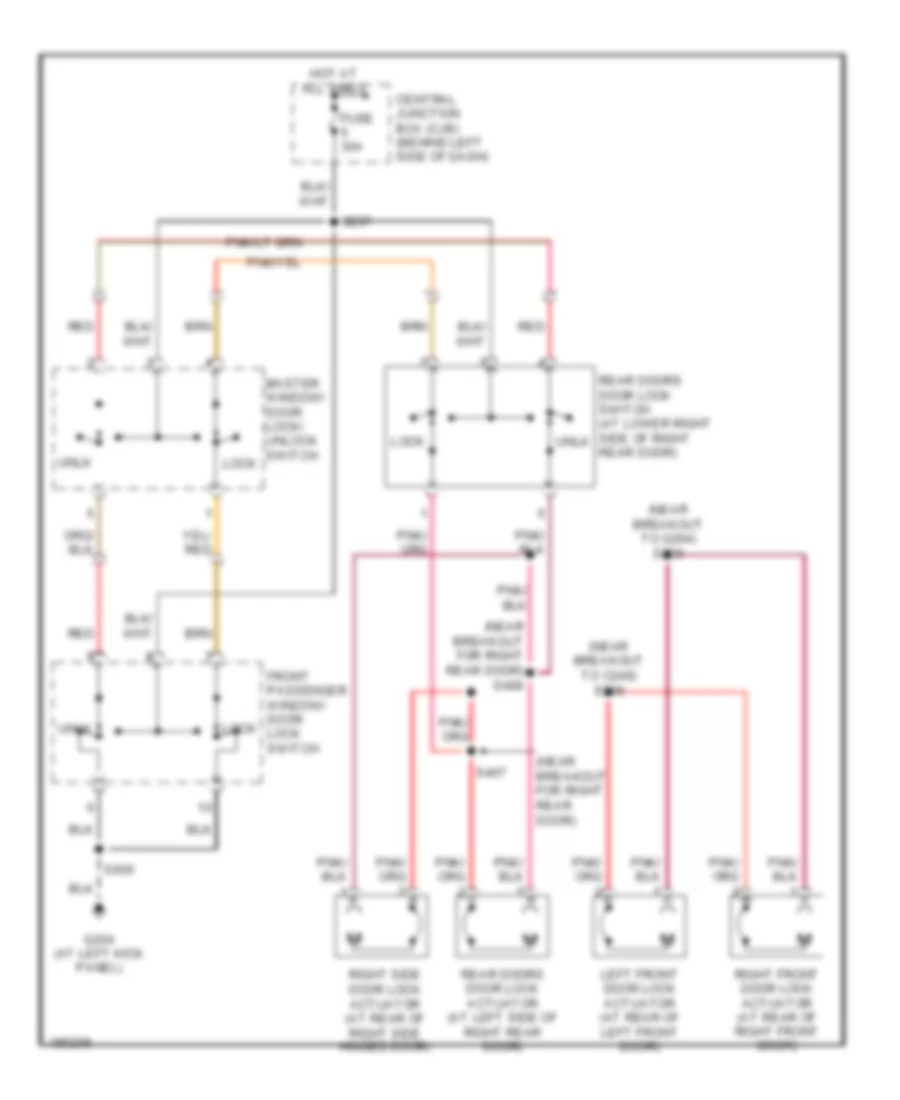
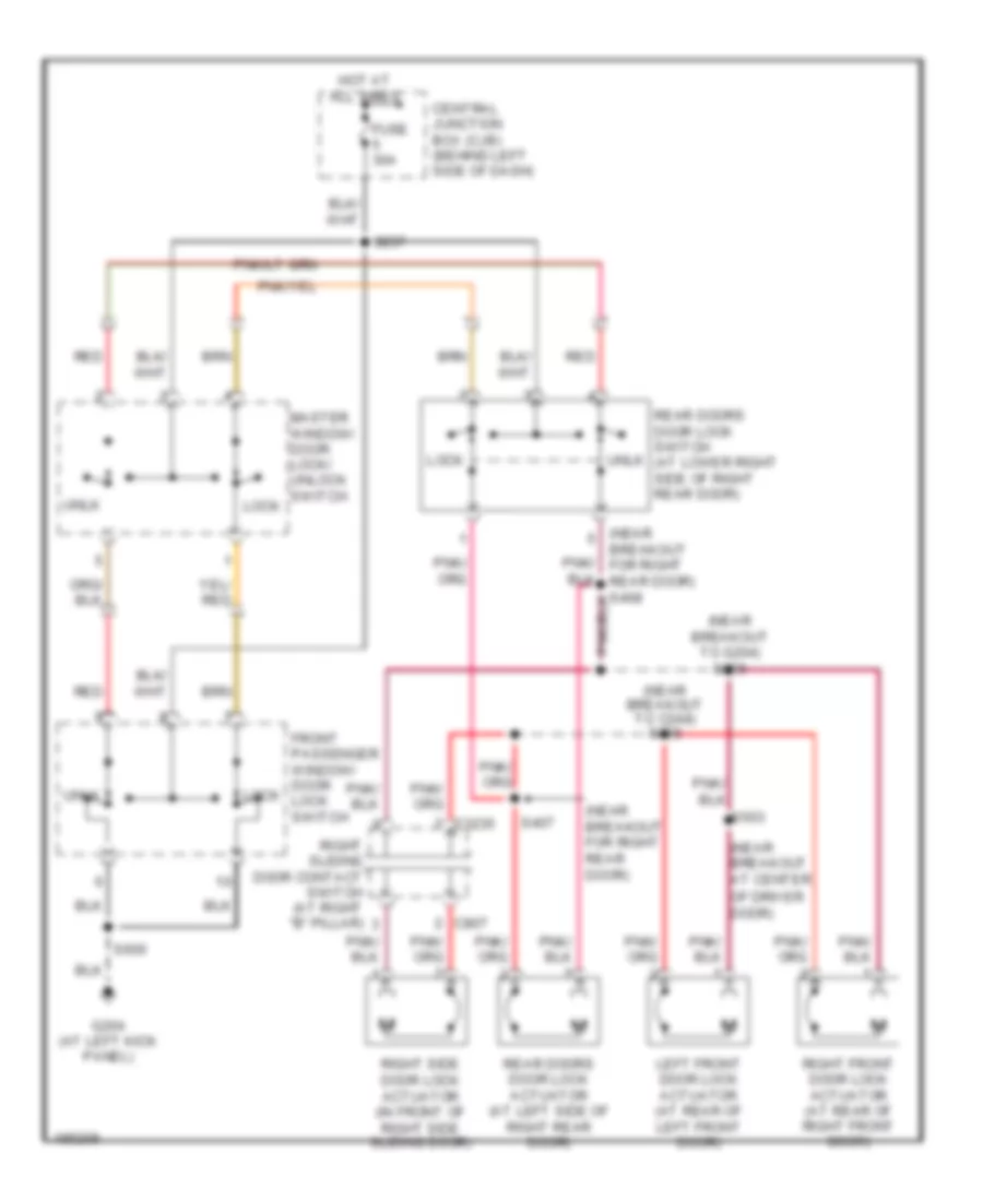
POWER DOOR LOCKS Door Lock Wiring Diagram, with Keyless Entry for Ford Econoline E150 2004 List of elements for Door Lock Wiring Diagram, with Keyless Entry for Ford Econoline E150 2004: 61 (+/-) (at left kick panel) g204 (in window regulator relay switch harness, near breakout to g204) s239 (in window regulator relay switch harness, near breakout to right kick panel) s265 (near breakout to g204) (near breakout to g204) s252 C203a C203b C220b C3235 C807 Central junction box (cjb) (behind left side of dash) Computer data lines system Dome lamp sw Door jamp sw Door lock motor Door lock sw Except cutaway Exterior lights system Front passenger window/door lock switch Fuse 10a Fuse 20a G204 (at left kick panel) G400 (at left side of vehicle rear end) Gnd Hinged side door Horn relay ctrl Horns system Hot at all times Hot in start or run Instrument cluster Interior lights system Iso bus Left front door lock actuator (at rear of left front door) Lock Master window/ door lock/unlock switch Nca Rear doors door lock actuator (except cutaway) (at left side of right rear door) Rear doors door lock switch (except cutaway) (at lower right side of right rear door) Red/pnk Right front door lock actuator (at rear of right front door) Right side door lock actuator (at rear of right side hinged door) Right side door lock actuator (in front of right side sliding door) Right sliding door ajar switch (at right "b" pillar) Right sliding door contact switch (at right "b" pillar) Rtn sig S216 S223 S233 S248 (in window regulator relay switch harness, near breakout to c248) S250 S251 S261 S414 S500 Sliding door wire Sliding side door Unlock Vbatt Vehicle security module (vsm) (at right kick panel) Vpwr Door Lock Wiring Diagram, without Keyless Entry with Hinged Side Door for Ford Econoline E150 2004 List of elements for Door Lock Wiring Diagram, without Keyless Entry with Hinged Side Door for Ford Econoline E150 2004: 21 (near breakout for right rear door) (near breakout for right rear door) s408 (near breakout to c248) s238 (near breakout to g204) s239 Central junction box (cjb) (behind left side of dash) Front passenger window/ door lock switch Fuse 30a G204 (at left kick panel) Hot at all times Left front door lock actuator (at rear of left front door) Lock Master window/ door lock/ unlock switch Rear doors door lock actuator (at left side of right rear door) Rear doors door lock switch (at lower right side of right rear door) Red Right front door lock actuator (at rear of right front door) Right side door lock actuator (at rear of right side hinged door) S237 S407 S600 Unlk Door Lock Wiring Diagram, without Keyless Entry with Sliding Side Door for Ford Econoline E150 2004 List of elements for Door Lock Wiring Diagram, without Keyless Entry with Sliding Side Door for Ford Econoline E150 2004: 27 (near (near breakout at center (near breakout for right rear door) (near breakout to c248) s238 (near breakout to g204) s239 C3235 C807 Central junction box (cjb) (behind left side of dash) Front passenger window/ door lock switch Fuse 30a G204 (at left kick panel) Hot at all times Left front door lock actuator (at rear of left front door) Lock Master window/ door lock/ unlock switch Of driver door) Rear doors door lock actuator (at left side of right rear door) Rear doors door lock switch (at lower right side of right rear door) Red Right front door lock actuator (at rear of right front door) Right side door lock actuator (in front of right side sliding door) Right sliding door contact switch (at right "b" pillar) S237 S407 S503 S600 Unlk
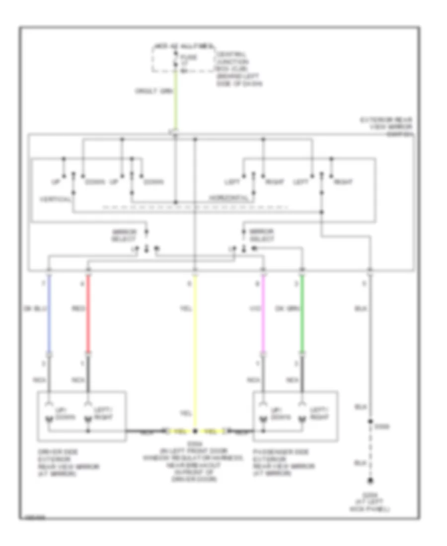
POWER MIRRORS Power Mirrors Wiring Diagram for Ford Econoline E150 2004 List of elements for Power Mirrors Wiring Diagram for Ford Econoline E150 2004: 20 Central junction box (cjb) (behind left side of dash) Down Driver side exterior rear view mirror (at mirror) Exterior rear view mirror switch Fuse 5a G204 (at left kick panel) Horizontal Hot at all times Left Left/ right Left/ right m Mirror select Nca Passenger side exterior rear view mirror (at mirror) Red Right S500 S504 (in left front door window regulator harness, near breakout in front of driver door) Up/ down m Vertical
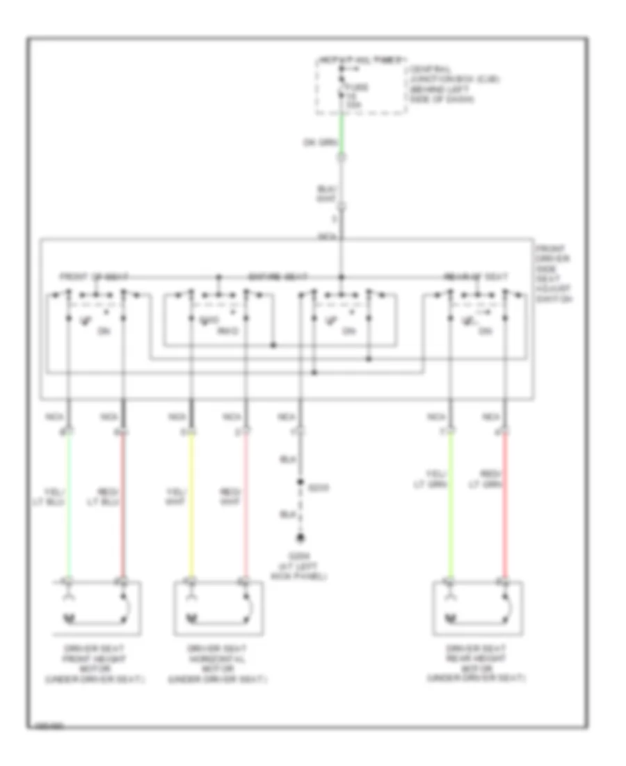
POWER SEATS Power Seats Wiring Diagram for Ford Econoline E150 2004 List of elements for Power Seats Wiring Diagram for Ford Econoline E150 2004: 15 Central junction box (cjb) (behind left side of dash) Driver seat front height motor (under driver seat) Driver seat horizontal motor (under driver seat) Driver seat rear height motor (under driver seat) Entire seat Front driver side seat adjust switch Front of seat Fuse 30a Fwd G204 (at left kick panel) Hot at all times Nca Rear of seat Rwd S235
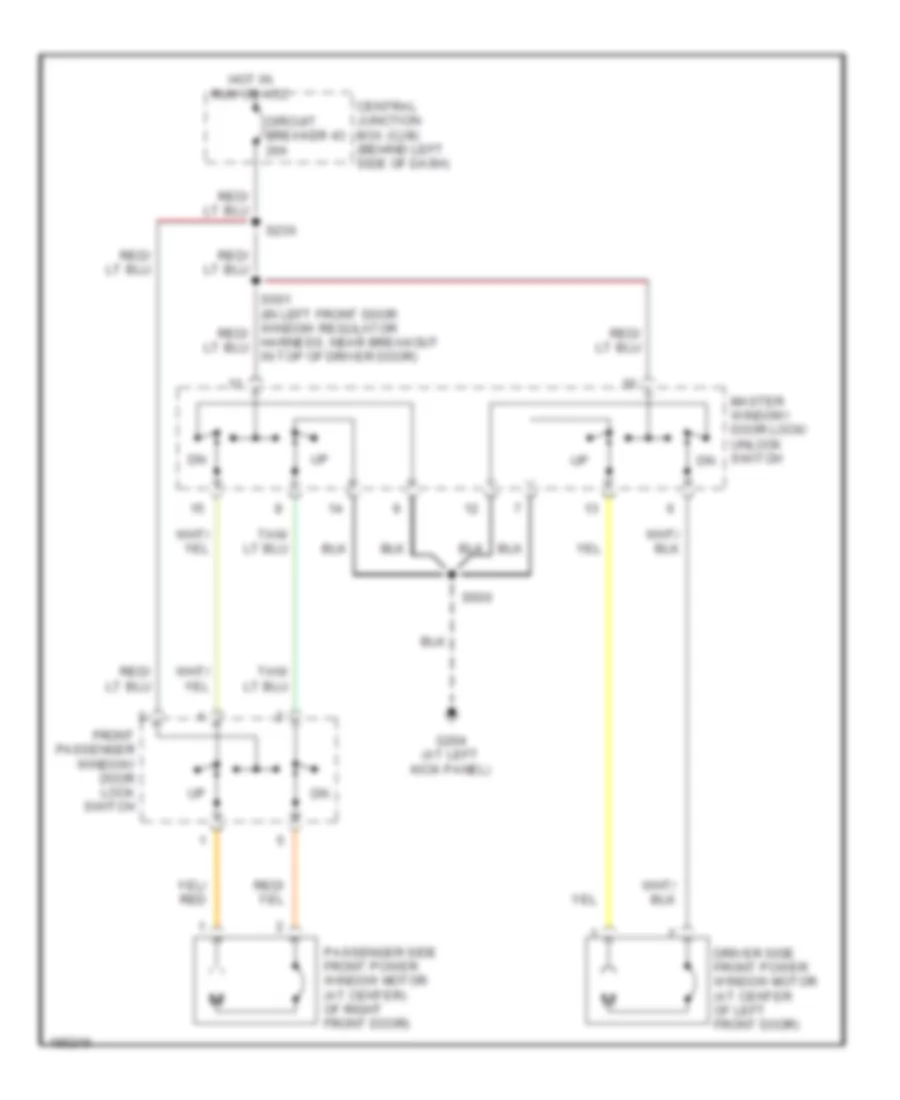
POWER WINDOWS Power Windows Wiring Diagram for Ford Econoline E150 2004 List of elements for Power Windows Wiring Diagram for Ford Econoline E150 2004: 11 Central junction box (cjb) (behind left side of dash) Circuit breaker 43 20a Driver side front power window motor (at center of left front door) Front passenger window/ door lock switch G204 (at left kick panel) Harness, near breakout in top of driver door) Hot in run or acc Master window/ door lock/ unlock switch Passenger side front power window motor (at center) of right front door) S236 S500
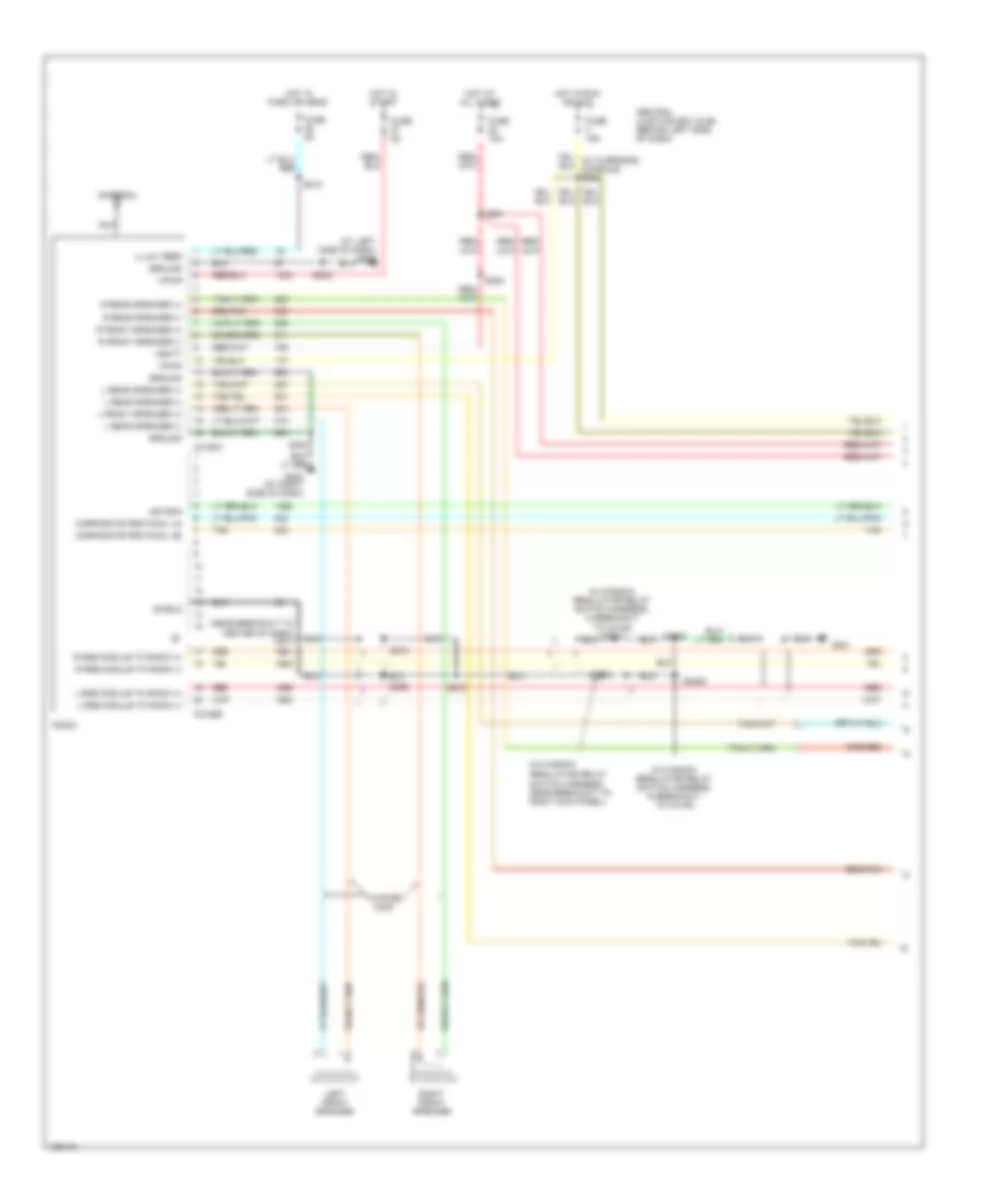
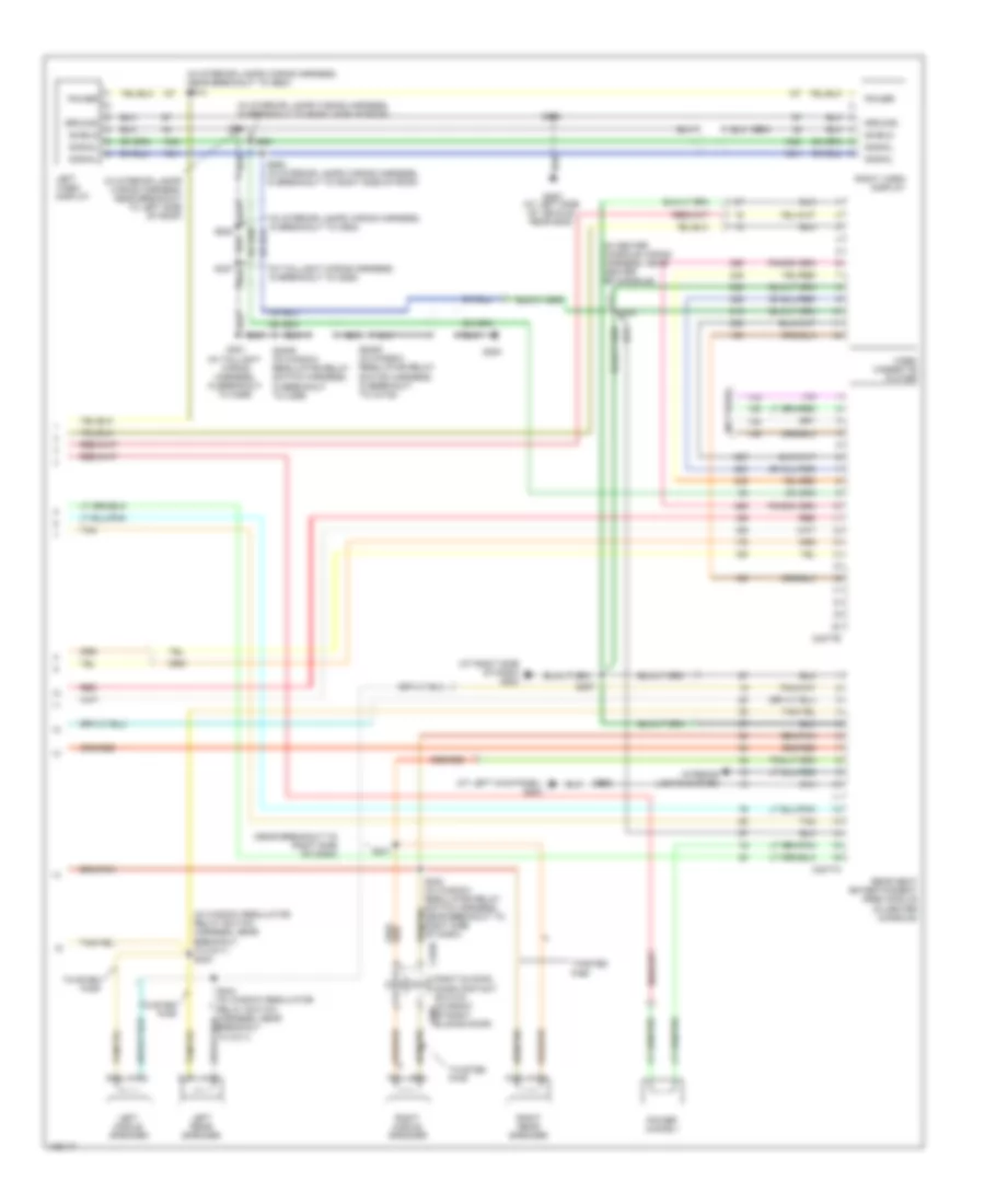
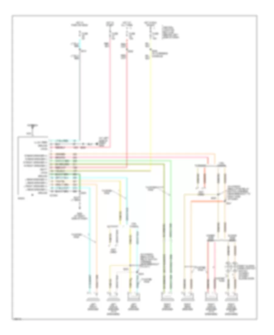
RADIO Radio Wiring Diagram, with Rear Entertainment (1 of 2) for Ford Econoline E150 2004 List of elements for Radio Wiring Diagram, with Rear Entertainment (1 of 2) for Ford Econoline E150 2004: 55 (at left side of dash) g202 (in window regulator relay (in window regulator relay switch harness, in breakout to c3138) (in window regulator relay switch harness, in breakout to c3138) s2007 (near breakout to center of dash) s274 Antenna Asyson C2188a C2188b Central junction box (cjb) (behind left side of dash) Corporate protocol (a) Corporate protocol (b) Fuse 15a Fuse 5a G200 (at right side of dash) G301 Ground Hot at all times Hot in park or head Hot in run or acc Hot in start Illum, feed L front speaker (+) L rear speaker (+) L rear speaker (-) L rse module to radio (+) L rse module to radio (-) Left front speaker Nca R front speaker (+) R front speaker (-) R rear speaker (+) R rear speaker (-) R rse module to radio (+) R rse module to radio (-) Radio Red Right front speaker S2003 S2006 S2008 S202 S204 S205 S212 S222 S272 S273 S291 Shield Switch harness, near breakout to right kick panel) Tan Twisted pair Vbatt Vpwr Radio Wiring Diagram, with Rear Entertainment (2 of 2) for Ford Econoline E150 2004 List of elements for Radio Wiring Diagram, with Rear Entertainment (2 of 2) for Ford Econoline E150 2004: 49 (at left kick panel) g204 (at right side of dash) g200 (in center console wiring harness, near center of console) (in interior lamps wiring harness, in breakout to c983) (in interior lamps wiring harness, in breakout to right side of roof) (in interior lamps wiring harness, near breakout to left side of roof) (in interior lamps wiring harness, near breakout to c925) (in taillight wiring harness, in breakout to c925) (in window regulator relay switch harness, near breakout to c311) s243 (near breakout to right side of dash) (not used) C3077a C3077b C3235 G300 G400 (at left side of vehicle rear end) Ground Interior lights system Left middle speaker Left rear speaker Left video display Power Power choke 1 Rear seat entertainment (rse) module (in center console) Red Right middle speaker Right rear speaker Right sliding door contact switch (in front c807 of right sliding door) Right video display S2005 (in window regulator relay switch harness, in breakout to c3138) S2009 (in window regulator relay switch harness, in breakout to c299) S235 S240 (in window regulator relay switch harness, near breakout to right side of dash) S241 S244 (in window regulator relay switch harness, near breakout to c311) S297 S323 S381 (in taillight wiring harness, in breakout to c299) S914 S915 S916 S920 (in interior lamps wiring harness, in breakout to right side of roof) S921 S941 Shield Signal Tan Twisted pair Video cassette player Radio Wiring Diagram, without Rear Entertainment for Ford Econoline E150 2004 List of elements for Radio Wiring Diagram, without Rear Entertainment for Ford Econoline E150 2004: 48 (at left side of dash) g202 (in window regulator relay switch harness, near breakout to c311) (in window regulator relay switch harness, near breakout to right side of dash) (not used) Antenna C2188a Central junction box (cjb) (behind left side of dash) Cutaway Fuse 15a Fuse 5a G200 (at right side of dash) Ground Hinged side door Hot at all times Hot in park or head Hot in run or acc Hot in start Illum, feed L front speaker (+) L rear speaker (+) L rear speaker (-) Left front speaker Left middle speaker (w/ 6 speakers) Left rear speaker Nca R front speaker (+) R front speaker (-) R rear speaker (+) R rear speaker (-) Radio Right front speaker Right middle speaker (w/ 6 speakers) Right rear speaker Right sliding door contact switch (in front of right sliding door) S202 S204 S205 S212 S240 S241 S243 S244 S245 (w/ overhead console) Sliding side door Twisted pair Van, wagon Vbatt Vpwr
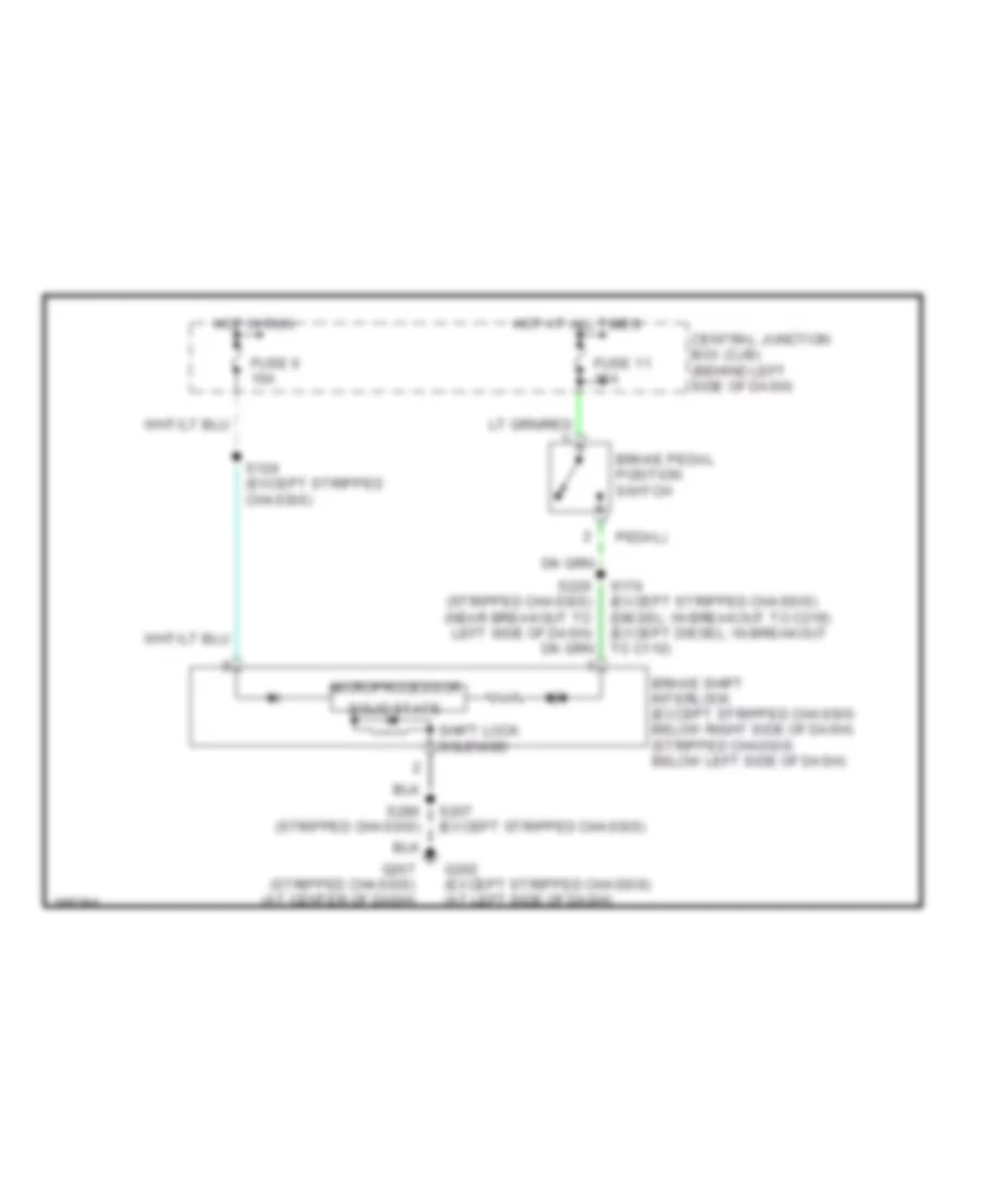
SHIFT INTERLOCK Shift Interlock Wiring Diagram for Ford Econoline E150 2004 List of elements for Shift Interlock Wiring Diagram for Ford Econoline E150 2004: 17 Brake pedal position switch Brake shift interlock (except stripped chassis: below right side of dash) (stripped chassis: below left side of dash) Central junction box (cjb) (behind left side of dash) Fuse 11 15a Fuse 6 10a G202 (except stripped chassis) (at left side of dash) G207 (stripped chassis) (at center of dash) Hot at all times Hot in run Microprocessor Pedal) S124 (except stripped chassis) S207 (except stripped chassis) S220 (stripped chassis) (near breakout to left side of dash) S286 (stripped chassis) Shift lock solenoid Solid state
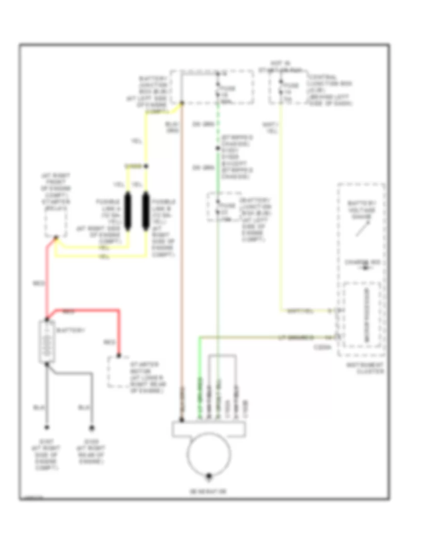
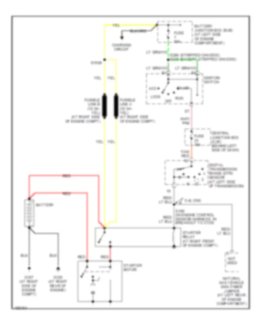
STARTING/CHARGING Charging Wiring Diagram for Ford Econoline E150 2004 List of elements for Charging Wiring Diagram for Ford Econoline E150 2004: 22 (at right front of engine compt) starter relay (stripped chassis) s1031 s1028 (except (stripped chassis) Battery Battery junction box (bjb) (at left side of engine compt) Battery voltage gauge C102a C102b C220a Central junction box (cjb) (behind left side of dash) Charge ind Fuse 10a Fuse 5a Fuse 60a G107 (at right side of engine compt) G120 (at right rear of engine) Generator Hot in start or run Instrument cluster Microprocessor Red S1008 Starter motor (at lower right rear of engine) Starting Wiring Diagram for Ford Econoline E150 2004 List of elements for Starting Wiring Diagram for Ford Econoline E150 2004: 25 (stripped chassis) (except stripped chassis) 5.4l cng Acc Battery Battery junction box (bjb) (at left side of engine compartment) Central junction box (cjb) (behind left side of dash) Charging circuit Digital transmission range (dtr) Fuse 10a Fuse 60a G107 (at right side of engine compt) G120 (at right rear of engine) Ignition switch Lock Natural gas vehicle (ngv)timer jumper (at left rear of engine compartment) Not used Off Red Run S1008 Sensor (at left side of transmission) Start Starter motor Starter relay (at right front of engine compt) Tan/ red
SUPPLEMENTAL RESTRAINTS Supplemental Restraints Wiring Diagram for Ford Econoline E150 2004 List of elements for Supplemental Restraints Wiring Diagram for Ford Econoline E150 2004: 38 (behind left side of dash) air bag sliding contact (in window regulator relay switch harness, near breakout to c311) s235 Air bag ind ground Air bag indicator C218a C220a C220b C310a C310b Center air bag sensor (at front center of engine compartment) Central junction box (cjb) (behind left side of dash) Computer data lines system Driver air bag unit Driver safety belt retractor pretensioner (under driver seat) Except stripped chassis Feed Fuse 10a Fuse 5a G201 (under driver seat) G204 (at left kick panel) Hot in start or run Instrument cluster Iso vbatt Microprocessor Nca Nca pretensioner feed Nca pretensioner rtn nca ground nca switch input Passenger air bag module (behind right side of dash) Passenger safety belt retractor pretensioner (under passenger seat) Pretensioner nca Pretensioner return Restraints control module (under driver seat) Safety belt indicator Shorting bar Shorting bar engaged when harness connector is disconnected from module (shorting bars are connected between following pins: 1-2, 3-4 & 15-16 conn. c310a) Sig rtn Tone out Vref
TRANSMISSION
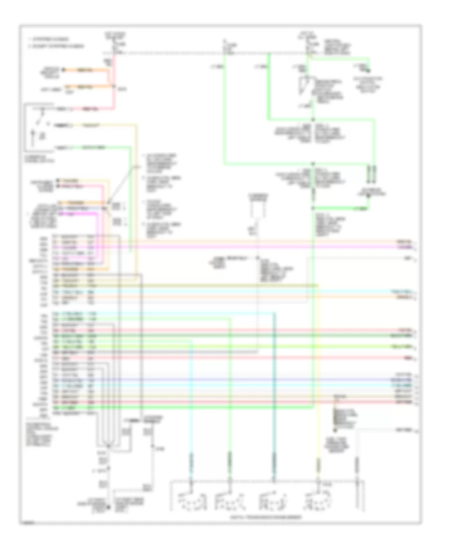
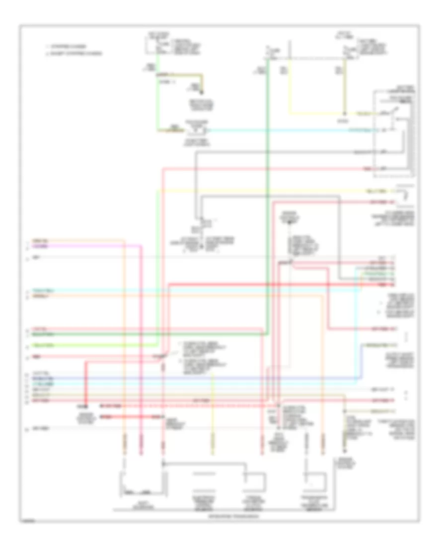
4.6L 4.6L, A/T Wiring Diagram (1 of 2) for Ford Econoline E150 2004 List of elements for 4.6L, A/T Wiring Diagram (1 of 2) for Ford Econoline E150 2004: 68 (at right rear side of engine compt) g116 (at right side of engine compt) g107 (eng ctrl sens harn, near breakout to c1033) (in eng ctrl sens harn, near breakout to c237) (in main (in window reg rly sw harn, near breakout to steering column) (main wiring harn, near breakout to left side of dash) (not used) c237 (window reg rly sw harn, rear breakout to c248) Bpp Brake pedal position switch (on bracket, above brake pedal) Central junction box (behind left side of dash) Cht Data (+) Data (-) Data link connector (behind left side of dash, below left side of dash) Digital transmission range sensor Epc Except stripped chassis Exterior lights system Fuel tank pressure transducer sensor Fuse 10a Fuse 15a Gen data Gnd Hot at all times Hot in run or start Instrument cluster system Kapwr Maf Multifunction switch, deavtiator switch Nca Od off Oss Others Overdrive cancel switch Overhead console Powertrain control module (pcm) (in eng compt, on left side of firewall) Pwr in Red S134 (eng ctrl sens harn, near breakout to rear of eng compt) S135 (eng ctrl sens harn, near breakout to left rear of eng compt) S138 S140 S169 S172 S216 S220 s224 (window reg rly sw harn, rear breakout to c237) S228 s182 S269 s184 Sig rtn Speed control servo Ssa Ssb Stripped chassis Tcc Tcil Tcs Tft Tps Tr1 Tr2 Tr3 Tr4 Vehicle security module Vref Vss Wiring harn, near breakout to left side of dash) 4.6L, A/T Wiring Diagram (2 of 2) for Ford Econoline E150 2004 List of elements for 4.6L, A/T Wiring Diagram (2 of 2) for Ford Econoline E150 2004: 47 (at right rear side of engine compt) g116 (at right side of engine compt) g107 (eng ctrl harn, near breakout to left rear of eng compt) (in battery junction box) (in eng ctrl sens (in eng ctrl sens & fuel charging wiring harn, at left center of eng) (in headlamp lead wiring harn, in breakout to c1046) (near breakout at rear (top center of engine compt) 4r70e/4r75e transmission Battery junction box Battery junction box (left side of engine compt) Central junction box (behind left side of dash) Cylinder head temperature sensor (on top front of left cylinder head) Electronic pressure control solenoid Engine controls system Except stripped chassis Fuse 10a Fuse 30a Harn, near breakout to center of eng compt) Harn, near breakout to left rear of eng compt) Hot at all times Hot in run or start Ignition coil, radio noise capacitor Mass airflow (maf) sensor (at center of engine compt) Of eng) Output shaft speed sensor (left side of transmission) Pcm power diode Pcm power relay Red S100 S102 (near breakout at rear S1033 S1065 S127 S136 S140 S142 S157 S158 Shift solenoids Ssa Ssb Stripped chassis Throttle position sensor (tps) (on top of engine, near air intake) Torque converter clutch solenoid Transmission fluid temperature sensor
5.4L 5.4L, A/T Wiring Diagram, with 4R100 Transmission (1 of 2) for Ford Econoline E150 2004 List of elements for 5.4L, A/T Wiring Diagram, with 4R100 Transmission (1 of 2) for Ford Econoline E150 2004: 74 (1) (2) (at right rear side of engine compt) g116 (at right side of engine compt) g107 (eng ctrl sens harn, near breakout to c1033) (in eng ctrl sens (in main wiring harn, near breakout to left side of dash) (in window reg rly sw harn, near breakout to steering column) (not used) c237 (window reg rly sw harn, rear breakout to c237) (window reg rly sw harn, rear breakout to c248) 6.8l Bpp Brake pedal position switch (on bracket, above brake pedal) Ccs Central junction box (behind left side of dash) Cht Data (+) Data (-) Data link connector (behind left side of dash, below left side of dash) Digital transmission range sensor Epc Except stripped chassis Exterior lights system Fuel tank pressure transducer sensor Fuse 10a Fuse 15a Gen data Gnd Harn, near breakout to c237) Hot at all times Hot in run or start Instrument cluster system Kapwr Maf Multifunction switch, deavtiator switch Nca Od off Oss Others Overdrive cancel switch Overhead console Powertrain control module (pcm) (in eng compt, on left side of firewall) Pwr in Red S134 (eng ctrl sens harn, near breakout to rear of eng compt) S135 (eng ctrl sens harn, near breakout to left rear of eng compt) S138 S140 S169 S172 S216 S224 s220 (main wiring harn, near breakout to left side of dash) S228 s182 S231 s283 (main wiring harn, in breakout to left side of dash) S269 s184 Sig rtn Speed control servo Ssa Ssb Stripped chassis Tcc Tcil Tcs Tft Tps Tr1 Tr2 Tr3 Tr4 Tss Vehicle security module Vref Vss 5.4L, A/T Wiring Diagram, with 4R100 Transmission (2 of 2) for Ford Econoline E150 2004 List of elements for 5.4L, A/T Wiring Diagram, with 4R100 Transmission (2 of 2) for Ford Econoline E150 2004: 48 (at right rear side of engine compt) g116 (at right side of engine compt) g107 (eng ctrl harn, near breakout to left rear of eng compt) s136 (in battery junction box) (in eng ctrl (in eng ctrl sens & fuel charging warning harn, at left center of eng) (in eng ctrl sens harn, near breakout to left rear of eng compt) (in headlamp lead wiring harn, in breakout to c1046) (in trans ctrl selector neutral sw, near breakout at top of transmission) (in trans ctrl selector neutral sw: w/o ngv: near breakout at rear of eng, w/ ngv: near breakout at right side of transmission) (top center of engine compt) 4r100 transmission Battery junction box Battery junction box (left side of engine compt) Central junction box (behind left side of dash) Coast clutch solenoid Cylinder head temperature sensor (on top front of left cylinder head) Electronic pressure control solenoid Engine controls system Except stripped chassis Fuse 10a Fuse 30a Gasoline Hot at all times Hot in run or start Ignition coil, radio noise capacitor Mass airflow (maf) sensor (at center of engine compt) Natural gas vehicle Output shaft speed sensor (left side of transmission) Pcm power diode Pcm power relay Red S100 S102 S1033 S127 s1065 S140 S142 S157 S158 Sens harn, near breakout to center of eng compt) Shift solenoid a Shift solenoid b Stripped chassis Throttle position sensor (tps) (on top of engine, near air intake) Torque converter clutch solenoid Transmission fluid temperature sensor Turbine shaft sensor (at left side of transmission) 5.4L, A/T Wiring Diagram, with 4R70E/4R75E (1 of 2) for Ford Econoline E150 2004 List of elements for 5.4L, A/T Wiring Diagram, with 4R70E/4R75E (1 of 2) for Ford Econoline E150 2004: 68 (at right rear side of engine compt) g116 (at right side of engine compt) g107 (eng ctrl sens harn, near breakout to c1033) (in eng ctrl sens harn, near breakout to c237) (in main (in window reg rly sw harn, near breakout to steering column) (main wiring harn, near breakout to left side of dash) (not used) c237 (window reg rly sw harn, rear breakout to c248) Bpp Brake pedal position switch (on bracket, above brake pedal) Central junction box (behind left side of dash) Cht Data (+) Data (-) Data link connector (behind left side of dash, below left side of dash) Digital transmission range sensor Epc Except stripped chassis Exterior lights system Fuel tank pressure transducer sensor Fuse 10a Fuse 15a Gen data Gnd Hot at all times Hot in run or start Instrument cluster system Kapwr Maf Multifunction switch, deavtiator switch Nca Od off Oss Others Overdrive cancel switch Overhead console Powertrain control module (pcm) (in eng compt, on left side of firewall) Pwr in Red S134 (eng ctrl sens harn, near breakout to rear of eng compt) S135 (eng ctrl sens harn, near breakout to left rear of eng compt) S138 S140 S169 S172 S216 S220 s224 (window reg rly sw harn, rear breakout to c237) S228 s182 S269 s184 Sig rtn Speed control servo Ssa Ssb Stripped chassis Tcc Tcil Tcs Tft Tps Tr1 Tr2 Tr3 Tr4 Vehicle security module Vref Vss Wiring harn, near breakout to left side of dash) 5.4L, A/T Wiring Diagram, with 4R70E/4R75E (2 of 2) for Ford Econoline E150 2004 List of elements for 5.4L, A/T Wiring Diagram, with 4R70E/4R75E (2 of 2) for Ford Econoline E150 2004: 47 (at right rear side of engine compt) g116 (at right side of engine compt) g107 (eng ctrl harn, near breakout to left rear of eng compt) (in battery junction box) (in eng ctrl sens (in eng ctrl sens & fuel charging wiring harn, at left center of eng) (in headlamp lead wiring harn, in breakout to c1046) (near breakout at rear (top center of engine compt) 4r70e/4r75e transmission Battery junction box Battery junction box (left side of engine compt) Central junction box (behind left side of dash) Cylinder head temperature sensor (on top front of left cylinder head) Electronic pressure control solenoid Engine controls system Except stripped chassis Fuse 10a Fuse 30a Harn, near breakout to center of eng compt) Harn, near breakout to left rear of eng compt) Hot at all times Hot in run or start Ignition coil, radio noise capacitor Mass airflow (maf) sensor (at center of engine compt) Of eng) Output shaft speed sensor (left side of transmission) Pcm power diode Pcm power relay Red S100 S102 (near breakout at rear S1033 S1065 S127 S136 S140 S142 S157 S158 Shift solenoids Ssa Ssb Stripped chassis Throttle position sensor (tps) (on top of engine, near air intake) Torque converter clutch solenoid Transmission fluid temperature sensor
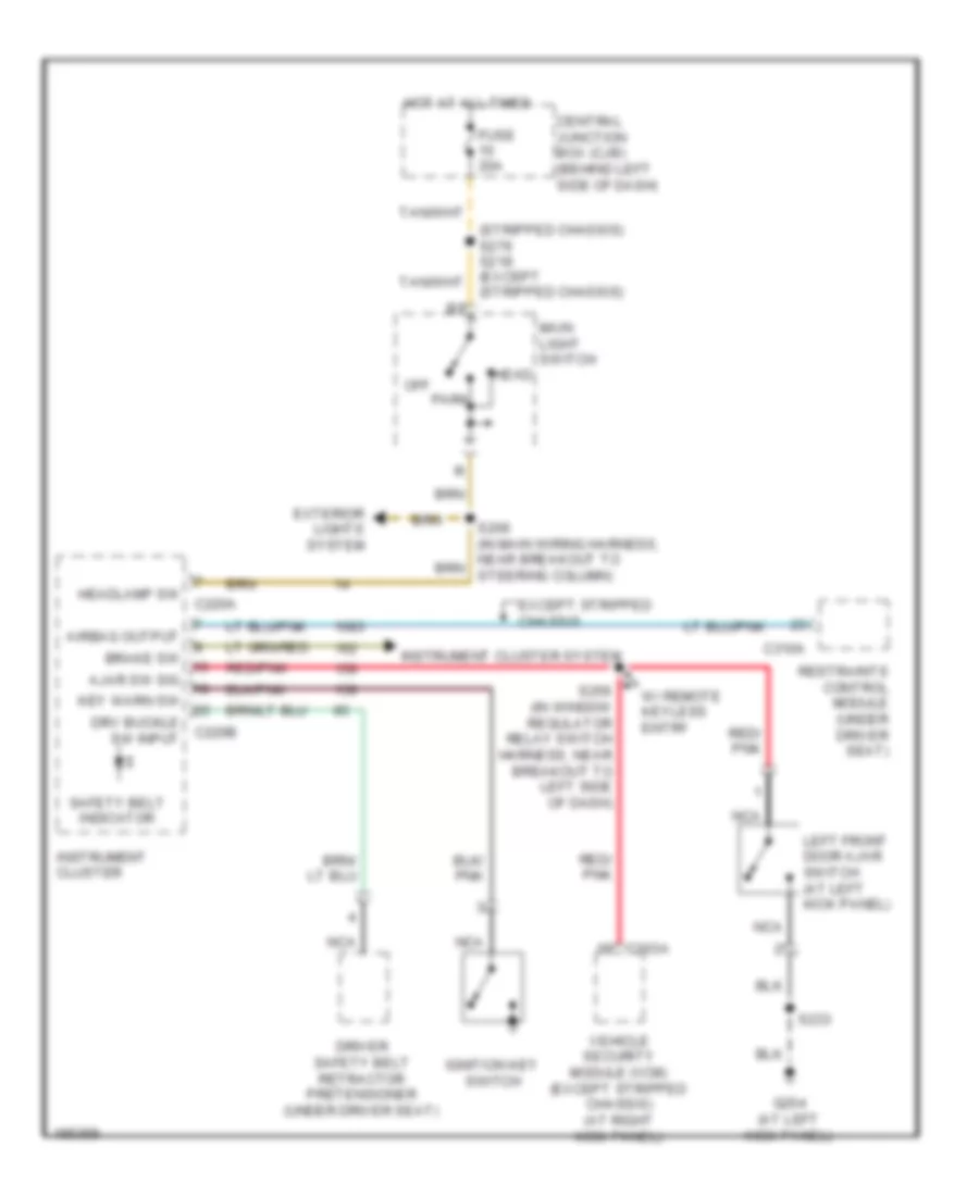
WARNING SYSTEMS Warning Systems Wiring Diagram for Ford Econoline E150 2004 List of elements for Warning Systems Wiring Diagram for Ford Econoline E150 2004: 35 (stripped chassis) Airbag output Ajar sw sig Brake sw C203a C220a C220b C310a Central junction box (cjb) (behind left side of dash) Driver safety belt retractor pretensioner (under driver seat) Drv buckle sw input Except stripped chassis Exterior lights system Fuse 20a G204 (at left kick panel) Head Headlamp sw Hot at all times Ignition key switch Instrument cluster Instrument cluster system Key warn sw Left front door ajar switch (at left kick panel) Main light switch Nca Off Park Red/ pnk Red/pnk Restraints control module (under driver seat) S233 S256 (in window regulator relay switch harness, near breakout to left side of dash) Safety belt indicator Vehicle security module (vcm) (except stripped chassis) (at right kick panel) W/ remote keyless entry
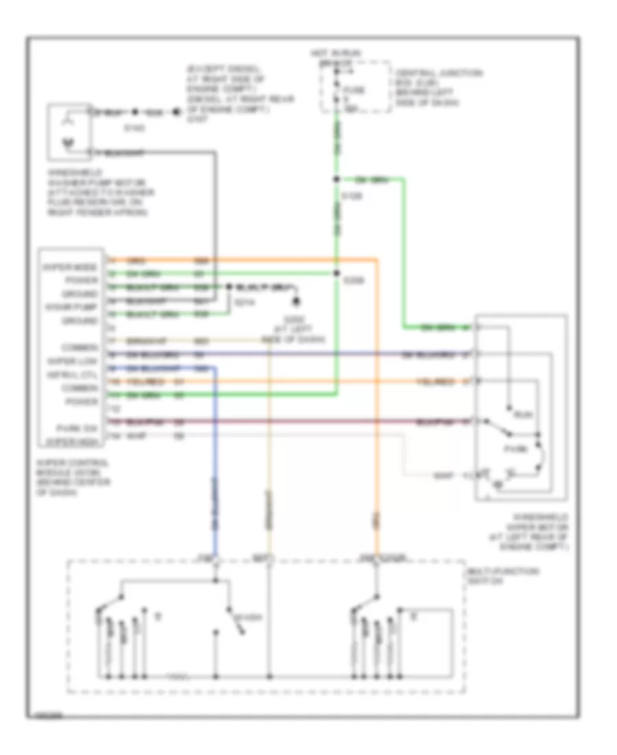
WIPER/WASHER Wiper/Washer Wiring Diagram for Ford Econoline E150 2004 List of elements for Wiper/Washer Wiring Diagram for Ford Econoline E150 2004: 28 (except diesel: at right side of engine compt) (diesel: at right rear of engine compt) g107 C202b Central junction box (cjb) (behind left side of dash) Common Fuse 30a G202 (at left side of dash) Ground Hot in run or acc Intrvl ctl Max Min Multi-function switch Off Park Park sw Power Run S143 S208 S214 Wash Windshield washer pump motor (attached to washer fluid reservoir, on right fender apron) Windshield wiper motor (at left rear of engine compt) Wiper control module (wcm) (behind center of dash) Wiper high Wiper low Wiper mode Wshr pump