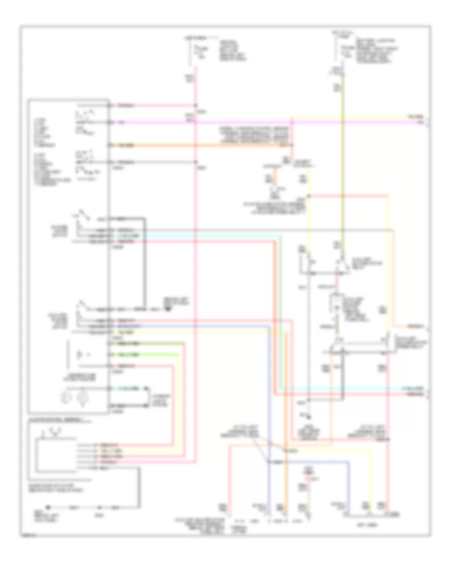
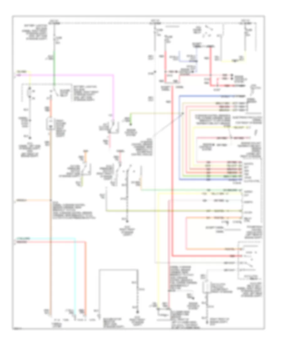
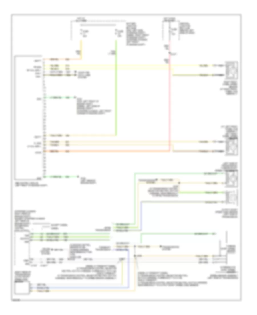
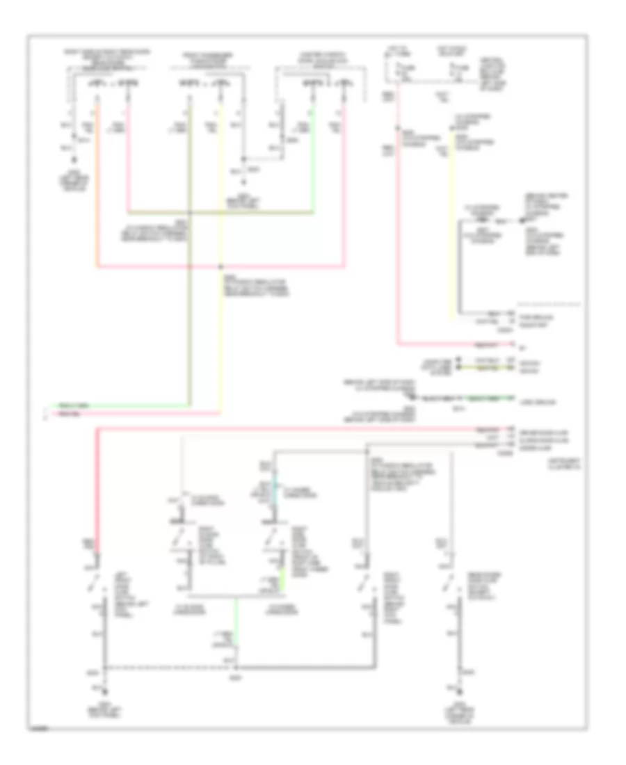
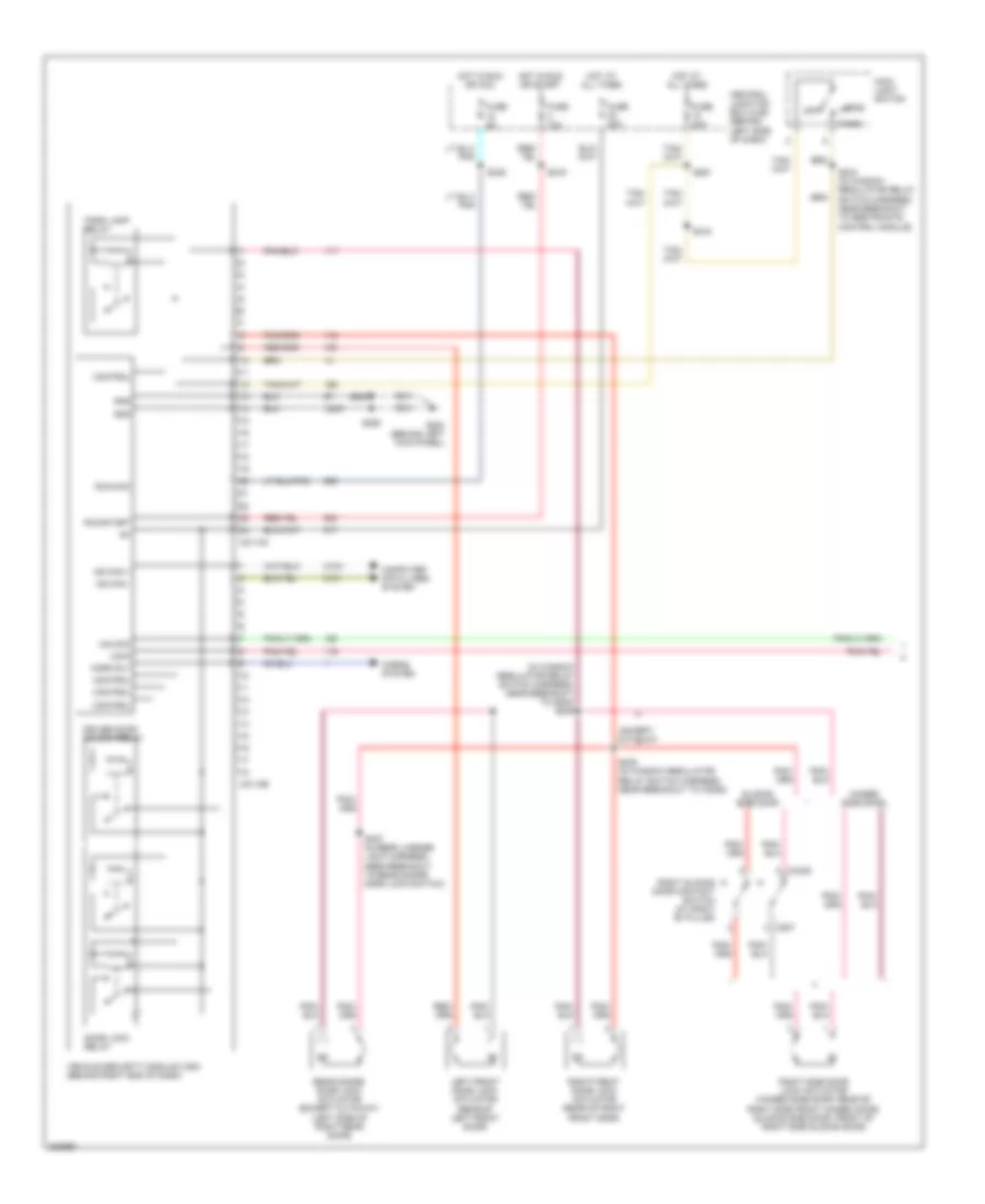
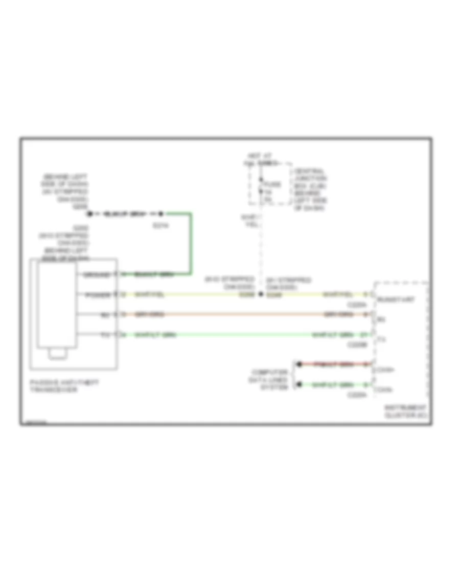
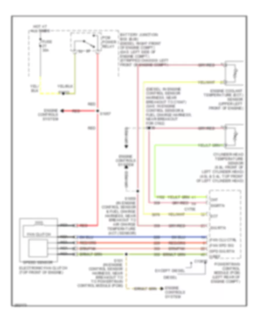
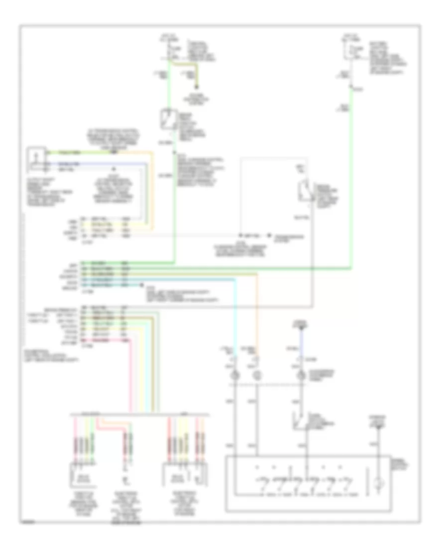
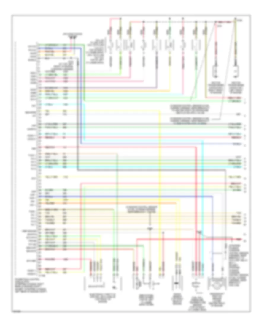
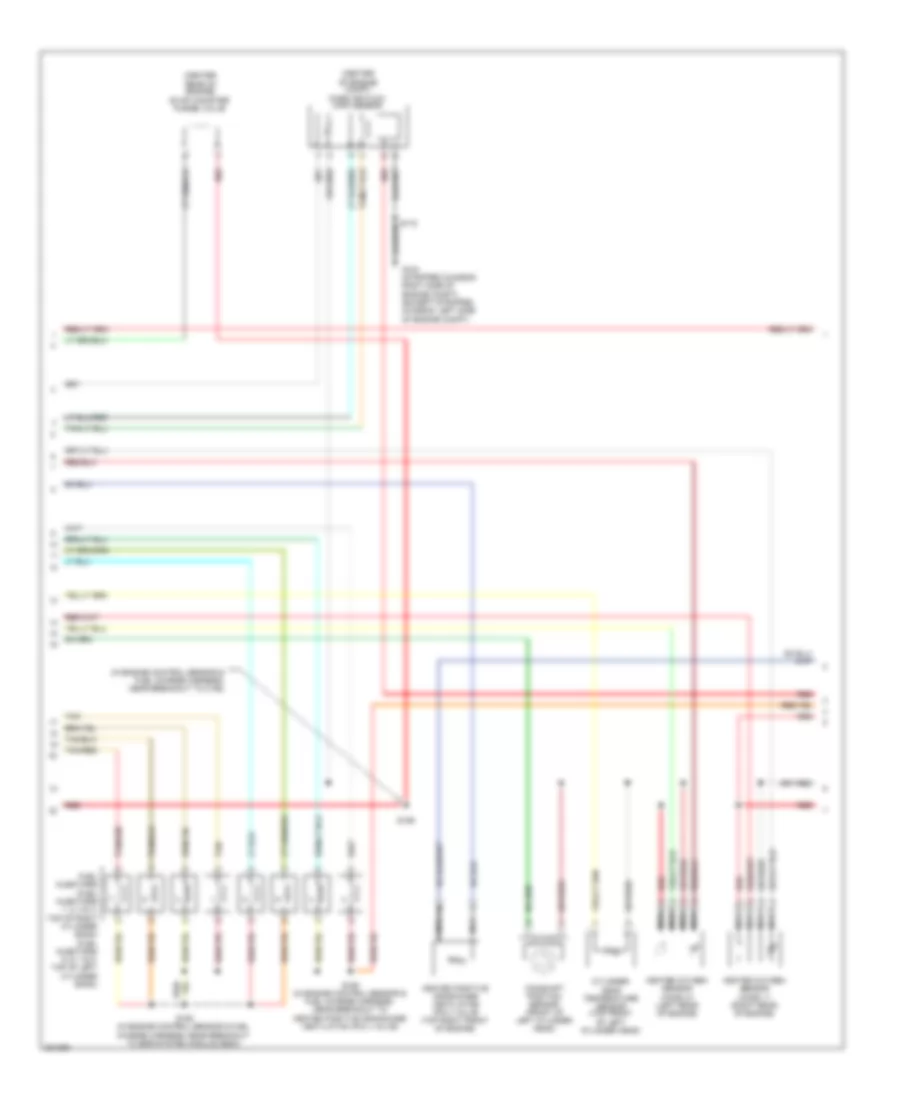
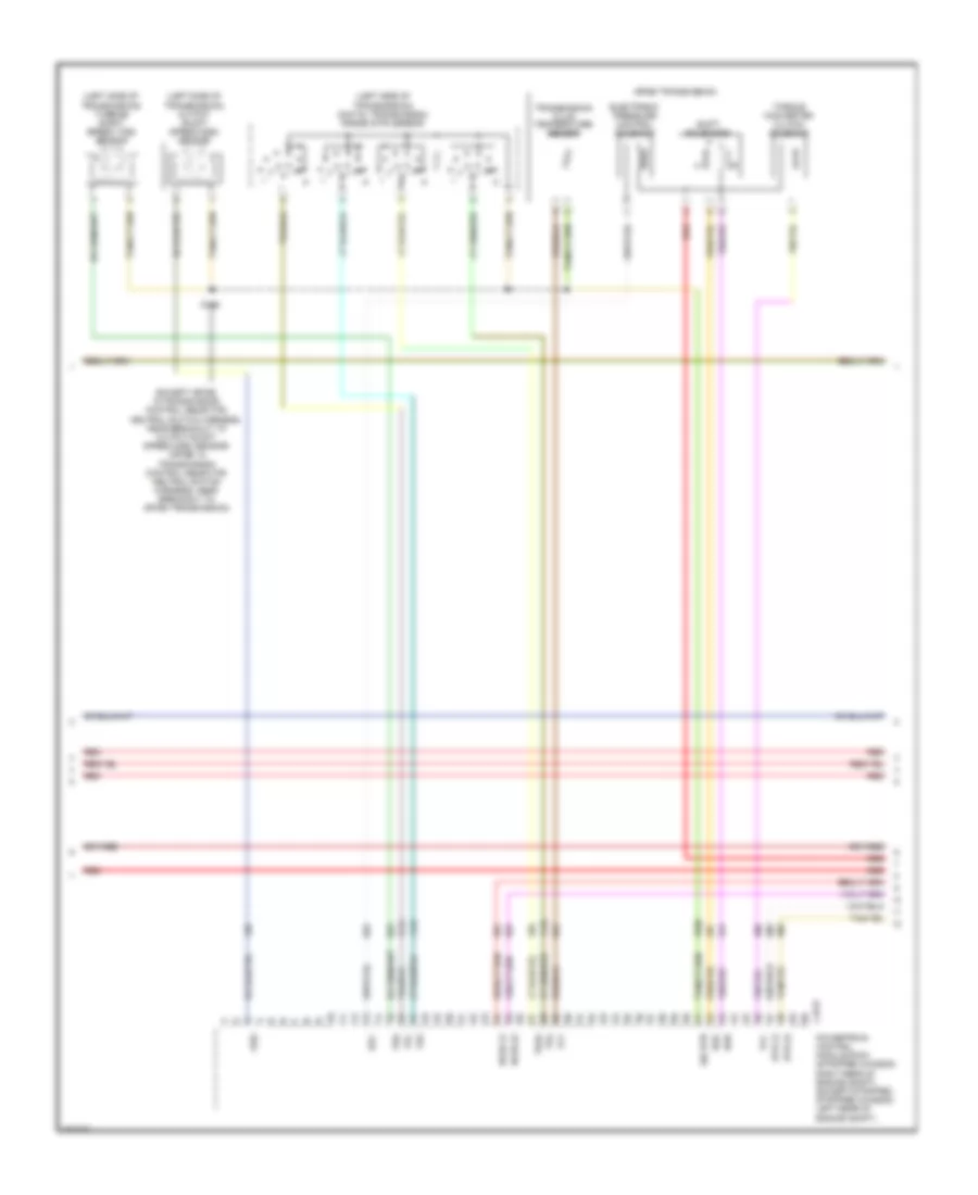
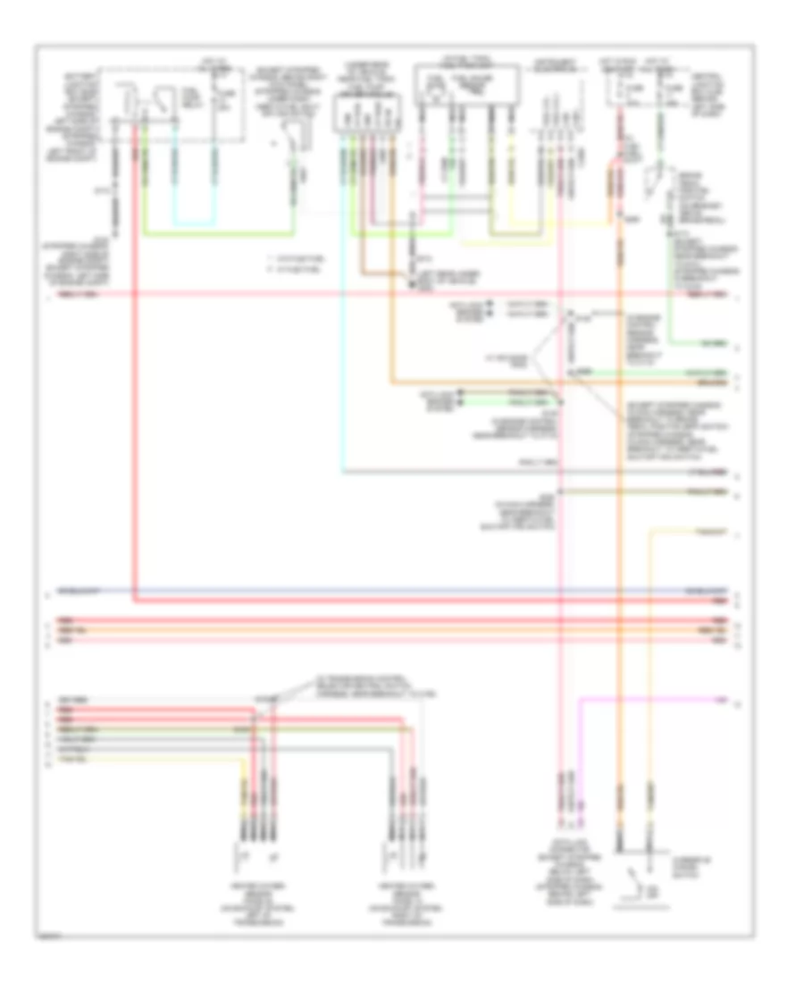
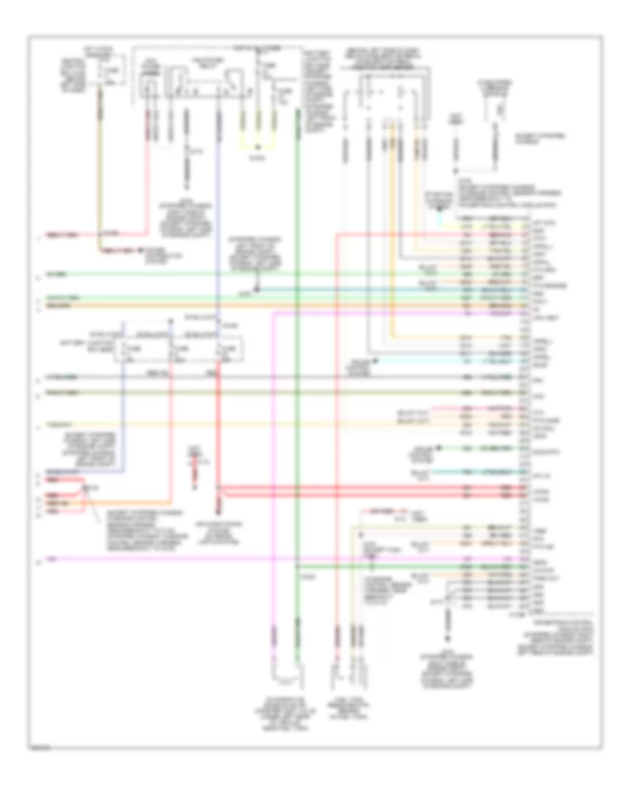
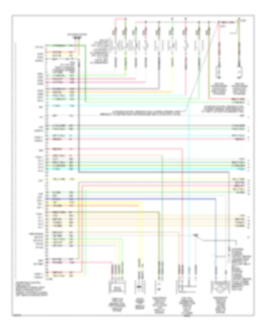
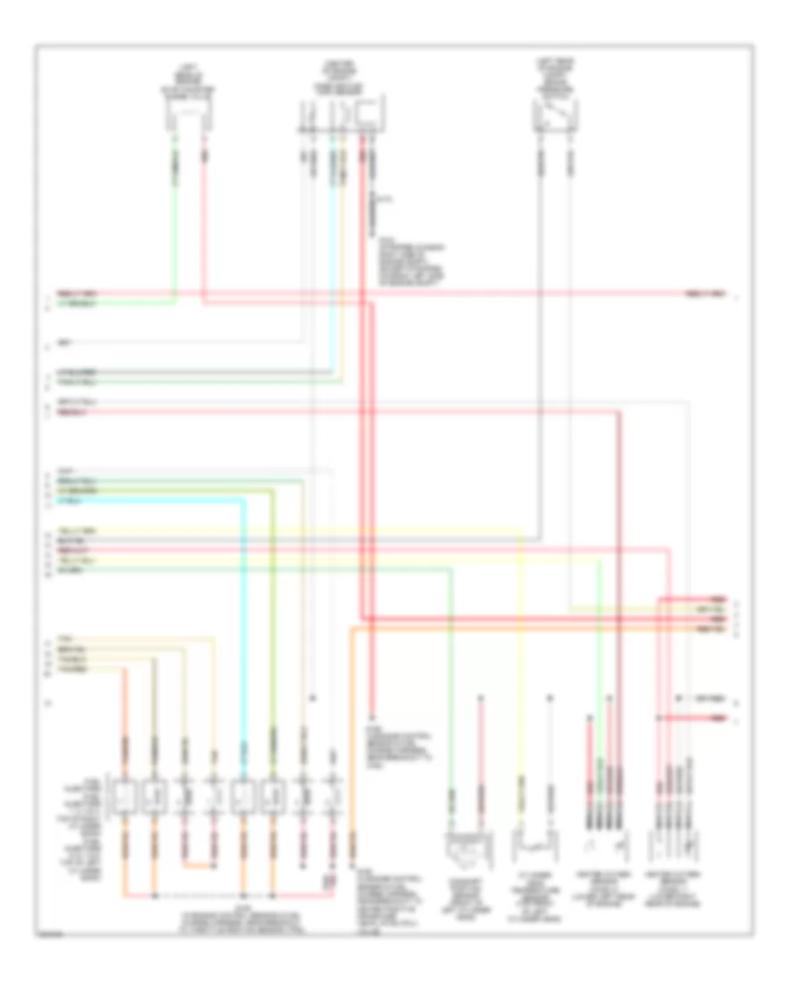
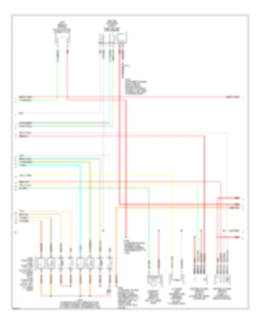
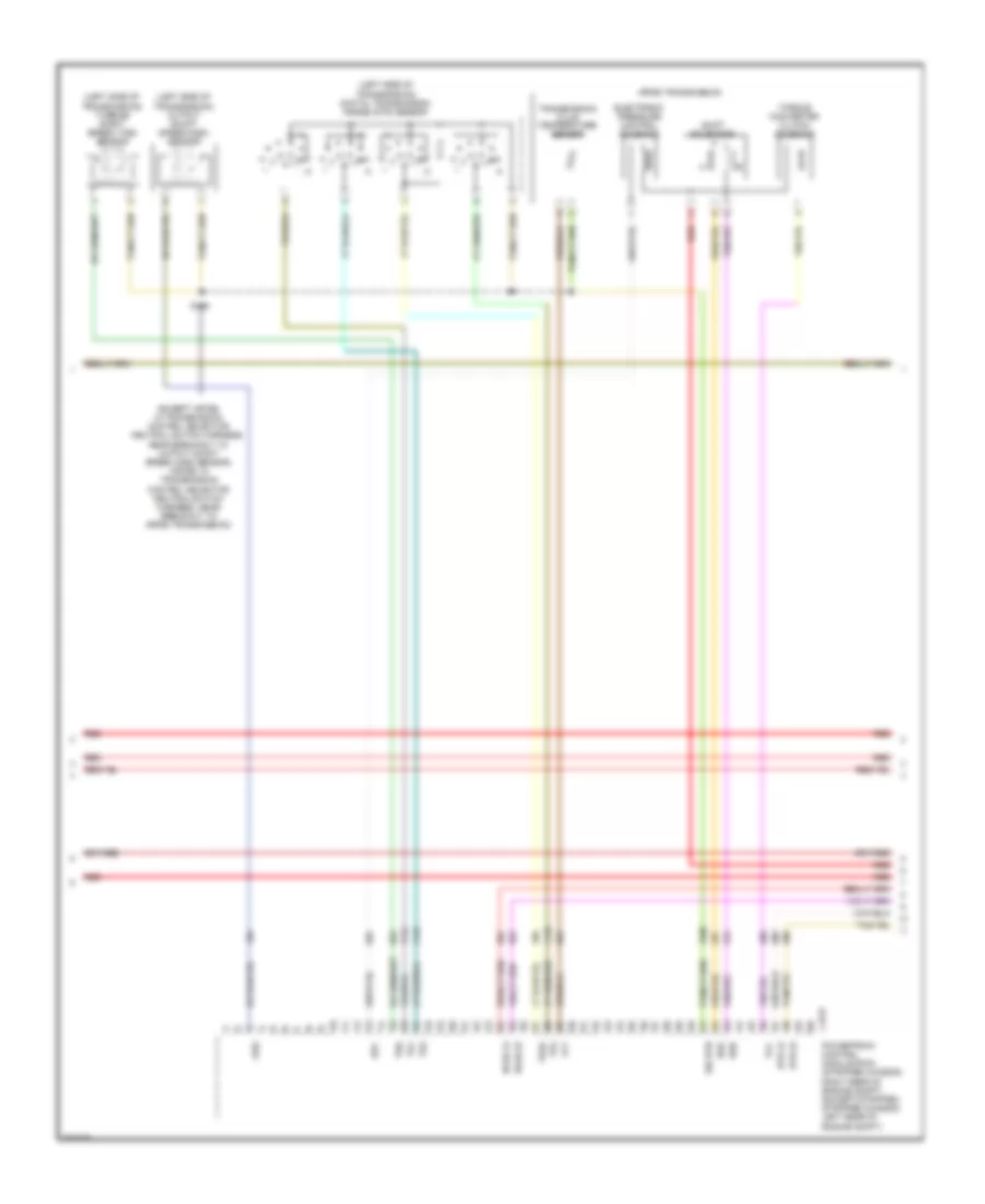
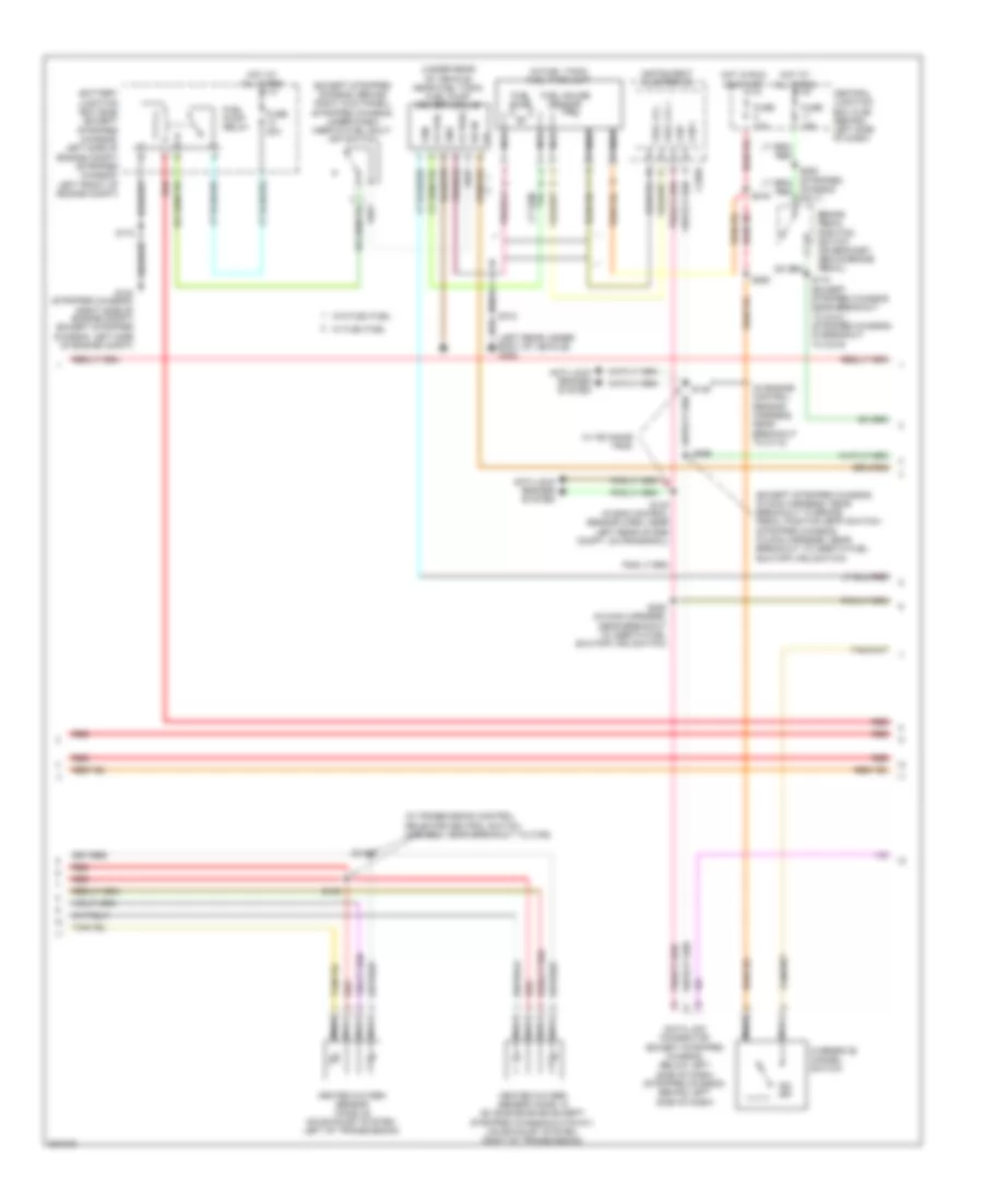
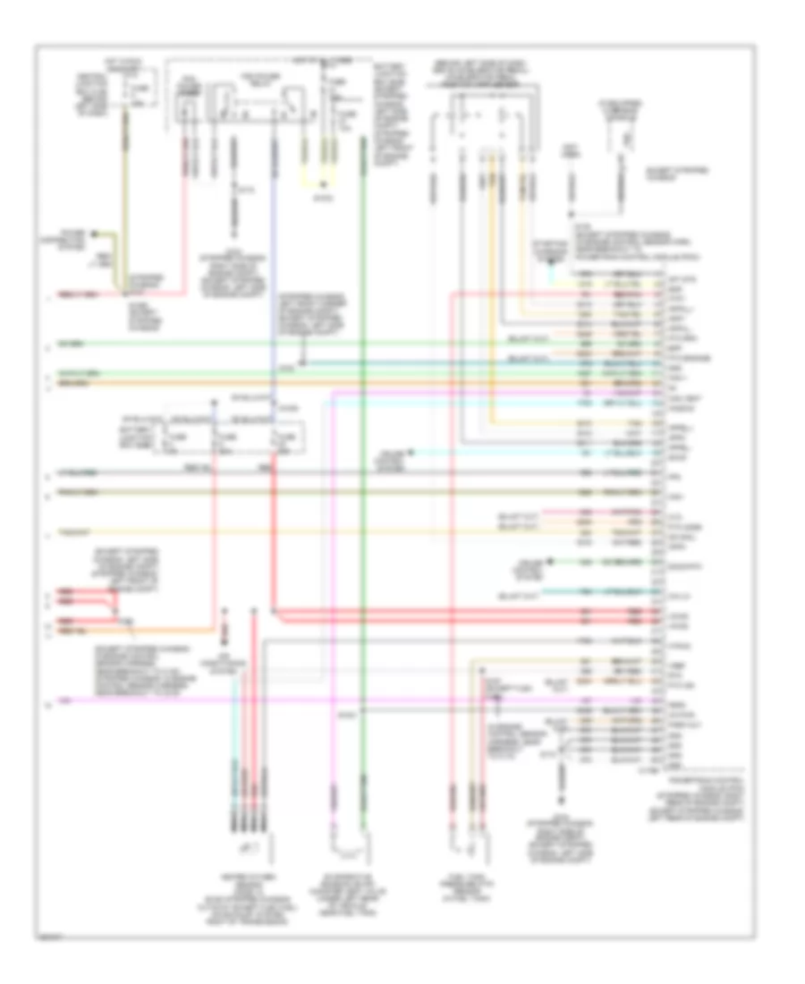
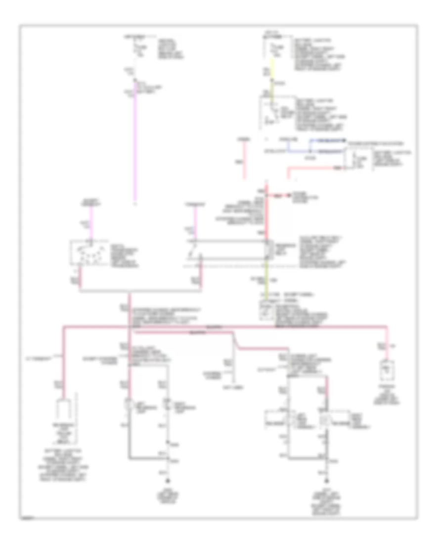
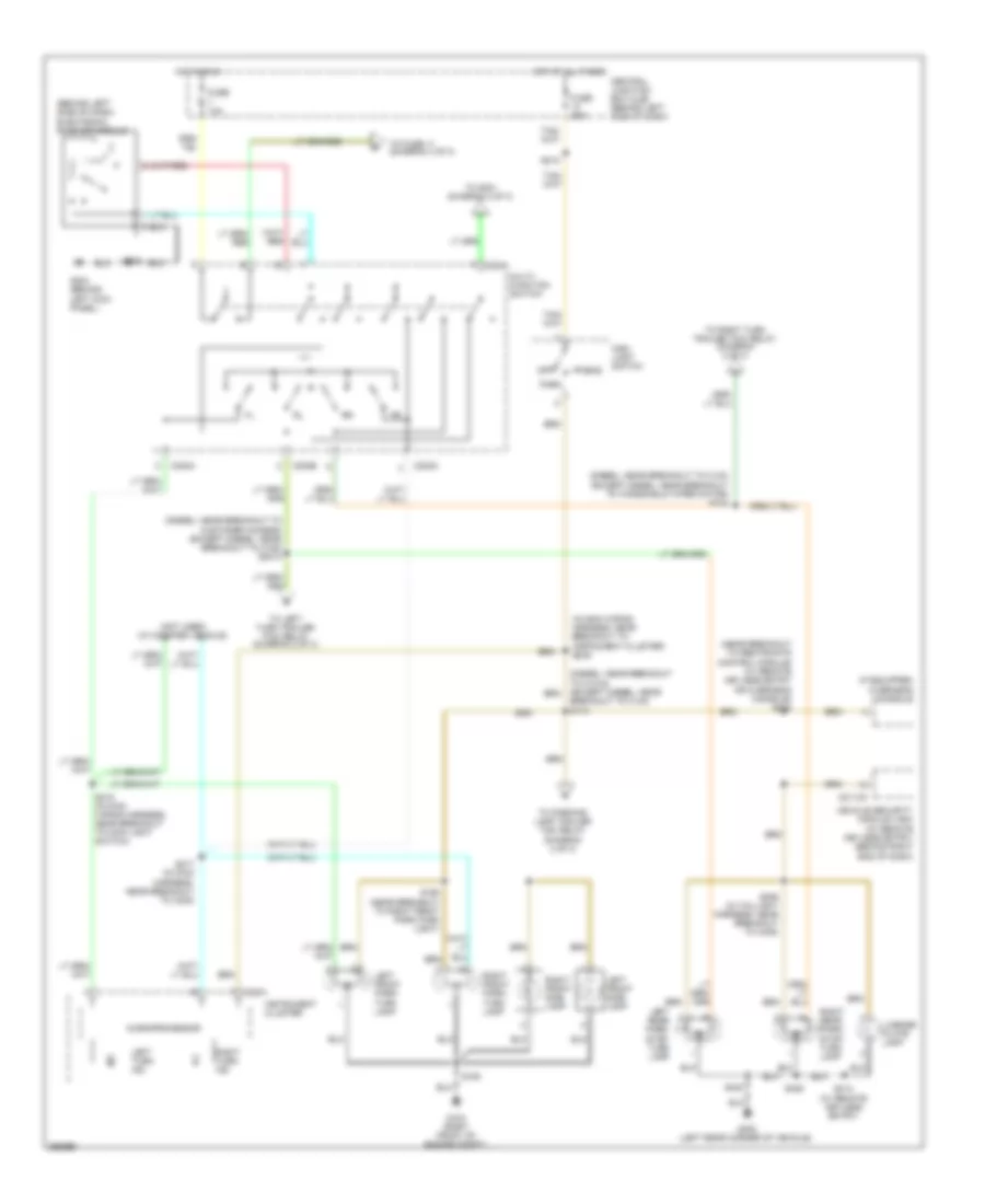
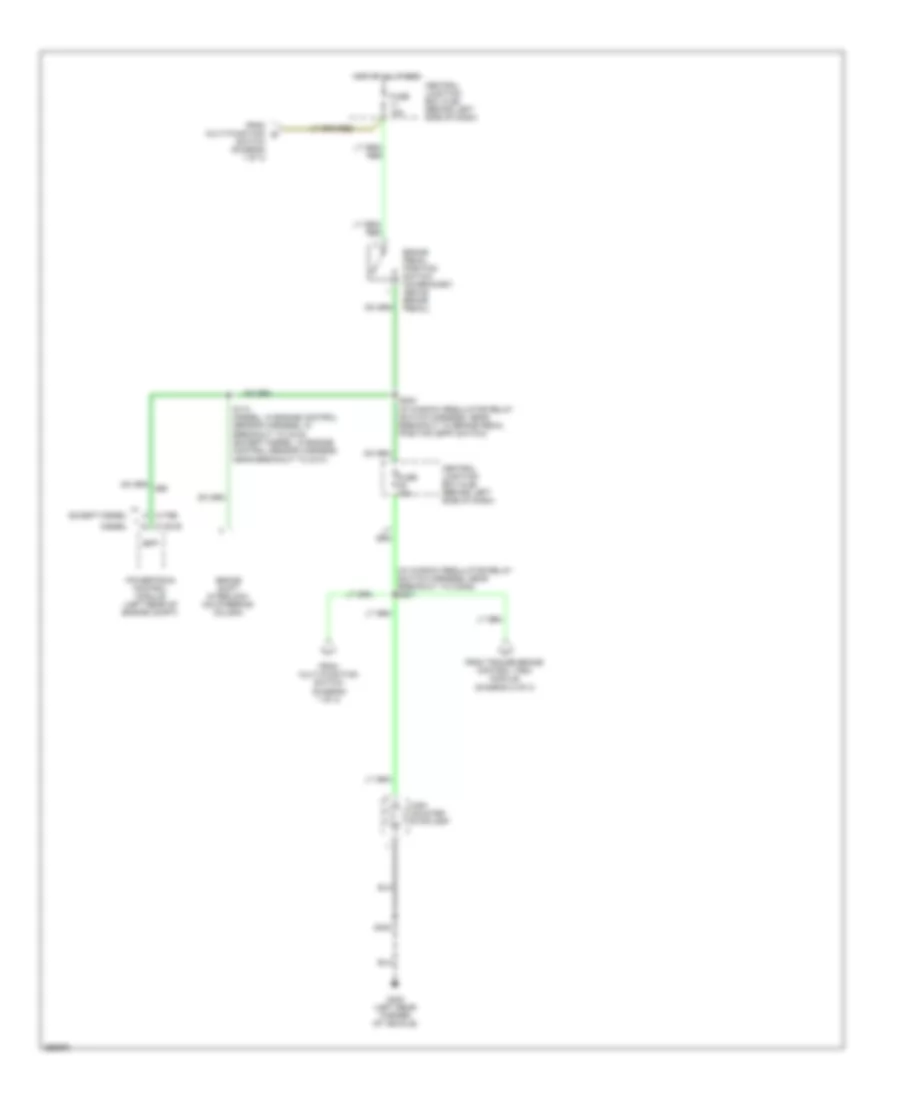
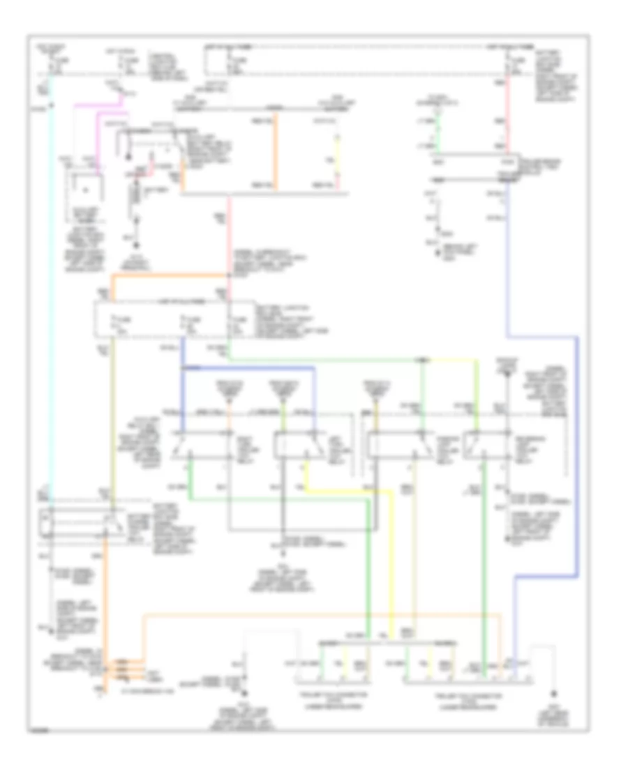
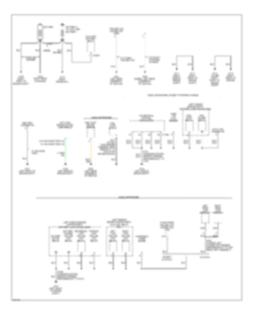
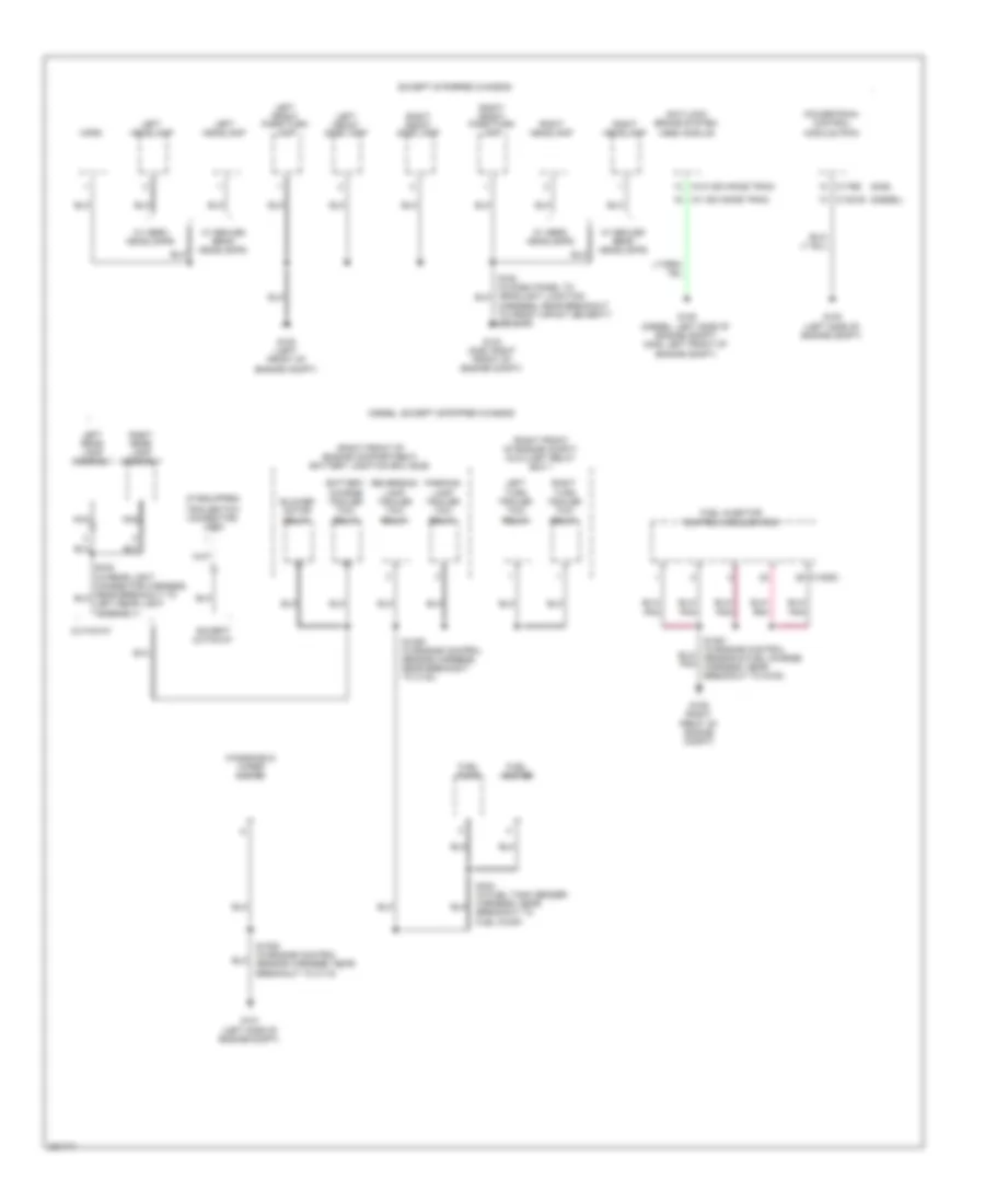
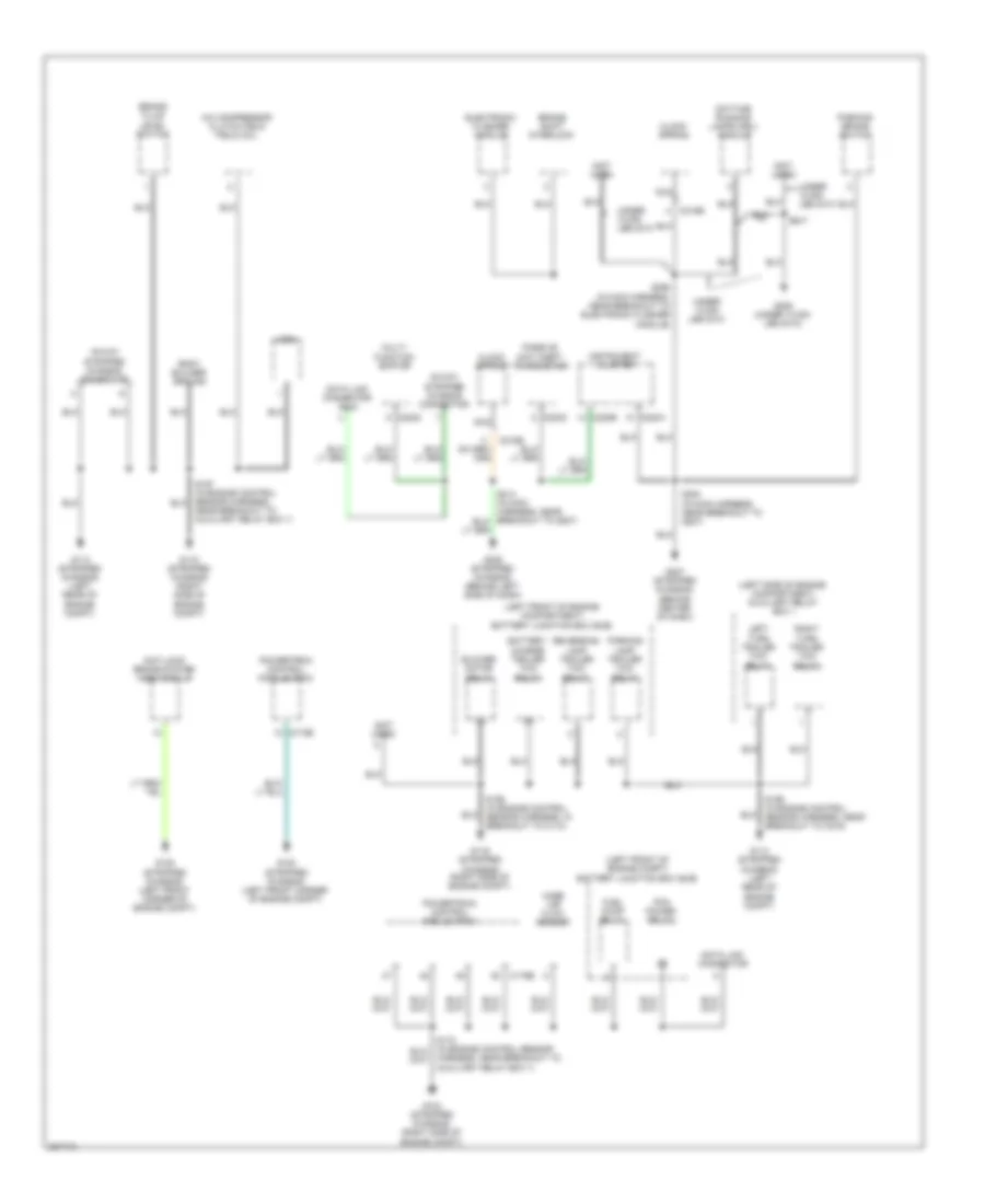
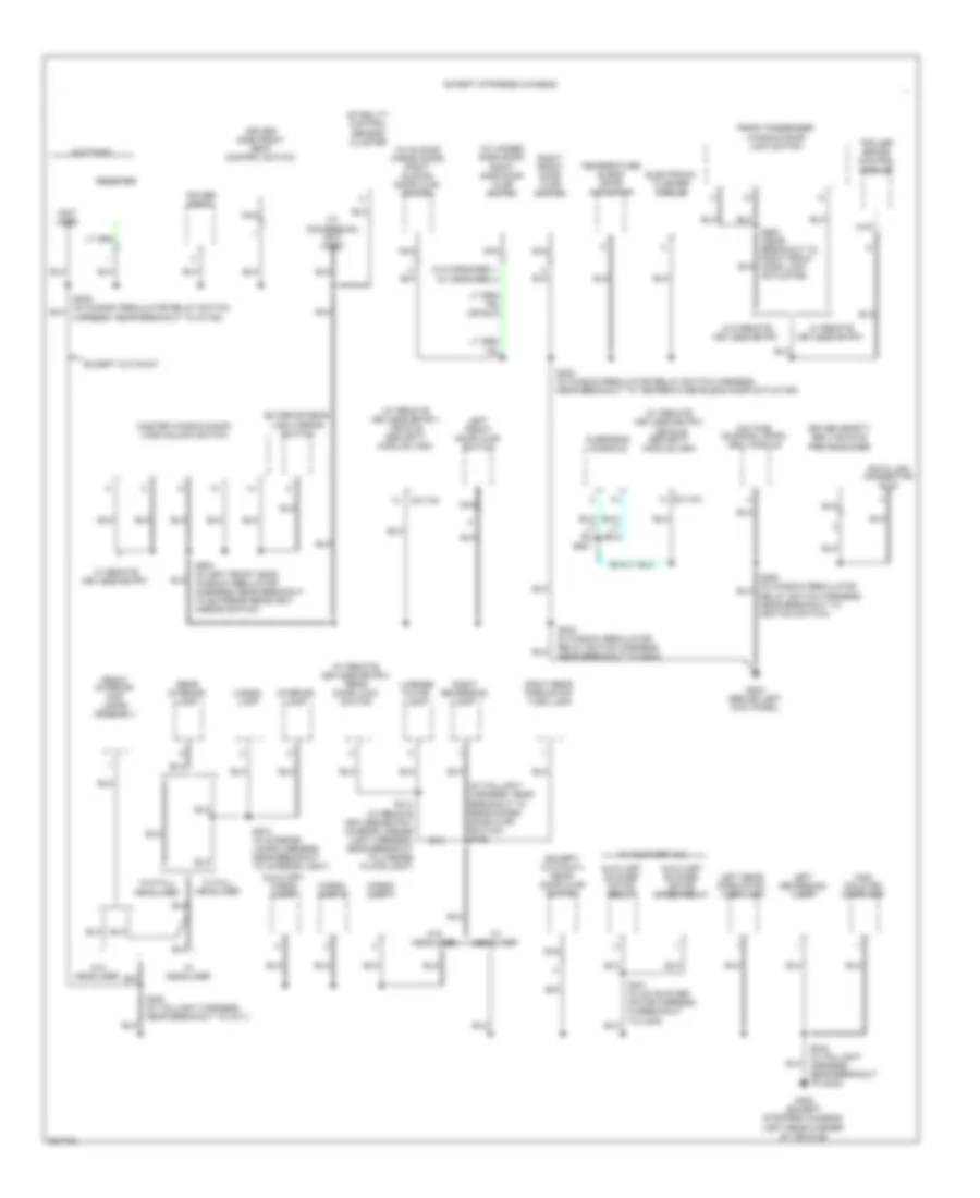
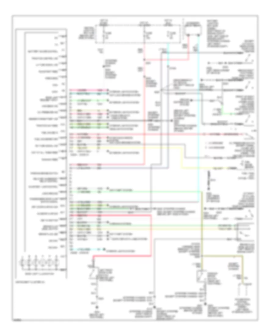
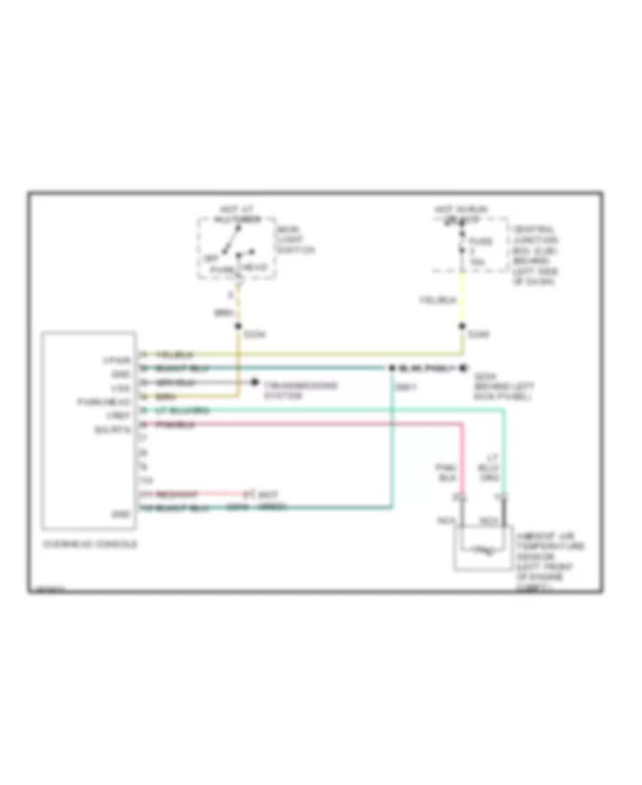
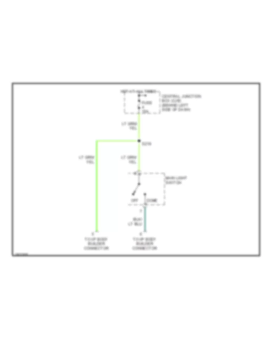
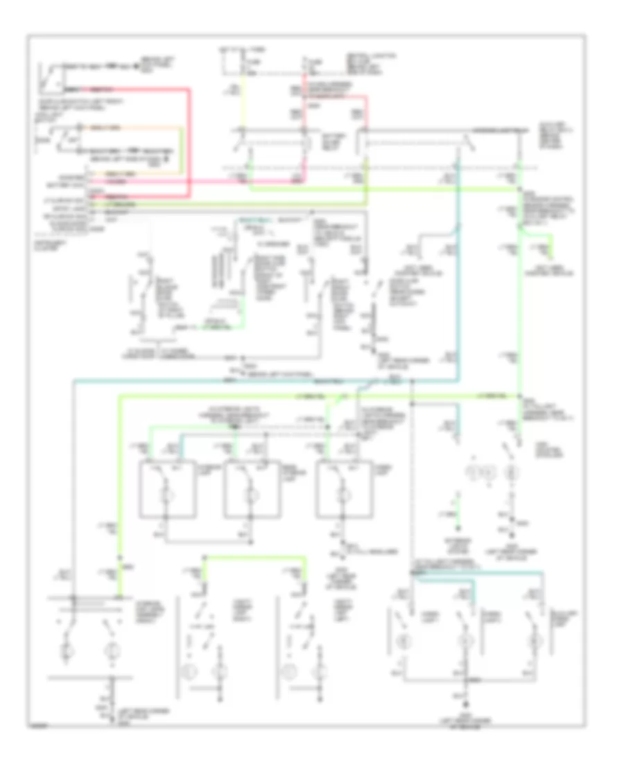
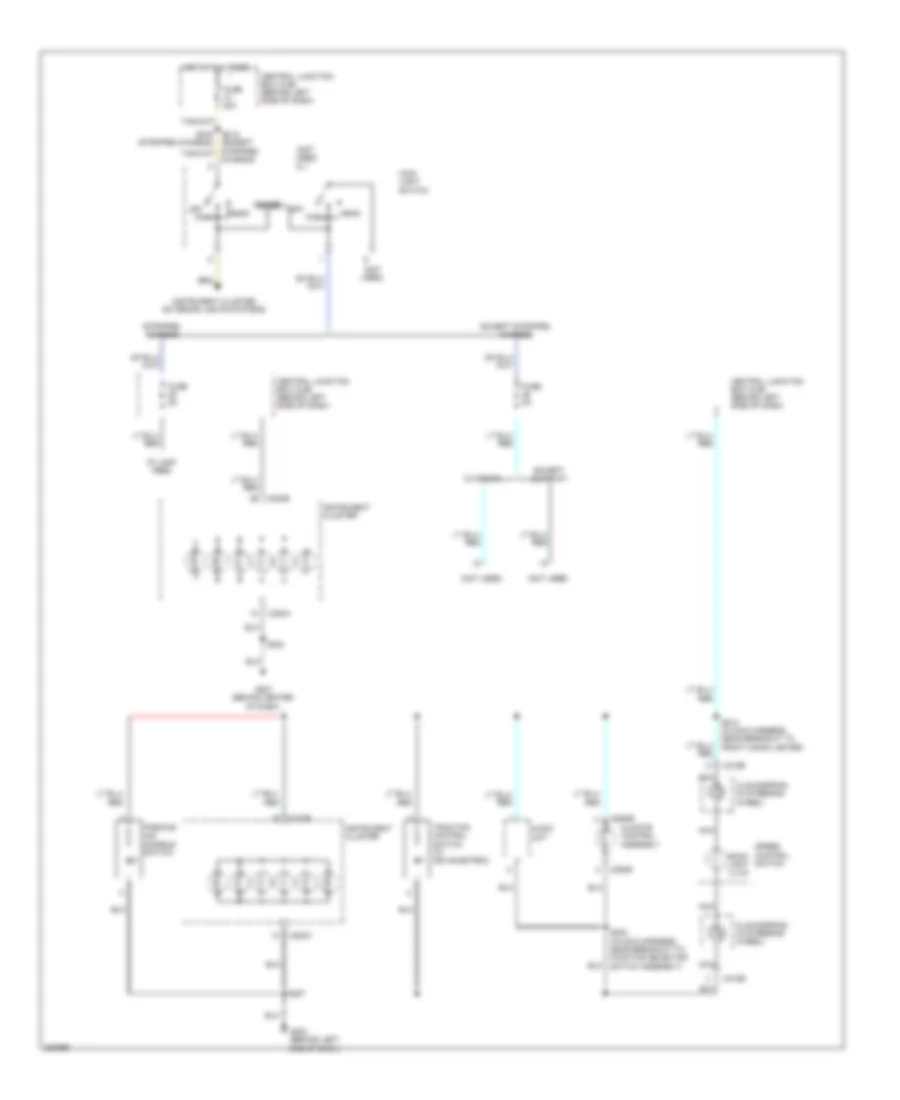
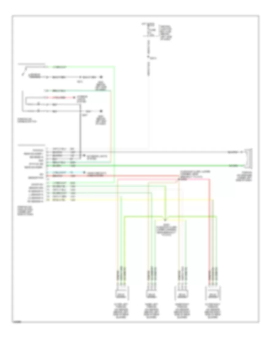
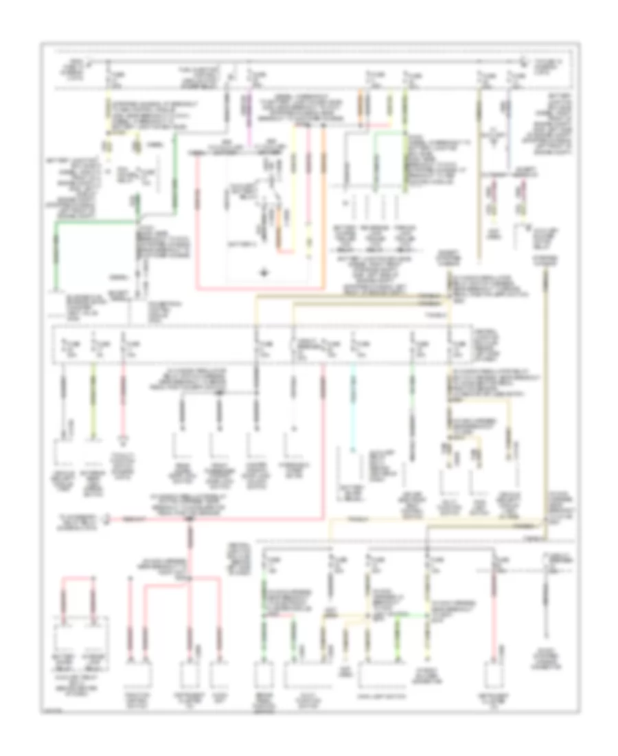
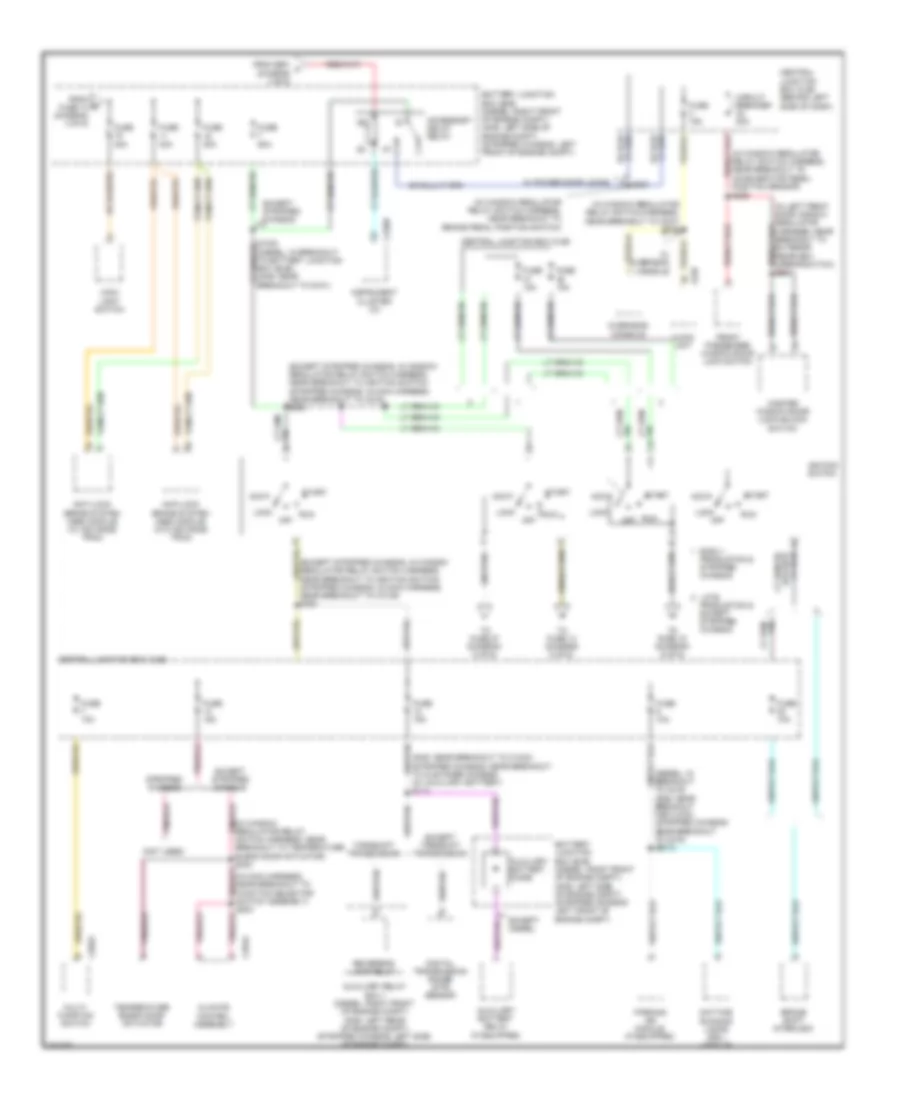
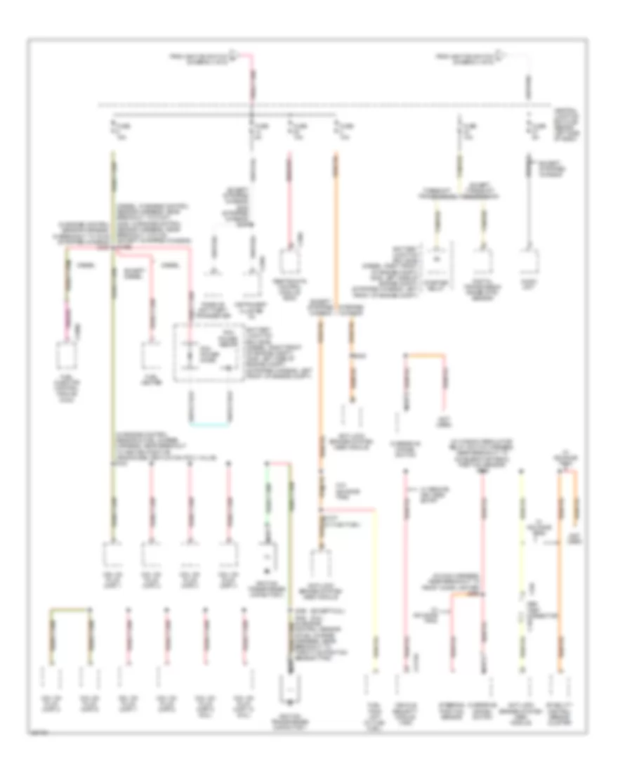
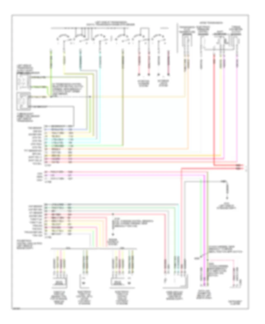
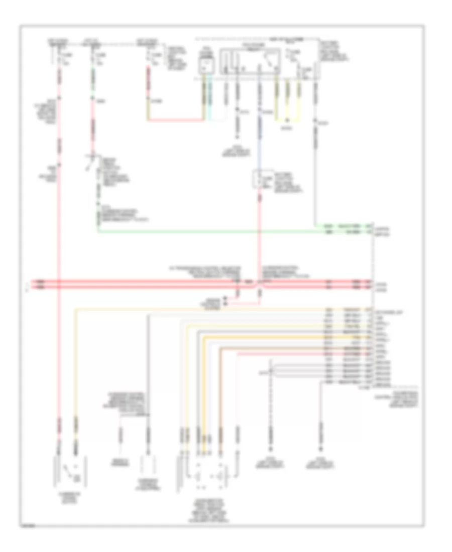
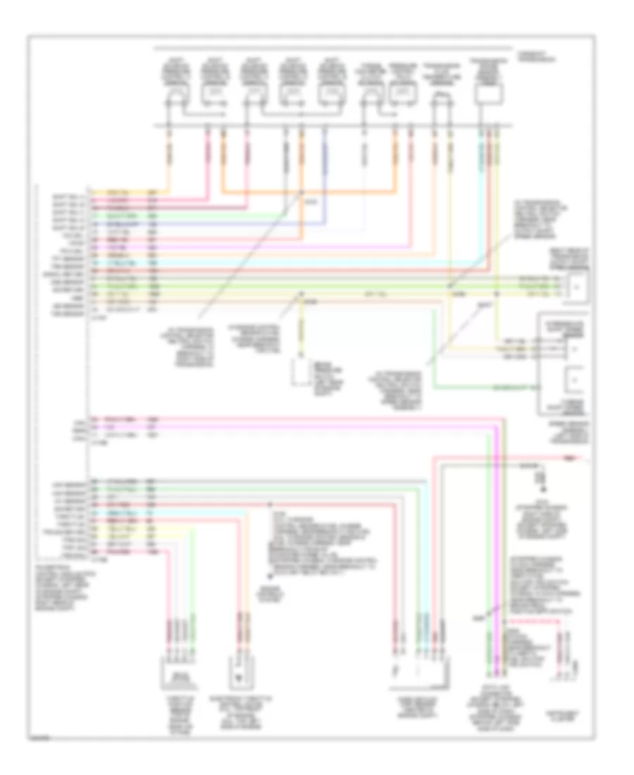
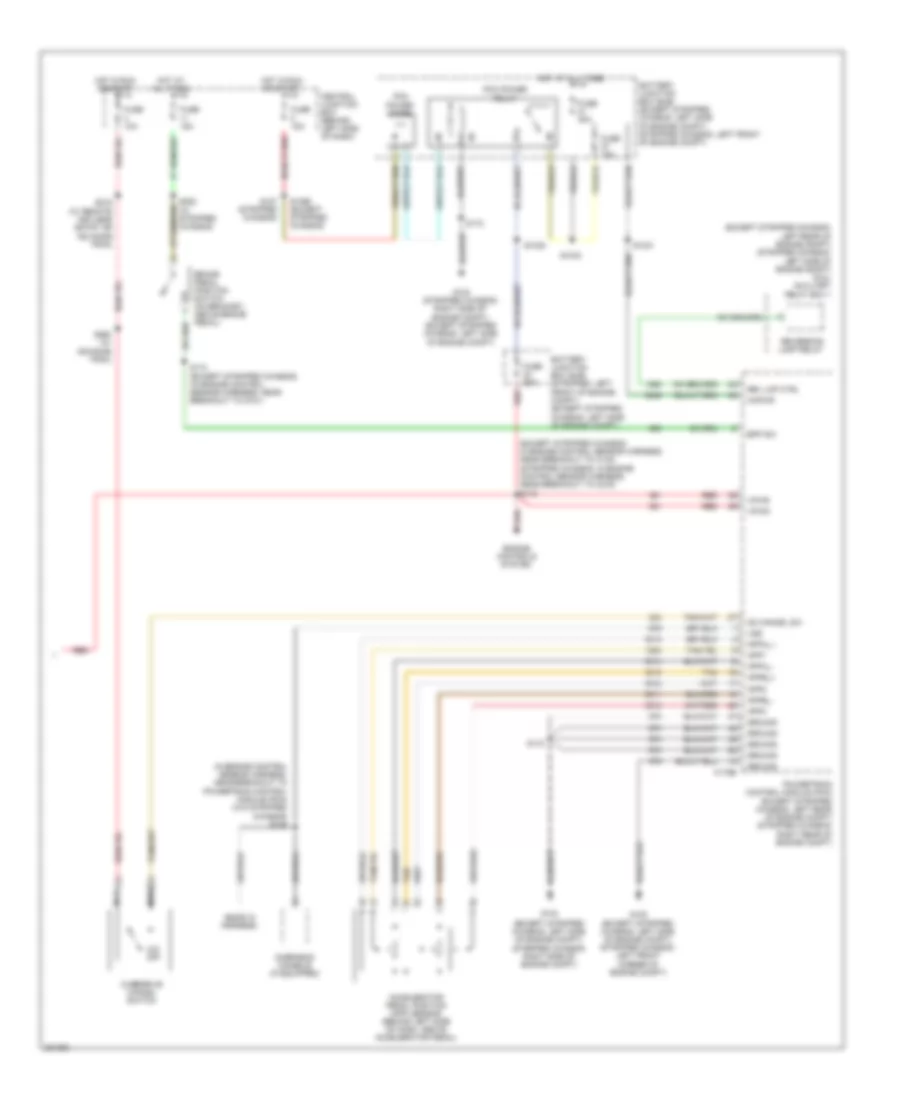
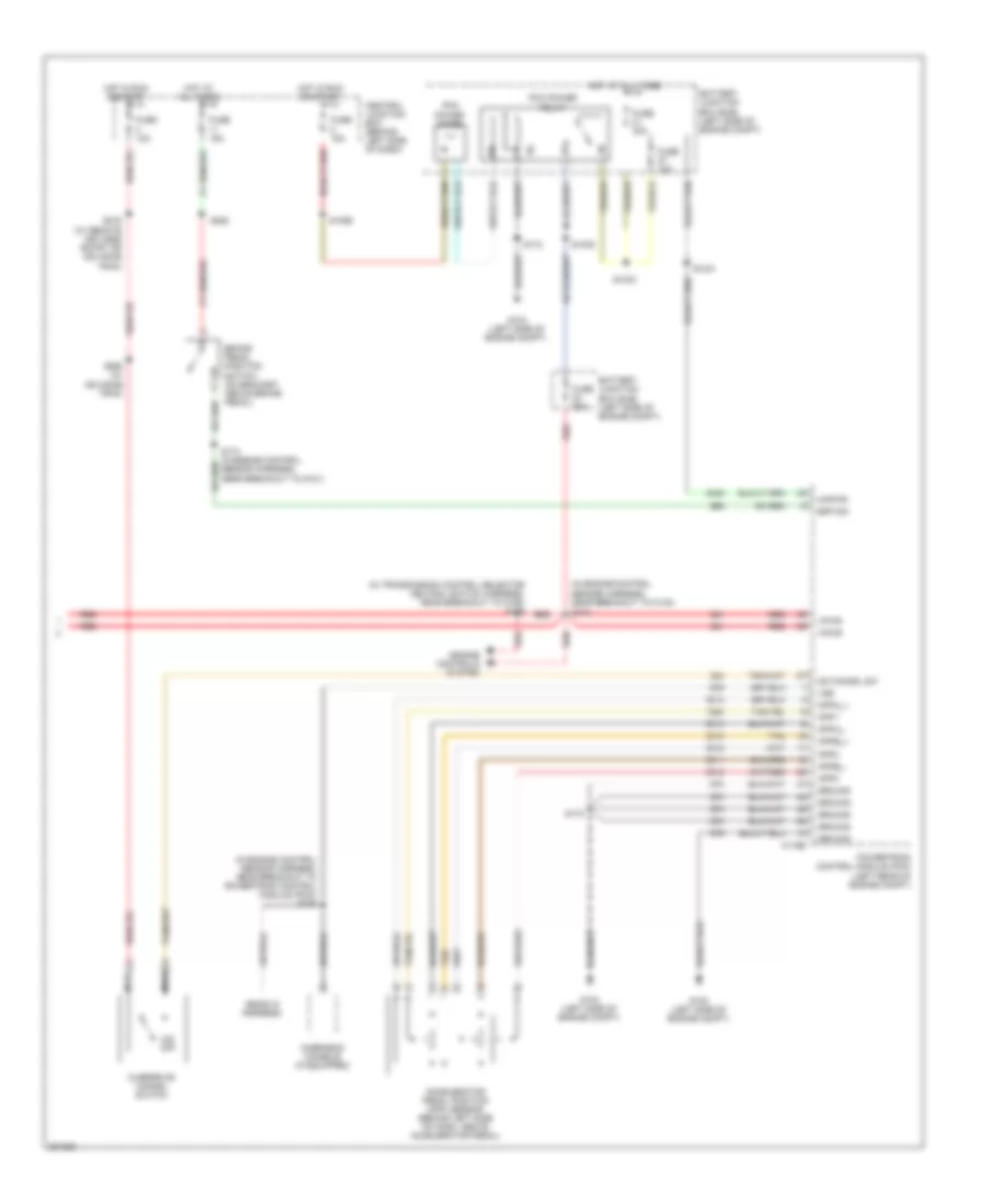
List of elements for Manual A/C Wiring Diagram (2 of 2) for Ford Econoline E150 2008:
63
(4.6l & 5.4l: top front of left cylinder head)
(diesel) s1029
(diesel: in engine control sensor harness, near breakout to c1047) (gas: in engine control sensor & fuel charge harness, near breakout for c192) s136
(in engine control sensor & fuel charge harness, near breakout to air charge temperature (act) sensor) s1059
(right front of engine compt) g107
A/c
A/c clutch field coil (lower right front of engine)
A/c clutch relay
A/c high pressure switch (right side of engine compt)
A/c sw
Acpsw
Auxiliary relay box 1 (diesel: right front of engine compt) (gas: left rear of engine compt)
Battery junction box (bjb) (diesel: right front of engine compt) (gas: left side of engine compt)
Blower motor relay
Blower motor resistor (right side of engine compt)
C1381b
C1381e
C175e
Cht
Clutch ctrl
Clutch switch
Controls
Cylinder head temperature sensor (6.8l: front of left cylinder head)
Diesel
Dual pressure switch (right front of engine compt)
Ect
Electronic fan clutch (diesel) (top front of engine)
Engine
Engine controls system
Engine coolant temperature (ect) sensor (diesel) (upper left front of engine)
Except diesel
Fan clutch
Front blower motor (right rear of engine compt)
Fss
Fuse 15a
Fuse 20a
Fuse 30a
Fuse 50a
G101 (diesel: left side of engine compt) (gas: left front of engine compt)
G107 (right front of engine compt)
Gas
Gnd
Hot at all times
Nca
Pcm
Power relay
Powertrain control module (pcm) (left rear of engine compt)
Red
Relay ctrl
S1005 (gas)
S101 (in engine control sensor harness, near breakout to powertrain control module)
S1033
S1057
S142
S143
S144 (diesel: in engine control sensor harness, near breakout to c144) (gas: in engine control sensor harness, near breakout to a/c clutch cycling pressure switch)
S186
Sig rtn
Sigrtn
Speed sensor
System
Thermal limiter
Vpwr
ANTI-LOCK BRAKES
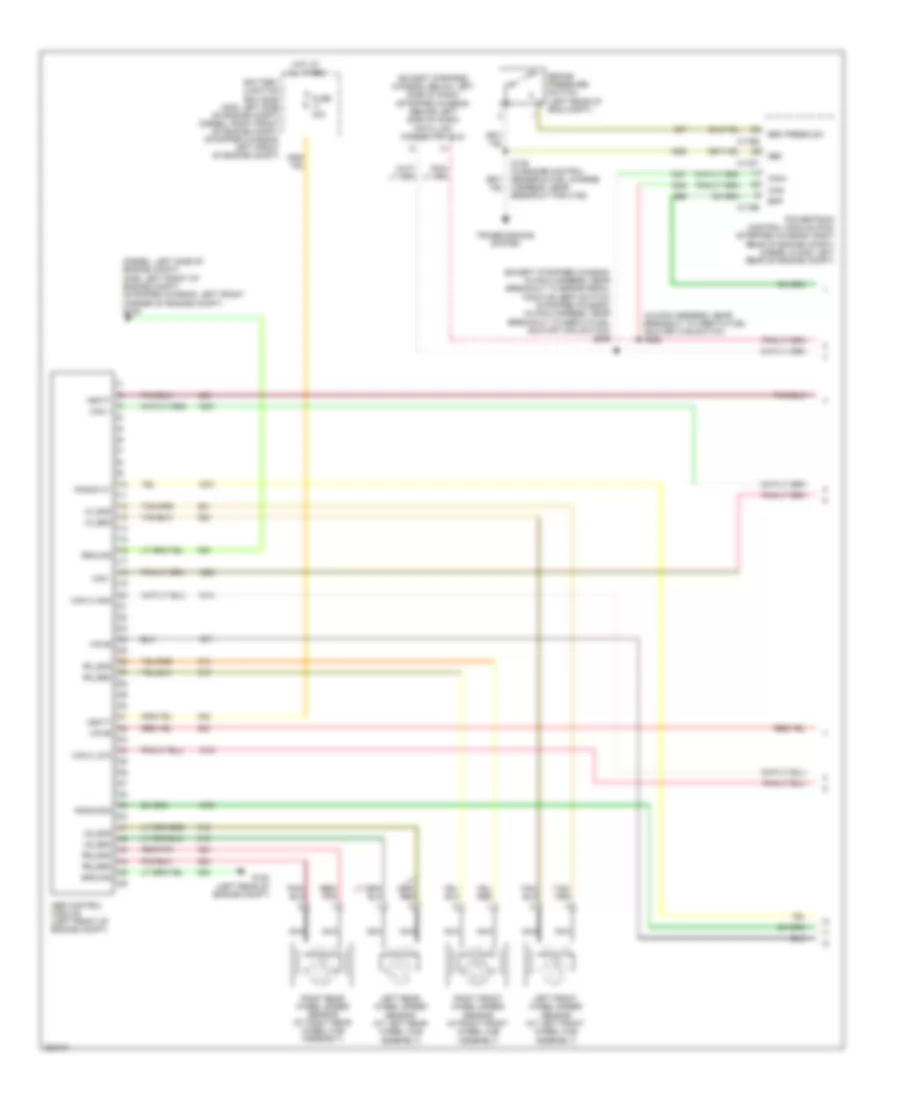
Anti-lock Brakes Wiring Diagram, with Stability Assist (1 of 2) for Ford Econoline E150 2008
List of elements for Anti-lock Brakes Wiring Diagram, with Stability Assist (1 of 2) for Ford Econoline E150 2008:
45
(diesel: left side of engine compt) (gas: left front of engine compt) (stripped chassis: left front corner of engine compt) g105
(except stripped chassis: below left side of dash) (stripped chassis: behind left side of dash) data link connector (dlc)
(except stripped chassis: in main harness, near breakout to brake pedal position (bpp) switch) (stripped chassis: in main harness, near breakout to inertia fuel shutoff (ifs) switch) s269
(in main harness, near breakout to inertia fuel shutoff (ifs) switch s228
Abs control module (left front of engine compt)
Angle a/1
Angle b/2
Battery junction box (bjb) (gas: left side of engine compt) (diesel: right front of engine compt) (stripped chassis: left front of engine compt)
Bpp
Brake pressure switch (left rear of eng compt)
Brk press sw
C175b
C175e
C175t
Can +
Can -
Can 2 high
Can 2 low
Can+
Can-
Fuse 40a
G122 (left rear of engine compt)
Ground
Hot at all times
Left front wheel speed sensor (at left front wheel hub assembly)
Left rear wheel speed sensor (at left rear wheel hub assembly)
Lf_gnd
Lf_sen
Lr_gnd
Lr_sen
Nca
Powertrain control module (pcm) (stripped chassis: right rear of engine compt) (diesel & gas: left rear of engine compt)
Red/ pnk
Red/pnk
Ref
Rf_gnd
Rf_sen
Right front wheel speed sensor (at right front wheel hub assembly)
Right rear wheel speed sensor (at right rear wheel hub assembly)
Rr_gnd
Rr_sen
S139 (in engine control sensor & fuel charge harness, near breakout for c192)
Transmissions system
Vbatt
Vpwr
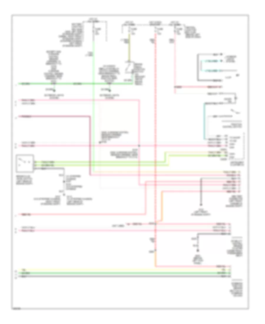
Anti-lock Brakes Wiring Diagram, with Stability Assist (2 of 2) for Ford Econoline E150 2008
List of elements for Anti-lock Brakes Wiring Diagram, without Stability Assist for Ford Econoline E150 2008:
49
(at left front wheel hub assembly) left front wheel speed sensor
(diesel & torqshift diesel: in transmission control selector neutral switch harness, in breakout to c1148) (gas & torqshift: in transmission control selector neutral switch harness, near breakout to output shaft speed (oss) sensor)
(diesel & torqshift diesel: in transmission control selector neutral switch harness, in breakout to c1148) (gas & torqshift: in transmission control selector neutral switch harness, near breakout to speed sensor assembly)
(in engine control sensor & fuel charge harness, near breakout for c192) (gasoline) s139
(left side of transmission) turbine shaft speed (tss) sensor
(right rear of transmission) outputshaft speed (oss) sensor
(stripped chassis: right rear of engine compt) (except stripped chassis: left rear of engine compt) powertrain control module (pcm)
4r75e transmission
Abs control module (left front of engine compt)
Battery junction box (bjb) (gas: left side of engine compt) (diesel: right front of engine compt) (stripped chassis: left front of engine compt)
C1381t
C175t
Can +
Can -
Central junction box (cjb) (behind left side of dash)
Computer data lines system
Cruise control system
Diesel
Except diesel
Fl gnd
Fr gnd
Fuse 10a
Fuse 40a
G105 (gas: left front of engine compt) (diesel: left side of engine compt) (stripped chassis: left front corner of engine compt)
G122 (left rear of engine compt)
Gnd
Hot at all times
Hot in run or start
Intermediate shaft speed sensor
Iss
Lf whl spd +
Nca
Oss
Output shaft speed (oss) sensor (left side of transmission)
Rf whl spd +
Right front wheel speed sensor (at right front wheel hub assembly)
S1037
S1077
S198
S198 (in transmission control selector neutral switch harness, near breakout to 4r75e transmission)
Sig rtn
Speed sensor assembly (left side of transmission)
Torqshift transmission
Transmissions system
Tss
Turbine shaft speed sensor
Vbatt
Vpwr
Vref
ANTI-THEFT
Forced Entry Wiring Diagram (1 of 2) for Ford Econoline E150 2008
List of elements for 4.6L, Engine Performance Wiring Diagram (1 of 5) for Ford Econoline E150 2008:
71
(in engine control sensor & fuel charge harness, near breakout to c192)
(in engine control sensor & fuel charge harness, near breakout to egr system module (esm))
(in engine control sensor & fuel charge harness, near breakout to heated positive crankcase ventilation (pcv) valve)
(stripped chassis: in engine control sensor harness, near breakout to auxiliary relay box 1) (except stripped chassis: in engine control sensor & fuel charge harness, near breakout for c192)
Accr
Accs
Air conditioning system
C175e
Cd1a
Cd2d
Cd3b
Cd4g
Cd5f
Cd6e
Cd7c
Cd8h
Cht
Ckp +
Ckp -
Cmp
Coil on plugs (cop) (coil on plugs 1,2,3, & 4: top of right cylinder bank) (coil on plugs 5,6,7 & 8: top of left cylinder bank)
Crankshaft position sensor (lower center front of engine)
Egr system module (esm) (top of left cylinder bank cover)
Electronic throttle control (etc) module (top front of engine)
Esm-dpfe
Esm-evr
Esm-map
Etc ref
Etc rtn
Frp
Frt
Fuel rail pressure/ temperature sensor (top of right cylinder head)
Ho2s-11
Ho2s-21
Iat
Ignition transformer capacitor 1 (left front of engine)
Ignition transformer capacitor 2 (right front of engine)
Inj 1
Inj 2
Inj 3
Inj 4
Inj 5
Inj 6
Inj 7
Inj 8
Knock sensor (top right rear of engine)
Ks1 +
Ks1 -
Maf
Mafrtn
Nca
Pcvhc
Powertrain control module (pcm) (stripped chassis: right rear of engine compt) (except stripped chassis: left rear of engine compt)
Red
Red/pnk
S103 (at top left front of engine, in engine harness)
S136
S156
S158
S161
Shield
Sig rtn
Solid state
Tacm +
Tacm -
Tan
Tan/red
Tp1-ns
Tp2-ns
Vmv-cc
Vref engine
4.6L, Engine Performance Wiring Diagram (2 of 5) for Ford Econoline E150 2008
List of elements for 4.6L, Engine Performance Wiring Diagram (3 of 5) for Ford Econoline E150 2008:
29
(except 4r75e: in transmission control selector neutral switch harness, near breakout to output shaft speed (oss) sensor) (4r75e: in transmission control selector neutral switch harness, near breakout to 4r75e transmission)
(left side of transmission) digital transmission range (dtr) sensor
(left side of transmission) output shaft speed (oss) sensor
(left side of transmission) turbine shaft speed (tss) sensor
4r75e transmission
C175t
Electronic pressure control solenoid
Epc
Ho2s-12
Ho2s-22
Htr-12
Htr-22
Oss
Powertrain control module (pcm) (stripped chassis: right rear of engine compt) (except stripped stripped chassis: left rear of engine compt)
Red
S198
Shift solenoids
Sig rtn
Ssa
Ssb
Tcc
Tft
Torque converter clutch solenoid
Tr1
Tr2
Tr3a
Tr4
Transmission fluid temperature sensor
Tss
4.6L, Engine Performance Wiring Diagram (4 of 5) for Ford Econoline E150 2008
List of elements for 4.6L, Engine Performance Wiring Diagram (4 of 5) for Ford Econoline E150 2008:
51
(except stripped chassis: behind right kick panel) (stripped chassis: under dash) inertia fuel shut- off (ifs) switch
(except stripped chassis: in main harness, near breakout to brake pedal position (bpp) switch) (stripped chassis: in main harness, near breakout to inertia fuel shutoff (ifs) switch)
(in engine control sensor harness, near breakout to c110)
(in fuel tank) fuel tank unit
(in transmission control selector neutral switch harness, near breakout to c192)
(left rear under- body of vehicle) g300
(under rear of vehicle, near fuel tank) fuel pump driver module
(w/ flex fuel) s1077
Anti-lock brakes system
Battery junction box (bjb) (except stripped chassis: left side of engine compt) (stripped chassis: left front of engine compt)
Brake pedal position switch (on bracket, above brake pedal)
Can +
Can -
Central junction box (cjb) (behind left side of dash)
Data link connector (except stripped chassis: below left side of dash) (stripped chassis: behind left side of dash)
Fp pwr
Fp rtn
Fpm
Fuel gauge sensor
Fuel lvl +
Fuel lvl -
Fuel pump
Fuel pump relay
Fuse 10a
Fuse 15a
Fuse 20a
G104 (stripped chassis: right side of engine compt) (except stripped chassis: left side of engine compt)
Gnd
Heated oxygen sensor (ho2s) 12 (on exhaust system, right of transmission)
Heated oxygen sensor (ho2s) 22 (on exhaust system, left of transmission)
Hot at all times
Hot in run or start
Ifs in
Instrument cluster (ic)
Nca
O/d off
Overdrive cancel switch
Red
S100
S102
S146
S148 (in engine control sensor harness, near breakout to c110)
S172
S174 (except stripped chassis: near breakout to g101) (stripped chassis: in breakout to c219)
S228 (in main harness, near breakout to inertia fuel shutoff (ifs) switch)
S260
S269
S312
W/ advance trac
W/ flex fuel
W/o flex fuel
4.6L, Engine Performance Wiring Diagram (5 of 5) for Ford Econoline E150 2008
List of elements for 4.6L, Engine Performance Wiring Diagram (5 of 5) for Ford Econoline E150 2008:
74
(behind left side of dash, above accelerator pedal) accelerator pedal position (app) sensor
(except stripped chassis: in engine control sensor harness, near breakout to c140) (stripped chassis: in engine control sensor harness, near breakout to c219)
(except stripped chassis: left side of engine compt) (stripped chassis: left front of engine compt)
(if equipped) overhead console
(in engine control sensor harness, near breakout to c110)
(not used)
(stripped chassis: left front of engine compt) (except stripped chassis: left side of engine compt)
4x4 lo
Aft std
Air conditioning system exterior lights system
App1
App2
App3
Appa_+
Appa_-
Appb_+
Appb_-
Battery junction box (bjb)
Battery junction box (bjb) (except stripped chassis: left side of engine compt) (stripped chassis: left front of engine compt)
Bpp
C110
C175b
Can +
Can -
Can vent
Central junction box (cjb) (behind left side of dash)
Cruise control system
Cto
Evaporative emission (evap) canister vent valve (under left rear of vehicle, near fuel tank)
Except stripped chassis
Feps
Fpm
Ftpt
Fuel tank pressure (ftp) sensor (in fuel tank)
Fuse 10a
Fuse 15a
Fuse 20a
Fuse 30a
Fuse 5a
G100
G104 (stripped chassis: right side of engine compt) (except stripped chassis: left side of engine compt)
Gnd
Hot at all times
Hot in run or start
Ka pwr
Od cncl
Park out
Pcm power diode
Pcm power relay
Power distribution system
Powertrain control module (pcm) (stripped chassis: right rear of engine compt) (except stripped chassis: left rear of engine compt)
Pto engage
Pto ind
Pto mode
Pto rpm
Red
Red/pnk
Rtn
S1021
S1033
S1035
S1065
S135 (except stripped chassis) (in engine control sensor harness, near breakout to powertrain control module (pcm)
S142
S157 (except flex fuel)
S172
Sccs
Sccs rtn
Smr
Starting/ charging system
Tan
Vpwr
Vref
Vss
5.4L
5.4L, Engine Performance Wiring Diagram, with Torqshift (1 of 5) for Ford Econoline E150 2008
List of elements for 5.4L, Engine Performance Wiring Diagram, with Torqshift (1 of 5) for Ford Econoline E150 2008:
65
(in engine control sensor & fuel charge harness, near breakout to heated positive crankcase ventilation (pcv) valve)
(in engine control sensor & fuel charge harness, near breakout to throttle position sensor (tps))
(stripped chassis: in engine control sensor harness, near breakout to auxiliary relay box 1) (except stripped chassis: in engine control sensor & fuel charge harness, near breakout for c192)
Accr
Accs
Air conditioning system
Bpp
C175e
Cd1a
Cd2d
Cd3b
Cd4g
Cd5f
Cd6e
Cd7c
Cd8h
Cht
Ckp +
Ckp -
Cmp
Coil on plugs (cop) (coil on plugs 1, 2, 3, & 4: top of right cylinder bank) (coil on plugs 5, 6, 7 & 8: top of left cylinder bank)
Crankshaft position sensor (lower center front of engine)
Electronic throttle control (etc) motor (top front of engine)
Etc ref
Etc rtn
Frp
Frt
Fuel rail pressure/ temperature sensor (top of right cylinder head)
Ho2s-11
Ho2s-21
Iat
Ignition transformer capacitor 1 (left front of engine)
Ignition transformer capacitor 2 (right front of engine)
Inj 1
Inj 2
Inj 3
Inj 4
Inj 5
Inj 6
Inj 7
Inj 8
Knock sensor (top rear of engine)
Ks1 +
Ks1 -
Maf
Mafrtn
Nca
Powertrain control module (pcm) (stripped chassis: right rear of engine compt) (except stripped chassis: left rear of engine compt)
Red/pnk
S103 (at top left front of engine, in engine harness)
S136
S156
S161
Shield
Sig rtn
Solid state
Tacm +
Tacm -
Tan
Tan/red
Throttle position sensor (tps) (top of engine, near air intake)
Tp1-ns
Tp2-ns
Vmv-cc
Vref engine
5.4L, Engine Performance Wiring Diagram, with Torqshift (2 of 5) for Ford Econoline E150 2008
List of elements for 5.4L, Engine Performance Wiring Diagram, with Torqshift (4 of 5) for Ford Econoline E150 2008:
52
(except stripped chassis: behind right kick panel) (stripped chassis: under dash) inertia fuel shut- off switch
(except stripped chassis: in main harness, near breakout to brake pedal position (bpp) switch) (stripped chassis: in main harness, near breakout to inertia fuel shutoff (ifs) switch)
(in engine control sensor harness, near breakout to c110)
(in fuel tank) fuel tank unit
(in transmission control selector neutral switch harness, near breakout to speed sensor assembly)
(left rear under- body of vehicle) g300
(under rear of vehicle, near fuel tank) fuel pump driver module
Anti-lock brakes system
Battery junction box (bjb) (except stripped chassis: left side of engine compt) (stripped chassis: left front of engine compt)
Brake pedal position switch (on bracket, above brake pedal)
Can +
Can -
Central junction box (cjb) (behind left side of dash)
Chassis only)
Data link connector (except stripped chassis: below left side of dash) (stripped chassis: behind left side of dash)
Fp pwr
Fp rtn
Fpm
Fuel gauge sensor
Fuel lvl +
Fuel lvl -
Fuel pump
Fuel pump relay
Fuse 10a
Fuse 15a
Fuse 20a
G104 (stripped chassis: right side of engine compt) (except stripped chassis: left side of engine compt)
Gnd
Heated oxygen sensor (ho2s) 12 (e-150/e-250/e-350 except stripped chassis/cutaway) (on exhaust system, right of transmission)
Heated oxygen sensor (ho2s) 22 (on exhaust system, left of transmission)
Hot at all times
Hot in run or start
Ifs in
Instrument cluster (ic)
Nca
O/d off
Overdrive cancel switch
Red
S100
S102
S146
S148 (in engine control sensor harness, near left rear of eng compt, on frame rail)
S172
S174 (except stripped chassis: near breakout to g101) (stripped chassis: in breakout to c219)
S216
S228 (in main harness, near breakout to inertia fuel shutoff (ifs) switch)
S260
S269
S312
W/ advance trac
W/ flex fuel
W/o flex fuel
5.4L, Engine Performance Wiring Diagram, with Torqshift (5 of 5) for Ford Econoline E150 2008
List of elements for 5.4L, Engine Performance Wiring Diagram, with Torqshift (5 of 5) for Ford Econoline E150 2008:
80
(behind left side of dash, above accelerator pedal) accelerator pedal position (app) sensor
(except stripped chassis: in engine control sensor harness, near breakout to c140) (stripped chassis: in engine control sensor harness, near breakout to c219)
(except stripped chassis: left side of engine compt) (stripped chassis: left front of engine compt)
(if equipped) overhead console
(in engine control sensor harness, near breakout to c110)
(not used)
(stripped chassis) s127
(stripped chassis: left front corner of engine compt) (except stripped chassis: left side of engine compt)
4x4 lo
Aft std
Air conditioning system
App1
App2
App3
Appa_+
Appa_-
Appb_+
Appb_-
Battery junction box (bjb)
Battery junction box (bjb) (except stripped chassis: left side of engine compt) (stripped chassis: left front of engine compt)
Bpp
C175b
Can +
Can -
Can vent
Central junction box (cjb) (behind left side of dash)
Cruise control system
Cto
Evaporative emission (evap) canister vent valve (under left rear of vehicle, near fuel tank)
Except stripped chassis
Exterior lights system
Feps
Fpm
Ftpt
Fuel tank pressure (ftp) sensor (in fuel tank)
Fuse 10a
Fuse 15a
Fuse 20a
Fuse 30a
Fuse 5a
G100
G104 (stripped chassis: right side of engine compt) (except stripped chassis: left side of engine compt)
Gnd
Heated oxygen sensor (ho2s) 12 (e-350 stripped chassis/ cutaway except flex fuel) (on exhaust system, right of transmission)
Ho2s-23
Hot at all times
Hot in run or start
Htr-23
Ka pwr
Nca
Od cncl
P/n
Park out
Pcm power diode
Pcm power relay
Power distribution system
Powertrain control module (pcm) (stripped chassis: right rear of engine compt) (except stripped chassis: left rear of engine compt)
Pto engage
Pto ind
Pto mode
Pto rpm
Red
Red/pnk
Rtn
Rvrs lp rly
S1021 (in engine control sensor harn, stripped chassis: neat breakout to g101) except stripped chassis: near breakout to customer access)
S1033
S1035
S1065 (except stripped chassis)
S135 (except stripped chassis) (in engine control sensor harness, near breakout to powertrain control module (pcm))
S142
S157 (except flex fuel)
S172
Sccs
Sccs rtn
Smr
Starting/ charging system
Tan
Vpwr
Vref
5.4L, Engine Performance Wiring Diagram, without Torqshift (1 of 5) for Ford Econoline E150 2008
List of elements for 5.4L, Engine Performance Wiring Diagram, without Torqshift (1 of 5) for Ford Econoline E150 2008:
64
(in engine control sensor & fuel charge harness, near breakout to heated positive crankcase ventilation (pcv) valve)
(in engine control sensor & fuel charge harness, near breakout to throttle position sensor (tps))
(stripped chassis: in engine control sensor harness, near breakout to auxiliary relay box 1) (except stripped chassis: in engine control sensor & fuel charge harness, near breakout for c192)
Accr
Accs
Air conditioning system
C175e
Cd1a
Cd2d
Cd3b
Cd4g
Cd5f
Cd6e
Cd7c
Cd8h
Cht
Ckp +
Ckp -
Cmp
Coil on plugs (cop) (coil on plugs 1, 2, 3, & 4: top of right cylinder bank) (coil on plugs 5, 6, 7 & 8: top of left cylinder bank)
Crankshaft position sensor (lower center front of engine)
Electronic throttle control (etc) motor (top front of engine)
Etc ref
Etc rtn
Frp
Frt
Fuel rail pressure/ temperature sensor (top of right cylinder head)
Ho2s-11
Ho2s-21
Iat
Ignition transformer capacitor 1 (left front of engine)
Ignition transformer capacitor 2 (right front of engine)
Inj 1
Inj 2
Inj 3
Inj 4
Inj 5
Inj 6
Inj 7
Inj 8
Knock sensor (top rear of engine)
Ks1 +
Ks1 -
Maf
Mafrtn
Nca
Powertrain control module (pcm) (stripped chassis: right rear of engine compt) (except stripped chassis: left rear of engine compt)
Red/pnk
S103 (at top left front of engine, in engine harness)
S136
S156
S161
Shield
Sig rtn
Solid state
Tacm +
Tacm -
Tan
Tan/red
Throttle position sensor (tps) (top of engine, near air intake)
Tp1-ns
Tp2-ns
Vmv-cc
Vref engine
5.4L, Engine Performance Wiring Diagram, without Torqshift (2 of 5) for Ford Econoline E150 2008
List of elements for 5.4L, Engine Performance Wiring Diagram, without Torqshift (3 of 5) for Ford Econoline E150 2008:
29
(except 4r75e: in transmission control selector neutral switch harness, near breakout to output shaft speed (oss) sensor) (4r75e: in transmission control selector neutral switch harness, near breakout to 4r75e transmission)
(left side of transmission) digital transmission range (dtr) sensor
(left side of transmission) output shaft speed (oss) sensor
(left side of transmission) turbine shaft speed (tss) sensor
4r75e transmission
C175t
Electronic pressure control solenoid
Epc
Ho2s-12
Ho2s-22
Htr-12
Htr-22
Oss
Powertrain control module (pcm) (stripped chassis: right rear of engine compt) (except stripped stripped chassis: left rear of engine compt)
Red
S198
Shift solenoids
Sig rtn
Ssa
Ssb
Tcc
Tft
Torque converter clutch solenoid
Tr1
Tr2
Tr3a
Tr4
Transmission fluid temperature sensor
Tss
5.4L, Engine Performance Wiring Diagram, without Torqshift (4 of 5) for Ford Econoline E150 2008
List of elements for 5.4L, Engine Performance Wiring Diagram, without Torqshift (4 of 5) for Ford Econoline E150 2008:
52
(except stripped chassis: behind right kick panel) (stripped chassis: under dash) inertia fuel shut- off switch
(except stripped chassis: in main harness, near breakout to brake pedal position (bpp) switch) (stripped chassis: in main harness, near breakout to inertia fuel shutoff (ifs) switch)
(in engine control sensor harness, near breakout to c110)
(in fuel tank) fuel tank unit
(in transmission control selector neutral switch harness, near breakout to c192)
(left rear under- body of vehicle) g300
(under rear of vehicle, near fuel tank) fuel pump driver module
Anti-lock brakes system
Battery junction box (bjb) (except stripped chassis: left side of engine compt) (stripped chassis: left front of engine compt)
Brake pedal position switch (on bracket, above brake pedal)
Can +
Can -
Central junction box (cjb) (behind left side of dash)
Data link connector (except stripped chassis: below left side of dash) (stripped chassis: behind left side of dash)
Fp pwr
Fp rtn
Fpm
Fuel gauge sensor
Fuel lvl +
Fuel lvl -
Fuel pump
Fuel pump relay
Fuse 10a
Fuse 15a
Fuse 20a
G104 (stripped chassis: right side of engine compt) (except stripped chassis: left side of engine compt)
Gnd
Heated oxygen sensor (ho2s) 12 (e-150/e-250/e-350 except stripped chassis/cutaway) (on exhaust system, right of transmission)
Heated oxygen sensor (ho2s) 22 (on exhaust system, left of transmission)
Hot at all times
Hot in run or start
Ifs in
Instrument cluster (ic)
Nca
O/d off
Only)
Overdrive cancel switch
Red
S100
S102
S146
S148 (in eng control sensor harn, near left rear of eng compt, on frame rail)
S172
S174 (except stripped chassis: near breakout to g101) (stripped chassis: in breakout to c219)
S216
S228 (in main harness, near breakout to inertia fuel shutoff (ifs) switch)
S260
S269
S312
W/ advance trac
W/ flex fuel
W/o flex fuel
5.4L, Engine Performance Wiring Diagram, without Torqshift (5 of 5) for Ford Econoline E150 2008
List of elements for 5.4L, Engine Performance Wiring Diagram, without Torqshift (5 of 5) for Ford Econoline E150 2008:
78
(behind left side of dash, above accelerator pedal) accelerator pedal position (app) sensor
(except stripped chassis: in engine control sensor harness, near breakout to c140) (stripped chassis: in engine control sensor harness, near breakout to c219)
(except stripped chassis: left side of engine compt) (stripped chassis: left front of engine compt)
(if equipped) overhead console
(in engine control sensor harness, near breakout to c110)
(not used)
(stripped chassis) s127
(stripped chassis: left front corner of engine compt) (except stripped chassis: left side of engine compt)
4x4 lo
Aft std
Air conditioning system
App1
App2
App3
Appa_+
Appa_-
Appb_+
Appb_-
Battery junction box (bjb)
Battery junction box (bjb) (except stripped chassis: left side of engine compt) (stripped chassis: left front of engine compt)
Bpp
C175b
Can +
Can -
Can vent
Central junction box (cjb) (behind left side of dash)
Cruise control system
Cto
Evaporative emission (evap) canister vent valve (under left rear of vehicle, near fuel tank)
Except stripped chassis
Feps
Fpm
Ftpt
Fuel tank pressure (ftp) sensor (in fuel tank)
Fuse 10a
Fuse 15a
Fuse 20a
Fuse 30a
Fuse 5a
G100
G104 (stripped chassis: right side of engine compt) (except stripped chassis: left side of engine compt)
Gnd
Heated oxygen sensor (ho2s) 12 (e-350 stripped chassis/ cutaway except flex fuel) (on exhaust system, right of transmission)
Ho2s-23
Hot at all times
Hot in run or start
Htr-23
Ka pwr
Nca
Od cncl
Park out
Pcm power diode
Pcm power relay
Power distribution system
Powertrain control module (pcm) (stripped chassis: right rear of engine compt) (except stripped chassis: left rear of engine compt)
Pto engage
Pto ind
Pto mode
Pto rpm
Red
Red/pnk
Rtn
S1021
S1033
S1035
S1065 (except stripped chassis)
S135 (except stripped chassis) (in engine control sensor harn, near breakout to powertrain control module (pcm))
S142
S157 (except flex fuel)
S172
Sccs
Sccs rtn
Smr
Starting/ charging system
Tan
Vpwr
Vref
Vss
EXTERIOR LIGHTS
Backup Lamps Wiring Diagram for Ford Econoline E150 2008
List of elements for Backup Lamps Wiring Diagram for Ford Econoline E150 2008:
49
(diesel)
(except diesel)
(in taillight harness, near breakout to high mounted stoplight) s403
(not used)
(stripped chassis: near breakout to customer access) (diesel: near breakout to c1019) (gas: near breakout to c237) s130
Auxiliary relay box 1 (diesel: right front of engine compt) (except diesel: left rear of engine compt) (stripped chassis: left side of engine compt)
Battery junction box (bjb) (diesel: right front of engine compt) (except diesel: left side of engine compt) (stripped chassis: left front of engine compt)
Battery junction box (bjb) (left side of engine compt)
C1381t
C175b
Central junction box (cjb) (behind left side of dash)
Cutaway
Diesel
Digital transmission range (dtr) sensor (left side of transmission)
Except stripped chassis
Except torqshift
Fuse 15a
Fuse 20a
Fuse 30a
G101 (diesel: left side of engine compt) (except diesel: left front of engine compt)
G400 (left rear corner of vehicle)
Gasoline
Hot at all times
Hot in run
Left rear lamp assembly
Left reversing lamp
Nca
Parking aid module (under left side of dash)
Pcm power relay
Pnk
Power distribution system
Powertrain control module (except stripped chassis: left rear of engine compt stripped chassis: right rear of engine compt)
Red
Rev in
Reverse
Reversing lamp relay
Reversing lamp trailer tow relay
Right rear lamp assembly
Right reversing lamp
Rvrs lp rly
S1033
S1035
S142 (diesel: near breakout to c1019) (gas: near breakout to c140) (stripped chassis: near breakout to c219)
S402
S406
S432
Stripped chassis
Torqshift
W/ torqshift
Exterior Lamps Wiring Diagram (1 of 3) for Ford Econoline E150 2008
(right front of engine compt) battery junction box (bjb)
Audio unit
Blower motor resistor
Brake fluid level switch
Brake shift interlock
C1381b
C202c
C218b
C220a
C220b
C294b
C294c
C294e
Climate control assembly
Clock spring
Data link connector
Diesel
Front cigar lighter
G107 (except stripped chassis) (right front of engine compt)
G200 (except stripped chassis) (behind right side of dash)
G202 (except stripped chassis) (behind left side of dash)
G203 (except stripped chassis) (behind left end of dash)
Instrument cluster
Instrument cluster (ic)
Instrument panel power point
Main light switch
Mass air flow sensor
Multi- function switch
Nca
Parking aid disable switch
Parking aid module (pam)
Parking brake switch
Passive anti-theft transceiver
Pcm power relay
Powertrain control module
S143 (diesel: in engine control sensor harness, near breakout to c144) (gas: in engine control sensor harness, near breakout to a/c clutch cycling pressure switch)
S172 (in engine control sensor harness, near breakout to windshield wiper motor)
S202 (in main harness, near breakout to function selector switch assembly)
S204 (in main harness, near breakout to passenger air bag module)
S207 (in main harness, near breakout to instrument cluster)
S214 (in main harness, near breakout to main light switch)
Traction control switch
Windshield washer pump motor
Windshield wiper motor
HEADLIGHTS
Headlights Wiring Diagram, with Stripped Chassis for Ford Econoline E150 2008
List of elements for Power Distribution Wiring Diagram (2 of 6) for Ford Econoline E150 2008:
45
(behind left kick panel) g204
(gas: in engine control sensor harness, in breakout to c219) (diesel: in engine control sensor harness, near breakout to c140) s2012
(gas: in engine control sensor harness, near breakout to g101) (stripped chassis: in engine control sensor harness, at breakout to abs control module) (diesel: in engine control sensor harness, in breakout to battery junction box (bjb)) s1034
(in engine control sensor harness, near breakout to auxiliary relay box 1) s1019
(in window regulator relay switch harness, near breakout to c237) s266
(not used)
(stripped chassis: in engine control sensor harness, near breakout to abs control module) (gas: in engine control sensor harness, near breakout to g101) (diesel: in engine control sensor harness, near breakout to c133) s1028
(stripped chassis: in engine control sensor harness, near breakout to powertrain control module (pcm)) (gas: in engine control sensor harness, in breakout to auxiliary relay box 1) (except diesel) s186
A/c clutch relay
Auxiliary relay box 1 (diesel: right front of engine compt) (gas: left rear of engine compt) (stripped chassis: left side of engine compt)
Battery junction box (bjb) (diesel: right front of engine compt) (gas: left side of engine compt) (stripped chassis: left front of engine compt)
C1251a
C219
Central junction box (cjb) (behind left side of dash)
Conversion van
Data link connector
Daytime running lamps (drl) module
Except cutaway
Except stripped chassis
From a fuse 13 (diagram 1 of 6)
Front cigar lighter
Fuse 10a
Fuse 10a (diesel)
Fuse 15a
Fuse 20a
Fuse 30a
Fuse 50a
Fuse 60a
G203 (behind left end of dash)
Horn relay
I/p body builder connector
Instrument panel power point
Left turn trailer tow relay
Power point
Red
Right turn trailer tow relay
S145 (diesel) (in engine control sensor harness, near breakout to g106)
S207
S235
S254
Secondary generator (w/ dual generators)
Starter relay
Stripped chassis
To fuse 21 (diagram 3 of 6)
Trailer brake control (tbc) module
Power Distribution Wiring Diagram (3 of 6) for Ford Econoline E150 2008
List of elements for Power Distribution Wiring Diagram (4 of 6) for Ford Econoline E150 2008:
67
(diesel: in breakout to c219) (gas: near breakout for c1033) (stripped chassis: near breakout to c219) s2013
(except stripped chassis: in window regulator relay switch harness, near breakout to ignition switch) (stripped chassis: in main harness, near breakout to c219) s230
(except stripped chassis: in window regulator relay switch harness, near breakout to ignition switch) (stripped chassis: in main harness, near breakout to c3139) s280
(gas: near breakout to c1033) (stripped chassis: near breakout to customer access) (w/ auxiliary battery) s113
(in left front door window regulator harness, near breakout to exterior rearview mirror switch) s501
(in main harness, near breakout to function selector switch assembly) s203
(in window regulator relay switch harness, near breakout to accelerator pedal position sensor)
(in window regulator relay switch harness, near breakout to brake pedal position switch)
(in window regulator relay switch harness, near breakout to c237) s245
(in window regulator relay switch harness, near breakout to temperature blend door actuator) s242
(not used)
Acc
Accessory delay relay
Anti-lock brake system (abs) module (w/ advance trac)
Anti-lock brake system (abs) module (w/o advance trac)
Audio unit
Auxiliary battery diode
Auxiliary battery relay (if equipped)
Auxiliary relay box 1 (diesel: right front of engine compt) (gas: left rear of engine compt) (stripped chassis: left side of engine compt)
Battery junction box (bjb) (diesel: right front of engine compt) (gas: left side of engine compt) (stripped chassis: left front of engine compt)
Brake shift interlock
C202a
C220b
C240
C294a
Central junction box (cjb)
Central junction box (cjb) (behind left side of dash)
Circuit breaker 20a
Climate control assembly
Daytime running lamps (drl) module
Digital transmission range (dtr) sensor
Early production & stripped chassis
Except diesel
Except stripped chassis
Except torqshift transmission
From e fuse 14 (diagram 3 of 6)
From s291 f (diagram 3 of 6)
Front passenger window/door lock switch
Fuse 10a
Fuse 15a
Fuse 30a
Fuse 40a
Fuse 60a
Ignition switch
Instrument cluster (ic)
Late
Lock
Main light switch
Master window/door lock/unlock switch
Multi- function switch
Off
Overhead console
Parking aid module (if equipped)
Production & except stripped chassis
Reversing lamp relay
Run
S227
S236
Start
Stripped chassis
Temperature blend door actuator
To fuse 14 (diagram 5 of 6)
To fuse 15 (diagram 6 of 6)
To fuse 27 (diagram 5 of 6)
Torqshift transmission
W/ overhead console
W/ power door locks
Power Distribution Wiring Diagram (5 of 6) for Ford Econoline E150 2008
List of elements for Power Distribution Wiring Diagram (5 of 6) for Ford Econoline E150 2008:
72
(6.8l)
(diesel: in engine control sensor harness, near breakout to c1047) (gas: in engine control sensor harness, near breakout to c140) (except stripped chassis) s1065
(except 6.8l)
(in engine control sensor & fuel charge harness, near breakout to heated positive crankcase ventilation (pcv) valve) s161
(in engine control sensor harness, in breakout to c219) (stripped chassis) s127
(in main harness, near breakout to front cigar lighter) s260
(in window regulator relay switch harness, near breakout to accelerator pedal position sensor) s216
(not used)
Anti-lock
Anti-lock brakes system (abs) module
Audio unit
Battery junction box (bjb) (diesel: right front of engine compt) (gas: left side of engine compt) (stripped chassis: left front of engine compt)
Brakes system (abs) module
C126 abs
C1388c
C2113a
C220a
C310a
Cancel switch
Central junction box (cjb) (behind left side of dash)
Coil on plug (cop) 1
Coil on plug (cop) 10 (6.8l)
Coil on plug (cop) 2
Coil on plug (cop) 3
Coil on plug (cop) 4
Coil on plug (cop) 5
Coil on plug (cop) 6
Coil on plug (cop) 7
Coil on plug (cop) 8
Coil on plug (cop) 9 (6.8l)
Control sensor cluster
Diesel
Digital transmission range (dtr) sensor
Except diesel
Except stripped chassis
Except torqshift transmission
From ignition switch k (diagram 4 of 6)
From ignition switch l (diagram 4 of 6)
Fuel
Fuel heater
Fuel injector control module (ficm)
Fuse 10a
Fuse 15a
Fuse 5a
Ignition transformer capacitor 1
Ignition transformer capacitor 2
Instrument cluster (ic)
Nca
Overdrive
Overdrive cancel switch
Passive anti-theft transceiver
Pcm power diode
Pcm power relay
Position sensor
Restraints control module (rcm)
S1077 (w/ flex fuel)
S156
S162 (in engine control sensor & fuel charge harness, near breakout to throttle position sensor (tps))
S248
Security module (vsm)
Stability
Starter relay
Steering
Stripped chassis
Tan/red
Tank unit (w/ flex fuel)
Test connector c126
Torqshift transmission
Vehicle
W/ advance trac
W/ remote keyless entry
W/o advance trac
Power Distribution Wiring Diagram (6 of 6) for Ford Econoline E150 2008
List of elements for Power Distribution Wiring Diagram (6 of 6) for Ford Econoline E150 2008:
23
(gas: in engine control sensor harness, near breakout to g101) (diesel: in engine control sensor harness, near breakout to c1019) (except stripped chassis) s1022
(in window regulator relay switch harness, near breakout to c237) (w/ remote keyless entry) s246
(not used)
16-way stripped chassis connector
Battery charge trailer tow relay
Battery junction box (bjb) (diesel: right front of engine compt) (gas: left side of engine compt) (stripped chassis: left front of engine compt)
Brake pedal position switch
C2113a
C220b
Central junction box (cjb) (behind left side of dash)
Except stripped chassis
From fuse 11 (diagram 3 of 6)
From ignition switch (diagram 4 of 6)
Fuse 15a
Fuse 5a
Instrument cluster (ic)
Multi- function switch
S256 (stripped chassis)
S282 (in main harness, near breakout to electronic flasher module)
Stripped chassis
Vehicle security module (vsm)
W/ remote keyless entry
Windshield wiper motor
POWER DOOR LOCKS
Power Door Locks Wiring Diagram, with Cutaway Chassis without Keyless Entry for Ford Econoline E150 2008
List of elements for Supplemental Restraints Wiring Diagram for Ford Econoline E150 2008:
31
C218a
C256
C310a
C310b
Can +
Can -
Central junction box (cjb) (behind left side of dash)
Clockspring (in steering wheel)
Computer data lines system
Dr ab fd 1
Dr ab rtn 1
Driver air bag unit (in steering wheel)
Driver's safety belt buckle pretensioner (under driver's seat)
Feed
Front impact severity sensor (front center of engine compt)
Fuse 10a
G204 (behind left kick panel)
Hot in run or start
Nca
Passenger air bag module (behind right side of dash)
Passenger's safety belt buckle pretensioner (under passenger's seat)
Ps ab fd 1
Ps ab rtn 1
Restraints control module (under driver's seat)
Return
Run/start
S250
Safety belt
Shorting bar
Shorting bar is engaged when harness connector is disconnected from module (shorting bars are connected between the following pins: 1-2, 3-4 & 15-16 of conn c310a)
Vref sig rtn
TRANSMISSION
4.6L
4.6L, Transmission Wiring Diagram (1 of 2) for Ford Econoline E150 2008
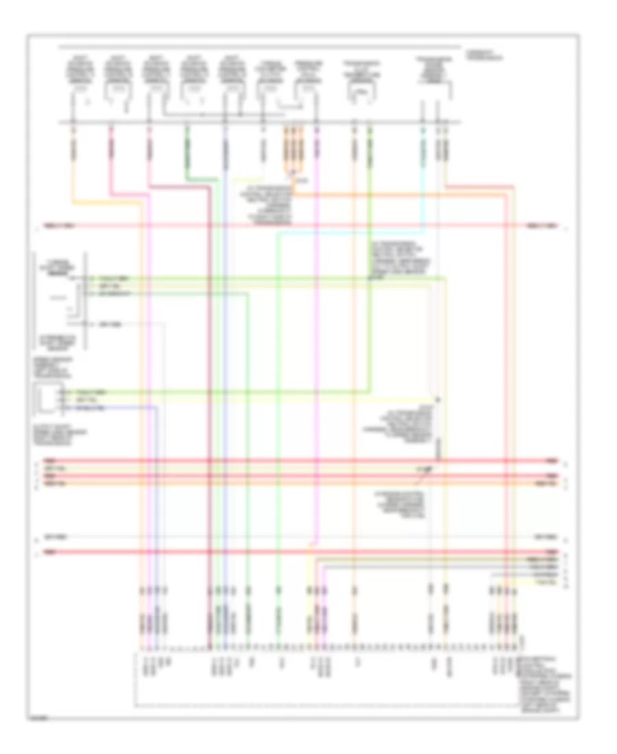
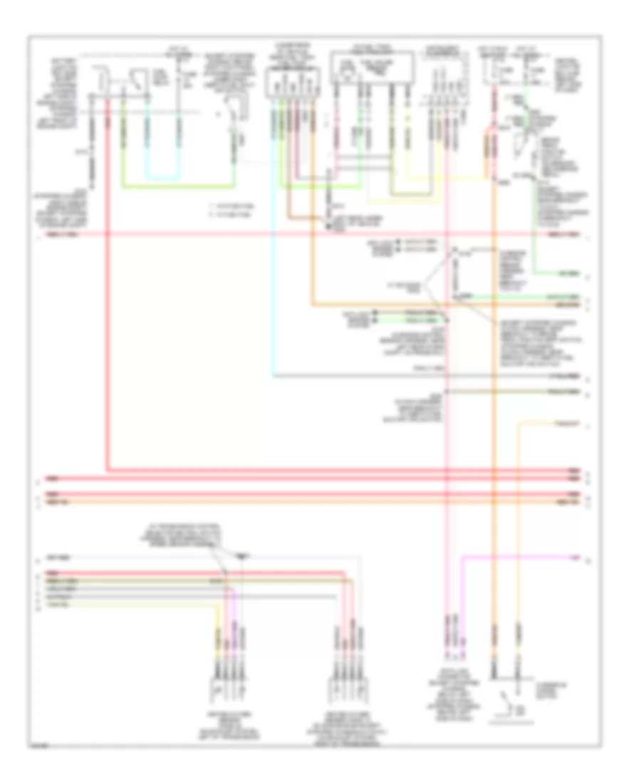
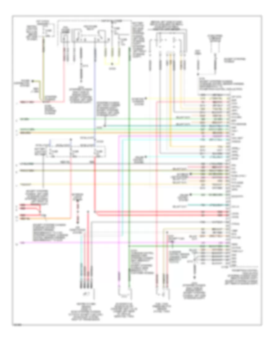
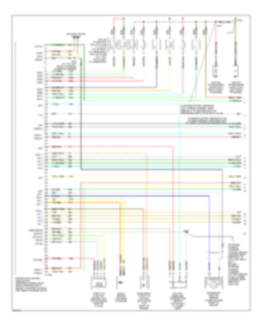
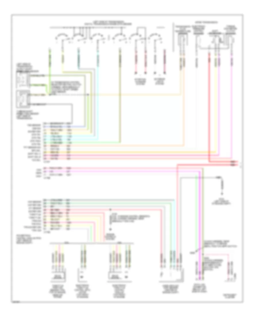
List of elements for 5.4L, Transmission Wiring Diagram, with Torqshift (1 of 2) for Ford Econoline E150 2008:
68
(in engine control sensor & fuel charge harness, near breakout for c192)
(in transmission control selector neutral switch harness, in breakout to right side of transmission)
(in transmission control selector neutral switch harness, near breakout to output shaft speed sensor)
(in transmission control selector neutral switch harness, near breakout to speed sensor assembly)
(right rear of transmission) output shaft speed sensor
(stripped chassis: in main harness, near breakout to inertia fuel shutoff (ifs) switch) (except stripped chassis: in main harness, near breakout to brake pedal position (bpp) switch)
Auxiliary relay box no 1)
Brake pressure switch (left rear of engine compt)
C175b
C175e
C175t
C220a
Can+
Can-
Data link connector (except stripped chassis: below left side of dash) (stripped chassis: behind left side side of dash)
Electronic throttle control motor (5.4l: top front of engine) (6.8l: top left side of engine)
Engine controls system
Feps
G104 (stripped chassis: right side of engine compt) (except stripped chassis: left side of engine compt)
Iat sensor
Instrument cluster
Intermediate shaft speed sensor
Iss sensor
Maf sensor
Mass air flow (maf) sensor (center of engine compt)
Oss sensor
Pc-a sol
Powertrain control module (pcm) (except stripped chassis: left rear of engine compt) (stripped chassis: right rear of engine compt)
Pressure control (pc-a) solenoid
Red
S1037
S123
S139
S172
S198
S269
Shift sol a
Shift sol b
Shift sol c
Shift sol d
Shift sol e
Shift solenoid pressure control a (sspc-a)
Shift solenoid pressure control b (sspc-b)
Shift solenoid pressure control c (sspc-c)
Shift solenoid pressure control d (sspc-d)
Shift solenoid pressure control e (sspc-e)
Sig return
Signal return
Solid state
Speed sensor assembly (left side of transmission)
Tcc sol
Tft sensor
Throttle position sensor (top of engine, near air intake)
Throttle+
Throttle-
Torqshift transmission
Torque converter clutch solenoid
Tps pow
Tps sig return
Tps1 sig
Tps2 sig
Transmission fluid temperature sensor
Transmission range sensor assembly (tr-p)
Trs sensor
Tss sensor
Turbine shaft speed sensor
Vpwr
Vref
5.4L, Transmission Wiring Diagram, with Torqshift (2 of 2) for Ford Econoline E150 2008
List of elements for 5.4L, Transmission Wiring Diagram, with Torqshift (2 of 2) for Ford Econoline E150 2008:
56
(ends in harness)
(except stripped chassis: in engine control sensor harness, near breakout to c140) (stripped chassis: in engine control sensor harness, near breakout to c219) s142
(except stripped chassis: left rear of engine compt) (stripped chassis: left side of engine compt) (6.8l) auxiliary relay box 1
(except stripped chassis: left side of engine compt) (stripped chassis: left front corner of engine compt)
(except stripped chassis: left side of engine compt) (stripped chassis: right side of engine compt)
(in engine control sensor harness, near breakout to powertrain control module (pcm) (w/o stripped chassis) s135
Accelerator pedal position (app) sensor (behind left side of dash, above accelerator pedal)
App1
App2
App3
Appa_+
Appa_-
Appb_+
Appb_-
Battery junction box (bjb) (except stripped chassis: left side of engine compt) (stripped chassis: left front of engine compt)
Battery junction box (bjb) (stripped: left front of engine compt) (except stripped chassis: left side of engine compt)
Bpp sw
Brake pedal position switch (on bracket, above brake pedal)
C175b
Central junction box (behind left side of dash)
Engine controls system
Fuse 10a
Fuse 15a
Fuse 20a
Fuse 30a
G100
G104
G104 (stripped chassis: right side of engine compt) (except stripped chassis: left side of engine compt)
Ground
Hot at all times
Hot in run or start
Kapwr
Nca
O/d off
Od cancel sw
Overdrive cancel switch
Overhead console (if equipped)
Pcm power diode
Pcm power relay
Powertrain control module (pcm) (except stripped chassis: left rear of engine compt) (stripped chassis: right rear of engine compt)
Red
Rev lmp ctrl
Reversing lamp relay
S1021
S1033
S1035
S1065 (except stripped chassis)
S127 (stripped chassis)
S172
S174 (except stripped chassis) (in engine control sensor harness, near breakout to g101)
S216 (w/ remote keyless entry or advance trac)
S260 (w/ advance trac)
S282 (w/ stripped chassis)
Tan
Vpwr
Vss
5.4L, Transmission Wiring Diagram, without Torqshift (1 of 2) for Ford Econoline E150 2008
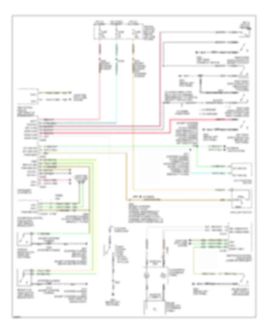
List of elements for Chime Wiring Diagram for Ford Econoline E150 2008:
83
(except stripped chassis) s207
(except stripped chassis: in main harness, near breakout to main light switch) (stripped chassis: in main harness, near breakout to left side of dash)
(in window regulator relay switch harness, near breakout to vehicle security module (vsm)) s253
(stripped chassis) s197
Abs control module (left front of engine compt)
Batt
Brake fluid level switch (left rear of engine compt)
Brk fld led
C1381b
C175b
C218a
C220a
C220b
C310a
C310b
Can +
Can -
Central junction box (cjb) (behind left side of dash)
Clockspring (in steering wheel)
Computer data lines system
Diesel
Door ajar
Driver air bag unit (in steering wheel)
Driver safety belt buckle pretensioner
Drv airbag feed
Drv airbag rtn
Exterior lights system
Fuse 15a
Fuse 20a
Fuse 5a
G113 (stripped chassis) g107 (except stripped chassis) (right front of engine compt)
G204 (behind left kick panel)
G207 (stripped chassis) (behind left end of dash) g203 (except stripped chassis) (behind center of dash)
G400 (left rear corner of vehicle)
Gas
Head
Hot at all times
Hot in run or start
Instrument cluster (ic)
Key in ign
Key in ignition switch
Le turn ind
Left front door ajar switch (behind left kick panel)
Main light switch
Ms can +
Ms can -
Multi-function switch
Nca
Off
Park
Park brk sig
Park brk sw
Park/head
Parking brake switch (near left kick panel)
Powertrain control module (pcm) (left rear of engine compt)
Rear doors door ajar switch (except cutaway)
Red/pnk
Restraints control module (rcm) (under driver's seat)
Rh turn ind
Right front door ajar switch (behind right kick panel)
Right side door ajar switch (front of right side front hinged door)
Right sliding door ajar switch (at right "b" pillar)
Run/acc
S1022
S143 (except stripped chassis)
S206 (except stripped chassis: in main harness, near breakout to instrument cluster) (stripped chassis: in main harness, near breakout to electronic flasher module)
S215
S217 (stripped chassis: in main harness, in breakout to instrument cluster) (except stripped chassis: in main harness, near breakout to c238)
S223
S233
S250
S268 (stripped chassis) (in main harness, near breakout to c238)
S284 (stripped chassis)
S402
Safety belt
Shorting bar
Stripped chassis)
Stripped chassis) s276 (stripped chassis)
Vref
W/ hinged cargo door
W/ sliding cargo door
W/ speaker
W/o speaker
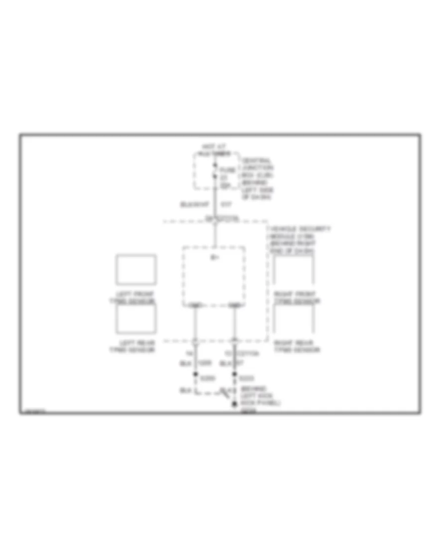
Tire Pressure Monitoring Wiring Diagram for Ford Econoline E150 2008
We use cookies to enhance your browsing experience, serve
personalized ads or content, and analyze our traffic. By clicking "Accept All",
you consent to our use of cookies. Privacy Policy