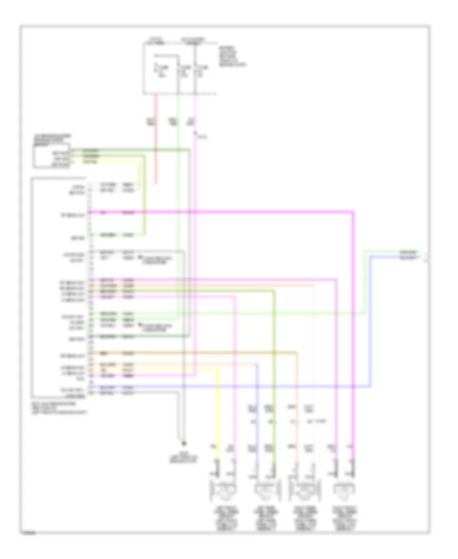
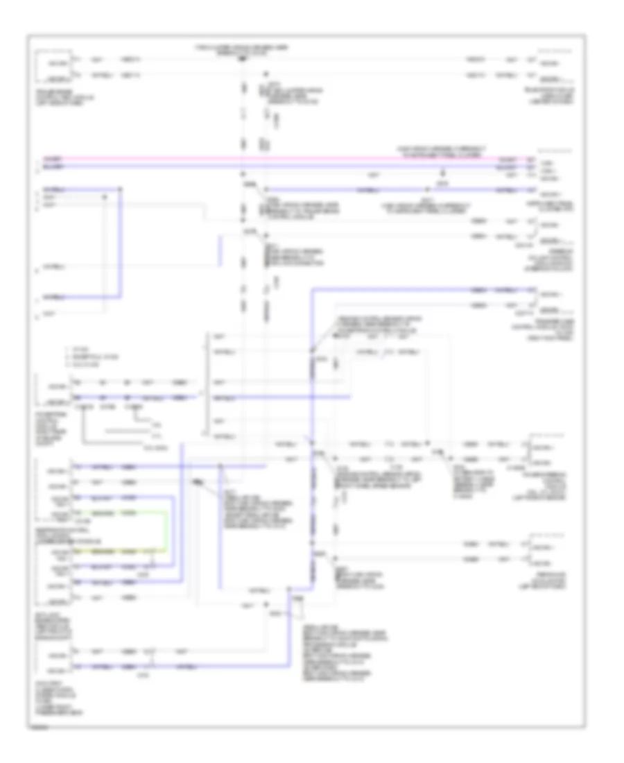
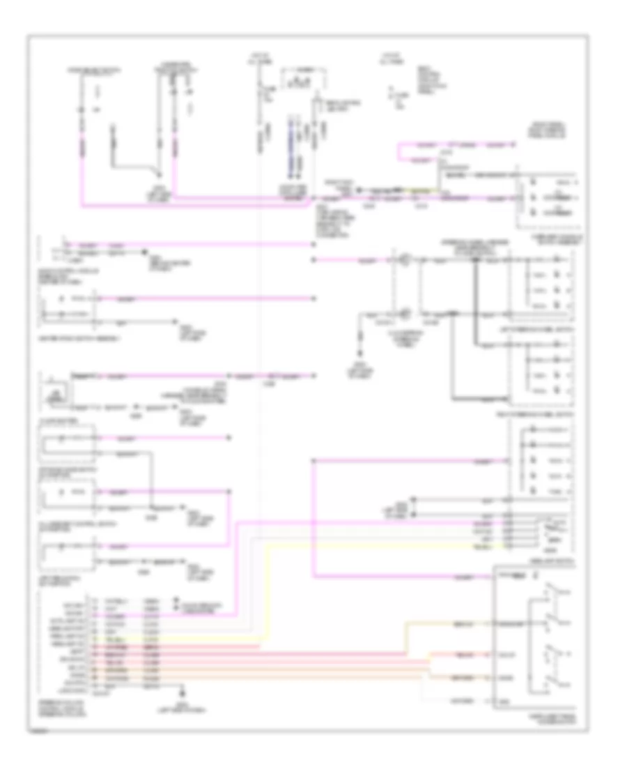
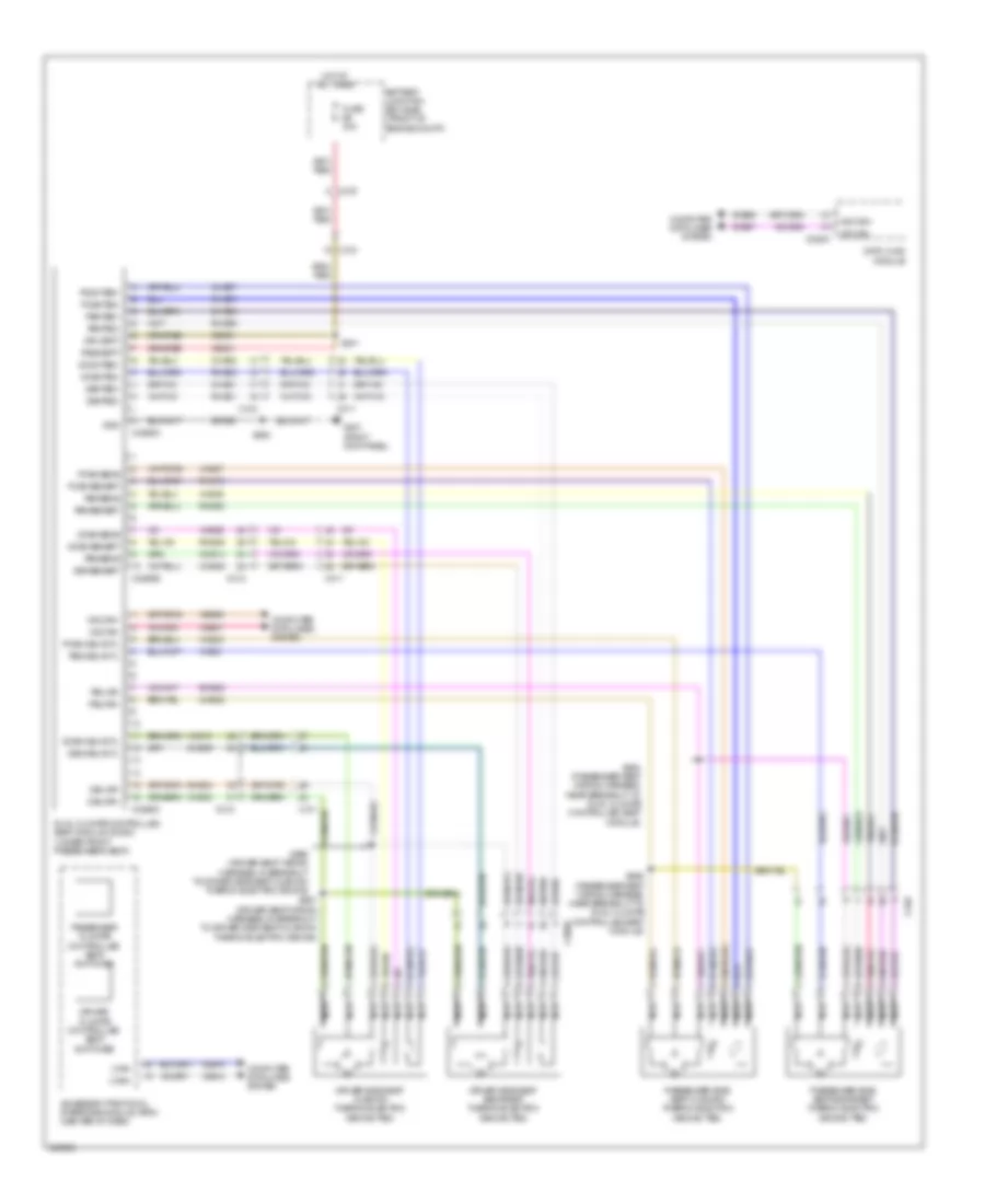
AIR CONDITIONING
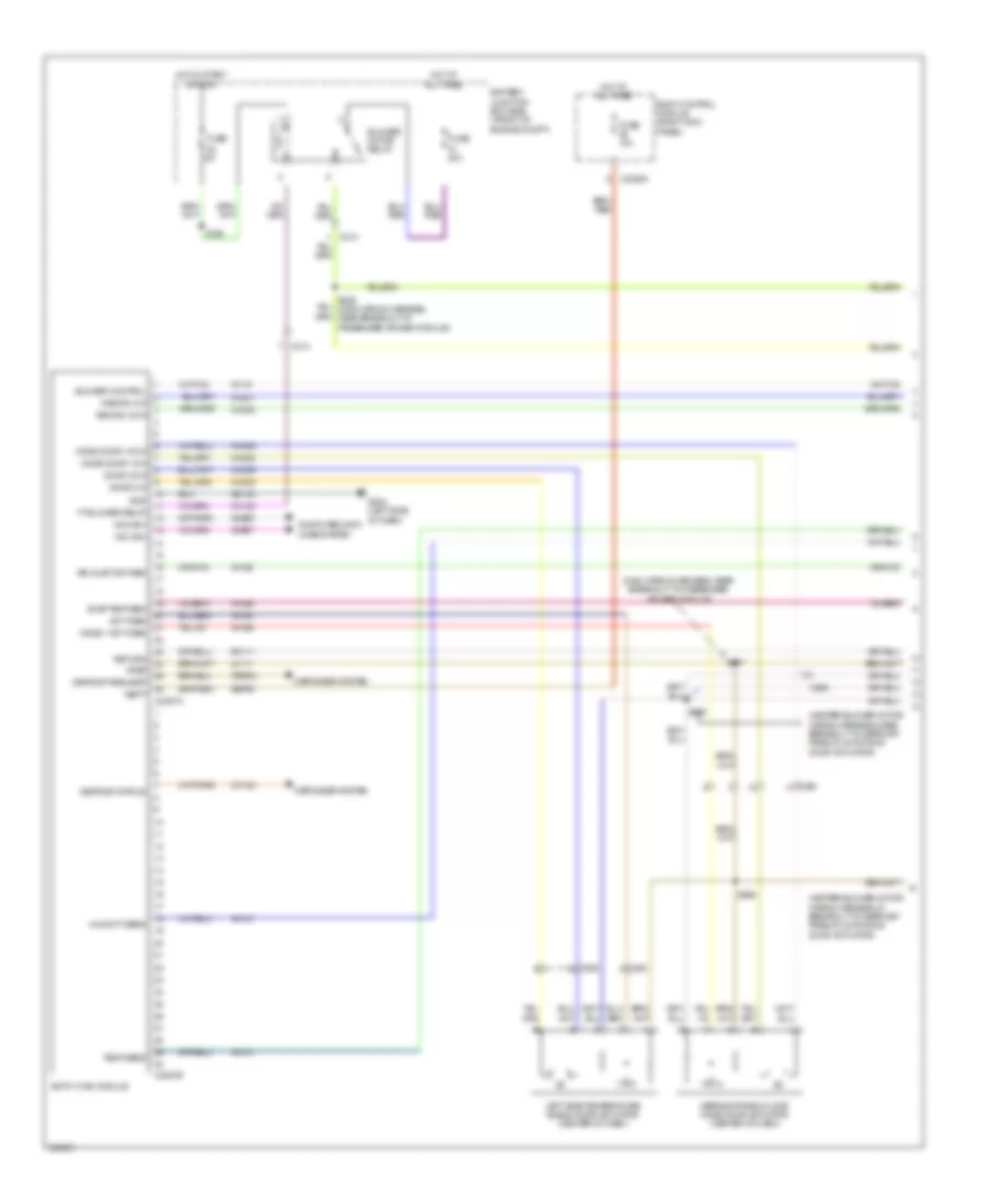
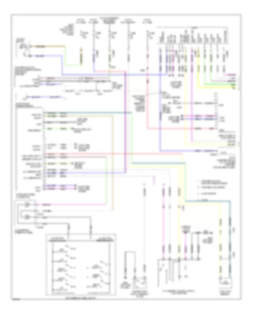
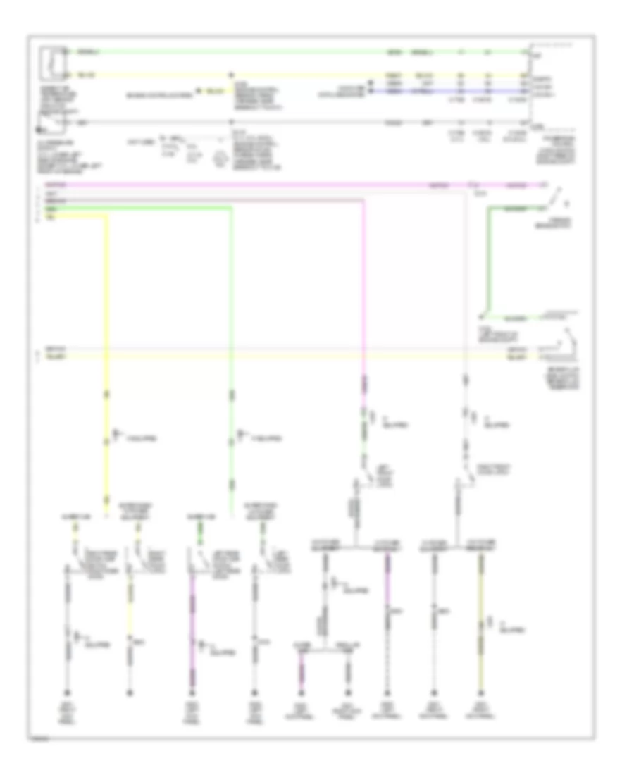
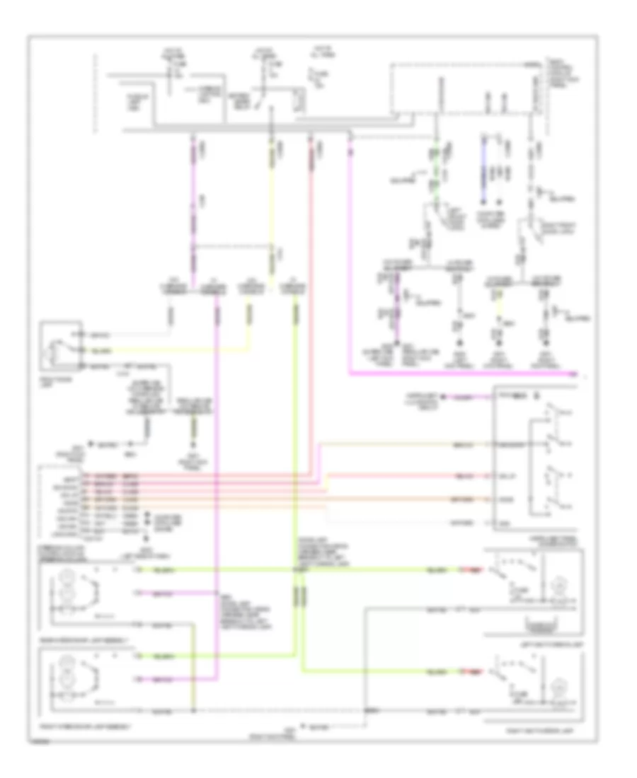
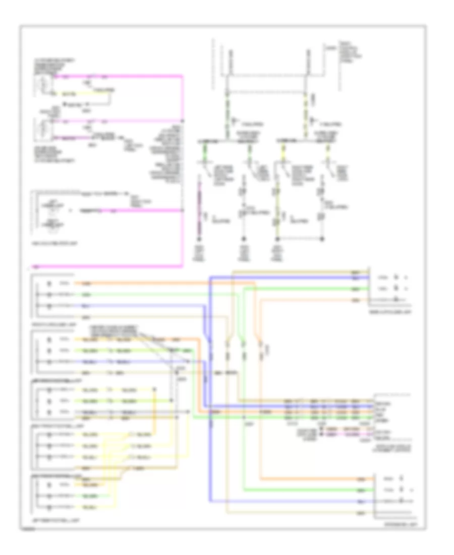
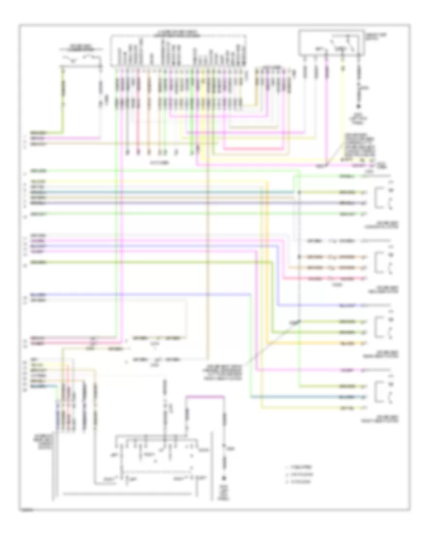
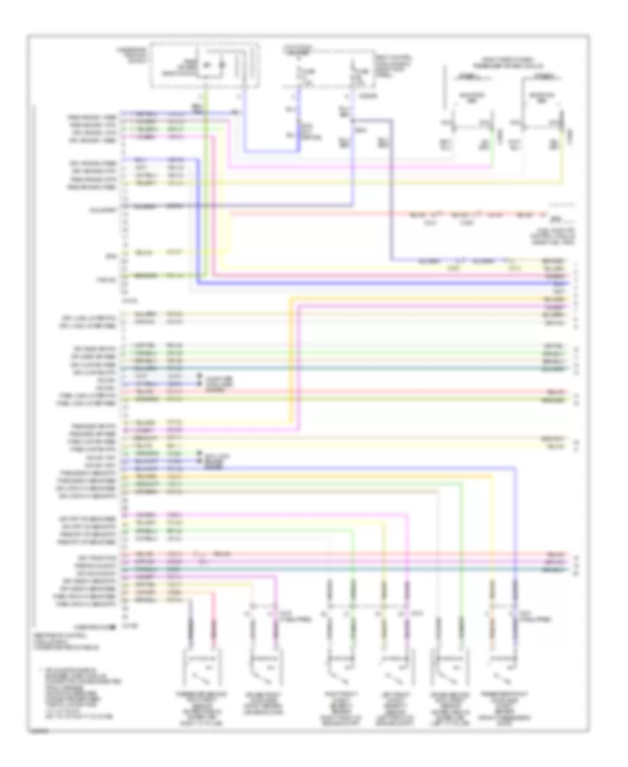
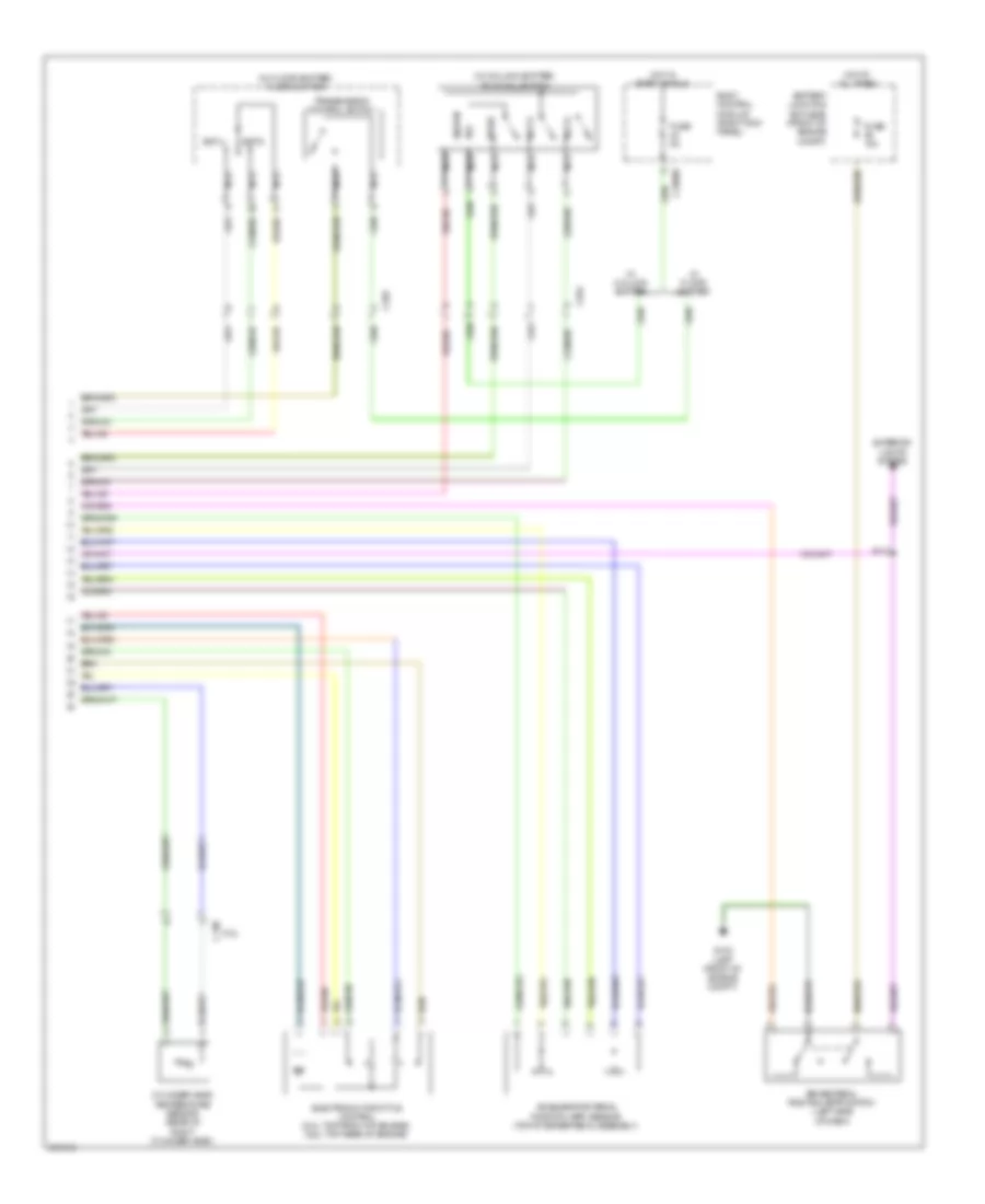
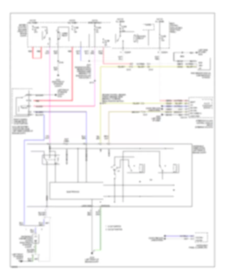
Automatic A/C Wiring Diagram (1 of 3) for Ford F-150 King Ranch 2013

List of elements for Automatic A/C Wiring Diagram (1 of 3) for Ford F-150 King Ranch 2013:
- (left side of dash) g203
- (or ch212)
- (or ch213)
- (or vh441)
- (right side of dash) blower motor
- (w/ ambient lighting)
- 30a
- 40a
- Act fdbk
- Air inlet dr fdbk
- Autolamp sensor in
- Autolamp/sunload sensor (center of dash)
- Battery junction box (bjb) (front of engine compt)
- Blower control
- Blower motor relay
- Blower motor speed control (right side of dash)
- Body control module (right kick panel)
- C213
- C214
- C2280a
- C2280b
- C2280f
- C228a
- C228b
- C260
- C263
- Ch122
- Ch123
- Ch207
- Ch208
- Ch228
- Ch229
- Ch238
- Ch239
- Chs02
- Chs07
- Computer data lines system
- Crd02
- Defogger system
- Defrost request
- Defrost status
- Door ccw
- Door cw
- Driver sunload
- Drv heated st pwr
- Drv heater feed
- Drv st ntc sens
- Eatc hvac module
- Evap temp sen
- Front blower rly
- Fuse
- Fuse 10a
- G202 (left side of dash)
- Gd133
- Gnd
- Hot at all times
- Hot in run or start
- Hs can+
- Hs can-
- Humidity sens
- Left side temperature blend door actuator (center of dash)
- Lh111
- Mode 1 act fdbk
- Mode door 1ccw
- Mode door 1cw
- Motor +
- Motor -
- Ms can+
- Ms can-
- Pass heated st pwr
- Pass heater feed
- Pass st ntc sens
- Pass sunload
- Pwm
- Recirc ccw
- Recirc cw
- Return
- Rh111
- Right side temperature blend door actuator (right side of dash)
- S156
- S222
- S229 (main wiring harness, near breakout to passenger air bag module)
- S260
- S449
- Sbb69
- Sbp46
- Seats system
- Temp sens
- Vbatt
- Vdb04
- Vdb05
- Vdb06
- Vdb07
- Vh101
- Vh406
- Vh413
- Vh414
- Vh416
- Vh417
- Vh436
- Vh438
- Vh440
- Vhs26
- Vhs27
- Vlf14
- Vref
- W/ dual zone
- W/o dual zone
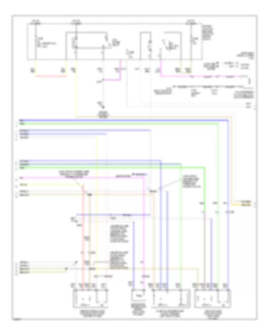
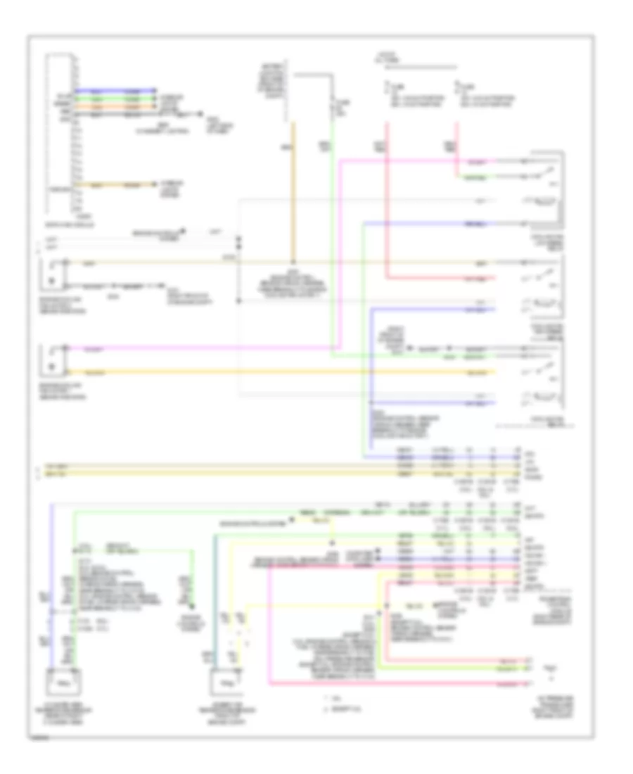
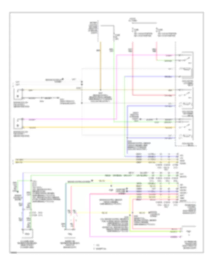
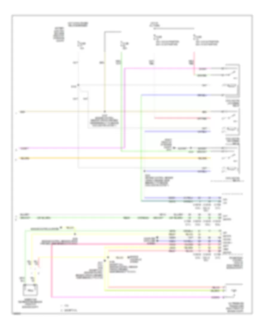
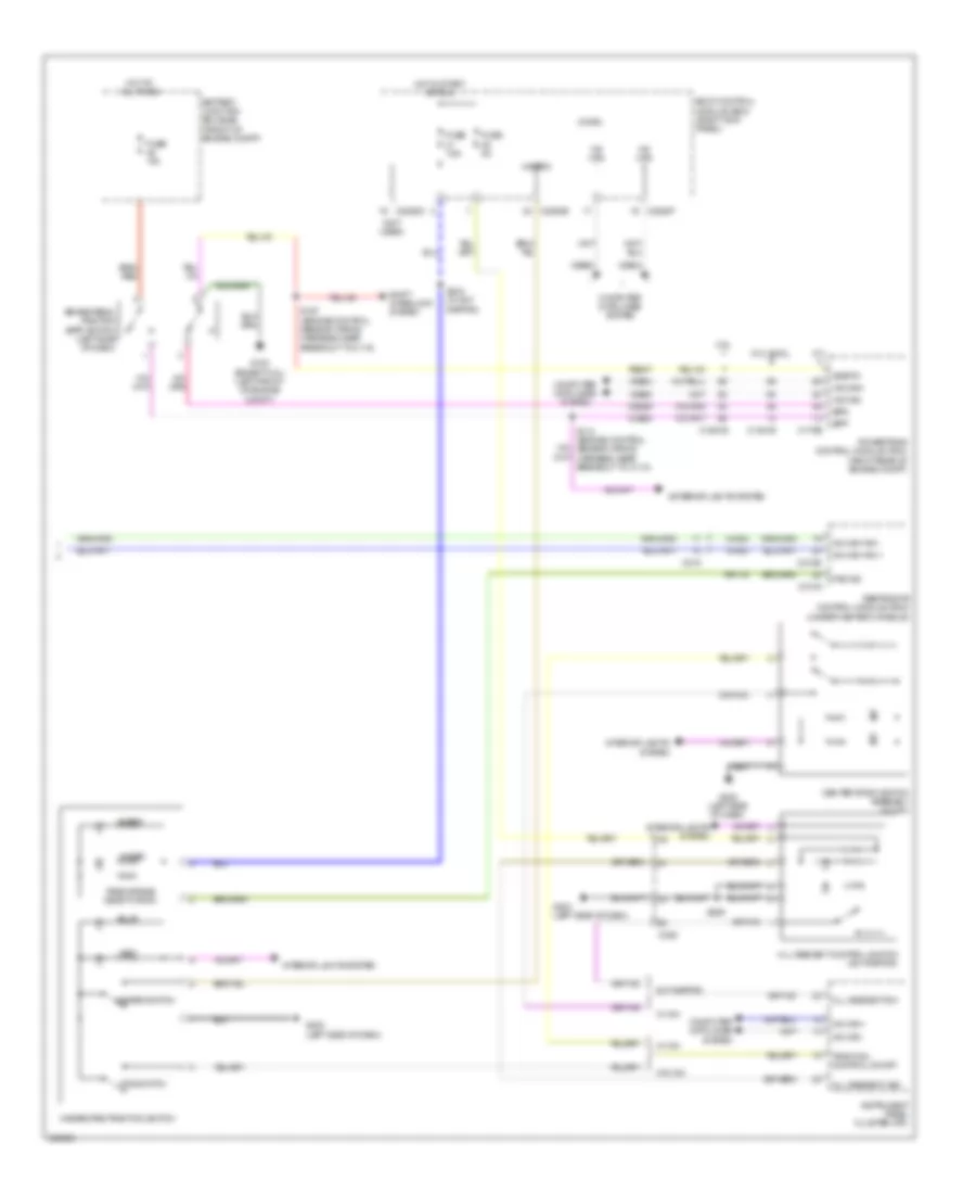
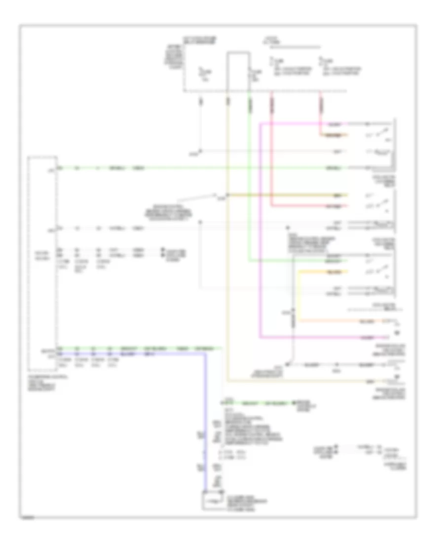
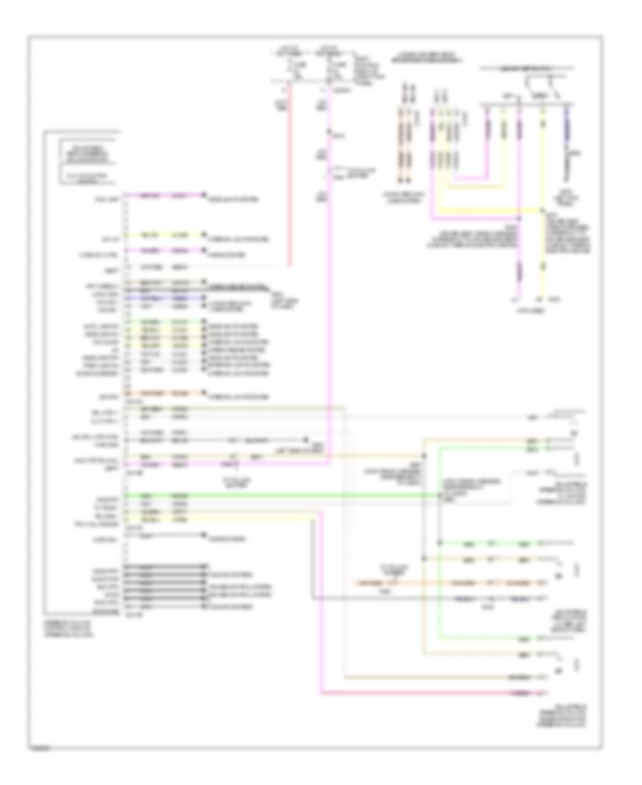
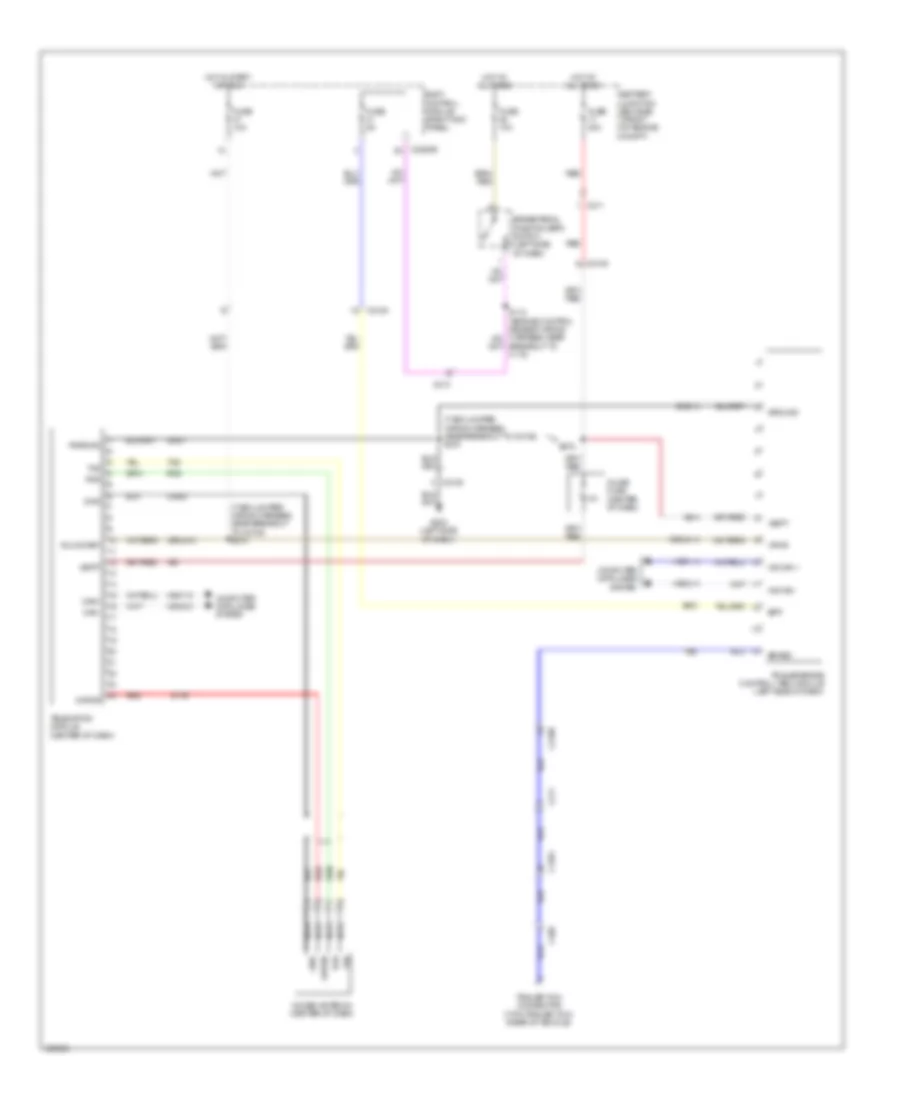
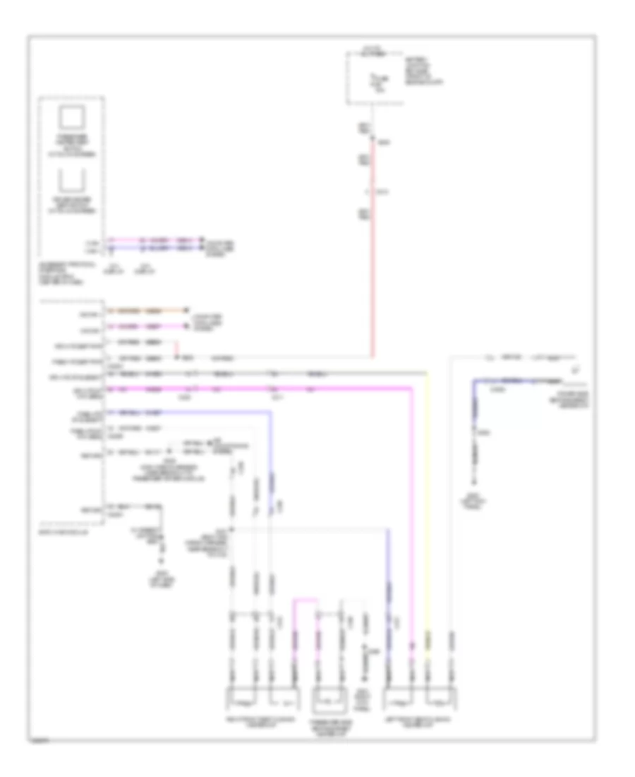
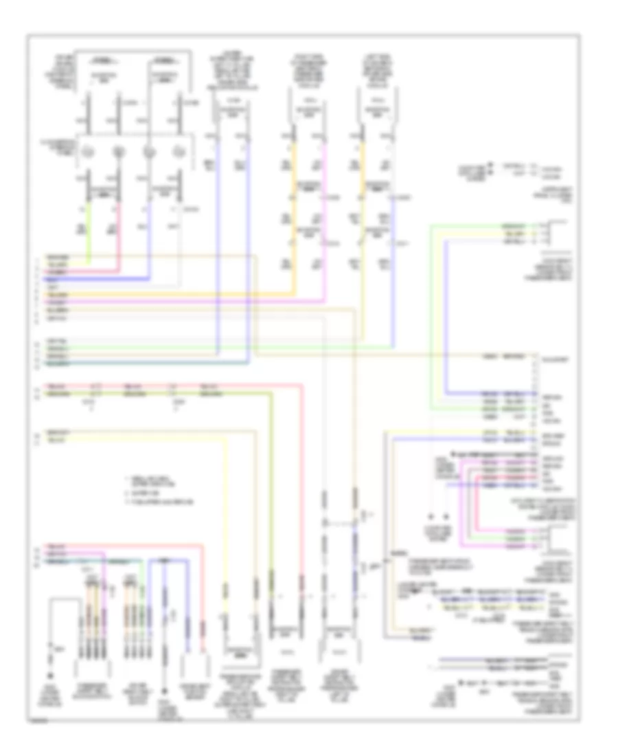
Automatic A/C Wiring Diagram (2 of 3) for Ford F-150 King Ranch 2013
List of elements for Automatic A/C Wiring Diagram (2 of 3) for Ford F-150 King Ranch 2013:
- (3.5l)
- (6.2l)
- (except 3.5l)
- (except 6.2l)
- (heater blower motor wiring harness, in breakout to defrost/panel/ floor mode door actuator)
- (heater blower motor wiring harness, near breakout to defrost/panel/ floor mode door actuator)
- (main wiring harness, near breakout to passenger air bag module)
- (main wiring harness,near breakout to passenger air bag module)
- A/c clutch relay
- A/c compressor clutch field coil (a/c compressor)
- Air inlet mode door actuator (right side of dash)
- Battery junction box (bjb) (front of engine compt)
- C1010
- C192
- C263
- Computer data lines system
- Defrost/panel/floor mode door actuator (center of dash)
- Engine controls system
- Evaporator temperature sensor (right side of dash)
- Fuse 10a
- Fuse 40a 50a
- G101 (right front of engine compt)
- Hot at all times
- Hs can+
- Hs can-
- In-vehicle temperature/ humidity sensor (left side of dash)
- Instrument panel cluster (ipc)
- Pcm power relay
- S125
- S208
- S209
- S228
- S247
- Seats system
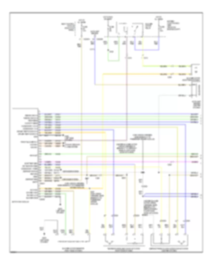
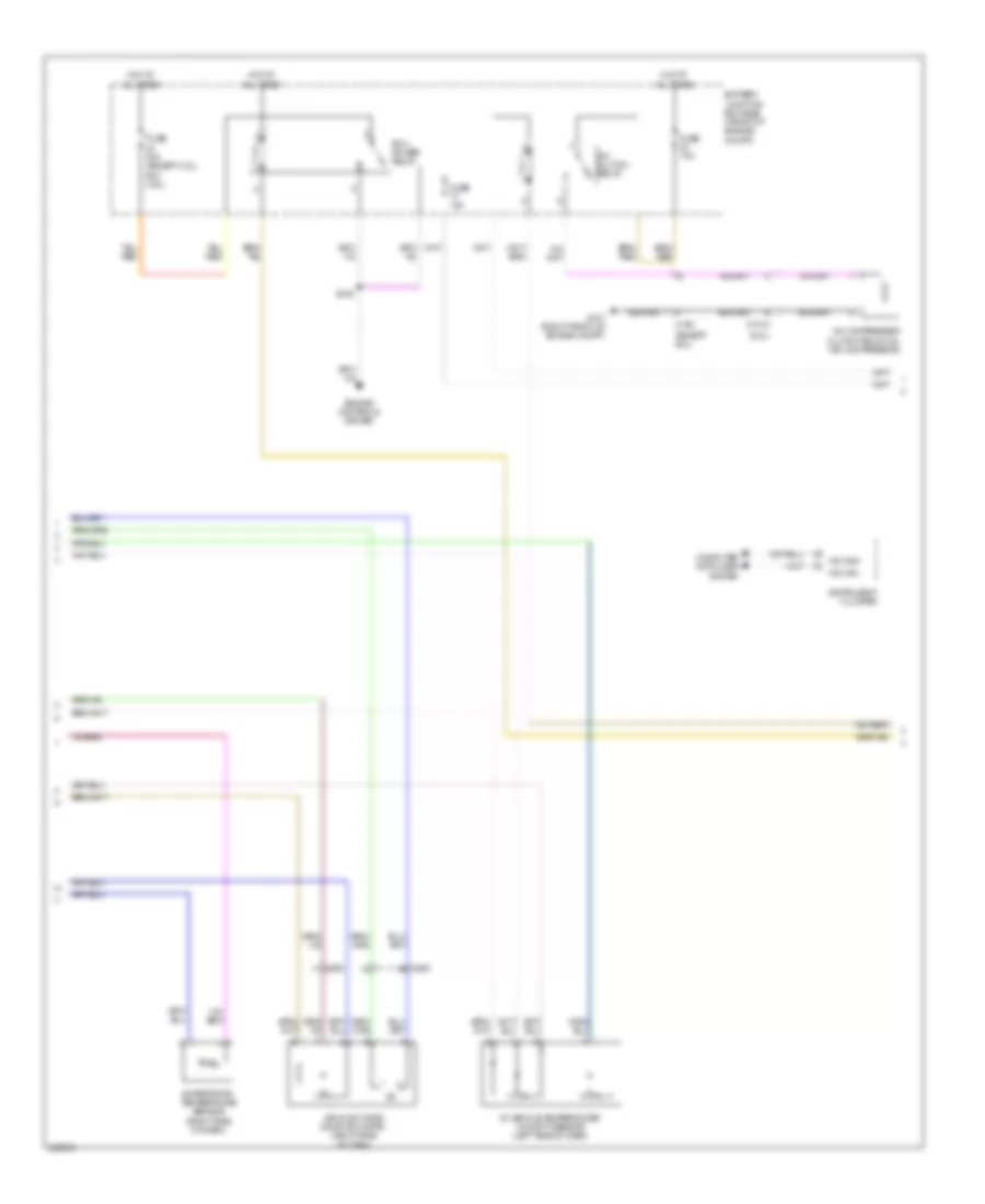
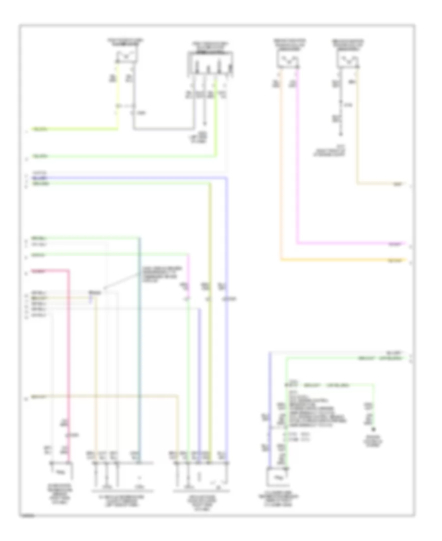
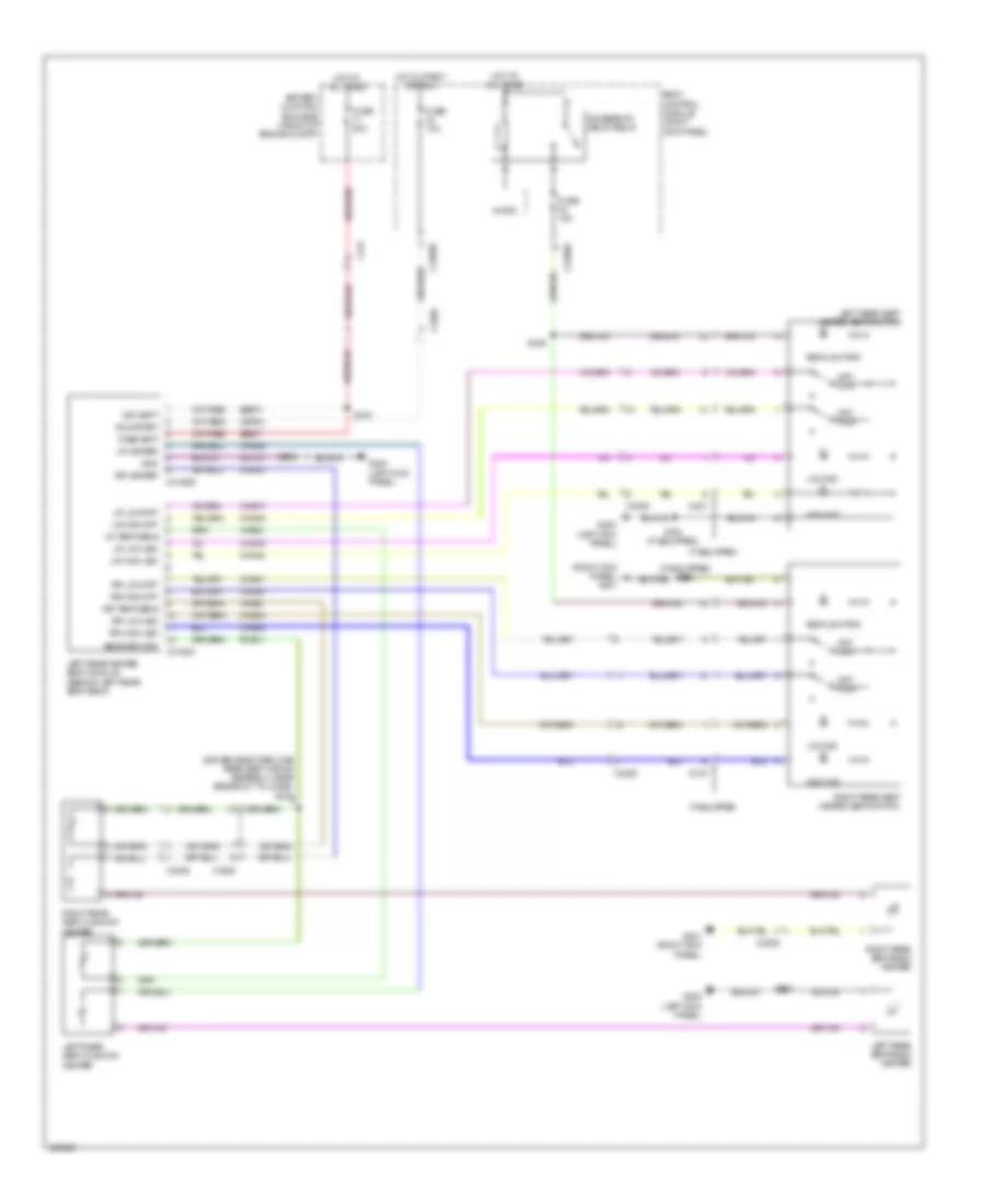
Automatic A/C Wiring Diagram (3 of 3) for Ford F-150 King Ranch 2013
List of elements for Automatic A/C Wiring Diagram (3 of 3) for Ford F-150 King Ranch 2013:
- (3.5l)
- (3.5l) s113
- (3.7l)
- (5.0l & 6.2l)
- (5.0l)
- (6.2l)
- (or re454)
- (right front of of engine compt) g101
- (w/ svt raptor)
- (w/o svt raptor)
- 3.5l
- 50a
- A/c pressure transducer (right front of engine compt)
- Aat
- Accr
- Acpt
- Ambient air temperature sensor (front of engine compt)
- Battery junction box (bjb) (front of of engine compt)
- C1026
- C133
- C1381b
- C1381e
- C1551b
- C1551e
- C175b
- C175e
- C228c
- Ce607
- Cec01
- Cec02
- Ch302
- Cht
- Computer data lines system
- Cooling fan high speed relay
- Cooling fan low speed relay
- Cooling fan relay
- Cylinder head temperature sensor (rear of right cylinder head)
- Eatc hvac module
- Engine controls system
- Engine cooling fan motor 1 (behind radiator)
- Engine cooling fan motor 2 (behind radiator)
- Except 3.5l
- Fuse 25a
- Fuse 40a
- G101 (right front of of engine compt)
- G202 (left side of dash)
- Gd133
- Gnd
- Green
- Hfc
- Hot at all times
- Hs can +
- Hs can -
- Interior lights system
- Le424
- Lfc
- Pcmrc
- Powertrain control module (right rear of engine compt)
- Re405
- Re407
- Red
- Return
- Rln44
- S105
- S141 (3.5l) s162 (except 3.5l) (3.5l: engine control sensor & fuel charge wiring harness, near breakout to fuel rail pressure sensor) (except 3.5l: engine control sensor wiring harness, near breakout to c144)
- S154
- S169 (engine control sensor wiring harness, near breakout to g101)
- S169 (except 3.5l) (engine control sensor wiring harness, near breakout to g101)
- S173 (6.2l & 5.0l) (5.0l:engine control sensor & fuel charge wiring harness, near breakout to c1019) (6.2l: engine control sensor & fuel charge wiring harness, near breakout to c133)
- S183 (engine control sensor wiring harness, near breakout to engine cooling fan motor 1)
- S197 (engine control sensor wiring harness, near breakout to engine cooling fan motor 1)
- S260 (w/ ambient lighting)
- Sig rtn
- Vdb04
- Vdb05
- Ve712
- Ve750
- Vh433
- Vln44
- Vln45
- Vln46
- Vref
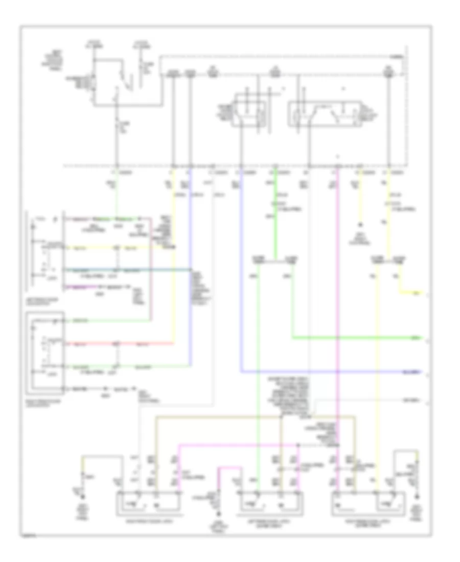
Manual A/C Wiring Diagram, Base (1 of 3) for Ford F-150 King Ranch 2013
List of elements for Manual A/C Wiring Diagram, Base (1 of 3) for Ford F-150 King Ranch 2013:
- (heater blower motor wiring harness, in breakout to defrost/ panel/floor mode door actuator)
- (heater blower motor wiring harness, near breakout to defrost/panel/ floor mode door actuator) s209
- (main wiring harness, near breakout to passenger air bag module)
- Air inlet
- Autolamp sensor (center of dash)
- Autolamp sensor in
- Battery junction box (bjb) (front of engine compt)
- Blower gnd
- Blower motor (right side of dash)
- Blower motor relay
- Blower motor resistor (right side of dash)
- Body control module (right kick panel)
- C213
- C214
- C2280a
- C2280b
- C260
- C263
- C294a
- C294b
- Ch122
- Ch123
- Ch207
- Ch208
- Ch228
- Ch229
- Ch238
- Ch239
- Ch426
- Ch428
- Ch429
- Computer data lines system
- Crd02
- Defogger system
- Defrost req
- Defrost status
- Defrost/panel/floor mode door actuator (center of dash)
- Dr temp dr fdbk
- Driver temp door ccw
- Driver temp door cw
- Emtc hvac module
- Evap temp sen
- Front blower rly
- Fuse 10a
- Fuse 40a
- Fuse 5a
- G202 (left side of dash)
- G203 (left side of dash)
- Gd133
- Gd138
- Gnd
- Hot at all times
- Hot in run or start
- Humidity sens
- Lh111
- Mode door 1 ccw
- Mode door 1 cw
- Mode door 1 fdbk
- Ms can+
- Ms can-
- Recirc dr ccw
- Recirc dr cw
- Return
- Rh111
- S156
- S208
- S227 (main wiring harness, near breakout to passenger air bag module)
- S228
- S247
- Sbp46
- Solid state
- Sw high
- Sw med high
- Sw med low
- Temp sens
- Temperature blend door actuator (right side of dash)
- Vbatt
- Vdb06
- Vdb07
- Vh406
- Vh413
- Vh414
- Vh436
- Vh438
- Vh440
- Vlf14
- Vref
Manual A/C Wiring Diagram, Base (2 of 3) for Ford F-150 King Ranch 2013
List of elements for Manual A/C Wiring Diagram, Base (2 of 3) for Ford F-150 King Ranch 2013:
- (6.2l)
- (except 6.2l)
- A/c clutch relay
- A/c compressor clutch field coil (a/c compressor)
- Air inlet mode door actuator (right side of dash)
- Battery junction box (bjb) (front of engine compt)
- C1010
- C192
- C263
- Computer data lines system
- Engine controls system
- Evaporator temperature sensor (right side of dash)
- Fuse 10a
- Fuse 40a (except 3.5l) 50a (3.5l)
- G101 (right front of engine compt)
- Hot at all times
- Hs can+
- Hs can-
- In-vehicle temperature/ humidity sensor (left side of dash)
- Instrument cluster
- Pcm power relay
- S125
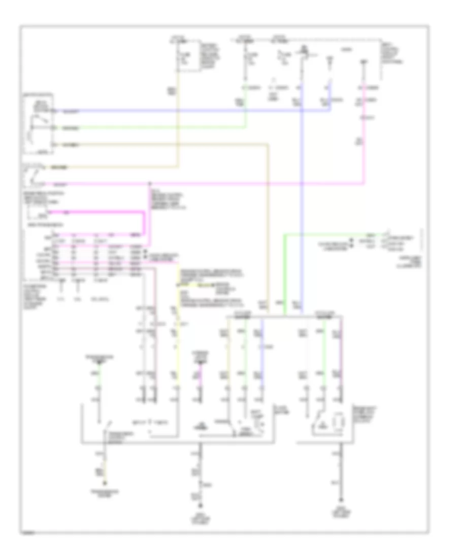
Manual A/C Wiring Diagram, Base (3 of 3) for Ford F-150 King Ranch 2013
List of elements for Manual A/C Wiring Diagram, Base (3 of 3) for Ford F-150 King Ranch 2013:
- (0r re454)
- (3.5l)
- (3.5l) s113 s173 (6.2l & 5.0l) (5.0l: engine control sensor & fuel charge wiring harness, near breakout to c1019) (6.2l: engine control sensor & fuel charge wiring harness, near breakout to c133)
- (3.7l)
- (5.0l & 6.2l)
- (5.0l)
- (6.2l)
- (engine control sensor wiring harness, near breakout to g101)
- (right front of of engine compt) g101
- (w/ svt raptor)
- (w/o svt raptor)
- 3.5l
- 50a
- A/c pressure transducer (right front of engine compt)
- Aat
- Accr
- Acpt
- Ambient air temperature sensor (front of engine compt)
- Battery junction box (bjb) (front of of engine compt)
- C1026
- C133
- C1381b
- C1381e
- C1551b
- C1551e
- C175b
- C175e
- Ce607
- Cec01
- Cec02
- Ch302
- Cht
- Computer data lines system
- Cooling fan high speed relay
- Cooling fan low speed relay
- Cooling fan relay
- Cylinder head temperature sensor (rear of right cylinder head)
- Engine controls system
- Engine cooling fan motor 1 (behind radiator)
- Engine cooling fan motor 2 (behind radiator)
- Except 3.5l
- Fuse 25a
- Fuse 40a
- G101 (right front of of engine compt)
- Hfc
- Hot at all times
- Hs can +
- Hs can -
- Le424
- Lfc
- Pcmrc
- Powertrain control module (right rear of engine compt)
- Re405
- Re407
- S105
- S154
- S162 (3.5l: engine control sensor & fuel charge wiring harness, near breakout to fuel rail pressure sensor) (except 3.5l: engine control sensor wiring harness, near breakout to c144)
- S169
- S169 (except 3.5l) (engine control sensor wiring harness, near breakout to g101)
- S183 (engine control sensor wiring harness, near breakout to engine cooling fan motor 1)
- S197 (engine control sensor wiring harness, near breakout to engine cooling fan motor 1)
- Sig rtn
- Vdb04
- Vdb05
- Ve712
- Ve750
- Vh433
- Vref
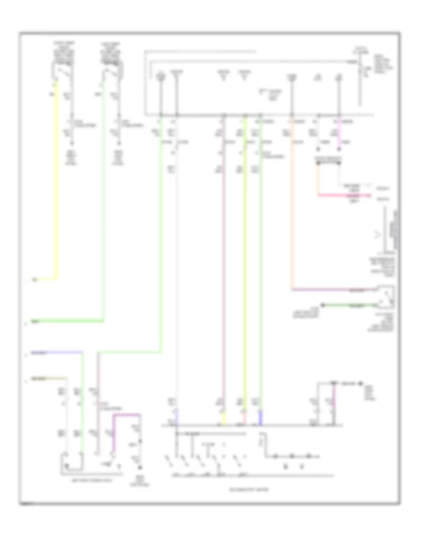
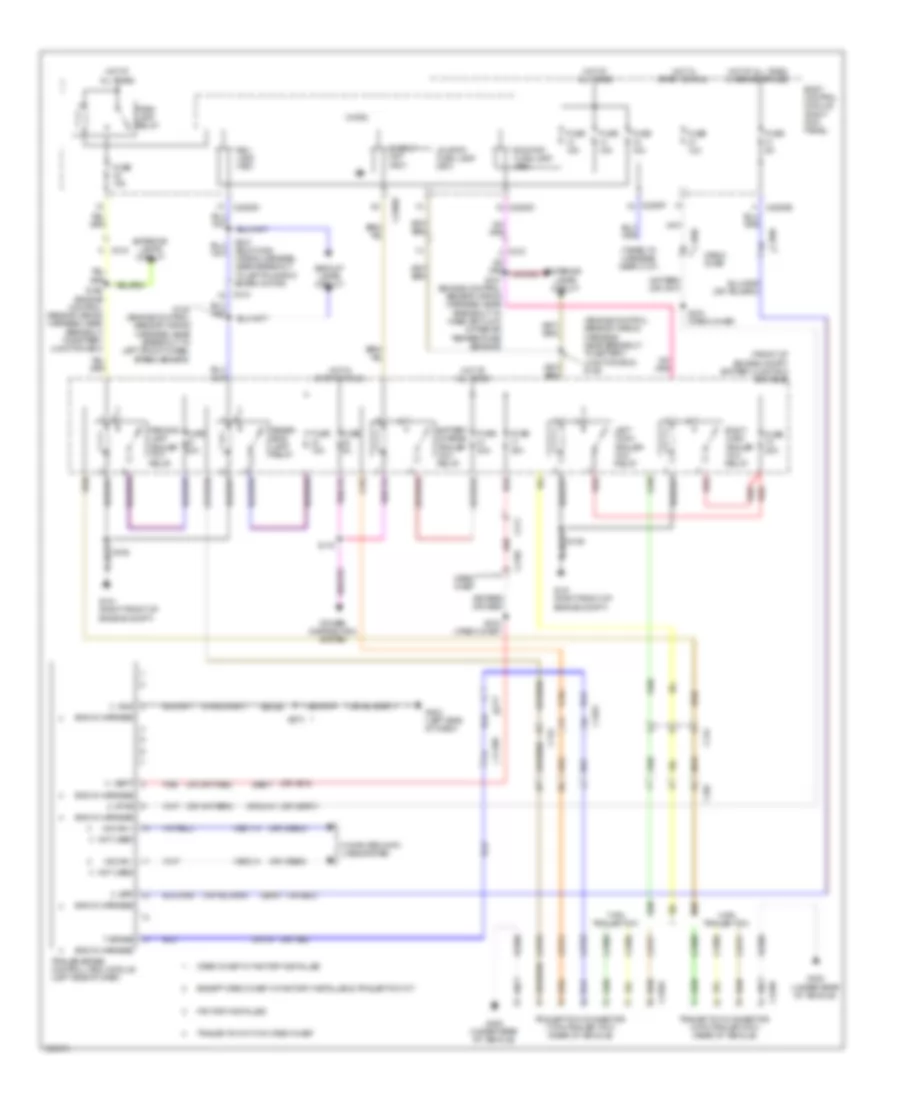
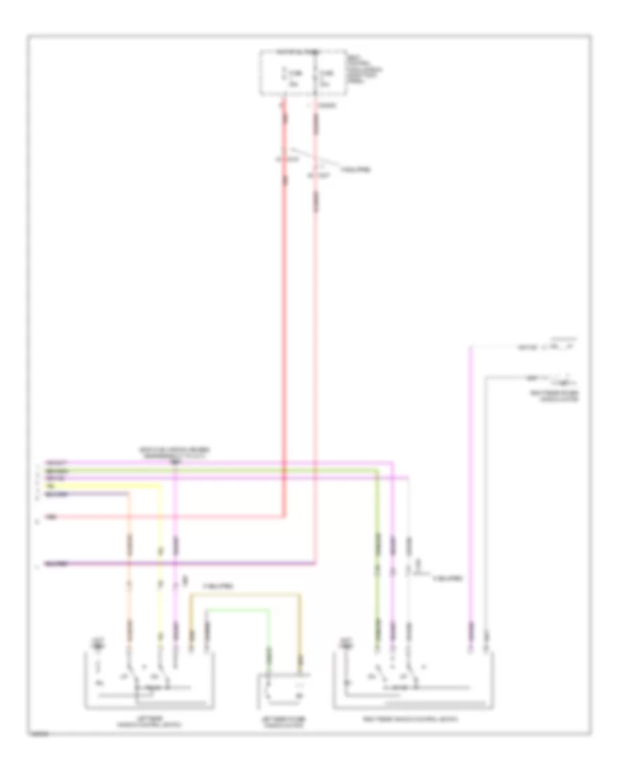
Manual A/C Wiring Diagram, Except Base (1 of 3) for Ford F-150 King Ranch 2013
List of elements for Manual A/C Wiring Diagram, Except Base (1 of 3) for Ford F-150 King Ranch 2013:
- (heater blower motor wiring harness, in breakout to defrost/ panel/floor mode door actuator)
- (heater blower motor wiring harness, near breakout to defrost/ panel/floor mode door actuator)
- (main wiring harness, near breakout to passenger air bag module)
- 40a
- Act fdbk
- Air inlet dr fdbk
- Battery junction box (bjb) (front of engine compt)
- Blower control
- Blower motor relay
- Body control module (right kick panel)
- C213
- C214
- C2280a
- C2357a
- C2357b
- C263
- Ch122
- Ch123
- Ch207
- Ch208
- Ch228
- Ch229
- Ch238
- Ch239
- Computer data lines system
- Crd02
- Defogger system
- Defrost request
- Defrost status
- Defrost/panel/floor mode door actuator (center of dash)
- Door ccw
- Door cw
- Emtc hvac module
- Evap temp sen
- Ft blower relay
- Fuse
- Fuse 10a
- G202 (left side of dash)
- Gd133
- Gnd
- Hot at all times
- Hot in start or run
- Humidity sens
- Left side temperature blend door actuator (center of dash)
- Lh111
- Mode 1 act fdbk
- Mode door 1ccw
- Mode door 1cw
- Ms can+
- Ms can-
- Recirc ccw
- Recirc cw
- Return
- Rh111
- S156
- S208
- S209
- S247
- Sbp46
- Temp sens
- Vbatt
- Vdb06
- Vdb07
- Vh101
- Vh406
- Vh413
- Vh414
- Vh436
- Vh438
- Vh440
- Vref
Manual A/C Wiring Diagram, Except Base (2 of 3) for Ford F-150 King Ranch 2013
List of elements for Manual A/C Wiring Diagram, Except Base (2 of 3) for Ford F-150 King Ranch 2013:
- (3.5l) s113
- (3.7l)
- (6.2l)
- (behind radiator) engine cooling fan motor 1
- (behind radiator) engine cooling fan motor 2
- (main wiring harness, near breakout to passenger air bag module)
- (right side of dash) blower motor
- (right side of dash) blower motor speed control
- Air inlet mode door actuator (right side of dash)
- C1026
- C133
- C260
- C263
- Cylinder head temperature sensor (rear of right cylinder head)
- Engine controls system
- Evaporator temperature sensor (right side of dash)
- G101 (right front of of engine compt)
- G203 (left side of dash)
- Gnd
- In-vehicle temperature/ humidity sensor (left side of dash)
- Motor +
- Motor -
- Pwm
- S154
- S173 (6.2l & 5.0l) (5.0l: engine control sensor & fuel charge wiring harness, near breakout to c1019) (6.2l: engine control sensor & fuel charge wiring harness, near breakout to c133)
- S228
Manual A/C Wiring Diagram, Except Base (3 of 3) for Ford F-150 King Ranch 2013
List of elements for Manual A/C Wiring Diagram, Except Base (3 of 3) for Ford F-150 King Ranch 2013:
- (3.5l)
- (3.7l)
- (5.0l & 6.2l)
- (5.0l)
- (6.2l)
- (or re454)
- (right front of of engine compt) g101
- (w/ svt raptor)
- (w/o svt raptor)
- 3.5l
- 50a
- A/c pressure transducer (right front of engine compt)
- Aat
- Acpt
- Ambient air temperature sensor (front of engine compt)
- Battery junction box (bjb) (front of of engine compt)
- C1381b
- C1381e
- C1551b
- C1551e
- C175b
- C175e
- Cec01
- Cec02
- Cht
- Computer data lines system
- Cooling fan high speed relay
- Cooling fan low speed relay
- Cooling fan relay
- Engine controls system
- Except 3.5l
- Fuse 10a
- Fuse 25a
- Fuse 40a
- Hfc
- Hot at all times
- Hot w/ pcm power relay energized
- Hs can +
- Hs can -
- Le424
- Lfc
- Powertrain control module (right rear of engine compt)
- Re405
- Re407
- S105
- S141 (3.5l) s162 (except 3.5l) (engine control sensor wiring harness, near breakout to c144)
- S154
- S169 (engine control sensor wiring harness, near breakout to g101)
- S169 (except 3.5l) (engine control sensor wiring harness, near breakout to g101)
- S183 (engine control sensor wiring harness, near breakout to engine cooling fan motor 1)
- S197 (engine control sensor wiring harness, near breakout to engine cooling fan motor 1)
- Sig rtn
- Vdb04
- Vdb05
- Ve712
- Ve750
- Vh433
- Vref
ANTI-LOCK BRAKES
Anti-lock Brakes Wiring Diagram (1 of 2) for Ford F-150 King Ranch 2013
List of elements for Anti-lock Brakes Wiring Diagram (1 of 2) for Ford F-150 King Ranch 2013:
- (on brake booster) brake booster sensor
- Anti-lock brake system (abs) module (left front of engine compt)
- Battery junction box (bjb) (front of engine compt)
- Bst gnd
- Bst pwm
- Bst sig
- C1581
- Cbb54
- Cca22
- Computer data lines system
- Fuse 30a
- Fuse 5a
- Fuse 60a
- G103 (left front of engine compt)
- Gd120
- Gd121
- Hot at all times
- Hot in start or run
- Hs can +
- Hs can -
- Hs can yaw +
- Hs can yaw -
- Left front wheel speed sensor (left front wheel hub assembly)
- Left rear wheel speed sensor (left rear wheel hub assembly)
- Lf sens high
- Lf sens low
- Logic gnd
- Lr sens high
- Lr sens low
- Motor gnd
- Mtr b+
- Nca
- Rca17
- Rca18
- Rca19
- Rca20
- Rf sens high
- Rf sens low
- Right front wheel speed sensor (right front wheel hub assembly)
- Right rear wheel speed sensor (right rear wheel hub assembly)
- Rr sens high
- Rr sens low
- Run
- S118
- Sbb36
- Sbb47
- Valve b+
- Vca03
- Vca04
- Vca05
- Vca06
- Vca22
- Vca23
- Vca24
- Vdb04
- Vdb05
Anti-lock Brakes Wiring Diagram (2 of 2) for Ford F-150 King Ranch 2013
List of elements for Anti-lock Brakes Wiring Diagram (2 of 2) for Ford F-150 King Ranch 2013:
- (not used)
- 3.5l
- 3.7l
- 5.0l & 6.2l
- Amber
- Battery junction box (bjb) (front of engine compt)
- Body control module (bcm) (right kick panel)
- Bpp
- Bps
- Brake pedal position (bpp) switch (left side of dash)
- C1381b
- C1551b
- C175b
- C215
- C2280b
- C2280d
- C2280f
- C310a
- C310b
- C329
- Ccb08
- Center stack switch assembly (w/ hmi)
- Ces09
- Computer data lines system
- Exterior lights system
- Fuse 10a
- Fuse 5a
- Fuse 7.5a
- G102 (except 3.5l) (left front of engine compt)
- G202 (left side of dash)
- G203 (left side of dash)
- Hazard
- Hazard switch
- Hazard/pad/traction switch
- Hll descent control switch (svt raptor)
- Hll descent led
- Hll descent sw
- Hot at all times
- Hot in start or run
- Hs can +
- Hs can -
- Hs can yaw +
- Hs can yaw -
- Hs can+
- Hs can-
- Instrument panel cluster (ipc)
- Interior lights system
- Micro
- Pad ind
- Pass air bag deactivation
- Powertrain control module (pcm) (right rear of engine compt)
- Re407
- Red
- Restraints control module (rcm) (under center console)
- Rr116
- S112 (engine control sensor wiring harness, near breakout to c110)
- S167 (engine control sensor wiring harness, near breakout to c110)
- S243 (w/ svt raptor)
- S329
- Shift interlock system
- Sigrtn
- Svt raptor
- Tcs switch
- Traction control on/off
- Vca23
- Vca24
- Vdb04
- Vdb05
- W/ hmi
- W/o hmi
ANTI-THEFT
Forced Entry Wiring Diagram (1 of 2) for Ford F-150 King Ranch 2013
List of elements for Forced Entry Wiring Diagram (1 of 2) for Ford F-150 King Ranch 2013:
- (body main wiring harness, near breakout to c312) s345
- (body main wiring harness, near breakout to g201) s356
- (except super crew: body main wiring harness, near breakout to c238) (super crew: body main wiring harness, near breakout to right running board motor) s301
- (if equipped)
- (if equipped) c316
- Accessory delay relay
- Ajar
- All lock/ unlock relay
- Body control module (right kick panel)
- C219
- C2280c
- C2280d
- C237
- C316
- C327
- Cpk19
- Cpk23
- Cpl31
- Cpl36
- Cpl39
- Door lock
- Door unlock
- Driver door unlock relay
- Fuse 15a
- Fuse 20a
- G200 (left kick panel)
- G201 (right kick panel)
- Hot at all times
- Left front door lock switch
- Left rear door latch (super crew)
- Lock
- Lr door ajar
- Micro
- Rf door ajar
- Right front door latch
- Right front door lock switch
- Right rear door latch (super crew)
- Rr door ajar
- S308
- S355 (body main wiring harness, near breakout to g201)
- S500
- S504 (if equipped)
- S600
- S605 (if equipped)
- S700 (if equipped)
- S800 (if equipped)
- Super cab
- Super crew
- Unlock
Forced Entry Wiring Diagram (2 of 2) for Ford F-150 King Ranch 2013
List of elements for Forced Entry Wiring Diagram (2 of 2) for Ford F-150 King Ranch 2013:
- (if equipped)
- (left rear door) (super cab) left rear door ajar switch
- (right end of dash)
- (right rear door) (super cab) right rear door ajar switch
- 1/2
- 3/4
- 5/6
- 7/8
- 9/10
- Ajar
- Antenna rke receiver internal
- Anti-theft hood switch (left side of engine compt)
- Body control module (right kick panel)
- C219
- C2280b
- C2280c
- C2280f
- C316 (if equipped)
- C327 (if equipped)
- Computer data lines system
- Cpk28
- Cpk29
- Cpk30
- Cpk31
- Cpl25
- Cpl26
- Fuse 10a
- G102 (left front of engine compt)
- G200 (left kick panel)
- G201 (right kick panel)
- Hood ajar
- Hot at all times
- Keyless entry keypad
- Keypad illum (fet)
- Keypad sw a
- Keypad sw b
- Keypad sw c
- Left front door latch
- Lf door ajar
- Micro
- Ms can+
- Ms can-
- Red
- S500
- Tire pressure monitor (tpm) module
- Vdb06
- Vdb07
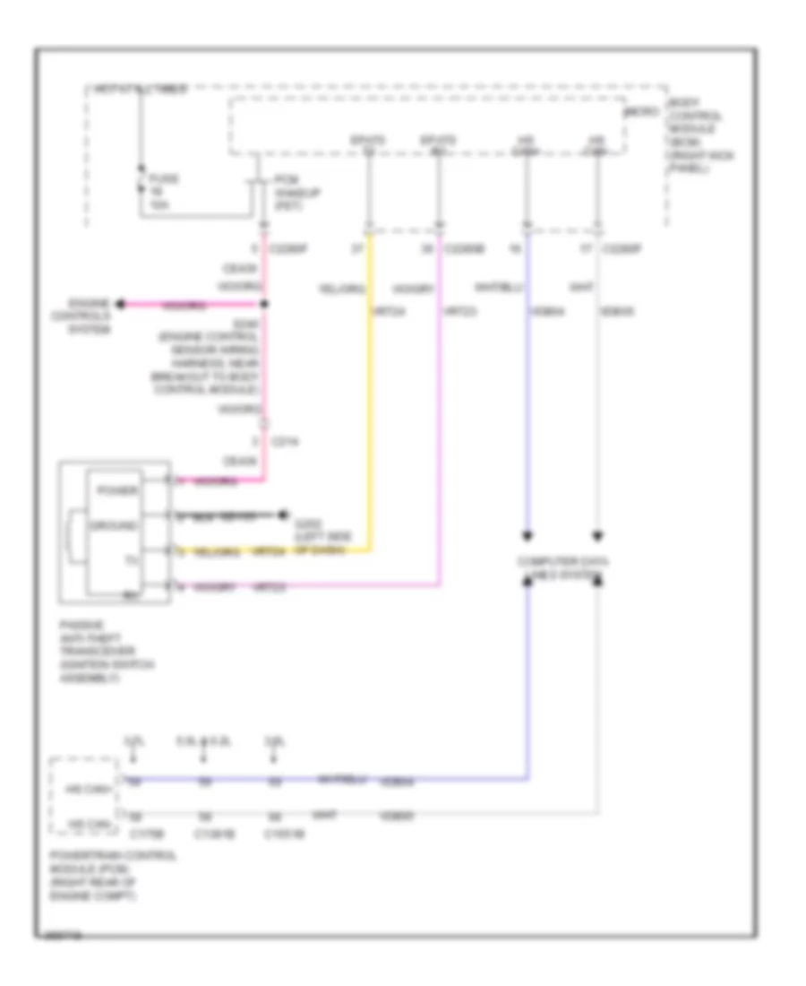
Passive Anti-theft Wiring Diagram for Ford F-150 King Ranch 2013
List of elements for Passive Anti-theft Wiring Diagram for Ford F-150 King Ranch 2013:
- 3.5l
- 3.7l
- 5.0l & 6.2l
- Body control module (bcm) (right kick panel)
- C1381b
- C1551b
- C175b
- C214
- C2280b
- C2280f
- Ce436
- Computer data lines system
- Engine controls system
- Epats rx
- Epats tx
- Fuse 10a
- G202 (left side of dash)
- Gd133
- Ground
- Hot at all times
- Hs can+
- Hs can-
- Micro
- Passive anti-theft transceiver (ignition switch assembly)
- Pcm wakeup (fet)
- Power
- Powertrain control module (pcm) (right rear of engine compt)
- S240 (engine control sensor wiring harness, near breakout to body control module)
- Vdb04
- Vdb05
- Vrt23
- Vrt24
BODY CONTROL MODULES
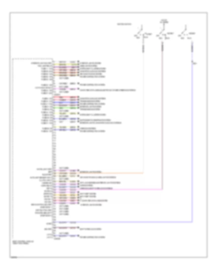
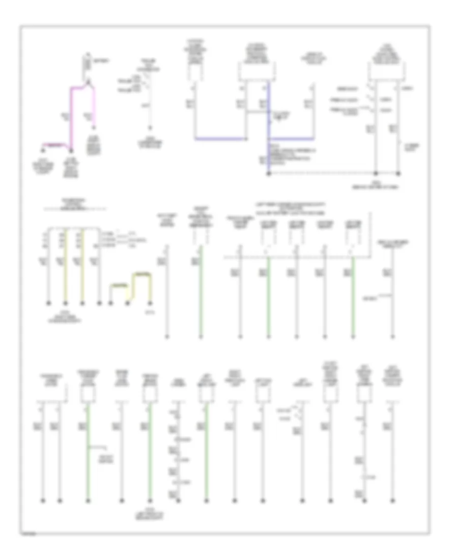
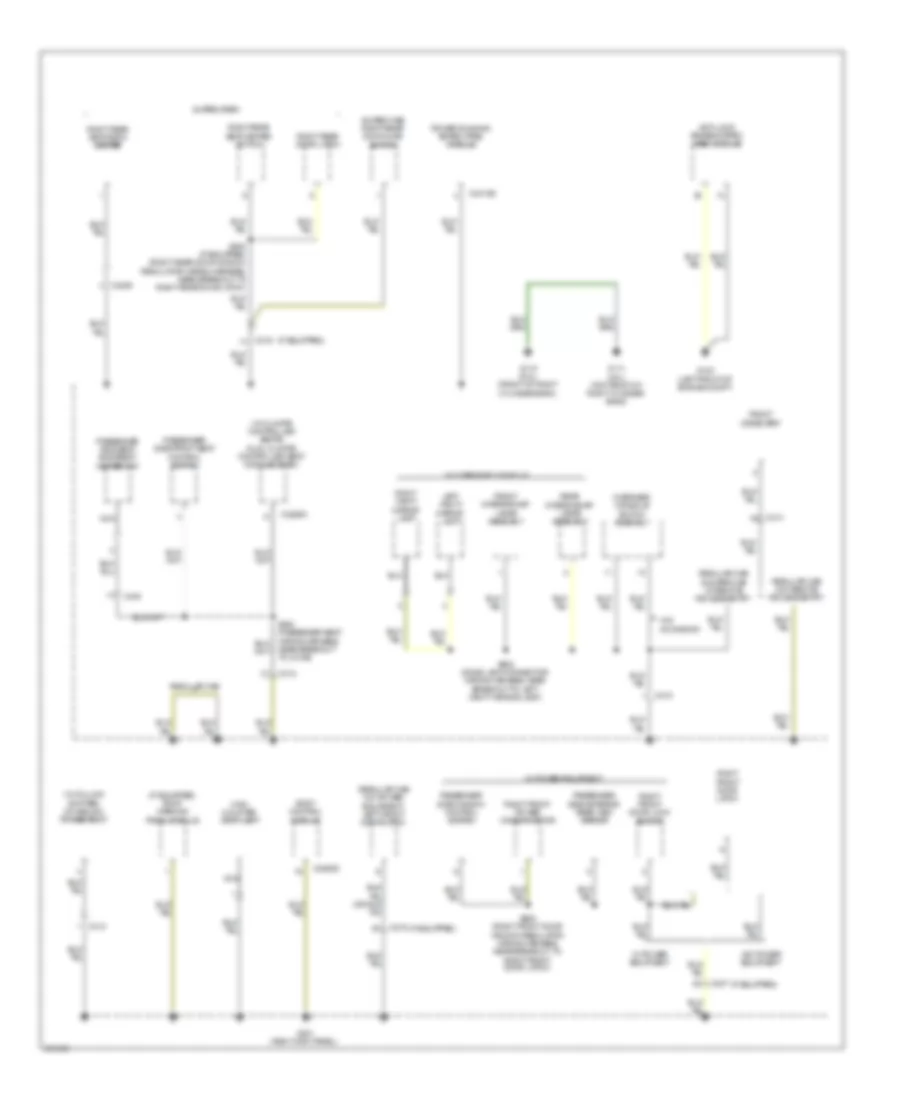
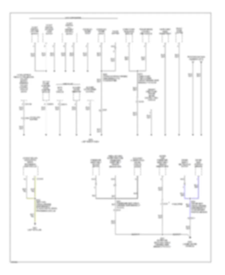
Body Control Modules Wiring Diagram (1 of 2) for Ford F-150 King Ranch 2013
List of elements for Body Control Modules Wiring Diagram (1 of 2) for Ford F-150 King Ranch 2013:
- (not used)
- Acc
- Acc/run
- Air conditioning & headlights systems
- Air conditioning system
- Anti-lock brakes & exterior lights systems
- Anti-theft system
- Autolamp sensor input
- Backlighting led (fet)
- Body control module (right kick panel)
- Bpp
- Bsi (fet)
- C2280a
- C2280b
- Cbp31
- Cbp34
- Cbp35
- Cbp36
- Cbp37
- Cbp38
- Cbp41
- Cbp42
- Ccb08
- Cdc30
- Cdc33
- Cdc34
- Cdc35
- Cet53
- Clf12
- Cls32
- Clutch input
- Computer data lines & electronic power steering systems
- Computer data lines system
- Crh04
- Epats rx
- Epats tx
- Exterior lights system
- Exterior lights, navigation & sound systems
- Fog lamp relay
- Fuse 11, 10a
- Fuse 23, 15a
- Fuse 24, 15a
- Fuse 26, 5a
- Fuse 27, 20a
- Fuse 28, 15a
- Fuse 29, 20a
- Fuse 31, 5a
- Fuse 32, 15a
- Fuse 34, 10a
- Fuse 35, 5a
- Fuse 36, 10a
- Fuse 37, 10a
- Fuse 38, 10a
- Fuse 41, 7.5a
- Fuse 42, 5a
- Fuse 44, 10a
- Fuse 45, 5a
- Fuse 46, 10a
- Fuse 9, 10a
- Hazard sw
- Headlights system
- Horn relay
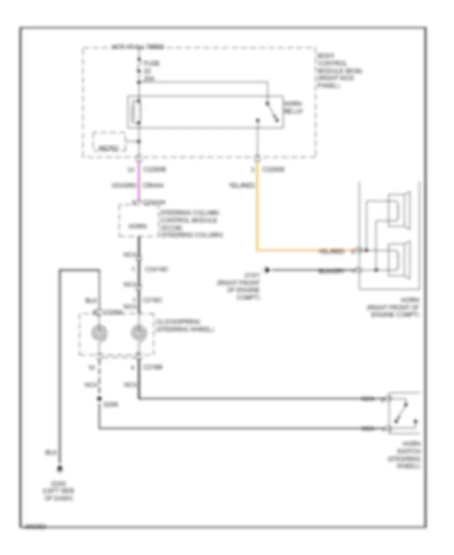
- Horns system
- Hot at all times
- Hot in run or acc
- Ignition switch
- Instrument cluster system
- Interior lighting (fet)
- Interior lights system
- Key in
- Lin 01
- Lin 04
- Ms can +
- Ms can -
- Navigation & sound systems
- Off
- Power distribution system
- Red
- Ripcord security
- Run
- Run/start
- S241
- Sbp09
- Sbp11
- Sbp23
- Sbp24
- Sbp26
- Sbp28
- Sbp29
- Sbp46
- Shift interlock system
- Start
- Start/stop 1
- Start/stop 2
- Strt button (fet)
- Transmissions system
- Vdb06
- Vdb07
- Vdn01
- Vlf14
- Vln04
- Vln33
- Vrt23
- Vrt24
- Warning & shift interlock systems
- Warning systems
- White light (fet)
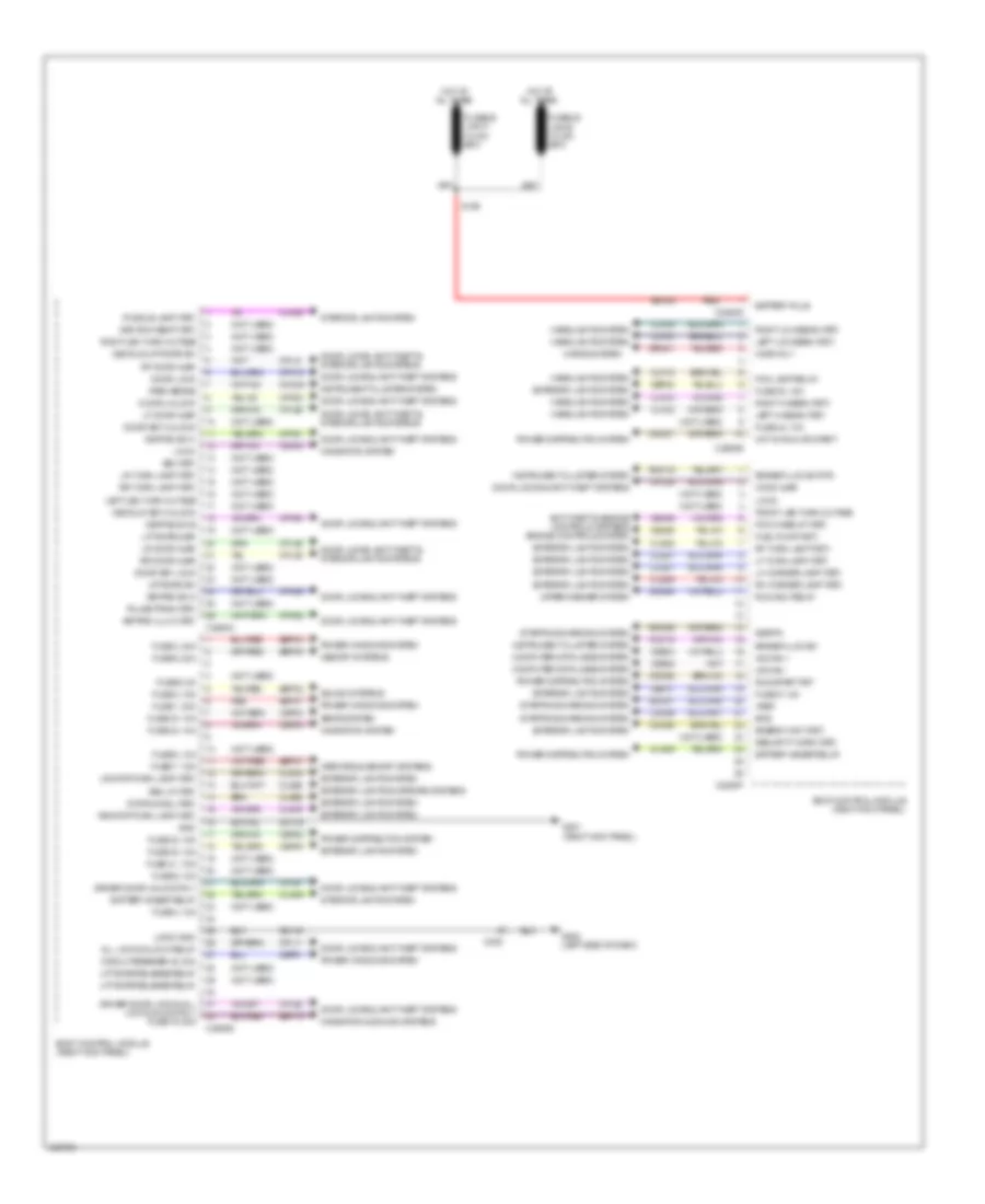
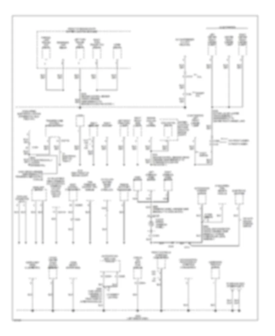
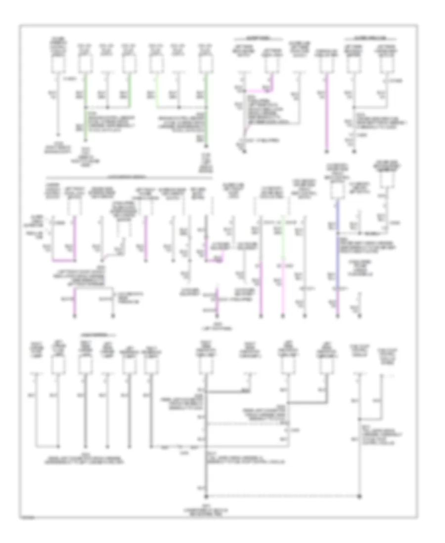
Body Control Modules Wiring Diagram (2 of 2) for Ford F-150 King Ranch 2013
List of elements for Body Control Modules Wiring Diagram (2 of 2) for Ford F-150 King Ranch 2013:
- (not used)
- 3rd row seat (fet)
- All lock/unlock relay
- Anti-theft & engine controls systems engine controls system
- Battery plus
- Battery saver relay
- Bcs
- Body control module (right kick panel)
- Brake fluid sw
- Brake fluid sw rtn
- Bsi (fet)
- C2280c
- C2280d
- C2280e
- C2280f
- C2280g
- C238
- Cbp01
- Cbp30
- Cbp31
- Cbp32
- Cbp33
- Cbp34
- Cbp40
- Cdc21
- Cdc55
- Cdc64
- Cdc66
- Ce226
- Ce436
- Circuit breaker 48, 30a
- Clf02
- Clf03
- Clf04
- Clf05
- Clf12
- Cln09
- Cln25
- Cls18
- Cls19
- Cls21
- Cls25
- Cls28
- Cls52
- Cmc19
- Cmc25
- Computer data lines system
- Cpk19
- Cpk23
- Cpk28
- Cpk29
- Cpk30
- Cpk31
- Cpl11
- Cpl25
- Cpl26
- Cpl31
- Cpl36
- Cpl39
- Cpl51
- Cpl52
- Decklid key unlock
- Decklid/liftgate sw
- Door key lock
- Door key unlock
- Door lock
- Door locks & anti-theft systems
- Door locks, anti-theft & interior lights systems
- Door unlock
- Driver door lock & all lock/unlock rly fuse 19, 20a
- Driver door unlock rly
- Energy mgt (fet)
- Exterior lights & mirrors systems
- Exterior lights system
- Fog lamp relay
- Front led turn outage
- Fuel pump (fet)
- Fuse 1, 30a
- Fuse 2, 15a
- Fuse 3, 30a
- Fuse 30, 15a
- Fuse 31, 5a
- Fuse 32, 15a
- Fuse 33, 10a
- Fuse 34, 10a
- Fuse 4, 10a
- Fuse 40, 10a
- Fuse 41, 7.5a
- Fuse 43, 10a
- Fuse 5, 20a
- Fuse 6, 5a
- Fuse 7, 7.5a
- Fuse 8, 10a
- Fuse 9, 10a
- Fusible link a
- G201 (right kick panel)
- G202 (left side of dash)
- Gd133
- Gd139
- Gnd
- Headlights system
- Hood ajar
- Horn rly
- Horns system
- Hot at all times
- Hot in run or start
- Hs can +
- Hs can -
- Instrument cluster system
- Interior lights system
- Keypad illum (fet)
- Keypad sw a
- Keypad sw b
- Keypad sw c
- Ldc59
- Left hi beam (fet)
- Left led turn outage
- Left low beam (fet)
- Lf door ajar
- Lf turn lamp (fet)
- Lh corner lamp (fet)
- Liftgate ajar
- Liftgate release relay
- Liftgate sw
- Lin 02
- Lin 03
- Logic gnd
- Lr door ajar
- Lr stop/turn lamp (fet)
- Lr turn lamp (fet)
- Memory systems
- Mirrors & memory systems
- Navigation & sound systems
- Navigation system
- Park brake
- Pcm wake up (fet)
- Power distribution system
- Power windows system
- Puddle lamp (fet)
- Pulse train (fet)
- Rdc59
- Red
- Rev lp (fet)
- Rf door ajar
- Rf turn lamp (fet)
- Rh corner lamp (fet)
- Right hi beam (fet)
- Right led turn outage
- Right low beam (fet)
- Rmc19
- Rr door ajar
- Rr stop/turn lamp (fet)
- Rr turn lamp (fet)
- Run/acc relay
- Run/start fet
- S109
- Sbp01
- Sbp02
- Sbp03
- Sbp05
- Sbp07
- Sbp19
- Sdc04
- Sdc57
- Seats system
- Security horn (fet)
- Sigrtn
- Sound systems
- Srh01
- Starting/charging system
- Stop/chmsl (fet)
- Vdb04
- Vdb05
- Vdn03
- Vref
- Wiper/washer system
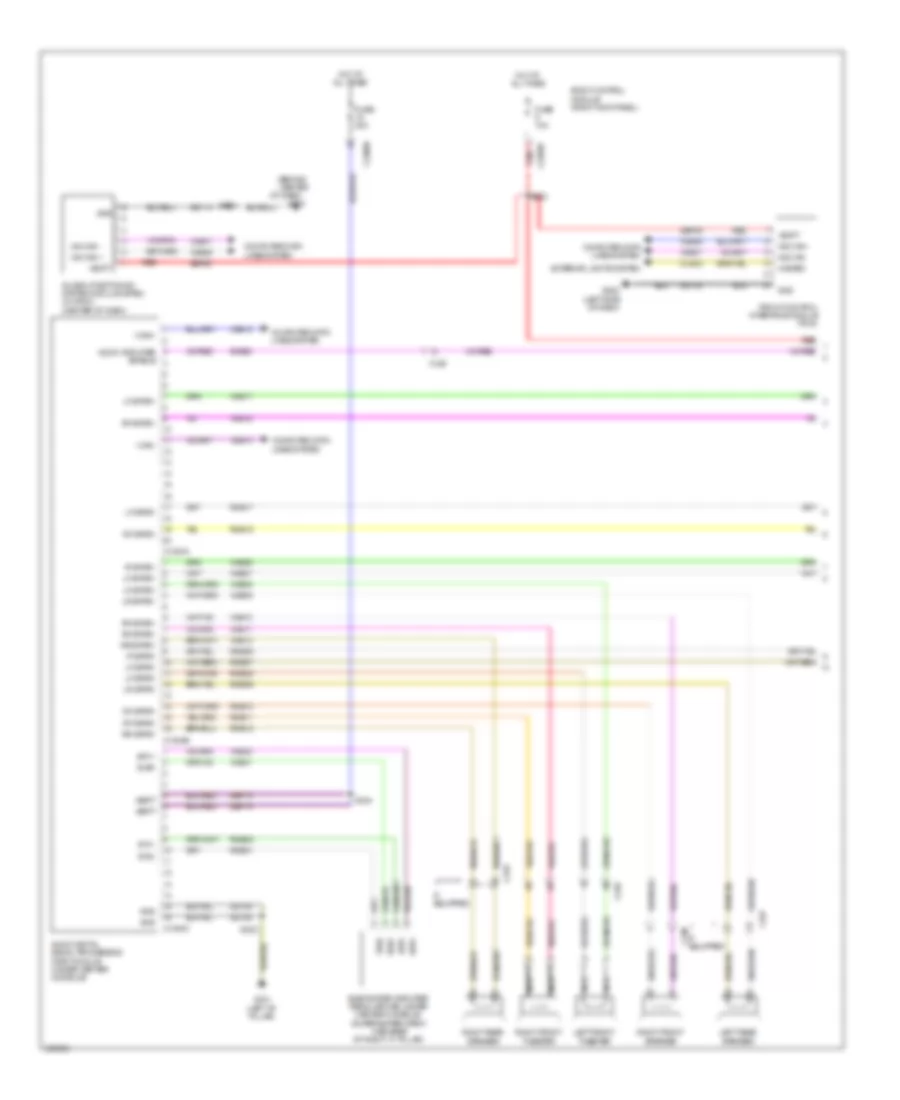
COMPUTER DATA LINES
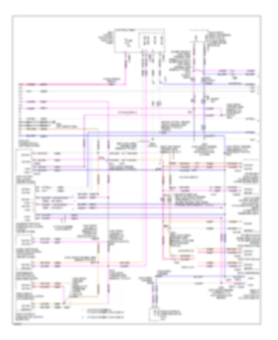
Computer Data Lines Wiring Diagram (1 of 2) for Ford F-150 King Ranch 2013
List of elements for Computer Data Lines Wiring Diagram (1 of 2) for Ford F-150 King Ranch 2013:
- (body main wiring harness, near breakout to c311)
- (body main wiring harness, near breakout to g201)
- (engine control sensor wiring harness, near breakout to c214) (w/sync) s246
- (except super cab: body main wiring harness, near breakout to c312) (super cab: body main wiring harness, near breakout to c313)
- (main wiring harness) s261
- (main wiring harness) s262
- (main wiring harness, in breakout to hazard/pad/ traction switch) s235
- (main wiring harness, near breakout to c213) s219
- (main wiring harness, near breakout to mode select switch)
- (main wiring harness, near breakout to mode select switch) s232
- (main wiring harness, near breakout to passenger air bag module) s239
- (or vdb13)
- (or vdb14)
- (super cab: body main wiring harness, near breakout to c313) vdb14
- (w/ adjustable pedals) s212
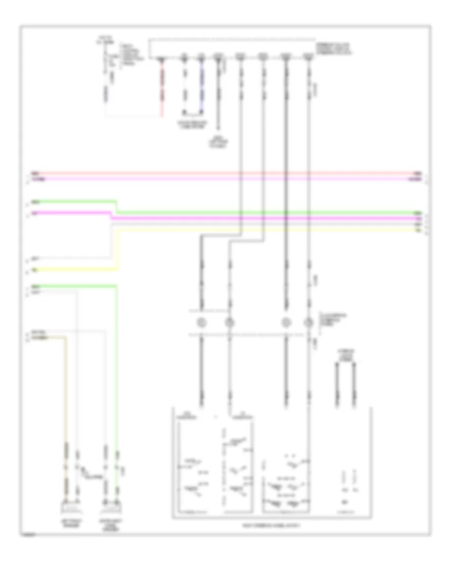
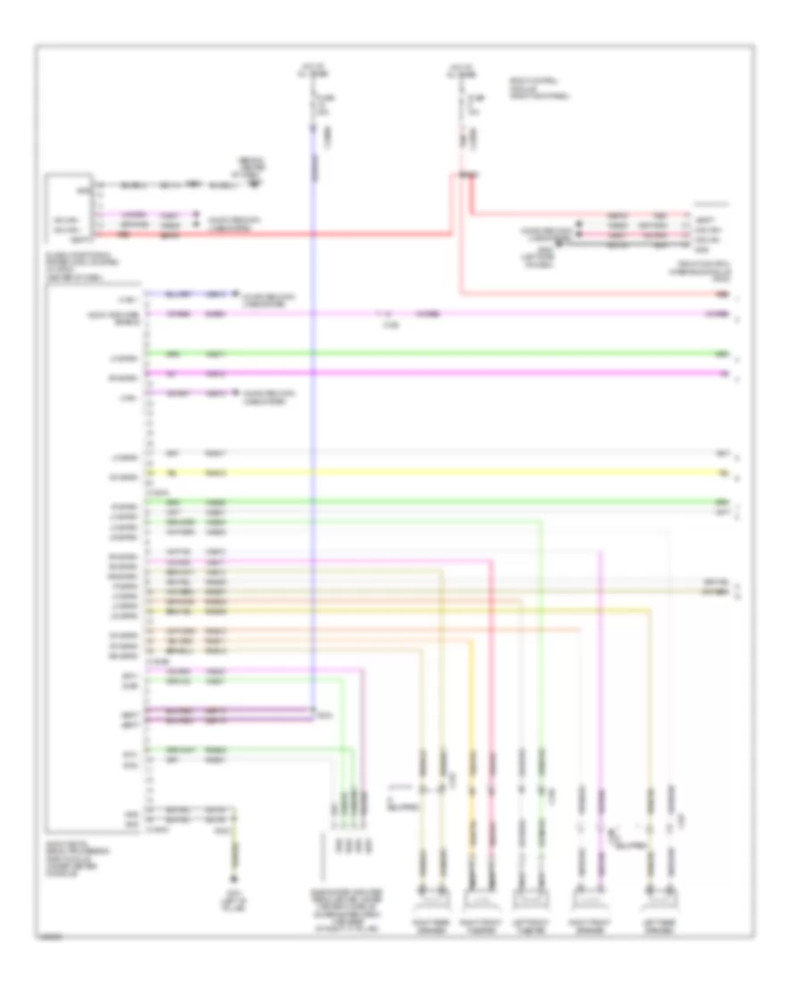
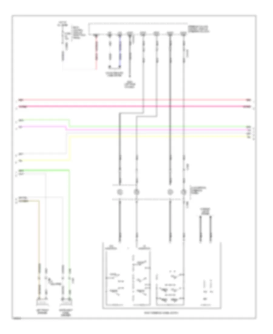
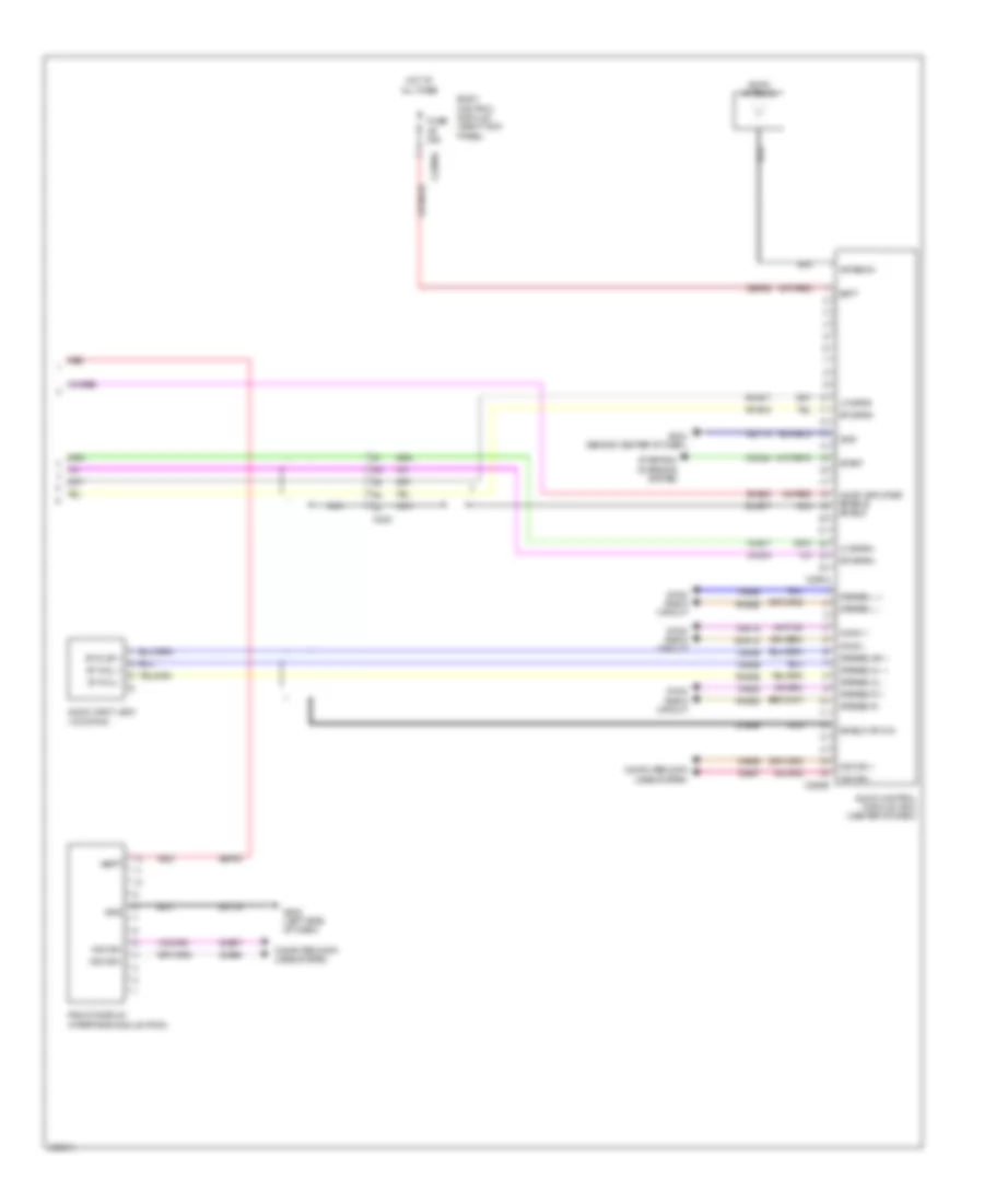
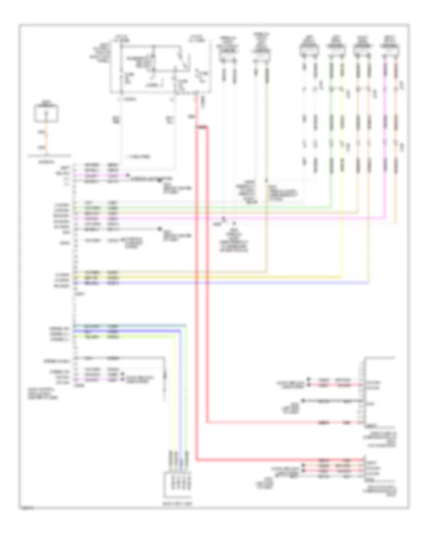
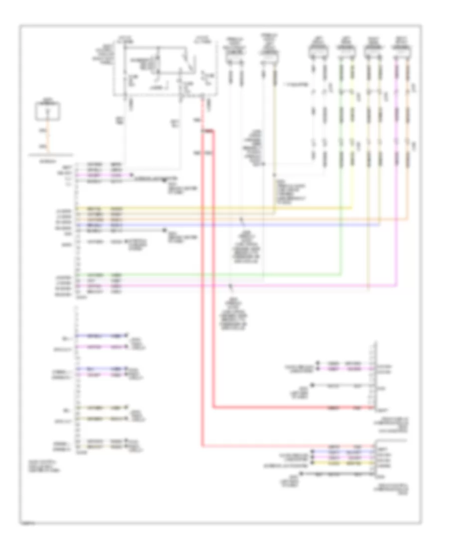
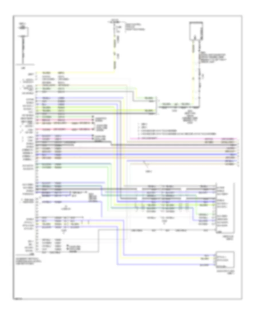
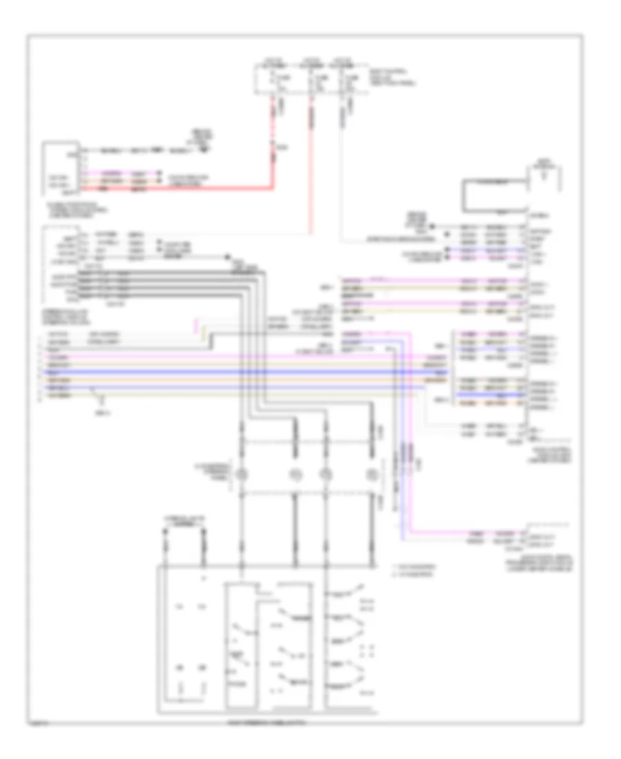
- (w/ sony radio)
- Accessory protocol interface module (apim) (w/ sync) (center of dash)
- Audio control module (acm) (center of dash)
- Audio digital signal processing (dsp) module (w/ sony radio) (under center console)
- Automatic a/c
- Body control module (bcm) (right kick panel)
- C214
- C2280a
- C2280b
- C2280f
- C228a
- C2395
- C240a
- C248
- C290b
- C294a
- C300
- C312
- C3154a
- C3265c
- C3313b
- C341d
- Data link connector (dlc) (left side of dash)
- Datc hvac module
- Driver seat module (dsm) (w/ memory seats) (under driver's seat)
- Dual climate controlled seat module (dcsm) (w/ climate controlled seats) (under front passenger's seat)
- Emtc hvac module
- Except hmi
- Front controls interface module (fcim) (except hmi)
- Front controls interface module (fcim) (hmi)
- Front display interface module (fdim) (w/o navigation)
- Fuse 15a
- G202 (left side of dash)
- Gd133
- Global positioning system module (gpsm) (w/o navigation) (center of dash)
- Head up display (hud) module (w/ 4 inch display)
- Hot at all times
- Hs can +
- Hs can -
- I can +
- I can -
- Manual a/c
- Ms can +
- Ms can -
- Power running board (prb) module (w/ power running boards) (right rear of cab)
- S213
- S214 (main wiring harness, near breakout to g203)
- S218 (main wiring harness, near breakout to c213)
- S225
- S230 (main wiring harness, in breakout to instrument panel cluster)
- S231
- S233
- S245 (w/sync)
- S249
- S250 (main wiring harness, in breakout to autolamp/sunload sensor)
- S318
- S326
- S328
- S335
- Sbp24
- Tire pressure monitor module (right end of dash)
- Vdb04
- Vdb05
- Vdb06
- Vdb07
- Vdb13
- Vdb14
- W/ 8 inch display
- W/ touch screen 4 inch display
- W/ touch screen 8 inch display
- W/o touch screen & w/ touch screen 8 inch display
Computer Data Lines Wiring Diagram (2 of 2) for Ford F-150 King Ranch 2013
List of elements for Computer Data Lines Wiring Diagram (2 of 2) for Ford F-150 King Ranch 2013:
- (engine control sensor wiring harness, near breakout to powertrain control module) s102
- (main wiring harness, in breakout to instrument panel cluster)
- (regular cab: body main wiring harness, near breakout to audio digital signal processing module) (super cab: body main wiring harness, near breakout to c313) (super crew: body main wiring harness, near breakout to c312)
- (t-box jumper wiring harness, near breakout to c2108) s271
- 3.5l
- 3.7l
- 5.0l & 6.2l
- 6.2l w/ 4x2
- Anti-lock brake system (abs) module (left front of engine compt)
- Breakout to trailer brake control module)
- C1381b
- C139
- C1463b
- C1551b
- C175b
- C2108
- C212
- C215
- C2371a
- C2414a
- C248
- C310b
- C312
- Except 6.2l w/ 4x2
- Hs can +
- Hs can -
- Hs can yaw +
- Hs can yaw -
- Hsc1-a
- Hsc1-c
- Hsc2-a
- Hsc2-c
- I can +
- I can -
- Instrument panel cluster (ipc)
- Occupant classification system module (ocsm) (under front passenger's seat)
- Parking aid module (pam) (left end of dash)
- Power steering control module (3.5l, 3.7l & 5.0l) (left side of engine)
- Powertrain control module (right rear of engine compt)
- Restraints control module (rcm) (under center console)
- S100
- S130 (engine control sensor wiring harness, near breakout to left front wheel speed sensor)
- S131
- S152
- S153 (alternator to battery + cable assembly, near breakout to c1463a)
- S204
- S210
- S211 (main wiring harness, near breakout to data link connector)
- S216
- S217 (main wiring harness, in breakout to instrument panel cluster)
- S263
- S317 (regular cab: body main wiring harness, near breakout to g300) (except regular cab: body main wiring harness, near breakout to c313)
- S320
- S323
- S340
- Steering column control module (sccm) (steering column)
- Telematics module (crew chief) (center of dash)
- Trailer brake control (tbc) module (left side of dash)
- Transfer case control module (tccm) (w/ 4x4) (right kick panel)
- Vca23
- Vca24
- Vdb04
- Vdb05
- W/ 4x4
COOLING FAN
Cooling Fan Wiring Diagram for Ford F-150 King Ranch 2013
List of elements for Cooling Fan Wiring Diagram for Ford F-150 King Ranch 2013:
- (3.5l)
- (3.5l) s113
- (3.7l)
- (5.0l & 6.2l)
- (5.0l)
- (6.2l)
- (engine control sensor wiring harness, near breakout to engine cooling fan motor 1)
- (or re454)
- (w/ svt raptor)
- (w/o svt raptor)
- 50a
- Battery junction box (bjb) (front of of engine compt)
- C1026
- C133
- C1381b
- C1381e
- C1551b
- C1551e
- C175b
- C175e
- Cec01
- Cec02
- Cht
- Computer data lines system
- Cooling fan high speed relay
- Cooling fan low speed relay
- Cooling fan relay
- Cylinder head temperature sensor (rear of right cylinder head)
- Engine controls system
- Engine cooling fan motor 1 (behind radiator)
- Engine cooling fan motor 2 (behind radiator)
- Fuse 10a
- Fuse 25a
- Fuse 40a
- G101 (right front of of engine compt)
- Hfc
- Hot at all times
- Hot w/ pcm power relay energized
- Hs can +
- Hs can -
- Hs can+
- Hs can-
- Instrument cluster
- Lfc
- Powertrain control module (right rear of engine compt)
- Re405
- S105
- S154
- S173 (6.2l & 5.0l) (5.0l:engine control sensor & fuel charge wiring harness, near breakout to c1019) (6.2l: engine control sensor & fuel charge wiring harness, near breakout to c133)
- S183 (engine control sensor wiring harness, near breakout to engine cooling fan motor 1)
- S197
- Sig rtn
- Vdb04
- Vdb05
- Ve712
CRUISE CONTROL
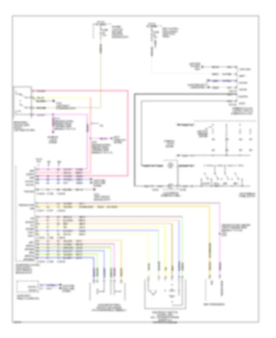
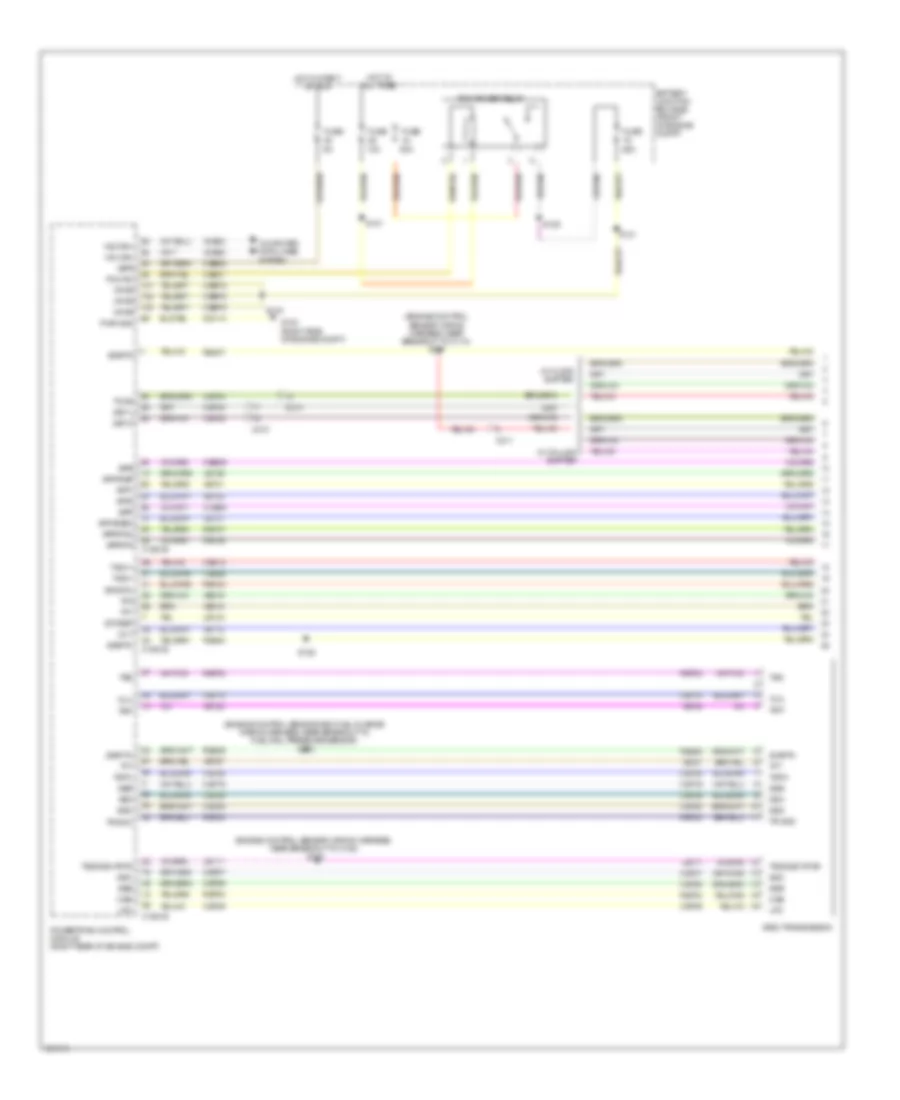
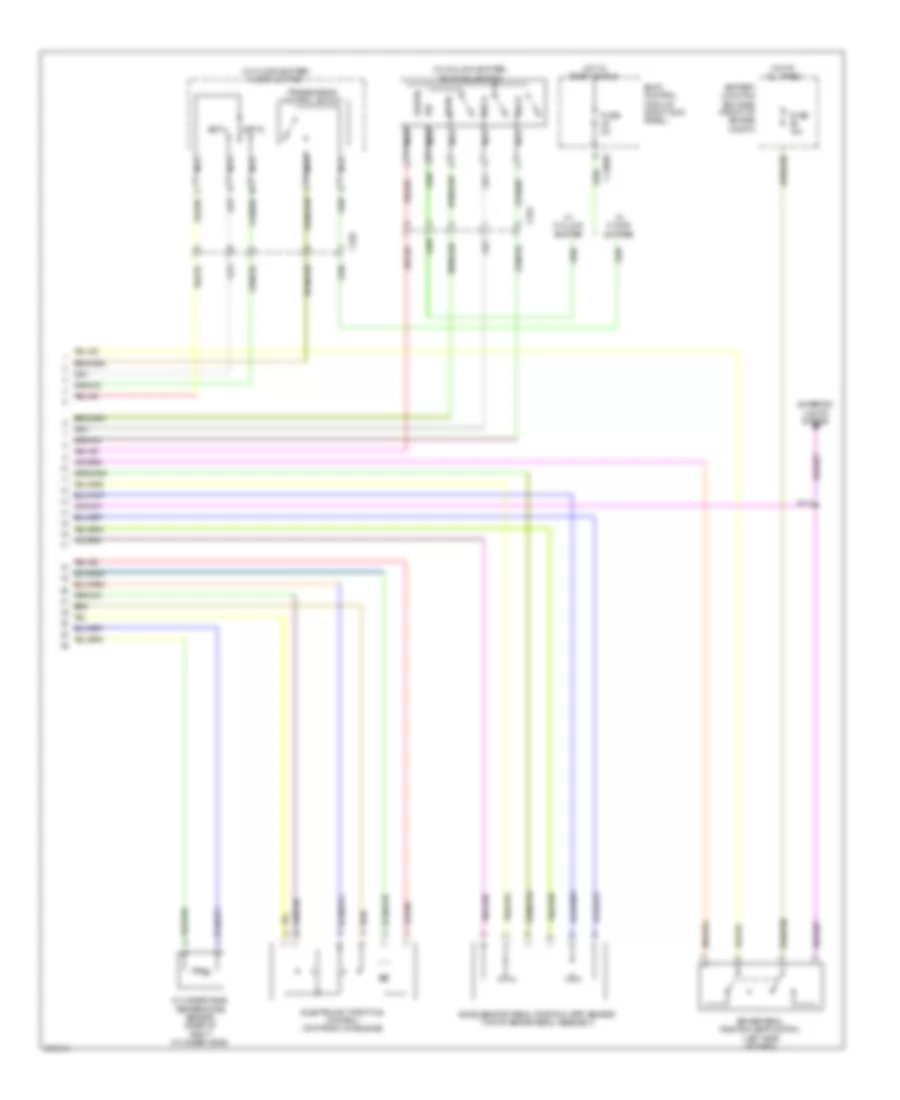
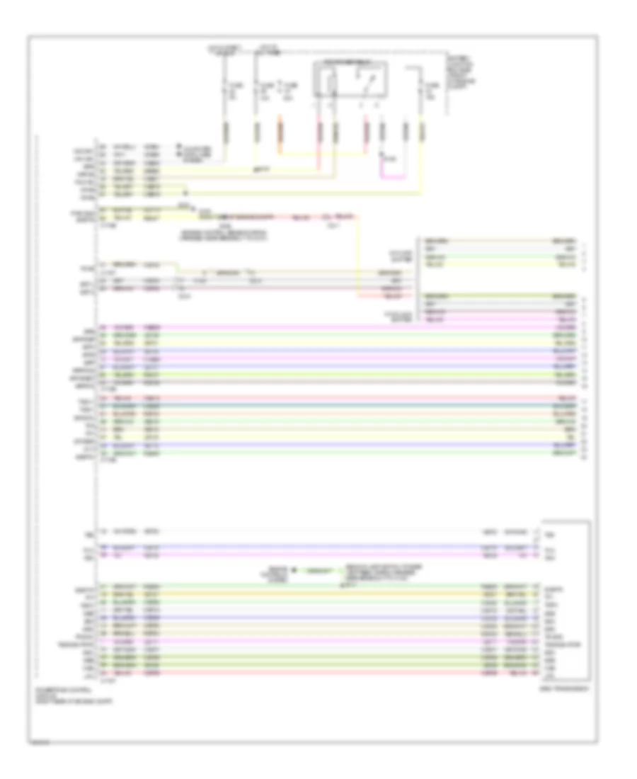
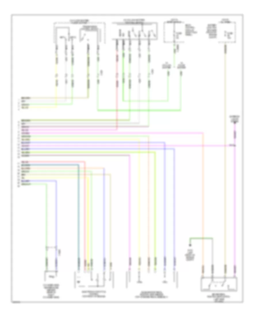
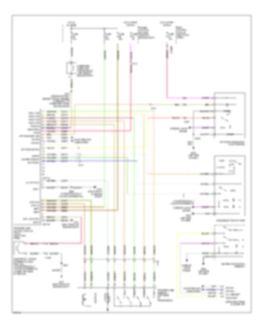
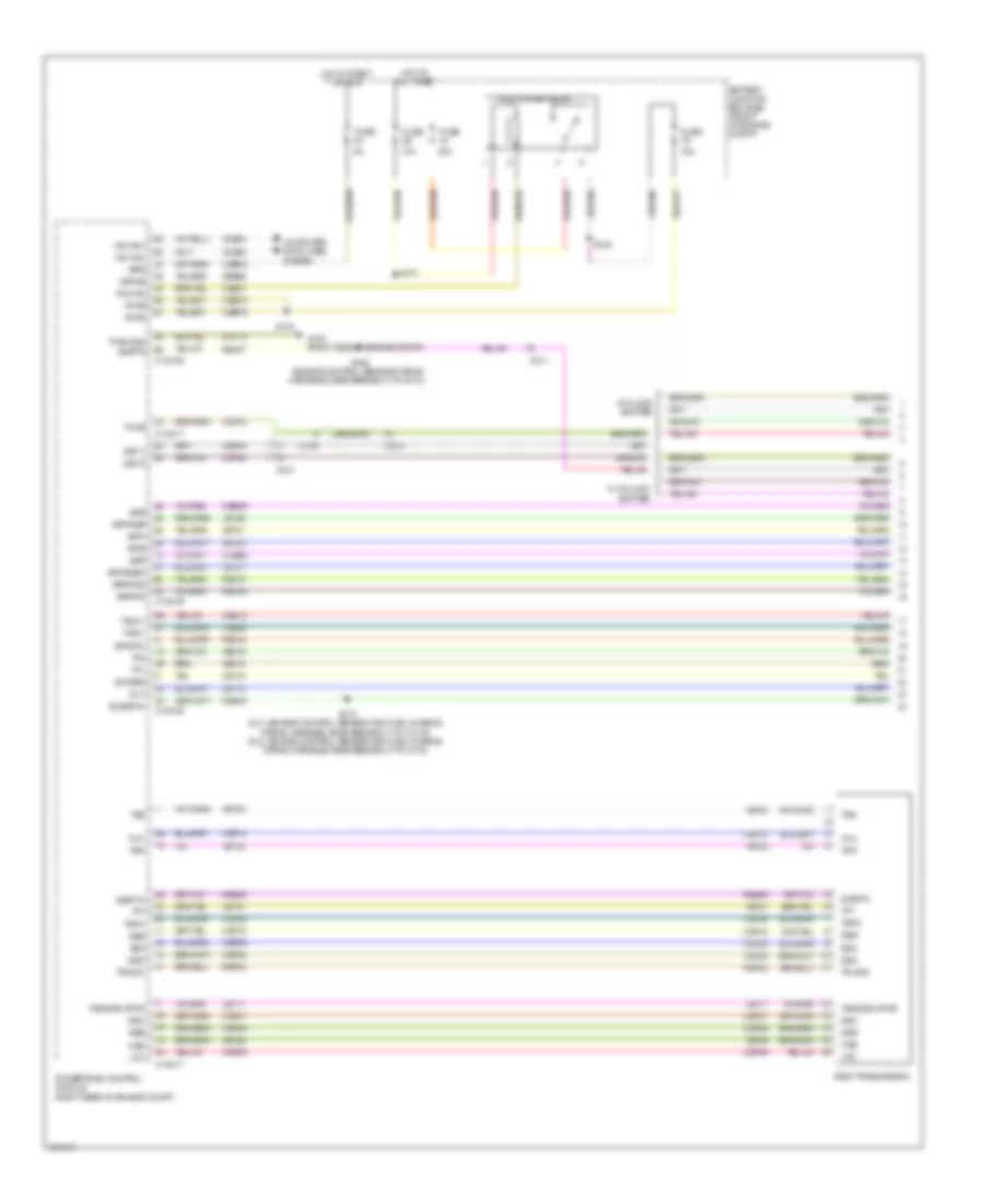
Cruise Control Wiring Diagram for Ford F-150 King Ranch 2013
List of elements for Cruise Control Wiring Diagram for Ford F-150 King Ranch 2013:
- (engine control sensor wiring harness, near breakout to c180) (3.5l) s104
- (left side of dash) g202
- (or vet26)
- 3.5l
- 3.7l
- 5.0l & 6.2l
- 6r80 transmission
- Accelerator pedal position (app) sensor (top of brake pedal assembly)
- App1
- App2
- Apprtn
- Apprtn2
- Appverf2
- Appvref
- Battery junction box (bjb) (front of engine compt)
- Body control module (bcm) (right kick panel)
- Bpp
- Bps
- Brake pedal position (bpp) switch (left side of dash)
- C1381b
- C1381e
- C1381t
- C1551b
- C1551e
- C175b
- C175e
- C175t
- C218b
- C218c
- C2280a
- C2414a
- C2414d
- Ccb08
- Ce412
- Ce426
- Ces09
- Clockspring (steering wheel)
- Cncl/ rsm
- Computer data lines system
- Electronic throttle control (etc) (6.2l: top rear of engine) (except 6.2l: top front of engine)
- Etcref
- Etcrtn
- Exterior lights system
- Fuse 10a
- Fuse 15a
- G100 (right side of engine compt)
- G102 (left front of engine compt)
- Gd113
- Gd133
- Hot at all times
- Hs can +
- Hs can -
- Hs can+
- Hs can-
- Instrument panel cluster (ipc)
- Interior lights system
- Le111
- Le134
- Le136
- Le137
- Left steering wheel switch
- Logic gnd
- Nca
- On/off
- Oss
- Powertrain control module (pcm) (right rear of engine compt)
- Pwr gnd
- Re134
- Re136
- Re137
- Re407
- Ret04
- S112 (engine control sensor wiring harness, near breakout to c110)
- S167 (engine control sensor wiring harness, near breakout to c110)
- Sbp23
- Sccrtn
- Sccs
- Set+
- Set-
- Shift interlock system
- Sigrtn
- Steering column control module (steering column)
- Tacm+
- Tacm-
- Tp1
- Tp2
- Tss/oss vpwr
- Vbatt
- Vdb04
- Vdb05
- Ve701
- Ve702
- Ve818
- Ve819
- W/ 5-button message center
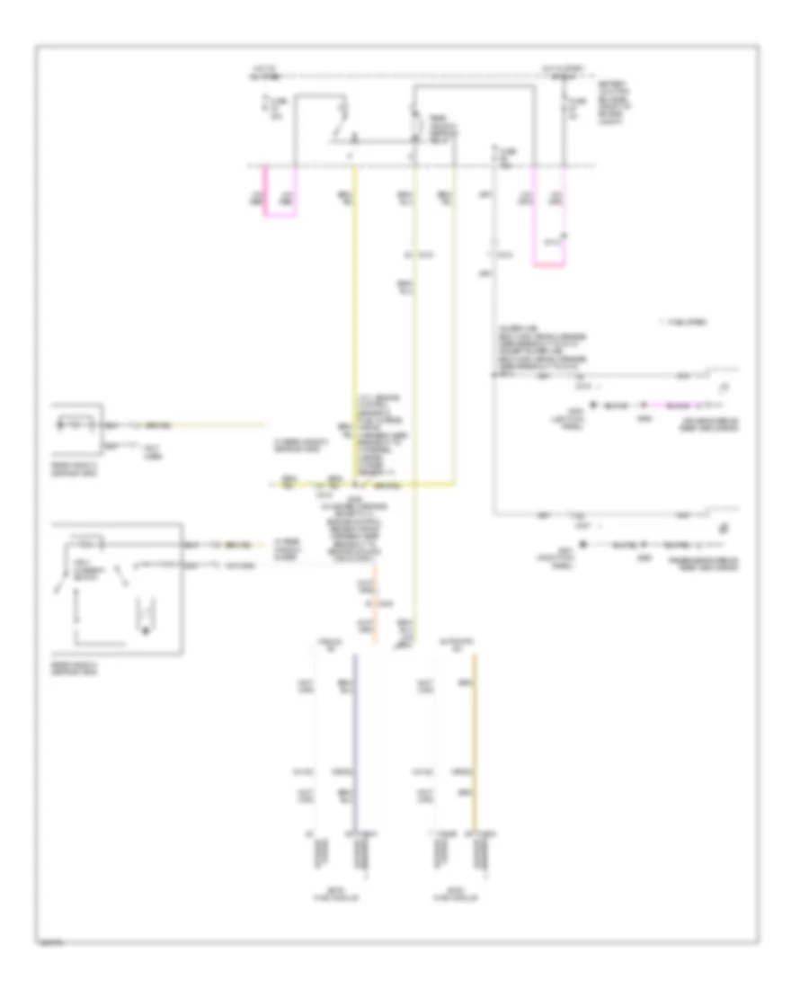
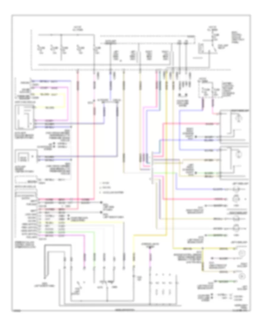
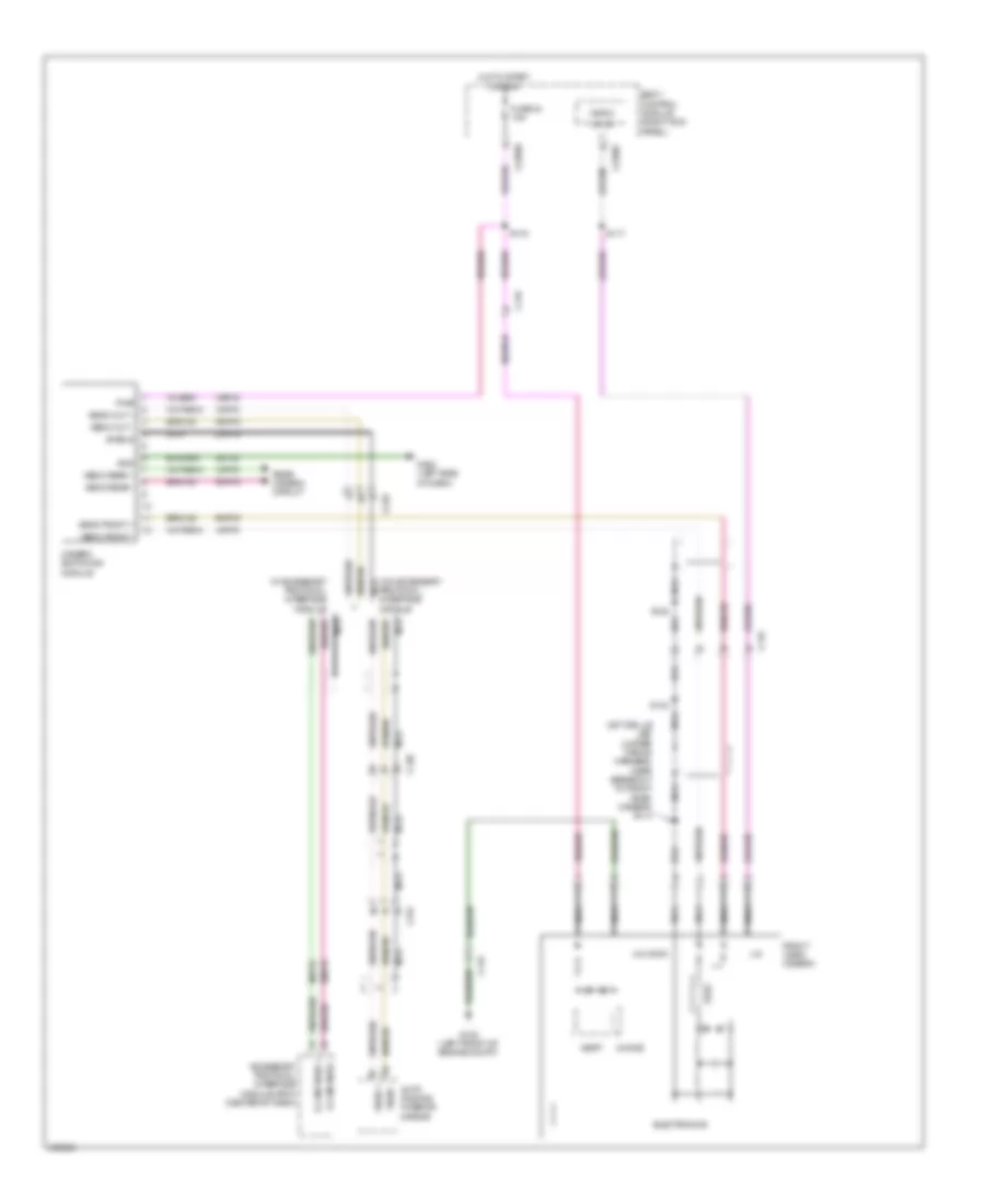
DEFOGGERS
Defoggers Wiring Diagram for Ford F-150 King Ranch 2013
List of elements for Defoggers Wiring Diagram for Ford F-150 King Ranch 2013:
- (3.7l: engine control sensor & fuel charge wiring harness, near breakout to universal heated oxygen sensor 11)
- (not used)
- (super cab: body main wiring harness, near breakout to c313) (except super cab: body main wiring harness, near breakout to c312) s313
- Automatic a/c
- Battery junction box (bjb) (front of engine compt)
- C210
- C212
- C215
- C219
- C228a
- C228b
- C237
- C238
- C294a
- Ch122
- Crd02
- Defrost request
- Defrost status
- Driver exterior rear view mirror
- Eatc hvac module
- Emtc hvac module
- Fuse 15a
- Fuse 40a
- Fuse 5a
- G200 (left kick panel)
- G201 (right kick panel)
- High current switch
- Hot at all times
- Hot in start or run
- If equipped
- Manual a/c
- Passenger exterior rear view mirror
- Rear window defrost grid
- Rear window defrost relay
- S118
- S160 (w/ heated mirrors) (except 3.7l: engine control sensor wiring harness, near breakout to engine cooling fan motor 1)
- S500
- S600
- W/ rear window defrost grid
- W/ rear window slider
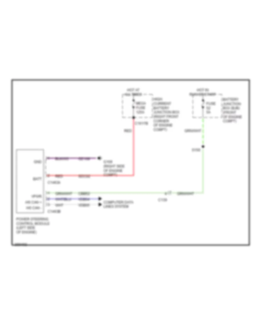
ELECTRONIC POWER STEERING
Electronic Power Steering Wiring Diagram for Ford F-150 King Ranch 2013
List of elements for Electronic Power Steering Wiring Diagram for Ford F-150 King Ranch 2013:
- Batt
- Battery junction box (bjb) (front of engine compt)
- C139
- C1463a
- C1463b
- C1617b
- Cbb52
- Computer data lines system
- Fuse 5a
- G109 (right side of engine compt)
- Gd108
- Gnd
- High current battery junction box (right front corner of engine compt)
- Hot at all times
- Hot in run or start
- Hs can +
- Hs can -
- Mega fuse 125a
- Power steering control module (left side of engine)
- Red
- S156
- Sdc02
- Vdb04
- Vdb05
- Vpwr
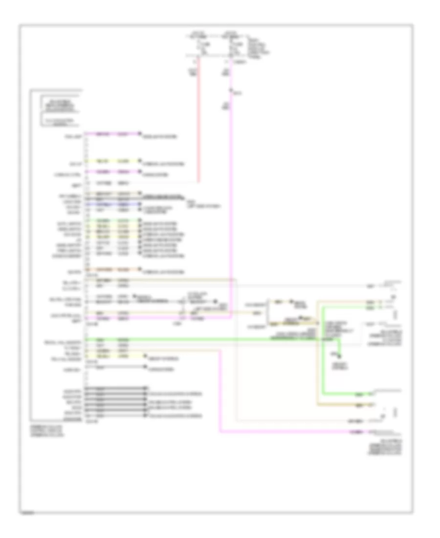
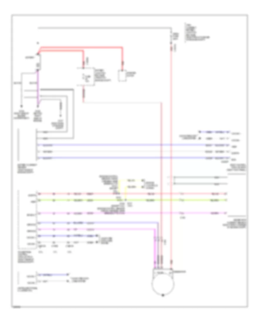
Power Steering Column Wiring Diagram for Ford F-150 King Ranch 2013
List of elements for Power Steering Column Wiring Diagram for Ford F-150 King Ranch 2013:
- (main wiring harness, near breakout to c2600) s292
- Adj pdl mtr (fwd)
- Adjustable pedal/steering column switch
- Adjustable steering column telescope motor (steering column)
- Adjustable steering column tilt motor (steering column)
- Audio pwr
- Audio rtn
- Auto lamp on
- Body control module (right kick panel)
- C2280a
- C2414a
- C2414b
- C2414c
- C2414d
- C264
- Clf19
- Clf21
- Clf23
- Clf24
- Cln55
- Cln56
- Cls34
- Com mtr pdl/col
- Computer data lines system
- Cpp01
- Cpp02
- Cpp04
- Cpp22
- Crh04
- Cruise control system
- Crw15
- Dim down
- Dim rtn
- Dim up
- Dome on/defeat
- Fog lamp
- Frt wiper hi
- Fuse 15a
- G202 (left side of dash)
- G203 (left side of dash)
- Gd133
- Gd138
- Headlamp off
- Headlamp on
- Headlights system
- Horn rly ctrl
- Horn sw -
- Horns system
- Hot at all times
- Hs can +
- Hs can -
- Interior lights system
- Lin
- Logic gnd
- Lpp06
- Memory systems
- Multi-function switch
- Nca
- Park lamp on
- Pd/col hall sns rtn
- Pdl hall sns sig
- Pwr gnd
- Rln29
- Rpp06
- S212
- S293 (main wiring harness, near breakout to c2600)
- Sbp23
- Sbp24
- Scc rtn
- Sccs
- Seats & memory systems
- Seats system
- Sound & navigation systems
- Steering column control module (steering column)
- Sync pwr
- Sync rtn
- Tel mtr +/-
- Tel sns +
- Tilt mtr +/-
- Tilt sns +
- Vbatt
- Vdb04
- Vdb05
- Vdn05
- Vln36
- Vpp08
- Vpp17
- W/ column shifter
- W/ memory
- W/o memory
- Wiper/washer system
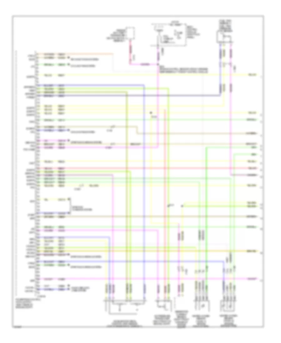
ENGINE PERFORMANCE
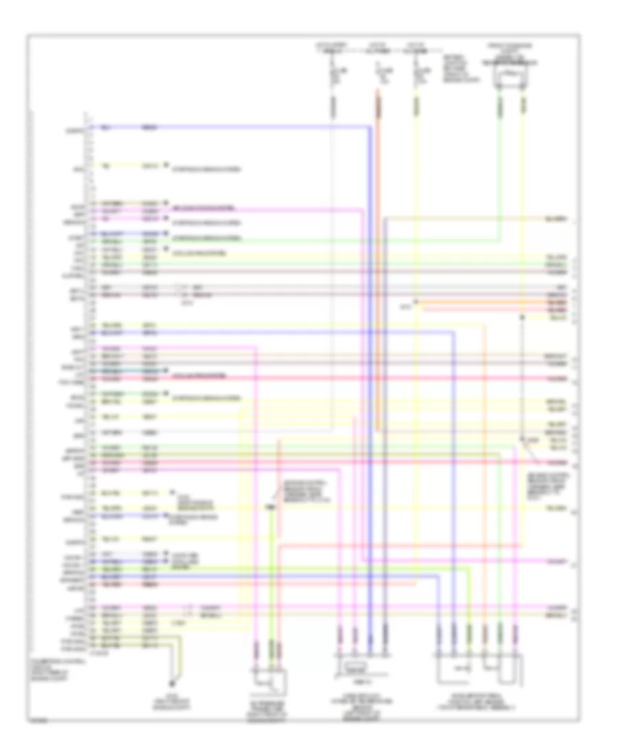
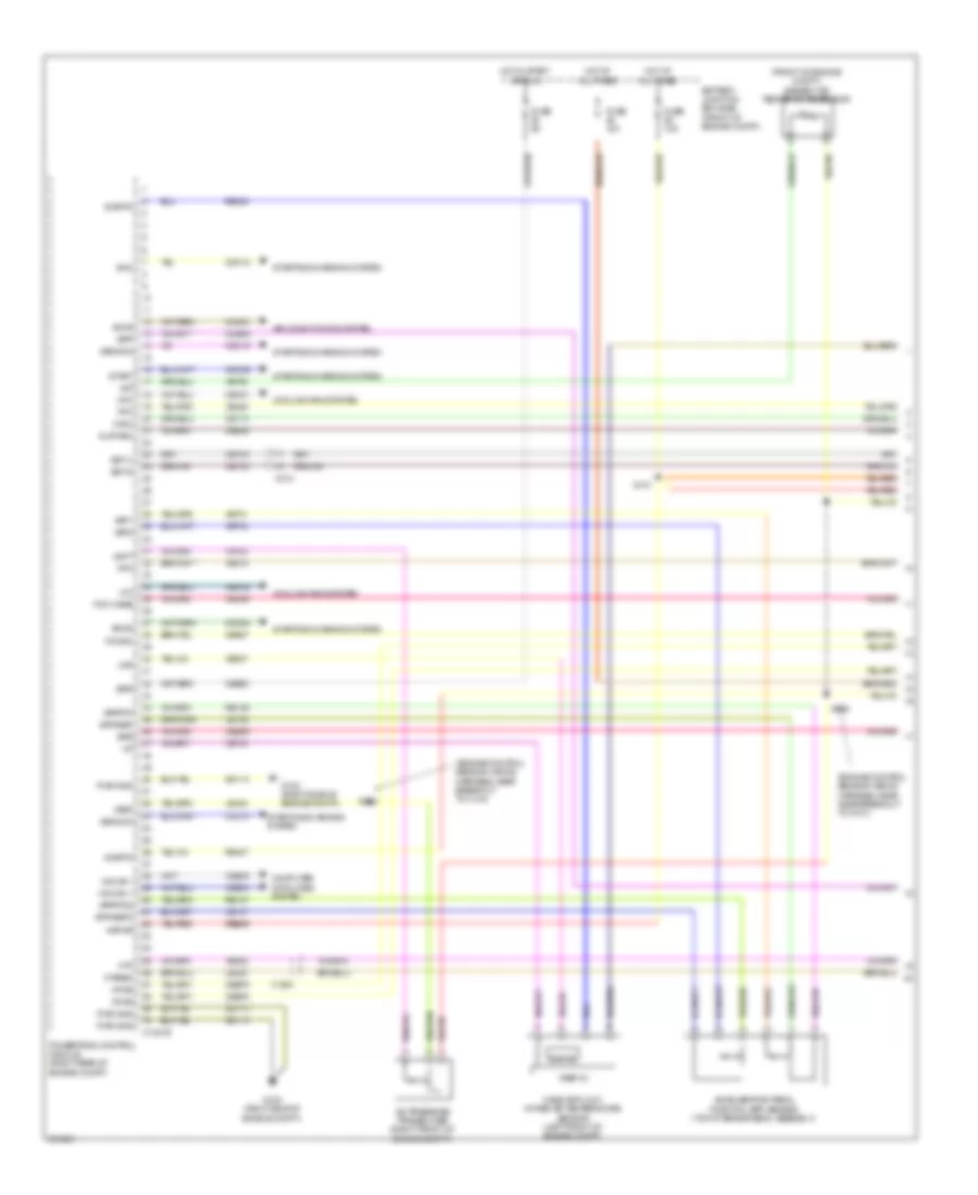
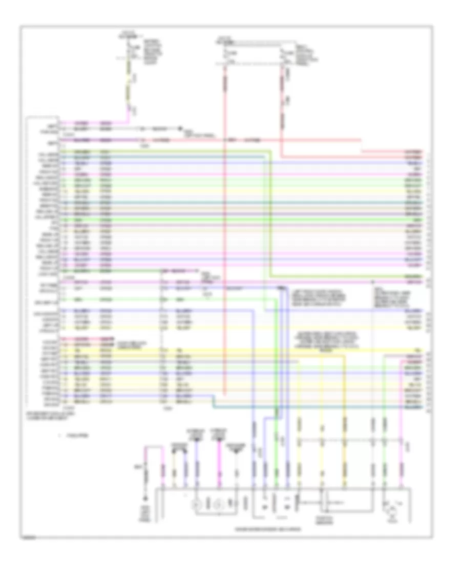
3.5L TWIN TURBO
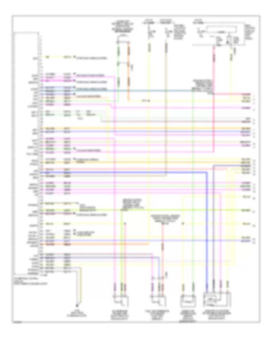
3.5L Twin Turbo, Engine Performance Wiring Diagram (1 of 6) for Ford F-150 King Ranch 2013
List of elements for 3.5L Twin Turbo, Engine Performance Wiring Diagram (1 of 6) for Ford F-150 King Ranch 2013:
- (fuel tank assembly) fuel tank pressure (ftp) sensor
- A/c pressure transducer (right front of engine compt)
- Aat
- Accelerator pedal position (app) sensor (top of brake pedal assembly)
- Accr
- Acpt
- Air conditioning system
- App1
- App2
- Apprtn
- Apprtn2
- Appvref
- Appvref2
- Body control module (right kick panel)
- Bpp
- C146
- C1551b
- C1581
- C192
- C214
- C2280f
- Cact
- Canv
- Cbb53
- Ccb08
- Cdc10
- Cdc12
- Cdc15
- Cdc35
- Cdc54
- Ce113
- Ce114
- Ce233
- Ce234
- Ce436
- Ce607
- Cec01
- Cec02
- Ch302
- Computer data lines system
- Cooling fans system
- Evapcp
- Fpc
- Fpm
- Ftpref
- Fuse 10a
- Gencom
- Generator current sensor (right front corner of engine compt)
- Genmon
- Heated oxygen sensor (ho2s) 12 (engine exhaust pipe)
- Heated oxygen sensor (ho2s) 22 (engine exhaust pipe)
- Hfc
- Ho2s12
- Ho2s22
- Hot at all times
- Hs can +
- Hs can -
- Htr12
- Htr22
- Ispr
- Le136
- Le137
- Le230
- Le424
- Lfc
- Micro
- Passive anti-theft transceiver (ignition switch assembly)
- Pcm wake
- Pcm wake up (fet)
- Pcmrc
- Powertrain control module (pcm) (right rear of engine compt)
- Re136
- Re137
- Re145
- Re332
- Re405
- Re407
- S140
- S141
- S240 (engine control sensor wiring harness, near breakout to body control module)
- Sigrtn
- Smc
- Smcs
- Start
- Starting/ charging system
- Starting/charging system
- Vdb04
- Vdb05
- Ve225
- Ve518
- Ve701
- Ve702
- Ve731
- Ve733
- Ve750
- Vh433
- Vref
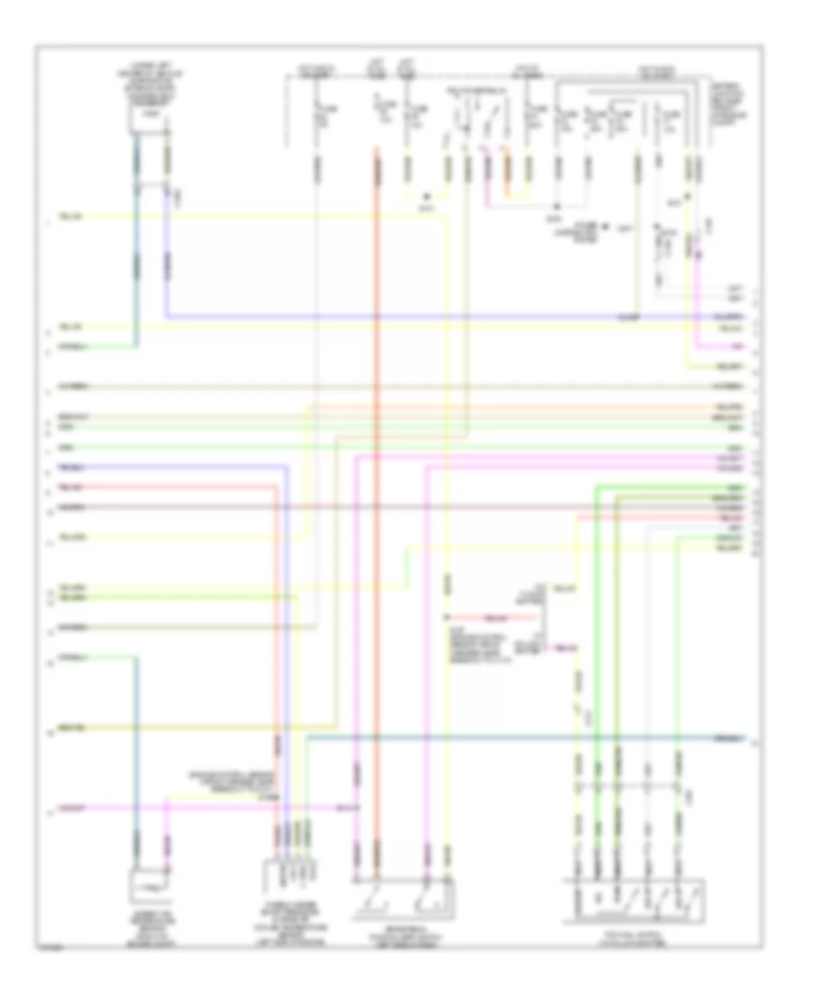
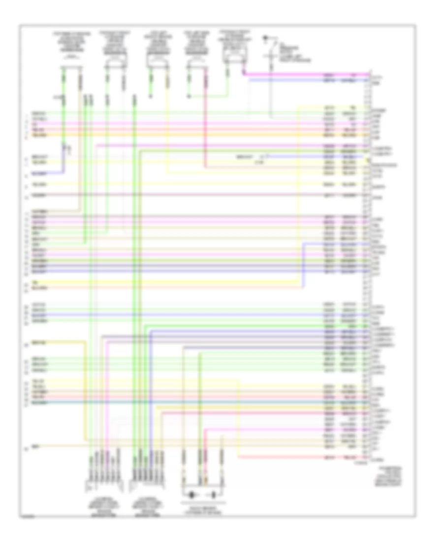
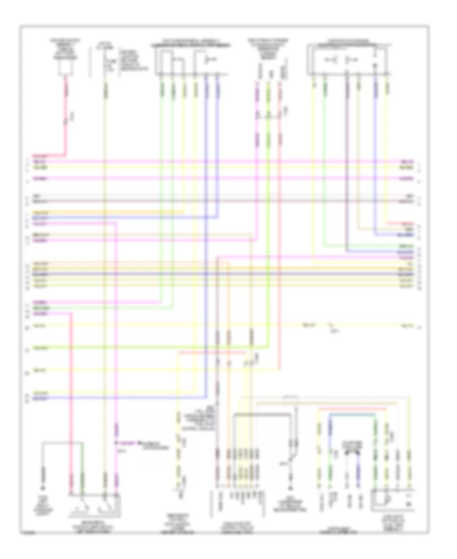
3.5L Twin Turbo, Engine Performance Wiring Diagram (2 of 6) for Ford F-150 King Ranch 2013
List of elements for 3.5L Twin Turbo, Engine Performance Wiring Diagram (2 of 6) for Ford F-150 King Ranch 2013:
- (engine control sensor wiring harness, near breakout to g101) s169
- (under left center of vehicle) evaporative emission (evap) canister vent solenoid
- 10a
- 50a
- Ambient air temperature sensor (front of engine compt)
- Battery junction box (bjb) (front of engine compt)
- Brake pedal position (bpp) switch (left side of dash)
- C-vref
- C146
- C1581
- C211
- C264
- Cact
- Fuse
- Fuse 10a
- Fuse 15a
- Fuse 20a
- Fuse 25a
- Fuse 5a
- Hot at all times
- Hot in run or start
- Nca
- Pcm power relay
- Power distribution system
- R/s
- S101
- S105
- S112
- S121
- S125
- S129
- S167 (engine control sensor wiring harness, near breakout to c110)
- Sigrtn
- Sst-d
- Sst-u
- Tcbp
- Tow haul switch (w/ column shifter)
- Tows
- Turbocharger boost pressure/ charge air cooler temperature sensor (left side of engine)
- W/ column shifter
- W/ floor shifter
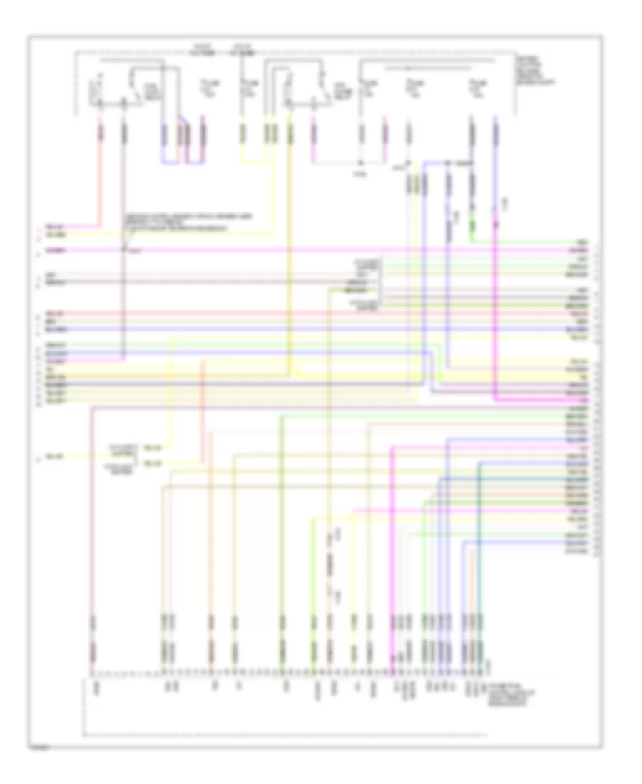
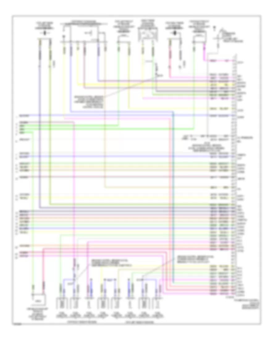
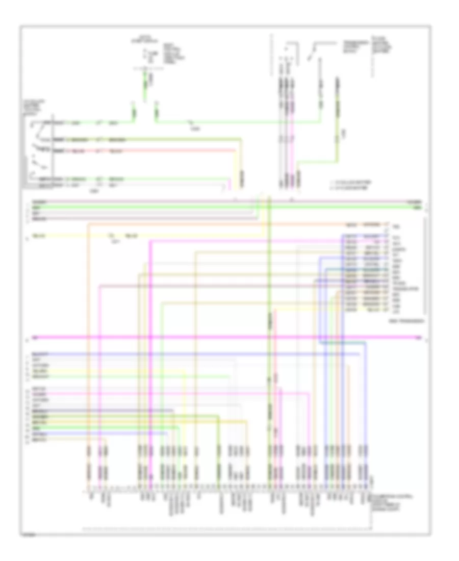
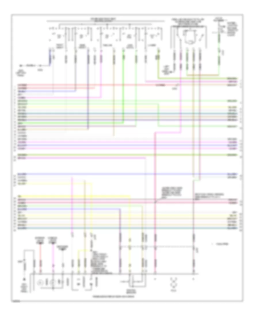
3.5L Twin Turbo, Engine Performance Wiring Diagram (3 of 6) for Ford F-150 King Ranch 2013
List of elements for 3.5L Twin Turbo, Engine Performance Wiring Diagram (3 of 6) for Ford F-150 King Ranch 2013:
- (w/ floor shifter) floor shifter
- Bcs2 alt
- Body control module (right kick panel)
- Bps
- C-vref
- C1551b
- C1551e
- C210
- C211
- C213
- C214
- C2280b
- C2280f
- C329
- Cbb75
- Ccb08
- Ce205
- Ce206
- Ce207
- Ce208
- Ce209
- Ce210
- Ce226
- Ce305
- Ce308
- Ce412
- Ce426
- Ces09
- Cet07
- Cet25
- Cet34
- Cet42
- Cet43
- Cop3e
- Cop6f
- Ftp
- Fuel pump (fet)
- Fuse 5a
- Fvr
- Fvrrtn
- G100 (right side of engine compt)
- Gd113
- Hot in start or run
- Iat
- Iat1
- Inj1
- Inj1rtn
- Inj2
- Inj2rtn
- Inj3
- Inj3rtn
- Inj4
- Inj4rtn
- Inj5
- Inj5rtn
- Inj6
- Inj6rtn
- Micro
- Nca
- Powertrain control module (pcm) (right rear of engine compt)
- Pwrgnd
- Re150
- Re205
- Re206
- Re207
- Re208
- Re209
- Re210
- Re226
- Re804
- S103
- Sigrtn
- Ssc
- Sst d
- Sst u
- Sst-d
- Sst-u
- Starting/ charging system
- Tacm+
- Tacm-
- Tcbp
- Tcip
- Ticp
- Tows
- Transmission control switch
- Tspc
- Turbocharger intake pressure & temperature (tcipt) sensor
- Vdc61
- Ve804
- Ve922
- Vpwr
- W/ column shifter
- W/ floor shifter
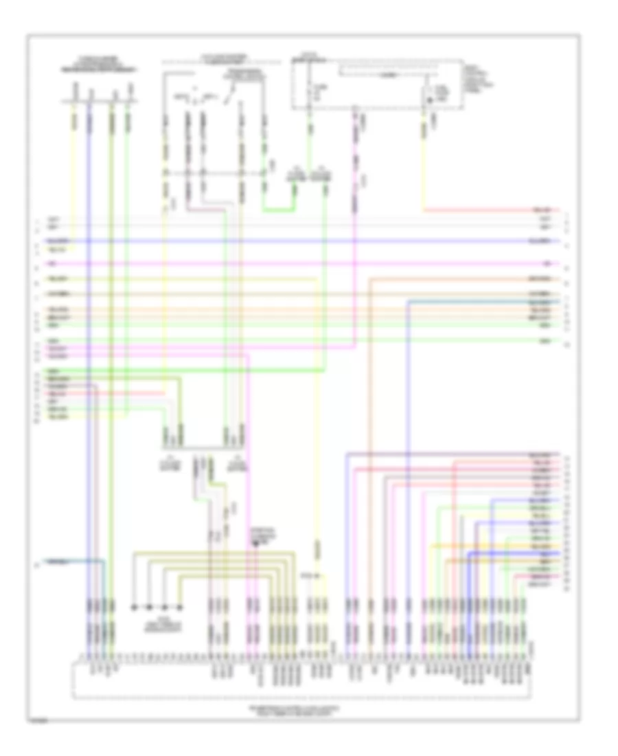
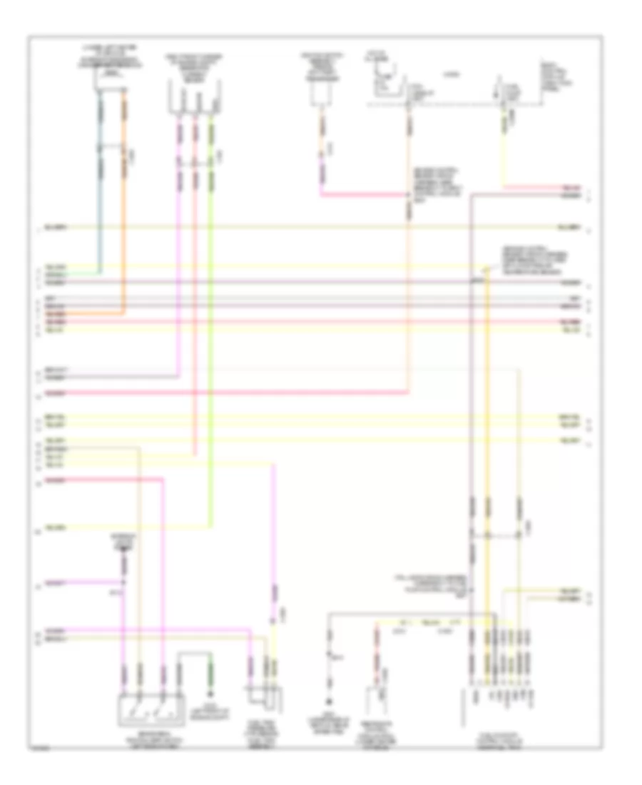
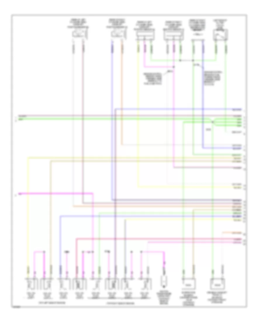
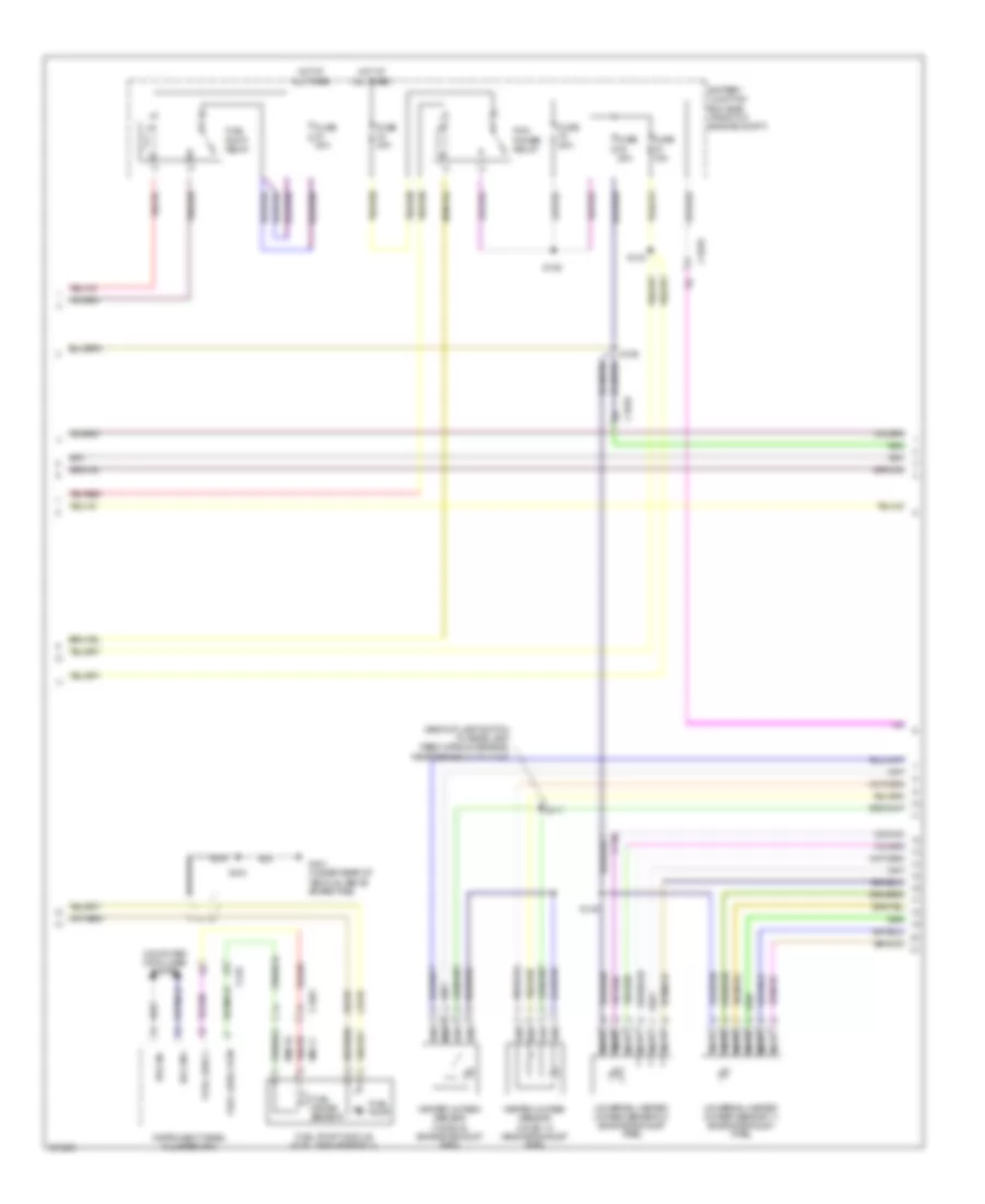
3.5L Twin Turbo, Engine Performance Wiring Diagram (4 of 6) for Ford F-150 King Ranch 2013
List of elements for 3.5L Twin Turbo, Engine Performance Wiring Diagram (4 of 6) for Ford F-150 King Ranch 2013:
- (rear of right cylinder head) cylinder head temperature (cht) sensor
- (top left side of engine)
- (top right side of engine)
- (under rear of vehicle, above spare tire) g401
- 6r80 transmission
- Battery junction box (bjb) (front of engine compt)
- C1581
- C1586
- C1587
- C210
- C310a
- Ce515
- Ce608
- Cet05
- Cet06
- Cet07
- Cet08
- Cet09
- Cet10
- Cet16
- Cet25
- Computer data lines system
- Cr167
- Ens
- Fp pwr
- Fp rtn
- Fpc
- Fpm
- Fuel injection pump (top left rear of engine)
- Fuel injector
- Fuel lvl1
- Fuel pump (fp) control module (near fuel tank)
- Fuel pump module (fuel tank assembly)
- Fuel pump relay
- Fuse 20a
- Gd117
- Gnd
- Hot at all times
- Hs can +
- Hs can -
- In breakout to fuel pump control module)
- Instrument panel cluster (ipc)
- Le111
- Lpc
- Nca
- Oss
- Re405
- Re515
- Restraints control module (rcm) (under center console)
- Ret04
- Ret24
- Ret33
- Rmc32
- Rtn
- S107 (engine control sensor wiring harness, near breakout to mass air flow/intake air temperature sensor)
- S410
- Sigrtn
- Ssa
- Ssb
- Ssc
- Ssd
- Sse
- Tcc
- Tft
- Tr gnd
- Trp
- Tspc
- Tss
- Tss/oss vpwr
- Ve225
- Ve518
- Vet27
- Vet32
- Vmc11
- Vpwr
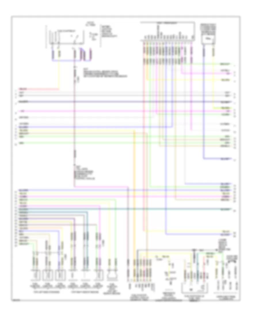
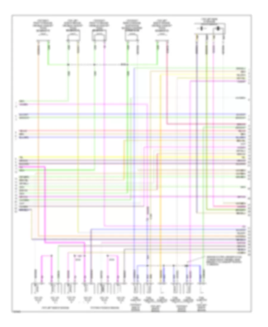
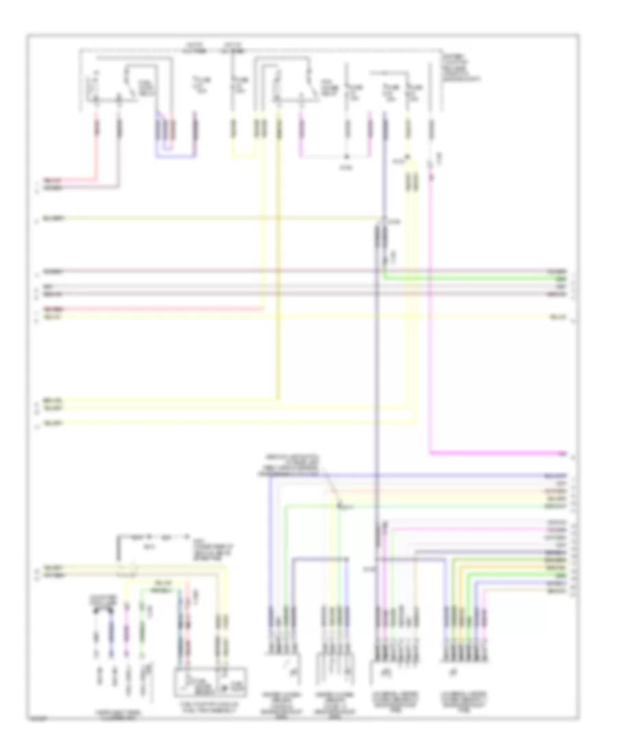
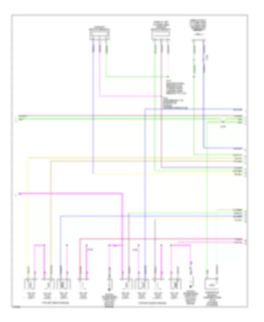
3.5L Twin Turbo, Engine Performance Wiring Diagram (5 of 6) for Ford F-150 King Ranch 2013
List of elements for 3.5L Twin Turbo, Engine Performance Wiring Diagram (5 of 6) for Ford F-150 King Ranch 2013:
- (engine control sensor & fuel charge wiring harness, near breakout to c1587) s166
- (engine control sensor & fuel charge wiring harness, near breakout to fuel rail pressure sensor)
- (engine control sensor and fuel charge wiring harness, near breakout to powertrain control module)
- (engine control sensor wiring harness, near breakout to c180)
- (left front of engine compt) electronic compressor bypass valve
- (rear of left cylinder head) camshaft position (cmp21) sensor 21
- (rear of right cylinder head) camshaft position (cmp11) sensor 11
- (top front of engine) turbo- charger (tc) wastegate regulating valve solenoid
- (top left side of engine)
- (top rear of engine) fuel rail pressure (frp) sensor
- (top rear of engine) manifold absolute pressure/intake air temperature (map/iat2) sensor 2
- (top right side of engine)
- C136
- Camshaft position 12 (cmp12) sensor (rear of right cylinder head)
- Camshaft position 22 (cmp22) sensor (rear of left cylinder head)
- Coil on plug (cop) 1
- Coil on plug (cop) 2
- Coil on plug (cop) 3
- Coil on plug (cop) 4
- Coil on plug (cop) 5
- Coil on plug (cop) 6
- Crankshaft position (ckp) sensor
- E-vref
- Electronic throttle control (top front of engine)
- G104 (rear of right cylinder head)
- G105 (left side of engine)
- Iat2
- S104
- S113
- S128
- S139
- S164
- S165
- S173
- S174
- Sigrtn
- Tmap
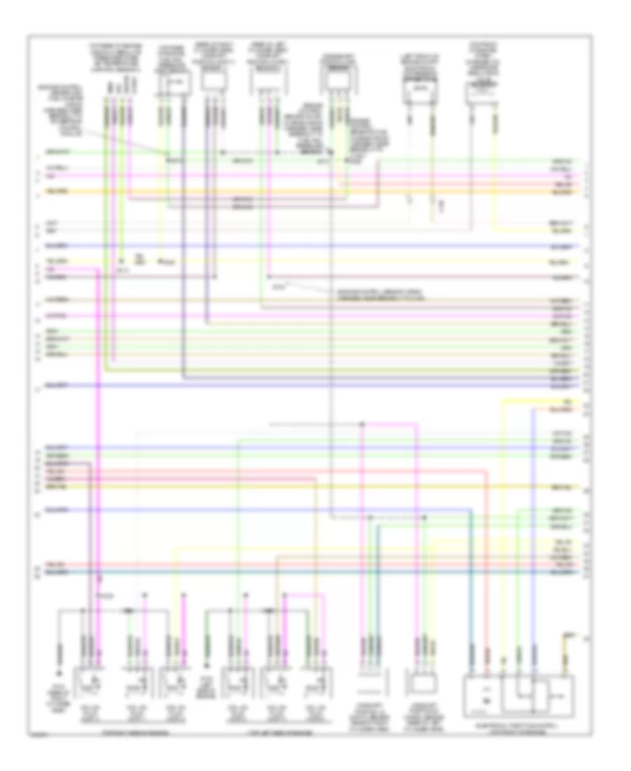
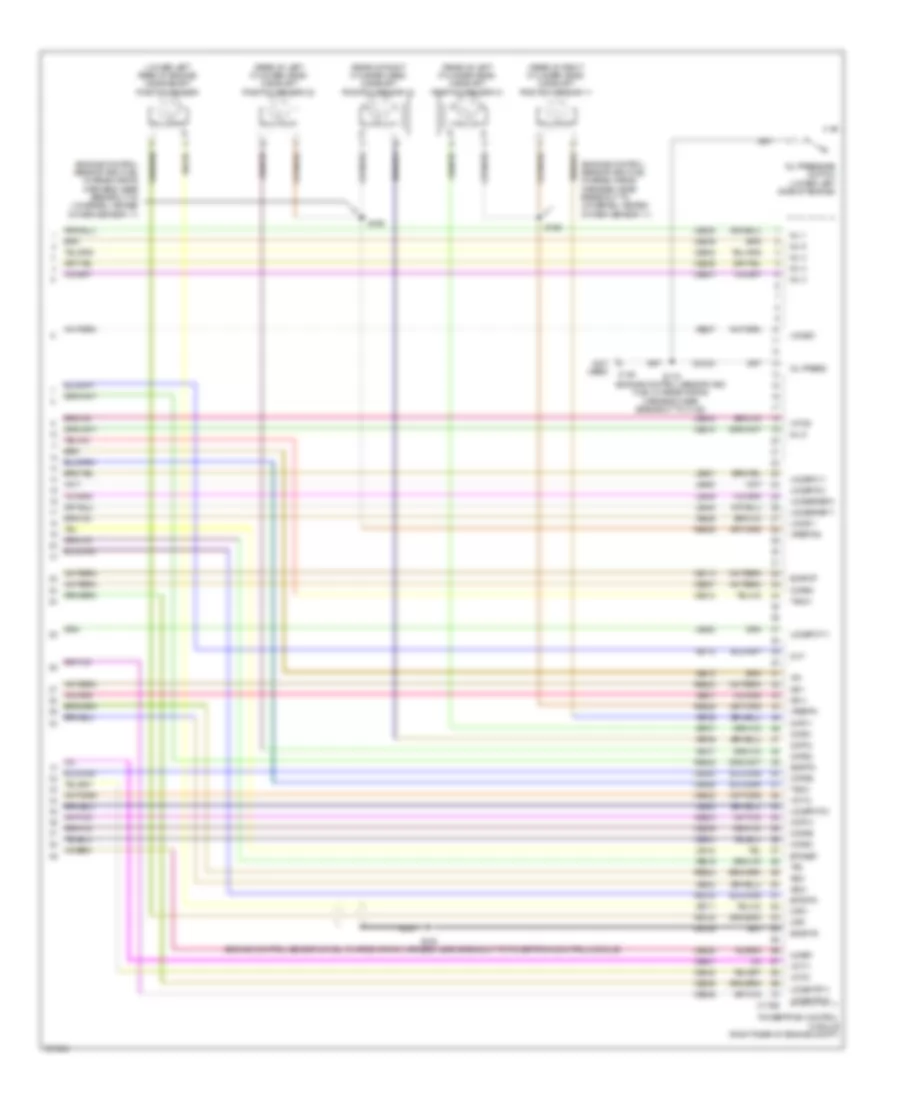
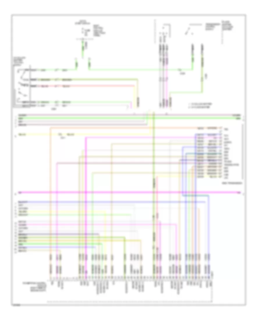
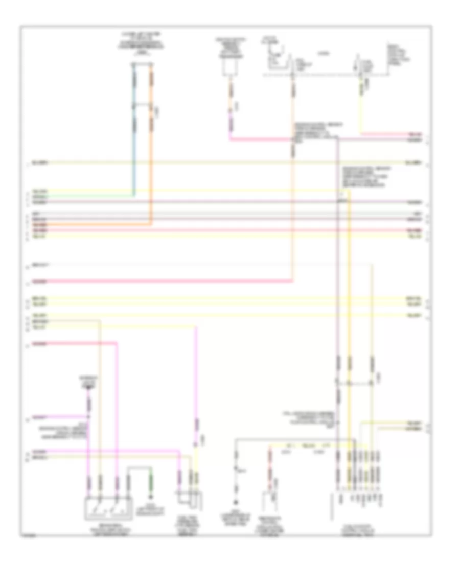
3.5L Twin Turbo, Engine Performance Wiring Diagram (6 of 6) for Ford F-150 King Ranch 2013
List of elements for 3.5L Twin Turbo, Engine Performance Wiring Diagram (6 of 6) for Ford F-150 King Ranch 2013:
- (top left side of engine) variable camshaft timing (vct21) solenoid 21
- (top left side of engine) variable camshaft timing (vct22) solenoid 22
- (top rear of engine) evaporative emission (evap) canister purge valve
- (top right front of engine) variable camshaft timing (vct11) solenoid 11
- (top right front of engine) variable camshaft timing (vct12) solenoid 12
- C146
- C1551e
- Ce235
- Ce236
- Ce303
- Ce304
- Ce306
- Ce307
- Ce421
- Ce422
- Ce442
- Ce443
- Cet05
- Cet06
- Cet08
- Cet09
- Cet10
- Cet16
- Cht
- Ckp
- Cmc24
- Cmp11
- Cmp12
- Cmp21
- Cmp22
- Cop1a
- Cop2c
- Cop4b
- Cop5d
- Cr167
- Ecbv/tcwrvs
- Etcref
- Etcrtn
- Frp
- Iat2
- Knock sensor (top rear of engine)
- Ks1 +
- Ks1 -
- Ks2 +
- Ks2 -
- Le111
- Le134
- Le143
- Le144
- Le423
- Le448
- Le449
- Le450
- Le451
- Le452
- Le453
- Lpc
- Map
- Nca
- Oil pressure switch (lower left front of engine)
- Ops
- Oss
- Powertrain control module (pcm) (right rear of engine compt)
- Re134
- Re323
- Re324
- Re405
- Re454
- Ret04
- Ret24
- Ret33
- Sigrtn
- Ssa
- Ssb
- Ssd
- Sse
- Tan
- Tcc
- Tft
- Tp 1
- Tp 2
- Tr gnd
- Trp
- Tss
- Universal heated oxygen sensor (ho2s) 11 (engine exhaust pipe)
- Universal heated oxygen sensor (ho2s) 21 (engine exhaust pipe)
- Uo2s11
- Uo2s21
- Uo2sgref11
- Uo2sgref21
- Uo2shtr11
- Uo2shtr21
- Uo2spc11
- Uo2spc21
- Uo2spct21
- Uo2ssptc11
- Vct11
- Vct12
- Vct21
- Vct22
- Ve706
- Ve707
- Ve711
- Ve712
- Ve727
- Ve740
- Ve801
- Ve802
- Ve804
- Ve818
- Ve819
- Ve824
- Ve826
- Ve827
- Vet27
- Vet32
- Vpwr
- Vref
3.7L FLEX FUEL
3.7L Flex Fuel, Engine Performance Wiring Diagram (1 of 6) for Ford F-150 King Ranch 2013
List of elements for 3.7L Flex Fuel, Engine Performance Wiring Diagram (1 of 6) for Ford F-150 King Ranch 2013:
- (engine control sensor wiring harness, near breakout to body control module) s240
- (engine control sensor wiring harness, near breakout to c144) s162
- (engine control sensor wiring harness, near breakout to g101) s169
- (under left center of vehicle) evaporative emission canister vent solenoid
- A/c pressure transducer (right front of engine compt)
- Aat
- Accr
- Acpt
- Air conditioning system
- Ambient air temperature sensor (front of engine compt)
- App1
- App2
- Apprtn
- Apprtn2
- Appvref
- Appvref2
- Battery junction box (bjb) (front of engine compt)
- Bcs2 alt
- Body control module (right kick panel)
- Bpp
- Bps
- C1581
- C175b
- C210
- C2280f
- Canv
- Cbb53
- Cbb75
- Ccb08
- Cdc10
- Cdc12
- Cdc15
- Cdc35
- Cdc54
- Ce114
- Ce436
- Ce607
- Ce608
- Cec01
- Cec02
- Ces09
- Cet42
- Cet43
- Ch302
- Computer data lines system
- Cooling fans system
- Digital
- Fpc
- Fpm
- Ftp
- Ftpref
- Fuel pump (fet)
- Fuel tank pressure (ftp) sensor (fuel tank assembly)
- Fuse 10a
- Fuse 5a
- G100 (right side of engine compt)
- Gd113
- Gencom
- Genmon
- Hfc
- Hot at all times
- Hot in run or start
- Hs can +
- Hs can -
- Iat
- Injpwrm
- Ispr
- Kapwr
- Le136
- Le137
- Le230
- Le424
- Lfc
- Maf
- Mass air flow/intake air temperature sensor (left front of engine compt)
- Micro
- Pcm wake
- Pcm wake up (fet)
- Pcmrc
- Powertrain control module (right rear of engine compt)
- Pwrgnd
- Re136
- Re137
- Re320
- Re407
- S101
- Sbb26
- Sigrtn
- Smc
- Smcs
- Sst d
- Sst u
- Start
- Starting/charging system
- Vdb04
- Vdb05
- Vdc61
- Ve225
- Ve518
- Ve701
- Ve702
- Ve740
- Ve750
- Ve807
- Ve922
- Vh433
- Vpwr
- Vref
3.7L Flex Fuel, Engine Performance Wiring Diagram (2 of 6) for Ford F-150 King Ranch 2013
List of elements for 3.7L Flex Fuel, Engine Performance Wiring Diagram (2 of 6) for Ford F-150 King Ranch 2013:
- (ignition switch assembly) passive anti-theft transceiver
- (right front corner of engine compt) generator current sensor
- (top front of engine) electronic throttle control
- (top of brake pedal assembly) accelerator pedal position (app) sensor
- 1 rtn
- Battery junction box (bjb) (front of engine compt)
- Bcs2 alt
- Brake pedal position (bpp) switch (left side of dash)
- C1581
- C192
- C210
- C211
- C214
- C310a
- Ce515
- Ce608
- Computer data lines system
- Cr167
- Ens
- Exterior lights system
- Fp pwr
- Fp rtn
- Fpc
- Fpm
- Fuel lvl
- Fuel lvl 1
- Fuel pump (fp) control module (near fuel tank)
- Fuel pump (fp) module (fuel tank assembly)
- Fuse 10a
- G102 (left front of engine compt)
- G401 (under rear of vehicle, above spare tire)
- Gd117
- Gnd
- Hot at all times
- Hs can +
- Hs can -
- Instrument panel cluster (ipc)
- Nca
- Re515
- Restraints control module (rcm) (under center console)
- Rmc32
- S112
- S407 (tail lamps wiring harness, in breakout to fuel pump control module)
- S410
- Sigrtn
- Ve225
- Ve518
- Vmc11
- Vpwr fuel
- Vref
3.7L Flex Fuel, Engine Performance Wiring Diagram (3 of 6) for Ford F-150 King Ranch 2013
List of elements for 3.7L Flex Fuel, Engine Performance Wiring Diagram (3 of 6) for Ford F-150 King Ranch 2013:
- (engine control sensor wiring harness, near breakout to mass air flow/intake air temperature sensor)
- Battery junction box (bjb) (front of engine compt)
- C140
- C146
- C175t
- C214
- Ce233
- Ce234
- Cet05
- Cet06
- Cet07
- Cet08
- Cet09
- Cet10
- Cet18
- Cet25
- Cet34
- Fuel pump relay
- Fuse 15a
- Fuse 20a
- Fuse 40a
- Ho2s12
- Ho2s22
- Hot at all times
- Htr12
- Htr22
- Le111
- Lpc
- Oss
- Pcm power relay
- Powertrain control module (right rear of engine compt)
- Re405
- Ret24
- S103
- S107
- S125
- S129
- Sigrtn
- Ssa
- Ssb
- Ssc
- Ssd
- Sse
- Tcc
- Tft
- Tows
- Tr p
- Trgnd
- Tspc
- Tss
- Ve731
- Ve733
- Vet26
- Vet27
- Vet32
- Vet33
- Vpwr
- W/ column shifter
- W/ floor shifter
3.7L Flex Fuel, Engine Performance Wiring Diagram (4 of 6) for Ford F-150 King Ranch 2013
List of elements for 3.7L Flex Fuel, Engine Performance Wiring Diagram (4 of 6) for Ford F-150 King Ranch 2013:
- (rear of right cylinder head) cylinder head temperature sensor
- (w/ column shifter)
- (w/ floor shifter) floor shifter
- 6r80 transmission
- Body control module (right kick panel)
- C1026
- C2280b
- C264
- C329
- Cet05
- Cet06
- Cet07
- Cet08
- Cet09
- Cet10
- Cet18
- Cet25
- Fuse 5a
- Heated oxygen sensor (ho2s) 12
- Heated oxygen sensor (ho2s) 22
- Hot in start or run
- Le111
- Lpc
- Nca
- Oss
- R/s
- Re405
- Ret24
- S111 (backup lamp switch to rear lamp feed wiring harness, near breakout to c140)
- S148
- Sigrtn
- Ssa
- Ssb
- Ssc
- Ssd
- Sse
- Sst d
- Sst u
- Sst-d
- Sst-u
- Tcc
- Tft
- Tow haul switch
- Tows
- Tr gnd
- Tr p
- Transmission control switch
- Tspc
- Tss
- Tss/oss vpwr
- Universal heated oxygen sensor 11 (engine exhaust pipe)
- Universal heated oxygen sensor 21 (engine exhaust pipe)
- Vet26
- Vet27
- Vet32
- Vet33
- W/ column shifter
- W/ floor shifter
3.7L Flex Fuel, Engine Performance Wiring Diagram (5 of 6) for Ford F-150 King Ranch 2013
List of elements for 3.7L Flex Fuel, Engine Performance Wiring Diagram (5 of 6) for Ford F-150 King Ranch 2013:
- (engine control sensor & fuel charge wiring harness, near breakout to camshaft position 21 sensor)
- (top left rear of engine) knock sensor
- (top left side of engine)
- (top left side of engine) variable camshaft timing solenoid 21
- (top left side of engine) variable camshaft timing solenoid 22
- (top right front of engine) variable camshaft timing solenoid 11
- (top right front of engine) variable camshaft timing solenoid 12
- (top right rear of engine) evaporative emission canister purge valve
- (top right side of engine)
- C146
- Coil on plug
- Fuel injector
- Fuel injector (top left side of engine)
- Fuel injector (top right side of engine)
- S135
- S136
- S137
- S139
- Tan
3.7L Flex Fuel, Engine Performance Wiring Diagram (6 of 6) for Ford F-150 King Ranch 2013
List of elements for 3.7L Flex Fuel, Engine Performance Wiring Diagram (6 of 6) for Ford F-150 King Ranch 2013:
- (engine control sensor & fuel charge wiring harness, near breakout to powertrain control module)
- (engine control sensor and fuel charge wiring harness, near breakout to universal heated oxygen sensor 11)
- (lower left rear of engine) crankshaft position sensor
- (not used)
- (rear of left cylinder head) camshaft position sensor 21
- (rear of left cylinder head) camshaft position sensor 22
- (rear of right cylinder head) camshaft position sensor 11
- (rear of right cylinder head) camshaft position sensor 12
- C146
- C175e
- Ce113
- Ce205
- Ce206
- Ce207
- Ce208
- Ce209
- Ce210
- Ce235
- Ce236
- Ce303
- Ce304
- Ce305
- Ce306
- Ce307
- Ce308
- Ce412
- Ce421
- Ce422
- Ce426
- Ce442
- Ce443
- Cht
- Ckp+
- Ckp-
- Cmc24
- Cmp11
- Cmp12
- Cmp21
- Cmp22
- Cop1a
- Cop2c
- Cop3e
- Cop4b
- Cop5d
- Cop6f
- De135
- Etcref
- Etcrtn
- Evapcp
- Inj 1
- Inj 2
- Inj 3
- Inj 4
- Inj 5
- Inj 6
- Ks1+
- Ks1-
- Ks2+
- Ks2-
- Le134
- Le448
- Le449
- Le450
- Le451
- Le452
- Le453
- Nca
- Oil press
- Oil pressure switch (lower left side of engine)
- Powertrain control module (right rear of engine compt)
- Re134
- Re135
- Re323
- Re324
- Re405
- Re429
- S116 (engine control sensor and fuel charge wiring harness, near breakout to c146)
- S138
- S159
- S160
- Shdrtn
- Sigrtn
- Tacm+
- Tacm-
- Tp1
- Tp2
- Uo2s11
- Uo2s21
- Uo2sgref11
- Uo2sgref21
- Uo2shtr11
- Uo2shtr21
- Uo2spc11
- Uo2spc21
- Uo2spct11
- Uo2spct21
- Vct11
- Vct12
- Vct21
- Vct22
- Ve706
- Ve707
- Ve711
- Ve712
- Ve801
- Ve802
- Ve818
- Ve819
- Ve826
- Ve827
- Vrsrtn
- Vrsrtn2
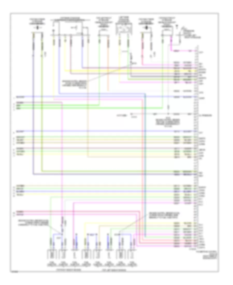
5.0L FLEX FUEL
5.0L Flex Fuel, Engine Performance Wiring Diagram (1 of 6) for Ford F-150 King Ranch 2013
List of elements for 5.0L Flex Fuel, Engine Performance Wiring Diagram (1 of 6) for Ford F-150 King Ranch 2013:
- (engine control sensor wiring harness, near breakout to c144)
- (engine control sensor wiring harness, near breakout to g101)
- (front of engine compt) ambient air temperature sensor
- A/c pressure transducer (right front of engine compt)
- Aat
- Accelerator pedal position (app) sensor (top of brake pedal assembly)
- Accr
- Acpt
- Air conditioning system
- App 1
- App vrfe
- App2
- Apprtn
- Apprtn2
- Appvref2
- Battery junction box (bjb) (front of engine compt)
- Bcs2 alt
- Bpp
- Bps
- C1381b
- C1581
- C210
- Canv
- Cbb53
- Cbb75
- Ccb08
- Cdc10
- Cdc12
- Cdc15
- Cdc35
- Cdc54
- Ce114
- Ce436
- Ce607
- Ce608
- Cec01
- Cec02
- Ces09
- Cet42
- Cet43
- Ch302
- Computer data lines system
- Cooling fans system
- Digital
- Fpc
- Fpm
- Ftp
- Ftpref
- Fuse 10a
- Fuse 5a
- G100 (right side of engine compt)
- Gd113
- Gencom
- Genmon
- Hfc
- Hot at all times
- Hot in start or run
- Hs can +
- Hs can -
- Iat
- Injpwrm
- Ispr
- Kapwr
- Le136
- Le137
- Le230
- Le424
- Lfc
- Maf
- Mass air flow/ intake air temperature sensor (left front of engine compt)
- Pcm wake
- Pcmrc
- Powertrain control module (right rear of engine compt)
- Pwr gnd
- Re136
- Re137
- Re320
- Re407
- S101
- S162
- S169
- Sbb26
- Sigrtn
- Smc
- Smcs
- Sst-d
- Sst-u
- Start
- Starting/charging system
- Vdb04
- Vdb05
- Vdc61
- Ve225
- Ve518
- Ve701
- Ve702
- Ve740
- Ve750
- Ve807
- Ve922
- Vh433
- Vpwr
- Vref
- Vref 5v
5.0L Flex Fuel, Engine Performance Wiring Diagram (2 of 6) for Ford F-150 King Ranch 2013
List of elements for 5.0L Flex Fuel, Engine Performance Wiring Diagram (2 of 6) for Ford F-150 King Ranch 2013:
- (engine control sensor wiring harness, near breakout to body control module) s240
- (engine control sensor wiring harness, near breakout to mass air flow/intake air temperature sensor)
- (ignition switch assembly) passive anti-theft transceiver
- (right front corner of engine compt) generator current sensor
- (tail lamps wiring harness, in breakout to fuel pump control module) s407
- (under left center of vehicle) evaporative emission canister vent solenoid
- Bcs2 alt
- Body control module (right kick panel)
- Brake pedal position (bpp) switch (left side of dash)
- C1581
- C192
- C210
- C214
- C2280f
- C310a
- Ce515
- Ce608
- Cr167
- Ens
- Exterior lights system
- Fp pwr
- Fp rtn
- Fpc
- Fpm
- Fuel pump (fet)
- Fuel pump (fp) control module (near fuel tank)
- Fuel tank pressure (ftp) sensor (fuel tank assembly)
- Fuse 10a
- G102 (left front of engine compt)
- G401 (under rear of vehicle, above spare tire)
- Gd117
- Gnd
- Hot at all times
- Micro
- Pcm wake up (fet)
- Re515
- Restraints control module (rcm) (under center console)
- S107
- S112
- S410
- Sigrtn
- Ve225
- Ve518
- Vpwr
- Vref
5.0L Flex Fuel, Engine Performance Wiring Diagram (3 of 6) for Ford F-150 King Ranch 2013
List of elements for 5.0L Flex Fuel, Engine Performance Wiring Diagram (3 of 6) for Ford F-150 King Ranch 2013:
- (backup lamp switch to rear lamp feed wiring harness, near breakout to c140)
- Battery junction box (bjb) (front of engine compt)
- C140
- C146
- C1581
- C210
- Ce515
- Computer data lines system
- Fuel gauge sensor
- Fuel level 1
- Fuel pump
- Fuel pump (fp) module (fuel tank assembly)
- Fuel pump relay
- Fuse 15a
- Fuse 20a
- Fuse 40a
- G401 (under rear of vehicle, above spare tire)
- Heated oxygen sensor (ho2s) 12 (engine exhaust pipe)
- Heated oxygen sensor (ho2s) 22 (engine exhaust pipe)
- Hot at all times
- Hs can +
- Hs can -
- Instrument panel cluster (ipc)
- Nca
- Pcm power relay
- Re515
- Rmc32
- Rtn fuel level 1
- S103
- S111
- S125
- S129
- S148
- S410
- Universal heated oxygen sensor 11 (engine exhaust pipe)
- Universal heated oxygen sensor 21 (engine exhaust pipe)
- Vmc11
5.0L Flex Fuel, Engine Performance Wiring Diagram (4 of 6) for Ford F-150 King Ranch 2013
List of elements for 5.0L Flex Fuel, Engine Performance Wiring Diagram (4 of 6) for Ford F-150 King Ranch 2013:
- (w/ column shifter) tow haul switch
- 6r80 transmission
- Body control module (right kick panel)
- C1381t
- C140
- C211
- C214
- C2280b
- C264
- C329
- Ce233
- Ce234
- Ce235
- Ce236
- Cet05
- Cet06
- Cet07
- Cet08
- Cet09
- Cet10
- Cet18
- Cet25
- Cet34
- Floor shifter (w/ floor shifter)
- Fuse 5a
- Ho2s12
- Ho2s22
- Hot in start or run
- Htr12
- Htr22
- Le111
- Le448
- Le449
- Le450
- Le451
- Le452
- Le453
- Lpc
- Nca
- Oss
- Powertrain control module (right rear of engine compt)
- R/s
- Re405
- Re406
- Ret24
- Sigrtn
- Ssa
- Ssb
- Ssc
- Ssd
- Sse
- Sst-d
- Sst-u
- Tcc
- Tft
- Tows
- Tr gnd
- Tr p
- Tr-p
- Transmission control switch
- Tspc
- Tss
- Tss/oss vpwr
- Uo2s11
- Uo2s21
- Uo2sgref11
- Uo2sgref21
- Uo2shtr11
- Uo2shtr21
- Uo2spc11
- Uo2spc21
- Uo2spct11
- Ve731
- Ve733
- Ve826
- Ve827
- Vet26
- Vet27
- Vet32
- Vet33
- Vpwr
- W/ column shifter
- W/ floor shifter
5.0L Flex Fuel, Engine Performance Wiring Diagram (5 of 6) for Ford F-150 King Ranch 2013
List of elements for 5.0L Flex Fuel, Engine Performance Wiring Diagram (5 of 6) for Ford F-150 King Ranch 2013:
- (engine control sensor & fuel charge wiring harness, near breakout to c1019)
- (engine control sensor wiring harness, near breakout to fuel injector 3)
- (left side of oil pan) low oil level switch
- (rear of left cylinder head) camshaft position sensor 21
- (rear of left cylinder head) camshaft position sensor 22
- (rear of right cylinder head) camshaft position sensor 11
- (rear of right cylinder head) camshaft position sensor 12
- (rear of right cylinder head) cylinder head temperature sensor
- (top left side of engine)
- (top right side of engine)
- Coil on plug (cop) 1
- Coil on plug (cop) 2
- Coil on plug (cop) 3
- Coil on plug (cop) 4
- Coil on plug (cop) 5
- Coil on plug (cop) 6
- Coil on plug (cop) 7
- Coil on plug (cop) 8
- Evaporative emission canister purge valve (top front of engine)
- Ignition transformer capacitor 1 (top right rear of engine)
- S104
- S135
- S136
- S139
- S173
- Variable camshaft timing 12 solenoid (top right front of engine)
5.0L Flex Fuel, Engine Performance Wiring Diagram (6 of 6) for Ford F-150 King Ranch 2013
List of elements for 5.0L Flex Fuel, Engine Performance Wiring Diagram (6 of 6) for Ford F-150 King Ranch 2013:
- (engine control sensor & fuel charge wiring harness, in breakout to coil on plug 7)
- (engine control sensor & fuel charge wiring harness, near breakout to fuel injector 2)
- (engine control sensor & fuel charge wiring harness, near breakout to powertrain control module)
- (not used) c146
- (right rear of engine) crankshaft position sensor
- (top front of engine) electronic throttle control
- (top left front of engine) variable camshaft timing 21 solenoid
- (top left rear of engine) knock sensor 2
- (top left side of engine)
- (top right front of engine) variable camshaft timing 11 solenoid
- (top right rear of engine) knock sensor 1
- (top right side of engine)
- C1019
- C1381e
- C146
- Ce113
- Ce205
- Ce206
- Ce207
- Ce208
- Ce209
- Ce210
- Ce211
- Ce212
- Ce303
- Ce304
- Ce305
- Ce306
- Ce307
- Ce308
- Ce309
- Ce310
- Ce412
- Ce421
- Ce422
- Ce426
- Ce442
- Ce443
- Cht
- Ckp+
- Ckp-
- Cmc24
- Cmp11
- Cmp12
- Cmp21
- Cmp22
- Cop1a
- Cop2h
- Cop3f
- Cop4c
- Cop5b
- Cop6e
- Cop7g
- Cop8d
- De135
- Eol
- Etcref
- Etcrtn
- Evapcp
- Fuel injector
- Inj 1
- Inj 2
- Inj 3
- Inj 4
- Inj 5
- Inj 6
- Inj 7
- Inj 8
- Ks1+
- Ks1-
- Ks2+
- Ks2-
- Le111
- Le134
- Le142
- Nca
- Oil pressure
- Oil pressure switch (lower left front of engine)
- Powertrain control module (right rear of engine compt)
- Re134
- Re135
- Re323
- Re324
- Re405
- Re429
- S116 (engine control sensor & fuel charge wiring harness, near breakout to c146)
- S134
- S137
- S138
- Shdrtn
- Sigrtn
- Tacm+
- Tacm-
- Tp1
- Tp2
- Variable camshaft timing 22 solenoid (top left front of engine)
- Vbpwr
- Vct11
- Vct12
- Vct21
- Vct22
- Ve706
- Ve707
- Ve711
- Ve712
- Ve736
- Ve738
- Ve801
- Ve802
- Ve818
- Ve819
- Vrsrtn
- Vrsrtn2
6.2L
6.2L, Engine Performance Wiring Diagram (1 of 6) for Ford F-150 King Ranch 2013
List of elements for 6.2L, Engine Performance Wiring Diagram (1 of 6) for Ford F-150 King Ranch 2013:
- (engine control sensor wiring harness, near breakout to c144)
- (engine control sensor wiring harness, near near breakout to g101)
- (front of engine compt) ambient air temperature sensor
- A/c pressure transducer (right front of engine compt)
- Aat
- Accelerator pedal position (app) sensor (top of brake pedal assembly)
- Accr
- Acpt
- Air conditioning system
- App1
- App2
- Apprtn
- Apprtn2
- Appvref
- Appvref2
- Battery junction box (bjb) (front of engine compt)
- Bpp
- Bps
- C1381b
- C1581
- C210
- Canv
- Cbb53
- Cbb75
- Ccb08
- Cdc10
- Cdc12
- Cdc15
- Cdc35
- Cdc54
- Ce114
- Ce436
- Ce607
- Ce608
- Cec01
- Cec02
- Ces09
- Cet42
- Cet43
- Ch302
- Computer data lines system
- Cooling fans system
- Digital
- Fpc
- Fpm
- Ftp
- Ftpref
- Fuse 10a
- Fuse 5a
- G100 (right side of engine compt)
- Gd113
- Gencom
- Genmon
- Hfc
- Hot at all times
- Hot in start or run
- Hs can +
- Hs can -
- Iat
- Injpwrm
- Ispr
- Kapwr
- Le136
- Le137
- Le230
- Le424
- Lfc
- Maf
- Mass air flow/ intake air temperature sensor (left front of engine compt)
- Pcm wake
- Pcmrc
- Powertrain control module (right rear of engine compt)
- Pwr gnd
- Re136
- Re137
- Re320
- Re407
- S101
- S162
- S169
- Sbb26
- Sigrtn
- Smc
- Smcs
- Sst-d
- Sst-u
- Start
- Starting/charging system
- Vdb04
- Vdb05
- Ve225
- Ve518
- Ve701
- Ve702
- Ve740
- Ve750
- Ve807
- Ve922
- Vh433
- Vpwr
- Vref
- Vref 5v
6.2L, Engine Performance Wiring Diagram (2 of 6) for Ford F-150 King Ranch 2013
List of elements for 6.2L, Engine Performance Wiring Diagram (2 of 6) for Ford F-150 King Ranch 2013:
- (engine control sensor wiring harness, near breakout to body control module) s240
- (engine control sensor wiring harness, near breakout to mass air flow/intake air temperature sensor)
- (ignition switch assembly) passive anti-theft transceiver
- (tail lamps wiring harness, in breakout to fuel pump control module) s407
- (under left center of vehicle) evaporative emission canister vent solenoid
- Body control module (right kick panel)
- Brake pedal position (bpp) switch (left side of dash)
- C1581
- C210
- C214
- C2280f
- C310a
- Ce515
- Ce608
- Cr167
- Ens
- Exterior lights system
- Fp pwr
- Fp rtn
- Fpc
- Fpm
- Fuel pump (fet)
- Fuel pump (fp) control module (near fuel tank)
- Fuel tank pressure (ftp) sensor (fuel tank assembly)
- Fuse 10a
- G102 (left front of engine compt)
- G401 (under rear of vehicle, above spare tire)
- Gd117
- Gnd
- Hot at all times
- Micro
- Pcm wake up (fet)
- Re515
- Restraints control module (rcm) (under center console)
- S107
- S112 (engine control sensor wiring harness, near breakout to c110)
- S410
- Ve225
- Ve518
- Vpwr
6.2L, Engine Performance Wiring Diagram (3 of 6) for Ford F-150 King Ranch 2013
List of elements for 6.2L, Engine Performance Wiring Diagram (3 of 6) for Ford F-150 King Ranch 2013:
- (backup lamp switch to rear lamp feed wiring harness, near breakout to c140)
- Battery junction box (bjb) (front of engine compt)
- C1010
- C140
- C1581
- C210
- Ce515
- Computer data lines system
- Fuel gauge sensor
- Fuel level 1
- Fuel level1 rtn
- Fuel pump
- Fuel pump module (fuel tank assembly)
- Fuel pump relay
- Fuse 15a
- Fuse 20a
- Fuse 40a
- G401 (under rear of vehicle, above spare tire)
- Heated oxygen sensor (ho2s) 12 (engine exhaust pipe)
- Heated oxygen sensor (ho2s) 22 (engine exhaust pipe)
- Hot at all times
- Hs can +
- Hs can -
- Instrument panel cluster (ipc)
- Nca
- Pcm power relay
- Re515
- Rmc32
- S103
- S111
- S125
- S129
- S148
- S410
- Universal heated oxygen sensor 11 (engine exhaust pipe)
- Universal heated oxygen sensor 21 (engine exhaust pipe)
- Vmc11
6.2L, Engine Performance Wiring Diagram (4 of 6) for Ford F-150 King Ranch 2013
List of elements for 6.2L, Engine Performance Wiring Diagram (4 of 6) for Ford F-150 King Ranch 2013:
- (w/ column shifter) tow haul switch
- 6r80 transmission
- Body control module (right kick panel)
- C1381t
- C140
- C211
- C214
- C2280b
- C264
- C329
- Ce233
- Ce234
- Ce235
- Ce236
- Cet05
- Cet06
- Cet07
- Cet08
- Cet09
- Cet10
- Cet18
- Cet25
- Cet34
- Floor shifter (w/ floor shifter)
- Fuse 5a
- Ho2s12
- Ho2s22
- Hot in start or run
- Htr12
- Htr22
- Le111
- Le448
- Le449
- Le450
- Le451
- Le452
- Le453
- Lpc
- Nca
- Oss
- Powertrain control module (right rear of engine compt)
- R/s
- Re405
- Re406
- Ret24
- Sigrtn
- Ssa
- Ssb
- Ssc
- Ssd
- Sse
- Sst-d
- Sst-u
- Tcc
- Tft
- Tows
- Tr gnd
- Tr p
- Tr-p
- Transmission control switch
- Tspc
- Tss
- Tss/oss vpwr
- Uo2s11
- Uo2s21
- Uo2sgref11
- Uo2sgref21
- Uo2shtr11
- Uo2shtr21
- Uo2spc11
- Uo2spc21
- Uo2spct11
- Ve731
- Ve733
- Ve826
- Ve827
- Vet26
- Vet27
- Vet32
- Vet33
- Vpwr
- W/ column shifter
- W/ floor shifter
6.2L, Engine Performance Wiring Diagram (5 of 6) for Ford F-150 King Ranch 2013
List of elements for 6.2L, Engine Performance Wiring Diagram (5 of 6) for Ford F-150 King Ranch 2013:
- (rear of left cylinder head) camshaft position sensor 1
- (rear of right cylinder head) cylinder head temperature sensor
- (top left side of engine)
- (top right side of engine)
- C133
- Camshaft position sensor 2
- Coil on plug (cop) 1
- Coil on plug (cop) 2
- Coil on plug (cop) 3
- Coil on plug (cop) 4
- Coil on plug (cop) 5
- Coil on plug (cop) 6
- Coil on plug (cop) 7
- Coil on plug (cop) 8
- Evaporative emission canister purge valve (top rear of engine)
- Ignition transformer capacitor 1 (top right front of engine)
- Ignition transformer capacitor 2 (top left front of engine)
- S104 (near breakout to evaporative emission canister purge valve)
- S135
- S136
- S139
- S173 (engine control sensor & fuel charge wiring harness, near breakout to c133)
6.2L, Engine Performance Wiring Diagram (6 of 6) for Ford F-150 King Ranch 2013
List of elements for 6.2L, Engine Performance Wiring Diagram (6 of 6) for Ford F-150 King Ranch 2013:
- (engine control sensor & fuel charge wiring harness, in breakout to fuel injector 3)
- (engine control sensor & fuel charge wiring harness, near breakout to c146)
- (engine control sensor & fuel charge wiring harness, near breakout to fuel injector 6)
- (left rear of engine) crankshaft position sensor
- (not used)
- (top left front of engine) variable camshaft timing 2 solenoid
- (top left side of engine)
- (top rear of engine) electronic throttle control
- (top right front of engine) variable camshaft timing 1 solenoid
- (top right rear of engine) knock sensor 1
- (top right rear of engine) knock sensor 2
- (top right side of engine)
- C1010
- C133
- C1381e
- Ce113
- Ce205
- Ce206
- Ce207
- Ce208
- Ce209
- Ce210
- Ce211
- Ce212
- Ce303
- Ce304
- Ce305
- Ce306
- Ce307
- Ce308
- Ce309
- Ce310
- Ce412
- Ce421
- Ce422
- Ce426
- Cht
- Ckp+
- Ckp-
- Cmc24
- Cmp1
- Cmp2
- Cop1a
- Cop2h
- Cop3f
- Cop4c
- Cop5b
- Cop6e
- Cop7g
- Cop8d
- De135
- Etcref
- Etcrtn
- Evapcp
- Fuel injector
- Inj 1
- Inj 2
- Inj 3
- Inj 4
- Inj 5
- Inj 6
- Inj 7
- Inj 8
- Ks1+
- Ks1-
- Ks2+
- Ks2-
- Le111
- Le134
- Nca
- Oil pressure
- Oil pressure switch (lower left front of engine)
- Powertrain control module (right rear of engine compt)
- Re134
- Re135
- Re323
- Re324
- Re405
- S116 (engine control sensor and fuel charge wiring harness, near breakout to c146)
- S134
- S137
- S138
- Shdrtn
- Sigrtn
- Tacm+
- Tacm-
- Tp1
- Tp2
- Vbpwr
- Vct1
- Vct2
- Ve711
- Ve712
- Ve736
- Ve738
- Ve801
- Ve802
- Ve818
- Ve819
EXTERIOR LIGHTS
Backup Lamps Wiring Diagram for Ford F-150 King Ranch 2013
List of elements for Backup Lamps Wiring Diagram for Ford F-150 King Ranch 2013:
- (engine control sensor and fuel charge wiring harness, near breakout to fuel rail pressure sensor) (3.5l) s173
- (engine control sensor wiring harness, near breakout to left front wheel speed sensor) s120
- (w/ rear view camera) auto-dimming interior mirror
- 3.5l
- 3.7l
- 5.0l/6.2l
- 6r80 transmission
- Battery junction box (bjb) (front of engine compt)
- Body control module (right kick panel)
- C134
- C1381b
- C1381t
- C1551b
- C1551e
- C175b
- C175t
- C212
- C2280d cls28
- C2280f vdb05
- C314
- C405
- C406
- Computer data lines system
- Fuse 15a
- G101 (right front of engine compt)
- G401 (under rear of vehicle, above spare tire)
- Hot at all times
- Hs can +
- Hs can -
- Left reversing lamp
- Micro
- Powertrain control module (right rear of engine compt)
- Re405
- Ret24
- Rev lamp (fet)
- Reversing lamps relay
- Right reversing lamp
- S106
- S111 (3.7l) (backup lamp switch to rear lamp feed wiring harness, near breakout to c140)
- S404
- Sigrtn
- Tr gnd
- Trailer tow connector (w/ 7 pin trailer tow) (rear of vehicle)
- Trp
- Vdb04
- Vdb05
- Vet32
Exterior Lamps Wiring Diagram (1 of 2) for Ford F-150 King Ranch 2013
List of elements for Exterior Lamps Wiring Diagram (1 of 2) for Ford F-150 King Ranch 2013:
- (engine control sensor wiring harness, near breakout to battery junction box) s108
- (left front of engine compt) g102
- (w/ power equipment) driver side exterior rear view mirror
- (w/ power equipment) passenger side exterior rear view mirror
- Body control module (right kick panel)
- C145
- C1595
- C212
- C215
- C219
- C2280b
- C2280c
- C2280d
- C2280e
- C2280f
- C237
- Can + hs
- Can - hs
- Center front marker lamp (svt raptor)
- Cls32
- Computer data lines system
- Fuse 10a
- Fuse 15a
- G101 (right front of engine compt)
- G102 (left front of engine compt)
- G200 (left kick panel)
- G201 (right kick panel)
- G202 (left side of dash)
- Hazard
- Hazard/pad/ traction switch
- High mounted stoplamp
- Hot at all times
- If equipped
- Left center front marker lamp (svt raptor)
- Left front marker lamp (svt raptor)
- Left front park/turn lamp
- Left front side lamp
- Lf turn lamp (fet)
- Lh cor- ner lamp (fet)
- Lr stop/ turn lamp (fet)
- Micro
- Nca
- Park
- Park lamp relay
- Puddle lamp (fet)
- Rf turn lamp (fet)
- Rh cor- ner lamp (fet)
- Right center front marker lamp (svt raptor)
- Right front marker lamp (svt raptor)
- Right front park/turn lamp
- Right front side lamp
- Rr stop/ turn lamp (fet)
- S198 (svt grille led jumper wiring assembly, near breakout to left center front marker lamp)
- S348 (w/ power equipment) (near breakout to g300)
- S500
- S600
- Stop/ chmsl (fet)
- Svt raptor
- Turn
- Vdb04
- Vdb05
- W/ front camera
- W/ hmi
- W/o front camera
- W/o hmi
Exterior Lamps Wiring Diagram (2 of 2) for Ford F-150 King Ranch 2013
List of elements for Exterior Lamps Wiring Diagram (2 of 2) for Ford F-150 King Ranch 2013:
- (engine control sensor wiring harness, near breakout to battery junction box) s168
- (engine control sensor wiring harness, near breakout to c110)
- (engine control sensor wiring harness, near breakout to mass air flow/intake air temperature sensor)
- (front of engine compt) battery junction box (bjb)
- (left front of engine compt) g102
- (left side of dash) g203
- (rear lamp connector wiring harness, near breakout to c405) s400
- (rear lamp connector wiring harness, near breakout to c405) s401
- (taped to harness near c127)
- 3.5l
- 3.7l
- 5.0l/6.2l
- Auto
- Auto lamp on
- Battery junction box (bjb) (front of engine compt)
- Body control module (right kick panel)
- Bpp
- Bps
- Brake pedal position (bpp) switch (left side of dash)
- C-sigrtn
- C134
- C1381b
- C1551b
- C1581
- C175b
- C2108
- C213
- C215
- C2280a
- C2280b
- C2280f
- C2403
- C2414a
- C2414b
- C264
- C405
- Ccb08
- Ces09
- Clf19
- Clf21
- Clf23
- Clf24
- Cls32
- Cls34
- Computer data lines system
- Fog
- Fog illum
- Fog lamp
- Front controls interface module
- Fuse 10a
- Fuse 15a
- Fuse 5a
- G202 (left side of dash)
- G401 (under rear of vehicle, above spare tire)
- Gd133
- Gd138
- Gnd
- Hazard
- Hdlp off
- Hdlp on
- Head
- Headlamp switch
- Headlights system
- Hot at all times
- Hs can +
- Hs can -
- Hs can+
- Hs can-
- I can+
- I can-
- Instrument panel cluster (ipc)
- Left license plate lamp
- Left rear marker lamp (svt raptor)
- Left rear park/stop/ turn lamp 1
- Left rear park/stop/ turn lamp 2
- Left turn trailer tow relay
- Logic gnd
- Micro
- Multi- function switch
- Off
- Park
- Park lamp on
- Parking lamp trailer tow relay
- Powertrain control module (right rear of engine compt)
- Pwr gnd
- Re407
- Red
- Right license plate lamp
- Right rear marker lamp (svt raptor)
- Right rear park/stop/ turn lamp 1
- Right rear park/stop/ turn lamp 2
- Right turn trailer tow relay
- S112 (engine control sensor wiring harness, near breakout to c110)
- S126 (engine control sensor wiring harness, near breakout to battery junction box)
- S127
- S167
- S212 (w/ adjustable pedal/tilt/ telescope column)
- S220
- S404
- S405 (rear lamp connector wiring harness, near breakout to left license plate lamp)
- S408
- S409
- Sbp09
- Sbp23
- Sbp24
- Shift interlock system
- Steering column control module (sccm) (steering column)
- Trailer brake control (tbc) module (left side of dash)
- Vbatt
- Vdb04
- Vdb05
- Vdb13
- Vdb14
- W/ column shifter
- W/ crew chief
Trailer/Camper Adapter Wiring Diagram for Ford F-150 King Ranch 2013
List of elements for Trailer/Camper Adapter Wiring Diagram for Ford F-150 King Ranch 2013:
- (engine control sensor wiring harness, near breakout to battery junction box) s126
- (front of engine compt) battery junction box (bjb)
- (or boo)
- (or cbp37)
- (or tbo)
- (or vb-a)
- (or vdb04)
- (or vdb05)
- (taped to harness near c127)
- 4-pin trailer tow
- 7-pin trailer tow
- Backup lamps circuit
- Battery charge trailer tow relay
- Body control module (right kick panel)
- Bpp
- Brake
- C134
- C1581
- C2108
- C211
- C212
- C215
- C2280b
- C2280d
- C2280f
- C406
- C439a
- C439b
- Cat06
- Cat09
- Cat14
- Cat16
- Cat17
- Cat19
- Cbp31
- Computer data lines system
- Crew chief
- Crew chief w/ factory installed
- End in harness
- Energy mgt (fet)
- Except crew chief w/ factory installed & trailer tow kit
- Exterior lamps circuit
- Factory installed
- Fuse 10a
- Fuse 15a
- Fuse 20a
- Fuse 30a
- Fuse 5a
- G101 (right front of engine compt)
- G203 (left side of dash)
- G400 (under rear of vehicle)
- Gd138
- Gnd
- Hot at all times
- Hot in start or run
- Hs can +
- Hs can -
- Hsc1-a
- Hsc2-a
- Igrun-a
- Left turn trailer tow relay
- Lr stop/ turn lamp (fet)
- Micro
- Not used
- Park lamp relay
- Parking lamp trailer tow relay
- Power distribution system
- Rat08
- Red
- Rev lamp (fet)
- Rever- sing lamp relay
- Right turn trailer tow relay
- Rr stop/ turn lamp (fet)
- S106
- S118
- S120 (engine control sensor wiring harness, near breakout to left front wheel speed sensor)
- S127 (engine control sensor wiring harness, near breakout to mass air flow/ intake air temperature sensor)
- S168 (engine control sensor wiring harness, near breakout to battery junction box)
- S272 (crew chief)
- S273
- S274 (crew chief)
- S347 (body main wiring harness, near breakout to left running board motor)
- Sbb17
- Trailer brake control (tbc) module (left side of dash)
- Trailer tow connector (4-pin trailer tow) (rear of vehicle)
- Trailer tow connector (7-pin trailer tow) (rear of vehicle)
- Trailer tow kit w/o crew chief
- Vbatt
- Vpwr
GROUND DISTRIBUTION
Ground Distribution Wiring Diagram (1 of 5) for Ford F-150 King Ranch 2013
List of elements for Ground Distribution Wiring Diagram (1 of 5) for Ford F-150 King Ranch 2013:
- (end in harness near c127)
- (except 3.5l) brake pedal position (bpp) switch
- (left rear corner of engine compt) (svt raptor) auxiliary battery junction box (bjb)
- (svt raptor) camera switching module
- (svt raptor) front video camera
- (w/ svt raptor) right front marker lamp
- (w/ sync) accessory protocol interface module (apim)
- (w/ sync) global positioning system module (gpsm)
- (w/o in-dash computer) audio control module (acm)
- 3.5l
- 3.7l
- 4-pin trailer tow
- 5.0l & 6.2l
- 7-pin trailer tow
- Anti-theft hood switch
- Base audio
- Battery
- Brake fluid level switch
- C1381b
- C145
- C1551b
- C1581
- C175b
- C240a
- C290a
- C4000
- C405
- Front camera washer relay
- G100 (right side of engine compt)
- G102 (left front of engine compt)
- G106 (bottom right side of engine)
- G107 (right side of engine compt)
- G108 (right side of engine compt)
- G112
- G204 (behind center of dash)
- G400 (under rear of vehicle)
- Head-up display (hud) module
- Left fog lamp
- Left front side lamp
- Left headlamp
- Mid box
- Nca
- Parking brake switch
- Powertrain control module (pcm)
- Premium audio
- Premium audio w/ sync
- Right front park/turn lamp
- S215 (main wiring harness, in breakout to hazard/pad/traction switch)
- Trailer tow connector
- Upfitter relay 1
- Upfitter relay 2
- Upfitter relay 3
- Upfitter relay 4
- Video camera
- W/ 4 inch display
- W/ base audio
- W/ hid
- W/o hid
- W/o svt raptor
- Windshield washer pump motor
- Windshield wiper motor
Ground Distribution Wiring Diagram (2 of 5) for Ford F-150 King Ranch 2013
List of elements for Ground Distribution Wiring Diagram (2 of 5) for Ford F-150 King Ranch 2013:
- (automatic a/c) eatc hvac module
- (front of engine compt) battery junction box (bjb)
- (if equipped) electronic locking differential (eld) field coil
- (if equipped) rain sensor module
- (main wiring harness, near breakout to transfer case control module)
- (manual a/c) emtc hvac module
- (steering wheel harness near breakout to horn switch)
- (w svt raptor) left front marker lamp
- (w/ adjustable pedal/steering column switch) steering column control module (sccm)
- (w/ ambient lighting)
- (w/ column shifter) brake shift interlock
- (w/ hmi) center stack switch assembly
- (w/o navigation) front display interface module (fdim)
- 6.2l
- A/c compressor clutch field coil
- Auto-dimming interior mirror
- Battery junction box (bjb) (front of engine compt)
- Body control module (bcm)
- C1010
- C145
- C1581
- C1595
- C192
- C218a
- C218b
- C2280d
- C228a
- C228c
- C2371b
- C238
- C2414a
- C248
- C294a
- C314
- Center front marker lamp
- Clock- spring (steering wheel)
- Cooling fan relay
- Data link connector (dlc)
- Electronic compass
- Engine cooling fan motor 2
- Except 6.2l
- Front controls interface module (fcim)
- G101 (right front of engine compt)
- G202 (left side of dash)
- Hazard/pad/ traction switch
- Headlamp switch
- Horn
- Horn switch
- Instrument panel cluster (ipc)
- Left center front marker lamp
- Left front park/turn lamp
- Left steering wheel switch
- Left turn trailer tow relay
- Mode select switch (mss)
- Nca
- Parking lamp trailer tow relay
- Passive anti-theft transceiver
- Reversing lamp relay
- Right center front marker lamp
- Right fog lamp
- Right front side lamp
- Right headlamp
- Right steering wheel switch
- Right turn trailer tow relay
- S199 (svt grille led jumper wiring assembly, near breakout to center front marker lamp)
- S260 (main wiring harness, in breakout front display interface module)
- S299 nca
- S905 (dome lamp connector wiring harness, near breakout to rear interior/map lamps assembly)
- Tire pressure monitor (tpm) module
- To ground g203 (diagram 5 of 5)
- Transfer case control module (tccm)
- W/ electronic shift on the fly
- W/ front camera
- W/ hmi
- W/ o hid w/ hid
- W/ rain sensor
- W/ svt raptor
- W/o auto dimming interior mirror
- W/o front camera
- W/o hmi
- Wiper relay
Ground Distribution Wiring Diagram (3 of 5) for Ford F-150 King Ranch 2013
List of elements for Ground Distribution Wiring Diagram (3 of 5) for Ford F-150 King Ranch 2013:
- (if equipped)
- (if equipped) power mirror fold module
- (if equipped) telescoping exterior rear view mirror switch
- (left front door window regulator wiring harness, near breakout to left front speaker)
- (super cab) left front door latch
- (super cab) left rear door ajar switch
- (w/ memory) driver seat module (dsm)
- (w/ memory) driver side front seat control switch
- (w/ memory) memory set switch
- (w/o memory) driver side front seat control switch
- C1463a
- C219
- C300
- C3050
- C311
- C3162b
- C3205
- C327
- C341a
- C341b
- C405
- C535b
- Coil on plug (cop) 1
- Coil on plug (cop) 2
- Coil on plug (cop) 3
- Coil on plug (cop) 4
- Coil on plug (cop) 5
- Coil on plug (cop) 6
- Control module)
- Driver side exterior rear view mirror
- Driver side seat backrest heater mat
- Exterior rear view mirror switch
- Fuel pump control module
- Fuel pump control module shield
- G104 (3.5l) (rear of right cylinder head)
- G105 (3.5l) (left side of engine)
- G109 (right side of engine compt)
- G200 (left kick panel)
- G401 (under rear of vehicle, above spare tire)
- Keyless entry keypad
- Left front door lock switch
- Left front power window motor
- Left license plate lamp
- Left rear door latch
- Left rear heated seat module
- Left rear marker lamp
- Left rear park/stop/ turn lamp 1
- Left rear park/stop/ turn lamp 2
- Left rear seat back heater
- Left rear seat heated switch
- Left reversing lamp
- Master window control switch
- Nca
- Parking aid module (pam)
- Power steering control module (pscm)
- Regular cab
- Right license plate lamp
- Right rear marker lamp
- Right rear park/stop/ turn lamp 1
- Right rear park/stop/ turn lamp 2
- Right reversing lamp
- S164 (engine control sensor & fuel charge wiring harness, near breakout to coil on plug 3)
- S165 (engine control sensor & fuel charge wiring harness, near breakout to coil on plug 6)
- S352 (driver seat wiring harness, near breakout to driver seat front height motor)
- S372 (driver side crew cab rear seat wiring assembly, in breakout to c3205)
- S404 (rear lamp connector wiring harness, near breakout to left license plate lamp)
- S409 (rear lamp connector wiring harness, in breakout to c405)
- S412 (tail lamps wiring harness, in breakout to fuel pump control module)
- S500
- S700 (if equipped) (left rear door window regulator wiring harness, near breakout to left rear door latch)
- Super crew
- Super crew cab
- Super crew/ super cab
- W/ power equipment
- W/ svt raptor
- W/o memory & rear parking aid
- W/o power equipment
Ground Distribution Wiring Diagram (4 of 5) for Ford F-150 King Ranch 2013
List of elements for Ground Distribution Wiring Diagram (4 of 5) for Ford F-150 King Ranch 2013:
- & super cab w/ remote keyless entry
- (if equipped)
- (if equipped) roof opening panel module
- (regular cab w/o power equipment) left front door latch
- (super cab) right rear door ajar switch
- (w/ climate controlled seats) dual climate controlled seat module (dcsm)
- (w/ column shifter) console 2 power point
- Anti-lock brake system (abs) module
- Body control module
- C219 (if equipped)
- C2280d
- C237 (if equipped)
- C312
- C313
- C314
- C315
- C316
- C3206
- C3265a
- C3313b
- C340
- Front dome lamp
- Front interior/map lamps assembly
- G103 (left front of engine compt)
- G110 (5.0l) (front of right cylinder bank)
- G111 (5.0l) (top front of right cylinder bank)
- G201 (right kick panel)
- High mounted stop lamp
- Left vanity mirror lamp
- Nca
- Near breakout to c3159)
- Overhead console switch assembly
- Passenger side exterior rear view mirror
- Passenger side front seat control switch
- Passenger side seat backrest heater mat
- Passenger side window control switch
- Power running board (prb) module
- Rear interior/map lamps assembly
- Regular cab
- Regular cab w/o remote keyless entry
- Right front door latch
- Right front door lock switch
- Right front power window motor
- Right rear door latch
- Right rear seat back heater
- Right rear seat heated switch
- Right vanity mirror lamp
- S600 (right front door window regulator wiring harness, near breakout to right front door latch)
- S800 (if equipped) (right rear door window regulator wiring harness, near breakout to right rear door latch)
- S903 (dome lamp connector wiring harness, near breakout to left vanity mirror lamp)
- Super crew
- W/ overhead console
- W/ power equipment
- W/o moonroof
- W/o power equipment
Ground Distribution Wiring Diagram (5 of 5) for Ford F-150 King Ranch 2013
List of elements for Ground Distribution Wiring Diagram (5 of 5) for Ford F-150 King Ranch 2013:
- (crew chief) telematics module
- (except crew chief) trailer brake control (tbc) module
- (regular cab & super crew cab) passenger safety belt tension sensor (bts)
- (super cab) passenger safety belt tension sensor (bts)
- (w/ 110v power inverter) dc/ac inverter module
- (w/ adjustable pedal/tilt/telescope column switch) steering column control module (sccm)
- (w/ column shifter)
- (w/ sony sound) audio digital signal processing (dsp) module
- (w/ svt raptor) hill descent control switch
- (w/ svt raptor) off-road mode switch
- (w/ svt raptor) upfitter switch
- Blower motor resistor
- Blower motor speed control
- C2108
- C2293a
- C2414b
- C264
- C29413
- C311
- C312
- C3154c
- C316
- C329
- Console 1 power point
- Console 2 power point
- Driver safety belt buckle switch
- Driver seat position sensor
- Emtc hvac module
- Floor shifter
- From ground g202 (diagram 2 of 5)
- Front cigar lighter
- G203 (left side of dash)
- G300 (under center console)
- G301 (left "b" pillar)
- If equipped
- Instrument panel power point
- Manual a/c
- Nca
- Occupant classification system module (ocsm)
- Passenger safety belt buckle switch
- Processing module)
- S273 (crew chief) (t-box jumper wiring harness, near breakout to c2108)
- S321 (super cab) (body main wiring harness, near breakout to c313)
- S322 (body main wiring harness, near breakout to audio digital signal
- S329 (console wiring harness, near breakout to floor shifter)
- Trailer brake control (tbc) module
- W/ floor shifter
HEADLIGHTS
Headlights Wiring Diagram for Ford F-150 King Ranch 2013
List of elements for Headlights Wiring Diagram for Ford F-150 King Ranch 2013:
- (left front of engine compt) g102
- (right front of engine compt) g101
- Air conditioning system
- Auto
- Auto lamp on
- Autolamp sensor (center of dash)
- Autolamp sensor in
- Autolamp/ sunload sensor (center of dash)
- Automatic a/c
- Battery junction box (bjb) (front of engine compt)
- Body control module (right kick panel)
- C2280a
- C2280b
- C2280e
- C2280f
- C228a
- C228b
- C2414a
- C2414b
- C264
- C294a
- Clf19
- Clf21
- Clf23
- Clf24
- Cls34
- Computer data lines system
- Datc hvac module
- Driver sunload
- Emtc hvac module
- Fog ind
- Fog lamp
- Fog lamp relay
- Fog lamp switch
- Fuse 10a
- Fuse 15a
- Fuse 20a
- G101 (right front of engine compt)
- G102 (left front of engine compt)
- G202 (left side of dash)
- G203 (left side of dash)
- Gd133
- Gd138
- Head
- Headlamp off
- Headlamp on
- Headlamp switch
- High
- Hot at all times
- Hs can+
- Hs can-
- Instrument panel cluster (ipc)
- Interior lights system
- Left fog lamp
- Left headlamp
- Left high beam (fet)
- Left low beam (fet)
- Logic gnd
- Low
- Manual a/c
- Micro
- Multi-function switch
- Off
- Park
- Park lamp on
- Passenger sunload
- Pwr gnd
- Return
- Rh111
- Right fog lamp
- Right headlamp
- Right high beam (fet)
- Right low beam (fet)
- S212
- S228 (main wiring harness, near breakout to passenger air bag module)
- Sbp23
- Sbp24
- Solid
- State
- Steering column control module (steering column)
- Vbatt
- Vdb04
- Vdb05
- Vh416
- Vh417
- W/ column shifter
- W/ hid
- W/o hid
HORN
Horn Wiring Diagram for Ford F-150 King Ranch 2013
List of elements for Horn Wiring Diagram for Ford F-150 King Ranch 2013:
- Body control module (bcm) (right kick panel)
- C218a
- C218b
- C218c
- C2280b
- C2280e
- C2414a
- C2414d
- Clockspring (steering wheel)
- Fuse 20a
- G101 (right front of engine compt)
- G202 (left side of dash)
- Horn
- Horn (right front of engine compt)
- Horn relay
- Horn switch (steering wheel)
- Hot at all times
- Micro
- Nca
- S299
- Steering column control module (sccm) (steering column)
INSTRUMENT CLUSTER
Instrument Cluster Wiring Diagram (1 of 2) for Ford F-150 King Ranch 2013
List of elements for Instrument Cluster Wiring Diagram (1 of 2) for Ford F-150 King Ranch 2013:
- (compass w/o auto- dimming interior mirror) electronic compass
- (left side of dash) g202
- (main wiring harness, near breakout to dc/ac inverter module)
- Ajar lf door
- Ajar lr door
- Anti-lock brakes system
- Auto-dimming interior mirror
- Body control module (bcm) (right kick panel)
- C1581
- C210
- C218a
- C218b
- C2280a
- C2280b
- C2280c
- C2280d
- C2280f
- C2293a
- C248
- C314
- C329
- Cca15
- Cdc30
- Center stack switch assembly (w/ hmi)
- Cet52
- Cet59
- Clockspring (steering wheel)
- Cmc19
- Cmc25
- Cmc29
- Cmc48
- Compass w/ ec mirror
- Compass w/o auto- dimming interior mirror
- Computer data lines system
- Cpl26
- Cpl31
- Cpl36
- Cpl39
- Dc/ac inverter module (w/ 110v power inverter) (top center of dash)
- Down
- Fuel level input 1
- Fuel pump assembly
- Fuel rtn
- Fuse 10a
- Fuse 15a
- Fuse 5a
- G202 (left side of dash)
- G203 (left side of dash)
- G204 (behind center of dash)
- Gd114
- Gd133
- Gnd
- Head up display (hud) module
- Hill descent control switch (w/ svt raptor)
- Hill descent led
- Hill descent sw
- Hot at all times
- Hot in all times
- Hot in run or start
- Hot w/ accessory delay relay energized
- Hs can +
- Hs can -
- Hs can+
- I can +
- I can -
- Ignition switch
- Info
- Instrument panel cluster (ipc)
- Interior lights system
- Isp-r
- Key in
- Key in ignition
- Left
- Left steering wheel switch
- Lin
- Lin 01
- Lin 01 (compass)
- Lin line(compass)
- Message cntrl sw
- Micro
- Ms can+
- Ms can-
- Ms rtn
- Nca
- Park brake
- Park detect
- Red
- Reset
- Rf door ajar
- Right
- Rmc19
- Rmc27
- Rmc32
- Rr door ajar
- S215
- S220
- S244 (w/ 110v power inverter)
- S308
- S329
- Sbp09
- Sbp11
- Setup
- Shift interlock system
- Sw brake fluid
- Sw rtn brake fluid hs can-
- Traction ctrl sw on/off
- Vbatt
- Vdb04
- Vdb05
- Vdb06
- Vdb07
- Vdb13
- Vdb14
- Vdn01
- Vmc11
- Vpwr
- W/ 3-button message center
- W/ 5-button message center
- W/ hmi
- W/ svt raptor
Instrument Cluster Wiring Diagram (2 of 2) for Ford F-150 King Ranch 2013
List of elements for Instrument Cluster Wiring Diagram (2 of 2) for Ford F-150 King Ranch 2013:
- (3.5l)
- (3.7l)
- (5.0l/6.2l)
- (not used)
- 3.7l & 5.0l
- 3.7l, 5.0l & 6.2l
- 6.2l
- Aat
- Ambient air temperature (aat) sensor (front of engine compt)
- Brake fluid level switch (brake fluid reservoir)
- C1010
- C1381b
- C1381e
- C146
- C1551b
- C1551e
- C175b
- C175e
- C215
- C219
- C237
- C316
- C327
- Cmc24
- Computer data lines system
- Engine controls system
- G102 (left front of engine compt)
- G200 (left kick panel)
- G201 (right kick panel)
- Hs can +
- Hs can -
- If equipped
- Left front door latch
- Left rear door ajar switch (left rear door)
- Left rear door latch
- Oil pressure switch (3.7l: lower left side of engine) (except 3.7l: lower left front of engine)
- Ops
- Parking brake switch
- Powertrain control module (pcm) (right rear of engine compt)
- Re407
- Regular cab
- Right front door latch
- Right rear door ajar switch (right rear door)
- Right rear door latch
- S116 (3.7l, 5.0l & 6.2l) (engine control sensor & fuel charge wiring harness, near breakout to c146)
- S169 (engine control sensor wiring harness, near breakout to g101)
- S500
- S600
- S700
- S800
- Sigrtn
- Super cab
- Super crew w/ power equipment
- Vdb04
- Vdb05
- Ve750
- W/ power equipment
- W/o power equipment
INTERIOR LIGHTS
Courtesy Lamps Wiring Diagram (1 of 2) for Ford F-150 King Ranch 2013
List of elements for Courtesy Lamps Wiring Diagram (1 of 2) for Ford F-150 King Ranch 2013:
- (dome lamp connector wiring harness, near breakout to left vanity mirror lamp) s901
- Battery saver relay
- Body control module (right kick panel)
- C219
- C2280a
- C2280c
- C2280d
- C2280f
- C237
- C238
- C2414a
- C314
- Cln55
- Cln56
- Computer data lines system
- Cpl26
- Cpl31
- Dim down
- Dim rtn
- Dim up
- Dome
- Front dome lamp
- Front interior/map lamp assembly
- Fuse 10a
- Fuse 15a
- Fuse 2a
- G200 (left kick panel)
- G200 (super cab) (left kick panel)
- G201 (regular cab) (right kick panel)
- G201 (right kick panel)
- G202 (left side of dash)
- Gd133
- Gnd
- Homelink module
- Hot at all times
- Hs can +
- Hs can -
- Hs can+
- Hs can-
- If equipped
- Instrument illumination circuit
- Instrument panel dimmer switch
- Interior lighting (fet)
- Left front door latch
- Left vanity mirror lamp
- Lf door ajar
- Logic gnd
- Micro
- Puddle lamp (fet)
- Pwm input
- Rear interior/map lamp assembly
- Red
- Regular cab w/o remote keyless entry
- Rf door ajar
- Right front door latch
- Right vanity mirror lamp
- Rln29
- S500
- S600
- S902 (dome lamp connector wiring harness, near breakout to left vanity mirror lamp)
- S903
- Sbp23
- Steering column control module (steering column)
- Super cab w/o overhead console & regular cab w/ remote keyless entry
- Vbatt
- Vdb04
- Vdb05
- Vln36
- W/ overhead console
- W/ power equipment
- W/o overhead console
- W/o power equipment
Courtesy Lamps Wiring Diagram (2 of 2) for Ford F-150 King Ranch 2013
List of elements for Courtesy Lamps Wiring Diagram (2 of 2) for Ford F-150 King Ranch 2013:
- (center console ambient lighting wiring harness, near breakout to c3135)
- (w/ power equipment) passenger side exterior rear view mirror
- Body control module (right kick panel)
- C219
- C2280c
- C228a
- C228c
- C237
- C3133
- C3137
- C316
- C327
- C329
- Computer data lines system
- Cpl36
- Cpl39
- Driver side exterior rear view mirror (w/ power equipment)
- Eatc hvac module (w/ ambient lighting)
- Front cupholder lamp
- G200 (left kick panel)
- G201 (right kick panel)
- Green
- High mounted stoplamp
- If equipped
- Left cargo lamp
- Left front footwell lamp
- Left rear door ajar switch (left rear door)
- Left rear door latch
- Left rear footwell lamp
- Lr door ajar
- Micro
- Ms can +
- Ms can -
- Nca
- Rear cupholder lamp
- Red
- Return
- Right cargo lamp
- Right front footwell lamp
- Right rear door ajar switch (right rear door)
- Right rear door latch
- Right rear footwell lamp
- Rln44
- Rr door ajar
- S336
- S337
- S338
- S339
- S348 (w/ power equipment) (regular cab: body main wiring harness, near breakout to g300) (except regular cab: body main wiring harness, near breakout to g313)
- S396
- S397
- S398
- S399
- S500
- S600
- S800 (if equipped)
- Storage bin lamp
- Super cab
- Super crew w/ power equipment
- Vdb06
- Vdb07
- Vln44
- Vln45
- Vln46
Instrument Illumination Wiring Diagram for Ford F-150 King Ranch 2013
List of elements for Instrument Illumination Wiring Diagram for Ford F-150 King Ranch 2013:
- (right kick panel) g201
- (roof panel) roof opening panel module
- (steering wheel harness near breakout to horn switch) s296
- (w/ moonroof)
- Audio control module (base audio) (center of dash)
- Auto
- Auto lamp on
- Backlighting led (fet)
- Body control module (right kick panel)
- C218a
- C218b
- C2280a
- C2280b
- C2280f
- C2414a
- C248
- C290a
- C315
- C329
- Center stack switch assembly
- Clf19
- Clf23
- Clf24
- Cln55
- Cln56
- Clockspring (steering wheel)
- Cls34
- Computer data lines system
- Cpr39
- Dim down
- Dim rtn
- Dim up
- Dome
- Floor shifter
- Fuse 15a
- G202 (left side of dash)
- G203 (left side of dash)
- G204 (behind center of dash)
- Gd114
- Gd133
- Gnd
- Hazard/pad traction switch
- Head
- Headlamp off
- Headlamp on
- Headlamp switch
- Hill descent control switch (svt raptor)
- Hot at all times
- Hs can+
- Hs can+ hs can-
- Hs can-
- Ill+
- Ill-
- Instrument panel dimmer switch
- Led panel
- Left steering wheel switch
- Logic gnd
- Micro
- Mode select switch
- Nca
- Off
- Off-road mode switch (svt raptor)
- Overhead console switch assembly
- Park
- Park lamp on
- Pwm input
- Red
- Right steering wheel switch
- Rln29
- S221 (main wiring harness, near breakout to data link connector)
- S299
- S329
- S330 (console wiring harness, near breakout to floor shifter)
- Sbp23
- Steering column control module (steering column)
- Upfitter switch (svt raptor)
- Vbatt
- Vdb04
- Vdb05
- Vln04
- Vln36
- W/ moonroof
- W/o moonroof
MEMORY SYSTEMS
Adjustable Pedal Wiring Diagram for Ford F-150 King Ranch 2013
List of elements for Adjustable Pedal Wiring Diagram for Ford F-150 King Ranch 2013:
- (main wiring harness, near breakout to c2600) s292
- (not used)
- (under driver's seat) driver seat module (dsm)
- Adj pdl mtr (fwd)
- Adjustable pedal motor (lower left side of dash)
- Adjustable pedal/steering column switch
- Adjustable steering column telescope motor (steering column)
- Adjustable steering column tilt motor (steering column)
- Audio pwr
- Audio rtn
- Auto lamp on
- Body control module (right kick panel)
- C2280a
- C2414a
- C2414b
- C2414c
- C2414d
- C248
- C264
- C300
- C341c
- C341d
- Clf19
- Clf21
- Clf23
- Clf24
- Cln55
- Cln56
- Cls34
- Com mtr pdl/col
- Computer data lines system
- Cpp01
- Cpp02
- Cpp04
- Cpp22
- Cps14
- Cps15
- Cps16
- Cps55
- Crh04
- Cruise control system
- Crw15
- Dim down
- Dim rtn
- Dim up
- Dome on/defeat
- Exterior lights system
- Fog lamp
- Frt wiper hi
- Fuse 15a
- G200 (left kick panel)
- G202 (left side of dash)
- G203 (left side of dash)
- Gd133
- Gd138
- Headlamp off
- Headlamp on
- Headlights system
- Horn rly ctrl
- Horn sw -
- Horns system
- Hot at all times
- Hs can +
- Hs can -
- Interior lights system
- Lin
- Logic gnd
- Lpp06
- Memory set switch
- Ms can +
- Ms can -
- Multi-function switch
- Nca
- Park lamp on
- Pdl hall sns sig
- Pwr gnd
- Rln29
- Rpp06
- S212
- S293 (main wiring harness, near breakout to c2600)
- S352
- S378 (driver seat wiring harness, in breakout to driver side seat cushion thermo- electric device)
- S382 (driver seat wiring harness, in breakout to driver side seat cushion thermo-electric device)
- Sbp23
- Sbp24
- Scc rtn
- Sccs
- Set 1
- Set 2
- Sns rtn
- Sound systems
- Steering column control module (steering column)
- Sync pwr
- Sync rtn
- Tel mtr +/-
- Tel sns +
- Tilt mtr +/-
- Tilt sns +
- Vbatt
- Vdb04
- Vdb05
- Vdb06
- Vdb07
- Vdn05
- Vln36
- Vpp08
- Vpp17
- W/ column shifter
- Wiper/washer system
Memory Seat & Mirrors Wiring Diagram (1 of 3) for Ford F-150 King Ranch 2013
List of elements for Memory Seat & Mirrors Wiring Diagram (1 of 3) for Ford F-150 King Ranch 2013:
- (left front door window regulator wiring harness, near breakout to exterior rear view mirror switch)
- (super crew: body main wiring harness, near breakout to g300) (super cab: body main wiring harness, near breakout to c313) s325
- Aft
- Base bwd
- Base fwd
- Battery junction box (bjb) (front of engine
- Body control module (right kick panel)
- C212
- C219
- C2280d
- C300
- C311
- C341a
- C341b
- C341d
- Cbx03
- Cbx05
- Com sw
- Compt)
- Computer data lines system
- Cpm16
- Cpm17
- Cpm20
- Cpm21
- Cpm26
- Cpm28
- Cpm29
- Cpm31
- Cpm33
- Cpm34
- Cps01
- Cps02
- Cps03
- Cps04
- Cps05
- Cps06
- Cps07
- Cps08
- Cps23
- Cps24
- Cps25
- Cps26
- Cps27
- Cps28
- Cps29
- Cps30
- Defogger system
- Driver exterior rear view mirror
- Driver seat module (dsm) (under driver's seat)
- Drv dn/lt
- Drv horz rt
- Drv sw
- Drv vert up
- Exterior lights system
- Fold
- Front dn
- Front up
- Fuse 20a
- Fuse 30a
- Fuse 7.5a
- Fwd
- G200 (left kick panel)
- Gd905
- Gd906
- Hall effect
- Hall return
- Hall sens
- Heater
- Horz pot
- Horz rt
- Hot at all times
- If equipped
- Interior lights system
- Lamp
- Left/right
- Logic gnd
- Lpm30
- Mirrors system
- Ms can+
- Ms can-
- Mtr dn/lt
- Pass sw
- Position sensors
- Pot feed
- Pot ret
- Pwr gnd
- Rear dn
- Rear up
- Recline dn
- Recline up
- Rpm11
- Rpm30
- Rps13
- S303 (super crew: near breakout to g300) (super cab: near breakout to c313)
- S354
- S500
- S503
- Signal
- Up/down
- Vbatt
- Vdb06
- Vdb07
- Vert pot
- Vert up
- Vpm35
- Vpm36
- Vpm37
- Vpm38
- Vps09
- Vps10
- Vps11
- Vps12
Memory Seat & Mirrors Wiring Diagram (2 of 3) for Ford F-150 King Ranch 2013
List of elements for Memory Seat & Mirrors Wiring Diagram (2 of 3) for Ford F-150 King Ranch 2013:
- (body main wiring harness, near breakout to c311) s334
- (left kick panel) g200
- (regular cab: right "b" pillar) (super/super crew cab: right rear of cab) power mirror fold module
- (super crew: near breakout to g300) (super cab: near breakout to c313) s304
- Aft fwd
- Battery junction box (bjb) (front of engine
- C212
- C237
- C300
- Compt)
- Cpm04
- Cpm22
- Cpm39
- Defogger system
- Dn up
- Driver side front seat control switch
- Exterior lights system
- Fold
- Front height
- Fuse 15a
- G200 (left kick panel)
- G201 (right kick panel)
- Gd134
- Heater
- Hori- zontal
- Hot at all times
- If equipped
- Interior lights system
- Lamp
- Left/right
- Lumbar
- Out in
- Passenger exterior rear view mirror
- Position sensors
- Rear height
- Recline
- S352
- S600
- S601 (right front door window regulator wiring harn- ess, near breakout to passenger side exterior rear view mirror)
- Sbb44
- Signal
- Up/down
Memory Seat & Mirrors Wiring Diagram (3 of 3) for Ford F-150 King Ranch 2013
List of elements for Memory Seat & Mirrors Wiring Diagram (3 of 3) for Ford F-150 King Ranch 2013:
- (driver seat wiring harness, in breakout to driver side seat cushion thermo- electric device) s378
- (driver seat wiring harness, near break- out to driver seat front height motor)
- (not used)
- (under driver's seat) driver seat module (dsm)
- C219
- C300
- C3050
- C341c
- Cpm04
- Cpm22
- Cpm39
- Cpp01
- Cpp02
- Cpp03
- Cpp04
- Cpp09
- Cpp10
- Cpp12
- Cpp13
- Cpp14
- Cpp22
- Cpp23
- Cps14
- Cps15
- Cps16
- Cps55
- Dn sw
- Down
- Driver seat front height motor
- Driver seat horizontal motor
- Driver seat lumbar motor
- Driver seat rear height motor
- Driver seat recliner motor
- Exterior rear view mirror switch
- Fold in
- Fold out
- Fold sw
- Fwd sw
- G200 (left kick panel)
- If equipped
- Left
- Lpp06
- Memory set switch
- Motor aft
- Motor fwd
- Motor rwd
- Mtr dn
- Pedal feed
- Rearward sw
- Right
- Rpp06
- S368
- S382
- S500
- Sens ret
- Set 1
- Set 2
- Telescop feed
- Telescop up
- Telescope
- Up sw
- Vbatt
- Vpp08
- Vpp17
- W/ folding
- W/o folding
NAVIGATION
Crew Chief Wiring Diagram for Ford F-150 King Ranch 2013
List of elements for Crew Chief Wiring Diagram for Ford F-150 King Ranch 2013:
- (t-box jumper wiring harness, near breakout to c2108) s273
- (t-box jumper wiring harness, near breakout to c2108) s274
- 5vpwr
- 5vtb
- Battery junction box (bjb) (front of engine compt)
- Body control module (right kick panel)
- Boo
- Bpp
- Brake
- Brake pedal position (bpp) switch (left side of dash)
- Breakout to c110)
- C1581
- C2108
- C211
- C213
- C2280b
- C406
- Can+
- Can-
- Cgnd
- Computer data lines system
- Fuse 10a
- Fuse 30a
- Fuse 5a
- G203 (left side of dash)
- Gnd
- Gnd-a
- Gnd1
- Ground
- Hot at all times
- Hot in start or run
- Hs can +
- Hs can -
- Hsc1-a
- Hsc1-c
- Hsc2-a
- Hsc2-c
- Igrun-a
- Igrun-c
- Inline fuse (center of dash)
- Modem antenna (center of dash)
- Nca
- Pwrgnd
- Red
- Run start
- Rxd
- S272
- Tbo
- Telematics module (center of dash)
- Trailer brake control (tbc) module (left side of dash)
- Trailer tow connector (7-pin trailer tow) (rear of vehicle)
- Txd
- Vb-a
- Vb1
- Vbatt
- Vpwr
Front Camera Wiring Diagram for Ford F-150 King Ranch 2013
List of elements for Front Camera Wiring Diagram for Ford F-150 King Ranch 2013:
- (svt grille led jumper wiring harness, near breakout to front video camera) s114
- Accessory protocol interface module (apim) (center of dash)
- Auto- dimming interior mirror
- Body control module (right kick panel)
- C145
- C210
- C2280c
- C2280d
- C248
- C314
- Camera switching module
- Cbp34
- Choke
- Dmp19
- Electronics
- Front video camera
- Fuse 34 10a
- G102 (left front of engine compt)
- G202 (left side of dash)
- Gd120
- Gnd
- Hot in start or run
- Lin
- Lin 03
- Micro
- Module
- Nca
- Pwr
- R cam video +
- R cam video -
- Rear camera circuit
- Rmp19
- S117
- S119
- S122
- S124
- Shield
- Un comm
- Vbatt
- Vedio front +
- Vedio front -
- Vedio out +
- Vedio out -
- Vedio rear +
- Vedio rear -
- Video +
- Video -
- Vmp19
- W/ accessory protocol interface module
- W/o accessory protocol interface nca
Navigation Wiring Diagram, with HMI (1 of 3) for Ford F-150 King Ranch 2013
List of elements for Navigation Wiring Diagram, with HMI (1 of 3) for Ford F-150 King Ranch 2013:
- (behind center
- Audio amplifier enable
- Audio digital signal processing (dsp) module (under center console)
- Body control module (right kick panel)
- C2280b
- C2280d
- C237
- C248
- C3154a
- C3154b
- C3154c
- C316
- C327
- Cls32
- Computer data
- Computer data lines system
- Exterior lights system
- Front control interface module (fcim)
- Fuse 10a
- Fuse 20a
- G202 (left side of dash)
- G204
- G301 (left "b" pillar)
- Gd133
- Gd148
- Global positioning system module (gpsm) (w/ sync) (center of dash)
- Gnd
- Hazard
- Hot at all times
- I can+
- I can-
- If equipped
- Ip spkr+
- Ip spkr-
- Left front tweeter
- Left rear speaker
- Lf spkr+
- Lf spkr-
- Lines system
- Lr spkr+
- Lr spkr-
- Ms can +
- Ms can -
- Ms can+
- Ms can-
- Nca
- Of dash)
- Red
- Rf spkr+
- Rf spkr-
- Right front speaker
- Right front tweeter
- Right rear speaker
- Rme01
- Rme06
- Rme07
- Rme08
- Rme09
- Rme10
- Rme11
- Rme12
- Rme17
- Rme18
- Rme22
- Rr spkr+
- Rr spkr-
- S215 gd114
- S220
- S322
- S324
- Sbp09
- Sbp19
- Sme23
- Sub+
- Subwoofer amplifier (regular cab: under center console) (super/super crew cab: base of right "c" pillar)
- Sw1+
- Sw1-
- Sw2+
- Sw2-
- Vbatt
- Vdb06
- Vdb07
- Vdb13
- Vdb14
- Vme01
- Vme06
- Vme07
- Vme08
- Vme09
- Vme10
- Vme11
- Vme12
- Vme17
- Vme18
- Vme22
Navigation Wiring Diagram, with HMI (2 of 3) for Ford F-150 King Ranch 2013
List of elements for Navigation Wiring Diagram, with HMI (2 of 3) for Ford F-150 King Ranch 2013:
- Audio pwr
- Audio rtn
- Body control module (right kick panel)
- C218b
- C218c
- C219
- C2280a
- C2414a
- C2414d
- C248
- Clockspring (steering wheel)
- Computer data lines system
- Fuse 15a
- G202 (left side of dash)
- Gd133
- Hot at all times
- Hs can+
- Hs can-
- If equipped
- Instrument panel speaker
- Interior lights system
- Left front speaker
- Logic gnd
- Media
- Nca
- Phone
- Red
- Right steering wheel switch
- Sbp23
- Seek+
- Seek-
- Steering column control module (steering column)
- Sync pwr
- Sync rtn
- Vbatt
- Vdb04
- Vdb05
- Voice
- Vol+
- Vol-
- W/ navigation
- W/o navigation
Navigation Wiring Diagram, with HMI (3 of 3) for Ford F-150 King Ranch 2013
List of elements for Navigation Wiring Diagram, with HMI (3 of 3) for Ford F-150 King Ranch 2013:
- (behind center of dash) g204
- Am/fm antenna
- Antenna
- Audio amplifier enable shield
- Audio control module (acm) (center of dash)
- Batt
- Body control module (right kick panel)
- C2280a
- C240a
- C240b
- C248
- Cdc54
- Computer data lines system
- Dme17
- Front display interface module (fdim)
- Fuse 20a
- G202 (left side of dash)
- Gd114
- Gd133
- Gnd
- Hot at all times
- I can +
- I can -
- Lf spkr+
- Lf spkr-
- Ms can+
- Ms can-
- Nca
- Red
- Rf spkr+
- Rf spkr-
- Rme17
- Rme18
- Rme52
- Rme53
- Sbp09
- Sbp29
- Sdl +
- Sdl -
- Sme23
- Start
- Starting/ charging system
- Stereo l +
- Stereo l -
- Stereo r +
- Stereo r -
- Sync radio circuit
- Vbatt
- Vdb06
- Vdb07
- Vdb13
- Vdb14
- Vme17
- Vme18
- Vme52
- Vme53
- Vme90
- Vme91
Navigation Wiring Diagram, without HMI (1 of 3) for Ford F-150 King Ranch 2013
List of elements for Navigation Wiring Diagram, without HMI (1 of 3) for Ford F-150 King Ranch 2013:
- (behind center
- Audio amplifier enable
- Audio digital signal processing (dsp) module (under center console)
- Body control module (right kick panel)
- C2280b
- C2280d
- C237
- C248
- C3154a
- C3154b
- C3154c
- C316
- C327
- Computer data
- Computer data lines system
- Front control interface module (fcim)
- Fuse 10a
- Fuse 20a
- G202 (left side of dash)
- G204
- G301 (left "b" pillar)
- Gd133
- Gd148
- Global positioning system module (gpsm) (w/ sync) (center of dash)
- Gnd
- Hot at all times
- I can +
- I can -
- If equipped
- Ip spkr+
- Ip spkr-
- Left front tweeter
- Left rear speaker
- Lf spkr+
- Lf spkr-
- Lines system
- Lr spkr+
- Lr spkr-
- Ms can +
- Ms can -
- Ms can+
- Ms can-
- Nca
- Of dash)
- Red
- Rf spkr+
- Rf spkr-
- Right front speaker
- Right front tweeter
- Right rear speaker
- Rme01
- Rme06
- Rme07
- Rme08
- Rme09
- Rme10
- Rme11
- Rme12
- Rme17
- Rme18
- Rme22
- Rr spkr+
- Rr spkr-
- S215 gd114
- S220
- S322
- S324
- Sbp09
- Sbp19
- Sme23
- Sub+
- Subwoofer amplifier (regular cab: under center console) (super/super crew cab: base of right "c" pillar)
- Sw1+
- Sw1-
- Sw2+
- Sw2-
- Vbatt
- Vdb06
- Vdb07
- Vdb13
- Vdb14
- Vme01
- Vme06
- Vme07
- Vme08
- Vme09
- Vme10
- Vme11
- Vme12
- Vme17
- Vme18
- Vme22
Navigation Wiring Diagram, without HMI (2 of 3) for Ford F-150 King Ranch 2013
List of elements for Navigation Wiring Diagram, without HMI (2 of 3) for Ford F-150 King Ranch 2013:
- Audio pwr
- Audio rtn
- Body control module (right kick panel)
- C218b
- C218c
- C219
- C2280a
- C2414a
- C2414d
- C248
- Clockspring (steering wheel)
- Computer data lines system
- Fuse 15a
- G202 (left side of dash)
- Gd133
- Hot at all times
- Hs can+
- Hs can-
- If equipped
- Instrument panel speaker
- Interior lights system
- Left front speaker
- Logic gnd
- Media
- Nca
- Phone
- Red
- Right steering wheel switch
- Sbp23
- Seek+
- Seek-
- Steering column control module (steering column)
- Sync pwr
- Sync rtn
- Vbatt
- Vdb04
- Vdb05
- Voice
- Vol+
- Vol-
- W/ navigation
- W/o navigation
Navigation Wiring Diagram, without HMI (3 of 3) for Ford F-150 King Ranch 2013
List of elements for Navigation Wiring Diagram, without HMI (3 of 3) for Ford F-150 King Ranch 2013:
- Am/fm antenna
- Antenna
- Audio amplifier enable shield
- Audio control module (acm) (center of dash)
- Audio input jack (w/o sync)
- Batt
- Body control module (right kick panel)
- C2280a
- C248
- C290a
- C290b
- Cdc54
- Computer data lines system
- Dme17
- Dme45
- Front display interface module (fdim)
- Fuse 20a
- G202 (left side of dash)
- G204 (behind center of dash)
- Gd114
- Gd133
- Gnd
- Hot at all times
- Lf spkr+
- Lf spkr-
- Mono +
- Mono -
- Ms can +
- Ms can -
- Ms can+
- Ms can-
- Nca
- Red
- Rf spkr+
- Rf spkr-
- Rme17
- Rme18
- Rme45
- Rme52
- Rme53
- Rmn14
- Sbp09
- Sbp29
- Shield or mic-
- Sme23
- St in 2l +
- St in 2l -
- St in 2r +
- Start
- Starting/ charging system
- Stereo 2l +
- Stereo 2l -
- Stereo 2r +
- Stereo l +
- Stereo l -
- Stereo r +
- Stereo r -
- Sync radio circuit
- Vbatt
- Vdb06
- Vdb07
- Vme17
- Vme18
- Vme45
- Vme46
- Vme52
- Vme53
- Vmn14
Parking Assistant Wiring Diagram for Ford F-150 King Ranch 2013
List of elements for Parking Assistant Wiring Diagram for Ford F-150 King Ranch 2013:
- (rear bumper assembly)
- (trailer lamp feed wiring harness, near breakout to inner left parking aid sensor) s411
- Body control module (right kick panel)
- C1581
- C212
- C2280d
- C406
- Cbp34
- Computer data lines system
- Fuse 10a
- G200 (left kick panel)
- Gd134
- Gnd
- Hot in start or run
- Hs can +
- Hs can -
- Inner left parking aid sensor
- Inner right parking aid sensor
- Outer left parking aid sensor
- Outer right parking aid sensor
- Parking aid module (pam) (left end of dash)
- Ril sens in
- Rir sens in
- Rmp07
- Rol sens in
- Ror sens in
- Rr sens gnd
- S203 (w/rear view camera)
- Solid state
- Vdb04
- Vdb05
- Vmp14
- Vmp15
- Vmp16
- Vmp17
- Vpwr
Rear Camera Wiring Diagram for Ford F-150 King Ranch 2013
List of elements for Rear Camera Wiring Diagram for Ford F-150 King Ranch 2013:
- (center of dash) accessory protocol interface module (apim)
- (rear lamp connector wiring harness, in breakout to c405) s402
- (rear video camera jumper wiring assembly, near breakout to c4000) s415
- Auto-dimming interior mirror
- Body control module (right kick panel)
- C134
- C1581
- C210
- C212
- C2280c
- C2280d
- C248
- C314
- C4000
- C405
- Camera switching module
- Choke
- Electronics
- Fuse 34 10a
- G102 (left front of engine compt)
- Hot in start or run
- Lin 03
- Micro
- Nca
- R cam video +
- R cam video -
- Rmp19
- S132 (engine control sensor wiring harness, in breakout to c1581)
- S145 (tail lamps wiring harness, in breakout to c1581)
- S203
- S406 (rear lamp connector wiring harness, in breakout to c4000)
- S413 (tail lamps wiring harness, in breakout to c405)
- S414
- Vbatt
- Vedio rear +
- Vedio rear -
- Video +
- Video -
- Video camera
- Vmp19
- W/ accessory protocol interface module
- W/o accessory protocol interface module
POWER DISTRIBUTION
Power Distribution Wiring Diagram (1 of 7) for Ford F-150 King Ranch 2013
List of elements for Power Distribution Wiring Diagram (1 of 7) for Ford F-150 King Ranch 2013:
- (alternator rectifier system wiring harness, in breakout to fusible link e) s143
- (engine control sensor wiring harness, in breakout red
- (engine control sensor wiring harness, in breakout to fusible link a) s109
- (front of engine compt) battery junction box (bjb)
- (main wiring harness, near breakout to g203) (w/ adjustable pedal/ tilt/telescope column) s212
- 6.2l
- Anti-lock brake system (abs) module
- Audio control module (acm)
- Automatic a/c
- Base
- Battery
- Body control module (right kick panel)
- C1035a
- C1035b
- C1463a
- C1617a
- C1617b
- C192
- C2108
- C211
- C213
- C215
- C2280a
- C2280g
- C228a
- C2357
- C2371b
- C2414b
- C264
- C290a
- C294a
- C312
- C3313b
- Crew chief
- Data link connector (dlc)
- Eatc hvac module
- Emtc hvac module
- Except 6.2l
- Except base
- From battery junction box (bjb) (diagram 1 of 7)
- Front cigar lighter
- Fuse (except 6.2l) 10a
- Fuse 10a
- Fuse 15a
- Fuse 20a
- Fuse 30a
- Fuse 40a
- Fuse 60a
- Fusible link a
- Fusible link d
- Fusible link e
- G203 (left side of dash)
- Generator
- Generator current sensor
- High current battery junction box (right front corner of engine compt)
- Inline fuse (center of dash)
- Instrument panel cluster (ipc)
- Instrument panel power point
- Integrated wheel end (iwe) solenoid (w/ electronic shift on the fly)
- Left headlamp (w/ hid)
- Manual a/c
- Mega fuse 125a
- Mega fuse 250a
- Nca
- Passenger side front seat control switch (w/ 10-way power seat)
- Power running board (prb) module
- Power steering control module
- Premium audio
- Red
- Right headlamp (w/ hid)
- S142 (alternator rectifier system wiring harness, in breakout to fusible link e)
- S144 (alternator rectifier system wiring harness, in breakout to fusible link e)
- S272 (crew chief) (t-box jumper wiring harness, near breakout to c2108)
- Starter motor
- Steering column control module (sccm) (w/ adjustable pedal/ tilt/telescope column)
- Telematics module (crew chief)
- To dc/ac inverter module (diagram 3 of 7)
- To fuse 27 (diagram 3 of 7)
- To fuse 32 (diagram 2 of 7)
- To fusible link a) s110
- To ignition switch (diagram 2 of 7)
- To splice s110 (diagram 1 of 7)
- Trailer brake control (tbc) module
- Transfer case control module (tccm) (w/ electronic shift on the fly)
- W/ column shifter
Power Distribution Wiring Diagram (2 of 7) for Ford F-150 King Ranch 2013
List of elements for Power Distribution Wiring Diagram (2 of 7) for Ford F-150 King Ranch 2013:
- (not used)
- 3.5l
- 3.7l
- 5.0l & 6.2l
- A/c clutch relay
- Acc
- Acc/run
- Battery charge trailer tow relay (7-pin trailer tow)
- Battery junction box (bjb) (front of engine compt)
- Blower motor relay
- Body control module (right kick panel)
- Brake shift interlock
- C1381b
- C1551b
- C1581
- C175b
- C214
- C2280b
- C329
- Evaporative emission (evap) canister vent solenoid (except 3.5l)
- Except 3.5l
- Floor shifter
- From e body control module (bcm) (diagram 1 of 7)
- From fuse 65 (diagram 1 of 7)
- Fuel pump relay
- Fuse 10a
- Fuse 15a
- Fuse 20a
- Fuse 30a
- Fuse 40a
- Fuse 40a 50a
- Fuse 5a
- Ignition switch
- Key in
- Key in ignition switch
- Left turn trailer tow relay
- Lock
- Micro
- Nca
- Off
- Powertrain control module (pcm)
- Rear window defrost relay
- Red
- Reversing lamp relay
- Right turn trailer tow relay
- Run
- S241 (main wiring harness, near breakout to c213)
- Start
- Start/run
- Starter relay
- To battery junction box (bjb) (diagram 7 of 7)
- To fuse 18 (diagram 5 of 7)
- Vacuum pump relay (3.5l)
- W/ column shifter
- W/ floor shifter
- Wiper relay
- Wiring harness, near breakout to mass air flow/intake air temperature sensor) s101
Power Distribution Wiring Diagram (3 of 7) for Ford F-150 King Ranch 2013
List of elements for Power Distribution Wiring Diagram (3 of 7) for Ford F-150 King Ranch 2013:
- (body main wiring harness, near breakout to audio digital signal processing module) s324
- (body main wiring harness, near breakout to c311) (w/ memory) s354
- (engine control sensor wiring harness, near breakout to c110)
- (main wiring harness, near breakout to dc/ac inverter module) s244
- (main wiring harness, near breakout to passenger air bag module) s220
- (not used)
- (right kick panel) body control module
- (taped in harness near c127)
- (taped in harness near c127) (if equipped)
- 3.5l
- 3.7l
- 5.0l & 6.2l
- Ac outlet
- Ac-a
- Ac-b
- Acc
- Accessory protocol interface module (apim) (w/ sync)
- All lock/ unlock relay
- Audio digital signal processing (dsp) module (w/ sony sound)
- Audio- dimming interior mirror
- Battery saver relay
- Brake pedal position (bpp) switch
- C1208
- C1381b
- C1551b
- C175b
- C213
- C219
- C2280a
- C2280b
- C2280d
- C2280e
- C2280f
- C2293a
- C2293b
- C237
- C238
- C2414a
- C248
- C300
- C314
- C3154c
- C329
- C341b
- C341c
- Cbp38
- Crew chief
- Dc/ac inverter module (w/ 110v power inverter) (top center of dash)
- Driver door unlock relay
- Driver seat module (dsm) (w/ memory)
- Driver side front seat control switch (w/ memory)
- Electronic compass (w/o auto- dimming interior mirror)
- Exterior rear view mirror switch
- From battery junction box (bjb) (diagram 1 of 7)
- From battery junction box fuse 46 (diagram 5 of 7)
- From fuse 38 body control module (diagram 4 of 7)
- From fuse 46 (diagram 1 of 7)
- Front controls interface module (fcim)
- Front display interface module (fdim)
- Fuse 10a
- Fuse 15a
- Fuse 20a
- Fuse 25 15a
- Fuse 30a
- Fuse 5a
- Fuse 7.5a
- G203 (left side of dash)
- Gd138
- Global positioning system module (gpsm) (w/ sync)
- Gnd
- Hazard flasher switch
- Head up display (hud) module
- Hya01
- Hya02
- If equipped
- Led+
- Led-
- Left front power window motor
- Liftgate release relay
- Lin 01
- Lya03
- Micro
- Park lamp relay
- Powertrain control module
- Red
- Right front power window motor
- Rya03
- S112
- Sbb33
- Steering column control module (sccm)
- Tire pressure monitor (tpm) module
- To accessory delay relay (diagram 4 of 7)
- To splice s901 (diagram 4 of 7)
- Trailer brake control module
- Vdn01
Power Distribution Wiring Diagram (4 of 7) for Ford F-150 King Ranch 2013
List of elements for Power Distribution Wiring Diagram (4 of 7) for Ford F-150 King Ranch 2013:
- (dome lamp connector wiring harness, near breakout to left left vanity mirror lamp) s901
- (left front door window regulator wiring harness, near breakout to driver front door side impact sensor) s504
- (left front door window regulator wiring harness, near breakout to exterior rear view mirror switch)
- (not used)
- (right front door window regulator wiring harness, near breakout to right front door lock switch)
- 3rd row seat (fet)
- Accessory delay relay
- Audio control module (acm) (base audio)
- Auto- dimming interior mirror
- Back- lighting led (fet)
- Body control module (right kick panel)
- Bsi (fet)
- C219
- C2280a
- C2280b
- C2280d
- C237
- C290a
- C314
- C315
- C316
- C327
- C535b
- Circuit breaker 48 30a
- Electronic compass (w/o auto- dimming interior mirror)
- Fog lamp relay
- From body control module (diagram 3 of 7)
- From fuse 22 (diagram 4 of 7)
- From fuse 7 (diagram 3 of 7)
- Front dome lamp
- Front interior/ map lamps assembly
- Fuse 10a
- Fuse 15a
- Fuse 20a
- Horn relay
- If equipped
- Interior lighting (fet)
- Keypad illum (fet)
- Left front door lock switch
- Left front power window motor
- Left high beam (fet)
- Left low beam (fet)
- Left rear heated seat switch
- Left vanity mirror lamp
- Lf turn lamp (fet)
- Lh corner lamp (fet)
- Lr stop/ turn lamp (fet)
- Lr turn lamp (fet)
- Master window control switch (regular cab)
- Master window control switch (super crew & super cab)
- Micro
- Overhead console switch assembly (super crew, super cab & w/ power sliding rear window)
- Passenger side window control switch
- Pcm wake up (fet)
- Puddle lamp (fet)
- Rear interior/ map lamps assembly
- Red
- Rev lp (fet)
- Rf turn lamp (fet)
- Rh corner lamp (fet)
- Right front door lock switch
- Right front power window motor
- Right high beam (fet)
- Right low beam (fet)
- Right rear heated seat switch
- Right vanity mirror lamp
- Roof opening panel module
- Rr stop/ turn lamp (fet)
- Rr turn lamp (fet)
- Run/acc relay
- S308 (regular cab: body main wiring harness, near breakout to c312) (super cab: body main wiring harness, near breakout to c313)
- S605
- Start button (fet)
- Stop/ chmsl (fet)
- Super crew
- Telescopic exterior rearview mirror switch
- To dc/ac inverter module (diagram 3 of 7)
- To fuse 47 (diagram 4 of 7)
- W/ overhead console
- W/o overhead console
- White led (fet)
Power Distribution Wiring Diagram (5 of 7) for Ford F-150 King Ranch 2013
List of elements for Power Distribution Wiring Diagram (5 of 7) for Ford F-150 King Ranch 2013:
- (customer access taped to harness near c214)
- (main wiring harness, in breakout to front display interface module)
- (passenger seat wiring harness, in breakout to heated seat module) s341
- Auxiliary battery junction box (w/ svt raptor) (left rear corner of engine compt)
- Battery junction box (bjb) (front of engine compt)
- C210
- C212
- C213
- C215
- C228a
- C2371b
- C311
- C312
- C313
- C3162b
- C3205
- C3265a f
- C329
- C341a
- Console 1 power point (w/ floor shifter)
- Console 2 power point (w/ column shifter)
- Console 2 power point (w/ floor shifter)
- Cooling fan high speed relay
- Cooling fan low speed relay
- Driver seat module (dsm)
- Driver side front seat control switch (w/ 6-way power seat)
- Dual climate controlled seat module (dcsm) (if equipped)
- Eatc hvac module (w/ heated seats)
- From fuse 26 (diagram 2 of 7)
- From splice s118 (diagram 6 of 7)
- From splice s243 (diagram 6 of 7)
- Front camera washer relay
- Fuse 10a
- Fuse 15a
- Fuse 20a
- Fuse 25a
- Fuse 30a
- Fuse 40a 50a
- Fuse 5a
- G102 (left front of engine compt)
- G201 (right kick panel)
- G203 (left side of dash)
- Interior lights system
- Left rear heated seat module (super crew)
- Parking lamp trailer tow relay
- Power mirror fold module (if equipped)
- Red
- Roof opening panel module (if equipped)
- S222
- S246 (w/ rear power point) (engine control sensor wiring harness, near breakout to c214)
- S329
- S329 (w/ moon roof) (console wiring harness, near breakout to floor shifter)
- S370 (driver side crew cab rear seat wiring assembly, near breakout to c3205)
- Sunload sensor)
- To battery junction box (bjb) (diagram 6 of 7)
- To brake pedal switch (diagram 3 of 7)
- Transfer case control module (tccm) (w/ electronic shift on the fly)
- Upfitter relay 1
- Upfitter relay 2
- Upfitter relay 3
- Upfitter relay 4
- Upfitter switch
- W/ memory
- W/ svt raptor
- W/o memory
- W/o svt raptor
Power Distribution Wiring Diagram (6 of 7) for Ford F-150 King Ranch 2013
List of elements for Power Distribution Wiring Diagram (6 of 7) for Ford F-150 King Ranch 2013:
- (3.5l) vacuum pump relay
- (7-pin trailer tow) battery charge trailer tow relay
- (body main wiring harness, near breakout to g202) (w/ rear view camera) s203
- (engine control sensor wiring harness, near breakout to mass air flow/intake air temperature sensor) s118
- (main wiring harness, near breakout to body control module) s242
- (main wiring harness, near breakout to passenger air bag module) (w/ svt raptor) s243
- (not used)
- (t-box jumper wiring harness, near breakout to c2108) (crew chief) s274
- (w/ front camera) s119
- 3.5l
- 3.7l
- 5.0l & 6.2l
- Anti-lock brake system (abs) module
- Battery junction box (bjb) (front of engine compt)
- Blower motor relay
- Body control module (right kick panel)
- C1381b
- C139
- C145
- C1463b
- C1551b
- C1581
- C175b
- C2108
- C212
- C2280b
- C2280d
- C2280e
- C2280f
- C2371a
- C238
- C264
- C310a
- C312
- C3162b
- C3205
- C329
- C4000
- C405
- Camera switching module
- Crew chief
- Floor shifter
- From battery junction box (bjb) (diagram 5 of 7)
- Front video camera
- Fuse 10a
- Fuse 5a
- Fuse 7.5a
- Hazard/ pad/ traction switch
- Hill descent control switch (w/ svt raptor)
- Left rear heated seat module (super crew)
- Micro
- Nca
- Occupant classification system module (ocsm)
- Off-road mode switch (w/ svt raptor)
- Parking aid module (pam)
- Power steering control module (pscm)
- Powertrain control module (pcm)
- Rear window defrost relay
- Restraints control module (rcm)
- Run/ start (fet)
- Run/ start relay
- S156 (engine control sensor wiring harness, near breakout to engine cooling fan motor 1)
- S161 (engine control sensor wiring harness, near breakout to engine cooling fan motor 1)
- Telematics module (crew chief)
- To auxiliary battery junction box (diagram 5 of 7)
- To upfitter switch (diagram 5 of 7)
- Tow haul switch
- Trailer brake control (tbc) module
- Transfer case control module (tccm) (w/ electronic shift on the fly)
- Video camera (w/ rear view camera)
- W/ column shifter
- W/ floor shifter
Power Distribution Wiring Diagram (7 of 7) for Ford F-150 King Ranch 2013
List of elements for Power Distribution Wiring Diagram (7 of 7) for Ford F-150 King Ranch 2013:
- (6.2l: engine control sensor & fuel charge wiring harness, near breakout to c133) (5.0l: engine control sensor & fuel charge wiring harness, near breakout to fuel injector 1) (3.7l: engine control sensor & fuel charge wiring harness, near breakout to camshaft position 21 sensor) (3.5l: engine control sensor & fuel charge wiring harness, near breakout to c180) s136
- (6.2l: engine control sensor & fuel charge wiring harness, near breakout to fuel injector 1) (5.0l: engine control sensor & fuel charge wiring harness, near breakout to fuel injector 4) (3.7l: engine control sensor & fuel charge wiring harness, near breakout to camshaft position 21 sensor) (3.5l: engine control sensor & fuel charge wiring harness, near breakout to universal heated oxygen sensor 21)
- (engine control sensor wiring harness, in breakout to battery junction box) (3.5l) s121
- (engine control sensor wiring harness, near breakout to engine cooling fan motor 1) s105
- (engine control sensor wiring harness, near breakout to powertrain control module)
- 3.5l
- 3.7l
- 3.7l & 5.0l
- 5.0l
- 5.0l & 3.5l
- 5.0l & 6.2l
- 6.2l
- A/c clutch relay
- Battery junction box (bjb) (front of engine compt)
- C1010
- C136
- C1381b
- C140
- C146
- C1551b
- C1581
- C175b
- Coil on plug (cop) 1
- Coil on plug (cop) 2
- Coil on plug (cop) 3
- Coil on plug (cop) 4
- Coil on plug (cop) 4 (3.7l)
- Coil on plug (cop) 5
- Coil on plug (cop) 5 (3.5l)
- Coil on plug (cop) 6
- Coil on plug (cop) 6 (3.5l)
- Coil on plug (cop) 7
- Coil on plug (cop) 8
- Cooling fan high speed relay
- Cooling fan low speed relay
- Cooling fan relay
- Electronic compressor bypass valve (3.5l)
- Evaporative emission (evap) canister purge valve
- Evaporative emission (evap) canister vent solenoid (3.5l)
- Except 3.5l
- Except 6.2l
- From battery junction box (bjb) (diagram 2 of 7)
- From splice s101 (diagram 2 of 7)
- Fuse 10a
- Fuse 15a 20a
- Fuse 15a 25a
- Fuse 20a
- Heated oxygen sensor (ho2s) 12 (3.5l)
- Heated oxygen sensor (ho2s) 12 (except 3.5l)
- Heated oxygen sensor (ho2s) 22 (3.5l)
- Heated oxygen sensor (ho2s) 22 (except 3.5l)
- Ignition transformer capacitor 1 (5.0l & 6.2l)
- Ignition transformer capacitor 2 (6.2l)
- Mass air flow/ intake air temperature (maf/iat) sensor (except 3.5l)
- Nca
- Pcm power relay
- Powertrain control module (pcm)
- S103
- S125 (engine control sensor wiring harness, near breakout to mass air flow/intake air temperature sensor)
- S129 (engine control sensor wiring harness, near breakout to c144)
- S135 (3.7l & 6.2l: engine control sensor & fuel charge wiring harness, near breakout to fuel injector 6) (5.0l: engine control sensor & fuel charge wiring harness, near breakout to coil on plug 7)
- S139
- S148 (backup lamp switch to rear lamp feed wiring harness, near breakout to c140)
- Turbocharger (tc) wastegate regulating valve solenoid (3.5l)
- Universal heated oxygen sensor (ho2s) 11
- Universal heated oxygen sensor (ho2s) 11 (5.0l & 6.2l)
- Universal heated oxygen sensor (ho2s) 21
- Universal heated oxygen sensor (ho2s) 21 (5.0l & 6.2l)
- Variable camshaft timing 1 (vct1) solenoid (6.2l)
- Variable camshaft timing 11 (vct11) solenoid (except 6.2l)
- Variable camshaft timing 12 (vct12) solenoid (except 6.2l)
- Variable camshaft timing 2 (vct2) solenoid (6.2l)
- Variable camshaft timing 21 (vct21) solenoid (except 6.2l)
- Variable camshaft timing 22 (vct22) solenoid (except 6.2l)
POWER DOOR LOCKS
Power Door Locks Wiring Diagram (1 of 2) for Ford F-150 King Ranch 2013
List of elements for Power Door Locks Wiring Diagram (1 of 2) for Ford F-150 King Ranch 2013:
- (body main wiring harness, near breakout to c312) s345
- (body main wiring harness, near breakout to g201) s356
- (except super crew: body main wiring harness, near breakout to c238) (super crew: body main wiring harness, near breakout to right running board motor) s301
- (if equipped)
- (if equipped) c316
- Accessory delay relay
- Ajar
- All lock/ unlock relay
- Body control module (right kick panel)
- C219
- C2280c
- C2280d
- C237
- C316
- C327
- Cpk19
- Cpk23
- Cpl31
- Cpl36
- Cpl39
- Door lock
- Door unlock
- Driver door unlock relay
- Fuse 15a
- Fuse 20a
- G200 (left kick panel)
- G201 (right kick panel)
- Hot at all times
- Left front door lock switch
- Left rear door latch (super crew)
- Lock
- Lr door ajar
- Micro
- Rf door ajar
- Right front door latch
- Right front door lock switch
- Right rear door latch (super crew)
- Rr door ajar
- S308
- S355 (body main wiring harness, near breakout to g201)
- S500
- S504 (if equipped)
- S600
- S605 (if equipped)
- S700 (if equipped)
- S800 (if equipped)
- Super cab
- Super crew
- Unlock
Power Door Locks Wiring Diagram (2 of 2) for Ford F-150 King Ranch 2013
List of elements for Power Door Locks Wiring Diagram (2 of 2) for Ford F-150 King Ranch 2013:
- (if equipped)
- (left rear door) (super cab) left rear door ajar switch
- (right end of dash)
- (right rear door) (super cab) right rear door ajar switch
- 1/2
- 3/4
- 5/6
- 7/8
- 9/10
- Ajar
- Antenna rke receiver internal
- Anti-theft hood switch (left side of engine compt)
- Body control module (right kick panel)
- C219
- C2280b
- C2280c
- C2280f
- C316 (if equipped)
- C327 (if equipped)
- Computer data lines system
- Cpk28
- Cpk29
- Cpk30
- Cpk31
- Cpl25
- Cpl26
- Fuse 10a
- G102 (left front of engine compt)
- G200 (left kick panel)
- G201 (right kick panel)
- Hood ajar
- Hot at all times
- Keyless entry keypad
- Keypad illum (fet)
- Keypad sw a
- Keypad sw b
- Keypad sw c
- Left front door latch
- Lf door ajar
- Micro
- Ms can+
- Ms can-
- Red
- S500
- Tire pressure monitor (tpm) module
- Vdb06
- Vdb07
POWER MIRRORS
Electrochromic Mirror Wiring Diagram for Ford F-150 King Ranch 2013
List of elements for Electrochromic Mirror Wiring Diagram for Ford F-150 King Ranch 2013:
- (rear lamp connector wiring harness, in breakout to c4000) s406
- (rear video camera jumper wiring assembly, near breakout to c4000) s415
- (right kick panel)
- Accessory delay relay
- Accessory protocol interface module (apim) (center of dash)
- Auto-dimming interior mirror
- Body control module
- C134
- C1581
- C210
- C212
- C219
- C2280b
- C2280c
- C2280d
- C248
- C314
- C4000
- C405
- Cbp32
- Cls28
- Driver exterior rear view mirror
- Exterior lights system
- Fuse 10a
- Fuse 15a
- G102 (left front of engine compt)
- G202 (left side of dash)
- Gd133
- Gnd
- Hot at all times
- Hot in run or start
- If equipped
- Lin 01 (compass)
- Lin 03
- Lin line
- Lrd12
- Micro
- Navigation system
- Nca
- Rev lp (fet)
- Reverse
- Rmp19
- Rr camera video +
- Rr camera video -
- Rrd12
- S132 (engine control sensor wiring harness, in breakout to c1581)
- S145 (taillamps wiring c1581 harness, in breakout to c1581)
- S203
- S244 (w/ 110v power inverter) (main wiring harness, near breakout to dc/ac inverter module)
- S308
- S347 (body main wiring harness, near breakout to left running board motor)
- S402 (rear lamp connector c405 wiring harness, in breakout to c405)
- S413 (taillamps wiring harness, in breakout to c405)
- S414
- S905 (w/ rain sensor)
- Vdn01
- Vdn03
- Video camera
- Video+
- Video-
- Vmp19
- Vpwr
- W/ rear view camera w/ navigation
- W/ rear view camera w/o navigation
Power Mirrors Wiring Diagram for Ford F-150 King Ranch 2013
List of elements for Power Mirrors Wiring Diagram for Ford F-150 King Ranch 2013:
- (left front door window regulator wiring harness, near breakout to exterior rear view mirror switch) s502
- Body control module (right kick panel)
- C219
- C2280d
- C237
- Defogger system
- Down
- Driver side exterior rear view mirror
- Electrochromic mirror circuit
- Exterior lights system
- Exterior rear view mirror switch
- Fuse 15a
- Fuse 7.5a
- G200 (left kick panel)
- G201 (right kick panel)
- Heater
- Hot at all times
- Hot w/ accessory delay relay energized
- Interior lights system
- Lamp
- Left
- Left/right
- Out
- Passenger side exterior rear view mirror
- Right
- S500
- S505
- S600
- S602 (right front door window regulator wiring harness, in breakout to passenger side exterior rear view mirror)
- Select
- Signal
- Telescoping exterior rear view mirror switch (w/ telescoping mirror)
- Up/down
- W/ inline connector at doors
- W/ telescoping mirror
- W/o inline connector at doors
- W/o telescoping mirror
POWER SEATS
Adjustable Pedal Wiring Diagram for Ford F-150 King Ranch 2013
List of elements for Adjustable Pedal Wiring Diagram for Ford F-150 King Ranch 2013:
- Adj pdl mtr (fwd)
- Adjustable pedal motor (lower left side of dash)
- Adjustable pedal switch
- Body control module (right kick panel)
- C2280a
- C2414a
- C2414b
- C248
- C264
- Com mtr pdl/col
- Computer data lines system
- Cpp01
- Cpp02
- Fuse 15a
- G202 (left side of dash)
- G203 (left side of dash)
- Gd133
- Gd138
- Hot at all times
- Hs can +
- Hs can -
- Logic gnd
- Pwr gnd
- S212
- Sbp23
- Sbp24
- Steering column control module (steering column)
- Vbatt
- Vdb04
- Vdb05
- W/ column shifter
Climate Control Seats Wiring Diagram for Ford F-150 King Ranch 2013
List of elements for Climate Control Seats Wiring Diagram for Ford F-150 King Ranch 2013:
- Accessory protocol interface module (apim) (center of dash)
- Battery junction box (bjb) (front of engine compt)
- C215
- C228a
- C3050
- C311
- C312
- C3265a
- C3265b
- C3265c
- C340
- Cbx01
- Chs01
- Chs02
- Chs03
- Chs06
- Chs07
- Chs08
- Chs09
- Chs14
- Chs29
- Computer data lines system
- Datc hvac module
- Dbckblwctl
- Dbksensrt
- Dbkted+
- Dbkted-
- Dblwr+
- Dblwr-
- Dcshcblwctl
- Dcshsens
- Dcshsensrt
- Dcshted+
- Dcshted-
- Driver climate controlled seat switches
- Driver side seat backrest thermo-electric device (ted)
- Driver side seat cushion thermo-electric device (ted)
- Drv batt
- Dual climate controlled seat module (dcsm) (under front passenger's seat)
- Fuse 30a
- G201 (right kick panel)
- Gd903
- Gnd
- Hot at all times
- I can+
- I can-
- Ms can+
- Ms can-
- Nca
- Pass batt
- Passenger climate controlled seat switches
- Passenger side seat backrest thermo-electric device (ted)
- Passenger side seat cushion thermo-electric device (ted)
- Pbckblwctl
- Pbksens
- Pbksensrt
- Pbkted+
- Pbkted-
- Pblwr+
- Pblwr-
- Pcshcblwctl
- Pcshsens
- Pcshsensrt
- Pcshted+
- Pcshted-
- Rhs01
- Rhs02
- Rhs03
- Rhs05
- Rhs06
- Rhs07
- Rhs08
- Rhs10
- Rhs20
- S341
- S350
- S364 (passenger seat wiring harness, near breakout to dual climate controlled seat module)
- S365 (passenger seat wiring harness, near breakout to dual climate controlled seat module)
- S366 (driver seat wiring harness, in breakout to driver side seat cushion thermo-electric device)
- S367 (driver seat wiring harness, in breakout to driver side seat cushion thermo-electric device)
- Vdb06
- Vdb07
- Vdb13
- Vdb14
- Vhs18
- Vhs21
- Vhs23
- Vhs26
- Vhs27
- Vhs36
Heated Seats Wiring Diagram, Except Super Crew for Ford F-150 King Ranch 2013
List of elements for Heated Seats Wiring Diagram, Except Super Crew for Ford F-150 King Ranch 2013:
- (w/ ambient lighting) s260
- Accessory protocol interface module (apim) (center of dash)
- Air conditioning system
- Battery junction box (bjb) (front of engine compt)
- C213
- C228a
- C228b
- C238
- C3050
- C311
- C312
- C340
- Chs02
- Chs07
- Computer data lines system
- Driver heated seat switch (w/ touch screen)
- Driver side seat backrest heater mat
- Drv htd seat pwr
- Drv htd st element
- Drv htd st ntc sens
- Eatc hvac module
- Fuse 30a
- G200 (left kick panel)
- G201 (right kick panel)
- G202 (left side of dash)
- Gd133
- Hot at all times
- I can +
- I can -
- Left front seat cushion heater mat
- Ms can +
- Ms can -
- Nca
- Pass htd seat pwr
- Pass htd st element
- Pass htd st ntc sens
- Passenger heated seat switch (w/ touch screen)
- Passenger side seat backrest heater mat
- Return
- Rh111
- Right front seat cushion heater mat
- S222
- S228 (main wiring harness, near breakout to passenger air bag module)
- S249
- S331 (body main wiring harness, near breakout to c312)
- S350
- S352
- Sbb69
- Vdb06
- Vdb07
- Vdb13
- Vdb14
- Vhs26
- Vhs27
- W/ 4 display
- W/ 8 display
Heated Seats Wiring Diagram, Super Crew for Ford F-150 King Ranch 2013
List of elements for Heated Seats Wiring Diagram, Super Crew for Ford F-150 King Ranch 2013:
- (driver side crew cab rear seat wiring assembly, near breakout to c3205) s373
- (if equipped) s800
- (right kick panel) g201
- Accessory delay relay
- Backlighting
- Battery junction box (bjb) (front of engine compt)
- Body control module (right kick panel)
- C212
- C2280d
- C316
- C3162a
- C3162b
- C3205
- C3206
- C327
- Cbp33
- Chs39
- Chs43
- Chs46
- Chs47
- Chs48
- Chs49
- Chs50
- Chs51
- Chs52
- Chs53
- Drv batt
- Fuse 10a
- Fuse 15a
- Fuse 20a
- G200 (left kick panel)
- G201 (right kick panel)
- Gd134
- Gnd
- High ind
- Hot at all times
- Hot in start or run
- If equipped
- Left rear heated seat module (behind left rear seat back)
- Left rear seat back heater
- Left rear seat cushion heater
- Left rear seat heated seat switch
- Low ind
- Lr heater
- Lr high led
- Lr high/off
- Lr low led
- Lr low/off
- Lr temp sens
- Micro
- Off/ high
- Off/ low
- Pass batt
- Rhs41
- Right rear seat back heater
- Right rear seat cushion heater
- Right rear seat heated seat switch
- Rr heater
- Rr high led
- Rr high/off
- Rr low led
- Rr low/off
- Rr temp sens
- Run/start
- S308
- S370
- S372
- S700 (if equipped)
- Sbb71
- Sens return
- Vhs42
- Vhs45
Power Seats Wiring Diagram, 10-Way Passenger Seat for Ford F-150 King Ranch 2013
List of elements for Power Seats Wiring Diagram, 10-Way Passenger Seat for Ford F-150 King Ranch 2013:
- (not used)
- Aft
- Battery junction box (bjb) (front of engine compt)
- C215
- C312
- C340
- Down
- Front height
- Fuse 30a
- Fwd
- G201 (right kick panel)
- Horizontal
- Hot at all times
- Lumbar
- Out
- Passenger lumbar motor
- Passenger seat front height motor
- Passenger seat horizontal motor
- Passenger seat rear height motor
- Passenger seat recliner motor
- Passenger side front seat control switch
- Rear height
- Recline
- S350
Power Seats Wiring Diagram, 6-Way Driver Seat for Ford F-150 King Ranch 2013
List of elements for Power Seats Wiring Diagram, 6-Way Driver Seat for Ford F-150 King Ranch 2013:
- Aft
- Battery junction box (bjb) (front of engine compt)
- C212
- C311
- Down
- Driver seat front height motor
- Driver seat horizontal motor
- Driver seat rear height motor
- Driver side front seat control switch
- Front height
- Fuse 30a
- Fwd
- G200 (left kick panel)
- Horizontal
- Hot at all times
- Rear height
POWER TOP/SUNROOF
Power Top/Sunroof Wiring Diagram for Ford F-150 King Ranch 2013
List of elements for Power Top/Sunroof Wiring Diagram for Ford F-150 King Ranch 2013:
- (not used)
- Accessory delay relay
- Battery junction box (bjb) (front of engine compt)
- Body control module (bcm) (right kick panel)
- C212
- C2280d
- C315
- Cbp32
- Close
- Close/up
- Common
- Cpr31
- Cpr38
- Cpr39
- Cpr40
- Del acc
- Fuse 15a
- Fuse 20a
- G201 (right kick panel)
- Gd139
- Gnd
- Hot at all times
- Interior lights system
- Micro
- Open
- Open/down
- Overhead console switch assembly
- Roof opening panel module (roof panel)
- S308
- Sbb48
- Slide switch
- Switch common
- Tilt
- Tilt switch
POWER WINDOWS
Power Windows Wiring Diagram, Crew Cab (1 of 2) for Ford F-150 King Ranch 2013
List of elements for Power Windows Wiring Diagram, Crew Cab (1 of 2) for Ford F-150 King Ranch 2013:
- (right front door window regulator wiring harness, near breakout to passenger side exterior rear view mirror) s604
- Accessory delay relay
- Auto
- Body control module (bcm) (right kick panel)
- C219
- C2280d
- C237
- C535a
- C535b
- Circuit breaker 48 30a
- Down
- Fuse 15a
- G200 (left kick panel)
- G201 (right kick panel)
- Gnd
- Hot at all times
- If equipped
- If equipped c219
- Left front
- Left front power window motor
- Left rear
- Lock out
- Master window control switch
- Micro
- Passenger side window control switch
- Red
- Right front
- Right front power window motor
- Right rear
- S308
- S346 (if equipped)
- S500
- S504 (if equipped)
- S600
- S603
- S605 (if equipped) (right front door window regulator wiring harness, near breakout to right front door lock switch)
- Vpwr
Power Windows Wiring Diagram, Crew Cab (2 of 2) for Ford F-150 King Ranch 2013
List of elements for Power Windows Wiring Diagram, Crew Cab (2 of 2) for Ford F-150 King Ranch 2013:
- (body main wiring harness, near breakout to c311) s315
- (not used)
- Body control module (bcm) (right kick panel)
- C219
- C2280d
- C237
- C316
- C327
- Fuse 30a
- Hot at all times
- If equipped
- Left rear power window motor
- Left rear window control switch
- Red
- Right rear power window motor
- Right rear window control switch
Power Windows Wiring Diagram, Regular Cab for Ford F-150 King Ranch 2013
List of elements for Power Windows Wiring Diagram, Regular Cab for Ford F-150 King Ranch 2013:
- (right front door window regulator wiring harness, near breakout to passenger side exterior rear view mirror) s604
- (right front door window regulator wiring harness, near breakout to right front door lock switch)
- Accessory delay relay
- Auto
- Body control module (right kick panel)
- C219
- C2280d
- C237
- Down
- Fuse 15a
- Fuse 30a
- G200 (left kick panel)
- G201 (right kick panel)
- Gnd
- Hot at all times
- If equipped
- If equipped c219
- Left front
- Left front power window motor
- Master window control switch
- Micro
- Passenger side window control switch
- Red
- Right front
- Right front power window motor
- S500
- S504 (if equipped)
- S600
- S605 (if equipped)
- Vpwr
Power Windows Wiring Diagram, Super Cab (1 of 2) for Ford F-150 King Ranch 2013
List of elements for Power Windows Wiring Diagram, Super Cab (1 of 2) for Ford F-150 King Ranch 2013:
- (right front door window regulator wiring harness, near breakout to passenger side exterior rear view mirror) s604
- Accessory delay relay
- Auto
- Body control module (bcm) (right kick panel)
- C219
- C2280d
- C237
- C535a
- C535b
- Circuit breaker 48 30a
- Down
- Fuse 15a
- G200 (left kick panel)
- G201 (right kick panel)
- Gnd
- Hot at all times
- If equipped
- If equipped c219
- Left front
- Left front power window motor
- Left rear
- Lock out
- Master window control switch
- Micro
- Passenger side window control switch
- Red
- Right front
- Right front power window motor
- Right rear
- S308
- S346 (if equipped)
- S500
- S504 (if equipped)
- S600
- S603
- S605 (if equipped) (right front door window regulator wiring harness, near breakout to right front door lock switch)
- Vpwr
Power Windows Wiring Diagram, Super Cab (2 of 2) for Ford F-150 King Ranch 2013
List of elements for Power Windows Wiring Diagram, Super Cab (2 of 2) for Ford F-150 King Ranch 2013:
- (body main wiring harness, near breakout to c311) s315
- (not used)
- Body control module (bcm) (right kick panel)
- C219
- C2280d
- C237
- C316
- C327
- Fuse 30a
- Hot at all times
- If equipped
- Left rear power window motor
- Left rear window control switch
- Red
- Right rear power window motor
- Right rear window control switch
Sliding Rear Window Wiring Diagram for Ford F-150 King Ranch 2013
List of elements for Sliding Rear Window Wiring Diagram for Ford F-150 King Ranch 2013:
- (right kick panel) g201 gd139
- Accessory delay relay
- Body control module (bcm) (right kick panel)
- C2280d
- C315
- Circuit breaker 30a
- Close
- Common
- Cpr39
- G201 (right kick panel)
- Gnd
- Hot at all times
- Interior lights system
- Micro
- Open
- Overhead console switch assembly
- Rear power sliding window motor
- Rear window adjust switch
- Roof opening panel module (roof panel)
- S346
- S903
- W/ moonroof
- W/o moonroof
RADIO
Radio Wiring Diagram, with Sony & HMI (1 of 3) for Ford F-150 King Ranch 2013
List of elements for Radio Wiring Diagram, with Sony & HMI (1 of 3) for Ford F-150 King Ranch 2013:
- (behind center
- Audio amplifier enable
- Audio digital signal processing (dsp) module (under center console)
- Body control module (right kick panel)
- C2280b
- C2280d
- C237
- C248
- C3154a
- C3154b
- C3154c
- C316
- C327
- Cls32
- Computer data
- Computer data lines system
- Exterior lights system
- Front control interface module (fcim)
- Fuse 10a
- Fuse 20a
- G202 (left side of dash)
- G204
- G301 (left "b" pillar)
- Gd133
- Gd148
- Global positioning system module (gpsm) (w/ sync) (center of dash)
- Gnd
- Hazard
- Hot at all times
- I can+
- I can-
- If equipped
- Ip spkr+
- Ip spkr-
- Left front tweeter
- Left rear speaker
- Lf spkr+
- Lf spkr-
- Lines system
- Lr spkr+
- Lr spkr-
- Ms can +
- Ms can -
- Ms can+
- Ms can-
- Nca
- Of dash)
- Red
- Rf spkr+
- Rf spkr-
- Right front speaker
- Right front tweeter
- Right rear speaker
- Rme01
- Rme06
- Rme07
- Rme08
- Rme09
- Rme10
- Rme11
- Rme12
- Rme17
- Rme18
- Rme22
- Rr spkr+
- Rr spkr-
- S215 gd114
- S220
- S322
- S324
- Sbp09
- Sbp19
- Sme23
- Sub+
- Subwoofer amplifier (regular cab: under center console) (super/super crew cab: base of right "c" pillar)
- Sw1+
- Sw1-
- Sw2+
- Sw2-
- Vbatt
- Vdb06
- Vdb07
- Vdb13
- Vdb14
- Vme01
- Vme06
- Vme07
- Vme08
- Vme09
- Vme10
- Vme11
- Vme12
- Vme17
- Vme18
- Vme22
Radio Wiring Diagram, with Sony & HMI (2 of 3) for Ford F-150 King Ranch 2013
List of elements for Radio Wiring Diagram, with Sony & HMI (2 of 3) for Ford F-150 King Ranch 2013:
- Audio pwr
- Audio rtn
- Body control module (right kick panel)
- C218b
- C218c
- C219
- C2280a
- C2414a
- C2414d
- C248
- Clockspring (steering wheel)
- Computer data lines system
- Fuse 15a
- G202 (left side of dash)
- Gd133
- Hot at all times
- Hs can+
- Hs can-
- If equipped
- Instrument panel speaker
- Interior lights system
- Left front speaker
- Logic gnd
- Media
- Nca
- Phone
- Red
- Right steering wheel switch
- Sbp23
- Seek+
- Seek-
- Steering column control module (steering column)
- Sync pwr
- Sync rtn
- Vbatt
- Vdb04
- Vdb05
- Voice
- Vol+
- Vol-
- W/ navigation
- W/o navigation
Radio Wiring Diagram, with Sony & HMI (3 of 3) for Ford F-150 King Ranch 2013
List of elements for Radio Wiring Diagram, with Sony & HMI (3 of 3) for Ford F-150 King Ranch 2013:
- (behind center of dash) g204
- Am/fm antenna
- Antenna
- Audio amplifier enable shield
- Audio control module (acm) (center of dash)
- Batt
- Body control module (right kick panel)
- C2280a
- C240a
- C240b
- C248
- Cdc54
- Computer data lines system
- Dme17
- Front display interface module (fdim)
- Fuse 20a
- G202 (left side of dash)
- Gd114
- Gd133
- Gnd
- Hot at all times
- I can +
- I can -
- Lf spkr+
- Lf spkr-
- Ms can+
- Ms can-
- Nca
- Red
- Rf spkr+
- Rf spkr-
- Rme17
- Rme18
- Rme52
- Rme53
- Sbp09
- Sbp29
- Sdl +
- Sdl -
- Sme23
- Start
- Starting/ charging system
- Stereo l +
- Stereo l -
- Stereo r +
- Stereo r -
- Sync radio circuit
- Vbatt
- Vdb06
- Vdb07
- Vdb13
- Vdb14
- Vme17
- Vme18
- Vme52
- Vme53
- Vme90
- Vme91
Radio Wiring Diagram, with Sony & without HMI (1 of 3) for Ford F-150 King Ranch 2013
List of elements for Radio Wiring Diagram, with Sony & without HMI (1 of 3) for Ford F-150 King Ranch 2013:
- (behind center
- Audio amplifier enable
- Audio digital signal processing (dsp) module (under center console)
- Body control module (right kick panel)
- C2280b
- C2280d
- C237
- C248
- C3154a
- C3154b
- C3154c
- C316
- C327
- Computer data
- Computer data lines system
- Front control interface module (fcim)
- Fuse 10a
- Fuse 20a
- G202 (left side of dash)
- G204
- G301 (left "b" pillar)
- Gd133
- Gd148
- Global positioning system module (gpsm) (w/ sync) (center of dash)
- Gnd
- Hot at all times
- I can +
- I can -
- If equipped
- Ip spkr+
- Ip spkr-
- Left front tweeter
- Left rear speaker
- Lf spkr+
- Lf spkr-
- Lines system
- Lr spkr+
- Lr spkr-
- Ms can +
- Ms can -
- Ms can+
- Ms can-
- Nca
- Of dash)
- Red
- Rf spkr+
- Rf spkr-
- Right front speaker
- Right front tweeter
- Right rear speaker
- Rme01
- Rme06
- Rme07
- Rme08
- Rme09
- Rme10
- Rme11
- Rme12
- Rme17
- Rme18
- Rme22
- Rr spkr+
- Rr spkr-
- S215 gd114
- S220
- S322
- S324
- Sbp09
- Sbp19
- Sme23
- Sub+
- Subwoofer amplifier (regular cab: under center console) (super/super crew cab: base of right "c" pillar)
- Sw1+
- Sw1-
- Sw2+
- Sw2-
- Vbatt
- Vdb06
- Vdb07
- Vdb13
- Vdb14
- Vme01
- Vme06
- Vme07
- Vme08
- Vme09
- Vme10
- Vme11
- Vme12
- Vme17
- Vme18
- Vme22
Radio Wiring Diagram, with Sony & without HMI (2 of 3) for Ford F-150 King Ranch 2013
List of elements for Radio Wiring Diagram, with Sony & without HMI (2 of 3) for Ford F-150 King Ranch 2013:
- Audio pwr
- Audio rtn
- Body control module (right kick panel)
- C218b
- C218c
- C219
- C2280a
- C2414a
- C2414d
- C248
- Clockspring (steering wheel)
- Computer data lines system
- Fuse 15a
- G202 (left side of dash)
- Gd133
- Hot at all times
- Hs can+
- Hs can-
- If equipped
- Instrument panel speaker
- Interior lights system
- Left front speaker
- Logic gnd
- Media
- Nca
- Phone
- Red
- Right steering wheel switch
- Sbp23
- Seek+
- Seek-
- Steering column control module (steering column)
- Sync pwr
- Sync rtn
- Vbatt
- Vdb04
- Vdb05
- Voice
- Vol+
- Vol-
- W/ navigation
- W/o navigation
Radio Wiring Diagram, with Sony & without HMI (3 of 3) for Ford F-150 King Ranch 2013
List of elements for Radio Wiring Diagram, with Sony & without HMI (3 of 3) for Ford F-150 King Ranch 2013:
- Am/fm antenna
- Antenna
- Audio amplifier enable shield
- Audio control module (acm) (center of dash)
- Audio input jack (w/o sync)
- Batt
- Body control module (right kick panel)
- C2280a
- C248
- C290a
- C290b
- Cdc54
- Computer data lines system
- Dme17
- Dme45
- Front display interface module (fdim)
- Fuse 20a
- G202 (left side of dash)
- G204 (behind center of dash)
- Gd114
- Gd133
- Gnd
- Hot at all times
- Lf spkr+
- Lf spkr-
- Mono +
- Mono -
- Ms can +
- Ms can -
- Ms can+
- Ms can-
- Nca
- Red
- Rf spkr+
- Rf spkr-
- Rme17
- Rme18
- Rme45
- Rme52
- Rme53
- Rmn14
- Sbp09
- Sbp29
- Shield or mic-
- Sme23
- St in 2l +
- St in 2l -
- St in 2r +
- Start
- Starting/ charging system
- Stereo 2l +
- Stereo 2l -
- Stereo 2r +
- Stereo l +
- Stereo l -
- Stereo r +
- Stereo r -
- Sync radio circuit
- Vbatt
- Vdb06
- Vdb07
- Vme17
- Vme18
- Vme45
- Vme46
- Vme52
- Vme53
- Vmn14
Radio Wiring Diagram, without Sony & HMI for Ford F-150 King Ranch 2013
List of elements for Radio Wiring Diagram, without Sony & HMI for Ford F-150 King Ranch 2013:
- (near breakout to g202) (premium audio) s201
- (premium audio) left front tweeter
- (premium audio) right front tweeter
- Accessory delay relay
- Am/fm antenna
- Antenna
- Audio control module (acm) (center of dash)
- Audio input jack
- Body control module (right kick panel)
- C219
- C2280a
- C2280b
- C237
- C238
- C248
- C290a
- C290b
- C316
- C327
- Cbp38
- Cdc54
- Computer data lines system
- Del/acc
- Dme45
- Front control interface module (fcim)
- Front display interface module (fdim) (w/o navigation)
- Fuse 10a
- Fuse 20a
- G202 (left side of dash)
- G204 (behind center of dash)
- Gd114
- Gd133
- Gnd
- Hot at all times
- If equipped
- Ill+
- Ill-
- Interior lights system
- Left front speaker
- Left rear speaker
- Lf spkr+
- Lf spkr-
- Lr spkr+
- Lr spkr-
- Micro
- Ms can+
- Ms can-
- Nca
- Red
- Rf spkr+
- Rf spkr-
- Right front speaker
- Right rear speaker
- Rme07
- Rme09
- Rme10
- Rme12
- Rme45
- Rme46
- Rr spkr+
- Rr spkr-
- S202 (premium audio) (near breakout to g202)
- S205
- S206 (premium audio) (near breakout to passenger air bag module)
- S220
- Sbb09
- Sbp09
- Sbp29
- Smrc
- St in 2l +
- St in 2l -
- St in 2r +
- St in 2r -
- Starting/ charging system
- Stereo 2l+
- Stereo 2l-
- Stereo 2r+
- Stereo 2r-
- Stereo shield
- Vbatt
- Vdb06
- Vdb07
- Vln04
- Vme07
- Vme09
- Vme10
- Vme12
- Vme45
- Vme46
Radio Wiring Diagram, without Sony & with HMI for Ford F-150 King Ranch 2013
List of elements for Radio Wiring Diagram, without Sony & with HMI for Ford F-150 King Ranch 2013:
- (main wiring harness, near breakout to g202) (premium audio) s201
- (premium audio) left front tweeter
- (premium audio) right front tweeter
- Accessory delay relay
- Am/fm antenna
- Antenna
- Audio control module (acm) (center of dash)
- Body control module (right kick panel)
- C219
- C2280a
- C2280b
- C237
- C238
- C240a
- C240b
- C248
- C316
- C327
- Cbp38
- Cdc54
- Cls32
- Computer data lines system
- Del/acc
- Exterior lights system
- Front control interface module (fcim)
- Front display interface module (fdim) (w/o navigation)
- Fuse 10a
- Fuse 20a
- G202 (left side of dash)
- G204 (behind center of dash)
- Gd114
- Gd133
- Gnd
- Hazard
- Hot at all times
- If equipped
- Ill+
- Ill-
- Interior lights system
- Left front speaker
- Left rear speaker
- Lf spkr+
- Lf spkr-
- Lr spkr+
- Lr spkr-
- Micro
- Ms can+
- Ms can-
- Red
- Rf spkr+
- Rf spkr-
- Right front speaker
- Right rear speaker
- Rme07
- Rme09
- Rme10
- Rme12
- Rme52
- Rme53
- Rmn14
- Rr spkr+
- Rr spkr-
- S202 (premium audio) (main wiring harness, near breakout to g202)
- S205 (premium audio) (main wiring harness, near breakout to passenger air bag module)
- S206 (premium audio) (main wiring harness, near breakout to passenger air bag module)
- S220
- Sbb09
- Sbp09
- Sbp29
- Sdl +
- Sdl -
- Smrc
- Starting/ charging system
- Stereo l +
- Stereo l -
- Stereo r +
- Stereo r -
- Sync alt+
- Sync alt-
- Sync radio circuit
- Vbatt
- Vdb06
- Vdb07
- Vdb13
- Vdb14
- Vln04
- Vme07
- Vme09
- Vme10
- Vme12
- Vme52
- Vme53
- Vme90
- Vme91
- Vmn14
SYNC Radio Wiring Diagram (1 of 2) for Ford F-150 King Ranch 2013
List of elements for SYNC Radio Wiring Diagram (1 of 2) for Ford F-150 King Ranch 2013:
- (gen 1) usb port
- (or dme 80)
- (or vdb13)
- (or vdb14)
- 4 inches display w/ touchscreen & 8 inches display w/o touchscreen
- 5v pwr
- 8 inches display w/ touchscreen
- Accessory protocol interface module (apim) (center of dash)
- Audio input jack (gen 1)
- Aux aud l+
- Aux aud l-
- Aux aud r+
- Aux aud r-
- Aux video+
- Aux video-
- Body control module (right kick panel)
- C2280d
- C238
- C248
- C314
- C329
- Computer data lines system
- Dme45
- Dme52
- Dme88
- Dmm13
- Dmn14
- Fuse 15a
- G204 (behind center of dash)
- Gd114
- Gen 1
- Gen 2
- Hot at all times
- Hs can +
- Hs can -
- I can +
- I can -
- I can - ms can -
- Lme89
- Media gnd
- Media hub (gen 2)
- Mic +
- Mic+
- Mic-/shield
- Microphone
- Mono + sync alt+
- Mono - sync alt-
- Navigation system
- Nca
- Pwr gnd 2
- Pwr gnd media gnd
- Rme45
- Rme46
- Rme52
- Rme53
- Rme88
- Rme89
- Rmn14 (0r rme 80)
- Rmp19
- S215
- S343 (body main wiring harness, near breakout to c248)
- S906 (dome lamp connector nca wiring harness, near breakout to left vanity mirror lamp)
- Sbp02
- Sdl +
- Sdl -
- Shield
- St in 2 com
- St in 2l +
- St in 2r +
- Stereo l +
- Stereo l -
- Stereo r +
- Stereo r -
- Usb
- Usb cable
- Vbatt
- Vdb04
- Vdb05
- Vdb06
- Vdb07
- Vdb13
- Vdb14
- Vedio rear +
- Vedio rear - i can + ms can +
- Vme45
- Vme46
- Vme52
- Vme53
- Vme88
- Vme90
- Vme91
- Vmm13
- Vmn14 (or vme80)
- Vmp19
- W/ 4 display
- W/ floor shift
SYNC Radio Wiring Diagram (2 of 2) for Ford F-150 King Ranch 2013
List of elements for SYNC Radio Wiring Diagram (2 of 2) for Ford F-150 King Ranch 2013:
- (behind center
- (behind center of dash) g204
- (center of dash)
- Am/fm antenna
- Amp gnd
- Antena
- Audio control module (acm) (center of dash)
- Audio digital signal processing (dsp) module (under center console)
- Batt
- Body control module (right kick panel)
- C218b
- C218c
- C2280a
- C2280b
- C240a
- C240b
- C2414a
- C2414d
- C248
- C290b
- C3154a
- Cdc54
- Clockspring (steering wheel)
- Coax cable
- Computer data
- Computer data lines system
- Fuse 10a
- Fuse 15a
- Fuse 20a
- G202 (left side of dash)
- G204
- Gd114
- Gd133
- Gen 1
- Gen 2
- Gen 2 w/ sony sound
- Gen 2 w/o sony sound
- Global positioning
- Gnd
- Hot at all times
- Hs can+
- Hs can-
- I can +
- I can -
- Interior lights system
- Lines system
- Logic gnd
- Media
- Mono +
- Mono -
- Ms can +
- Ms can -
- Nca
- Nca audio rtn nca audio pwr nca pwr nca rtn
- Of dash)
- Phone
- Red
- Right steering wheel switch
- Rme 80
- Rme52
- Rme53
- Rmn14
- S215 gd114
- S220
- Sbp09
- Sbp23
- Sbp29
- Sdl +
- Sdl -
- Seek+
- Seek-
- Start
- Starting/charging system
- Steering column control module (steering column)
- Stereo l +
- Stereo l -
- Stereo r +
- Stereo r -
- Sync alt+
- Sync alt-
- System module (gpsm)
- Vbatt
- Vdb04
- Vdb05
- Vdb06
- Vdb07
- Vdb13
- Vdb14
- Vme52
- Vme53
- Vme80
- Vme90
- Vme91
- Vmn14
- Voice
- Vol+
- Vol-
- W/ navigation
- W/o navigation
SHIFT INTERLOCK
Shift Interlock Wiring Diagram for Ford F-150 King Ranch 2013
List of elements for Shift Interlock Wiring Diagram for Ford F-150 King Ranch 2013:
- (engine control sensor wiring harness, near breakout to g101) (except 3.5l) s169
- (not used)
- 3.5l
- 3.7l
- 5.0l & 6.2l
- 6r80 transmission
- Battery junction box (bjb) (front of engine compt)
- Body control module (right kick panel)
- Bpp
- Brake pedal position (bpp) switch (left side of dash)
- Brake shift interlock (steering column)
- Bsi (fet)
- C1381b
- C1381t
- C1551b
- C1551e
- C175b
- C175t
- C210
- C211
- C213
- C2280a
- C2280b
- C2280c
- C329
- Ccb08
- Cet42
- Cet43
- Computer data lines system
- Engine controls system
- Floor shifter
- Fuse 10a
- Fuse 15a
- G202 (left side of dash)
- G203 (left side of dash)
- Hot at all times
- Hs can+
- Hs can-
- Ignition switch
- In park
- Instrument panel cluster (ipc)
- Interior lights system
- Key in
- Key in ignition switch
- Led panel
- Lock
- Micro
- Nca
- Park detect
- Powertrain control module (right rear of engine compt)
- Range
- Re407
- S112 (engine control sensor wiring harness, near breakout to c110)
- S167 (3.5l) (engine control sensor wiring harness, near breakout to c110)
- S329
- Shift lock
- Sigrtn
- Sst-d
- Sst-u
- Transmission control switch
- Transmissions system
- Trp
- Vdb04
- Vdb05
- Vet32
- W/ column shifter
- W/ floor shifter
STARTING/CHARGING
3.5L
3.5L, Charging Wiring Diagram for Ford F-150 King Ranch 2013
List of elements for 3.5L, Charging Wiring Diagram for Ford F-150 King Ranch 2013:
- (3.5l)
- (engine control sensor wiring harness, near breakout to g101) (except 3.5l) s169
- 3.5l
- 3.7l
- 5.0l
- Battery
- Battery current sensor (right side of engine compt)
- Battery junction box (bjb) (front of engine compt)
- Bcs
- Bcs2alt
- Body control module (bcm) (right kick panel)
- C1035a
- C1381b
- C1551b
- C1617a
- C175b
- C192
- C2280f
- Cdc10
- Cdc15
- Computer data lines system
- Controls system
- Engine
- Fuse 10a
- G106 (bottom right side of engine)
- G107 (right side of engine compt)
- G108 (right side of engine compartment)
- Gencom
- Generator
- Generator current sensor (right front corner of engine compt)
- Genmon
- High current battery junction box (bjb) (right front corner of engine compt)
- Hs can +
- Hs can -
- Instrument panel cluster (ipc)
- Ldc59
- Le424
- Mega fuse 250a
- Nca
- Powertrain control module (pcm) (right rear of engine compt)
- Rdc59
- Re407
- Red
- S140
- S141 (3.5l)
- S162 (except 3.5l) (engine control sensor wiring harness, near breakout to c144)
- Sdc57
- Sigrtn
- Starter motor
- Vdb04
- Vdb05
- Vdc61
- Vref
3.5L, Starting Wiring Diagram for Ford F-150 King Ranch 2013
List of elements for 3.5L, Starting Wiring Diagram for Ford F-150 King Ranch 2013:
- (backup lamp switch to rear lamp feed wiring harness, near breakout to c140) (3.7l) s111 s173 (3.5l) (engine control sensor and fuel charge wiring harness, near breakout to fuel rail pressure sensor)
- (engine control sensor wiring harness, near breakout to powertrain control module)
- 3.5l
- 3.7l
- 5.0l & 6.2l
- 6.2l
- 6r80 transmission
- Acc
- Audio control module (acm) (center of dash)
- Battery
- Battery junction box (bjb) (front of engine compt)
- Body control module (bcm) (right kick panel)
- C1035a
- C1381b
- C1381t
- C144
- C1551b start
- C1551e sigrtn
- C175b
- C175t
- C192
- C214
- C2280a
- C2280b
- C290a
- Can- hs
- Cdc12
- Cdc35
- Cdc54
- Computer lines data system
- Except 6.2l
- Fuse 15a
- Fuse 30a
- G106 (bottom right side of engine)
- Hot at all times
- Hs can+
- Ignition switch
- Off
- Powertrain control module (pcm) (right rear of engine compt)
- Re405
- Red
- Ret24
- Run
- S170
- S241
- Sig rtn
- Smc
- Smrc
- Start
- Starter motor
- Starter relay
- Tr gnd
- Trp
- Vdb04
- Vdb05
- Vet32
3.7L FLEX FUEL
3.7L Flex Fuel, Charging Wiring Diagram for Ford F-150 King Ranch 2013
List of elements for 3.7L Flex Fuel, Charging Wiring Diagram for Ford F-150 King Ranch 2013:
- (3.5l)
- (engine control sensor wiring harness, near breakout to g101) (except 3.5l) s169
- 3.5l
- 3.7l
- 5.0l
- Battery
- Battery current sensor (right side of engine compt)
- Battery junction box (bjb) (front of engine compt)
- Bcs
- Bcs2alt
- Body control module (bcm) (right kick panel)
- C1035a
- C1381b
- C1551b
- C1617a
- C175b
- C192
- C2280f
- Cdc10
- Cdc15
- Computer data lines system
- Controls system
- Engine
- Fuse 10a
- G106 (bottom right side of engine)
- G107 (right side of engine compt)
- G108 (right side of engine compartment)
- Gencom
- Generator
- Generator current sensor (right front corner of engine compt)
- Genmon
- High current battery junction box (bjb) (right front corner of engine compt)
- Hs can +
- Hs can -
- Instrument panel cluster (ipc)
- Ldc59
- Le424
- Mega fuse 250a
- Nca
- Powertrain control module (pcm) (right rear of engine compt)
- Rdc59
- Re407
- Red
- S140
- S141 (3.5l)
- S162 (except 3.5l) (engine control sensor wiring harness, near breakout to c144)
- Sdc57
- Sigrtn
- Starter motor
- Vdb04
- Vdb05
- Vdc61
- Vref
3.7L Flex Fuel, Starting Wiring Diagram for Ford F-150 King Ranch 2013
List of elements for 3.7L Flex Fuel, Starting Wiring Diagram for Ford F-150 King Ranch 2013:
- (backup lamp switch to rear lamp feed wiring harness, near breakout to c140) (3.7l) s111 s173 (3.5l) (engine control sensor and fuel charge wiring harness, near breakout to fuel rail pressure sensor)
- (engine control sensor wiring harness, near breakout to powertrain control module)
- 3.5l
- 3.7l
- 5.0l & 6.2l
- 6.2l
- 6r80 transmission
- Acc
- Audio control module (acm) (center of dash)
- Battery
- Battery junction box (bjb) (front of engine compt)
- Body control module (bcm) (right kick panel)
- C1035a
- C1381b
- C1381t
- C144
- C1551b start
- C1551e sigrtn
- C175b
- C175t
- C192
- C214
- C2280a
- C2280b
- C290a
- Can- hs
- Cdc12
- Cdc35
- Cdc54
- Computer lines data system
- Except 6.2l
- Fuse 15a
- Fuse 30a
- G106 (bottom right side of engine)
- Hot at all times
- Hs can+
- Ignition switch
- Off
- Powertrain control module (pcm) (right rear of engine compt)
- Re405
- Red
- Ret24
- Run
- S170
- S241
- Sig rtn
- Smc
- Smrc
- Start
- Starter motor
- Starter relay
- Tr gnd
- Trp
- Vdb04
- Vdb05
- Vet32
5.0L FLEX FUEL
5.0L Flex Fuel, Charging Wiring Diagram for Ford F-150 King Ranch 2013
List of elements for 5.0L Flex Fuel, Charging Wiring Diagram for Ford F-150 King Ranch 2013:
- (3.5l)
- (engine control sensor wiring harness, near breakout to g101) (except 3.5l) s169
- 3.5l
- 3.7l
- 5.0l
- Battery
- Battery current sensor (right side of engine compt)
- Battery junction box (bjb) (front of engine compt)
- Bcs
- Bcs2alt
- Body control module (bcm) (right kick panel)
- C1035a
- C1381b
- C1551b
- C1617a
- C175b
- C192
- C2280f
- Cdc10
- Cdc15
- Computer data lines system
- Controls system
- Engine
- Fuse 10a
- G106 (bottom right side of engine)
- G107 (right side of engine compt)
- G108 (right side of engine compartment)
- Gencom
- Generator
- Generator current sensor (right front corner of engine compt)
- Genmon
- High current battery junction box (bjb) (right front corner of engine compt)
- Hs can +
- Hs can -
- Instrument panel cluster (ipc)
- Ldc59
- Le424
- Mega fuse 250a
- Nca
- Powertrain control module (pcm) (right rear of engine compt)
- Rdc59
- Re407
- Red
- S140
- S141 (3.5l)
- S162 (except 3.5l) (engine control sensor wiring harness, near breakout to c144)
- Sdc57
- Sigrtn
- Starter motor
- Vdb04
- Vdb05
- Vdc61
- Vref
5.0L Flex Fuel, Starting Wiring Diagram for Ford F-150 King Ranch 2013
List of elements for 5.0L Flex Fuel, Starting Wiring Diagram for Ford F-150 King Ranch 2013:
- (backup lamp switch to rear lamp feed wiring harness, near breakout to c140) (3.7l) s111 s173 (3.5l) (engine control sensor and fuel charge wiring harness, near breakout to fuel rail pressure sensor)
- (engine control sensor wiring harness, near breakout to powertrain control module)
- 3.5l
- 3.7l
- 5.0l & 6.2l
- 6.2l
- 6r80 transmission
- Acc
- Audio control module (acm) (center of dash)
- Battery
- Battery junction box (bjb) (front of engine compt)
- Body control module (bcm) (right kick panel)
- C1035a
- C1381b
- C1381t
- C144
- C1551b start
- C1551e sigrtn
- C175b
- C175t
- C192
- C214
- C2280a
- C2280b
- C290a
- Can- hs
- Cdc12
- Cdc35
- Cdc54
- Computer lines data system
- Except 6.2l
- Fuse 15a
- Fuse 30a
- G106 (bottom right side of engine)
- Hot at all times
- Hs can+
- Ignition switch
- Off
- Powertrain control module (pcm) (right rear of engine compt)
- Re405
- Red
- Ret24
- Run
- S170
- S241
- Sig rtn
- Smc
- Smrc
- Start
- Starter motor
- Starter relay
- Tr gnd
- Trp
- Vdb04
- Vdb05
- Vet32
6.2L
6.2L, Charging Wiring Diagram for Ford F-150 King Ranch 2013
List of elements for 6.2L, Charging Wiring Diagram for Ford F-150 King Ranch 2013:
- Battery
- C110
- C1381b
- Cdc10
- Cdc15
- Computer data lines system
- G106 (bottom right side of engine)
- G107 (right side of engine compt)
- G108 (right side of engine compt)
- Gencom
- Generator
- Genmon
- Hs can+
- Hs can-
- Instrument panel cluster (ipc)
- Power distribution system
- Powertrain control module (pcm) (right rear of engine compt)
- Red
- S142
- S143
- S144
- Starting circuit
- Vdb04
- Vdb05
6.2L, Starting Wiring Diagram for Ford F-150 King Ranch 2013
List of elements for 6.2L, Starting Wiring Diagram for Ford F-150 King Ranch 2013:
- (backup lamp switch to rear lamp feed wiring harness, near breakout to c140) (3.7l) s111 s173 (3.5l) (engine control sensor and fuel charge wiring harness, near breakout to fuel rail pressure sensor)
- (engine control sensor wiring harness, near breakout to powertrain control module)
- 3.5l
- 3.7l
- 5.0l & 6.2l
- 6.2l
- 6r80 transmission
- Acc
- Audio control module (acm) (center of dash)
- Battery
- Battery junction box (bjb) (front of engine compt)
- Body control module (bcm) (right kick panel)
- C1035a
- C1381b
- C1381t
- C144
- C1551b start
- C1551e sigrtn
- C175b
- C175t
- C192
- C214
- C2280a
- C2280b
- C290a
- Can- hs
- Cdc12
- Cdc35
- Cdc54
- Computer lines data system
- Except 6.2l
- Fuse 15a
- Fuse 30a
- G106 (bottom right side of engine)
- Hot at all times
- Hs can+
- Ignition switch
- Off
- Powertrain control module (pcm) (right rear of engine compt)
- Re405
- Red
- Ret24
- Run
- S170
- S241
- Sig rtn
- Smc
- Smrc
- Start
- Starter motor
- Starter relay
- Tr gnd
- Trp
- Vdb04
- Vdb05
- Vet32
SUPPLEMENTAL RESTRAINTS
Supplemental Restraints Wiring Diagram (1 of 2) for Ford F-150 King Ranch 2013
List of elements for Supplemental Restraints Wiring Diagram (1 of 2) for Ford F-150 King Ranch 2013:
- (right "c" pillar)
- (right side of dash) passenger air bag module
- Anti-lock brakes system
- Body control module (bcm) (right kick panel)
- C1581
- C210
- C212
- C219 (if equipped)
- C2280b
- C237 (if equipped)
- C238
- C256a
- C256b
- C310a
- C310b case grounded
- C311
- C312
- Cbp36
- Computer data lines system
- Cr101
- Cr102
- Cr103
- Cr104
- Cr105
- Cr106
- Cr109
- Cr111
- Cr146
- Cr147
- Cr167
- Cr201
- Cr203
- Driver front door side impact sensor (driver's door)
- Driver second row impact sensor (super crew & super cab) (left "c" pillar)
- Drv 2 row im sens feed
- Drv 2 row im sens rtn
- Drv air bag 1 feed
- Drv air bag 1 rtn
- Drv air bag 2 feed
- Drv air bag 2 rtn
- Drv buckle sw
- Drv curtain feed
- Drv curtain rtn
- Drv frt cr sens feed
- Drv frt cr sens rtn
- Drv load limiter feed
- Drv load limiter rtn
- Drv side air feed
- Drv side air rtn
- Drv side im sens feed
- Drv side im sens rtn
- Drv track pos
- Ens
- Fuel pump (fp) control module (near fuel tank)
- Fuse 10a
- Fuse 7.5a
- Hazard/pad/ traction switch
- Hot in run or start
- Hs can yaw+
- Hs can yaw-
- Hs can+
- Hs can-
- Left front impact severity sensor (left front of engine compt)
- Nca
- Pad ind
- Pass 2 row im sens feed
- Pass 2 row im sens rtn
- Pass air bag 1 feed
- Pass air bag 1 rtn
- Pass air bag 2 feed
- Pass air bag 2 rtn
- Pass air bag deactivation
- Pass buckle sw
- Pass curtain feed
- Pass curtain rtn
- Pass frt cr sens feed
- Pass frt cr sens rtn
- Pass load limiter feed
- Pass load limiter rtn
- Pass side air feed
- Pass side air rtn
- Pass side im sens feed
- Pass side im sens rtn
- Passenger front door side impact sensor (front passenger's door)
- Passenger second row impact sensor (super crew & super cab)
- Pin shorting bar is engaged when module connector is disconnected from harness. (shorting bars are connected between the following pins: 1-2, 3-4, c310a 5-6, 7-8, 15-16 & 17-18 c310b)
- Restraints control module (rcm) (under center console)
- Right front impact severity sensor (right front of engine compt)
- Rr101
- Rr102
- Rr103
- Rr104
- Rr105
- Rr106
- Rr109
- Rr111
- Rr116
- Rr129
- Rr130
- Rr131
- Rr132
- Rr133
- Rr134
- Rr146
- Rr147
- Run/start
- S242
- Shorting bar
- Stage 1
- Stage 2
- Vca23
- Vca24
- Vdb04
- Vdb05
- Vr124
- Vr213
- Vr215
- Vr217
- Vr218
- Vr219
- Vr220
Supplemental Restraints Wiring Diagram (2 of 2) for Ford F-150 King Ranch 2013
List of elements for Supplemental Restraints Wiring Diagram (2 of 2) for Ford F-150 King Ranch 2013:
- (left "b" pillar)
- (left side of driver's seat back) driver side air bag module
- (not used)
- (passenger seat wiring harness, near breakout to c3159)
- (right side of passenger seat back) passenger side air bag module
- (super/ super crew cab: left "c" pillar) (regular cab: left "b" pillar) driver side air curtain module
- (under center console)
- Bts sig
- Bts vref
- C216a
- C216b
- C218a
- C3051
- C311
- C312
- C316
- C316 (if equipped)
- C327
- C339
- C727
- C830
- Cbx02
- Clockspring (steering wheel)
- Computer data lines system
- Cr153
- Cr154
- Driver air bag module (center of steering wheel)
- Driver safety belt buckle switch
- Driver safety belt retractor pretensioner
- Driver seat position sensor
- G300
- G300 (under center console)
- Gd901
- Gnd
- Ground
- Hs can+
- Hs can-
- If equipped & super cab
- Instrument panel cluster (ipc)
- Lr142
- Nca
- Occupant classification system module (ocsm) (under front passenger's seat)
- Ocs weight sensor bolt 3 (under front passenger's seat)
- Ocs weight sensor bolt 4 (under front passenger's seat)
- Passenger safety belt buckle switch
- Passenger safety belt retractor pretensioner (right "b" pillar)
- Passenger safety belt tension sensor (bts) (under front passenger's seat)
- Passenger side air curtain module (regular cab: right "b" pillar) (super/super crew cab: right "c" pillar)
- Pwr
- Regular cab & super crew cab
- Return
- Rr153
- Rr154
- Run/start
- S321
- S351
- S353
- S380
- S381
- Shorting bar
- Sig
- Stage 1
- Stage 2
- Super cab
- Vdb04
- Vdb05
- Vr210
- Vr226
- Vr227
TRANSMISSION
3.5L TWIN TURBO
3.5L Twin Turbo, A/T Wiring Diagram (1 of 2) for Ford F-150 King Ranch 2013
List of elements for 3.5L Twin Turbo, A/T Wiring Diagram (1 of 2) for Ford F-150 King Ranch 2013:
- (engine control sensor and fuel charge wiring harness, near breakout to fuel rail pressure sensor) s173
- (engine control sensor wiring harness, near breakout to c110) s167
- (engine control sensor wiring harness, near breakout to c180) s104
- 10a
- 25a
- 50a
- 6r80 transmission
- App1
- App2
- Apprtn
- Apprtn2
- Appvref
- Appvref2
- Battery junction box (bjb) (front of engine compt)
- Bpp
- Bps
- C1551b
- C1551e
- C210
- C211
- C214
- Cbb53
- Cbb75
- Ccb08
- Ce412
- Ce426
- Ce607
- Ces09
- Cet05
- Cet06
- Cet07
- Cet08
- Cet09
- Cet10
- Cet16
- Cet25
- Cet34
- Cet42
- Cet43
- Cht
- Computer data lines system
- Etcref
- Etcrtn
- Fuse
- G100 (right side of engine compt)
- Gd113
- Hot at all times
- Hot in start or run
- Hs can+
- Hs can-
- Ispr
- Le111
- Le134
- Le136
- Le137
- Lpc
- Oss
- Pcm power relay
- Pcm rc
- Powertrain control module (right rear of engine compt)
- Pwr gnd
- Re134
- Re136
- Re137
- Re405
- Re407
- Re454
- Ret04
- Ret24
- Ret33
- S101
- S103
- S121
- S125
- S128
- Sigrtn
- Ssa
- Ssb
- Ssc
- Ssd
- Sse
- Sst d
- Sst u
- Tacm+
- Tacm-
- Tcc
- Tft
- Tows
- Tp1
- Tp2
- Tr gnd
- Trp
- Tspc
- Tss
- Tss/oss vpwr
- Vdb04
- Vdb05
- Ve701
- Ve702
- Ve712
- Ve818
- Ve819
- Vet27
- Vet32
- Vpwr
- W/ column shifter
- W/ floor shifter
3.5L Twin Turbo, A/T Wiring Diagram (2 of 2) for Ford F-150 King Ranch 2013
List of elements for 3.5L Twin Turbo, A/T Wiring Diagram (2 of 2) for Ford F-150 King Ranch 2013:
- (w/ column shifter)
- (w/ floor shifter) floor shifter
- Accelerator pedal position (app) sensor (top of brake pedal assembly)
- Battery junction box (bjb) (front of engine compt)
- Body control module (right kick panel)
- Brake pedal position (bpp) switch (left side of dash)
- C2280b
- C264
- C329
- Cylinder head temperature sensor (rear of right cylinder head)
- Electronic throttle control (top front of engine)
- Exterior lights system
- Fuse 10a
- Fuse 5a
- Hot at all times
- Hot in start or run
- Nca
- R/s
- S112
- Sigrtn
- Sst d
- Sst u
- Sst-d
- Sst-u
- Tow haul switch
- Tows
- Transmission control switch
- W/ column shifter
- W/ floor shifter
3.5L Twin Turbo, AWD Wiring Diagram for Ford F-150 King Ranch 2013
List of elements for 3.5L Twin Turbo, AWD Wiring Diagram for Ford F-150 King Ranch 2013:
- 2 hi
- 4 hi
- 4 lo
- Amber
- Battery junction box (bjb) (front of engine compt)
- Body control module (right kick panel)
- C140
- C1581
- C214
- C2280b
- C2371a
- C2371b
- C329
- Cbb54
- Ccf01
- Ccf03
- Ccf05
- Ccf07
- Ccf08
- Ccf11
- Ccf13
- Ccf14
- Ccf15
- Ccf16
- Ccf17
- Ccf31
- Ccf32
- Center stack switch assembly
- Clutch coil
- Clutch solenoid
- Computer data lines system
- Diff lock ctrl
- Electronic locking differential (eld) field coil (w/ electronically locking differential) (under left rear of vehicle)
- Fuse 10a
- Fuse 20a
- Fuse 25a
- Fuse 5a
- G101 (right front of engine compt)
- G202 (left side of dash)
- G203 (left side of dash)
- Gd123
- Gnd 1
- Gnd 2
- Green
- Hi to low
- Hill descent
- Hot at all times
- Hot in start or run
- Hs can +
- Hs can -
- Hs can+
- Hs can-
- Instrument panel cluster (ipc)
- Integrated wheel end (iwe) solenoid (left side of engine compt)
- Interior lights system
- Iwe cntral
- Locker mode sw
- Low to hi
- Mode select switch (mss)
- Mtr-ccw
- Mtr-cw
- Off road easy led
- Off road switch
- Off-road mode switch (w/ svt raptor)
- Pos 1
- Pos 1 mtr
- Pos 2
- Pos 2 mtr
- Pos 3
- Pos 3 mtr
- Pos 4
- Pos 4 mtr
- Pos rtn
- Rcf09
- Rcf13
- S118
- S172 (engine control sensor wiring harness, in breakout to integrated wheel end solenoid)
- S248
- S248 (w/ electronically locking differential)
- S329
- Ssb20
- Ssb68
- Sw cntral
- Swrtn
- Tcs on/off
- Transfer case assembly (left rear of transmission)
- Transfer case control module (tccm) (right kick panel)
- Vbatt
- Vdb04
- Vdb05
- Vpwr
- W/ electronically locking differential
3.7L FLEX FUEL
3.7L Flex Fuel, A/T Wiring Diagram (1 of 2) for Ford F-150 King Ranch 2013
List of elements for 3.7L Flex Fuel, A/T Wiring Diagram (1 of 2) for Ford F-150 King Ranch 2013:
- (backup lamp switch to rear lamp feed wiring harness, near breakout to c140) s111
- 10a
- 40a
- 6r80 transmission
- App1
- App2
- Apprtn
- Apprtn2
- Appvref
- Appvref2
- Battery junction box (bjb) (front of engine compt)
- Bpp
- Bps
- C140
- C175b
- C175e
- C175t
- C210
- C211
- C214
- Cbb53
- Cbb75
- Ccb08
- Ce412
- Ce426
- Ce607
- Ces09
- Cet05
- Cet06
- Cet07
- Cet08
- Cet09
- Cet10
- Cet18
- Cet25
- Cet34
- Cet42
- Cet43
- Cht
- Computer data lines system
- Engine controls system
- Etcref
- Etcrtn
- Fuse
- Fuse 15a
- Fuse 5a
- G100 (right side of engine compt)
- Gd113
- Hot at all times
- Hot in start or run
- Hs can+
- Hs can-
- Ispr
- Kapwr
- Le111
- Le134
- Le136
- Le137
- Lpc
- Oss
- Pcm power relay
- Pcm rc
- Powertrain control module (right rear of engine compt)
- Pwr gnd
- Re134
- Re136
- Re137
- Re405
- Re407
- Ret24
- S101
- S103
- S125
- S169 (engine control sensor wiring harness, near breakout to g101)
- Sbb26
- Sigrtn
- Ssa
- Ssb
- Ssc
- Ssd
- Sse
- Sst d
- Sst u
- Tacm+
- Tacm-
- Tcc
- Tft
- Tows
- Tp1
- Tp2
- Tr gnd
- Trp
- Tspc
- Tss
- Tss/oss vpwr
- Vdb04
- Vdb05
- Ve701
- Ve702
- Ve712
- Ve818
- Ve819
- Vet26
- Vet27
- Vet32
- Vet33
- Vpwr
- W/ column shifter
- W/ floor shifter
3.7L Flex Fuel, A/T Wiring Diagram (2 of 2) for Ford F-150 King Ranch 2013
List of elements for 3.7L Flex Fuel, A/T Wiring Diagram (2 of 2) for Ford F-150 King Ranch 2013:
- (w/ column shifter)
- (w/ floor shifter) floor shifter
- Accelerator pedal position (app) sensor (top of brake pedal assembly)
- Battery junction box (bjb) (front of engine compt)
- Body control module (right kick panel)
- Brake pedal position (bpp) switch (left side of dash)
- C1026
- C2280b
- C264
- C329
- Cylinder head temperature sensor (rear of right cylinder head)
- Electronic throttle control (top front of engine)
- Exterior lights system
- Fuse 10a
- Fuse 5a
- G102 (left front of engine compt)
- Hot at all times
- Hot in start or run
- Nca
- R/s
- S112
- Sigrtn
- Sst d
- Sst u
- Sst-d
- Sst-u
- Tow haul switch
- Tows
- Transmission control switch
- W/ column shifter
- W/ floor shifter
3.7L Flex Fuel, AWD Wiring Diagram for Ford F-150 King Ranch 2013
List of elements for 3.7L Flex Fuel, AWD Wiring Diagram for Ford F-150 King Ranch 2013:
- 2 hi
- 4 hi
- 4 lo
- Amber
- Battery junction box (bjb) (front of engine compt)
- Body control module (right kick panel)
- C140
- C1581
- C214
- C2280b
- C2371a
- C2371b
- C329
- Cbb54
- Ccf01
- Ccf03
- Ccf05
- Ccf07
- Ccf08
- Ccf11
- Ccf13
- Ccf14
- Ccf15
- Ccf16
- Ccf17
- Ccf31
- Ccf32
- Center stack switch assembly
- Clutch coil
- Clutch solenoid
- Computer data lines system
- Diff lock ctrl
- Electronic locking differential (eld) field coil (w/ electronically locking differential) (under left rear of vehicle)
- Fuse 10a
- Fuse 20a
- Fuse 25a
- Fuse 5a
- G101 (right front of engine compt)
- G202 (left side of dash)
- G203 (left side of dash)
- Gd123
- Gnd 1
- Gnd 2
- Green
- Hi to low
- Hill descent
- Hot at all times
- Hot in start or run
- Hs can +
- Hs can -
- Hs can+
- Hs can-
- Instrument panel cluster (ipc)
- Integrated wheel end (iwe) solenoid (left side of engine compt)
- Interior lights system
- Iwe cntral
- Locker mode sw
- Low to hi
- Mode select switch (mss)
- Mtr-ccw
- Mtr-cw
- Off road easy led
- Off road switch
- Off-road mode switch (w/ svt raptor)
- Pos 1
- Pos 1 mtr
- Pos 2
- Pos 2 mtr
- Pos 3
- Pos 3 mtr
- Pos 4
- Pos 4 mtr
- Pos rtn
- Rcf09
- Rcf13
- S118
- S172 (engine control sensor wiring harness, in breakout to integrated wheel end solenoid)
- S248
- S248 (w/ electronically locking differential)
- S329
- Ssb20
- Ssb68
- Sw cntral
- Swrtn
- Tcs on/off
- Transfer case assembly (left rear of transmission)
- Transfer case control module (tccm) (right kick panel)
- Vbatt
- Vdb04
- Vdb05
- Vpwr
- W/ electronically locking differential
5.0L FLEX FUEL
5.0L Flex Fuel, A/T Wiring Diagram (1 of 2) for Ford F-150 King Ranch 2013
List of elements for 5.0L Flex Fuel, A/T Wiring Diagram (1 of 2) for Ford F-150 King Ranch 2013:
- 10a
- 15a
- 40a
- 6r80 transmission
- App1
- App2
- Apprtn
- Apprtn2
- Appvref
- Appvref2
- Battery junction box (bjb) (front of engine compt)
- Bpp
- Bps
- C1381b
- C1381e
- C1381t
- C140
- C210
- C211
- C214
- Cbb53
- Cbb75
- Ccb08
- Ce412
- Ce426
- Ce607
- Ces09
- Cet05
- Cet06
- Cet07
- Cet08
- Cet09
- Cet10
- Cet18
- Cet25
- Cet34
- Cet42
- Cet43
- Cht
- Computer data lines system
- E-sigrtn
- Etcref
- Etcrtn
- Fuse
- G100 (right side of engine compt)
- Gd113
- Hot at all times
- Hot in start or run
- Hs can+
- Hs can-
- Ispr
- Kapwr
- Le111
- Le134
- Le136
- Le137
- Lpc
- Oss
- Pcm power relay
- Pcm rc
- Powertrain control module (right rear of engine compt)
- Pwr gnd
- Re134
- Re136
- Re137
- Re405
- Re406
- Re407
- Ret24
- S101
- S103
- S125
- S169 (engine control sensor wiring harness, near breakout to g101)
- S173 (5.0l: engine control sensor and fuel charge wiring harness, near breakout to c1019) (6.2l: engine control sensor and fuel charge wiring harness, near breakout to c133)
- Sbb26
- Sigrtn
- Ssa
- Ssb
- Ssc
- Ssd
- Sse
- Sst d
- Sst u
- Tacm+
- Tacm-
- Tcc
- Tft
- Tows
- Tp1
- Tp2
- Tr gnd
- Trp
- Tspc
- Tss
- Tss/oss vpwr
- Vdb04
- Vdb05
- Ve701
- Ve702
- Ve712
- Ve818
- Ve819
- Vet26
- Vet27
- Vet32
- Vet33
- Vpwr
- W/ column shifter
- W/ floor shifter
5.0L Flex Fuel, A/T Wiring Diagram (2 of 2) for Ford F-150 King Ranch 2013
List of elements for 5.0L Flex Fuel, A/T Wiring Diagram (2 of 2) for Ford F-150 King Ranch 2013:
- (w/ column shifter)
- (w/ floor shifter) floor shifter
- 6.2l
- Accelerator pedal position (app) sensor (top of brake pedal assembly)
- Battery junction box (bjb) (front of engine compt)
- Body control module (right kick panel)
- Brake pedal position (bpp) switch (left side of dash)
- C133
- C2280b
- C264
- C329
- Cylinder head temperature sensor (rear of right cylinder head)
- Electronic throttle control (5.0l: top front of engine) (6.2l: top rear of engine)
- Exterior lights system
- Fuse 10a
- Fuse 5a
- G102 (left front of engine compt)
- Hot at all times
- Hot in start or run
- Nca
- R/s
- S112
- Sigrtn
- Sst d
- Sst u
- Sst-d
- Sst-u
- Tow haul switch
- Tows
- Transmission control switch
- W/ column shifter
- W/ floor shifter
5.0L Flex Fuel, AWD Wiring Diagram for Ford F-150 King Ranch 2013
List of elements for 5.0L Flex Fuel, AWD Wiring Diagram for Ford F-150 King Ranch 2013:
- 2 hi
- 4 hi
- 4 lo
- Amber
- Battery junction box (bjb) (front of engine compt)
- Body control module (right kick panel)
- C140
- C1581
- C214
- C2280b
- C2371a
- C2371b
- C329
- Cbb54
- Ccf01
- Ccf03
- Ccf05
- Ccf07
- Ccf08
- Ccf11
- Ccf13
- Ccf14
- Ccf15
- Ccf16
- Ccf17
- Ccf31
- Ccf32
- Center stack switch assembly
- Clutch coil
- Clutch solenoid
- Computer data lines system
- Diff lock ctrl
- Electronic locking differential (eld) field coil (w/ electronically locking differential) (under left rear of vehicle)
- Fuse 10a
- Fuse 20a
- Fuse 25a
- Fuse 5a
- G101 (right front of engine compt)
- G202 (left side of dash)
- G203 (left side of dash)
- Gd123
- Gnd 1
- Gnd 2
- Green
- Hi to low
- Hill descent
- Hot at all times
- Hot in start or run
- Hs can +
- Hs can -
- Hs can+
- Hs can-
- Instrument panel cluster (ipc)
- Integrated wheel end (iwe) solenoid (left side of engine compt)
- Interior lights system
- Iwe cntral
- Locker mode sw
- Low to hi
- Mode select switch (mss)
- Mtr-ccw
- Mtr-cw
- Off road easy led
- Off road switch
- Off-road mode switch (w/ svt raptor)
- Pos 1
- Pos 1 mtr
- Pos 2
- Pos 2 mtr
- Pos 3
- Pos 3 mtr
- Pos 4
- Pos 4 mtr
- Pos rtn
- Rcf09
- Rcf13
- S118
- S172 (engine control sensor wiring harness, in breakout to integrated wheel end solenoid)
- S248
- S248 (w/ electronically locking differential)
- S329
- Ssb20
- Ssb68
- Sw cntral
- Swrtn
- Tcs on/off
- Transfer case assembly (left rear of transmission)
- Transfer case control module (tccm) (right kick panel)
- Vbatt
- Vdb04
- Vdb05
- Vpwr
- W/ electronically locking differential
6.2L
6.2L, A/T Wiring Diagram (1 of 2) for Ford F-150 King Ranch 2013
List of elements for 6.2L, A/T Wiring Diagram (1 of 2) for Ford F-150 King Ranch 2013:
- 10a
- 15a
- 40a
- 6r80 transmission
- App1
- App2
- Apprtn
- Apprtn2
- Appvref
- Appvref2
- Battery junction box (bjb) (front of engine compt)
- Bpp
- Bps
- C1381b
- C1381e
- C1381t
- C140
- C210
- C211
- C214
- Cbb53
- Cbb75
- Ccb08
- Ce412
- Ce426
- Ce607
- Ces09
- Cet05
- Cet06
- Cet07
- Cet08
- Cet09
- Cet10
- Cet18
- Cet25
- Cet34
- Cet42
- Cet43
- Cht
- Computer data lines system
- E-sigrtn
- Etcref
- Etcrtn
- Fuse
- G100 (right side of engine compt)
- Gd113
- Hot at all times
- Hot in start or run
- Hs can+
- Hs can-
- Ispr
- Kapwr
- Le111
- Le134
- Le136
- Le137
- Lpc
- Oss
- Pcm power relay
- Pcm rc
- Powertrain control module (right rear of engine compt)
- Pwr gnd
- Re134
- Re136
- Re137
- Re405
- Re406
- Re407
- Ret24
- S101
- S103
- S125
- S169 (engine control sensor wiring harness, near breakout to g101)
- S173 (5.0l: engine control sensor and fuel charge wiring harness, near breakout to c1019) (6.2l: engine control sensor and fuel charge wiring harness, near breakout to c133)
- Sbb26
- Sigrtn
- Ssa
- Ssb
- Ssc
- Ssd
- Sse
- Sst d
- Sst u
- Tacm+
- Tacm-
- Tcc
- Tft
- Tows
- Tp1
- Tp2
- Tr gnd
- Trp
- Tspc
- Tss
- Tss/oss vpwr
- Vdb04
- Vdb05
- Ve701
- Ve702
- Ve712
- Ve818
- Ve819
- Vet26
- Vet27
- Vet32
- Vet33
- Vpwr
- W/ column shifter
- W/ floor shifter
6.2L, A/T Wiring Diagram (2 of 2) for Ford F-150 King Ranch 2013
List of elements for 6.2L, A/T Wiring Diagram (2 of 2) for Ford F-150 King Ranch 2013:
- (w/ column shifter)
- (w/ floor shifter) floor shifter
- 6.2l
- Accelerator pedal position (app) sensor (top of brake pedal assembly)
- Battery junction box (bjb) (front of engine compt)
- Body control module (right kick panel)
- Brake pedal position (bpp) switch (left side of dash)
- C133
- C2280b
- C264
- C329
- Cylinder head temperature sensor (rear of right cylinder head)
- Electronic throttle control (5.0l: top front of engine) (6.2l: top rear of engine)
- Exterior lights system
- Fuse 10a
- Fuse 5a
- G102 (left front of engine compt)
- Hot at all times
- Hot in start or run
- Nca
- R/s
- S112
- Sigrtn
- Sst d
- Sst u
- Sst-d
- Sst-u
- Tow haul switch
- Tows
- Transmission control switch
- W/ column shifter
- W/ floor shifter
6.2L, AWD Wiring Diagram for Ford F-150 King Ranch 2013
List of elements for 6.2L, AWD Wiring Diagram for Ford F-150 King Ranch 2013:
- 2 hi
- 4 hi
- 4 lo
- Amber
- Battery junction box (bjb) (front of engine compt)
- Body control module (right kick panel)
- C140
- C1581
- C214
- C2280b
- C2371a
- C2371b
- C329
- Cbb54
- Ccf01
- Ccf03
- Ccf05
- Ccf07
- Ccf08
- Ccf11
- Ccf13
- Ccf14
- Ccf15
- Ccf16
- Ccf17
- Ccf31
- Ccf32
- Center stack switch assembly
- Clutch coil
- Clutch solenoid
- Computer data lines system
- Diff lock ctrl
- Electronic locking differential (eld) field coil (w/ electronically locking differential) (under left rear of vehicle)
- Fuse 10a
- Fuse 20a
- Fuse 25a
- Fuse 5a
- G101 (right front of engine compt)
- G202 (left side of dash)
- G203 (left side of dash)
- Gd123
- Gnd 1
- Gnd 2
- Green
- Hi to low
- Hill descent
- Hot at all times
- Hot in start or run
- Hs can +
- Hs can -
- Hs can+
- Hs can-
- Instrument panel cluster (ipc)
- Integrated wheel end (iwe) solenoid (left side of engine compt)
- Interior lights system
- Iwe cntral
- Locker mode sw
- Low to hi
- Mode select switch (mss)
- Mtr-ccw
- Mtr-cw
- Off road easy led
- Off road switch
- Off-road mode switch (w/ svt raptor)
- Pos 1
- Pos 1 mtr
- Pos 2
- Pos 2 mtr
- Pos 3
- Pos 3 mtr
- Pos 4
- Pos 4 mtr
- Pos rtn
- Rcf09
- Rcf13
- S118
- S172 (engine control sensor wiring harness, in breakout to integrated wheel end solenoid)
- S248
- S248 (w/ electronically locking differential)
- S329
- Ssb20
- Ssb68
- Sw cntral
- Swrtn
- Tcs on/off
- Transfer case assembly (left rear of transmission)
- Transfer case control module (tccm) (right kick panel)
- Vbatt
- Vdb04
- Vdb05
- Vpwr
- W/ electronically locking differential
TRUNK, TAILGATE, FUEL DOOR
Retractable Running Boards Wiring Diagram for Ford F-150 King Ranch 2013
List of elements for Retractable Running Boards Wiring Diagram for Ford F-150 King Ranch 2013:
- (body main wiring harness, near breakout to c312) s305
- (right kick panel) g201
- 30a
- Battery junction box (bjb) (front of engine compartment)
- C215
- C3313a
- C3313b
- Computer data lines system
- Cpr41
- Cpr42
- Cpr44
- Cpr45
- Cpr47
- Fuse
- Gd139
- Gnd
- Hall effect pwr
- Hot at all times
- Left running board motor (under left side of vehicle)
- Lh rb deploy
- Lh rb hall effect sig
- Lh rb stow
- Ms can+
- Ms can-
- Power running board (prb) module (right rear of cab)
- Rh rb deploy
- Rh rb hall effect sig
- Rh rb stow
- Right running board motor (under right side of vehicle)
- Rpr47
- Sbb11
- Ssr rtn
- Vbatt
- Vdb06
- Vdb07
- Vpr43
- Vpr46
WARNING SYSTEMS
Chime Wiring Diagram for Ford F-150 King Ranch 2013
List of elements for Chime Wiring Diagram for Ford F-150 King Ranch 2013:
- (if equipped)
- (not used)
- Auto
- Auto lp on
- Body control module (bcm) (right kick panel)
- Brake fluid level switch (brake fluid reservoir)
- Brk fluid sw
- Brk fluid sw rtn
- C215
- C219
- C2280a
- C2280b
- C2280c
- C2280f
- C237
- C2414a
- C310a
- C310b
- C311
- C316
- C327
- Cbp31
- Cdc30
- Clf19
- Clf23
- Clf24
- Cls34
- Cmc19
- Cmc25
- Computer data lines system
- Cpl26
- Cpl31
- Cpl36
- Cpl39
- Cr201
- Driv buckle sw
- Driver safety belt buckle switch
- Fuse 10a
- Fuse 15a
- G102 (left front of engine compt)
- G200 (left kick panel)
- G201 (right kick panel)
- G202 (left side of dash)
- G300 (under center console)
- Hdlp off
- Hdlp on
- Head
- Headlamp switch
- Hot at all times
- Hot in start or run
- Hs can +
- Hs can -
- Hs can+
- Hs can-
- If equipped
- Ignition switch
- Instrument panel cluster (ipc)
- Key in ign
- Key in ignition
- Left front door latch
- Left rear door ajar switch (left rear door)
- Left rear door latch
- Lf door ajar
- Lr door ajar
- Micro
- Ms can +
- Ms can -
- Multi- function switch
- Nca
- Off
- Park
- Park brk
- Parking brake switch
- Prk lp on
- Restraints control module (rcm) (under center console)
- Rf door ajar
- Right front door latch
- Right rear door ajar switch (right rear door)
- Right rear door latch
- Rmc19
- Rr door ajar
- Run/start
- S242
- S353
- S500
- S600
- S700 (if equipped)
- S800 (if equipped)
- Steering column control module (steering column)
- Super cab
- Super crew w/ power equipment
- Vdb04
- Vdb05
- Vdb06
- Vdb07
- W/ power equipment
- W/o power equipment
Tire Pressure Monitoring Wiring Diagram for Ford F-150 King Ranch 2013
List of elements for Tire Pressure Monitoring Wiring Diagram for Ford F-150 King Ranch 2013:
- Antenna (w/ remote start)
- Body control module (right kick panel)
- C2280b
- Coax cable
- Computer data lines system
- Fuse 5a
- G202 (left side of dash)
- Gd133
- Gnd
- Hot at all times
- Hs can +
- Hs can -
- Instrument panel cluster (ipc)
- Internal antenna rke receiver
- Ms can +
- Ms can -
- Sbp26
- Tire pressure monitor module (right end of dash)
- Tpms receiver
- Vbatt
- Vdb06
- Vdb07
WIPER/WASHER
Wiper/Washer Wiring Diagram for Ford F-150 King Ranch 2013
List of elements for Wiper/Washer Wiring Diagram for Ford F-150 King Ranch 2013:
- (engine control sensor wiring harness, near breakout to brake pedal position switch) s171
- (left front of engine compt) g102
- (left side of dash) g202
- (not used)
- Auxiliary battery junction box (bjb) (left rear corner of engine compt)
- Battery junction box (bjb) (front of engine compt)
- Body control module (bcm) (right kick panel)
- C210
- C212
- C2280a
- C2280f
- C2414a
- C315
- Computer data lines system
- Crw15
- Electronics
- Front camera washer relay (w/ svt raptor)
- Frt wiper hi
- Fuse 10a
- Fuse 15a
- Fuse 30a
- Fuse 5a
- G101 (right front of engine compt)
- G102 (left front of engine compt)
- G202 (left side of dash)
- Gd133
- Gnd
- Hi input
- Hot at all times
- Hot in start or run
- Hs can+
- Hs can-
- Instrument panel cluster (ipc)
- Lin
- Logic gnd
- Micro
- Multi- function switch
- Pwr gnd
- Rain sensor module (center front of roof)
- Red
- Rr wash rly
- Rr wiper motor
- Run/acc relay
- S106
- S118
- S157 (engine control sensor wiring harness, near breakout to engine cooling fan motor 1)
- S905
- Sbb79
- Sbp23
- Steering column control module (sccm) (steering column)
- Vbatt
- Vdb04
- Vdb05
- Vdn05
- Vign
- W/ svt raptor
- W/o svt raptor
- Wash
- Windshield washer pump motor (right front of engine compt)
- Windshield wiper motor (left rear of engine compt)
- Wiper relay