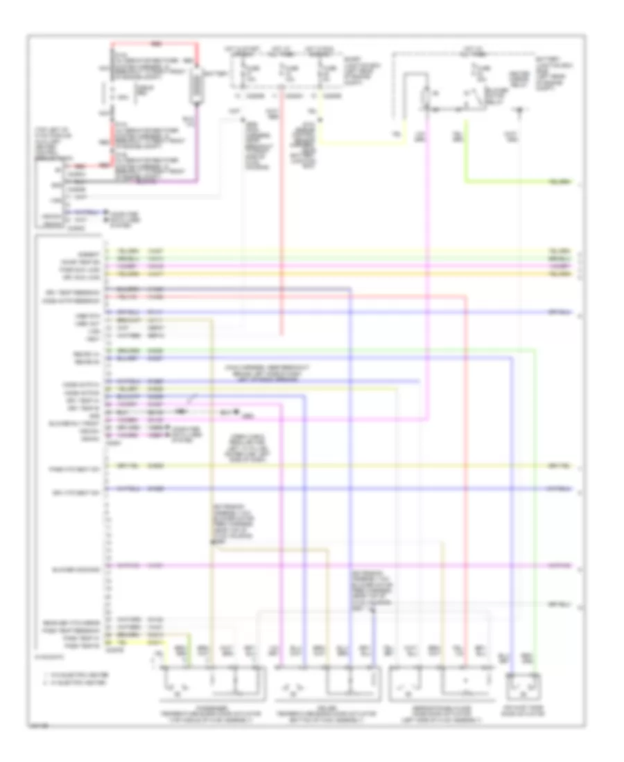
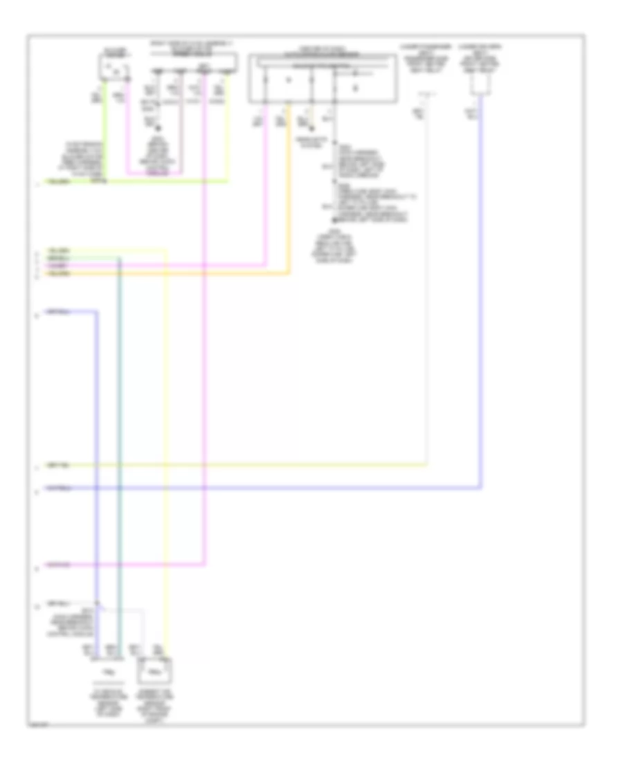
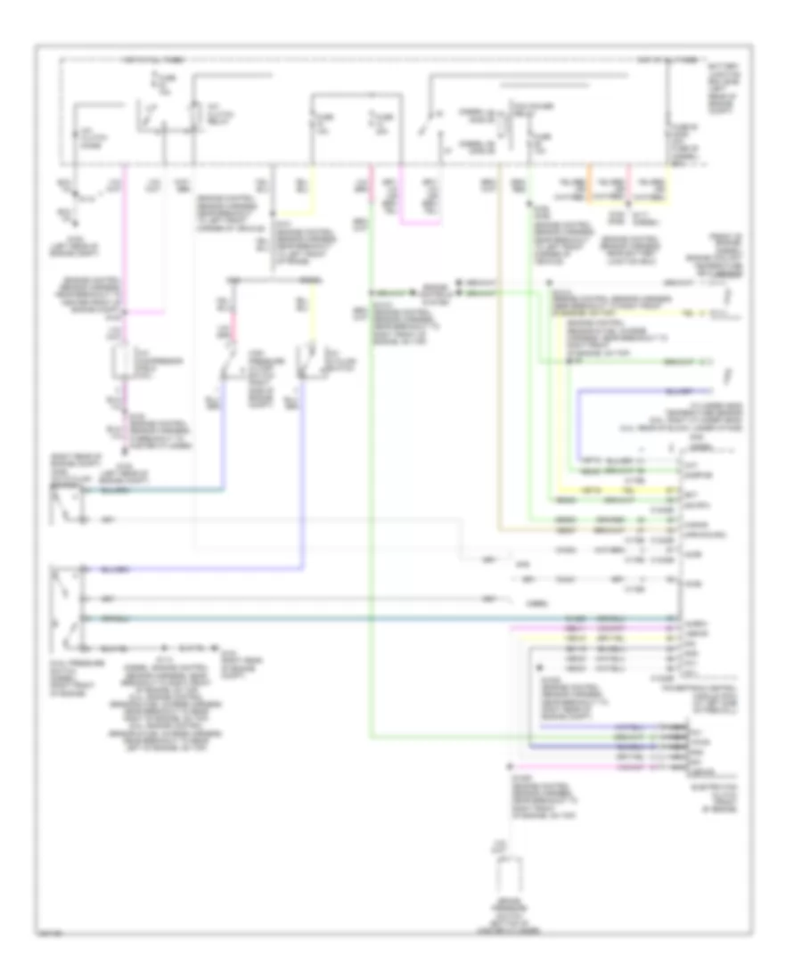
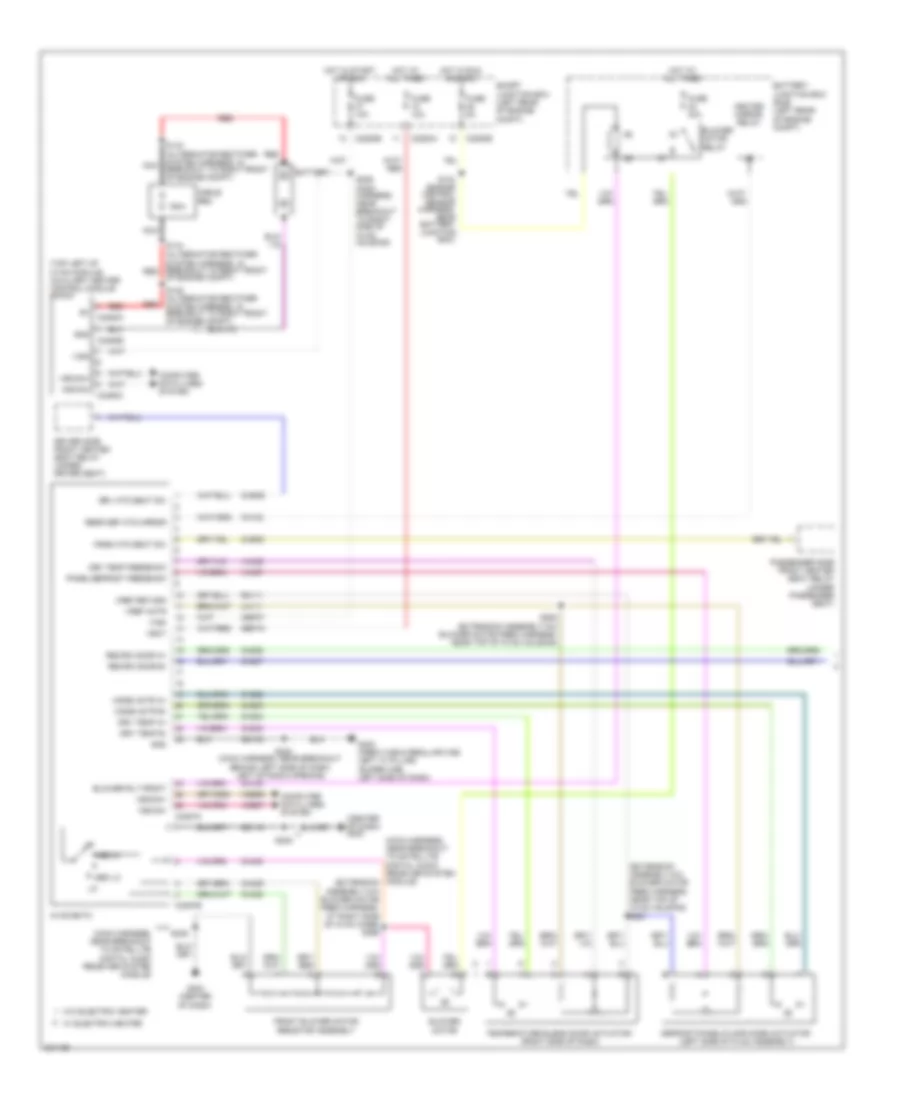
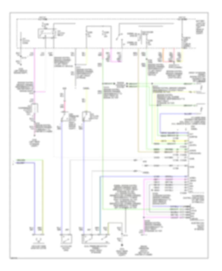
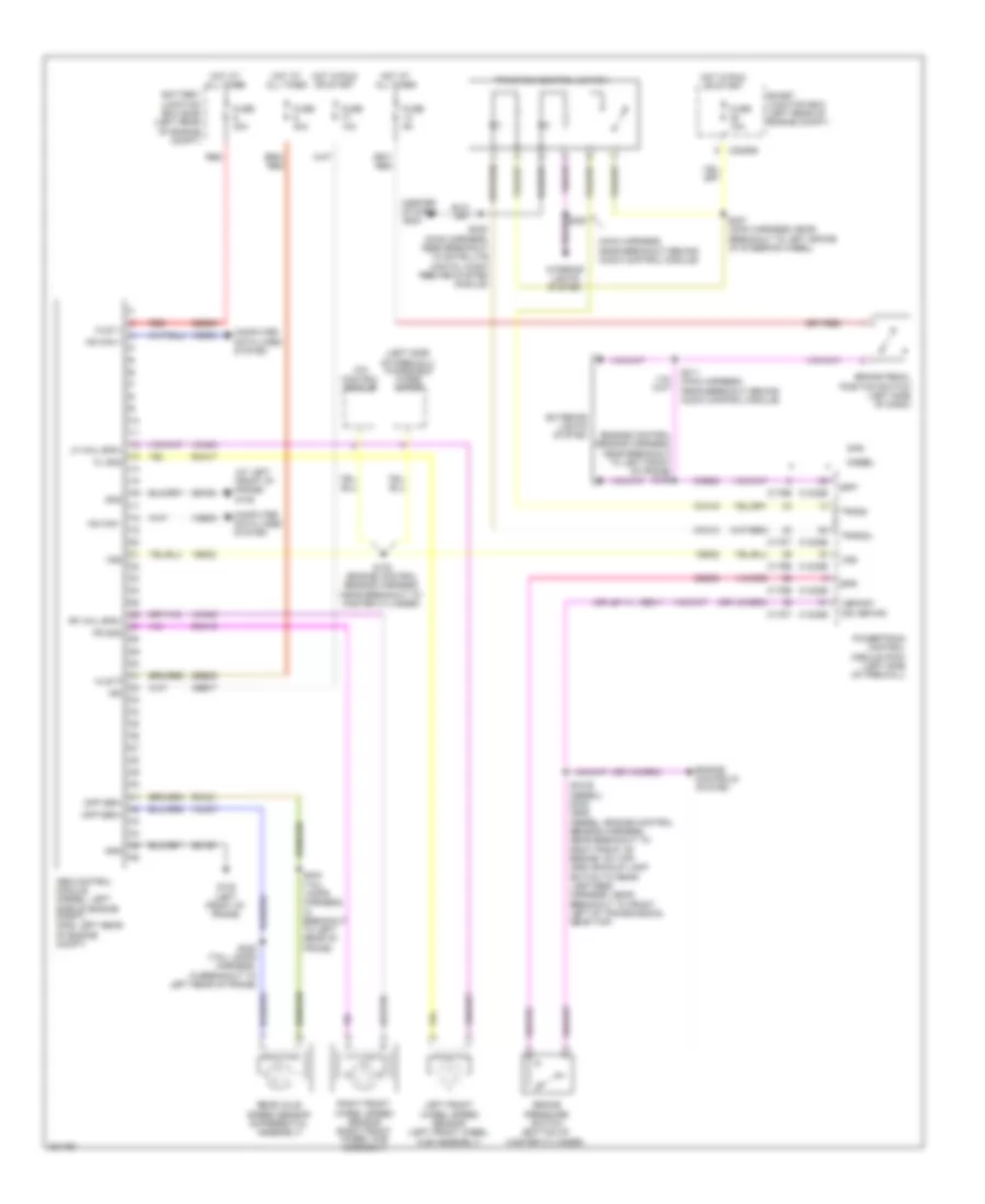
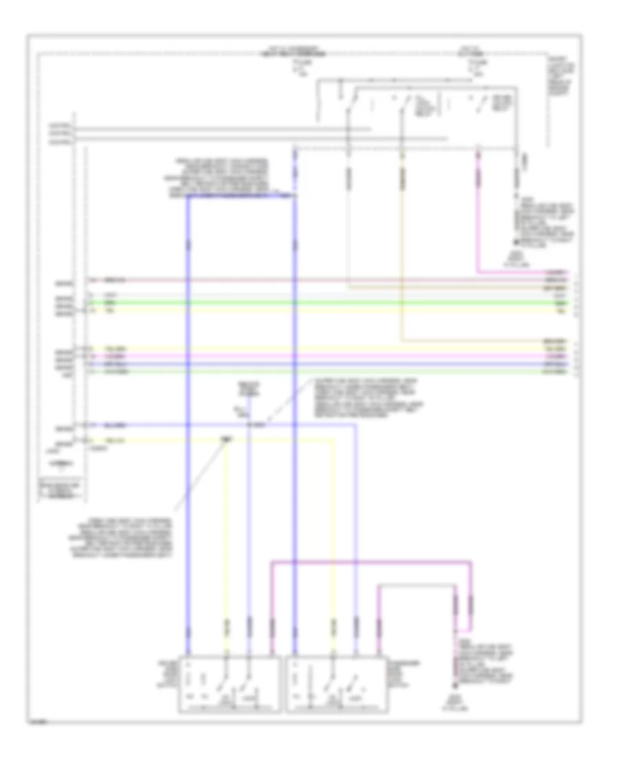
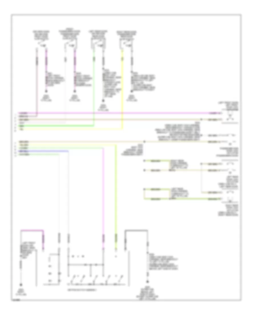
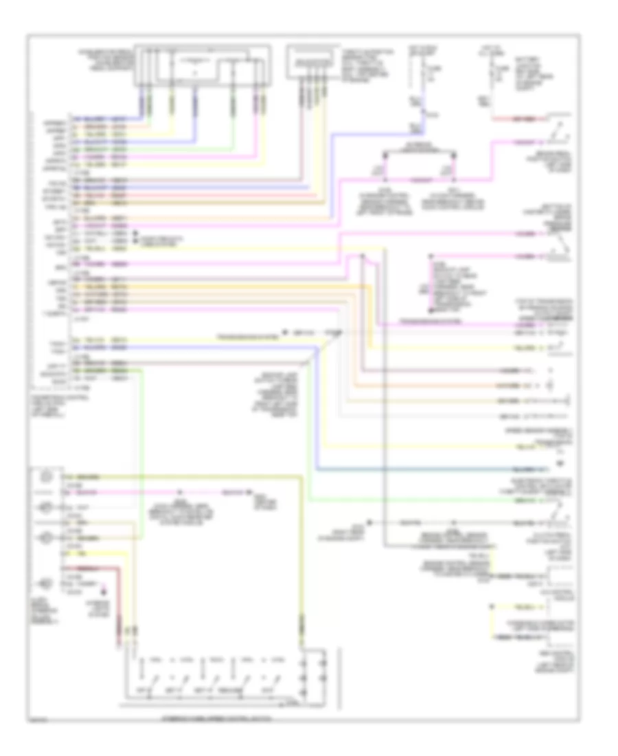
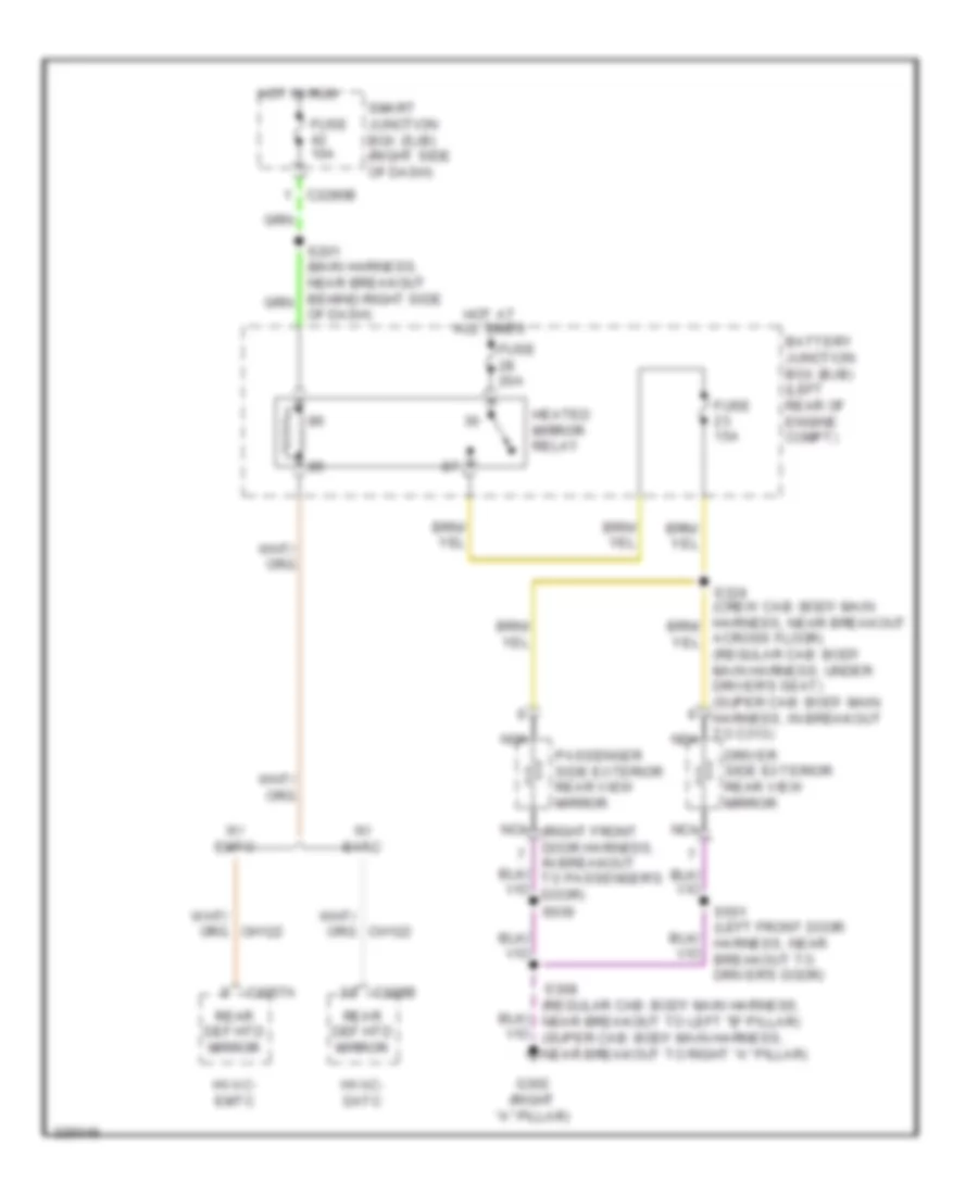
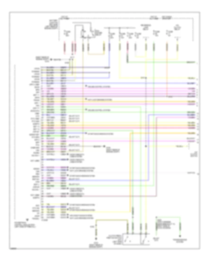
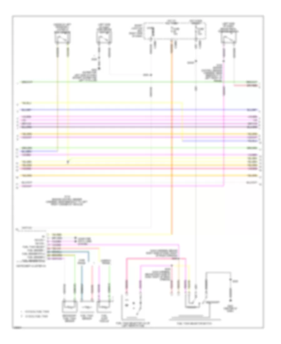
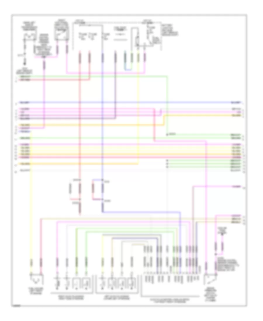
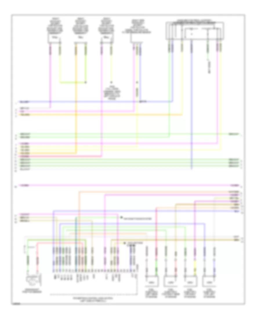
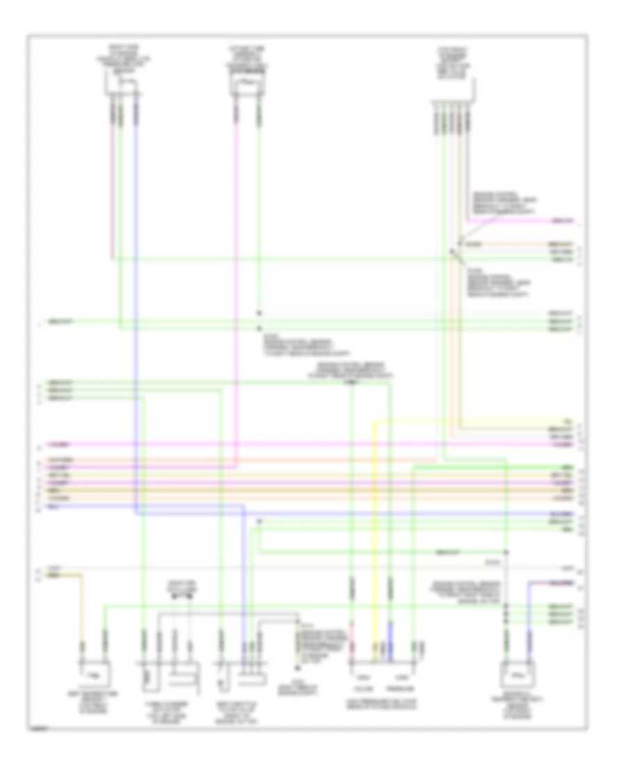
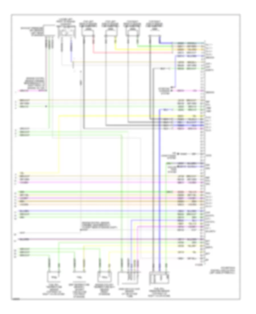
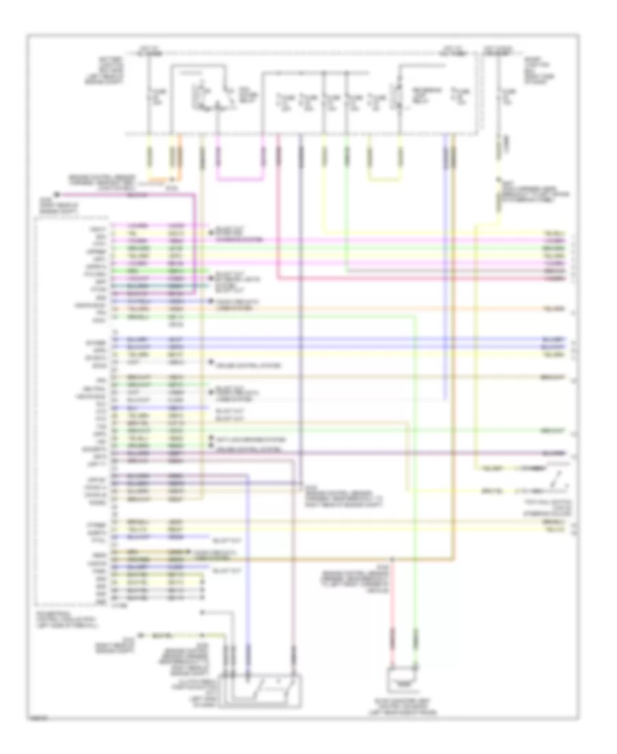
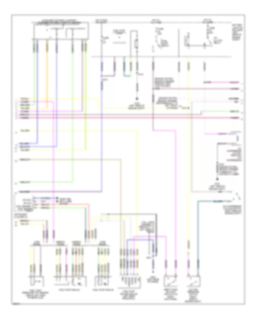
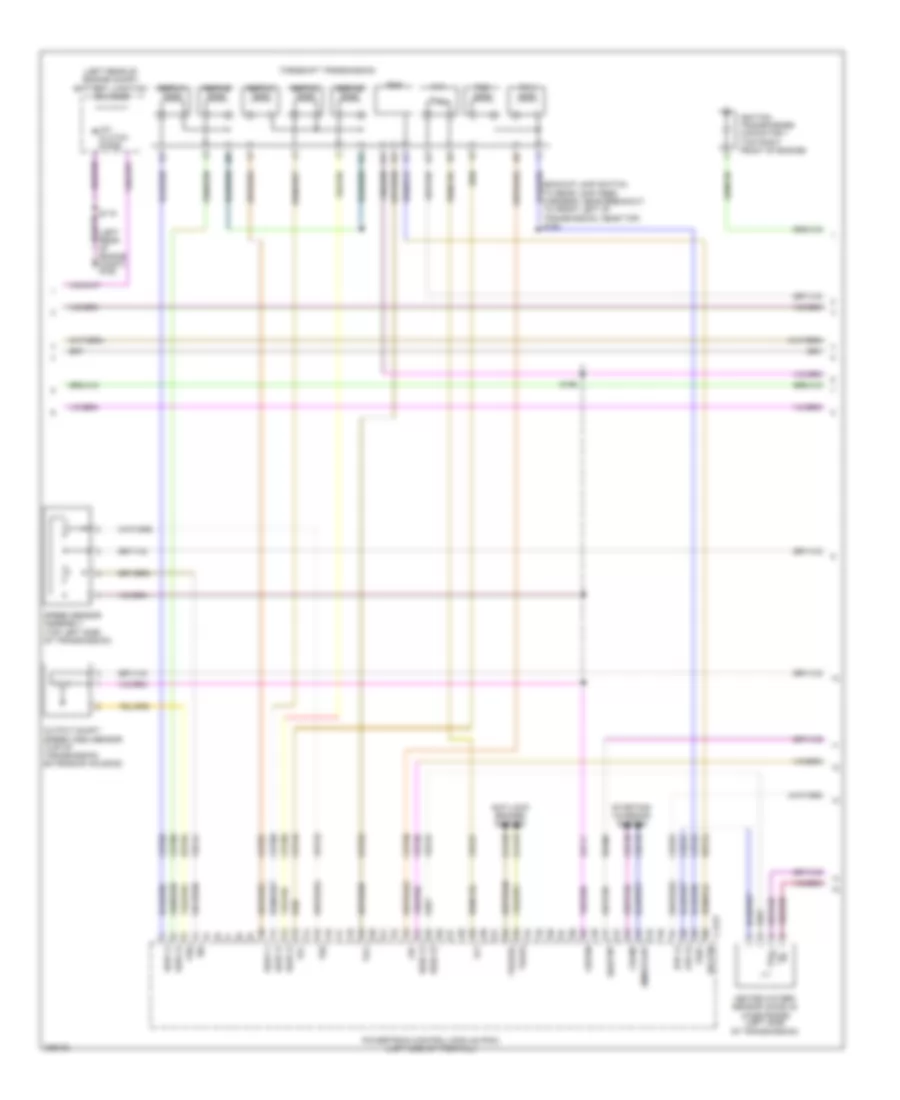
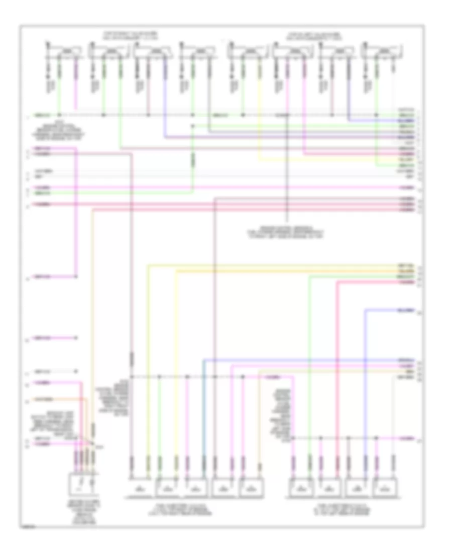
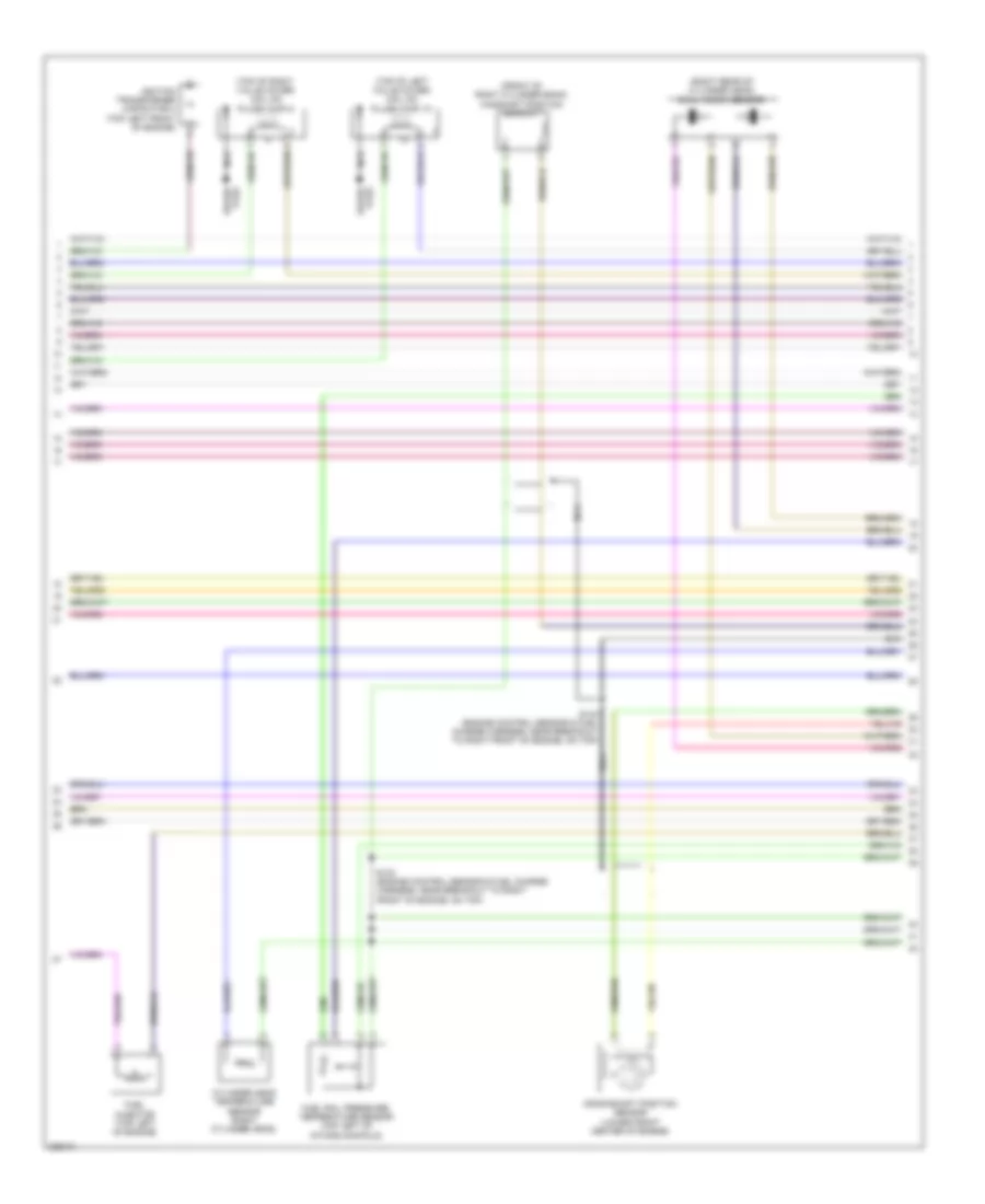
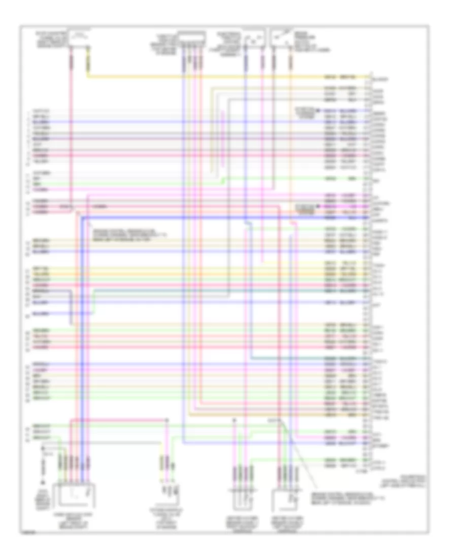
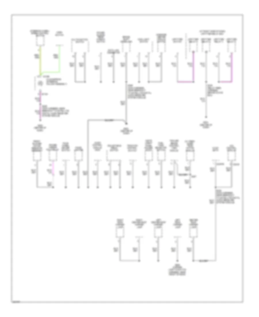
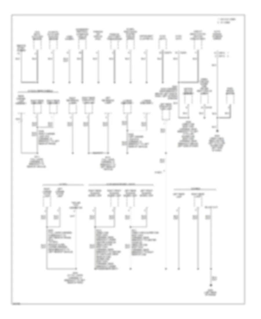
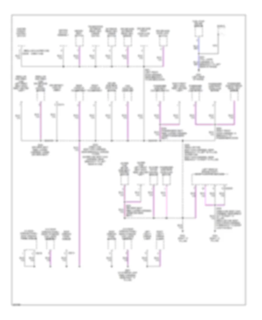
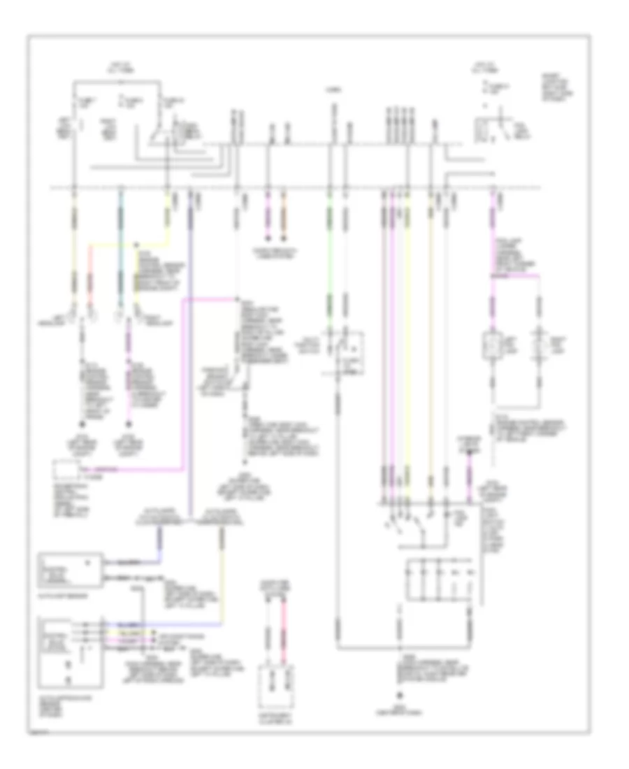
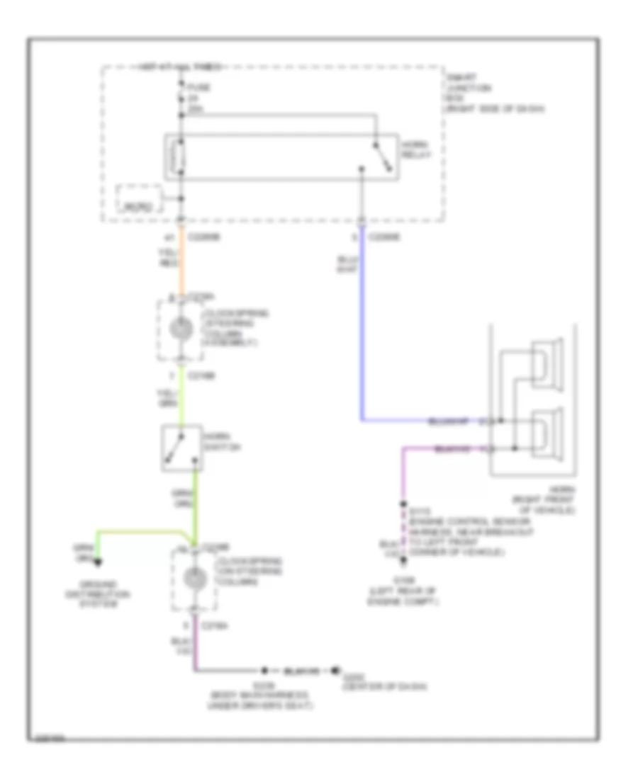
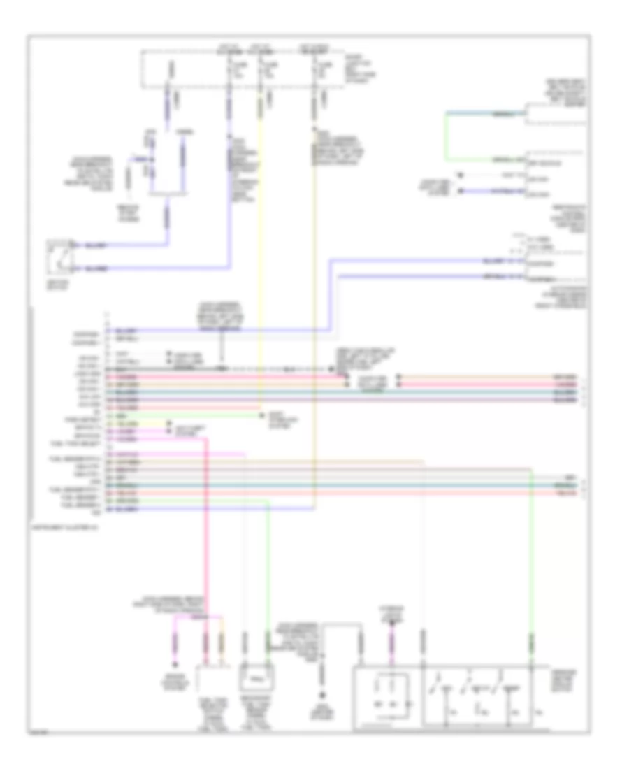
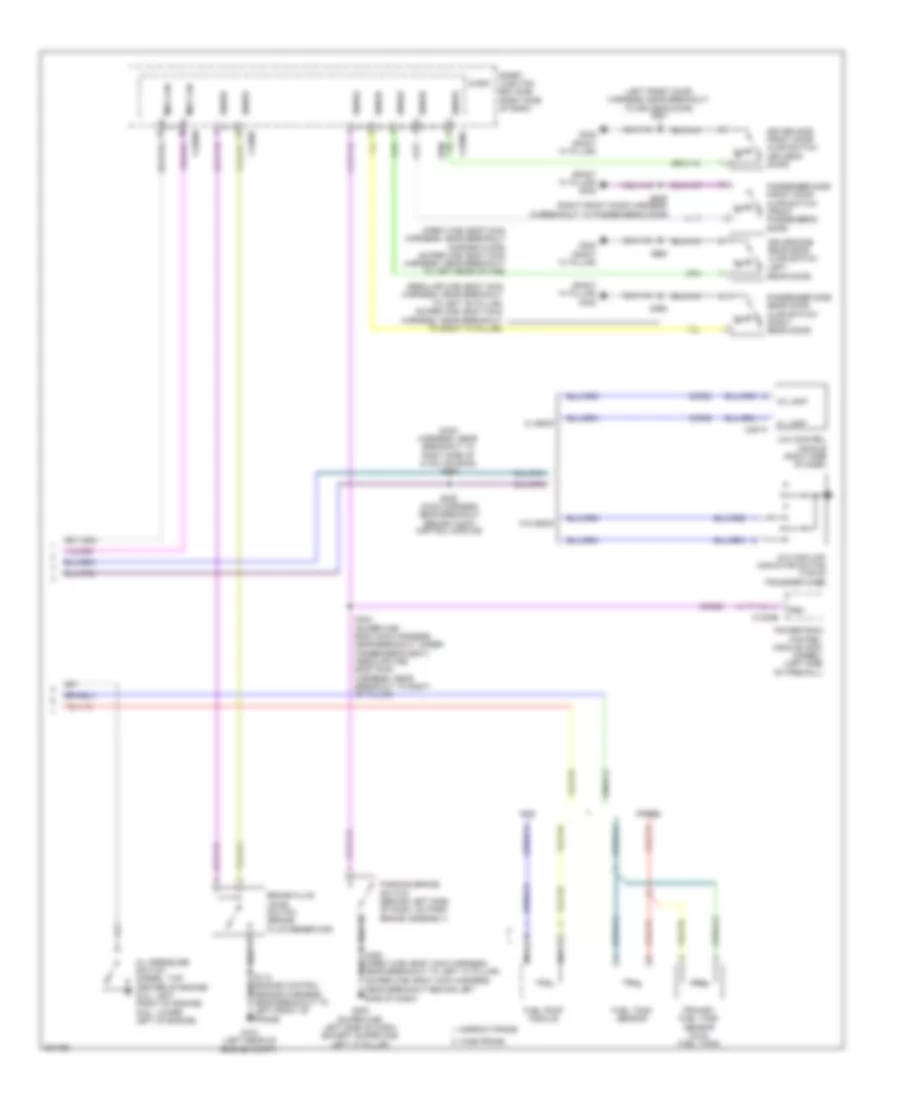
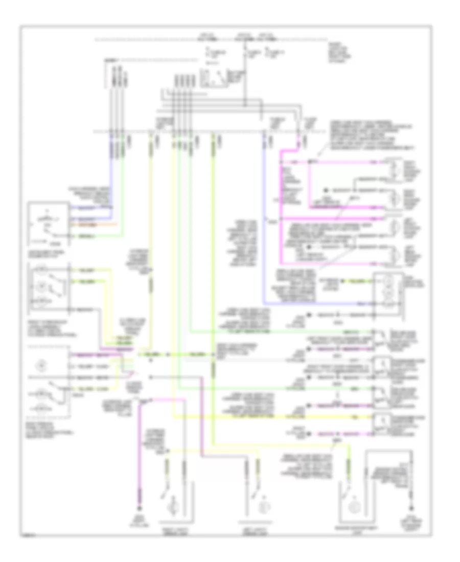
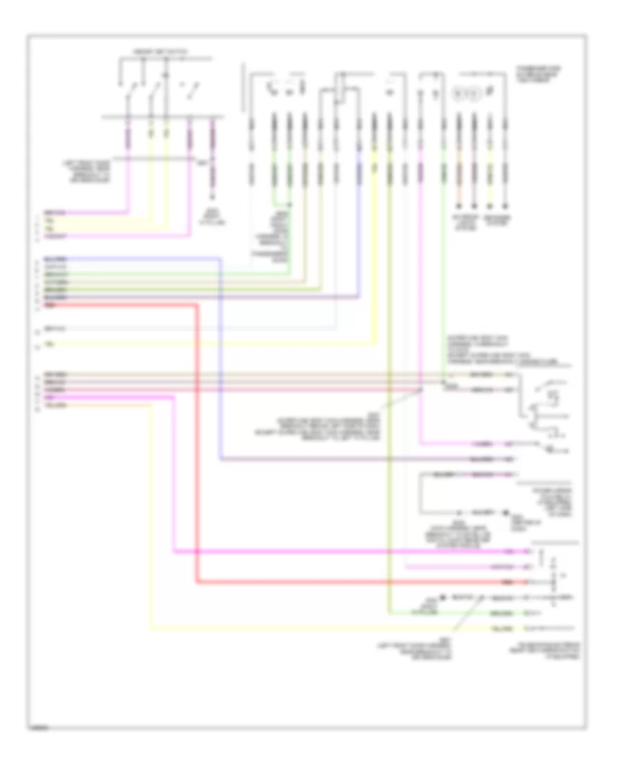
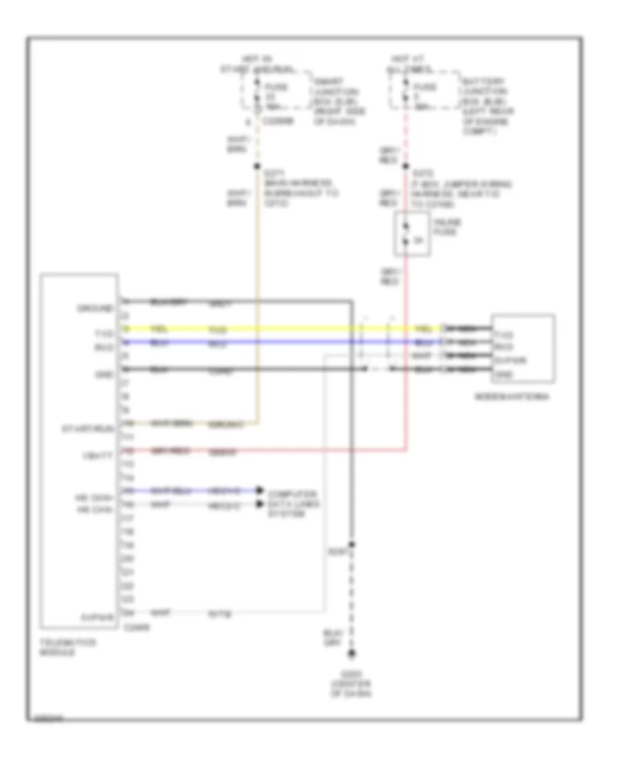
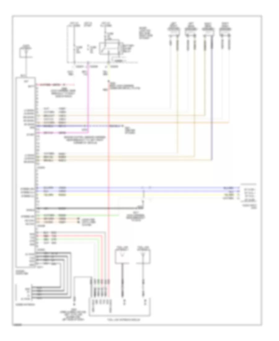
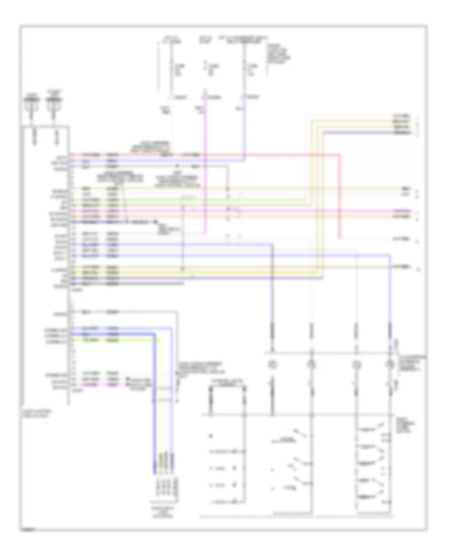
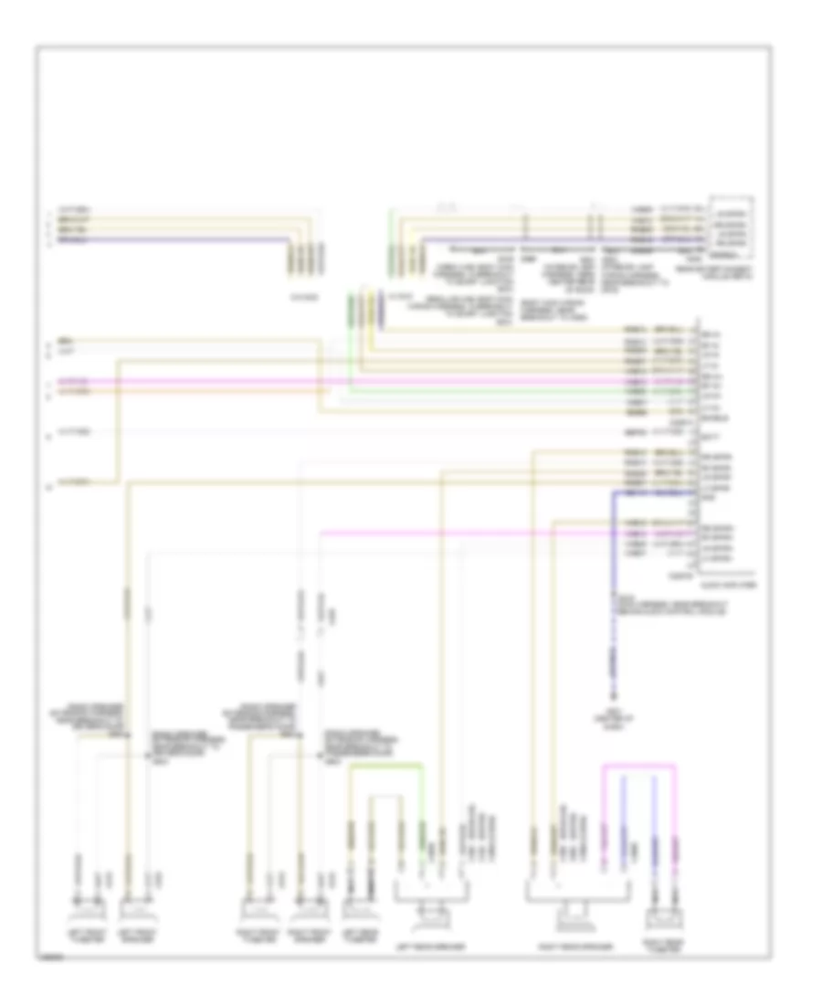
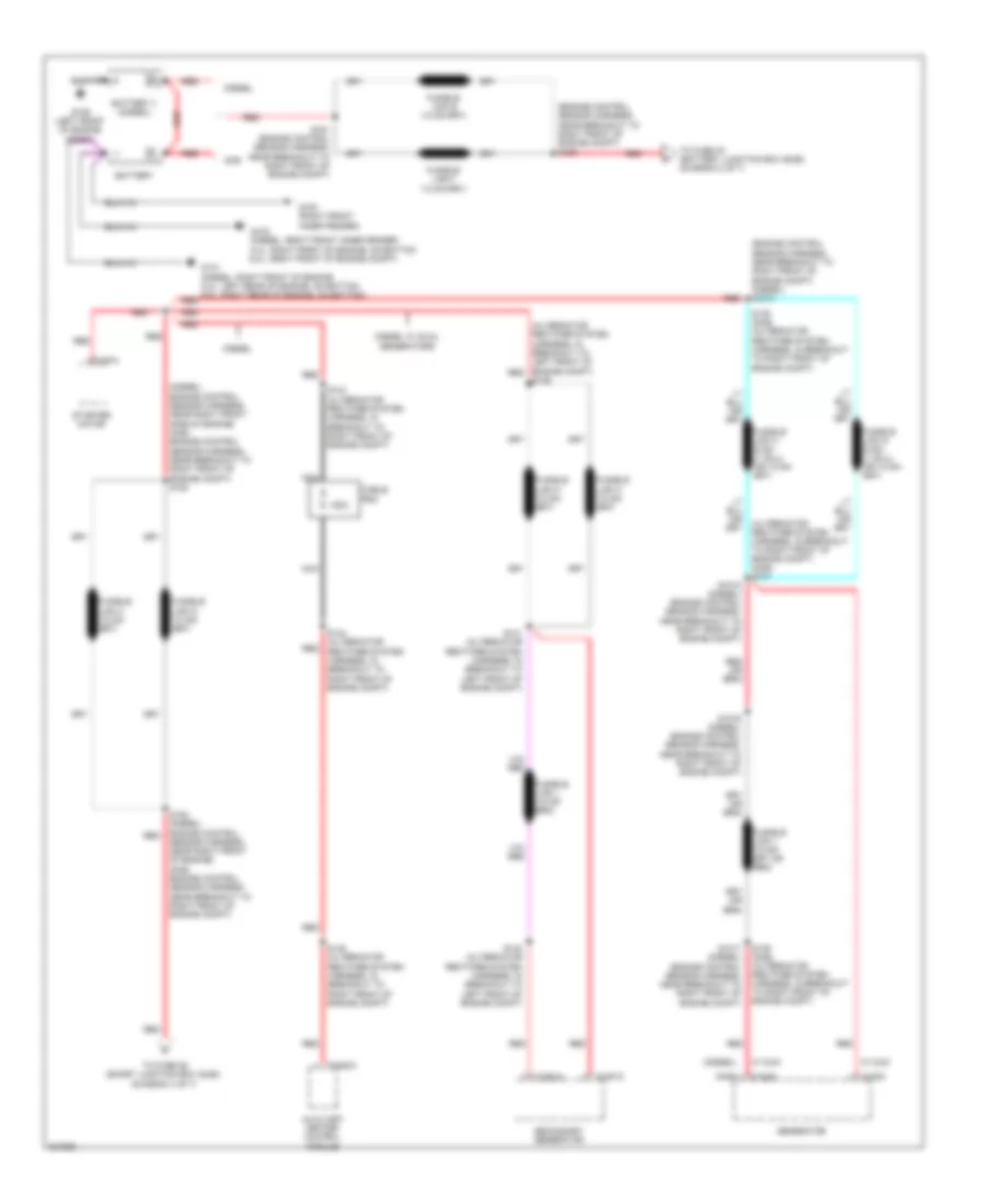
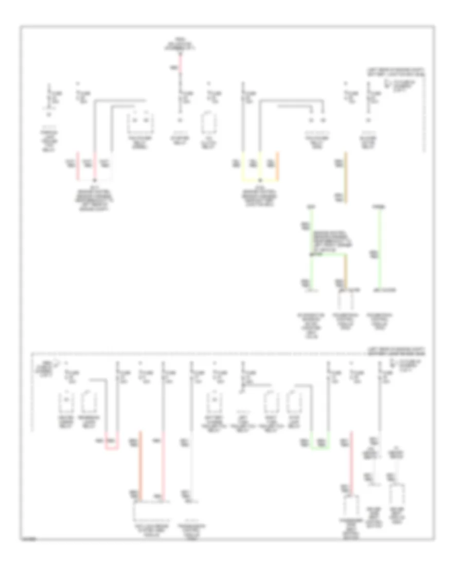
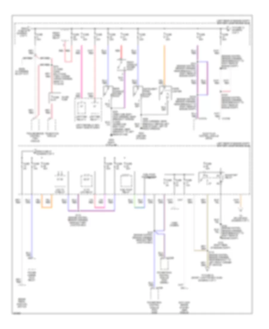
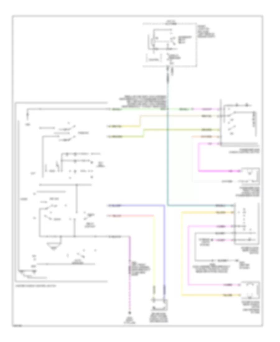
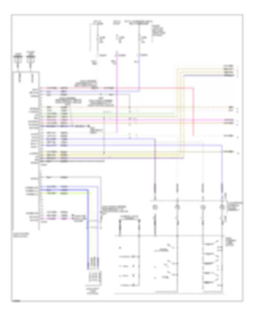
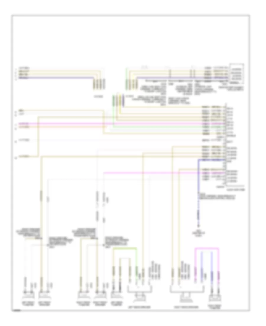
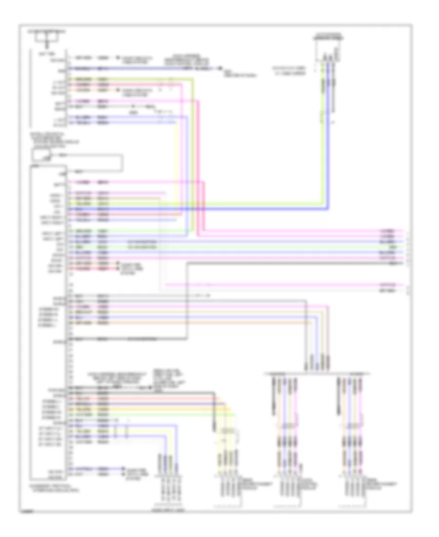
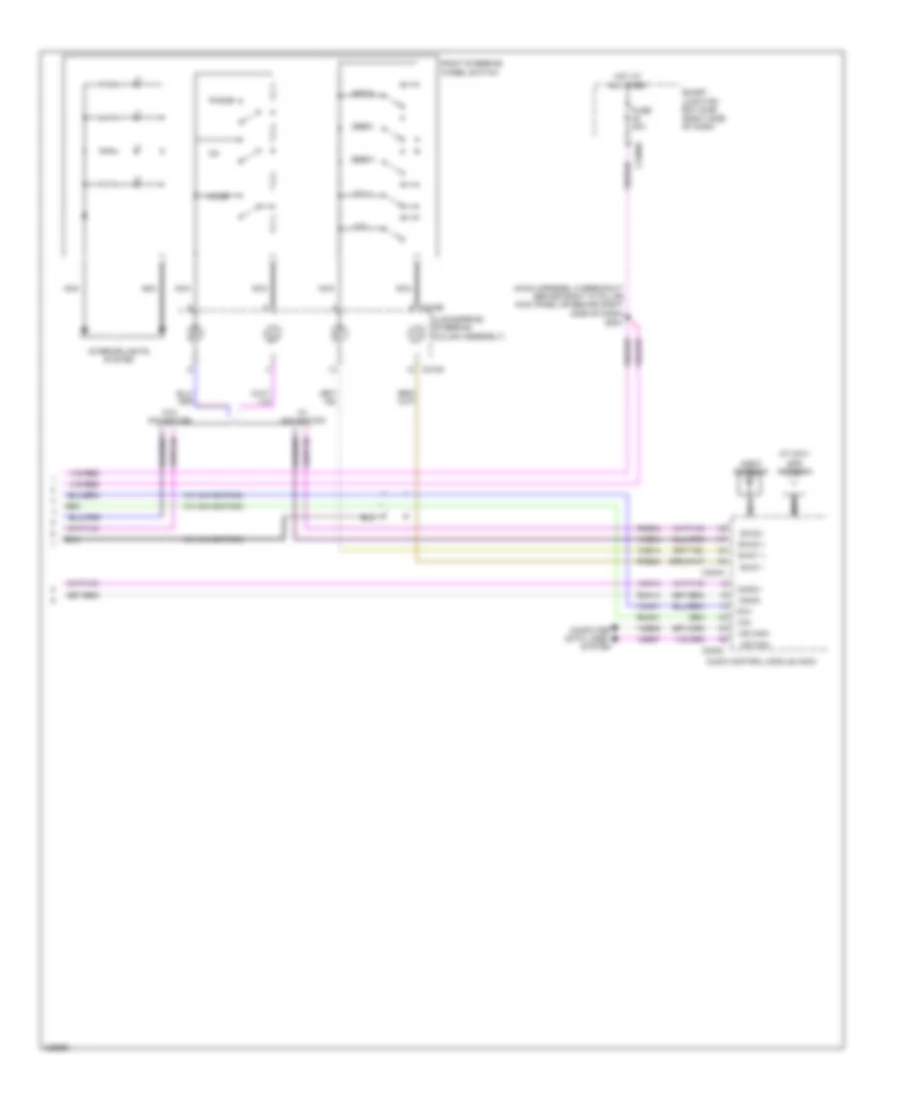
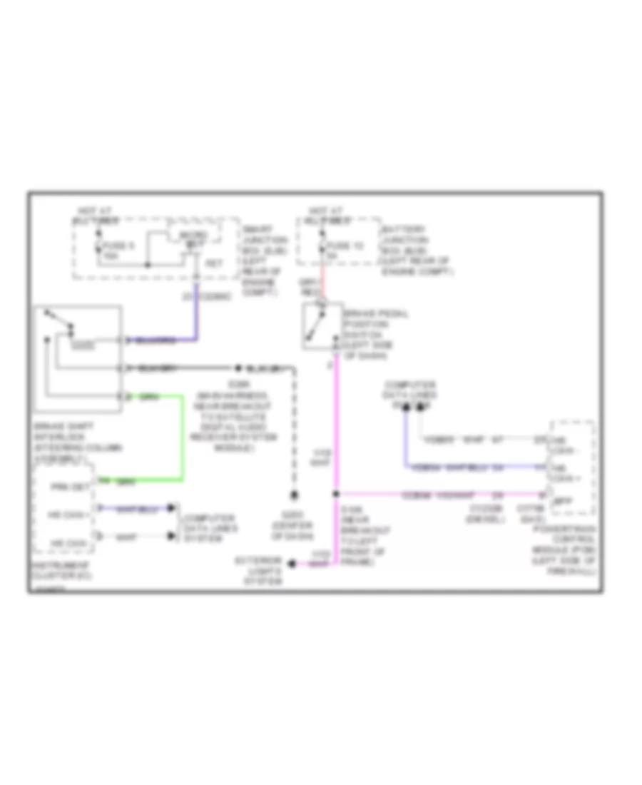
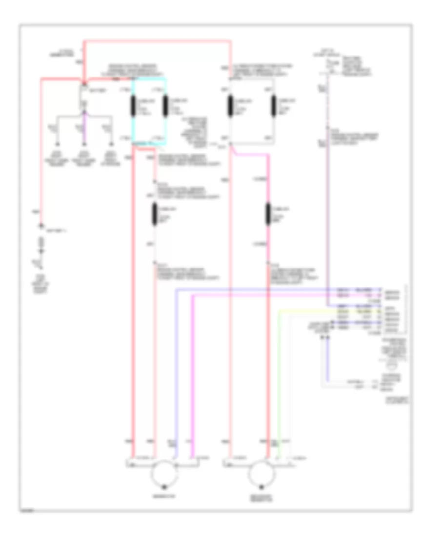
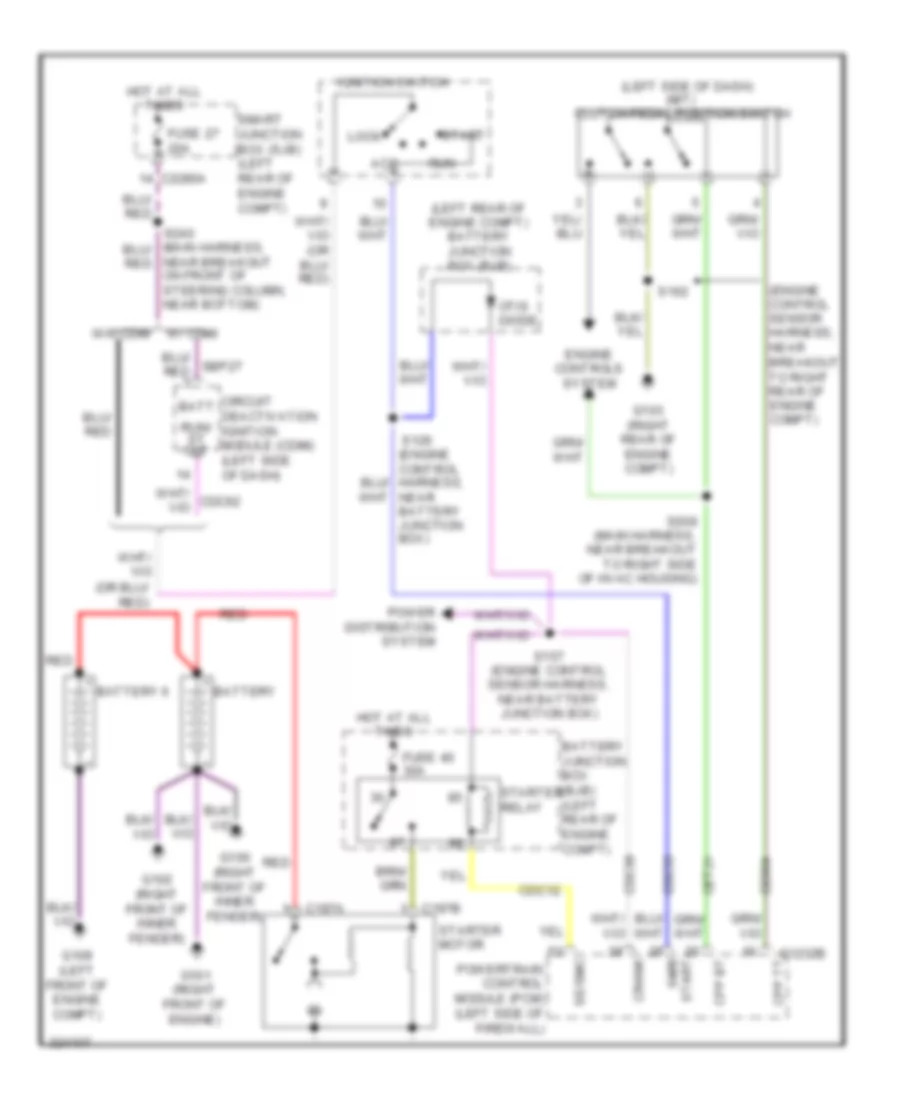
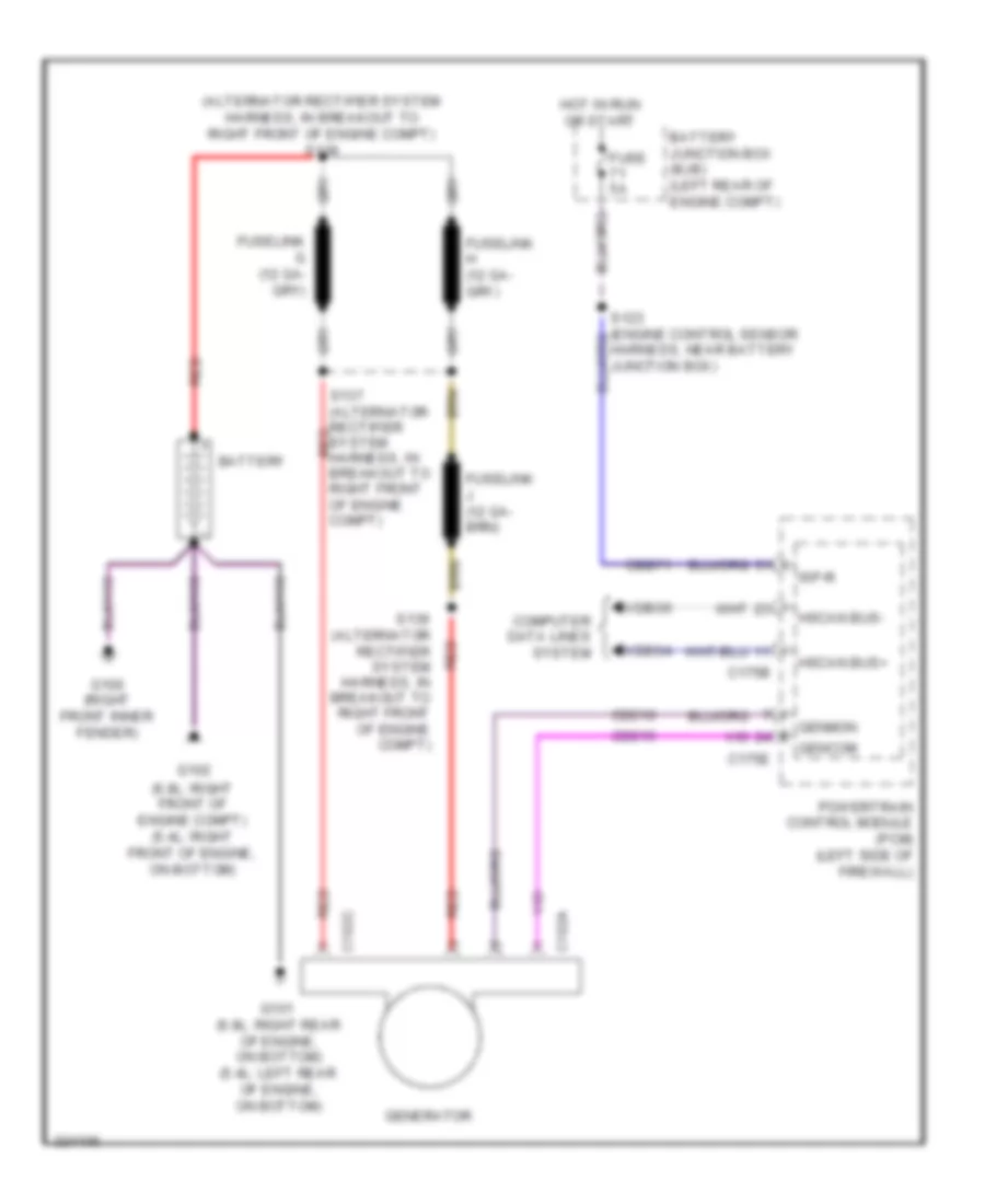
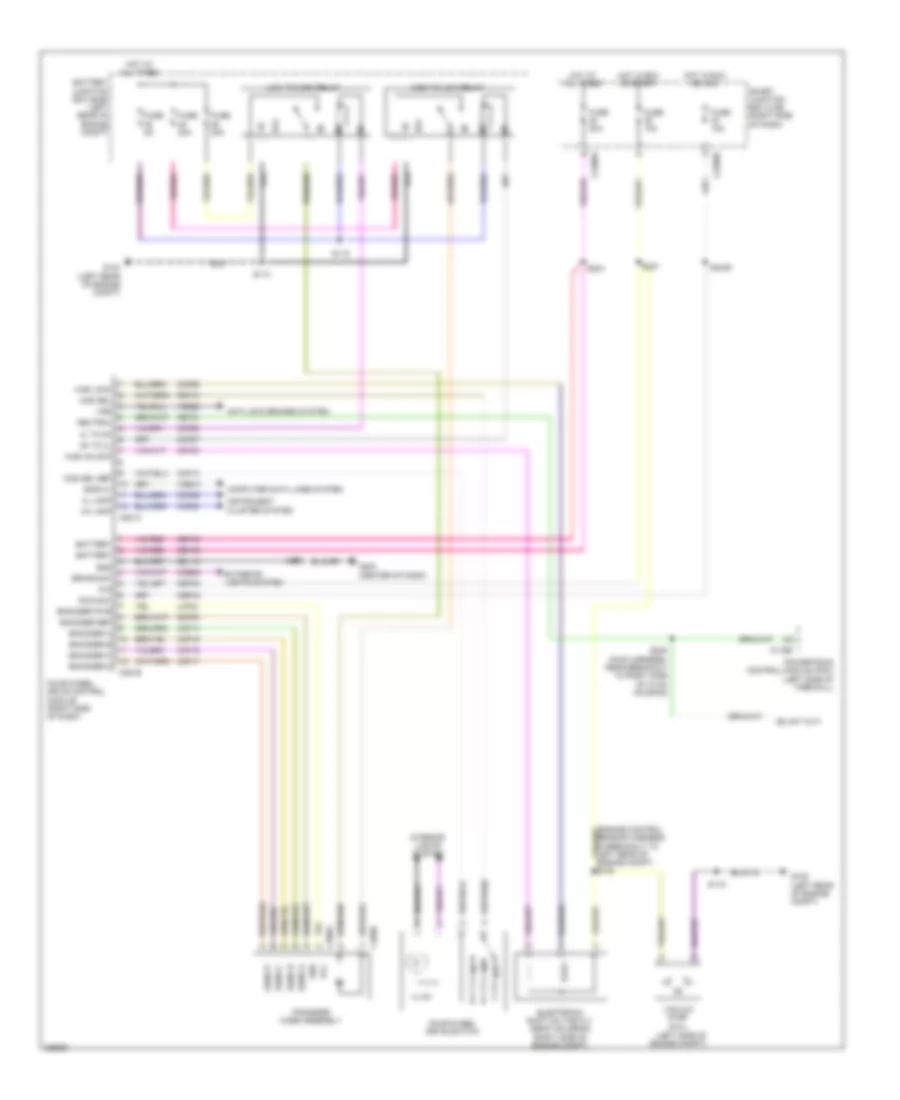
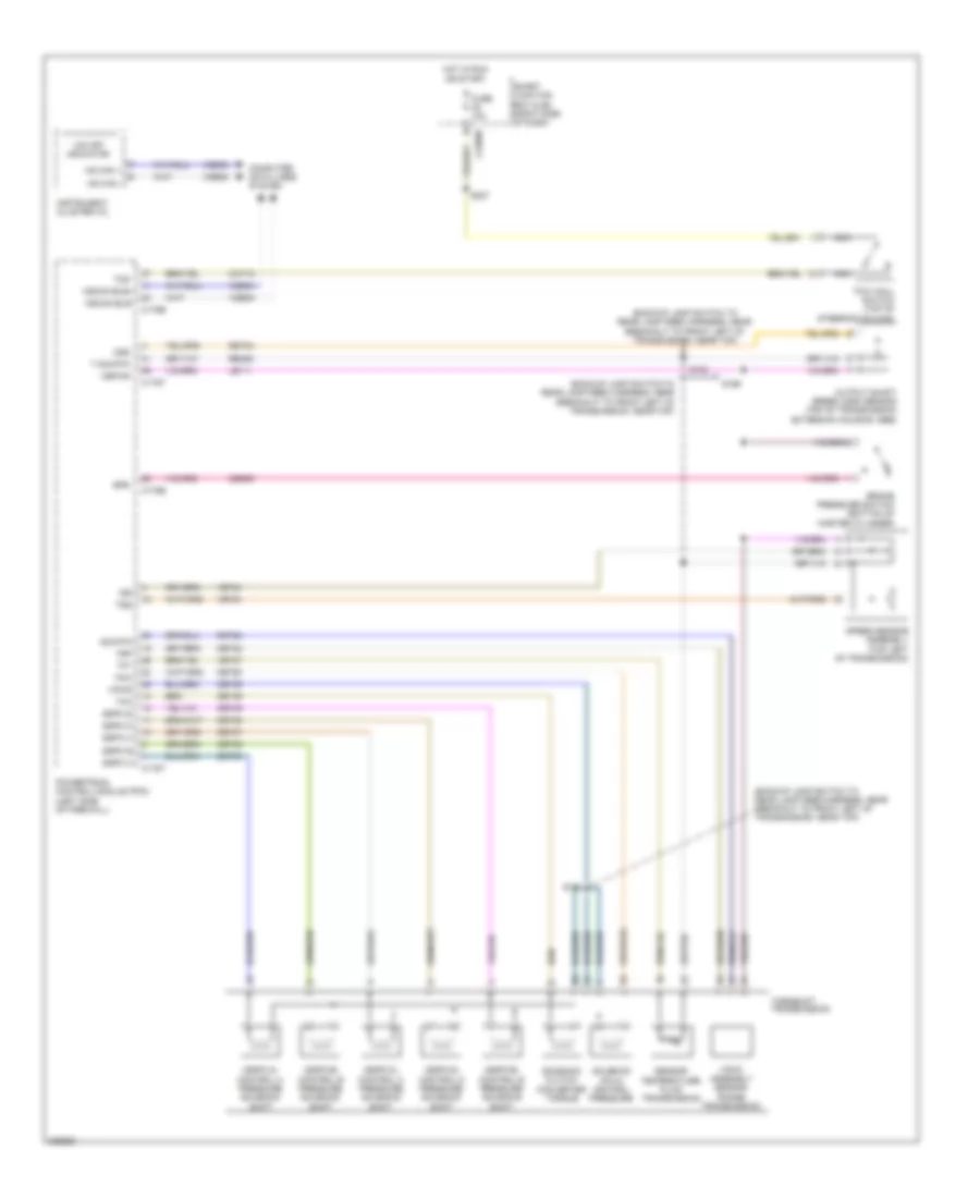
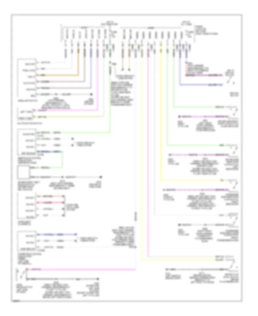
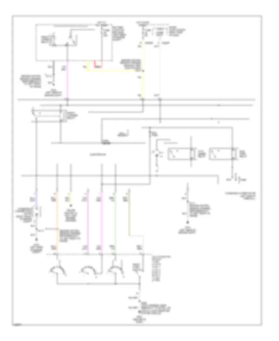
List of elements for Automatic A/C Wiring Diagram (3 of 3) for Ford F550 Super Duty 2010:
78
(diesel)
(diesel) (gas)
(diesel) engine coolant temperature (ect) sensor
(diesel: engine control sensor harness, near breakout to right front of engine, on top) (5.4l: engine control sensor & fuel charge harness, near breakout to rear right of engine, on top) (6.8l: engine control sensor & fuel charge harness, near breakout to rear left of engine, on top)
(engine control sensor & fuel charge harness, near breakout to right front of engine, on top) s133
(engine control sensor harness, near battery junction box)
(engine control sensor harness, near breakout to center front of engine compt)
(engine control sensor harness, near breakout to left front corner of vehicle)
(front of engine)
(gas)
(right rear of engine compt) (gas) a/c cycling switch
A/c clutch diode
A/c clutch relay
A/c compressor field coil
A/c cycling switch
Accr
Accs
Acpsw
Battery junction box (bjb) (left rear of engine compt)
Brake pressure switch (bottom of master cylinder)
C1232b
C1232e
C175b
C175e
Ce237
Cec11
Ch302
Ch421
Ch425
Cht
Cylinder head temperature sensor (6.8l: right cylinder head) (5.4l: rear of block, under intake)
Diesel
Dual pressure switch (diesel) (right front of engine)
Ect
Electric fan clutch (front of engine)
Engine controls system
Fcv
Fuse 10a
Fuse 20a
Fuse 50 (gas) 30a fuse 39 (diesel) 50a
G103 (right rear of engine compt)
G108 (left rear of engine compt)
Gas
Gd119
Gnd
High pressure cutoff switch (right side of engine compt)
Hot at all times
Kapwr
Mpr (pcm-rc)
Nca fcv
Nca gnd
Nca sig
Nca vbpwr
Nca vpwr
Near breakout to left front of frame)
Pcm power relay
Powertrain control module (pcm) (at left side of firewall)
Re405
S1008 (engine control sensor harness, near breakout to right rear of engine compt)
S1009 (engine control sensor harness, near breakout to right front of engine, on top)
S1010 (engine control sensor harness, near breakout to right front of engine, on top)
S1013 (engine control sensor harness, near breakout to right front of engine, on top)
S114
S115
S117 (diesel)
S120
S128 (engine control sensor harness, in breakout to master cylinder)
S154 (gas)
S158 (gas)
Sbb36
Sig
Sig rtn
Sigrtne
Vbpwr
Ve712
Ve716
Vec03
Vec10
Manual A/C Wiring Diagram (1 of 2) for Ford F550 Super Duty 2010
List of elements for Manual A/C Wiring Diagram (1 of 2) for Ford F550 Super Duty 2010:
98
(center of dash) g203
(engine control sensor harness, near battery junction box)
(extension assembly-a/c blower motor feed harness, near top of hvac housing) s251
(main harness, near breakout to right side of hvac housing)
(main harness, near breakout to satellite digital audio receiver system module)
(main harness, near breakout to satellite digital audio receiver system module) (extension assembly-a/c blower motor feed harness, at right side of hvac case) s256
(top left of hvac module) auxiliary heater control module (ahcm)
150a
Battery
Battery junction box (bjb) (left rear of engine compt)
Blower motor
Blower motor relay
Blower rly front
Breakout to right front of engine compt)
C2280a
C2280b
C2280e
C2357a
C2357b
C2463a
C2463b
C2463c
Cable pro
Cbp37
Ch122
Ch123
Ch202
Ch203
Ch207
Ch208
Ch233
Ch234
Ch428
Ch429
Ch430
Chs29
Chs30
Computer data lines system
Defrost/panel/floor mode actuator (left side of hvac assembly)
Driver side front heated seat relay (under driver seat)
Drv htd seat sw
Drv temp a+
Drv temp b-
Drv temp feedback
Front blower motor resistor assembly
Fuse 10a
Fuse 40a
Fuse 5a
G203 (center of dash)
G300 (crew cab & regular cab: left "a" pillar) (super cab: left side of dash)
Gd115
Gd133
Gnd
Heated mirror relay
Hot at all times
Hot in run and acc
Hot in start or run
Hscan+
Hscan-
Hvac-emtc
Lh111
Med hi
Med lo
Mode actr a+
Mode actr b-
Mscan+
Mscan-
Nca
Of engine compt)
Panel/defrost feedback
Pass htd seat sw
Passenger side front heated seat relay (under passenger seat)
Rear def htd mirror
Recirc door a+
Recirc door b-
Red
Rh111
S104
S143 (alternator rectifier system harness, in nca
S144 (alternator rectifier system harness, in breakout to right front red
S145 (alternator rectifier system harness, in breakout to right front of engine compt)
S206
S224 (main harness, near breakout behind left side of dash, left of radio opening)
S235
S250 (extension assembly-a/c blower motor feed harness, near top of hvac housing)
Sbp15
Smart junction box (left rear of engine compt)
Temperature blend door actuator (right side of dash)
Vbat
Vdb06
Vdb07
Vh437
Vh439
Vign
Vref actr
Vref return
W/ electric heater
W/o electric heater
Manual A/C Wiring Diagram (2 of 2) for Ford F550 Super Duty 2010
List of elements for Manual A/C Wiring Diagram (2 of 2) for Ford F550 Super Duty 2010:
78
(diesel)
(diesel) (gas)
(diesel: engine control sensor harness, near breakout to right front of engine, on top) (5.4l: engine control sensor & fuel charge harness, near breakout to rear right of engine, on top) (6.8l: engine control sensor & fuel charge harness, near breakout to rear left of engine, on top)
(engine control sensor & fuel charge harness, near breakout to right front of engine, on top) s133
(engine control sensor harness, near battery junction box)
(engine control sensor harness, near breakout to center front of engine compt)
(engine control sensor harness, near breakout to left front corner of vehicle)
(engine control sensor harness, near breakout to right front of engine, on top)
(front of engine) (diesel) engine coolant temperature (ect) sensor
(gas)
A/c clutch diode
A/c clutch relay
A/c compressor clutch field coil
A/c cycling switch
A/c cycling switch (gas)
Accr
Accs
Acpsw
Air inlet mode door actuator
Battery junction box (bjb) (left rear of engine compt)
Brake pressure switch (bottom of master cylinder)
C1232b
C1232e
C175b
C175e
Ce237
Cec11
Ch302
Ch421
Ch425
Cht
Cylinder head temperature sensor (6.8l: right cylinder head) (5.4l: rear of block, under intake)
Diesel
Dual pressure switch (diesel) (right front of engine)
Ect
Electric fan clutch (front of engine)
Engine controls system
Fcv
Fuse 10a
Fuse 20a
Fuse 50 (gas) 30a fuse 39 (diesel) 50a
G103 (right rear of engine compt)
G108 (left rear of engine compt)
Gas
Gd119
Gnd
High pressure cutoff switch (right side of engine compt)
Hot at all times
Kapwr
Mpr (pcm-rc)
Nca fcv
Nca gnd
Nca sig
Nca vbpwr
Nca vpwr
Near breakout to left front of frame)
Pcm power relay
Powertrain control module (pcm) (at left side of firewall)
Re405
Red
S1008 (in engine control sensor harness, near breakout to right rear of engine compt)
S1010
S1013 (engine control sensor harness, near breakout to right front of engine, on top)
S114
S115
S120
S128 (engine control sensor harness, in breakout to master cylinder)
S154 s117 (diesel)
S158 (gas)
Sbb36
Sig
Sig rtn
Sigrtne
Vbpwr
Ve712
Ve716
Vec03
Vec10
ANTI-LOCK BRAKES
Anti-lock Brakes Wiring Diagram for Ford F550 Super Duty 2010
List of elements for Anti-lock Brakes Wiring Diagram for Ford F550 Super Duty 2010:
80
(at left front of frame) g135
(center of dash) g203
(engine control sensor harness, near breakout to left front of frame) s106
(left side of firewall) windshield wiper motor
(main harness, near breakout behind audio control module)
(main harness, near breakout to satellite digital audio reeiver system module)
(or le111)
4x4 control module
Abs control module (diesel: left side of engine compt) (gas: left rear of engine compt)
Battery junction box (bjb) (left rear of engine compt)
Bpp
Bps
Brake pedal position switch (left side of dash)
Brake pressure switch (bottom of master cylinder)
C1232b
C1232e
C175b
C175e
C175t
C2280b
Cbb77
Cca10
Cca15
Ccb08
Cec11
Ces09
Computer data lines system
Diesel
Diff sen+
Diff sen-
Engine controls system
Exterior lights system
Fl gnd
Fr gnd
Fuse 10a
Fuse 40a
Fuse 5a
G135 (left front of frame)
Gas
Gd163
Gnd
Hot at all times
Hot in run or start
Hs can +
Hs can -
Ign
Interior lights system
Kl30 p
Kl30 v
Left front wheel speed sensor (left front wheel hub assembly)
Lf whl spd+
Powertrain control module (pcm) (left side of firewall)
Rca17
Rca19
Rca21
Rear axle speed sensor (differential assembly)
Red
Rf whl spd+
Right front wheel speed sensor (right front wheel hub assembly)
S1009 (diesel) s196 (gas) (diesel: engine control sensor harness, near breakout to right front of engine, on top) (gas: backup lamp switch to rear lamp feed harness, near breakout to front left of transmission, near top)
S130 (engine control sensor harness, near breakout to master cylinder)
S211 (main harness, near breakout behind audio control module)
S227 (main harness, near breakout to left spoke of steering wheel)
S235
S404 (tail lamps harness, in breakout to left rear of frame)
S405 (tail lamps harness, in breakout to left rear of frame)
Sbb06
Sbb09
Smart junction box (left rear of engine compt)
Tracs
Tracsil
Traction control switch
Vbpwrt (or vbpwr)
Vca03
Vca05
Vca07
Vdb04
Vdb05
Ve822
Vss
ANTI-THEFT
Forced Entry Wiring Diagram (1 of 2) for Ford F550 Super Duty 2010
List of elements for Forced Entry Wiring Diagram (1 of 2) for Ford F550 Super Duty 2010:
30
(crew cab: body main harness, near breakout to right "a" pillar) (regular cab: body main harness, near breakout to passenger safety belt retractor pretensioner) (super cab: body main harness, near breakout under passenger's seat)
(regular cab: body main harness, near breakout across floor) (super cab: body main harness, near breakout to passenger safety belt retractor pretensioner) (crew cab: body main harness, near breakout under passenger's seat)
(super cab: body main harness, near breakout under passenger's seat) (crew cab: body main harness, near breakout to right "b" pillar) (regular cab: body main harness, near breakout to passenger safety belt retractor pretensioner)
All lock/ unlock relay
Antenna
Breakout to left "b" pillar) (super cab: body main harness, near breakout to right "a" pillar)
Breakout to right
C2280c
C2280d
Control
Driver side door lock switch
Driver unlock relay
Fuse 15a
Fuse 20a
G302 (right "a" pillar)
Hot at all times
Hot w/ accessory delay relay energized
Hsd
Lock
Logic
Passenger side door lock switch
Remote start access
Rke receiver internal antenna
S301
S305
S306
S308
Sense
Smart junction box (sjb) (left rear of engine compt)
Un lock
Forced Entry Wiring Diagram (2 of 2) for Ford F550 Super Duty 2010
List of elements for Forced Entry Wiring Diagram (2 of 2) for Ford F550 Super Duty 2010:
26
(crew cab only)
(driver's door) driver side front door ajar switch
(front passenger's door) passenger side front door ajar switch
(left front door) left front door lock actuator
(left rear door harness, in breakout to left "b" pillar) s800
(left rear door)
(left rear door) driver side rear door ajar switch
(right rear door harness, in breakout to left "b" pillar) s700
(right rear door)
(right rear door) passenger side rear door ajar switch
1/2
3/4
5/6
7/8
9/0
Ajar
G300 (super cab: behind left side of dash) (except super cab: left "a" pillar)
G302 (right "a" pillar)
Keypad switch assembly
Left rear door lock actuator
Passenger side door lock actuator (passenger's door)
Right rear door lock actuator
S302 (crew cab: body main harness, near breakout across floor) (regular cab: body main harness, near breakout to passenger safety belt retractor pretensioner) (super cab: body main harness, near breakout under passenger's seat)
S308 (regular cab: body main harness, near breakout to left "b" pillar) (super cab: body main harness, near breakout to right
S326 (crew cab: body main harness, near breakout to left "a" pillar) (super cab: body main harness, near breakout behind left side of dash)
S333 (body main harness, near breakout under passenger's seat)
Passive Anti-theft Wiring Diagram for Ford F550 Super Duty 2010
List of elements for Computer Data Lines Wiring Diagram for Ford F550 Super Duty 2010:
100
(backup lamp switch to rear lamp feed harness, near breakout to front left of trans- mission, near top)
(body main harness, near breakout under driver's seat) s319
(center of dash)
(crew cab: body main harness, near breakout under center console) (regular cab: body main harness, near breakout to center of cab floor, near rear of cab) (super cab: body main harness, near breakout under passenger's seat)
(engine control sensor harness, near breakout to master cylinder) s129
(engine control sensor harness, near breakout to right rear of engine compt)
(if equipped) in-dash computer
(interior lamp harness, near right "c" pillar) s903
(main harness, near breakout behind audio control module) s218
(main harness, near breakout behind left side of dash) s234
(main harness, near breakout to g202) s230
(main harness, near breakout to satellite
(main harness, near breakout to satellite digital audio receiver system module)
(rear of transfer case) (6.4l) transmission control module (tcm)
(regular cab: body main harness, near breakout to right rear of cab) (except regular cab: body main harness, near breakout under driver's seat)
(right rear of engine compt)
(w/o in-dash computer) audio control module (acm)
4x4 control module
6.4l
Abs control module (except 6.4l: left rear of engine compt) (6.4l: at left side of engine compt)
Acc protocol interface module
Accessory protocol interface module
Auxiliary heater control module (diesel w/ electric heater) (top left of hvac module)
C1232b
C175b
C2280a
C2280b
C228a
C2298
C2357a
C2408b
C240c
C240d
C2463c
C2500
C281a
C310b
C341d
Cdb08
Circuit deactivation ignition (cdim) module (w/ mgm) (left side of dash)
Circuit deactivation ignition (cdim) module (w/o mgm) (behind left side of dash)
Data link connector (dlc) (left side of dash)
Digital audio receiver system module) s238
Driver seat module (dsm) (under driver's seat)
Except 6.4l
Feps
Fuse 15a
G103
G203
Gd113
Gd115
Global positioning system module (w/ mgm) (left side of dash)
Hot at all times
Hs can+
Hs can-
Hvac-eatc
Hvac-emtc
Instrument cluster (ic)
Iso
Ms can+
Ms can-
Not used
Parking aid module (w/ mgm) (right kick panel)
Powertrain control module (pcm) (left side of firewall)
Rear entertainment module
Restraints control module (center of dash)
S1019
S131 (engine control sensor harness, near breakout to master cylinder)
S162
S193
S197
S2004
S208 (main harness, near breakout to right side of hvac housing)
S212 (main harness, near breakout to c215)
S214
S228 (main harness, near breakout to left spoke of steering wheel)
S236 (main harness, near breakout behind left side of dash)
S274
S275
S278
S286
S292 (main harness, near breakout behind left side of dash)
S295
S312
S313
S320
Satellite digital audio receiver system (sdars) module (behind glove box)
Sbp20
Smart junction box (sjb) (right side of dash)
Telematics module (right end of dash)
To satellite digital audio receiver system module)
Trailer brake control module (center of dash)
Turbocharger actuator (6.4l) (top left of engine)
Vdb04
Vdb05
Vdb06
Vdb07
Vdb10
W/ crew chief
W/o crew chief
COOLING FAN
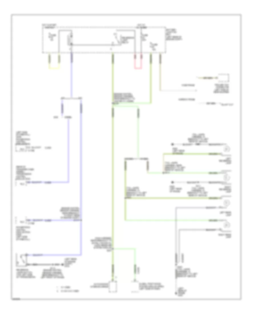
Cooling Fan Wiring Diagram for Ford F550 Super Duty 2010
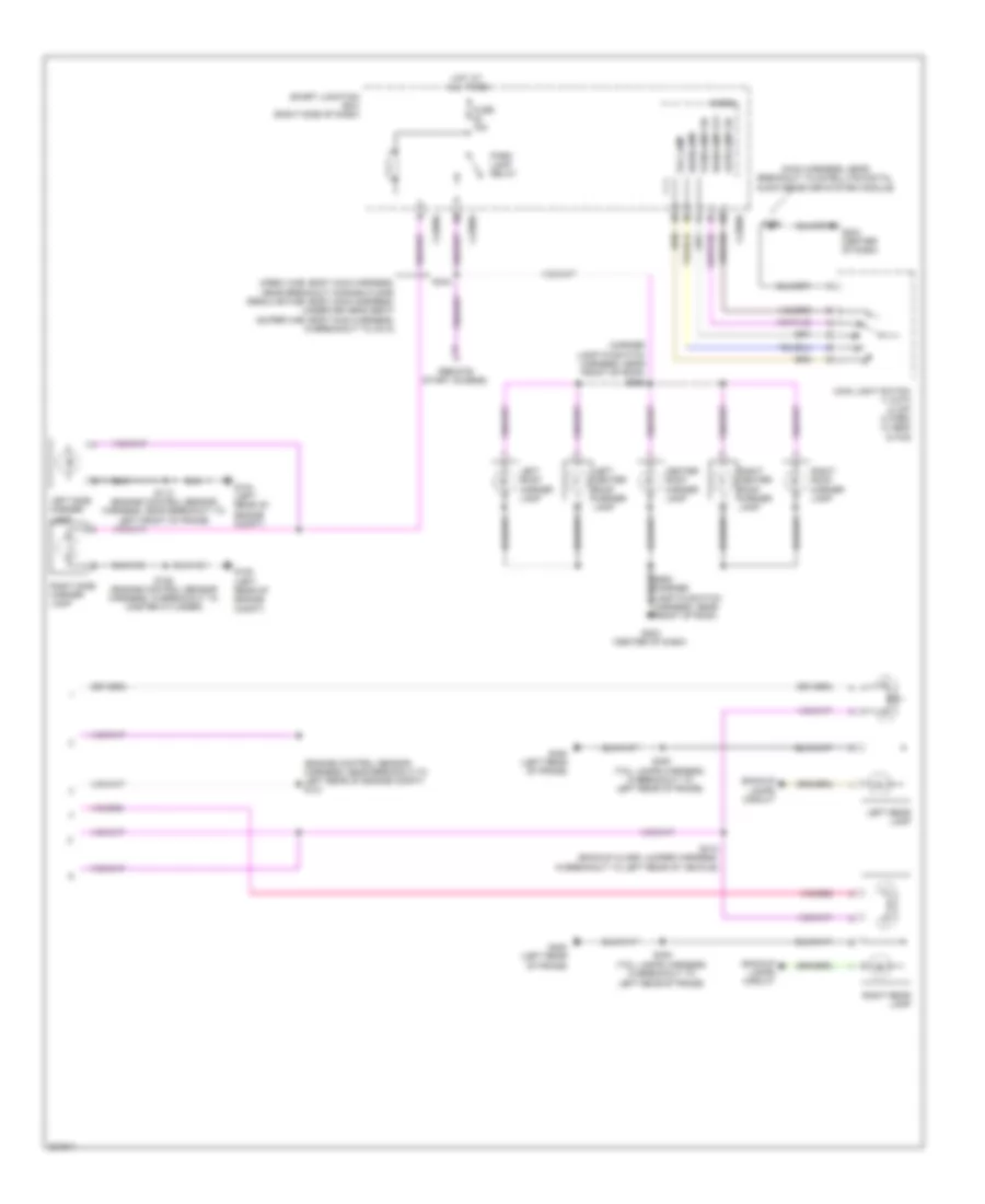
List of elements for Exterior Lamps Wiring Diagram (2 of 2) for Ford F550 Super Duty 2010:
41
(crew cab: body main harness, near breakout across floor) (regular cab: body main harness, under driver's seat) (super cab: body main harness, in breakout to c313)
(engine control sensor harness, in breakout to master cylinder)
(engine control sensor harness, near breakout to left front of frame)
(engine control sensor harness, near breakout to left rear of engine compt) s121
(main harness, near breakout to satellite digital audio receiver system module)
(marker lamp-to-switch harness, near front of roof) s906
(remote start access)
Autolamp on
Backup lamps circuit
C2280b
C2280d
C2280e
Center roof marker lamp
Fog lamp
Fuse 15a
G104 (left rear of engine compt)
G108 (left rear of engine compt)
G203 (center of dash)
G400 (left rear of frame)
Headlamp
Headlamp off
Hot at all times
Left center roof marker lamp
Left rear lamp
Left roof marker lamp
Left side marker lamp
Main light switch 1) auto 2) off 3) park 4) head 5) fog
Micro
Park lamp relay
Parklamp on
Right center roof marker lamp
Right rear lamp
Right roof marker lamp
Right side marker lamp
S113
S128
S286
S344
S400 (tail lamps harness, in breakout to left rear of frame)
S412 (backup alarm jumper harness, in breakout to left rear of vehicle)
Smart junction box (right side of dash)
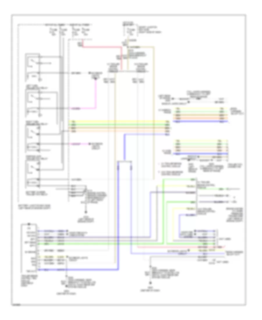
Trailer/Camper Adapter Wiring Diagram for Ford F550 Super Duty 2010
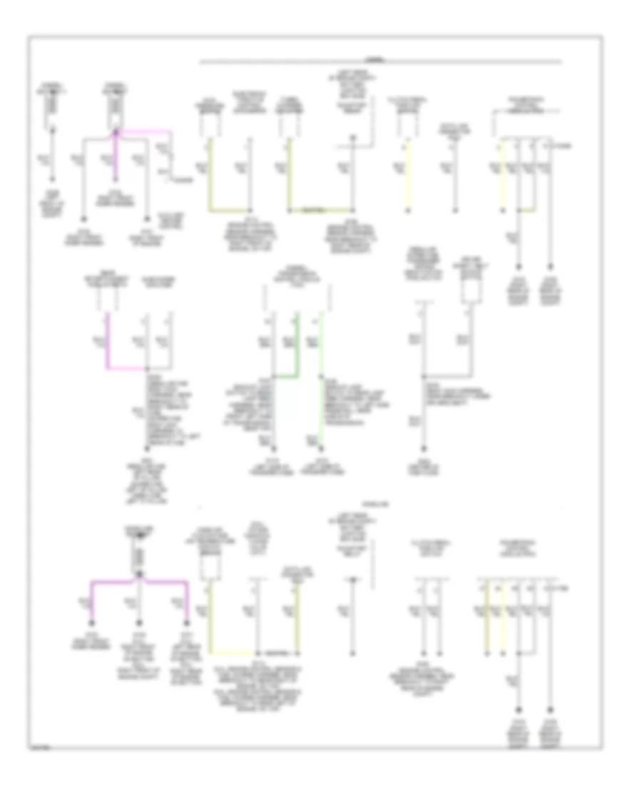
List of elements for Ground Distribution Wiring Diagram (1 of 5) for Ford F550 Super Duty 2010:
42
(6.8l) intake manifold tuning valve (imtv)
(diesel) battery
(diesel) battery ii
(diesel) transmission control module (tcm)
(gasoline) battery
(left rear of engine compt) battery junction box (bjb)
(regular/ super cab) passenger air bag deactivation (pad) switch
Auxiliary heater control
C1232b
C175b
C2463b
Clutch pedal position switch
Data link connector (dlc)
Diesel
Driver safety belt buckle switch
Dual pressure switch
Electronic throttle control (etc) motor
G100 (right front inner fender)
G101 (5.4l: left rear of engine, on bottom) (6.8l: right rear of engine, on bottom)
G101 (right front of engine)
G102 (5.4l: right front of engine, on bottom) (6.8l: right front of engine compt)
G102 (right front inner fender)
G103 (right rear of engine compt)
G106 (right rear of engine compt)
G107 (left side of transfer case)
G109 (left front of engine compt)
G116 (left side of transfer case)
G301 (regular cab: left rear "b" pillar) (super cab: left "b" pillar) (crew cab: left "c" pillar)
G303 (center of cab floor)
Gasoline
Mass air flow/intake air temperature (maf/iat) sensor
Powertrain control module (pcm)
Rear entertainment module (retm)
Run/start relay
S114 (5.4l: engine control sensor & fuel charge harness, near breakout to rear right of engine, on top) (6.8l: engine control sensor & fuel charge harness, near breakout to rear left of engine, on top)
S114 (engine control sensor harness, near breakout to right front of engine, on top)
S162 (engine control sensor harness, near breakout to right rear of engine compt)
S190 (backup lamp switch to rear lamp feed harness, near breakout to left side frame rail, near middle of transmission)
S191 (backup lamp switch to rear lamp feed harness, near breakout to front left side of transmission, near top)
S316 (body main harness, near breakout under driver's seat)
Subwoofer amplifier
Turbo charger actuator
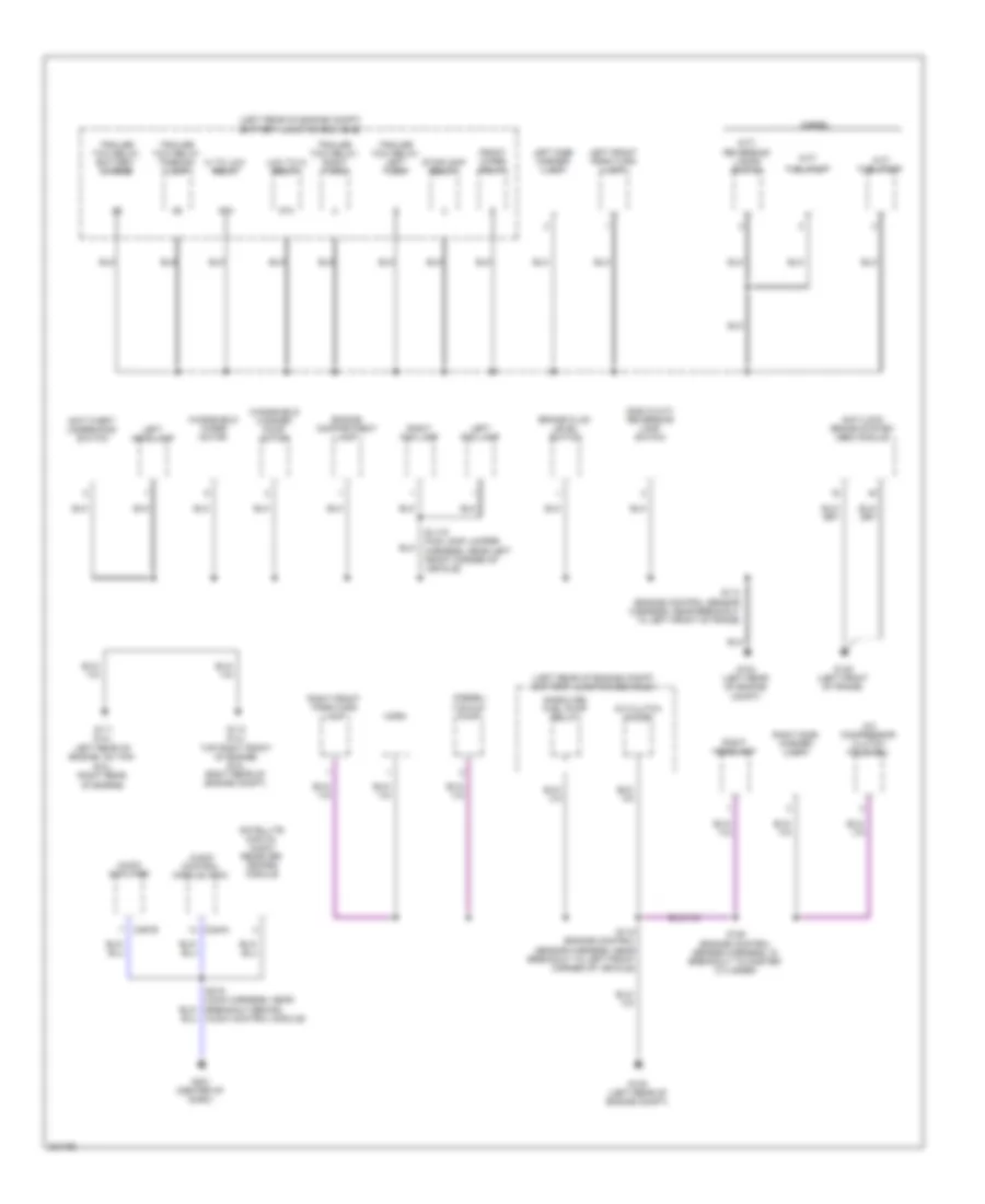
Ground Distribution Wiring Diagram (2 of 5) for Ford F550 Super Duty 2010
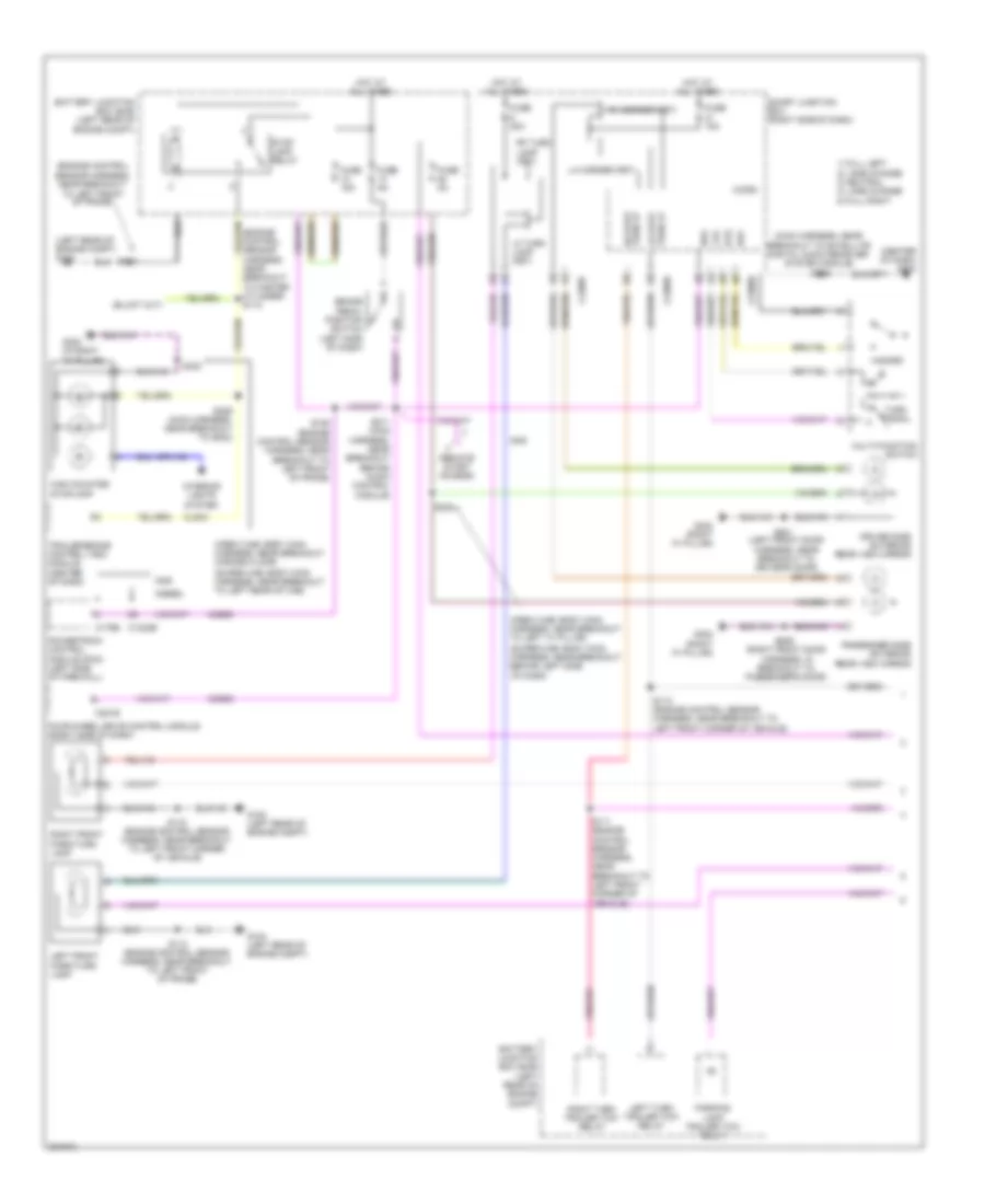
List of elements for Courtesy Lamps Wiring Diagram for Ford F550 Super Duty 2010:
80
(body main harness, near breakout to right "a" pillar) s307
(crew cab: body main harness,
(crew cab: body main harness, near breakout across floor) (super cab: body main harness, near breakout to left rear of cab)
(crew cab: body main harness, near breakout to left "a" pillar) (super cab: body main harness, near breakout behind left side of dash)
(crew cab: body main harness, near breakout under center console) (regular cab: body main harness, near breakout to center of cab floor, near rear of cab)
(interior lamp feed harness, near right "a" pillar)
(interior lamp feed harness, near right "a" pillar) s908
(interior lamp feed harness, near right "a" pillar) s909
(left front door harness, near
(left rear of
(main harness, near breakout behind audio control module) s214
(regular cab: body main harness, near
(regular cab: body main harness, near breakout to left "b" pillar) (super cab: body main harness, near breakout to right "a" pillar)
(regular cab: body main harness, near breakout to right rear of cab) (except regular cab: body main harness, near breakout to center console)
(right "a" pillar) g302
(right front door harness, in breakout to passenger's door)
(super cab: body main harness, near breakout under passenger's seat)
Ajar
Battery saver relay
Breakout to center of cab floor,
Breakout to driver's door)
C2280a
C2280b
C2280c
C2280d
C921b
Cln03
Cln09
Console)
Dim
Dim sw gnd
Dimmer sw
Dome
Dome lp
Driver side front door ajar switch (driver's door)
Driver side rear door ajar switch (left rear door)
Engine compartment lamp
Exterior lights system
Floor lamp (fet)
Front interior/map lamps assembly (w/ crew cab or w/o roof opening panel)
Fuse 10 15a
Fuse 25 10a
Fuse 9 15a
G104 (left rear of engine compt)
G302 (right "a" pillar)
G400
G400 (left rear of luggage compt)
Gd179
High mounted stoplamp
Hot at all times
Instrument panel dimmer switch
Interior lighting (fet)
Left front running board lamp
Left rear running board lamp
Left vanity mirror lamp
Luggage compt)
Micro
Near breakout under center
Near rear of cab)
Passenger side front door ajar switch (front passenger's door)
Passenger side rear door ajar switch (right rear door)
List of elements for Instrument Illumination Wiring Diagram for Ford F550 Super Duty 2010:
71
(base audio)
(center of dash)
(center of dash) g203
(main harness, near break- out to satellite digital audio
(main harness, near breakout behind audio control module) s214
(main harness, near breakout behind audio control module) s220
(main harness, near breakout to satellite digital audio receiver system module)
1) auto 2) off 3) park 4) head 5) fog
Adjustable pedal switch
Audio control module (acm)
Auto-dimming interior mirror
Autolamp on
Backlighting led (fet)
C218a
C218b
C2280b
C2280d
C240a
Clockspring (steering column assembly)
Dim
Dim sw gnd
Dimmer sw
Dome
Dome lp
Driver side door lock switch
Flash-to-pass
Fog lamp
Fog lamp ind
Four-wheel drive switch
Ftp
Fuse 10 15a
Fuse 41 15a
G202 (center of dash)
G203
G203 (center of dash)
G203 (center of dash)
G204
G302 (in right "a" pillar)
G302 (right "a" pillar)
Gd115
Headlamp off
Headlamp on
Headlights system
Hi beam
Hot at all times
Hot w/ accessory delay relay energized
Instrument panel dimmer switch
Main light switch
Message center module switch
Micro
Multifunction switch
Parklamp on
Passenger side door lock switch
Power sliding rear window switch
Receiver system module)
Roof panel opening switch
S235 (main harness, near break- out to satellite digital audio receiver system module)
S235 (main harness, near breakout to satellite digital audio receiver system module)
S239
S249 (relay feed harness, behind glove box)
S286
S286 (main harness, near breakout to satellite digital audio receiver system module)
S301 (crew cab: body main harness, near breakout across floor) (regular cab: body main harness, near breakout to passenger safety belt retractor pretensioner) (super cab: body main harness, near breakout under passenger's seat)
S501 (left front door harness, near right "a" pillar)
S639 (interior lamp feed harness, near right "a" pillar)
S907 (interior lamp feed harness, near right "a" pillar)
Smart junction box (sjb) (right side of dash)
Steering wheel/ speed control switch
Traction control switch
Upfitter switch
Vln04
MEMORY SYSTEMS
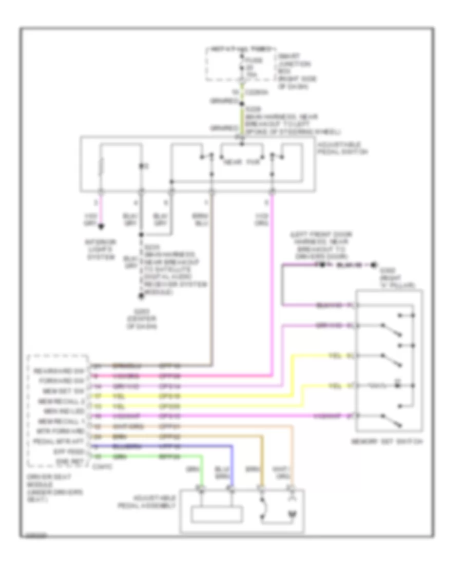
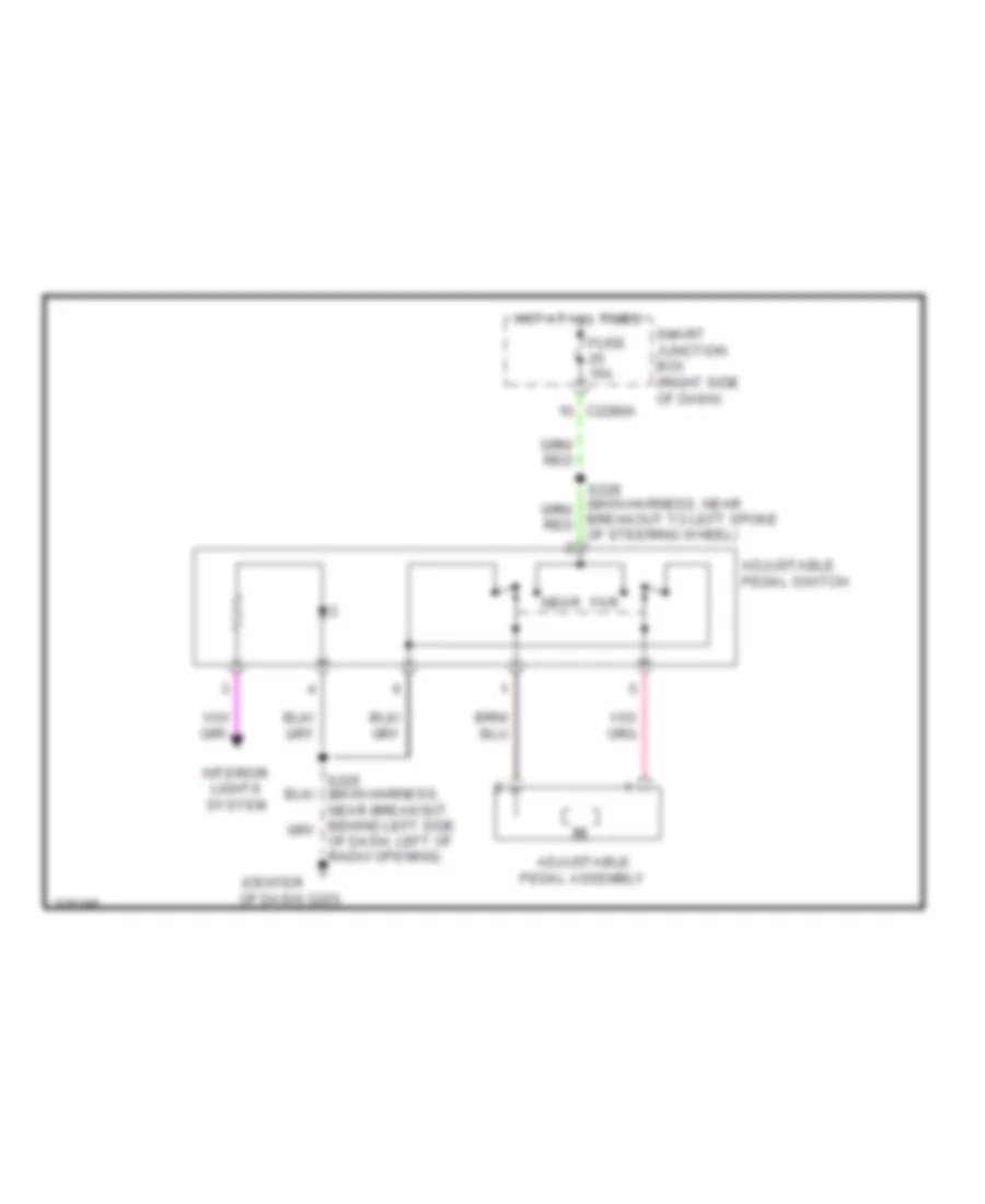
Adjustable Pedal Wiring Diagram for Ford F550 Super Duty 2010
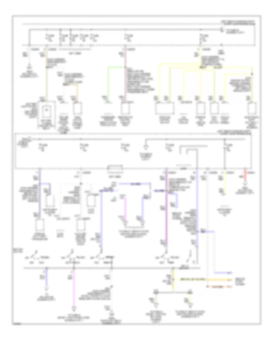
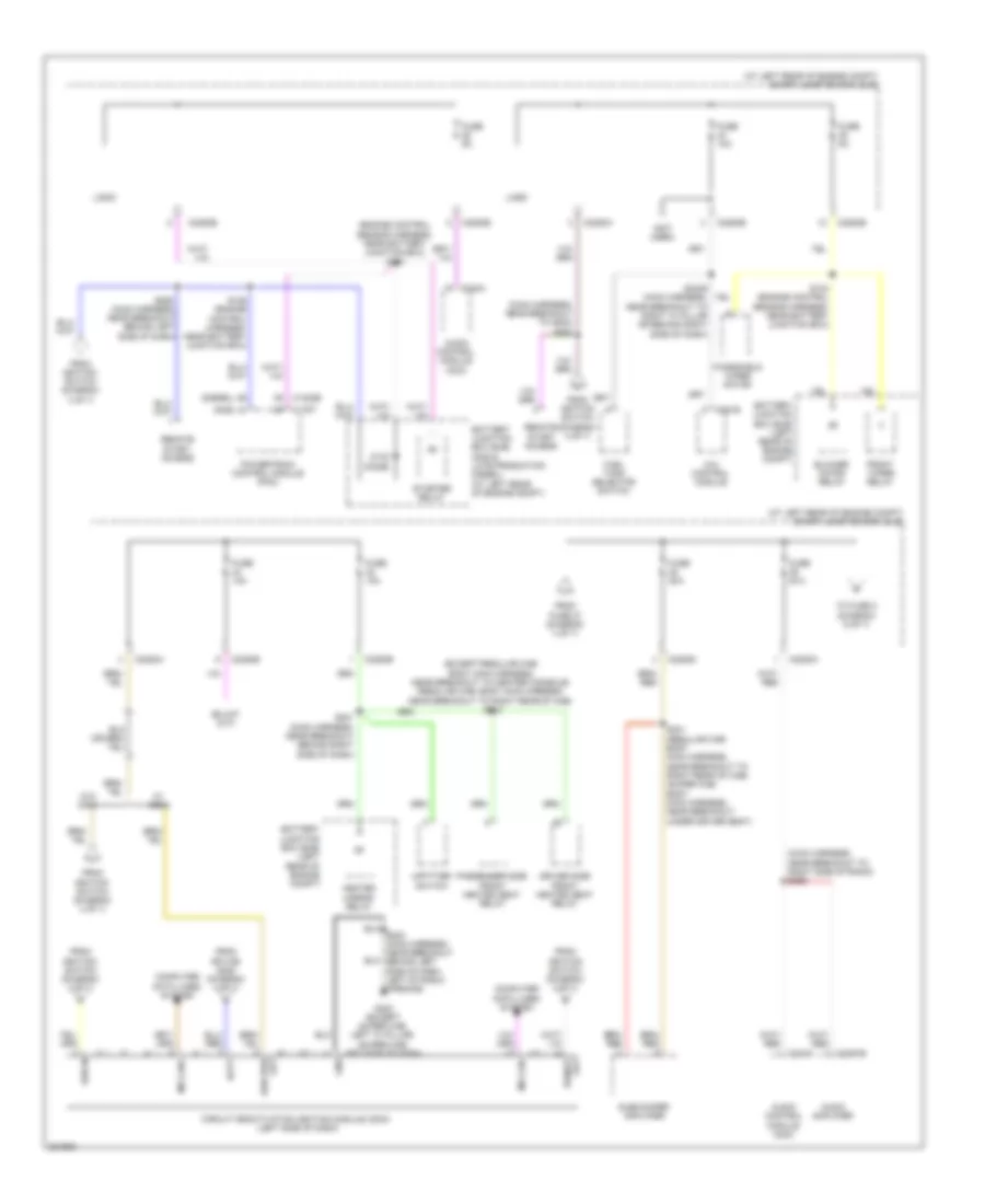
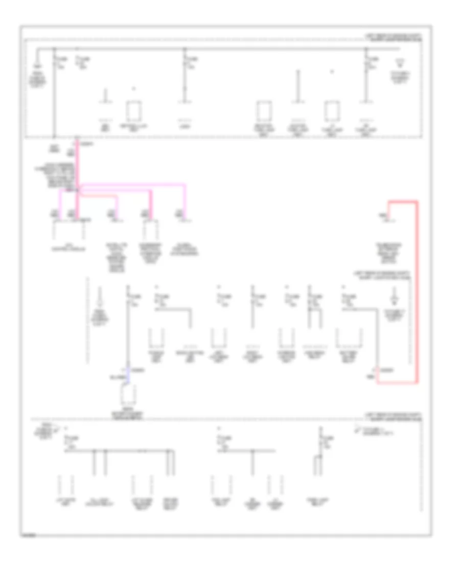
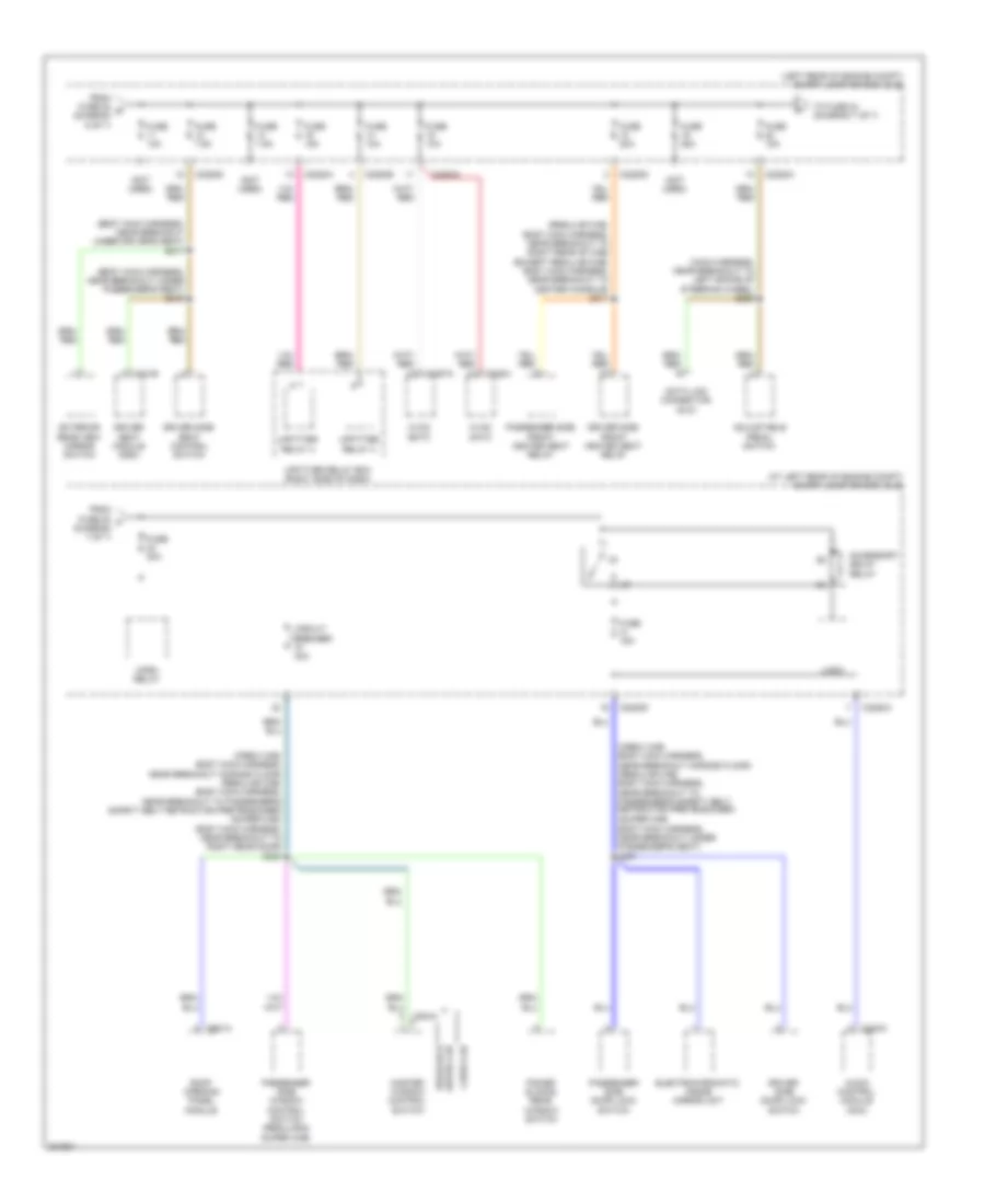
List of elements for Power Distribution Wiring Diagram (1 of 7) for Ford F550 Super Duty 2010:
47
(alternator rectifier system harness, in breakout to left front of engine compt) red
(alternator rectifier system harness, in breakout to right front of engine compt) (gas) s137
(diesel)
(diesel: engine control sensor harness, near right front side of engine) (gas: engine control sensor harness, near breakout to right front of engine compt) s153
(engine control sensor harness, near breakout to right front of engine compt) (diesel) s1014
(engine control sensor harness, near breakout to right front of engine compt) s160
(gas)
150a
Auxiliary heater control module
Battery
Battery ii (diesel)
C102a
C102c
C1104a
C1104c
C1251a
C1251c
C197a
C2463a
Cable pro
Diesel
Diesel w/ dual generators
G100 (right front inner fender)
G101 (diesel: right front of engine 5.4l: left rear of engine, on bottom 6.8l: right rear of engine, on bottom)
G102 (diesel: right front inner fender 5.4l: right front of engine, on bottom 6.8l: right front of engine compt)
G109 (left front of engine compt)
Gas
Generator
Nca
Red
S1015 (diesel) (engine control sensor harness, near breakout to right front of engine compt)
S1016 (diesel) (engine control sensor harness, near breakout to right front of engine compt)
S1017 (diesel) (engine control sensor harness, near breakout to right front of engine compt)
S138 (gas) (alternator rectifier system harness, in breakout to right front of engine compt)
S139
S139 (gas) (alternator rectifier system harness, in breakout to right front of engine compt)
S140 (alternator rectifier system harness, in breakout to left front of engine compt)
S141 (alternator rectifier system harness, in breakout to left front of engine compt)
S143 (alternator rectifier system harness, in breakout to right front of engine compt)
S144 (alternator rectifier system harness, in breakout to right front of engine compt)
S145 (alternator rectifier system harness, in breakout to right front of engine compt)
S152 (diesel: engine control sensor harness, near right front of engine) (gas: engine control sensor harness, near breakout to right front of engine compt)
S161 (engine control sensor harness, near breakout to right front of engine compt)
Secondary generator
Starter motor
To fuse 26 (smart junction box (sjb)) (diagram 4 of 7)
To fuse 40 (battery junction box (bjb)) (diagram 2 of 7)
Power Distribution Wiring Diagram (2 of 7) for Ford F550 Super Duty 2010
List of elements for Power Distribution Wiring Diagram (4 of 7) for Ford F550 Super Duty 2010:
61
(left rear of engine compt) smart junction box (sjb)
(main harness, near breakout on front of steering column, near bottom) s240
(main harness, near breakout to c215) s216
(main harness, near breakout to satellite digital audio receiver system module)
(not used)
4x4 control module
Acc
Auxiliary heater control module (ahcm)
Battery charge trailer tow relay
Battery junction box (bjb) (left rear of engine compt)
C2280a
C2280b
C2280d
C2280e
C2280h
C2357a
C2463c
C281b
Electronic shift on the fly (esof) solenoid
From h fuse 35 (diagram 4 of 7)
From run/start relay (diagram 3 of 7)
From splice s119 (diagram 3 of 7)
From splice s152 (diagram 1 of 7)
Fuse 10a
Fuse 20a
Fuse 5a
Fuse 7.5a
Hvac datc
Hvac emtc
Ignition switch
Instrument cluster (ic)
Key in switch
Logic
Off
Parking aid module (pam)
Passenger air bag deactivation (pad) switch
Passive anti-theft transceiver
Red
Remote start access
Restraints control module (rcm)
Run
S105 (engine control sensor harness, in breakout to left rear of engine compt)
S206 (main harness, near breakout to right side of hvac housing)
S223 (main harness, near breakout behind left side of dash, left of radio opening)
S233 (main harness, near breakout to satellite digital audio receiver system module)
S283
S314 (regular cab: body main harness, near breakout to center of cab floor, near rear of cab super cab: body main harness, near breakout under passenger seat)
Start
Tele- matics module (w/crew chief)
To circuit deactivation ignition module (cdim) (diagram 5 of 7)
To fuse 36 (diagram 4 of 7)
To fuse 38 (diagram 5 of 7)
To fuse 43 (smart junction box (sjb)) (diagram 5 of 7)
To fuse 44 (smart junction box (sjb)) (diagram 5 of 7)
To splice s126 (diagram 5 of 7)
Towl haul switch
Traction control switch
Trailer brake control (tbc) module (w/o crew chief)
Vacuum pump (diesel)
W/ cdim
W/o cdim
Power Distribution Wiring Diagram (5 of 7) for Ford F550 Super Duty 2010
List of elements for Power Distribution Wiring Diagram (7 of 7) for Ford F550 Super Duty 2010:
53
(at left rear of engine compt) smart junction box (sjb)
(body main harness, near breakout under driver's seat)
(body main harness, near breakout under passenger's seat) s315
(crew cab: body main harness, near breakout across floor) (regular cab: body main harness, near breakout to passenger's safety belt retractor pretensioner)
(crew cab: body main harness, near breakout across floor) (regular cab: body main harness, near breakout to passenger's safety belt retractor pretensioner) (super cab: body main harness, near breakout to right rear door) s303
(left rear of engine compt) smart junction box (sjb)
(main harness, near breakout to left spoke of steering wheel) s228
(not used)
(regular cab: body main harness, near breakout to right rear of cab) (except regular cab: body main harness, near breakout to center console) s311
(super cab: body main harness, near breakout under passenger's seat) s301
Accessory delay relay
Adjustable pedal switch
Audio control module (acm)
C2280a
C2280b
C2280d
C228a
C2357a
C240a
C341b
C921a
Circuit breaker 30a
Crew cab
Data link connector (dlc)
Driver seat module (dsm)
Driver side door lock switch
Driver side front heated seat relay
Driver side seat control switch
Electrochromatic inside mirror unit
Exterior rear view mirror switch
From fuse 20 t (diagram 7 of 7)
From fuse 22 s (diagram 6 of 7)
Fuse 10a
Fuse 15a
Fuse 20a
Fuse 25a
Fuse 7.5a
Horn relay
Hvac datc
Hvac emtc
Logic
Master window control switch
Passenger side door lock switch
Passenger side front heated seat relay
Passenger side window control switch (regular & super cab)
Power sliding rear window switch
Regular & super cab
Roof opening panel module
S317
To fuse 24 (diagram 7 of 7)
Upfitter relay 3
Upfitter relay 4
Upfitter relay box (right side of dash)
POWER DOOR LOCKS
Power Door Locks Wiring Diagram (1 of 2) for Ford F550 Super Duty 2010
List of elements for Power Door Locks Wiring Diagram (1 of 2) for Ford F550 Super Duty 2010:
30
(crew cab: body main harness, near breakout to right "a" pillar) (regular cab: body main harness, near breakout to passenger safety belt retractor pretensioner) (super cab: body main harness, near breakout under passenger's seat)
(regular cab: body main harness, near breakout across floor) (super cab: body main harness, near breakout to passenger safety belt retractor pretensioner) (crew cab: body main harness, near breakout under passenger's seat)
(super cab: body main harness, near breakout under passenger's seat) (crew cab: body main harness, near breakout to right "b" pillar) (regular cab: body main harness, near breakout to passenger safety belt retractor pretensioner)
All lock/ unlock relay
Antenna
Breakout to left "b" pillar) (super cab: body main harness, near breakout to right "a" pillar)
Breakout to right
C2280c
C2280d
Control
Driver side door lock switch
Driver unlock relay
Fuse 15a
Fuse 20a
G302 (right "a" pillar)
Hot at all times
Hot w/ accessory delay relay energized
Hsd
Lock
Logic
Passenger side door lock switch
Remote start access
Rke receiver internal antenna
S301
S305
S306
S308
Sense
Smart junction box (sjb) (left rear of engine compt)
Un lock
Power Door Locks Wiring Diagram (2 of 2) for Ford F550 Super Duty 2010
List of elements for Power Door Locks Wiring Diagram (2 of 2) for Ford F550 Super Duty 2010:
26
(crew cab only)
(driver's door) driver side front door ajar switch
(front passenger's door) passenger side front door ajar switch
(left front door) left front door lock actuator
(left rear door harness, in breakout to left "b" pillar) s800
(left rear door)
(left rear door) driver side rear door ajar switch
(right rear door harness, in breakout to left "b" pillar) s700
(right rear door)
(right rear door) passenger side rear door ajar switch
1/2
3/4
5/6
7/8
9/0
Ajar
G300 (super cab: behind left side of dash) (except super cab: left "a" pillar)
G302 (right "a" pillar)
Keypad switch assembly
Left rear door lock actuator
Passenger side door lock actuator (passenger's door)
Right rear door lock actuator
S302 (crew cab: body main harness, near breakout across floor) (regular cab: body main harness, near breakout to passenger safety belt retractor pretensioner) (super cab: body main harness, near breakout under passenger's seat)
S308 (regular cab: body main harness, near breakout to left "b" pillar) (super cab: body main harness, near breakout to right
S326 (crew cab: body main harness, near breakout to left "a" pillar) (super cab: body main harness, near breakout behind left side of dash)
S333 (body main harness, near breakout under passenger's seat)
POWER MIRRORS
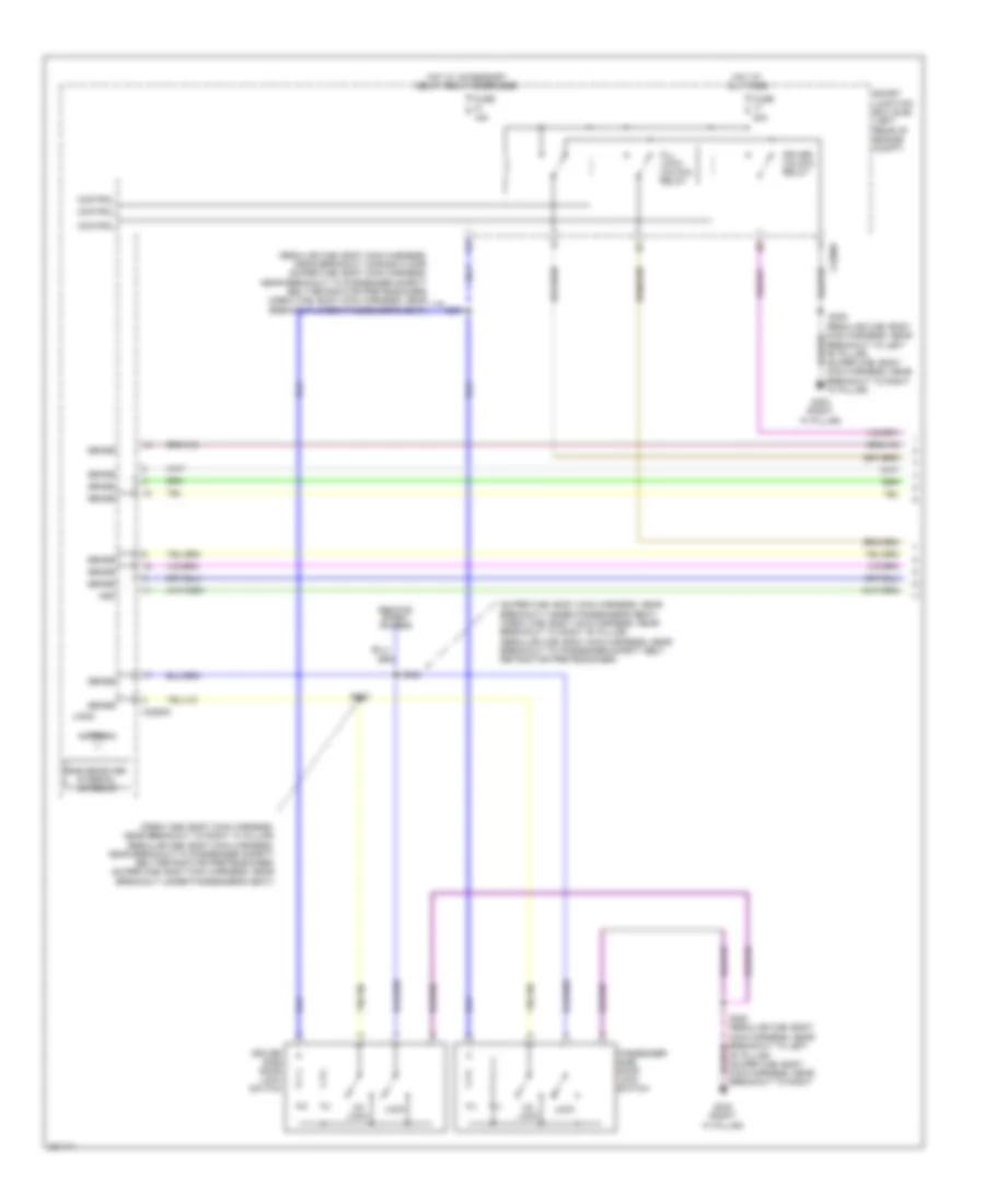
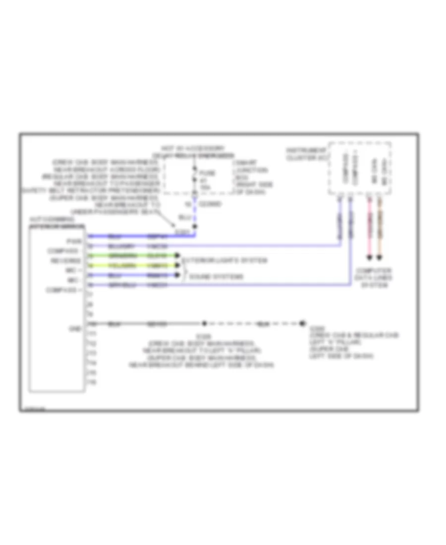
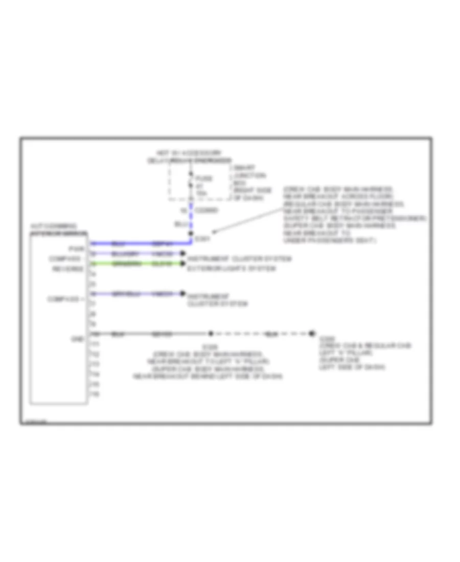
Electrochromic Mirror Wiring Diagram, with Microphone without Video for Ford F550 Super Duty 2010
List of elements for Electrochromic Mirror Wiring Diagram, with Microphone without Video for Ford F550 Super Duty 2010:
29
(crew cab: body main harness, near breakout across floor) (regular cab: body main harness, near breakout to passenger safety belt retractor pretensioner) (super cab: body main harness, near breakout to under passenger's seat)
Auto-dimming interior mirror
C2280d
Cbp41
Cls10
Compass +
Compass -
Computer data lines system
Exterior lights system
Fuse 15a
G300 (crew cab & regular cab: left "a" pillar) (super cab: left side of dash)
Gd133
Gnd
Hot w/ accessory delay relay energized
Instrument cluster (ic)
Mic +
Mic -
Ms can+
Ms can-
Pwr
Reverse
Rmm13
S301
S326 (crew cab: body main harness, near breakout to left "a" pillar) (super cab: body main harness, near breakout behind left side of dash)
Smart junction box (right side of dash)
Sound systems
Vmc30
Vmc31
Vmm13
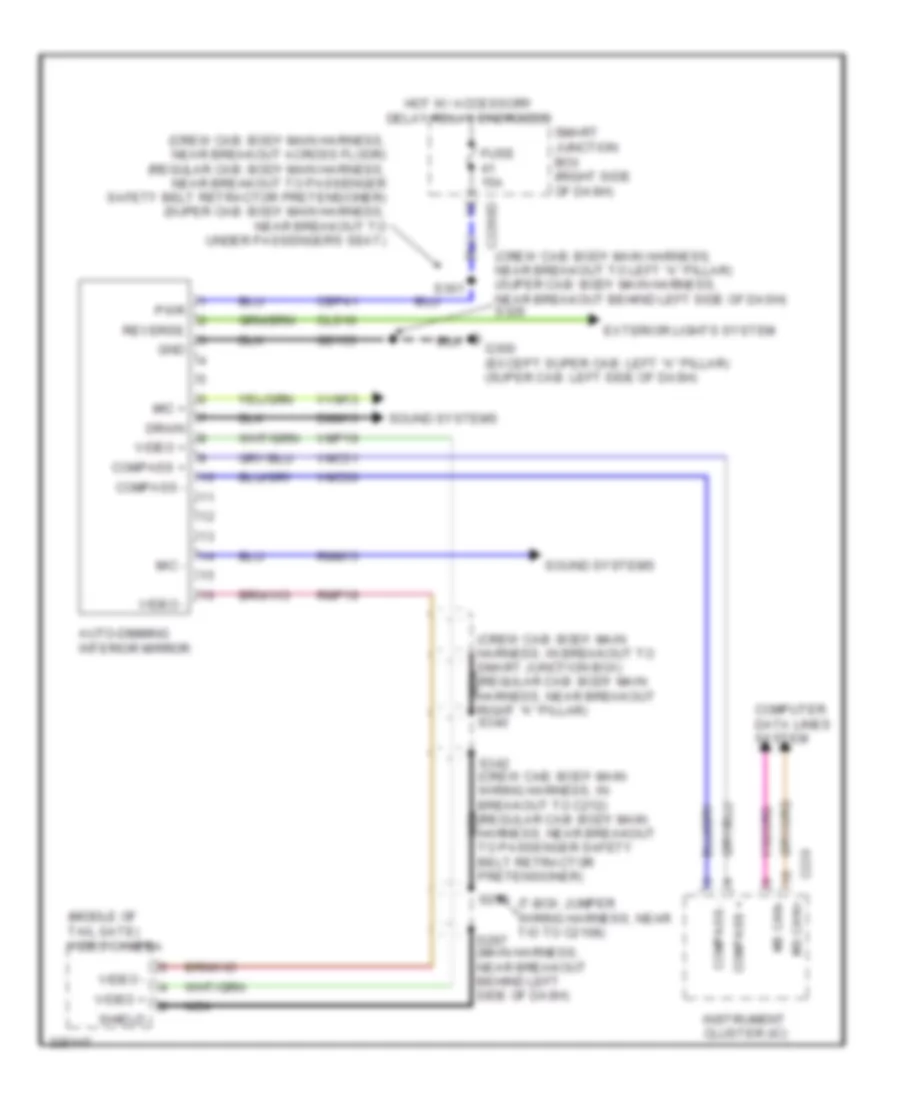
Electrochromic Mirror Wiring Diagram, with Video for Ford F550 Super Duty 2010
List of elements for Electrochromic Mirror Wiring Diagram, with Video for Ford F550 Super Duty 2010:
44
(crew cab: body main harness, in breakout to smart junction box) (regular cab: body main harness, near breakout nca right "a" pillar) s340
(crew cab: body main harness, near breakout across floor) (regular cab: body main harness, near breakout to passenger safety belt retractor pretensioner) (super cab: body main harness, near breakout to under passenger's seat)
(crew cab: body main harness, near breakout to left "a" pillar) (super cab: body main harness, near breakout behind left side of dash) s326
(middle of tail gate) video camera
(t-box jumper wiring harness, near t/o to c2108)
Auto-dimming interior mirror
C220
C2280d
Cbp41
Cls10
Compass +
Compass -
Computer data lines system
Dmm13
Drain
Exterior lights system
Fuse 15a
G300 (except super cab: left "a" pillar) (super cab: left side of dash)
Gd133
Gnd
Hot w/ accessory delay relay energized
Instrument cluster (ic)
Mic +
Mic -
Ms can+
Ms can-
Nca
Pwr
Reverse
Rmm13
Rmp19
S297 (main harness, near breakout behind left side of dash)
S298
S301
S342 (crew cab: body main wiring harness, in breakout to c212) (regular cab: body main harness, near breakout nca to passenger safety belt retractor pretensioner)
Shield
Smart junction box (right side of dash)
Sound systems
Video +
Video -
Vmc30
Vmc31
Vmp19
Vvm13
Electrochromic Mirror Wiring Diagram, without Microphone without Video for Ford F550 Super Duty 2010
List of elements for Electrochromic Mirror Wiring Diagram, without Microphone without Video for Ford F550 Super Duty 2010:
21
(crew cab: body main harness, near breakout across floor) (regular cab: body main harness, near breakout to passenger safety belt retractor pretensioner) (super cab: body main harness, near breakout to under passenger's seat)
Auto-dimming interior mirror
C2280d
Cbp41
Cls10
Compass +
Compass -
Exterior lights system
Fuse 15a
G300 (crew cab & regular cab: left "a" pillar) (super cab: left side of dash)
Gd133
Gnd
Hot w/ accessory delay relay energized
Instrument cluster system
Pwr
Reverse
S301
S326 (crew cab: body main harness, near breakout to left "a" pillar) (super cab: body main harness, near breakout behind left side of dash)
Smart junction box (right side of dash)
Vmc30
Vmc31
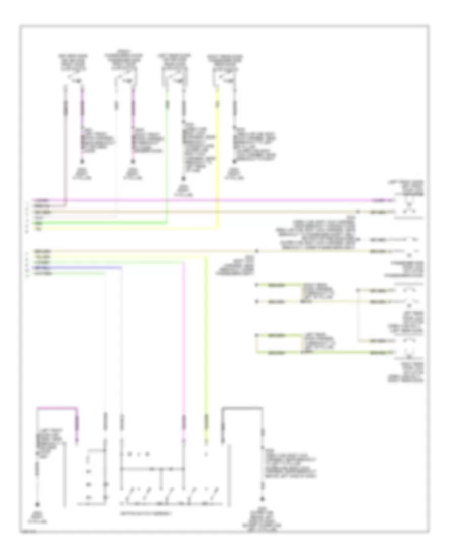
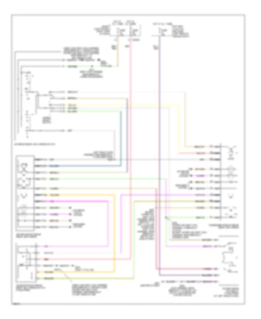
Power Mirrors Wiring Diagram for Ford F550 Super Duty 2010
List of elements for Power Windows Wiring Diagram, Except Crew Cab for Ford F550 Super Duty 2010:
33
(regular cab: body main harness, near breakout to passenger safety belt retractor pretensioner) (super cab: body main harness, near breakout to right rear door)
Accessory delay relay
Ain
Amp
Auto down sw
C2280d
Circuit breaker 30a
Control
Down
Driver side front power window motor (driver's door)
Drv sw
G203 (center of dash)
G302 (right "a" pillar)
Gnd
Hot at all times
Interior lights system
Master window control switch
Micro
Out
Pass sw
Passenger side front power window motor (passenger's door)
Passenger side window control switch
Power sliding rear window motor (center rear of cab)
Power sliding rear window switch
Relay contact
Rly coil
S286 (main harness, near breakout to satellite digital audio receiver system module)
S303
S501 (left front door harness, near breakout to driver's door)
Smart junction box (sjb) (left rear of engine compt)
Vdd
Xin
Xout
RADIO
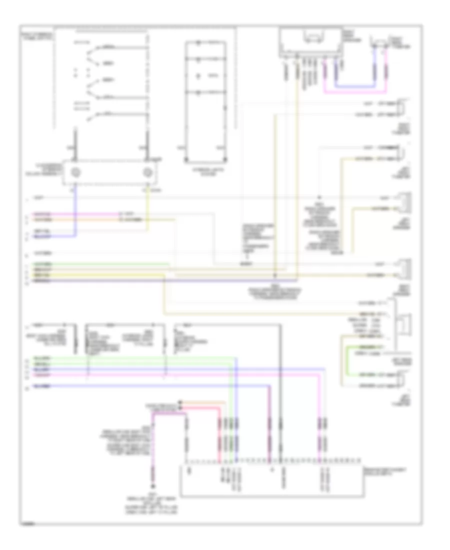
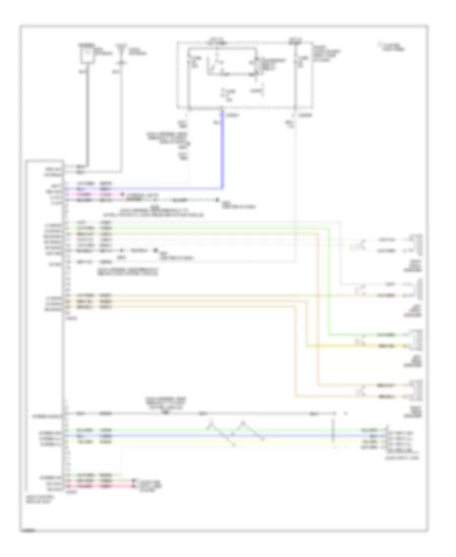
Audiophile Sound Radio Wiring Diagram (1 of 2) for Ford F550 Super Duty 2010
List of elements for 6.4L Diesel, A/T Wiring Diagram for Ford F550 Super Duty 2010:
97
(backup lamp switch to rear lamp feed harness, near breakout to top of transmission, near left of transmission) s196
(backup lamp switch to rear lamp feed harness, near breakout to top of transmission, near tail shaft housing)
(diesel-auto: backup lamp switch to rear lamp feed harness, near breakout to front left of transmission, near top) (diesel-manual: backup lamp switch to rear lamp feed harness, near breakout to right of transmission, near bottom)
(left side of firewall) powertrain control module (pcm)
(left side of transfer case)
(sspc-a) control a pressure solenoid shift
(sspc-b) control b pressure solenoid shift
(sspc-c) control c pressure solenoid shift
(sspc-d) control d pressure solenoid shift
(sspc-e) control e pressure solenoid shift
(tr-p) assembly sensor range transmission
Battery
Battery junction box (bjb) (left rear of engine compt)
C1232b
C2280b
C281a
Cat15
Cbb72
Cet05
Cet06
Cet07
Cet09
Cet21
Cet22
Cet25
Cet49
Cet50
Cls05
Cls28
Computer data lines system
Exterior lights system
Four-wheel drive control module (right side of dash)
Fuse 10a
Fuse 15a
Fuse 50a
G107 (left side of transfer case)
G116
Gd120
Gnd
Hot at all times
Hot in run or start
Hs can (+)
Hs can (-)
Hs can +
Hs can -
Instrument cluster (ic)
Iss
Le111
Nca
Oss
Output shaft speed (oss) sensor (top of transmission extension housing)
Pc-a
Pcm power relay
Re406
Ret04
Ret24
Rlc
S117
S190
S191
S192
S194
S198
S208 (main harness, near breakout to right side of hvac housing)
S227
Sbb37
Sensor temperature fluid transmission
Sig rtn
Smart junction box (cjb) (right side of dash)
Solenoid (pc-a) control pressure
Solenoid clutch converter torque
Speed sensor assembly (top left of transmission)
Sspc a
Sspc b
Sspc c
Sspc d
Sspc e
Tcc
Tcs
Tft
Tow haul switch (top of steering column)
Tow/haul indicator
Transmission control module (rear of transfer case)
Transmission torqshift
Trgnd
Tro n
Tro p
Trp
Tss
Vbpwr
Vdb04
Vdb05
Vdb06
Ve744
Vet27
Vet33
Vpwr
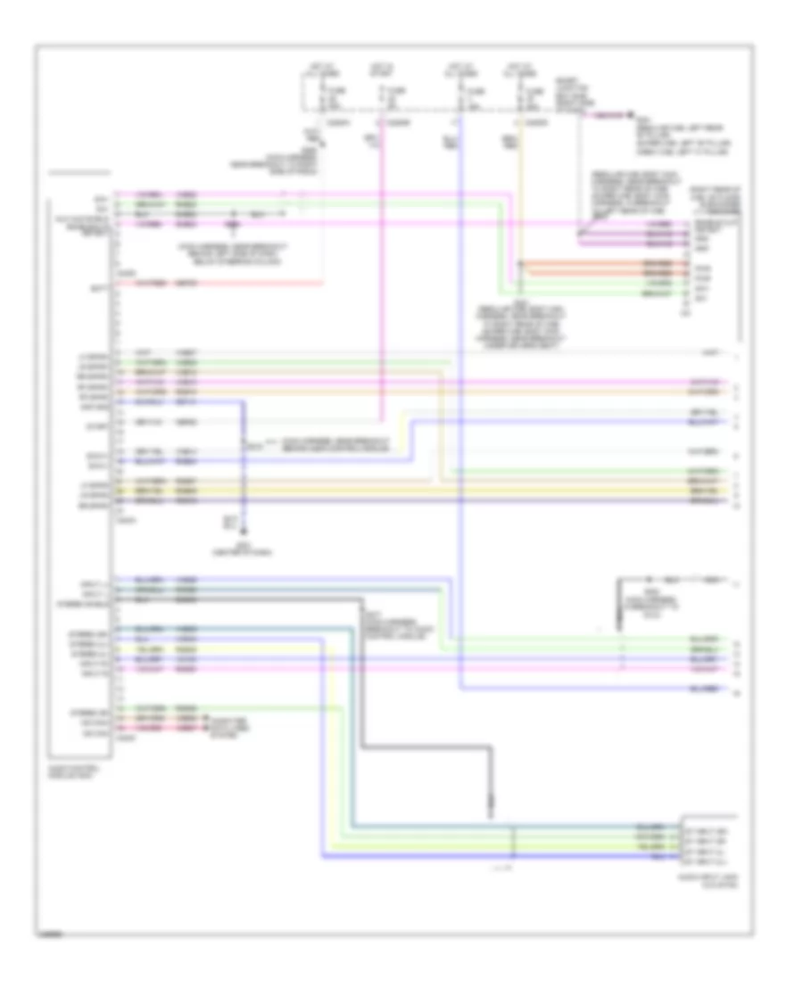
6.8L
6.8L, 4WD Wiring Diagram for Ford F550 Super Duty 2010
We use cookies to enhance your browsing experience, serve
personalized ads or content, and analyze our traffic. By clicking "Accept All",
you consent to our use of cookies. Privacy Policy