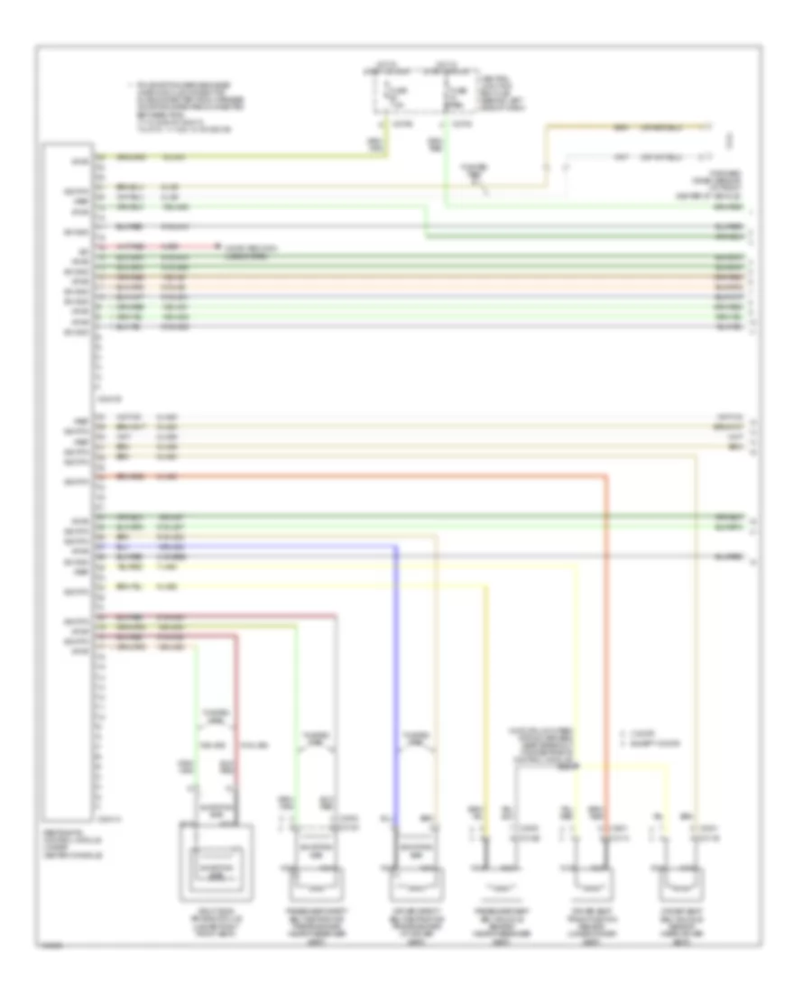
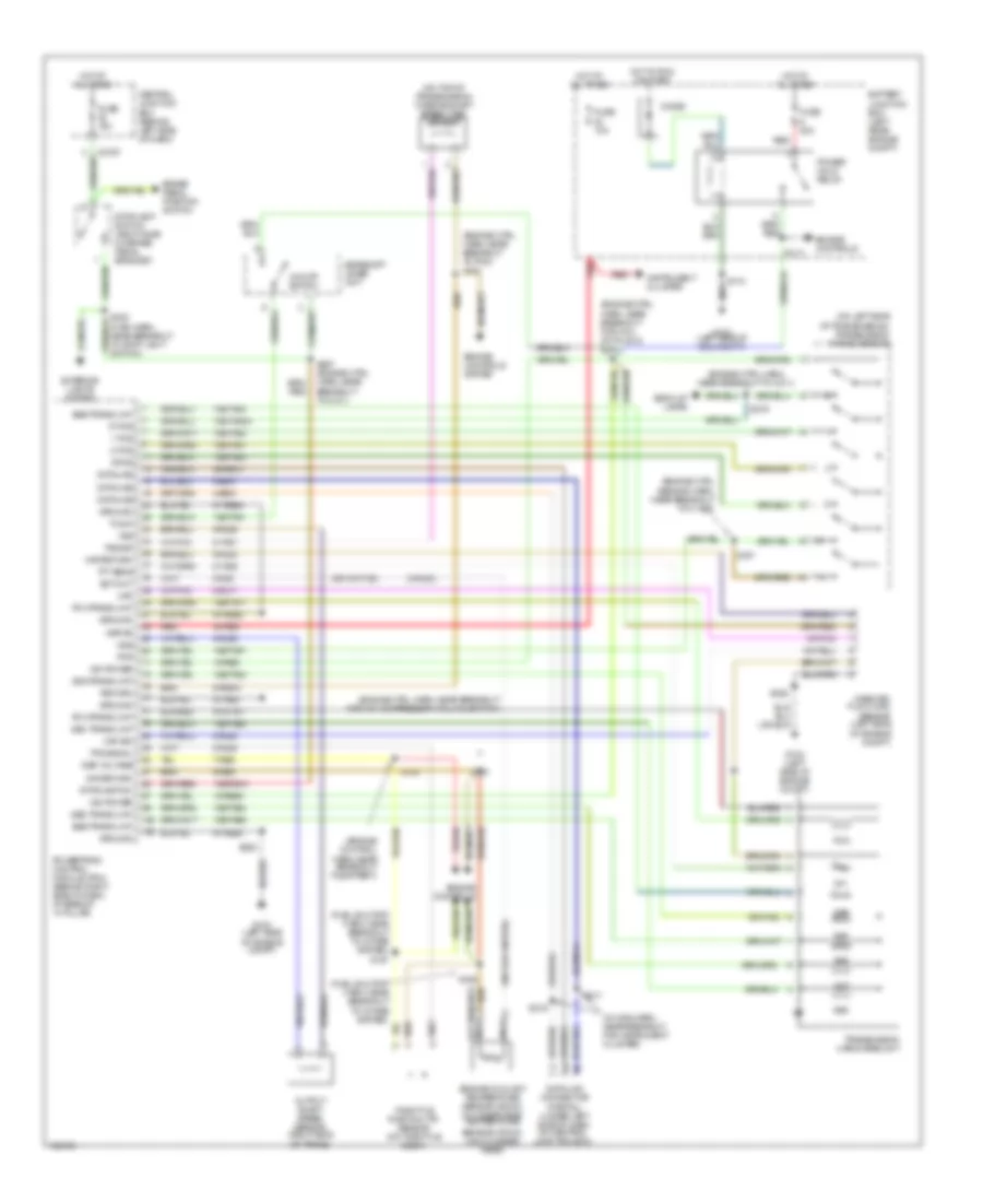
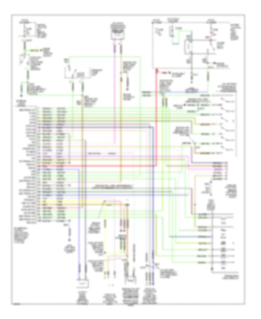
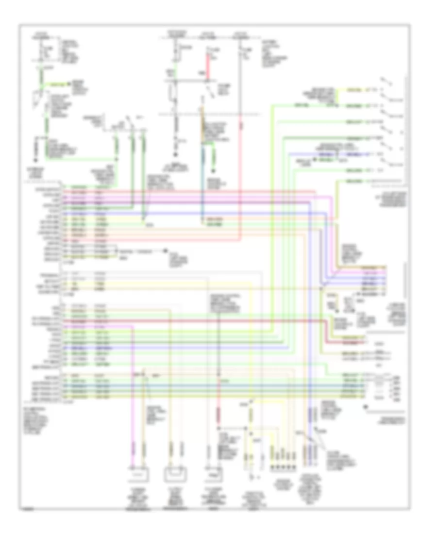
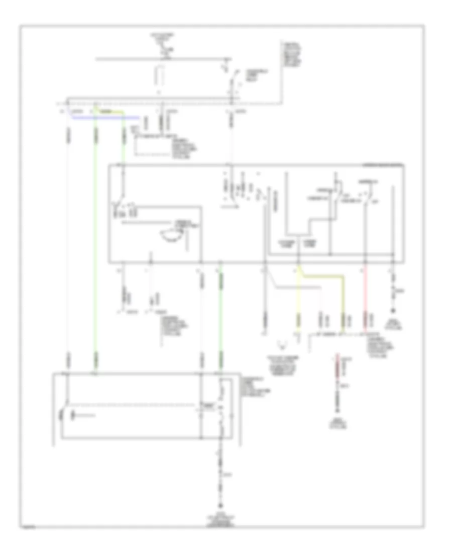
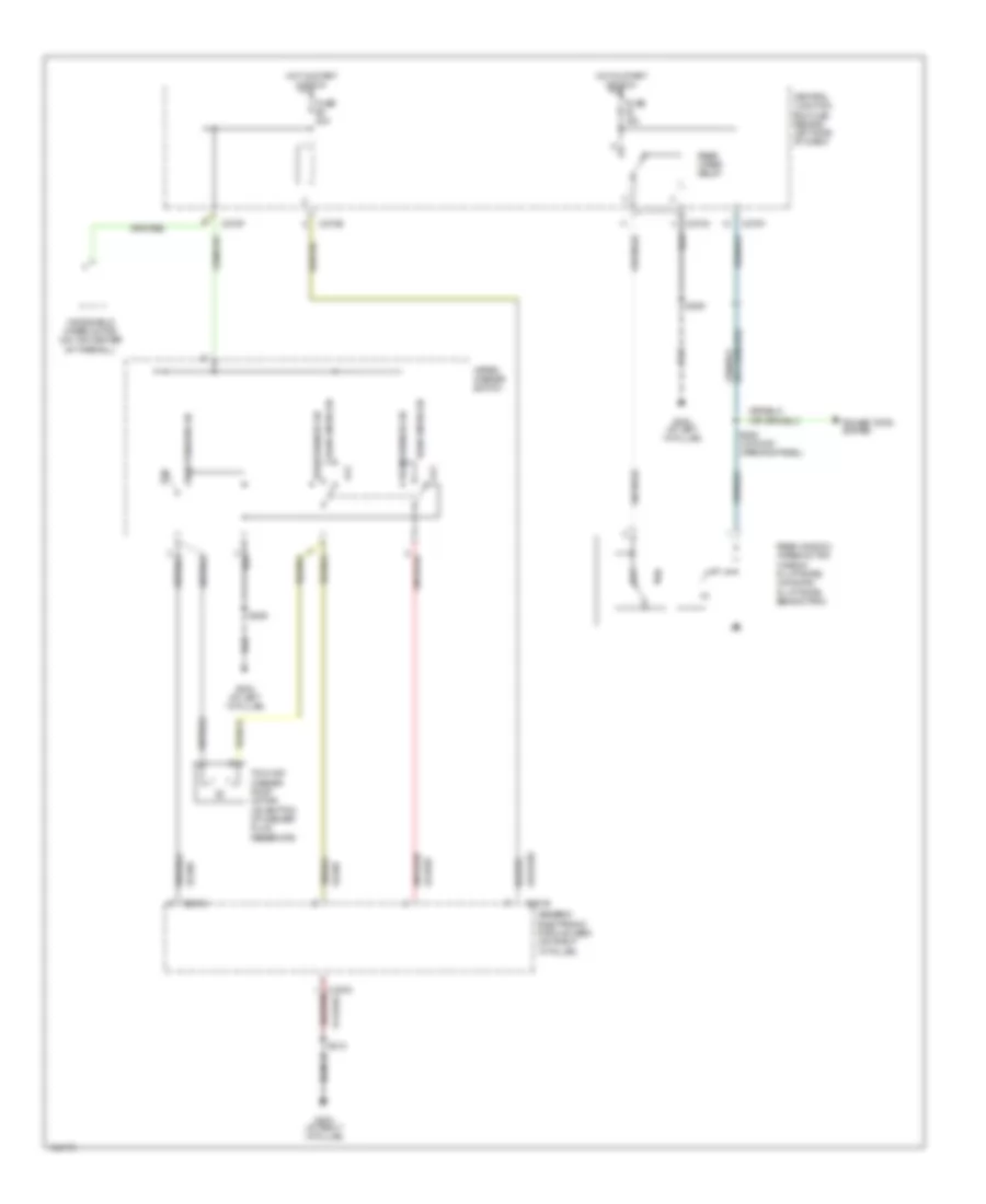
Diagram sections — 29 (82 total)
AIR CONDITIONING ANTI-LOCK BRAKES ANTI-THEFT BODY CONTROL MODULES COMPUTER DATA LINES COOLING FAN CRUISE CONTROL DEFOGGERS ENGINE PERFORMANCE EXTERIOR LIGHTS GROUND DISTRIBUTION HEADLIGHTS HORN INSTRUMENT CLUSTER INTERIOR LIGHTS POWER DISTRIBUTION POWER DOOR LOCKS POWER MIRRORS POWER SEATS POWER TOP/SUNROOF POWER WINDOWS RADIO SHIFT INTERLOCK STARTING/CHARGING SUPPLEMENTAL RESTRAINTS TRANSMISSION TRUNK, TAILGATE, FUEL DOOR WARNING SYSTEMS WIPER/WASHER
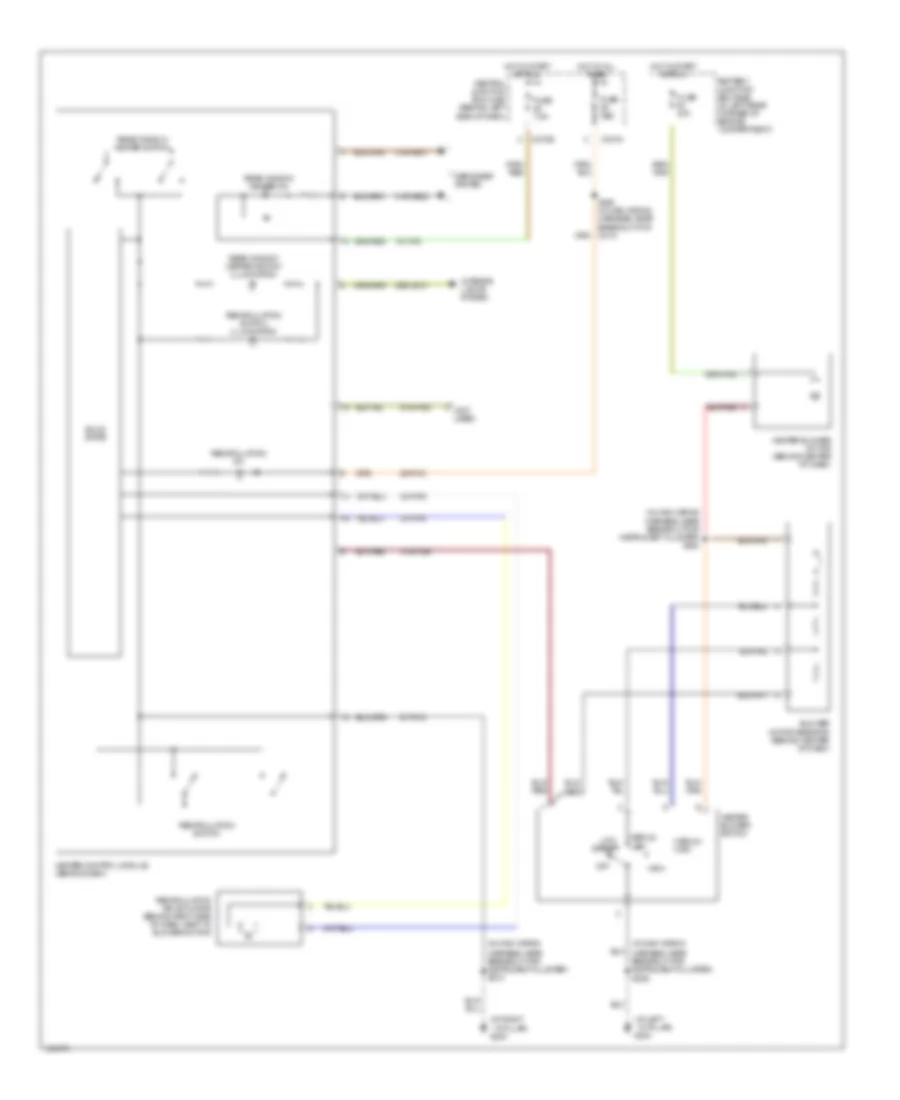
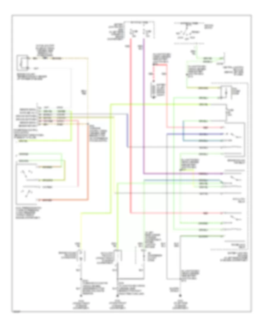
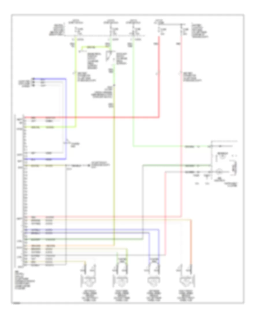
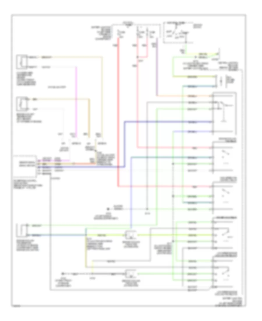
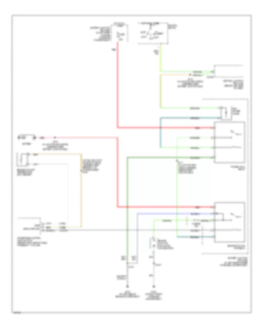
AIR CONDITIONING Heater Wiring Diagram for Ford Focus SVT 2004 List of elements for Heater Wiring Diagram for Ford Focus SVT 2004: 44 (at left ``a" pillar) g204 (at right ``a" pillar) g203 (in main wiring (in main wiring harness, near breakout for instrument cluster) s224 (not used) 15-fa13 29-fa13 29s-le10 31s-fa26 31s-hb22 31s-hb31 32-fa76 33-fa76 91-fa13 91s-fa20 Battery junction box (bjb) (in left rear corner of engine compartment) Blower motor resistor (behind center of dash) C270a C270e Central junction box (cjb) (behind left side of dash) Defogger system Fuse 40a Fuse 7.5a Harness, near breakout for instrument cluster) s212 Heater blower motor (behind center of dash) Heater blower switch Heater control module (behind dash) High Hot at all times Hot in start or run Interior lights system Low speed Medium high Medium low Off Rear window heater on Rear window heater switch Rear window heater switch illumination Recirculation air actuator (behind right side of dash, next to blower motor) Recirculation on Recirculation switch Recirculation switch illumination S249 (in main wiring harness, near breakout for c213) Solid state
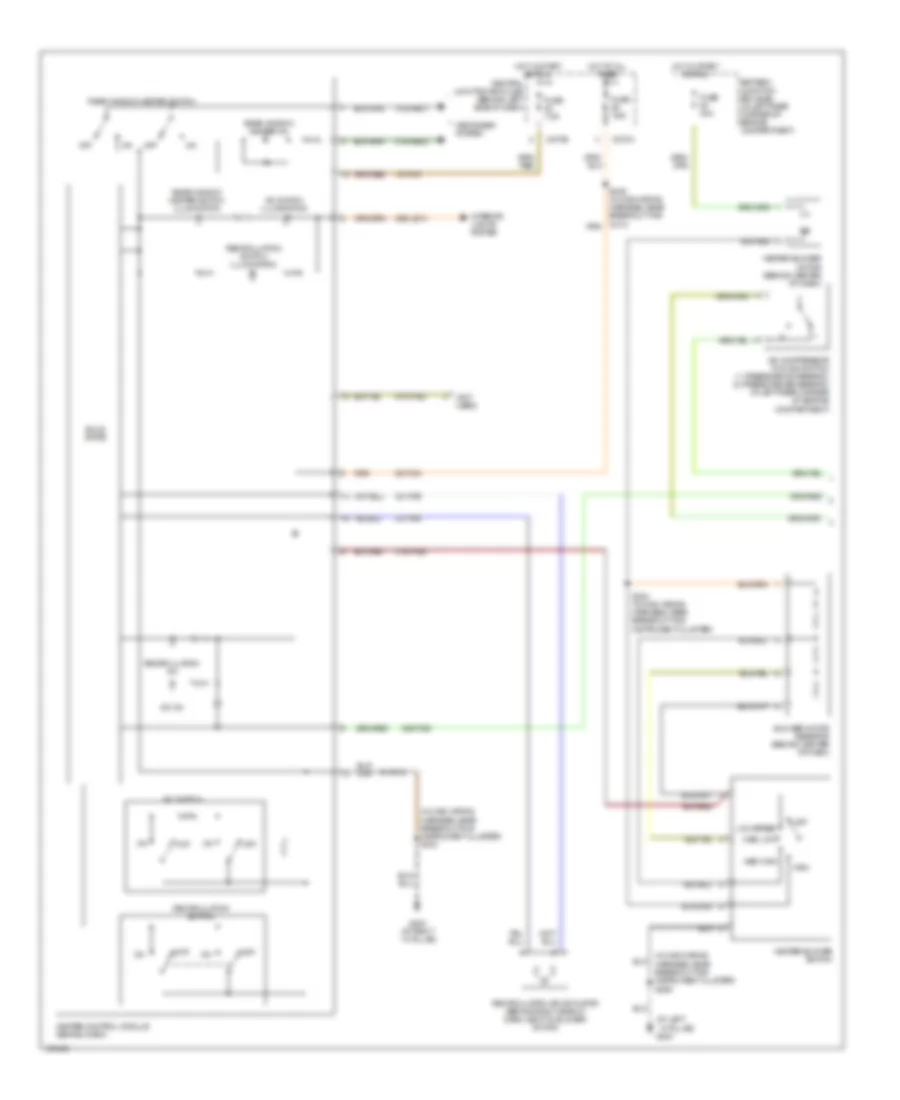
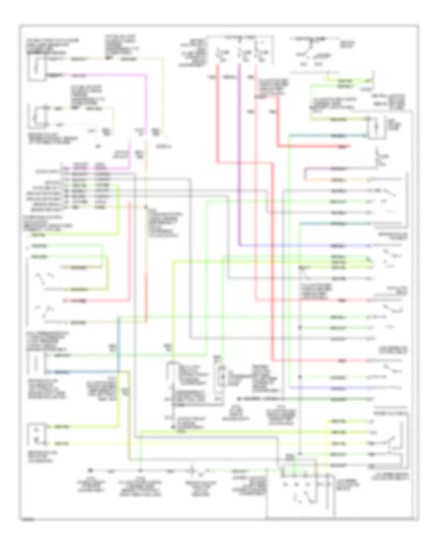
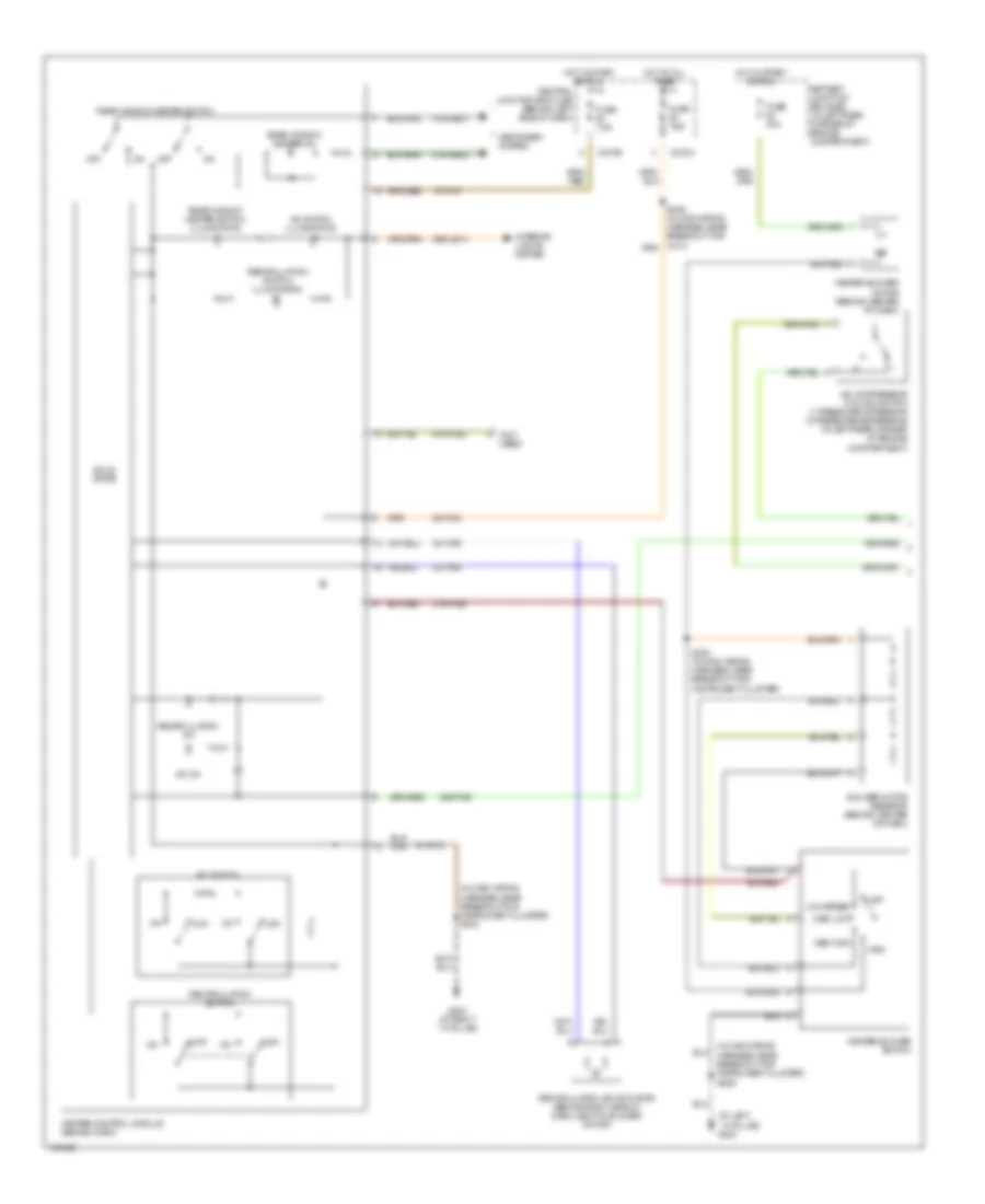
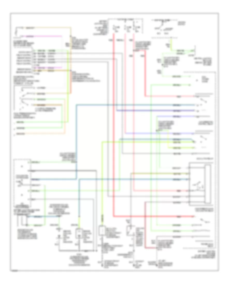
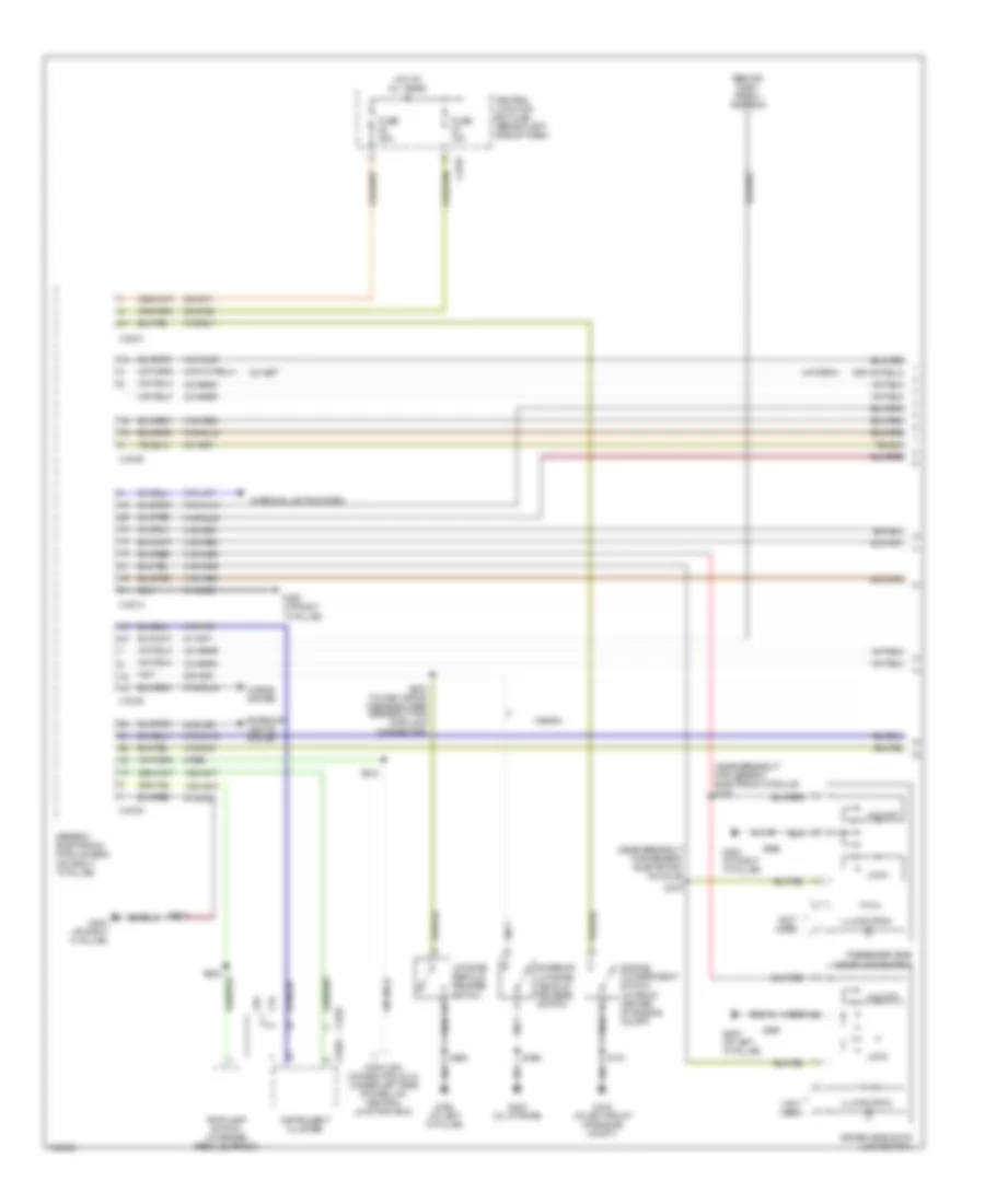
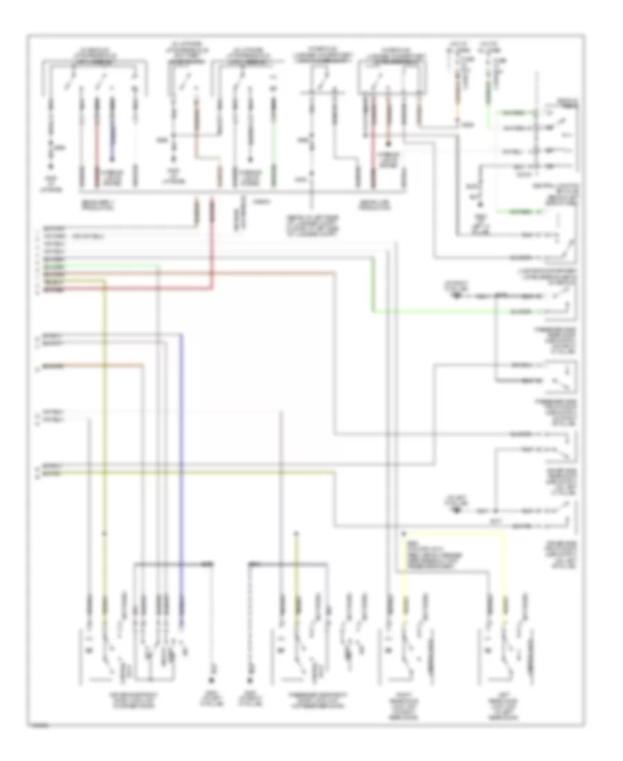
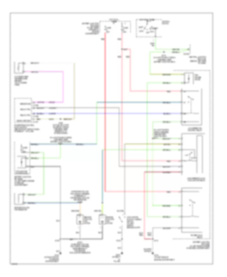
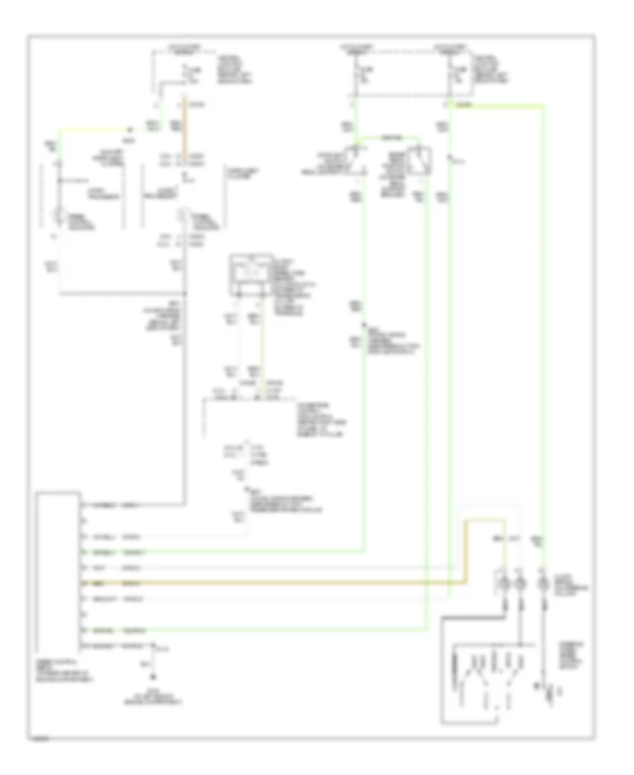
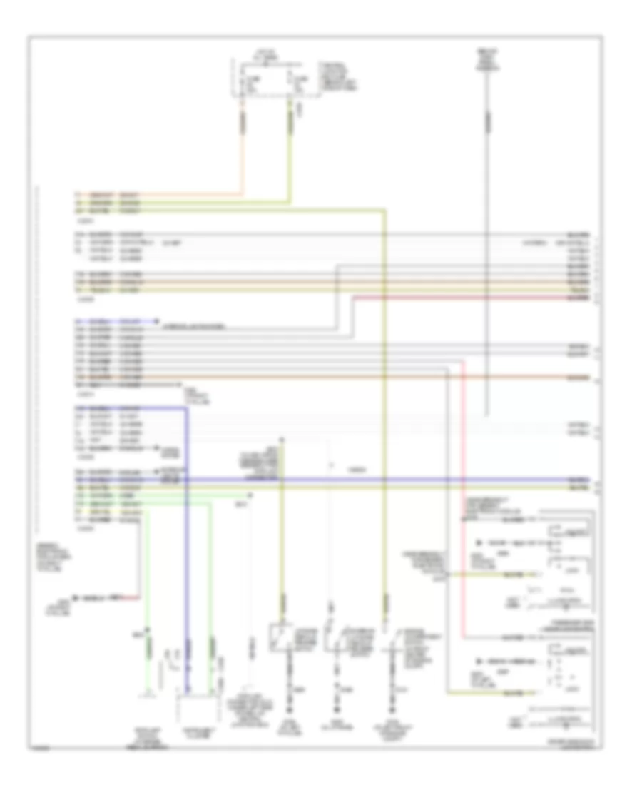
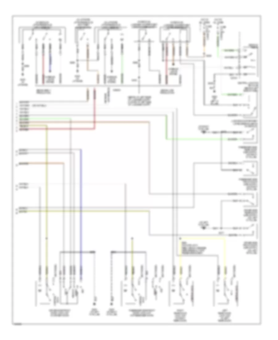
2.0L 2.0L, Manual A/C Wiring Diagram, Except SVT (1 of 2) for Ford Focus SVT 2004 List of elements for 2.0L, Manual A/C Wiring Diagram, Except SVT (1 of 2) for Ford Focus SVT 2004: 49 (at left ``a" pillar) g204 (in main wiring (in main wiring harness, near breakout for instrument cluster) s212 (not used) 15-fa13 15s-fa38 29-fa13 29s-le10 31s-fa26 31s-hb22 31s-hb31 32-fa76 33-fa76 91-fa13 91s-fa20 A/c compressor cycling switch (1: pressure increasing) (2: pressure decreasing) (in left rear corner of engine compartment) A/c on A/c switch A/c switch illumination Battery junction box (bjb) (in left rear corner of engine compartment) Blower motor resistor (behind center of dash) C270a C270e Central junction box (cjb) (behind left side of dash) Defogger system Fuse 40a Fuse 7.5a G203 (at right ``a" pillar) Harness, near breakout for instrument cluster) s206 Heater blower motor (behind center of dash) Heater blower switch Heater control module (behind dash) High Hot at all times Hot in start or run Interior lights system Low speed Med high Med low Off Rear window heater on Rear window heater switch Rear window heater switch illumination Recirculation air actuator (behind right side of dash, next to blower motor) Recirculation on Recirculation switch Recirculation switch illumination S224 (in main wiring harness, near breakout for instrument cluster) Solid state 2.0L, Manual A/C Wiring Diagram, Except SVT (2 of 2) for Ford Focus SVT 2004 List of elements for 2.0L, Manual A/C Wiring Diagram, Except SVT (2 of 2) for Ford Focus SVT 2004: 64 (at right front of engine compartment) g102 (in fuel shutoff solenoid wiring harness, near breakout to intake system) s198 (in junction box wiring harness, (in junction box wiring harness, near battery junction box) s119 (in junction box wiring harness, near battery junction box) (near breakout for right front park/turn lamp) (on right front of cylinder head, near generator) cylinder head temperature sensor 15s-re8 31s-fa11 31s-pa17 31s-pa21 31s-pa7 8-pa13 8-rj5 8-rj33 87a 9-re8 A/c clutch field coil (at right front of engine compartment) A/c clutch relay A/c compressor clutch diode Acc Battery junction box (bjb) (in left rear corner of engine compartment) C270e Central junction box (cjb) (behind left side of dash) Cycling switch) Dual pressure switch 1) normal pressure 2) high pressure (at right side of engine compartment) Engine coolant temperature (ect) sensor (at top rear of engine) Engine cooling fan motor (on radiator) Engine cooling fan relay Engine cooling fan resistor (svt: in front of engine compt, near engine cooling fan) Fuse 10a Fuse 20a Fuse 30a Fuse 50a G102 (at right front of engine compartment) G103 (at left side of engine compt) Ground Ground switched High speed fan control relay Hot at all times Ignition switch Low speed cooling fan relay b Low speed engine cooling fan relay a Nca Near battery junction box) s107 Off Pcm power diode Power hold relay Powertrain control module (pcm) (behind right side of dash, at base of ``a" pillar) Red Run S109 S109 (in junction box wiring harness, near breakout for right front park/turn lamp) S117 S118 (in junction box wiring harness, near battery junction box) S137 (in junction box wiring harness, near breakout for left front side lamp) S163 (in engine control wiring harness, near breakout for a/c compressor Second cooling fan motor (svt: on radiator) Sensor return Sensor signal Spi Start Switch input Switched volt Zetec-e 2.0L, Manual A/C Wiring Diagram, SVT (1 of 2) for Ford Focus SVT 2004 List of elements for 2.0L, Manual A/C Wiring Diagram, SVT (1 of 2) for Ford Focus SVT 2004: 51 (at left ``a" pillar) g204 (in main wiring (not used) 15-fa13 15s-fa38 29-fa13 29s-le10 31s-fa26 31s-hb22 31s-hb31 32-fa76 33-fa76 91-fa13 91s-fa20 A/c compressor cycling switch 1) pressure increasing 2) pressure decreasing (in left rear corner of engine compartment) A/c on A/c switch A/c switch illumination Battery junction box (bjb) (in left rear corner of engine compartment) Blower motor resistor (behind center of dash) C270a C270e Central junction box (cjb) (behind left side of dash) Defogger system Fuse 40a Fuse 7.5a G203 (at right ``a" pillar) Harness, near breakout for instrument cluster) s206 Harness, near breakout for instrument cluster) s212 Harness, near breakout for instrument cluster) Heater blower motor (behind center of dash) Heater blower switch Heater control module (behind dash) High Hot at all times Hot in run or start Hot in start or run Interior lights system Low Med high Med low Off Rear window heater on Rear window heater switch Rear window heater switch illumination Recirculation air actuator (behind right side of dash, next to blower motor) Recirculation on Recirculation switch Recirculation switch illumination S224 (in main wiring Solid state 2.0L, Manual A/C Wiring Diagram, SVT (2 of 2) for Ford Focus SVT 2004 List of elements for 2.0L, Manual A/C Wiring Diagram, SVT (2 of 2) for Ford Focus SVT 2004: 49 (in fuel shutoff solenoid wiring harness, near breakout to intake system) s198 (in junction box wiring harness near battery junction box) s102 (in junction box wiring harness near battery junction box) s117 (in junction box wiring harness near battery junction box) s119 (in junction box wiring harness, near battery junction box) s118 (in junction box wiring (in left rear corner of engine compartment) battery junction box (bjb) 15s-re8 31s-fa11 31s-pa7 8-pa13 8-rj5 9-re8 A/c clutch field coil (at right front of engine compartment) A/c clutch relay A/c compressor clutch diode Acc Battery (in left side of engine compt) Battery junction box (bjb) (in left rear corner of engine compartment) Breakout for right C270e Central junction box (cjb) (behind left side of dash) Dual pressure switch 1) normal pressure 2) high pressure (at right side of engine compartment) Engine coolant temperature (ect) sensor (at top rear of engine) Engine cooling fan resistor) Engine cooling fan motor (on radiator) Engine cooling fan relay Front park/turn lamp) Fuse 10a Fuse 20a Fuse 30a G102 (at right front of engine compartment) G103 (at left side of engine compartment) Ground switched Hot at all times Ignition switch Lock Pcm power diode Power hold relay Powertrain control module (pcm) (behind right side of dash, at base of "a" pillar) Red Run off S1001 (in engine cooling fan S109 S163 (in engine control wiring harness, near breakout for a/c compressor cycling switch) Sensor return Sensor signal Start Switched volt
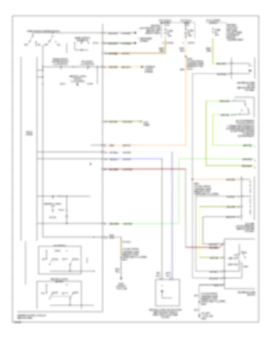
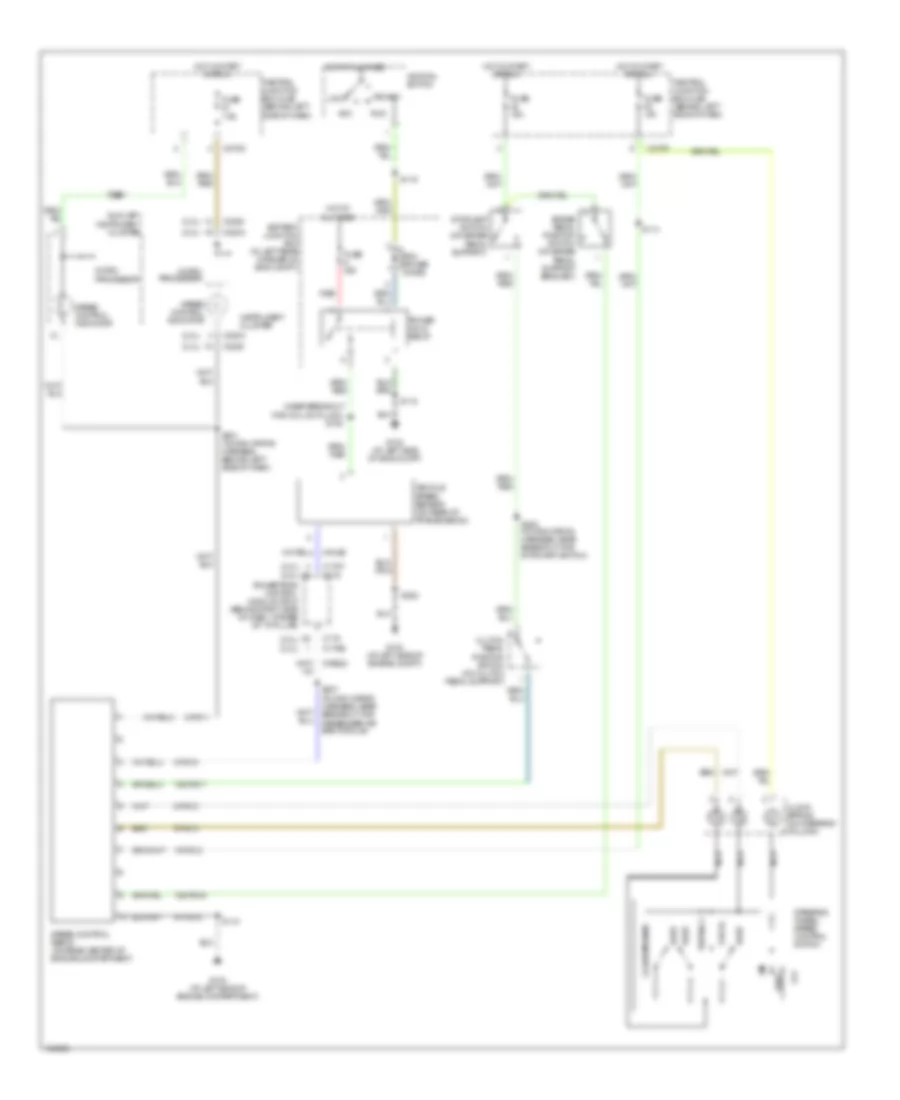
2.3L 2.3L, Manual A/C Wiring Diagram (1 of 2) for Ford Focus SVT 2004 List of elements for 2.3L, Manual A/C Wiring Diagram (1 of 2) for Ford Focus SVT 2004: 49 (at left ``a" pillar) g204 (in main wiring (in main wiring harness, near breakout for instrument cluster) s212 (not used) 15-fa13 15s-fa38 29-fa13 29s-le10 31s-fa26 31s-hb22 31s-hb31 32-fa76 33-fa76 91-fa13 91s-fa20 A/c compressor cycling switch 1) pressure increasing 2) pressure decreasing (in left rear corner of engine compartment) A/c on A/c switch A/c switch illumination Battery junction box (bjb) (in left rear corner of engine compartment) Blower motor resistor (behind center of dash) C270a C270e Central junction box (cjb) (behind left side of dash) Defogger system Fuse 40a Fuse 7.5a G203 (at right ``a" pillar) Harness, near breakout for instrument cluster) s206 Heater blower motor (behind center of dash) Heater blower switch Heater control module (behind dash) High Hot at all times Hot in start or run Interior lights system Low speed Med high Med low Off Rear window heater on Rear window heater switch Rear window heater switch illumination Recirculation air actuator (behind right side of dash, next to blower motor) Recirculation on Recirculation switch Recirculation switch illumination S224 (in main wiring harness, near breakout for instrument cluster) Solid state 2.3L, Manual A/C Wiring Diagram (2 of 2) for Ford Focus SVT 2004 List of elements for 2.3L, Manual A/C Wiring Diagram (2 of 2) for Ford Focus SVT 2004: 60 (1: normal pressure) (2: high pressure) (at left (at right front of engine compartment) g102 (at right ``a" pillar) g202 (in engine cooling fan wiring harness, at breakout for engine cooling fan resistor) s1002 (in junction box wiring harness, near battery junction box) s107 (in junction box wiring harness, near battery junction box) s108 (in junction box wiring harness, near battery junction box) s117 (in junction box wiring harness, near battery junction box) s118 (in junction box wiring harness, near battery junction box) s119 (near breakout for right front park/ turn lamp) s109 15s-re8 31s-fa11 31s-pa17 31s-pa7 8-pa13 8-rj33 9-rj33 A/c clutch field coil (at right front of engine compartment) A/c clutch relay A/c compressor clutch diode Acc Battery junction box (bjb) (in left rear corner of engine compartment) Battery junction box (bjb) (in left rear corner of engine compt) C175b C175e C270e Central junction box (cjb) (behind left side of dash) Compressor cycling switch) Cooling fan motor diode Cooling fan run-on thermo switch (at left side of engine compt) Cylinder head temperature sensor (on cylinder head) Dual pressure switch (at right side of engine compartment) Engine cooling fan motor (on radiator) Engine cooling fan resistor (in front of engine compartment, near engine cooling fan) Fuse 10a Fuse 20a Fuse 30a Fuse 50a High speed run-on cooling fan relay Hot at all times Ignition switch Low speed fan control relay Off Pcm power diode Power hold relay Powertrain control module (pcm) (behind right side of dash, at base of ``a" pillar) Red Relay control Run S1001 (in engine cooling fan wiring harness near breakout for engine cooling fan resistor) S162 (in engine control wiring harness, near breakout for a/c S198 (in fuel shut-off solenoid wiring harness, near breakout to intake system) S279 (near breakout for c211) Second cooling fan motor (on radiator) Sensor return Sensor signal Side of engine compartment) g103 Start Switch input
ANTI-LOCK BRAKES Anti-lock Brakes Wiring Diagram, with Traction Control for Ford Focus SVT 2004 List of elements for Anti-lock Brakes Wiring Diagram, with Traction Control for Ford Focus SVT 2004: 69 (at left front of engine compt) g101 1. tcs enable, disable 15-cf6a 15s-cf58 2. rest 3. illumination 30-cf13a 30-cf6a 31s-cf28 31s-cf45 31s-cf45a 4-eg6 5-eg6 8-cf32 8-cf34 8-cf38 8-cf40 8-ee6a 9-cf32 9-cf34 9-cf38 9-cf40 91-cf13 91-cf6 91s-cf54 Abs control module (in left rear corner of engine compartment, under master cylinder) Abs indicator Abs test connector (in left side of engine compt) Battery junction box (bjb) (in left rear corner of engine compt) Brake ind Brake pedal position switch (on brake pedal support bracket) C220a C270d C270f Central junction box (cjb) (behind left side of dash) Computer data lines system Ctrl Fuse 15a Fuse 20a Fuse 30a Fuse 7.5a G203 (at right "a" pillar) Gnd Hot at all times Hot in start or run Instrument cluster Interior lights system Iso Left front wheel speed sensor (on left front wheel hub) Left rear wheel speed sensor (on left rear wheel hub) Micro- processor Nca Red Right front wheel speed sensor (on right front wheel hub) Right rear wheel speed sensor (on right rear wheel hub) S141 S202 (in main S212 Scp+ Scp- Sig Stoplamp switch (on brake pedal support) Sw in Traction control ind Traction control system (tcs) disable switch Twisted pair Vbatt Vpwr Wiring harness, near breakout for stoplamp switch) Anti-lock Brakes Wiring Diagram, without Traction Control for Ford Focus SVT 2004 List of elements for Anti-lock Brakes Wiring Diagram, without Traction Control for Ford Focus SVT 2004: 62 (at left front of engine compt) g101 (in left side of engine compt) 15-cf6a 15s-cf58 2.0l 2.3l 30-cf13a 30-cf6a 31s-cf28 31s-cf45 4-eg6 5-eg6 8-cf32 8-cf34 8-cf38 8-cf40 8-ee6a 9-cf32 9-cf34 9-cf38 9-cf40 91-cf13 91-cf6 Abs control module (in left rear corner of engine compartment, under master cylinder) Abs indicator Abs test connector Battery junction box (bjb) (in left rear corner of engine compt) Brake ind Brake pedal position switch (on brake pedal support bracket) C220a C2220 C270d C270f Central junction box (cjb) (behind left side of dash) Computer data lines system Ctrl Fuse 15a Fuse 20a Fuse 30a Fuse 7.5a Gnd Hot at all times Hot in start or run Instrument cluster Iso Left front wheel speed sensor (on left front wheel hub) Left rear wheel speed sensor (on left rear wheel hub) Micro- processor Nca Red Right front wheel speed sensor (on right front wheel hub) Right rear wheel speed sensor (on right rear wheel hub) S141 S202 (in main Scp+ Scp- Stoplamp switch (on brake pedal support) Sw in Twisted pair Vbatt Vpwr Wiring harness, near breakout for stoplamp switch)
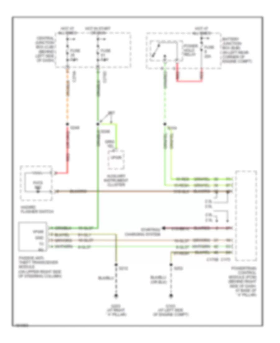
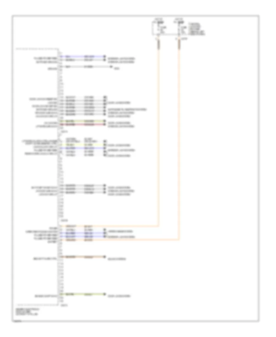
ANTI-THEFT Forced Entry Wiring Diagram (1 of 2) for Ford Focus SVT 2004 List of elements for Forced Entry Wiring Diagram (1 of 2) for Ford Focus SVT 2004: 82 (behind dash panel) antenna (near breakout for generic electronic module) (not used) 15s-aa17 15s-aa72 2.0l 2.3l 29-aa17 29-dk20 31-dk20 31s-aa39 31s-aa61 31s-aa62 31s-aa63 31s-aa64 31s-aa7 31s-aa85 31s-gl12 31s-gl16 31s-gl19 31s-gl20 31s-gl27 31s-gl7 31s-gl9 31s-lc7 32-aa27 32-aa59a 32-aa59b 32-aa59c 32-aa59d 33-aa59 8-ee9 8s-aa30 91-aa17 91-dk20 91s-gl43 91s-lg8 C201a C201b C201c C201d C201e C220a C2220 C270f Central junction box (cjb) (behind left side of dash) Data link connector (dlc) (under left side of dash, on central junction box) Driver side door lock switch Engine compartment switch (in front center of engine compt) Exterior liftgate/ decklid release switch Exterior lights system Fuse 15a Fuse 20a G100 (at left front of engine compt) G200 (at left "a" pillar) G203 (at right "a" pillar) G204 (at left "a" pillar) G300 (at right "a" pillar) G400 (in liftgate) Generic electronic module (gem) (on right "a" pillar) Horns system Hot at all times Illumination Instrument cluster Interior lights system Liftgate/ decklid release switch Lock Passenger side door lock switch S121 S202 S206 S210 S212 S230 (in main wiring harness, near breakout for data link connector) S375 S376 S496 S597 S694 Stoplamp switch (on brake pedal support) Unlock Wagon Forced Entry Wiring Diagram (2 of 2) for Ford Focus SVT 2004 List of elements for Forced Entry Wiring Diagram (2 of 2) for Ford Focus SVT 2004: 50 (at left "a" pillar) g200 (at right "a" pillar) g300 (in decklid) liftgate/decklid latch assembly (in decklid) luggage compartment lid release relay (in decklid) luggage compartment lock cylinder switch (in liftgate) liftgate/decklid anti-theft inhibit switch (in liftgate) liftgate/decklid latch assembly (not used) (sedan: at left rear of luggage compt) (3-door: at left side of luggage compt) C270a C270b C270h Central Central junction box (cjb) (behind left side of dash) Central lock Decklid relay Driver side front door ajar switch (on left "b" pillar) Driver side front door lock unit (in driver door) Driver side rear door ajar switch (on left "c" pillar) Fuse 20a Fuse 25a G200 (at left "a" pillar) G204 (at left "a" pillar) G300 (at right "a" pillar) G400 (in liftgate) G402 Hot at all times Interior lights system Left rear door lock unit (in left rear door) Lock Luggage compartment lid release solenoid (in decklid) Nca Passenger side front door ajar switch (on right "b" pillar) Passenger side front door lock unit (in passenger door) Passenger side rear door ajar switch (on right "c" pillar) Reset Right rear door lock unit (in right rear door) S206 S259 S360 (in door lock feed wiring harness, near breakout for passenger's seat) S377 S378 S496 S597 S694 Sedan early production Sedan late production Set Unlock Wagon Passive Anti-theft Wiring Diagram for Ford Focus SVT 2004 List of elements for Passive Anti-theft Wiring Diagram for Ford Focus SVT 2004: 39 10-gl37 15-gl37 15-re8 15-re8a 2.0l 2.3l 31s-bb16 31s-gl6 8-gl37 91-gl1 91-re8a Auxiliary instrument cluster Battery junction box (bjb) (in left rear corner of engine compt) C175 C175b C270a C270d Central junction box (cjb) (behind left side of dash) Fuse 20a Fuse 7.5a G103 (at left side of engine compt) G203 (at right ``a" pillar) Gnd Hazard flasher switch Hot at all times Hot in start or run Passive anti- theft transceiver module (on upper right side of steering column) Pats ind Power hold relay Powertrain control module (pcm) (behind right side of dash, at base of ``a" pillar) Red S154 S212 S248 S249 S252 Starting/ charging system Svt Vpwr
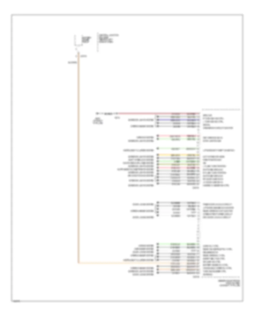
BODY CONTROL MODULES Body Control Modules Wiring Diagram (1 of 2) for Ford Focus SVT 2004 List of elements for Body Control Modules Wiring Diagram (1 of 2) for Ford Focus SVT 2004: 62 29-aa17 29-dk20 31-dk20 31s-aa39 31s-aa61 31s-aa62 31s-aa63 31s-aa64 31s-aa85 31s-ge52 31s-gl12 31s-gl19 31s-gl20 31s-gl27 31s-gl5 31s-gl7 31s-lc7 32-aa27 (or 32-aa51) 32-aa59c 32-aa59d 32-ka9a 33-aa59 49s-lg12 49s-lg19 49s-lg4 49s-lg5 Anti-theft inhibit sw in Battery C201a C201b C201c C270f Central junction box (bjb) (behind left side of dash) Door lock sw reset sig Door lock sw set sig Door locks system Engine compt sw in Exterior lights system Fuse 15a Fuse 20a G302 Generic electronic module (gem) (on right "a" pillar) Ground Hot at all times Interior lights system Liftgate ajar sw in Liftgate unlatch mtr/luggage compt lid release sol ctrl Lock sig Lock sw circuit Lock/unlock circuit Lr door ajar sw in Power Pulsed power feed Rear doors lk/unlk circuit Rr door ajar sw in Security alarm ctrl Sound systems Switched ground Unlock sig Unlock sw circuit Wiper park pos sig monitor Wiper/washer system Body Control Modules Wiring Diagram (2 of 2) for Ford Focus SVT 2004 List of elements for Body Control Modules Wiring Diagram (2 of 2) for Ford Focus SVT 2004: 84 15s-aa17 15s-aa72 29s-le18 29s-lg43 30s-ta31a 31s-aa7 31s-ge49 31s-gl16 31s-gl9 31s-hb20 31s-hb22 31s-lc22 31s-ta32 32-aa59a 32-aa59b 32-ka35 32-ka6 33-ka6 49s-lg15 49s-lg22 8-ee9 8-ka18 8-ka19 83-aa30 91-aa17 91-dk20 91s-gl43 91s-ja13 91s-ka12 91s-ka29 91s-lg1 91s-lg2 91s-lg8 Air conditioning system Antenna Battery saver relay Battery saver rly ctrl C201d C201e C270a Central junction box (bjb) (behind left side of dash) Computer data lines system Defogger system Door locks system Dr ajar ind ctrl Drv door lk/unlk circuit Exterior lights system G203 (at right "a" pillar) Generic electronic module (gem) (on right "a" pillar) Ground Hazard flasher sw ctrl Horn rly ctrl Horns system Hot in park or head Instrument cluster system Interior lights system Intermittent wiper circuit Iso Key warning sw in L flash turn portion L turn sig ind ctrl Lf door ajar sw in Liftgate anti-theft inhibit sw Liftgate washer sw monitor Park position sw Pass door lk/unlk circuit R flash turn portion R turn sig ind ctrl Rear win defrost rly ctrl Rear wiper rly ctrl Rear wiper sw ckt monitor Release sw in Rf door ajar sw in S212 Safety belt ind ctrl Shift interlock system Signal Stop lamp sw sig Switched ground Turn sig buzzer ctrl Warning system Washer sw circuit monitor Windshield wiper rly ctrl Wiper/washer system
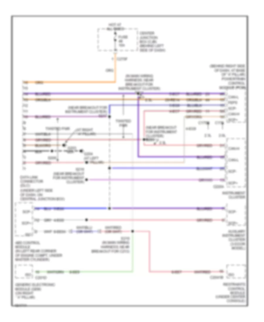
COMPUTER DATA LINES Computer Data Lines Wiring Diagram for Ford Focus SVT 2004 List of elements for Computer Data Lines Wiring Diagram for Ford Focus SVT 2004: 44 (at right ``a" pillar) (behind right side of dash, at base of "a" pillar) powertrain control module (pcm) (in main wiring harness, near breakout for instrument cluster) s211 (near breakout for instrument cluster) s217 (near breakout for instrument cluster) s293 (under left side of dash, on central junction box) 2.0l 2.3l 29-re14 4-ec7 4-eg6 4-eg9 5-ec7 5-eg6 5-eg9 8-ee6a 8-ee7 8-ee9 Abs control module (in left rear corner of engine compt, under master cylinder) Auxiliary instrument cluster (3-door model) C175 C175b C201d C2041b C220a C270f Can-h Can-l Center junction box (cjb) (behind left side of dash) Data link connector (dlc) Feps Fuse 10a G204 (at left ``a" pillar) Generic electronic module (gem) (on right ``a" pillar) Hot at all times Instrument cluster Iso Restraints control module (under center console) S206 S210 (in main wiring harness, near breakout for c213) S216 (near breakout for instrument cluster) Scp+ Scp- Twisted pair
COOLING FAN
2.0L 2.0L, Cooling Fan Wiring Diagram, Except SVT for Ford Focus SVT 2004 List of elements for 2.0L, Cooling Fan Wiring Diagram, Except SVT for Ford Focus SVT 2004: 49 (at left side of engine compartment) (in fuel shutoff 31s-pa17 31s-pa21 31s-pa7 8-rj5 8-rj33 87a 9-re8 Acc Battery junction box (bjb) (in left rear corner of engine compartment) C270e Central junction box (cjb) (behind left side of dash) Cylinder head temperature sensor (on right front of cylinder head, near generator) Engine coolant temperature (ect) sensor (at top rear of engine) Engine cooling fan motor (on radiator) Engine cooling fan relay Engine cooling fan resistor (in front of engine compartment, near engine cooling fan) Fuse 20a Fuse 30a Fuse 50a G102 (at right front G103 Harness, near breakout for left front side lamp) High speed fan control relay Hot at all times Ignition switch Lock Low speed engine cooling fan relay a Low speed engine cooling fan relay b Nca Of engine compartment) Pcm power diode Power hold relay Powertrain control module (pcm) (behind right side of dash, at base of ``a" pillar) Red Run off S107 S109 S117 (in junction box wiring harness, near battery junction box) S118 S119 (in junction box wiring harness, near battery junction box) S137 (in junction box wiring S198 (in fuel shutoff solenoid wiring harness, near breakout to intake system) Second cooling fan motor (on radiator) Sensor signal Signal return Spi Start Zetec-e 2.0L, Cooling Fan Wiring Diagram, SVT for Ford Focus SVT 2004 List of elements for 2.0L, Cooling Fan Wiring Diagram, SVT for Ford Focus SVT 2004: 33 (in fuel shut-off solenoid wiring harness, near breakout to intake system) s198 (in junction box wiring harness, near battery junction box) 31s-pa7 8-rj5 9-re8 Acc Battery Battery junction box (bjb) (in left rear corner of engine compartment) C270e Central junction box (cjb) (behind left side of dash) Engine coolant temperature (ect) sensor Engine cooling fan motor (on radiator) Engine cooling fan relay Fuse 20a Fuse 65 30a G102 (at right front of engine compartment) G103 (at left side of engine compartment) Hot at all times Ignition switch Lock Pcm power diode Power hold relay Powertrain control module (pcm) (behind right side of dash, at base of ``a" pillar) Red Run off S1001 S102 S117 (in junction box wiring harness, near battery junction box) S118 S119 (in junction box wiring harness, near battery junction box) Signal return Start Vref
2.3L 2.3L, Cooling Fan Wiring Diagram for Ford Focus SVT 2004 List of elements for 2.3L, Cooling Fan Wiring Diagram for Ford Focus SVT 2004: 50 (at right (in engine cooling fan wiring harness, at breakout for engine cooling fan resistor) s1002 (in junction box wiring harness, near battery junction box) s108 (in junction box wiring harness, near battery junction box) s117 31s-pa17 31s-pa7 8-rj33 9-da1 Acc Battery junction box (bjb) (in left rear corner of engine compartment) C175b C175e C175t C270e Central junction box (cjb) (behind left side of dash) Cooling fan motor diode Cooling fan run-on thermo switch (at left side of engine compt) Cylinder head temperature sensor (on cylinder head) Engine compartment) Engine cooling fan motor Engine cooling fan resistor Fuse 20a Fuse 30a Fuse 50a G102 (at right front of engine compartment) G103 (at left side of G202 High speed run-on cooling fan relay Hot at all times Ignition switch Lock Low speed fan control relay Pcm power diode Power hold relay Powertrain control module (pcm) (behind right side of dash, at base of ``a" pillar) Red Relay ctrl Run off S1001 (in engine cooling fan wiring harness, near breakout for engine cooling fan resistor) S105 S107 S109 S118 S119 (in junction box wiring harness, near battery junction box) S198 (in fuel shut-off solenoid wiring harness, near breakout to intake system) Second cooling fan motor Sensor sig Signal return Start ``a" pillar)
CRUISE CONTROL Cruise Control Wiring Diagram, A/T for Ford Focus SVT 2004 List of elements for Cruise Control Wiring Diagram, A/T for Ford Focus SVT 2004: 50 (2.0l) (2.3l) (in main wiring harness, behind left side of dash) 15-pg12 15s-pg16 15s-pg17 8-pg11 8-pg13 8-pg18 8-re22 8-rj29 9-pg13 9-rj29 91-pg12 Auxiliary instrument cluster Brake pedal position switch (on brake pedal support bracket) C175 C175b C175t C220a C2220 C270d C270f Central junction box (cjb) (behind left side of dash) Clock spring (on steering column) Coast/resume Decel Fuse 10a Fuse 15a Fuse 7.5a G103 (at left side of engine compartment) Hot in start or run Instrument cluster Micro- processor Nca Off Output shaft speed (oss) sensor (2.0l dohc & 2.3l: on rear of transmission) (2.0l spi: on rear of transaxle) Powertrain control module (pcm) (behind right side of dash, at base of "a" pillar) Rest S114 S118 S202 (in main wiring harness, near breakout for stoplamp switch) S207 (in main wiring harness, near breakout for passenger air bag module) S221 S248 Set/acc Speed control indicator Speed control servo (on rear center of engine compartment) Steering wheel/ speed control switch Stoplamp switch (on brake pedal support) Cruise Control Wiring Diagram, M/T for Ford Focus SVT 2004 List of elements for Cruise Control Wiring Diagram, M/T for Ford Focus SVT 2004: 68 (2.0l) (2.0l) (2.3l) (2.3l) (2.3l) (2.0l) (near breakout for coil on plug 2) 15-pg12 15s-pg16 15s-pg17 8-pg11 8-pg13 8-pg18 8-re22 8-rj29 9-pg13 91-pg12 Acc Auxiliary instrument cluster Battery junction box (in left rear corner of eng compt) Brake pedal position switch (on brake pedal support bracket) C175 C175b C175t c175 C220a C2220 C270d C270f Central junction box (cjb) (behind left side of dash) Clock spring (on steering column) Clutch pedal position switch (on clutch pedal support) Coast/resume Decel Fuse 10a Fuse 15a Fuse 20a Fuse 7.5a G103 (at left side of eng compt) G103 (at left side of engine compartment) G103 (at left side of engine compt) Hot at all times Hot in start or run Ignition switch Instrument cluster Lock Micro- processor Nca Off Pcm power diode Power hold relay Powertrain control module (pcm) (behind right side of dash, at base of "a" pillar) Red Rest Run S114 S118 S119 S154 S202 (in main wiring harness, near breakout for stoplamp switch) S207 (in main wiring harness, near breakout for passenger air bag module) S221 (in main wiring harness, behind left side of dash) S248 S252 Set/acc Speed control indicator Speed control servo (on rear center of engine compartment) Start Steering wheel/ speed control switch Stoplamp switch (on brake pedal support) Vehicle speed sensor (on rear of transmission)
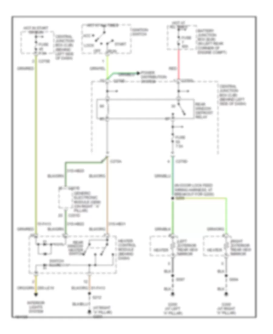
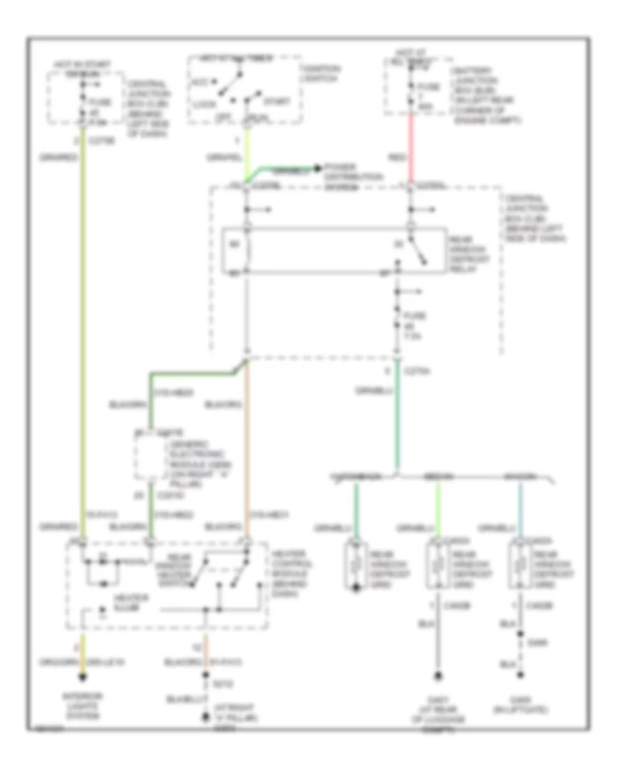
DEFOGGERS Heated Mirrors Wiring Diagram for Ford Focus SVT 2004 List of elements for Heated Mirrors Wiring Diagram for Ford Focus SVT 2004: 41 (at right "a" pillar) g203 (in door lock feed wiring harness, at breakout for g200) 15-fa13 31s-hb20 31s-hb22 31s-hb31 Acc Battery junction box (bjb) (in left rear corner of engine compt) C201d C201e C270a C270d C270e C270g Central junction box (cjb) (behind left side of dash) Fuse 40a Fuse 7.5a G200 (at left "a" pillar) G300 (at right "a" pillar) Generic electronic module (gem) (on right ``a" pillar) Heater Heater control module (behind dash) Hot at all times Hot in start or run Ignition switch Interior lights system Left exterior rear view mirror Lock Off Power distribution system Rear window defrost relay Rear window heater switch Red Right exterior rear view mirror Run S212 S255 S597 S694 Start Switch illum Rear Defogger Wiring Diagram for Ford Focus SVT 2004 List of elements for Rear Defogger Wiring Diagram for Ford Focus SVT 2004: 40 (at right "a" pillar) g203 15-fa13 31s-hb20 31s-hb22 31s-hb31 Acc Battery junction box (bjb) (in left rear corner of engine compt) C201d C201e C270a C270e C270g C402a C402b Central junction box (cjb) (behind left side of dash) Fuse 40a Fuse 7.5a G400 (in liftgate) G401 (at rear of luggage compt) Generic electronic module (gem) (on right ``a" pillar) Hatchback Heater control module (behind dash) Heater illum Hot at all times Hot in start or run Ignition switch Interior lights system Lock Off Power distribution system Rear window defrost grid Rear window defrost relay Rear window heater switch Red Run S212 S496 Sedan Start Wagon
ENGINE PERFORMANCE
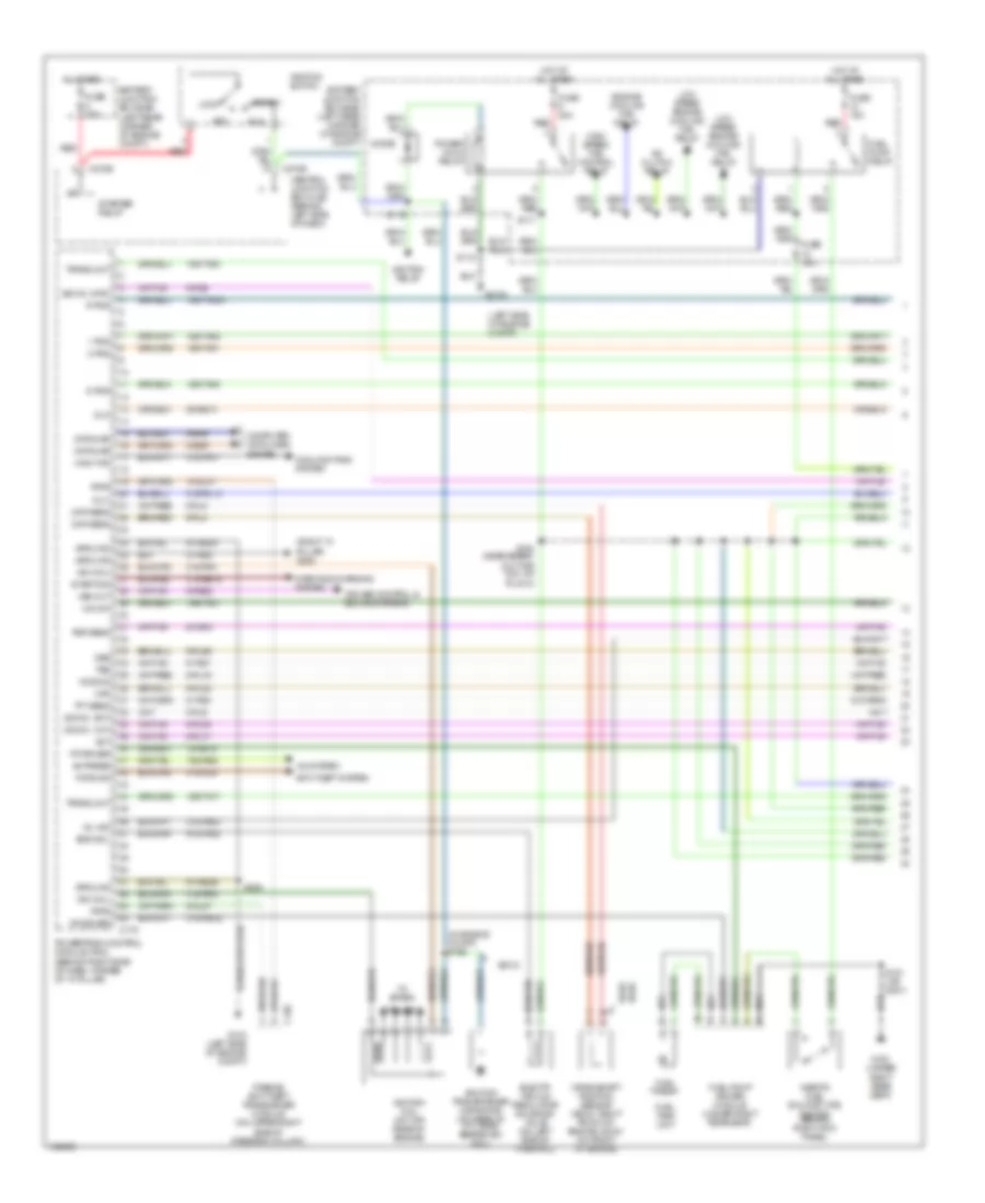
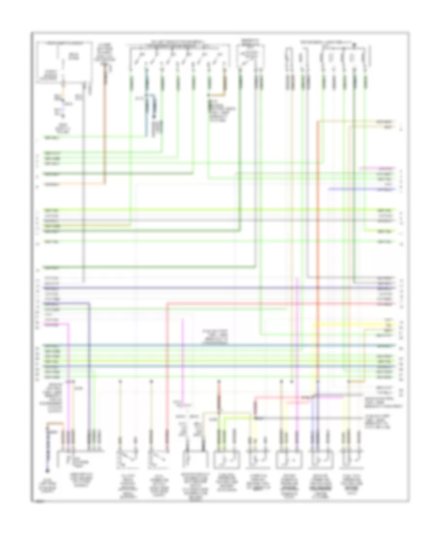
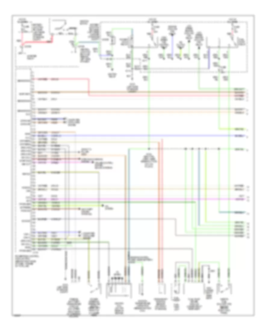
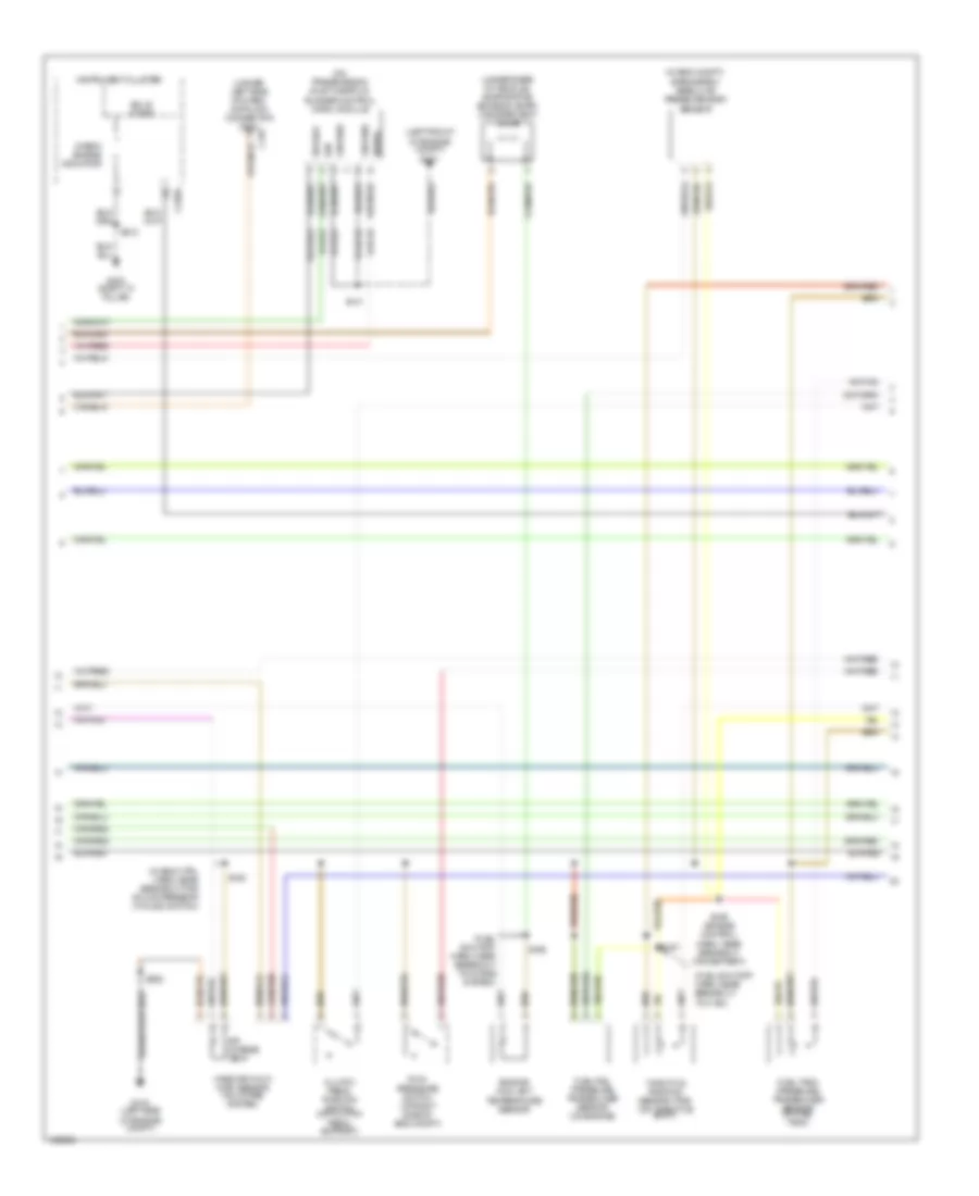
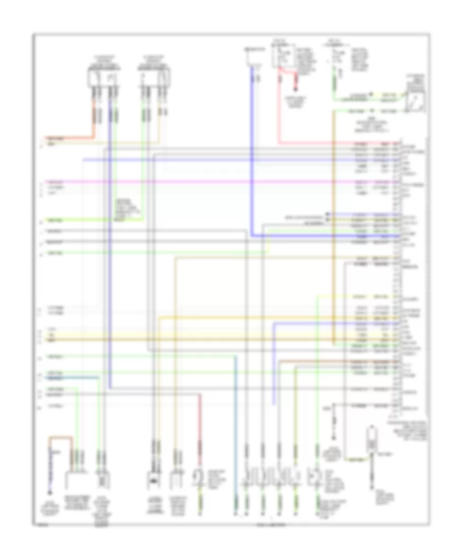
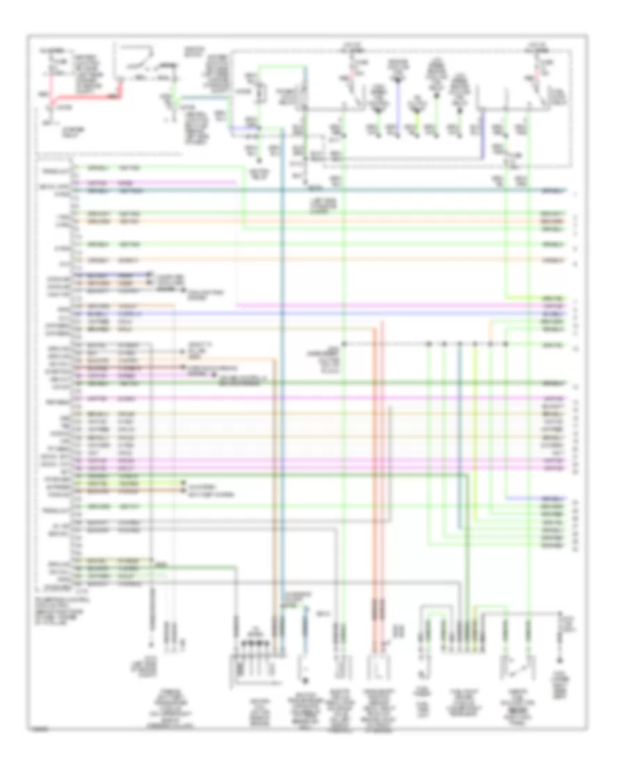
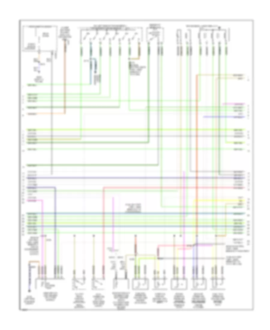
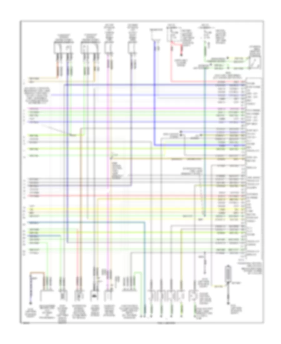
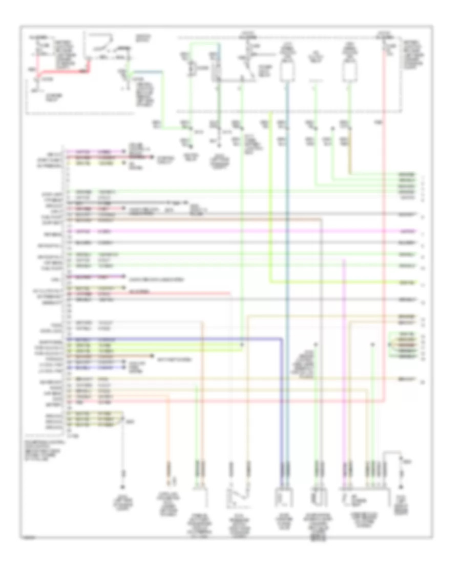
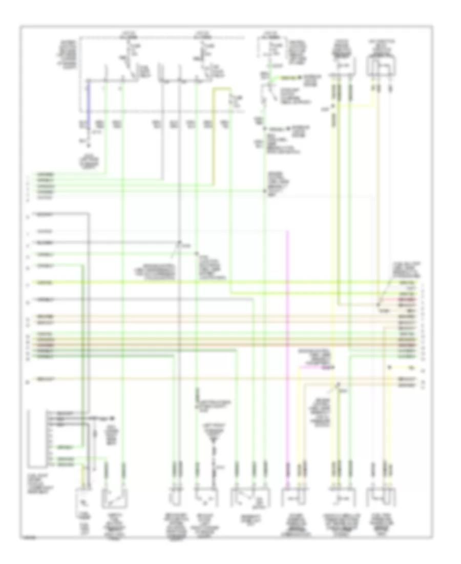
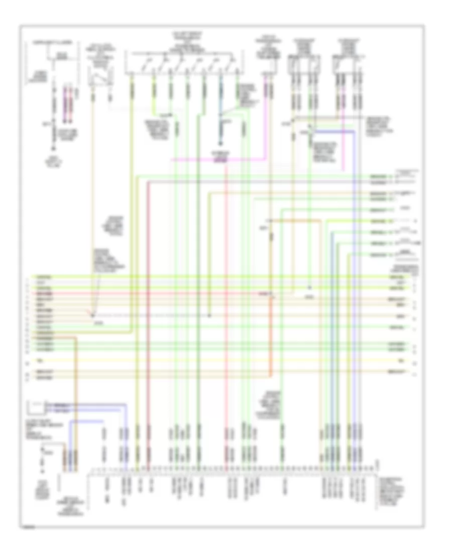
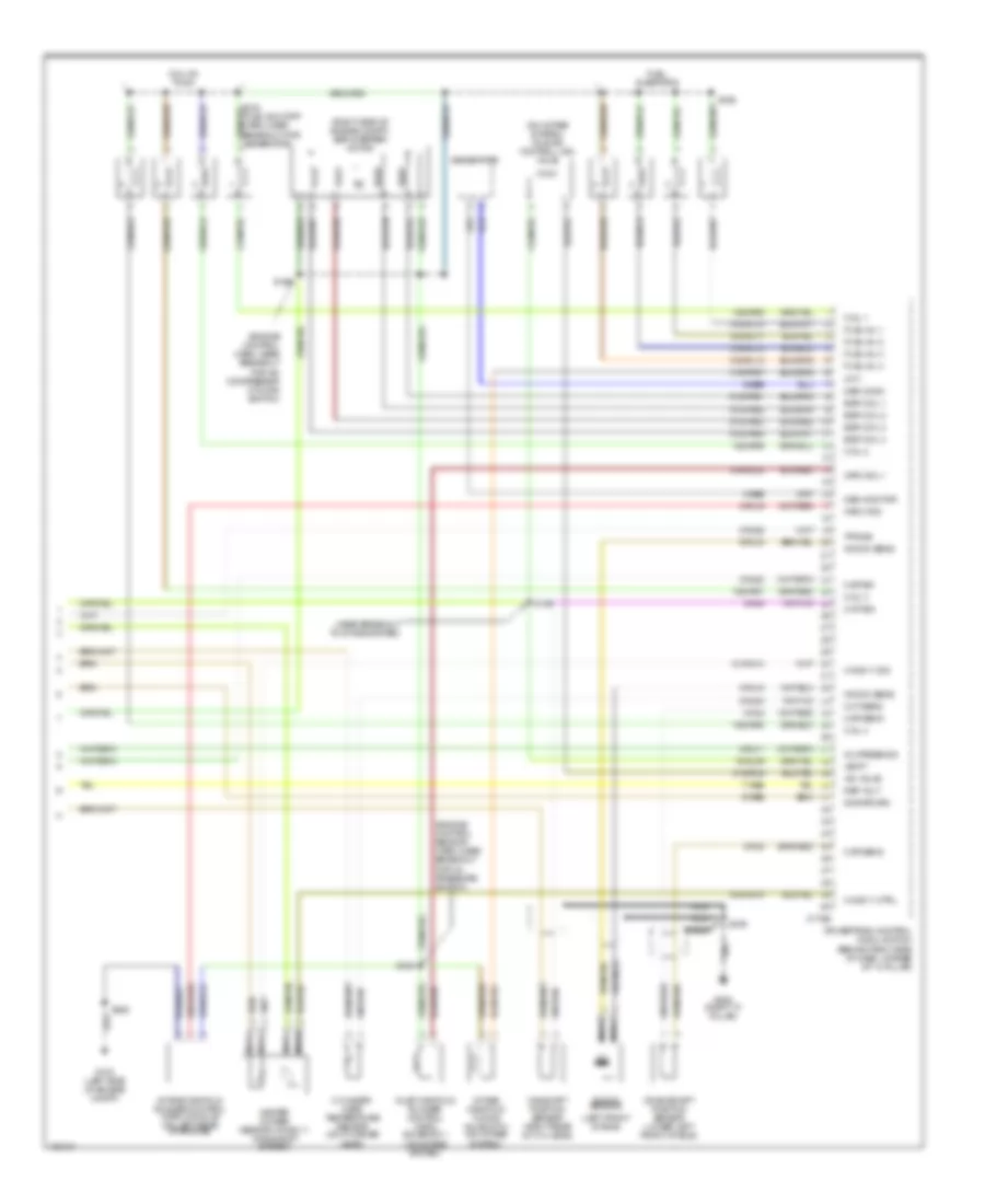
2.0L DOHC 2.0L DOHC, Engine Performance Wiring Diagram, Except SVT (2 of 3) for Ford Focus SVT 2004 List of elements for 2.0L DOHC, Engine Performance Wiring Diagram, Except SVT (2 of 3) for Ford Focus SVT 2004: 36 (a/t) (engine control harn, near breakout for a/c compressor cycling switch) (engine control harn, near breakout to battery) (fuel shutoff harn, near breakout to c1010 or c192) (fuel shutoff harn, near breakout to intake system) (on left side of transmission) (under left side of dash) data link connector (dlc) Air charge temp C220a C251 Check engine indicator Clutch pedal position switch (on clutch pedal support) Dohc Dual pressure switch (right side of engine compt) Engine coolant temperature (ect) sensor (sohc) cylinder head temperature sensor (dohc) Exhaust pressure transducer (ept) sensor (near brake master cylinder) Exterior lights system Fuel rail pressure transducer sensor (on engine) Fuel tank pressure transducer sensor (in fuel tank) G103 (left side of engine compt) G203 (right "a" pillar) Gearshift lever unit (a/t) Instrument cluster Mass airflow (maf) sensor (on intake system) Nca O/d off switch Power steering pressure sensor (on power steering pump) S159 S163 S198 S212 Sohc Solid state Throttle position sensor (tpc) (on throttle body) Transmission hardware unit (a/t) Transmission range sensor 2.0L DOHC, Engine Performance Wiring Diagram, Except SVT (3 of 3) for Ford Focus SVT 2004 List of elements for 2.0L DOHC, Engine Performance Wiring Diagram, Except SVT (3 of 3) for Ford Focus SVT 2004: 119 (2.0l dohc: in eng ctrl sensor ext harn, near breakout for ho2s 11 2.0l spi: in eng ctrl harn, near break- out for electronic vac reg sol vlv) (a/t) (engine control harn, near breakout to c211) (fuel shutoff harn, near breakout for inj 3 or 4) s169 (in exhaust system) heated oxygen sensor (ho2s) 11 (in exhaust system) heated oxygen sensor (ho2s) 12 (left side of engine compt) (m/t) (on brake pedal bracket) stoplamp switch (on rear of trans) (a/t) output shaft speed (oss) sensor (on top of trans) (a/t) turbine shaft speed (tss) sensor (or 9-rj3) (sohc) 15-re8 15-re8a 15s-re13 15s-ta23 15s-ta37 15s-ta63 15s-ta64 15s-ta65 30-re8 31s-fa11 31s-pa17 31s-pa7 31s-rl10 31s-rl11 31s-rl13 31s-rl25 31s-rl9 31s-rs3 4-eb6 5-eb6 7-re8 8-bb6 8-pa13 8-rj11 8-rj13 8-rj14 8-rj18 8-rj22 8-rj28 8-rj29 8-rj3 8-rj7 9-re8 9-re8a 9-rj18 91-re8 91-re8c 91s-rj14 91s-rj15 91s-rl3 91s-ta17 A/c system A/t Ac press Battery Battery junction box (bjb) (left rear corner of engine compt) red Brake pedal position switch C270f C415 Camshaft position sensor (on top of engine) Central junction box (cjb) (behind left side of dash) Cmp sens Cool fan Cooling fans system Cpp Dohc sohc Ept sens Evap canister purge valve (left rear side of engine compt) Evap purge Evap vent Evaporative emission canister vent valve (under rear of vehicle) Exterior lights system Fan rly Fuel injectors Fuse 10a Fuse 15a G103 G103 (left side of engine compt) Gen Generator Ground Ho2s 21 Ho2s 22 Hot at all times Idle air control (iac) valve (on intake system) Idle spd Imrc Inj 1 Inj 2 Inj 4 Inlet manifold runner control (imrc) module (sohc) (on top rear of engine) Instrument cluster system Knock sensor (right side of engine) Maf Nca Oss Pnp Power Powertrain control module (pcm) (behind right side of dash, at base of "a" pillar) Rail press Red Return S161 S202 (main harn, near break- out to stoplight switch) S252 S267 S268 (engine control harn, near breakout to pcm) Sohc dohc Stoplamp Tank press Tps Trans unit V ref Vehicle speed sensor (vss) (m/t) (on rear of transmission) Vss Wot rly 2.0L DOHC, Engine Performance Wiring Diagram, SVT (2 of 3) for Ford Focus SVT 2004 List of elements for 2.0L DOHC, Engine Performance Wiring Diagram, SVT (2 of 3) for Ford Focus SVT 2004: 40 (fuel shutoff harn, near breakout to c192) (fuel shutoff harn, near breakout to intake system) (in eng compt) (in eng ctrl harn, near breakout for a/c compressor cycling switch) (left front of engine compt) g101 (on transmission) inlet manifold runner control (imrc) module (under left side of dash) data link connector (dlc) (under rear of vehicle) evaporative emission (evap) canister vent valve 15-rs3 8-rj16 91-rj16 91-rs3 91s-rs3 Air charge temp Barometric absolute pressure (bap) sensor C220a C251 Check engine indicator Clutch pedal position switch (on clutch pedal support) Dual pressure switch (at right side of eng compt) Engine coolant temperature sensor Fuel rail pressure transducer sensor (on engine) Fuel tank pressure transducer sensor (in fuel tank) G103 (left side of engine compt) G203 (right "a" pillar) Ground Ign Instrument cluster Mass air flow (maf) sensor (on intake system) S141 S159 (engine control harn, near breakout for battery) S163 S197 S198 S212 S252 Signal Solid state Sw gnd Throttle position sensor (tps) (on throttle body) 2.0L DOHC, Engine Performance Wiring Diagram, SVT (3 of 3) for Ford Focus SVT 2004 List of elements for 2.0L DOHC, Engine Performance Wiring Diagram, SVT (3 of 3) for Ford Focus SVT 2004: 92 (engine control harn, near breakout to ho2s 11) s161 (fuel shutoff harn, near breakout to inj 3) s169 (in exhaust system) heated oxygen sensor (ho2s) 11 (in exhaust system) heated oxygen sensor (ho2s) 12 (left side of engine compt) (on brake pedal support) stoplamp switch (under intake manifold) 15-re8 15-re8a 15s-re13 30-re8 31s-aa43 31s-fa11 31s-pa7 31s-rl10 31s-rl11 31s-rl13 31s-rl25 31s-rl7 4-eb6 5-eb6 7-re8 8-bb6 8-pa13 8-rj11 8-rj13 8-rj14 8-rj18 8-rj22 8-rj28 8-rj29 8-rj3 9-re8 9-rj18 9-rj3 91-re8 91-re8 91-re8c 91s-rj14 91s-rj15 A/c system Ac press Battery Battery junction box (bjb) (left rear corner of engine compt) red C175 C270f Camshaft position sensor (on top of eng) Camshaft timing actuator (on cyl head) Central junction box (cjb) (behind left side of dash) Cmp Cmp sens Cooling fans system Cpp Evap canister purge valve (left rear side of engine compt) Evap purge Exterior lights system Fan rly Fpt Fuel injectors Fuse 10a Fuse 15a G103 G103 (left side of engine compt) Gen Generator Ground Ground ground Ho2s 21 Ho2s 22 Hot at all times Idle air control (iac) valve (on intake system) Idle spd Inj 1 Inj 2 Inj 4 Instrument cluster system Knock sensor Maf Mil ind Nca Power Powertrain control module (pcm) (behind right side of dash, at base of "a" pillar) Red Return S252 S267 (engine control harn, near breakout to c211) Stoplamp Tank press Tps V ref Vehicle speed sensor (vss) (on rear of transmission) Vss Wot rly
2.0L SOHC 2.0L SOHC, Engine Performance Wiring Diagram (2 of 3) for Ford Focus SVT 2004 List of elements for 2.0L SOHC, Engine Performance Wiring Diagram (2 of 3) for Ford Focus SVT 2004: 36 (a/t) (engine control harn, near breakout for a/c compressor cycling switch) (engine control harn, near breakout to battery) (fuel shutoff harn, near breakout to c1010 or c192) (fuel shutoff harn, near breakout to intake system) (on left side of transmission) (under left side of dash) data link connector (dlc) Air charge temp C220a C251 Check engine indicator Clutch pedal position switch (on clutch pedal support) Dohc Dual pressure switch (right side of engine compt) Engine coolant temperature (ect) sensor (sohc) cylinder head temperature sensor (dohc) Exhaust pressure transducer (ept) sensor (near brake master cylinder) Exterior lights system Fuel rail pressure transducer sensor (on engine) Fuel tank pressure transducer sensor (in fuel tank) G103 (left side of engine compt) G203 (right "a" pillar) Gearshift lever unit (a/t) Instrument cluster Mass airflow (maf) sensor (on intake system) Nca O/d off switch Power steering pressure sensor (on power steering pump) S159 S163 S198 S212 Sohc Solid state Throttle position sensor (tpc) (on throttle body) Transmission hardware unit (a/t) Transmission range sensor
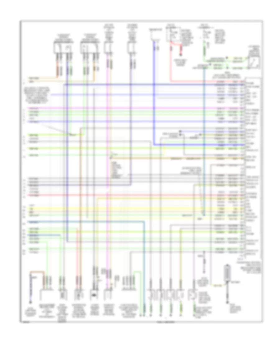
2.3L 2.3L, Engine Performance Wiring Diagram (2 of 4) for Ford Focus SVT 2004 List of elements for 2.3L, Engine Performance Wiring Diagram (2 of 4) for Ford Focus SVT 2004: 43 (engine control harn, near breakout for a/c compressor cycling switch) (engine control harn, near breakout for battery) s159 (engine control harn, near breakout for oil pressure switch) (engine control harn, near breakout to c211) s267 (fuel shutoff harn, near breakout to intake system) (left front (left front side of eng compt) s188 (on throttle body) throttle position sensor (tps) (top of engine) injection pressure sensor Air pump motor (left front corner of engine compt) Air pump relay Battery junction box (bjb) (left rear corner of engine compt) C270f Central junction box (cjb) (behind left side of dash) Exterior lights system Fuel pump Fuel pump driver module (under right rear seat) Fuel pump relay Fuel tank pressure transducer sensor (in fuel tank) Fuel tank unit Fuse 10a Fuse 15a Fuse 30a G103 (left side of engine compt) G301 (under right rear seat) Gearshift lever unit (a/t) Hot at all times Inertia fuel shutoff (ifs) switch (behind right kick panel) Manifold absolute pressure/ intake air temperature (map/iat) sensor (on intake system) O/d off switch Of engine compt) g100 Power steering pressure sensor (on power steering pump) Red S118 S121 S181 S191 S193 (junction box wiring harn, near battery junction box) S194 S197 S198 Secondary air injection bypass solenoid (right side of engine compt) Stoplamp switch (on brake pedal support) 2.3L, Engine Performance Wiring Diagram (3 of 4) for Ford Focus SVT 2004 List of elements for 2.3L, Engine Performance Wiring Diagram (3 of 4) for Ford Focus SVT 2004: 78 (a/t) (engine control harn, near breakout for a/c compressor cycling sw) (engine control harn, near breakout to a/c compressor cycling sw) (engine control harn, near breakout to pcm) (engine ctrl sensor ext harn, near breakout for ho2s 21) (engine ctrl sensor ext harn, near breakout for pnp sw) (engine ctrl sensor ext harn, near breakout to c1026) (in exhaust system) heated oxygen sensor (ho2s) 12 (in exhaust system) heated oxygen sensor (ho2s) 13 (m/t) (on clutch pedal support) (m/t) clutch pedal position switch (on left side of transmission) (a/t) transmission range (tr) sensor (top of transmission) (a/t) turbine shaft speed (tss) sensor 15s-ta17 15s-ta23 15s-ta24 15s-ta37 15s-ta38a 15s-ta40 15s-ta41 15s-ta42 15s-ta63 15s-ta64 15s-ta65 8-bb6 8-rj15 8-rj29 8-rj41 8-ta27 8-ta36 9-da1 9-rj29 91s-rj15 91s-rj41 91s-ta17 C175t C2220 Check engine indicator Computer data lines system Cpp sw Epc sol Exterior lights system G103 (left side of engine compt) G203 (right "a" pillar) Ho2s 21 ctrl Ho2s 21 sig Ho2s 22 ctrl Ho2s 22 sig Instrument cluster Nca Oss sens Output shaft speed (oss) sensor (a/t) (rear of transmission) Powertrain control module (pcm) (behind right side of dash, at base of "a" pillar) S161 S162 S163 S187 S189 S201 S212 S252 Shift sol Shift sol a Shift sol b Shift sol c Shift sol d Sig return Solid state Tft sens Tr sens, 1 Tr sens, 2 Tr sens, d Tr sens, p/n Tr sens, rev Transmission hardware unit (a/t) Tss sens Vehicle speed sensor (m/t) (rear of transmission) Vss sig 2.3L, Engine Performance Wiring Diagram (4 of 4) for Ford Focus SVT 2004 List of elements for 2.3L, Engine Performance Wiring Diagram (4 of 4) for Ford Focus SVT 2004: 90 (engine control harn, near breakout for a/c compressor cycling switch) (engine control sensor harn, near breakout for oil pressure switch) (left front of eng) (near breakout to intake system) (on intake system) idle air control (iac) valve (right side of engine compt) egr stepper motor 15-rl9a 15s-rr5 15s-rr6 15s-rr7 15s-rr8 31s-pa37 31s-rl10 31s-rl11 31s-rl12 31s-rl13 31s-rl20 31s-rl9 4-eb6 5-eb6 7-re8 8-8-rj14 8-rj11 8-rj16 8-rj18 8-rj20 8-rj28 8-rj3 8-rj33 8-rj4 9-re8 9-rj18 9-rj4 91s-pa51 91s-pa52 91s-pa53 91s-pa54 91s-rj14 C175e Camshaft position sensor (right rear of cyl head) Cht sens Ckp sens Cmp sig Coil 1 Coil 2 Coil 3 Coil 4 Coil on plug Crankshaft position sensor (lower left front of eng) Cylinder- head temperature sensor (on cylinder head) Egr coil 1 Egr coil 2 Egr coil 3 Egr coil 4 Fuel inj 1 Fuel inj 2 Fuel inj 3 Fuel inj 4 Fuel injectors G103 (left side of engine compt) G202 (right "a" pillar) Gen comm Gen monitor Generator Heated oxygen sensor (ho2s) 11 (in exhaust system) Ho2s 11 ctrl Ho2s 11 sig Iac valve Imrc mod Imrc sol 1 Imtv Inj press sig Inlet manifold runner control (imrc) solenoid 1 (on intake system) Intake manifold runner control (imrc) module (on left rear of engine) Intake manifold tuning valve (imtv) (on intake system) Knock sens Knock sensor Map sig Nca Powertrain control module (pcm) (behind right side of dash, at base of "a" pillar) Ref volt S156 S160 S169 S199 S252 S279 Sig return Tps sig Vbatt
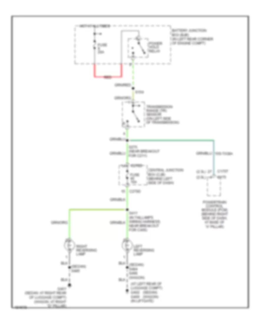
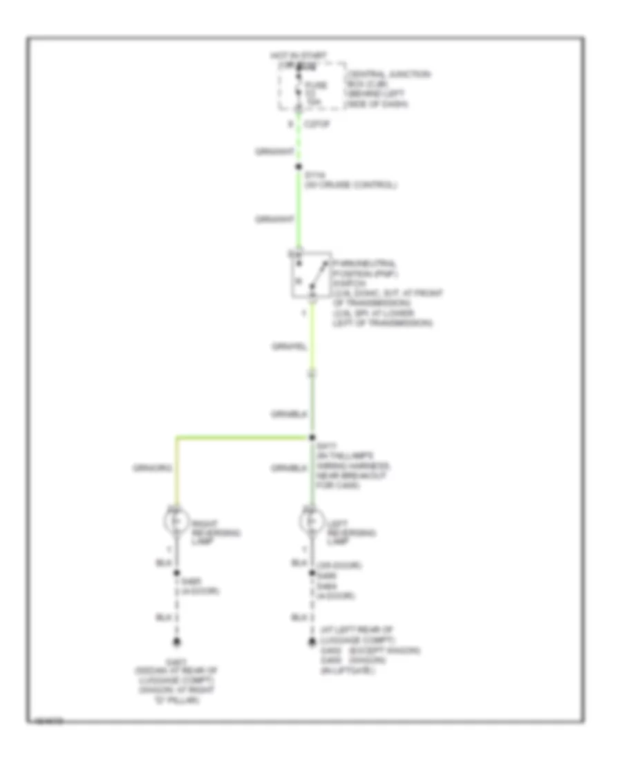
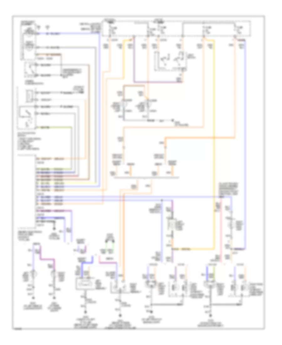
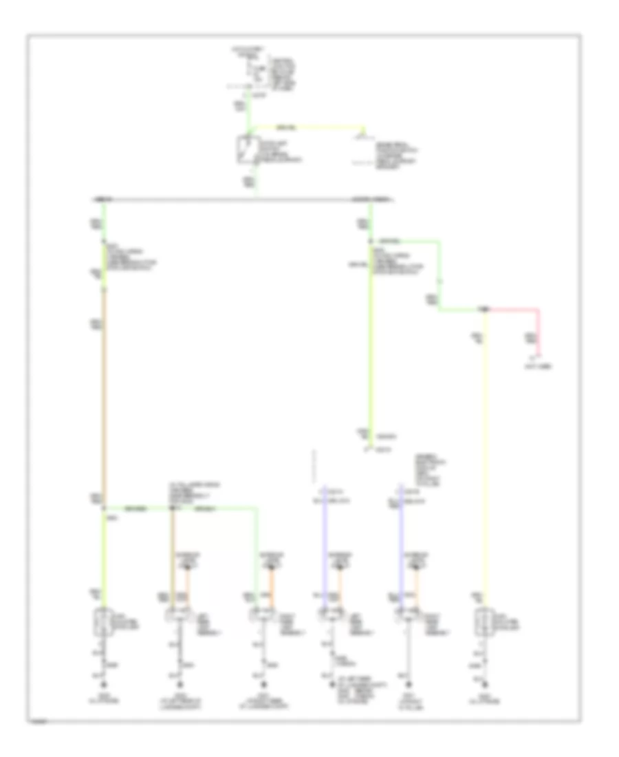
EXTERIOR LIGHTS Back-up Lamps Wiring Diagram, A/T for Ford Focus SVT 2004 List of elements for Back-up Lamps Wiring Diagram, A/T for Ford Focus SVT 2004: 22 (2.0l) (2.3l) (at left rear of luggage compt) g402 g400 (in liftgate) (sedan) (wagon) (sedan) s485 Battery junction box (bjb) (in left rear corner of engine compt) C175 C175t C270d Central junction box (cjb) (behind left side of dash) Fuse 10a Fuse 20a G401 (sedan: at right rear of luggage compt) (wagon: at right "d" pillar) Hot at all times Left reversing lamp Near breakout for c406) Power hold relay Powertrain control module (pcm) (behind right side of dash, at base of "a" pillar) Red Right reversing lamp S154 Transmission range (tr) sensor (on left side of transmission) Back-up Lamps Wiring Diagram, M/T for Ford Focus SVT 2004 List of elements for Back-up Lamps Wiring Diagram, M/T for Ford Focus SVT 2004: 13 (at left rear of luggage compt) g402 g400 (in liftgate) (except wagon) (wagon) C27of Central junction box (cjb) (behind left side of dash) Fuse 10a G401 (sedan: at rear of luggage compt) (wagon: at right "d" pillar) Hot in start or run Left reversing lamp Near breakout for c406) Park/neutral position (pnp) switch (2.0l dohc, svt: at front of transmission) (2.0l spi: at lower left of transmission) Right reversing lamp S114 (w/ cruise control) S485 (4-door) Park, Turn & Hazard Lamps Wiring Diagram for Ford Focus SVT 2004 List of elements for Park, Turn & Hazard Lamps Wiring Diagram for Ford Focus SVT 2004: 85 (at left rear of luggage compt) (at right ``a" pillar) g203 (in junction box wiring harness, near breakout for right front park/turn lamp) s132 (near breakout for instrument cluster) s212 1. right turn signal 2. flash right 3. neutral 4. flash left 5. left turn signal 2.0l 2.3l 29-dk20 29s-le18 29s-lg43 31-dk20 49s-lg12 49s-lg15 49s-lg19 49s-lg22 49s-lg4 49s-lg5 91-dk20 91s-lg1 91s-lg2 91s-lg8 C201a C201b C201c C201d C201e C220a C2220 C270d C270e C270f C452a C452b C462a C462b Central junction box (cjb) (behind left side of dash) Except sedan Fuse 10a Fuse 15a Fuse 7.5a G100 (at left front of engine compt) G102 (at right front of engine compartment) G300 (at right ``a" pillar) G400 (in tailgate) G401 (at rear of luggage compt) G401 (sedan: at rear of luggage compt) (wagon: at right "d" pillar) G402 G402 (wagon: on left "d" pillar) (sedan: at left rear of luggage compt) Generic electronic module (gem) (on right ``a" pillar) Hazard flasher switch Hot at all times Instrument cluster Left front park/ turn lamp Left front side lamp Left license plate lamp Left rear lamp assembly Left rear turn lamp Left side high intensity discharge headlamp Left turn ind Light switch Multi-function switch Nca Park Right front park/ turn lamp Right front side lamp Right license plate lamp Right rear lamp assembly Right rear turn lamp Right side high intensity discharge headlamp Right turn ind S104 (near breakout for g101) S109 S121 S130 S131 S484 S484 (4 door) S485 S485 (4 door) S496 Sedan Stop lamps circuit Turn W/ hid W/o hid Stop Lamps Wiring Diagram for Ford Focus SVT 2004 List of elements for Stop Lamps Wiring Diagram for Ford Focus SVT 2004: 31 (at left rear of luggage compt) g402 g400 (in liftgate) (at right "d" pillar) (in taillamps wiring harness, near breakout for g402) s412 (not used) (sedan) (wagon) 15s-aa72 3 door, wagon Brake pedal position switch (on brake pedal support bracket) C201a C201b C201d C270f Central junction box (cjb) (behind left side of dash) Exterior lamps circuit Fuse 15a G400 (in liftgate) G401 G401 (at right rear of luggage compt) G402 (at left rear of luggage compt) Generic electronic module (gem) (on right "a" pillar) High mounted stoplamp Hot in start or run Left rear lamp assembly Right rear lamp assembly S454 S484 S485 S496 S496 (wagon) Sedan Stoplamp switch (on brake pedal support)
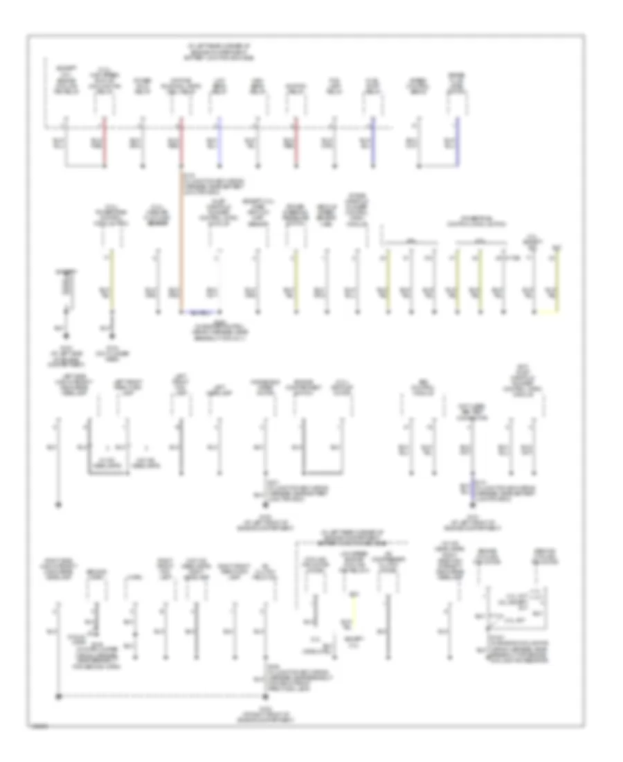
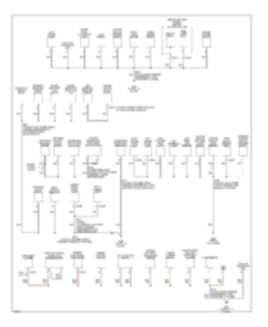
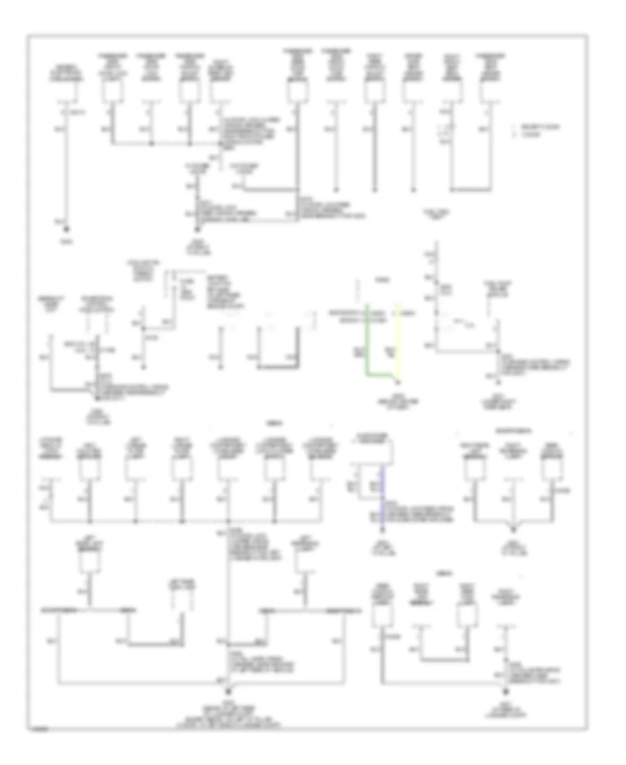
GROUND DISTRIBUTION Ground Distribution Wiring Diagram (1 of 3) for Ford Focus SVT 2004 List of elements for Ground Distribution Wiring Diagram (1 of 3) for Ford Focus SVT 2004: 68 (2.0l) powertrain control module (pcm) (2.3l) air pump motor (2.3l) high speed run-on cooling fan relay (2.3l) mass air flow (maf) sensor (except (except 2.3l) mass air flow (maf) sensor (in left rear corner of engine compartment) battery junction box (bjb) (not used) abs test connector (svt) inlet manifold runner control (imrc) module (w/ hid headlamps) right side high intensity discharge headlamp (w/o hid headlamps) right headlamp 2.0l 2.0l except svt 2.3l 2.3l) 2.3l, svt 87a A/c clutch field coil A/c compressor clutch diode Abs control module Battery Brake fluid level switch Breakout for engine cooling fan resistor) C175b Cooling fan motor diode Daytime running lamps (drl) relay Engine compartment switch Engine cooling fan motor Engine cooling fan relay Except 2.3l Fog lamp relay For right front park/turn lamp) Fuel pump relay G100 (at left front of engine compartment) G101 (at left front of engine compartment) G102 (at right front of engine compartment) G103 (at left side of engine compartment) G104 (on cylinder head) High beam relay Horn Ignition relay Inlet manifold runner control (imrc) module Intake manifold runner control (imrc) module Junction box) Left front fog lamp Left front park/turn lamp Left headlamp Left side high intensity discharge headlamp Low beam relay Low speed engine cooling fan relay a Power hold relay Power steering pressure switch Powertrain control module (pcm) Right front fog lamp Right front park/turn lamp Right side high intensity discharge headlamp S118 (in junction box wiring harness, near battery junction box) S149 (in horn jumper wiring harness, near breakout for second horn) S252 (in engine control wiring harness, near breakout for c211) Second cooling fan motor Second horn Speed control servo Svt Vehicle speed sensor (vss) W/ dual horn W/ hid headlamps W/o hid headlamps Windshield wiper motor Ground Distribution Wiring Diagram (2 of 3) for Ford Focus SVT 2004 List of elements for Ground Distribution Wiring Diagram (2 of 3) for Ford Focus SVT 2004: 72 (2.0l) (2.3l) (3 door) driver side front seat adjust switch (3-door model) auxiliary instrument cluster (behind left side of dash) central junction box (cjb) (not used) (svt) power point (w/ front & rear power windows) (w/ front power windows) (wagon) cargo space lamp 3 door Assembly, under driver's seat) C201d C220a C270c C270h C402b C452a C462a C489b C504a C918b Clock spring Data link connector (dlc) Decklid relay Driver side door lock switch Driver side front door ajar switch Driver side front door lock unit Driver side rear door ajar switch Except 3 door Exterior liftgate/ decklid release switch Exterior rear view mirror switch Front cigar lighter Front interior lamp G200 (at left ``a" pillar) G203 (at right ``a" pillar) G204 (at left ``a" pillar) G400 (wagon) (in liftgate) Generic electronic module (gem) Hazard flasher switch Heater blower switch Heater control module Heater panel illumination lamp High mounted stop lamp Instrument cluster Left exterior rear view mirror Left front seat back heater Left license plate lamp Left rear lamp assembly Left rear window adjust switch Left reversing lamp Liftgate/ decklid anti-theft inhibit switch Liftgate/ decklid latch assembly Liftgate/ decklid release switch Light switch Master window adjust switch Moonroof adjust switch Multi-function switch Nca Near breakout for instrument cluster) One-touch window relay Passive anti-theft transceiver module Rear window defrost grid Rear wiper relay Right license plate lamp Roof opening panel unit S270 (in door lock feed wiring harness, at breakout for g200) S377 (in door lock feed wiring harness, near breakout for left front door ajar switch) S496 (in door lock jumper wiring harness, near breakout for g400) S597 (in door lock jumper wiring harness, near breakout for master window adjust switch) Traction control system (tcs) disable switch Wiper/ washer switch Wiring harness, near breakout for cargo space lamp) Ground Distribution Wiring Diagram (3 of 3) for Ford Focus SVT 2004 List of elements for Ground Distribution Wiring Diagram (3 of 3) for Ford Focus SVT 2004: 70 (2.3l) (bosch) (exc 2.3l) (exc bosch) c290c (in door lock jumper wiring harness, near breakout for right front power window motor) s694 2.3l 3 door At right ``a" pillar) Battery junction box (bjb) (in left rear corner of engine compt) C175b C201a C2188a C290c C402b Cooling fan run-on thermo switch Driver side seat heater switch Except 3 door Except sedan Fuel pump driver module Fuel tank unit Fuse test point G201 (at left ``a" pillar) G202 (at right ``a" pillar) G205 (behind center of dash) G300 (at right ``a" pillar) G301 (under right rear seat) G302 G401 (at rear of luggage compt) G401 (at right ``d" pillar) G402 (sedan: at left rear of luggage compt) (except sedan : on left "d" pillar) (3 door : at left side of luggage compt) Gearshift lever unit Generic electronic module (gem) High mounted stoplamp Left license plate lamp Left rear lamp assembly Left rear turn lamp Left reversing lamp Liftgate/ decklid latch assembly Luggage compartment lid release relay Luggage compartment lid release solenoid Luggage compartment lock cylinder switch Nca Passenger side door lock switch Passenger side front door ajar switch Passenger side front door lock unit Passenger side rear door ajar switch Passenger side seat heater switch Passenger side window adjust switch Powertrain control module (pcm) Radio Rear window defrost Rear window defrost grid Right exterior rear view mirror Right front seat back heater Right license plate lamp Right rear lamp assembly Right rear turn lamp Right rear window adjust switch Right reversing lamp S105 S378 (in door lock feed wiring harness, near breakout for c800) S381 (in engine control wiring harness, near breakout for g301) S403 (in door lock feed wiring harness, near breakout for subwoofer amplifier) S448 (2.3l) S484 (in tail lamps wiring harness, near grommet at left rear of vehicle) S485 (in taillamps wiring harness, near breakout for g401) Sedan Subwoofer amplifier W/ power locks W/o power locks
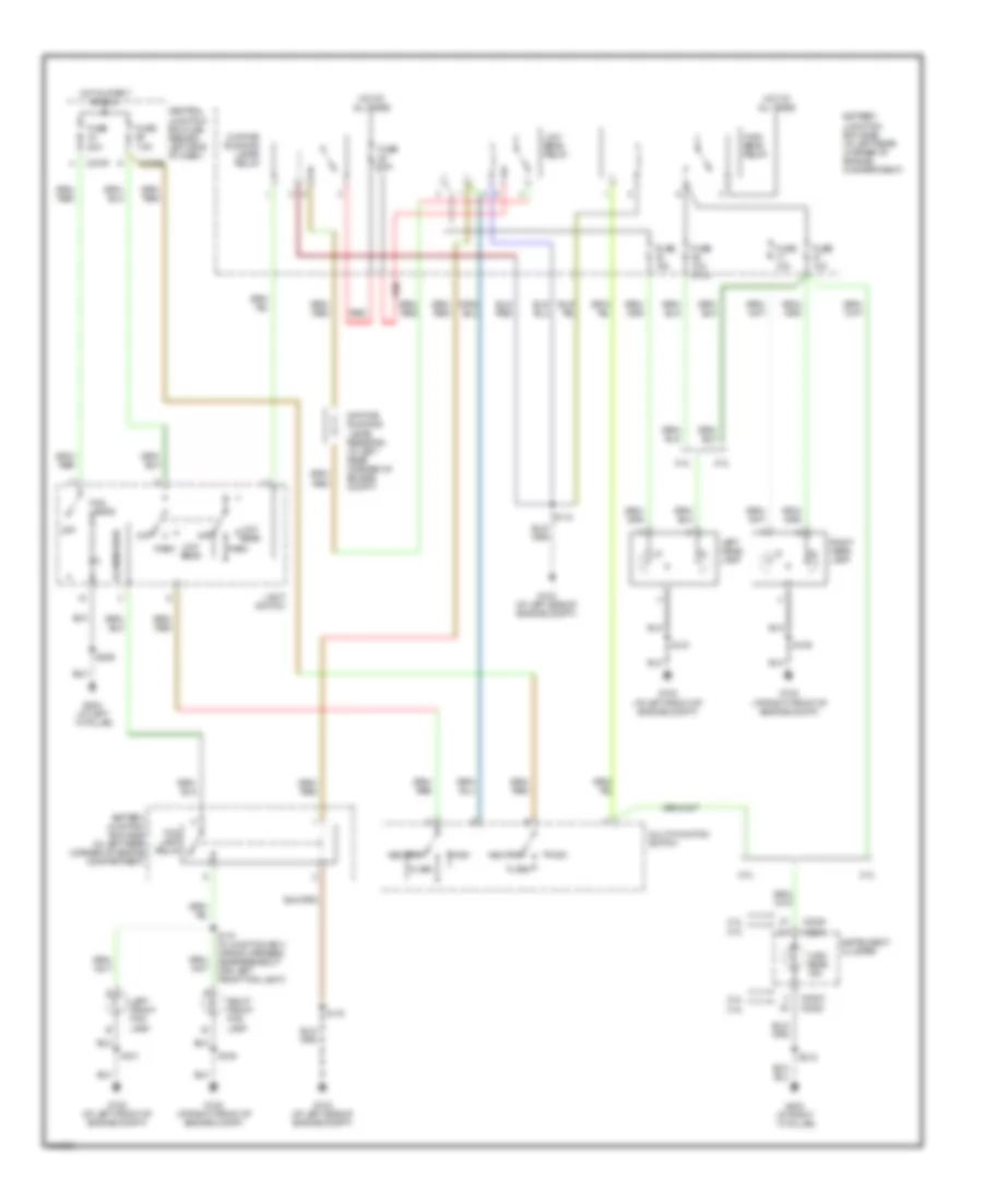
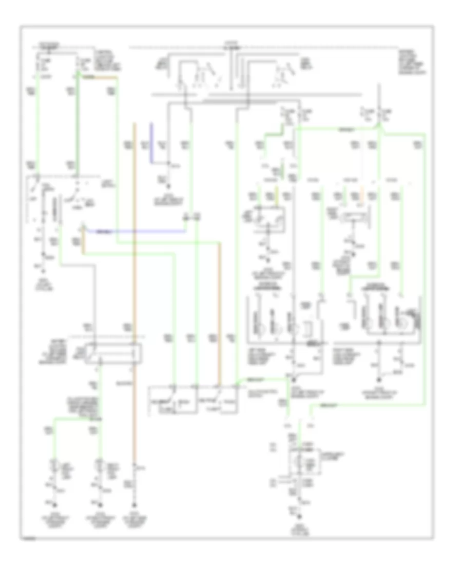
HEADLIGHTS Headlights Wiring Diagram, with DRL for Ford Focus SVT 2004 List of elements for Headlights Wiring Diagram, with DRL for Ford Focus SVT 2004: 47 2.0l 2.3l Battery junction box (bjb) (in left rear corner of engine compartment) C220a C2220 C270e C270f Central junction box (cjb) (behind left side of dash) Daytime running lamps relay Daytime running lamps resistor (in left rear corner of engine compt) Flash Fog lamp relay Fog lamps Fuse 10a Fuse 10a (2.3l) Fuse 20a Fuse 7.5a G100 (at left front of engine compt) G102 (at right front of engine compt) G103 (at left side of engine compt) G203 (at right ``a" pillar) G204 (at left ``a" pillar) High High beam ind High beam relay Hot at all times Hot in start or run Illumination Instrument cluster Left front fog lamp Left head- lamp Light switch Low beam Low beam relay Multi-functon switch Neutral Off Park Red Right front fog lamp Right head- lamp S109 S110 (in junction box wiring harness, near breakout for left front fog light) S118 S121 S206 S212 Headlights Wiring Diagram, without DRL for Ford Focus SVT 2004 List of elements for Headlights Wiring Diagram, without DRL for Ford Focus SVT 2004: 56 (in junction box wiring harness, near breakout for left front fog light) s110 2.0l 2.3l All times Battery junction box (bjb) (in left rear corner of engine compt) C220a C2220 C2220 c220a C270e C270f Central junction box (cjb) (behind left side of dash) Exterior lights system Flash Fog lamp relay Fog lamps Fuse 10a Fuse 10a (2.3l) Fuse 20a Fuse 7.5a G100 (at left front of engine compt) G102 (at right front of engine compt) G103 (at left side of engine compt) G203 (at right ``a" pillar) G204 (at left ``a" pillar) Head lamp High High beam High beam ind High beam relay Hot at Hot in run or start Illumination Instrument cluster Left front fog lamp Left head- lamp Left side high intensity discharge headlamp Light shield Light switch Low beam Low beam relay Multi-functon switch Neutral Off Park Parking lamp Right front fog lamp Right head- lamp Right side high intensity discharge headlamp S109 S118 S121 S206 S212 Turn signal W/ hid W/o hid
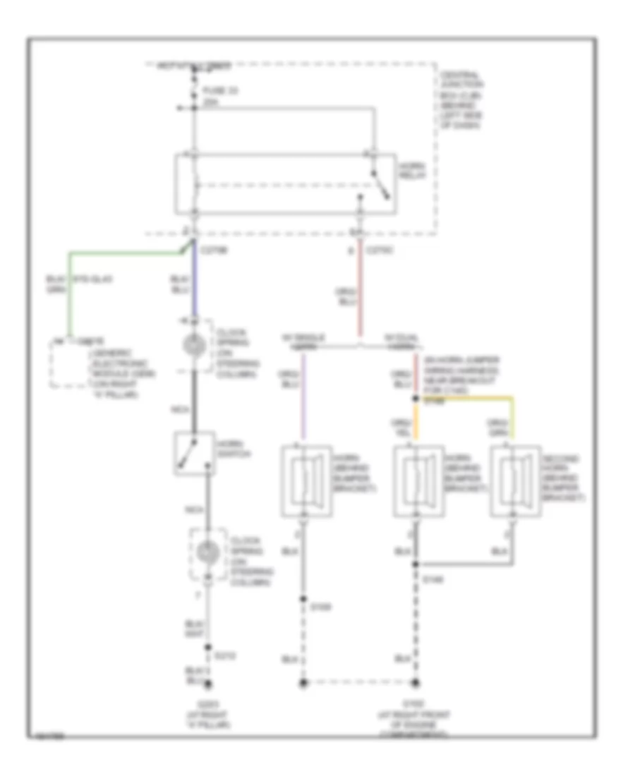
HORN Horn Wiring Diagram for Ford Focus SVT 2004 List of elements for Horn Wiring Diagram for Ford Focus SVT 2004: 24 (at right front of engine compartment) (in horn jumper wiring harness, near breakout for c140) s148 20a Box (cjb) (behind left side of dash) C201e C270b C270c Central junction Clock spring (on steering column) Fuse 33 G102 G203 (at right "a" pillar) Generic electronic module (gem) (on right "a" pillar) Horn (behind bumper bracket) Horn relay Horn switch Hot at all times Nca S109 S149 S212 Second horn (behind bumper bracket) W/ dual horn W/ single horn
INSTRUMENT CLUSTER
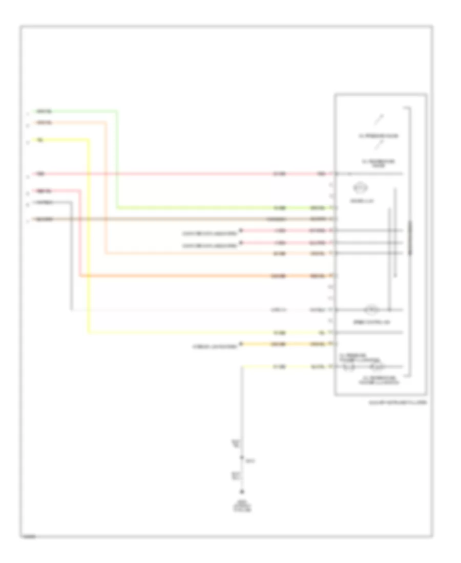
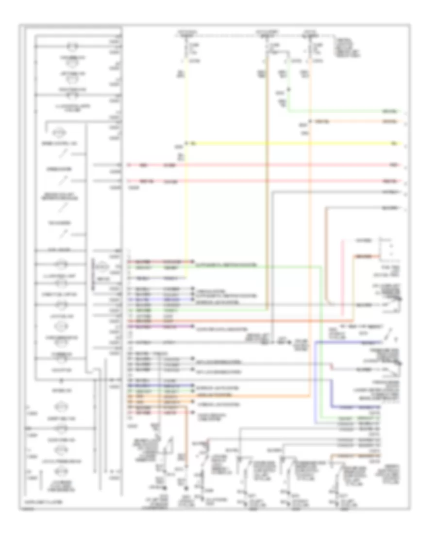
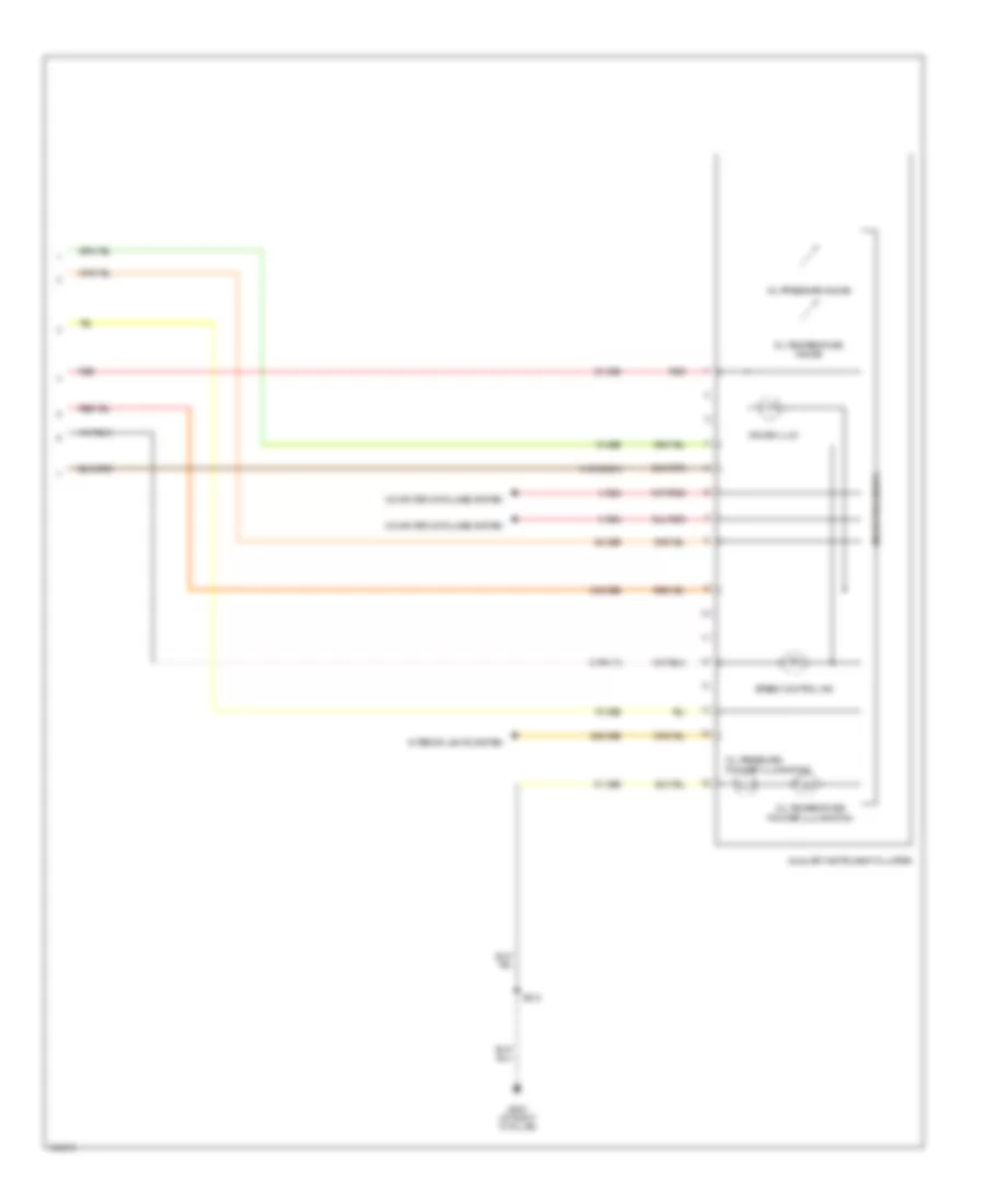
2.0L 2.0L, Instrument Cluster Wiring Diagram, with Auxiliary Instrument Cluster (2 of 2) for Ford Focus SVT 2004 List of elements for 2.0L, Instrument Cluster Wiring Diagram, with Auxiliary Instrument Cluster (2 of 2) for Ford Focus SVT 2004: 25 15-ge6 29-ge6 29s-ge6 30-ge6 30s-ge6 31s-gc20a 4-eg2 5-eg2 75-ge6 8-pg11a 91-ge6 Auxiliary instrument cluster Computer data lines system G203 (at right "a" pillar) Gauge illum Interior lights system Microprocessor Oil pressure Oil pressure gauge Oil temperature Oil temperature gauge Pointer illumination Red S212 Speed control ind
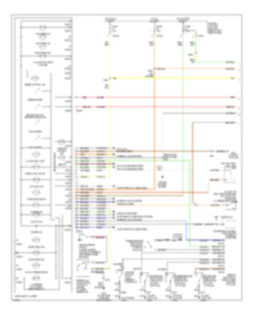
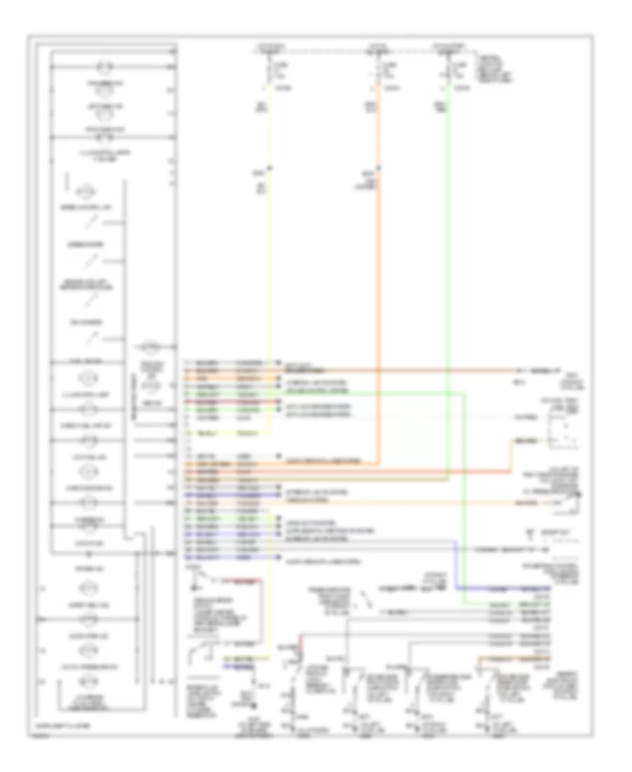
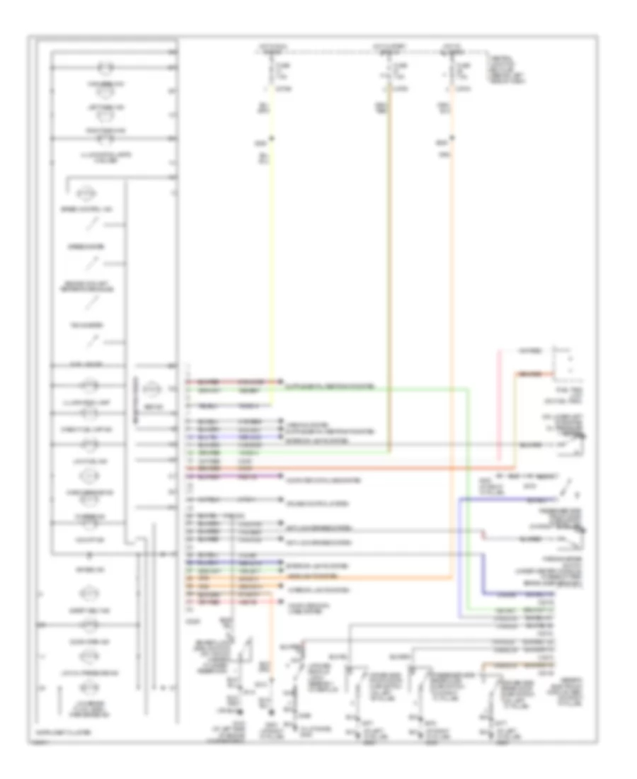
2.3L 2.3L, Instrument Cluster Wiring Diagram, with Auxiliary Instrument Cluster (2 of 2) for Ford Focus SVT 2004 List of elements for 2.3L, Instrument Cluster Wiring Diagram, with Auxiliary Instrument Cluster (2 of 2) for Ford Focus SVT 2004: 25 15-ge6 29-ge6 29s-ge6 30-ge6 30s-ge6 31s-gc20a 4-eg2 5-eg2 75-ge6 8-pg11a 91-ge6 Auxiliary instrument cluster Computer data lines system G203 (at right "a" pillar) Gauge illum Interior lights system Microprocessor Oil pressure Oil pressure gauge Oil temperature Oil temperature gauge Pointer illumination Red S212 Speed control ind 2.3L, Instrument Cluster Wiring Diagram, without Auxiliary Instrument Cluster for Ford Focus SVT 2004 List of elements for 2.3L, Instrument Cluster Wiring Diagram, without Auxiliary Instrument Cluster for Ford Focus SVT 2004: 96 (at left "a" pillar) g200 (at right "a" pillar) g300 (in liftgate) g400 (on lower left of engine) oil pressure switch 15-gg14 15s-aa17 15s-aa17 15s-aa17 15s-le11 29-gg14 29s-gg14 31s-aa7 31s-cf28 31s-cf45 31s-gc20 31s-gc6 31s-ge44 31s-ge49 31s-gl12 31s-gl16 31s-gl19 31s-gl20 31s-gl9 4-ec7b 49s-lg15 49s-lg22 5-ec7b 75-gg14 8-ga7 8-pg11 9-ga7 91-gg14 91s-ja13b 91s-ja14 Abs ind Air bag ind Anti-lock brakes system Brake fluid level switch (on top of master cylinder reservoir) C201a C201b C201d C201e C2220 C270a C270b C270d Central junction box (cjb) (behind left side of dash) Charge ind Check engine ind Check fuel cap ind Computer data lines system Cruise control system Door open ind Driver side front door ajar switch (on left "b" pillar) Driver side rear door ajar switch (on left "c" pillar) Engine coolant temperature gauge Exterior lights system Fuel gauge Fuel tank unit (on fuel tank) Fuse 7.5a G103 (at left side of engine compartment) G203 (at right "a" pillar) G300 (at right "a" pillar) Generic electronic module (gem) (on right "a" pillar) Headlights system High beam ind Hot at all times Hot in run or acc Hot in start or run Illumination lamp Illumination lamps (3 bulbs) Instrument cluster Interior lights system Left turn ind Liftgate/ decklid latch assembly (in decklid) Low brake fluid level/ park brake ind Low fuel ind Low oil pressure ind Microprocessor Nca O/d off ind Parking brake switch (under center console, at base of park brake lever bracket) Passenger side front door ajar switch (on right "b" pillar) Passenger side rear door ajar switch (on right "c" pillar) Right turn ind S118 S212 S249 S250 S377 S378 S496 Safety belt ind Speed control ind Speedometer Tachometer Warning system
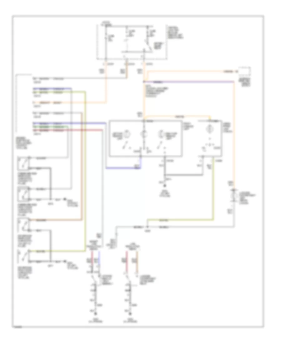
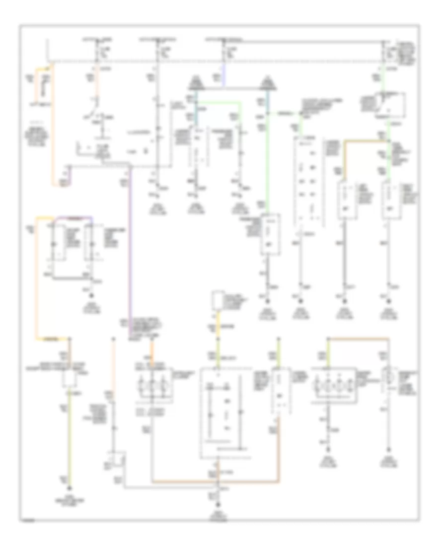
INTERIOR LIGHTS Courtesy Lamps Wiring Diagram for Ford Focus SVT 2004 List of elements for Courtesy Lamps Wiring Diagram for Ford Focus SVT 2004: 52 29-aa17 31s-gl12 31s-gl16 31s-gl19 31s-gl20 31s-gl9 31s-lc22 31s-lc7 Battery saver relay C201a C201b C201c C201d C201e C270a C270c C270f C489a C489b C918a C918b Cargo space lamp (wagon) Central junction box(cjb) (behind left side of dash) Door Driver side front door ajar switch (on left "b" pillar) Driver side rear door ajar switch (on left "c" pillar) Except late production sedan Exterior rear view mirror switch Front interior lamp Fuse 20a Fuse 7.5a G200 (at left "a" pillar) G300 (at right "a" pillar) G400 (in liftgate) Generic electronic module (gem) (on right "a" pillar) Hot at all times Late production sedan Left map reading lamp Liftgate/ decklid latch assembly Luggage compartment lamp (sedan, 3-door) Luggage compartment lid release relay Nca Nca nca Passenger side front door ajar switch (on right "b" pillar) Passenger side rear door ajar switch (on right "c" pillar) Right map reading lamp S273 (in door lock feed wiring harness, at breakout for c210) S377 S378 S469 S496 S914 Instrument Illumination Wiring Diagram for Ford Focus SVT 2004 List of elements for Instrument Illumination Wiring Diagram for Ford Focus SVT 2004: 62 (2.0l) (2.3l) (2.3l) (2.0l) (bosch radio) (in door lock jumper wiring harness, near breakout for c510) (in main wiring harness (14401), near breakout for front cigar lighter) s204 29s-le18 Auxiliary instrument cluster (3-door) C201d C2188a c290c (except bosch radio) C220a c2220 C2220 c220a C270d C270e C290c C504a C504b Central junction box (cjb) (behind left side of dash) Driver side seat heater switch Fuse 10a Fuse 25a Fuse 7.5a G200 (at left "a" pillar) G202 (at right "a" pillar) G203 (at right "a" pillar) G204 (at left "a" pillar) G205 (behind center of dash) G300 (at right "a" pillar) Gearshift lever unit (under center console) Generic electronic module (gem) (on right "a" pillar) Hazard flasher switch Head Heater control module (behind dash) Heater panel illumination lamp Hot at all times Hot in start or run Illumination Instrument cluster Left rear window adjust switch Light switch Lock Master window adjust switch Off Park Passenger side seat heater switch Passenger side window adjust switch Pulse width module Radio Right rear window adjust switch S206 S212 S356 S358 (near breakout for driver's seat) S377 S378 S501 S597 S694 Traction control system (tcs) disable switch W/ a/c W/ rear power windows W/o a/c W/o rear power windows
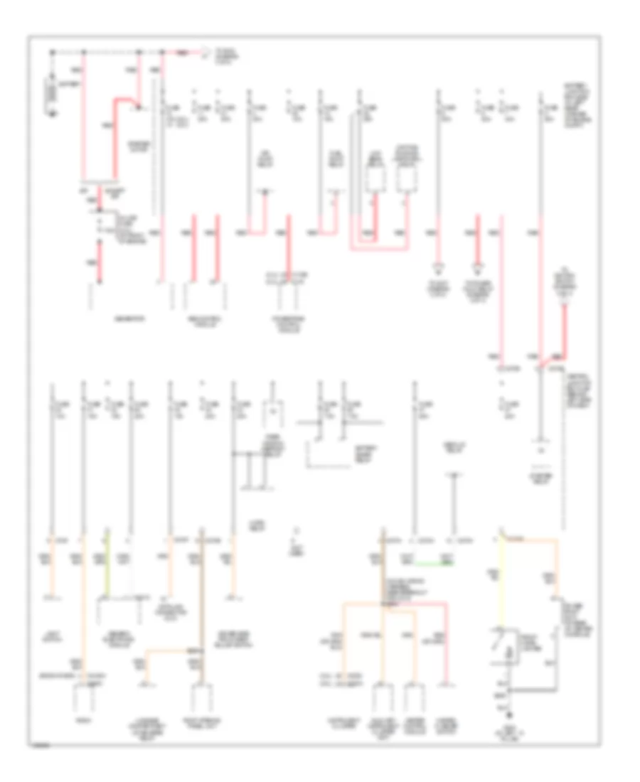
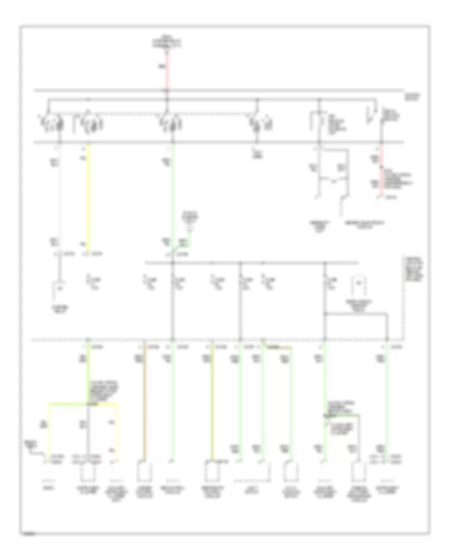
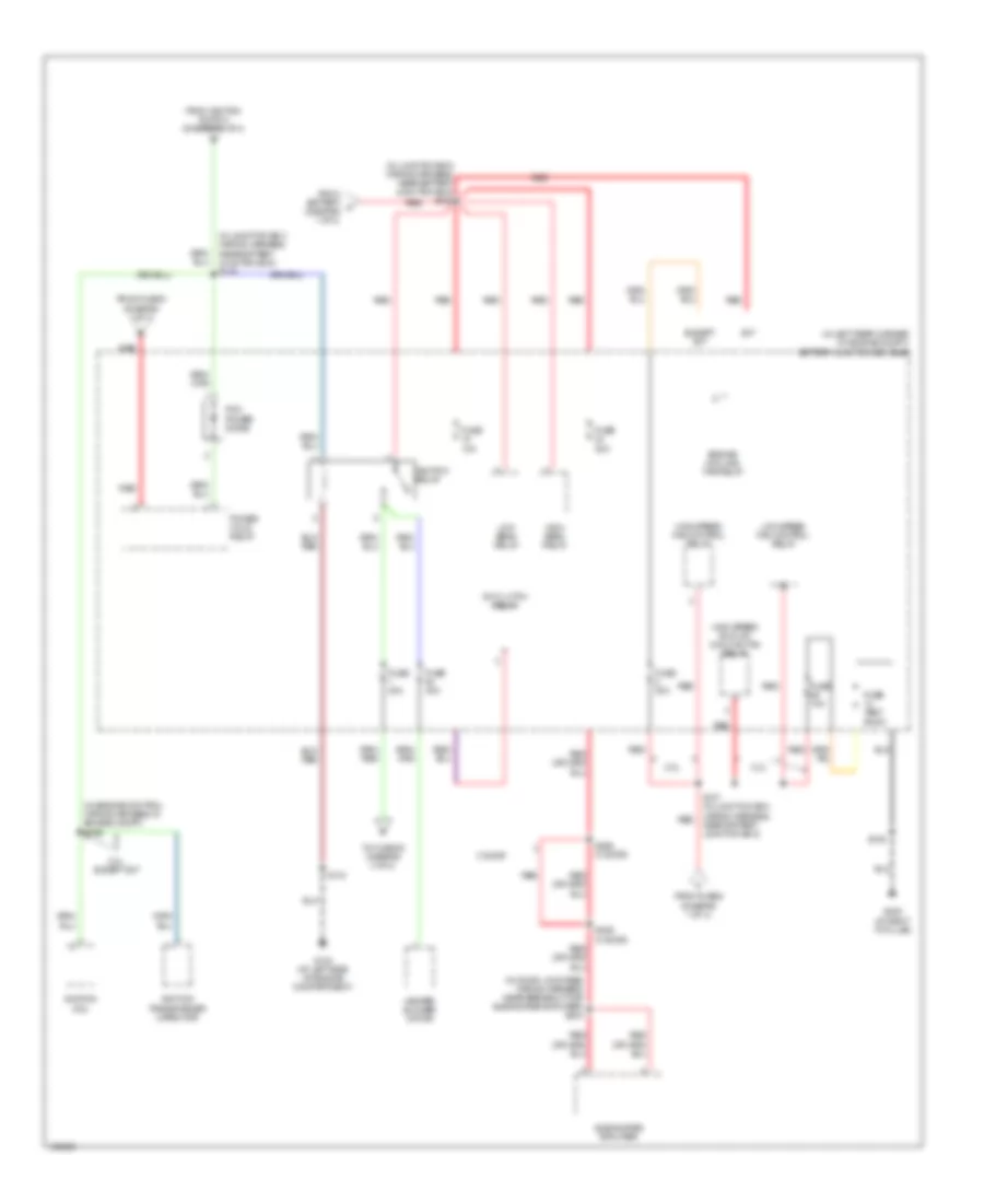
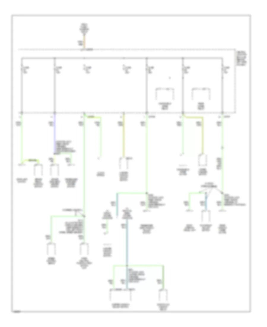
POWER DISTRIBUTION Power Distribution Wiring Diagram (1 of 4) for Ford Focus SVT 2004 List of elements for Power Distribution Wiring Diagram (1 of 4) for Ford Focus SVT 2004: 70 (2.0l) (2.0l) (2.3l) (2.3l) (bosch radio) (in main wiring harness, near breakout for c213) s249 (not used) 175a 270d Abs control module Air pump relay Auxiliary instrument cluster (svt) Battery Battery junction box (bjb) (in left rear corner of engine compt) Battery saver relay C175 C175b C201c C2188a C220a C2220 C270a C270b C270e C270f C270g C270h C290c Central junction box (cjb) (behind left side of dash) Data link connector (dlc) Daytime running lamps (drl) relay Decklid relay Driver side front seat adjust switch Except spi Front cigar lighter Fuel pump relay Fuse 10a Fuse 10a 1a Fuse 15a Fuse 20a Fuse 25a Fuse 30a Fuse 40a Fuse 50a Fuse 7.5a G204 (at left ``a" pillar) Generator Generic electronic module Hazard flasher switch Heater control module Horn relay In-line fuse (2.3l) (at front of engine) Instrument cluster Light switch Low beam relay Luggage compartment lid release relay Power point (svt) (at rear of center console) Powertrain control module Radio Rear window defrost relay Red Roof opening panel unit S206 S259 Spi Starter motor Starter relay To ignition switch (diagram 2 of 4) To power hold relay (diagram 3 of 4) To s102 (diagram 3 of 4) To s107 (diagram 3 of 4) Power Distribution Wiring Diagram (2 of 4) for Ford Focus SVT 2004 List of elements for Power Distribution Wiring Diagram (2 of 4) for Ford Focus SVT 2004: 50 (2.0l) (2.3l) (in main wiring harness, behind dash) s248 (in main wiring harness, near breakout for instrument cluster) s250 (not used) A/t Abs control module Acc Auxiliary instrument cluster Auxiliary instrument cluster (svt) Bosch radio C201d C2041b C2188a C220a C2220 C270b C270c C270d C270e C270f C290c Central junction box (cjb) (behind left side of dash) From starter relay (diagram 1 of 4) Fuse 20a Fuse 7.5a Gearshift lever unit Generic electronic module Heater control module Ignition switch Instrument cluster Key in ignition switch Key removal inhibit solenoid (a/t) Light switch Lock Lock off Multi- function switch Off Passive anti-theft transceiver module Radio Rear window defrost relay Red Restraints control module Run Run off S215 (in main wiring harness, near breakout for g203) Start Starter relay To s119 (diagram 3 of 4) W/ auxiliary instrument cluster Power Distribution Wiring Diagram (3 of 4) for Ford Focus SVT 2004 List of elements for Power Distribution Wiring Diagram (3 of 4) for Ford Focus SVT 2004: 42 (in door lock feed wiring harness, near breakout for subwoofer amplifier) s404 (in engine control wiring harness, in engine compt) s195 (in junction box wiring harness, near battery junction box) s102 (in junction box wiring harness, near battery junction box) s119 (in left rear corner of engine compt) battery junction box (bjb) 2.0l 2.0l except svt 2.3l 3 door A/c clutch relay Engine cooling fan relay Except svt From battery a (diagram 1 of 4) From fuse 6 (diagram 1 of 4) From fuse 9 (diagram 1 of 4) From ignition switch (diagram 2 of 4) Fuse 10a Fuse 30a Fuse 40a Fuse test point G103 (at left side of engine compartment) G202 (at right "a" pillar) Heater blower motor High beam relay High speed fan control relay High speed run-on cooling fan relay Ignition coil Ignition relay Ignition transformer capacitor Low beam relay Low speed fan control relay Pcm power diode Power hold relay Red S105 S107 (in junction box wiring harness, near battery junction box) S118 S292 (3 door) S406 (3 door) Subwoofer amplifier Svt To fuse 53 (diagram 4 of 4) Power Distribution Wiring Diagram (4 of 4) for Ford Focus SVT 2004 List of elements for Power Distribution Wiring Diagram (4 of 4) for Ford Focus SVT 2004: 37 (in door lock feed wiring harness, near breakout for driver's seat) s357 Brake pedal position switch C270e C270f C270g C504a C504b Central junction box (cjb) (behind left side of dash) Clock spring Driver side seat heater switch From fuse 1 (diagram 3 of 4) Fuse 10a Fuse 15a Fuse 20a Fuse 25a Master window adjust switch Moonroof adjust switch One-touch window relay Park/ neutral position (pnp) switch (m/t) Passenger side seat heater switch Passenger side window adjust switch Rear window wiper motor Rear wiper relay Roof opening panel unit S114 (in junction box wiring harness, near breakout for left front wheel speed sensor) S253 (in door lock feed wiring harness, at breakout for g200) S356 (in door lock feed wiring harness, near breakout for c210) S501 (in door lock jumper wiring harness, near breakout for c510) Speed control servo Stoplamp switch W/ front & rear power windows W/ front power windows W/ roof opening panel W/ speed control Windshield wiper motor Windshield wiper relay Wiper/ washer switch
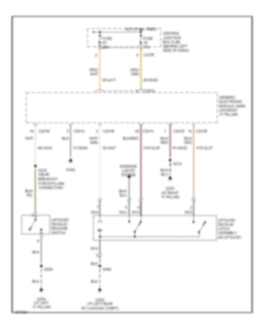
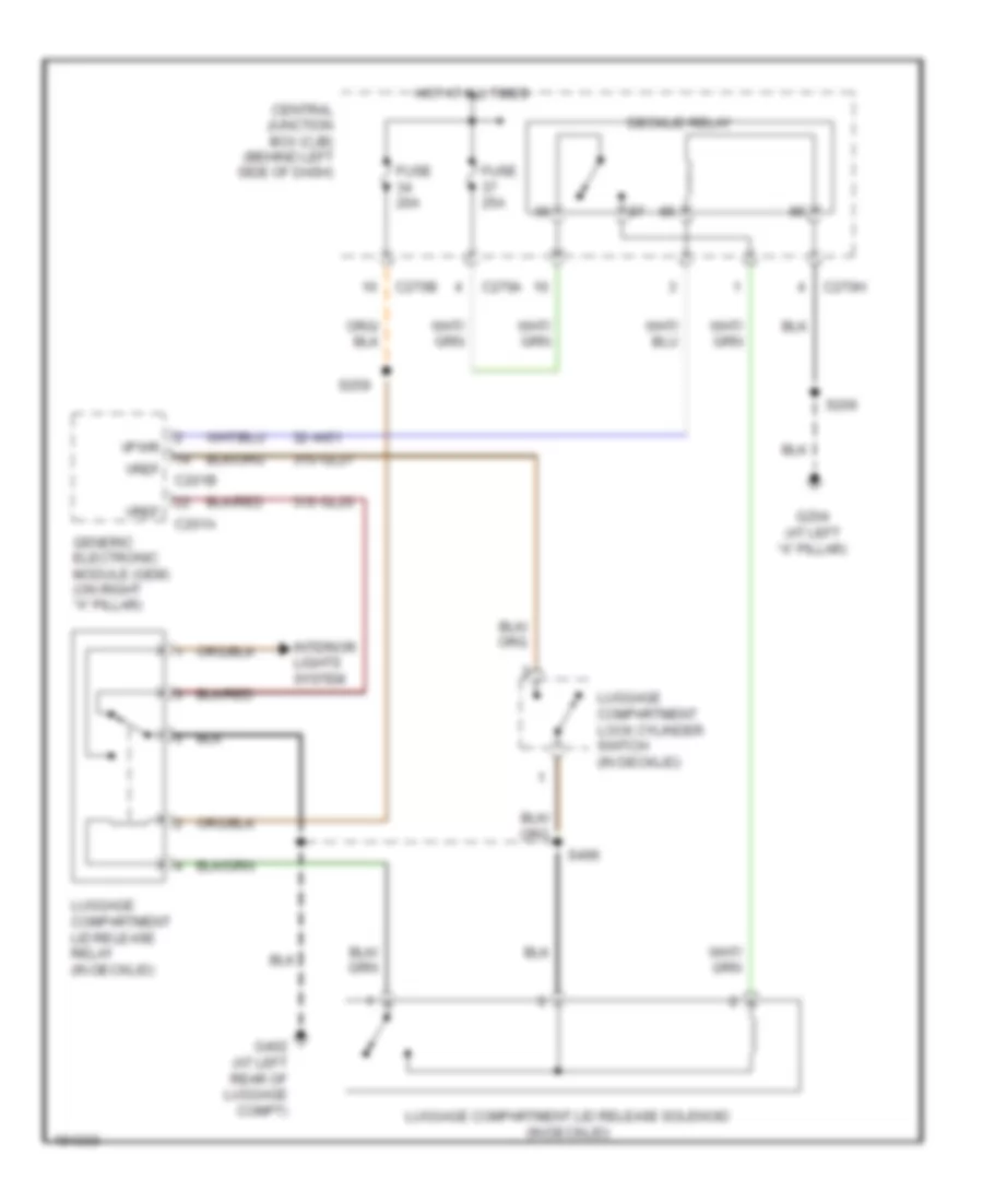
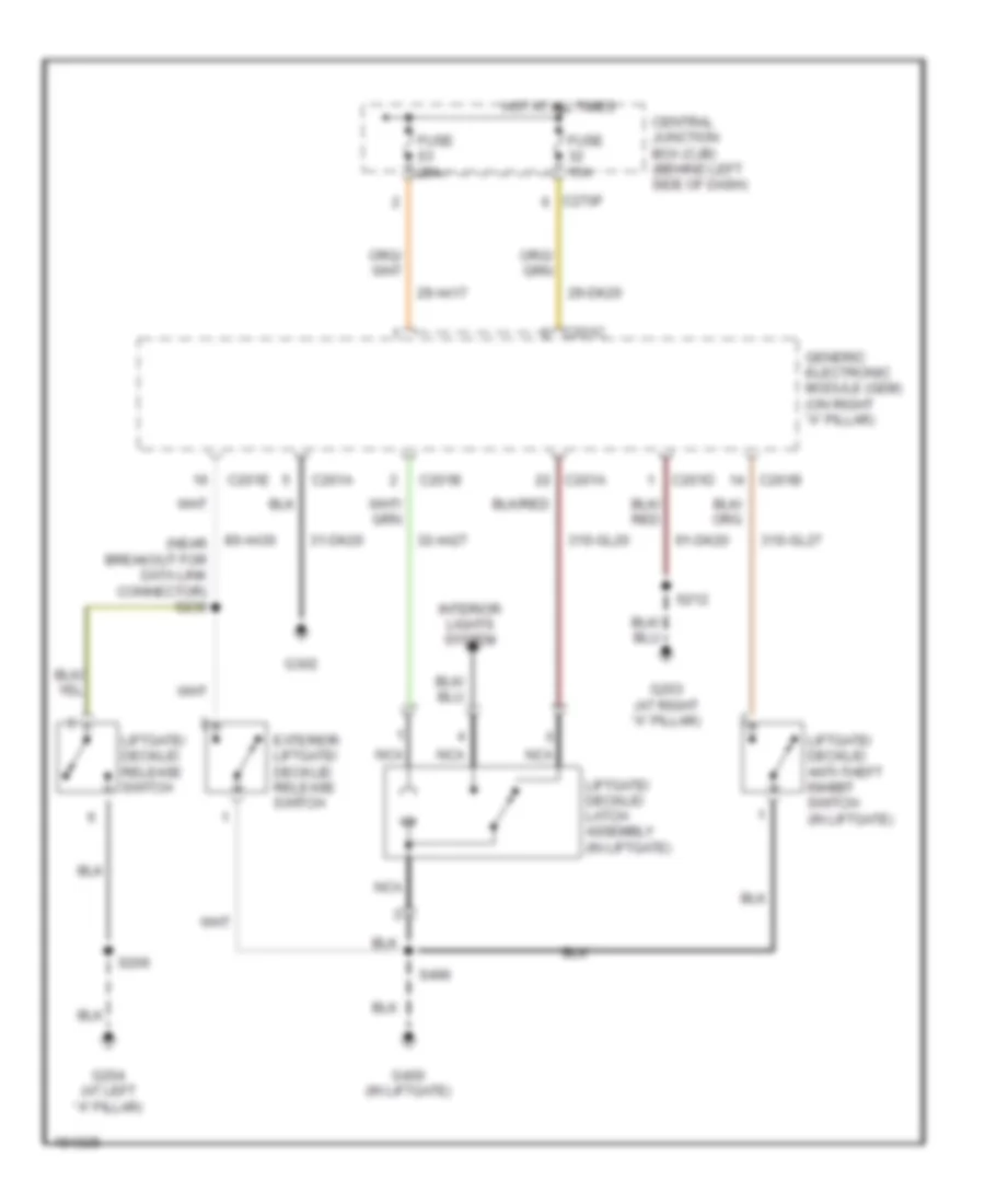
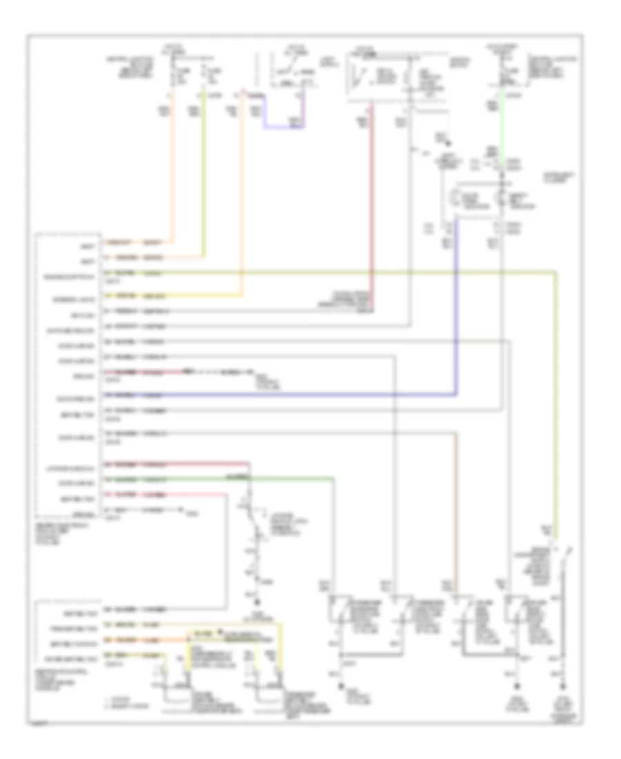
POWER DOOR LOCKS Power Door Locks Wiring Diagram (1 of 2) for Ford Focus SVT 2004 List of elements for Power Door Locks Wiring Diagram (1 of 2) for Ford Focus SVT 2004: 82 (behind dash panel) antenna (near breakout for generic electronic module) (not used) 15s-aa17 15s-aa72 2.0l 2.3l 29-aa17 29-dk20 31-dk20 31s-aa39 31s-aa61 31s-aa62 31s-aa63 31s-aa64 31s-aa7 31s-aa85 31s-gl12 31s-gl16 31s-gl19 31s-gl20 31s-gl27 31s-gl7 31s-gl9 31s-lc7 32-aa27 32-aa59a 32-aa59b 32-aa59c 32-aa59d 33-aa59 8-ee9 8s-aa30 91-aa17 91-dk20 91s-gl43 91s-lg8 C201a C201b C201c C201d C201e C220a C2220 C270f Central junction box (cjb) (behind left side of dash) Data link connector (dlc) (under left side of dash, on central junction box) Driver side door lock switch Engine compartment switch (in front center of engine compt) Exterior liftgate/ decklid release switch Exterior lights system Fuse 15a Fuse 20a G100 (at left front of engine compt) G200 (at left "a" pillar) G203 (at right "a" pillar) G204 (at left "a" pillar) G300 (at right "a" pillar) G400 (in liftgate) Generic electronic module (gem) (on right "a" pillar) Horns system Hot at all times Illumination Instrument cluster Interior lights system Liftgate/ decklid release switch Lock Passenger side door lock switch S121 S202 S206 S210 S212 S230 (in main wiring harness, near breakout for data link connector) S375 S376 S496 S597 S694 Stoplamp switch (on brake pedal support) Unlock Wagon Power Door Locks Wiring Diagram (2 of 2) for Ford Focus SVT 2004 List of elements for Power Door Locks Wiring Diagram (2 of 2) for Ford Focus SVT 2004: 50 (at left "a" pillar) g200 (at right "a" pillar) g300 (in decklid) liftgate/decklid latch assembly (in decklid) luggage compartment lid release relay (in decklid) luggage compartment lock cylinder switch (in liftgate) liftgate/decklid anti-theft inhibit switch (in liftgate) liftgate/decklid latch assembly (not used) (sedan: at left rear of luggage compt) (3-door: at left side of luggage compt) C270a C270b C270h Central Central junction box (cjb) (behind left side of dash) Central lock Decklid relay Driver side front door ajar switch (on left "b" pillar) Driver side front door lock unit (in driver door) Driver side rear door ajar switch (on left "c" pillar) Fuse 20a Fuse 25a G200 (at left "a" pillar) G204 (at left "a" pillar) G300 (at right "a" pillar) G400 (in liftgate) G402 Hot at all times Interior lights system Left rear door lock unit (in left rear door) Lock Luggage compartment lid release solenoid (in decklid) Nca Passenger side front door ajar switch (on right "b" pillar) Passenger side front door lock unit (in passenger door) Passenger side rear door ajar switch (on right "c" pillar) Reset Right rear door lock unit (in right rear door) S206 S259 S360 (in door lock feed wiring harness, near breakout for passenger's seat) S377 S378 S496 S597 S694 Sedan early production Sedan late production Set Unlock Wagon
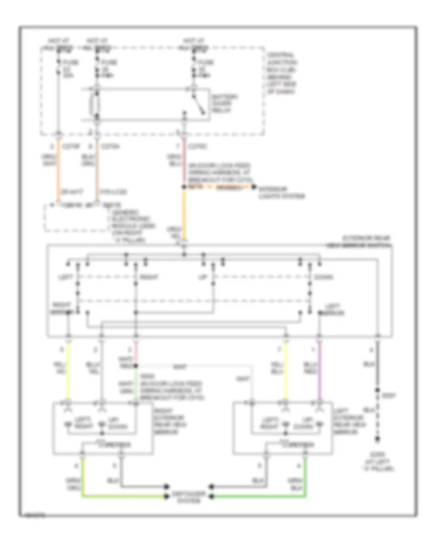
POWER MIRRORS Power Mirrors Wiring Diagram for Ford Focus SVT 2004 List of elements for Power Mirrors Wiring Diagram for Ford Focus SVT 2004: 29 29-aa17 31s-lc22 Battery saver relay C201c C201e C270a C270c C270f Central junction box (cjb) (behind left side of dash) Defogger system Down Exterior rear view mirror switch Fuse 20a Fuse 7.5a G200 (at left ``a" pillar) Generic electronic module (gem) (on right ``a" pillar) Heater Hot at all times Interior lights system Left Left exterior rear view mirror Left mirror Left/ right Right Right exterior rear view mirror Right mirror S597 Up/ down Wiring harness, at breakout for c510)
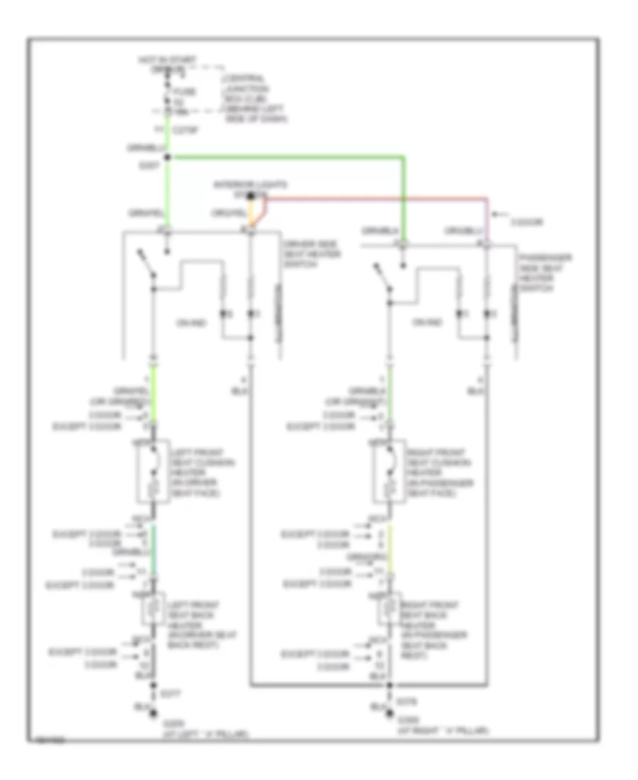
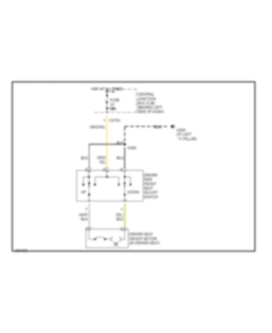
POWER SEATS Heated Seats Wiring Diagram for Ford Focus SVT 2004 List of elements for Heated Seats Wiring Diagram for Ford Focus SVT 2004: 21 3 door C270f Central junction box (cjb) (behind left side of dash) Driver side seat heater switch Except 3 door Except 3 door 3 door Fuse 15a G200 (at left ``a" pillar) G300 (at right ``a" pillar) Hot in start or run Illumination Interior lights system Left front seat back heater (in driver seat back rest) Left front seat cushion heater (in driver seat face) Nca On ind Passenger side seat heater switch illumination Right front seat back heater (in passenger seat back rest) Right front seat cushion heater (in passenger seat face) S357 S377 Power Seat Wiring Diagram for Ford Focus SVT 2004 List of elements for Power Seat Wiring Diagram for Ford Focus SVT 2004: 9 C270a Central junction box (cjb) (behind left side of dash) Down Driver seat height motor (in driver seat) Driver side front seat adjust switch Fuse 20a G200 (at left ``a" pillar) Hot at all times S382
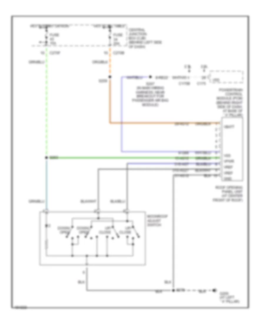
POWER TOP/SUNROOF Power Top/Sunroof Wiring Diagram for Ford Focus SVT 2004 List of elements for Power Top/Sunroof Wiring Diagram for Ford Focus SVT 2004: 33 15-ag12 2.0l 2.3l 29-ag12 31-ag12 31s-ag27 31s-ag7 8-gb8 8-re22 C175 C175b C270b C270f Central junction box (cjb) (behind left side of dash) Down/ open Fuse 15a Fuse 20a G200 (at left ``a" pillar) Gnd Hot at all times Hot in start or run Moonroof adjust switch Powertrain control module (pcm) (behind right side of dash, at base of ``a" pillar) Roof opening panel unit (at center front of roof) S207 (in main wiring harness, near breakout for passenger air bag module) S253 S259 S270 Up/ close Vbatt Vpwr Vref Vss
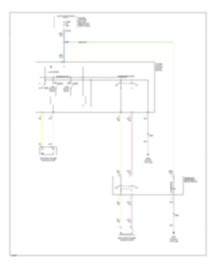
POWER WINDOWS Power Windows Wiring Diagram, with Rear Power Windows for Ford Focus SVT 2004 List of elements for Power Windows Wiring Diagram, with Rear Power Windows for Ford Focus SVT 2004: 34 (in door lock feed wiring harness (14014), near breakout for driver's seat) s358 (in door lock jumper wiring harness (14a584), near breakout for c510) s501 C270e C504a C504b Central junction box (cjb) (behind left side of dash) Driver switch From s356 (diagram 1 of 1) Fuse 25a G200 (at left ``a" pillar) G300 (at right ``a" pillar) Hot in start or run Illumination Left front power window motor Left rear power window motor Left rear switch Left rear window adjust switch Lock Master window adjust switch One- touch down One-touch window relay (in driver's front door, behind trim panel) Pass switch Passenger side window adjust switch Rest Right front power window motor Right rear power window motor Right rear switch Right rear window adjust switch S356 S377 S378 S597 S694 To passenger side window adjust switch (diagram 1 of 1) Power Windows Wiring Diagram, without Rear Power Windows for Ford Focus SVT 2004 List of elements for Power Windows Wiring Diagram, without Rear Power Windows for Ford Focus SVT 2004: 19 (at right ``a" pillar) C270e Central junction box (cjb) (behind left side of dash) Driver switch Fuse 25a G200 (at left ``a" pillar) G300 Hot in start or run Illumination Left front power window motor Master window adjust switch One- touch down Passenger side window adjust switch Passenger switch Rest Right front power window motor S356 S597 S694
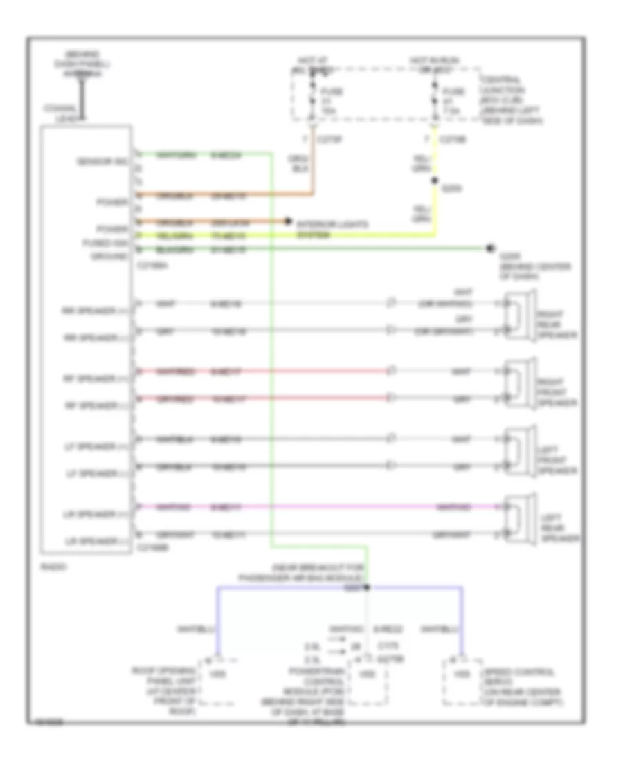
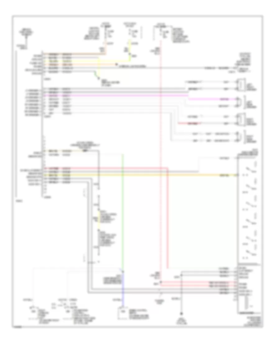
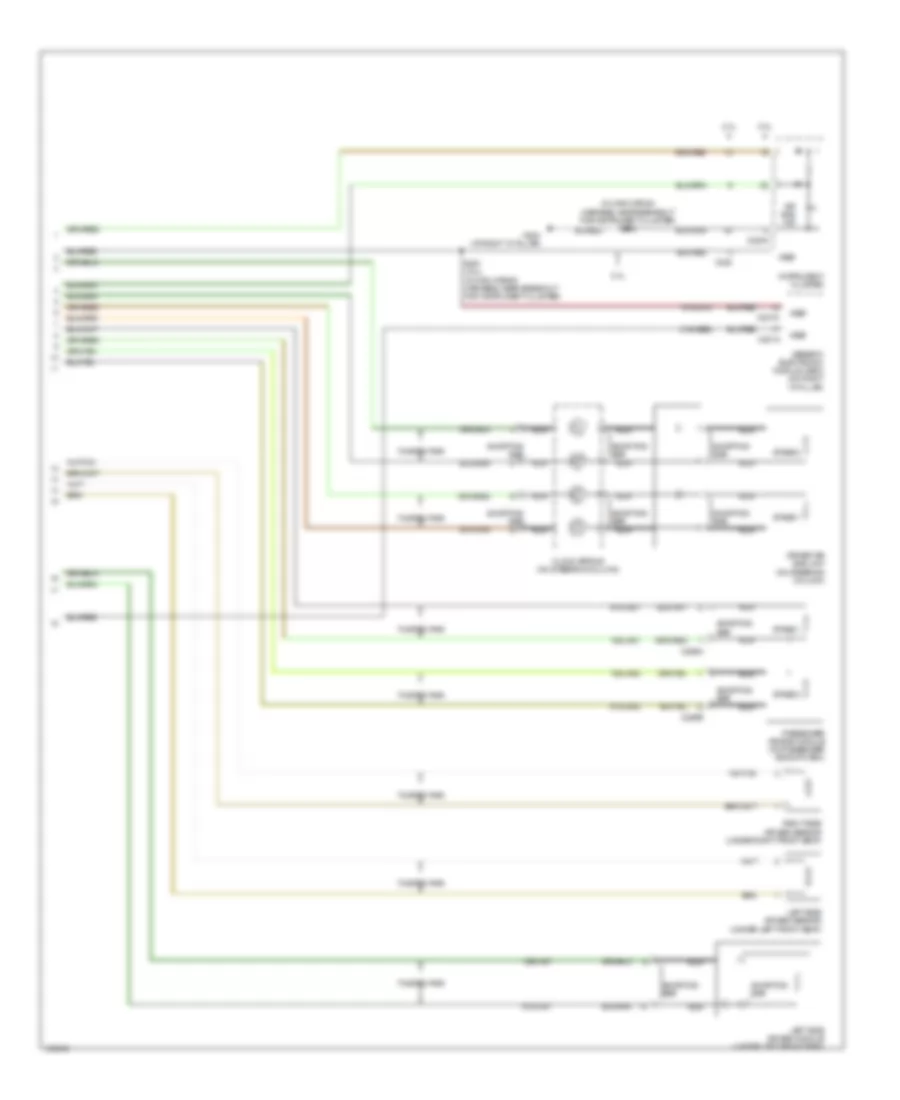
RADIO Radio Wiring Diagram, Bosch for Ford Focus SVT 2004 List of elements for Radio Wiring Diagram, Bosch for Ford Focus SVT 2004: 53 (behind dash panel) antenna (near breakout for passenger air bag module) s207 10-md10 10-md11 10-md17 10-md18 2.0l 2.3l 29-md15 29s-lk34 75-md15 8-md10 8-md11 8-md17 8-md18 8-md24 91-md15 C175 C175b C2188a C2188b C270b C270f Central junction box (cjb) (behind left side of dash) Coaxial lead Fuse 15a Fuse 7.5a Fused ign G205 (behind center of dash) Ground Hot at all times Hot in run or acc Interior lights system Left front speaker Left rear speaker Lf speaker (+) Lf speaker (-) Lr speaker (+) Lr speaker (-) Power Powertrain control module (pcm) (behind right side of dash, at base of "a" pillar) Radio Rf speaker (+) Rf speaker (-) Right front speaker Right rear speaker Roof opening panel unit (at center front of roof) Rr speaker (+) Rr speaker (-) S250 Sensor sig Speed control servo (on rear center of engine compt) Vss Radio Wiring Diagram, Except Bosch for Ford Focus SVT 2004 List of elements for Radio Wiring Diagram, Except Bosch for Ford Focus SVT 2004: 83 (behind dash panel) antenna (in main wiring harness, near breakout for radio) s299 (on right "a" pillar) generic electronic module (gem) (svt) radio remote control switch 1-md23 10-md10 10-md11 10-md17 10-md18 2-md23 2.0l 2.3l 29-md15 29s-lk34 31s-gl15 75-md15 8-md10 8-md11 8-md17 8-md18 8-md19 8-md24 8-md26 9-md23a 9-md26 91-md15 91-md34 Audio sig (+) Audio sig (-) Battery junction box (bjb) (in left rear corner of engine compt) C175 C175b C201c C270b C270f C290a C290b C290c Central junction box (cjb) (behind left side of dash) Coaxial lead Fuse 15a Fuse 30a Fuse 7.5a Fused ign G201 (at left "a" pillar) G205 (behind center of dash) Ground Hot at all times Hot in run or acc Interior lights system Left front speaker Left rear speaker Lf speaker (+) Lf speaker (-) Lr speaker (+) Lr speaker (-) Nca Power Powertrain control module (pcm) (behind right side of dash, at base of "a" pillar) Radio Rf speaker (+) Rf speaker (-) Right front speaker Right rear speaker Roof opening panel unit (at center front of roof) Rr speaker (+) Rr speaker (-) S205 (in door lock feed wiring harness, at breakout for c210) nca S207 (near breakout for passenger air bag module) S250 S403 S404 Sens sig rtn Sensor sig Shield Speed control servo (on rear center of engine compt) Subwoofer Subwoofer amplifier (in luggage compartment) Sw en/ clip detect Sw en/clip detect Twisted pair Vehicle alarm Vss
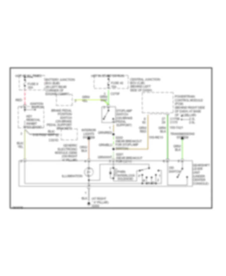
SHIFT INTERLOCK Shift Interlock Wiring Diagram for Ford Focus SVT 2004 List of elements for Shift Interlock Wiring Diagram for Ford Focus SVT 2004: 28 (at right ``a" pillar) g202 15s-re13 2.3l 2.0l 31s-ta32 Battery junction box (bjb) (in left rear corner of engine compt) Brake pedal position switch (on brake pedal support bracket) C175b c175 C201d C270f Central junction box (cjb) (behind left side of dash) Fuse 42 15a Fuse 8 30a Gearshift lever unit (under center console) Generic electronic module (gem) (on right ``a" pillar) Hot at all times Hot in start or run Ignition switch Illumination Interior lights system Key removal inhibit solenoid O/d switch Park interlock solenoid Powertrain control module (pcm) (behind right side of dash, at base of ``a" pillar) Red S267 (near breakout for c211) Stoplamp switch (on brake pedal support) Switch) Transmissions system
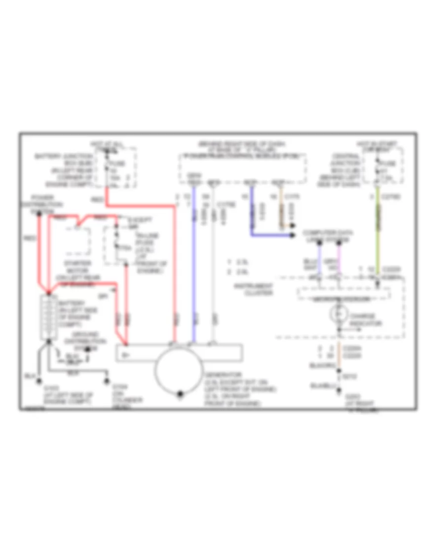
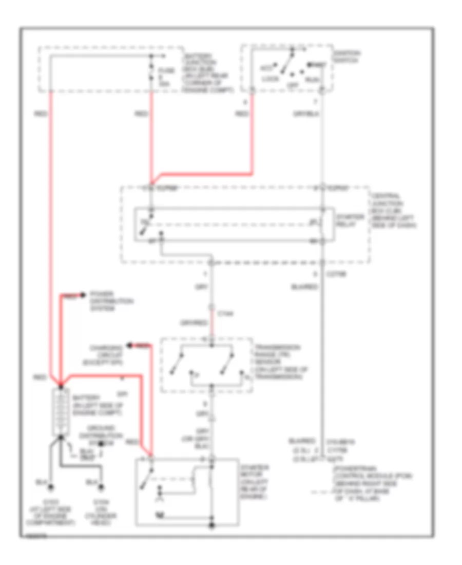
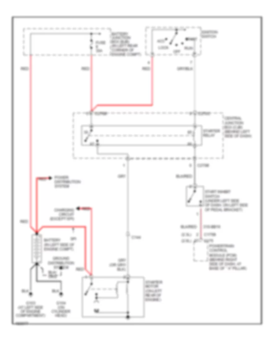
STARTING/CHARGING Charging Wiring Diagram for Ford Focus SVT 2004 List of elements for Charging Wiring Diagram for Ford Focus SVT 2004: 38 (behind right side of dash, at base of ``a" pillar) powertrain control module (pcm) 175a 2.0l 2.3l Battery (in left side of engine compt) Battery junction box (bjb) (in left rear corner of engine compt) C175 C175e C220a C2220 C270d Central junction box (cjb) (behind left side of dash) Charge indicator Computer data lines system Distribution Except spi Fuse 10a 1a Fuse 7.5a G103 (at left side of engine compt) G104 (on cylinder head) G203 (at right ``a" pillar) Gen/ fdc Generator (2.0l except svt: on left front of engine) (2.3l: on right front of engine) Gfs Ground distribution system Hot at all times Hot in start or run In-line fuse (2.3l) (at front of engine) Instrument cluster Microprocessor Power Red S212 Scp + Scp - Spi Starter motor (on left rear of engine) System Starting Wiring Diagram, A/T for Ford Focus SVT 2004 List of elements for Starting Wiring Diagram, A/T for Ford Focus SVT 2004: 29 (2.0l) (2.3l) 31s-bb16 Acc Battery (in left side of engine compt) Battery junction box (bjb) (in left rear corner of engine compt) C144 C175 C175b C270b C270c Central junction box (cjb) (behind left side of dash) Charging circuit (except spi) Fuse 30a G103 (at left side of engine compartment) G104 (on cylinder head) Ground distribution system Ignition switch Lock Off Power distribution system Powertrain control module (pcm) (behind right side of dash, at base of ``a" pillar) Red Run Spi Start Starter motor (on left rear of engine) Starter relay Transmission range (tr) sensor (on left side of transmission) n Starting Wiring Diagram, M/T for Ford Focus SVT 2004 List of elements for Starting Wiring Diagram, M/T for Ford Focus SVT 2004: 29 (2.0l) (2.3l) 31s-bb16 Acc Battery (in left side of engine compt) Battery junction box (bjb) (in left rear corner of engine compt) C144 C175 C175b C270b C270c Central junction box (cjb) (behind left side of dash) Charging circuit (except spi) Fuse 30a G103 (at left side of engine compartment) G104 (on cylinder head) Ground distribution system Ignition switch Lock Off Power distribution system Powertrain control module (pcm) (behind right side of dash, at base of ``a" pillar) Red Run Spi Start Start inhibit switch (under left side of dash, on left side of pedal bracket) Starter motor (on left rear of engine) Starter relay
SUPPLEMENTAL RESTRAINTS Supplemental Restraints Wiring Diagram (1 of 2) for Ford Focus SVT 2004 List of elements for Supplemental Restraints Wiring Diagram (1 of 2) for Ford Focus SVT 2004: 34 (in main wiring harness, near breakout for instrument cluster) s212 15s-ja31 15s-ja32 15s-ja37 2.0l 2.3l 31s-ge52 91s-ja13 91s-ja31 91s-ja32 91s-ja37 Air bag ind C201a C201d C220 C220a C256a C256b Clock spring (on steering column) Driver air bag unit (on steering column) G203 (at right "a" pillar) Generic electronic module (gem) (on right "a" pillar) Instrument cluster Left side air bag module (under left front seat) Left side air bag sensor (under left front seat) Nca Passenger air bag module (on passenger side of dash) Right side air bag sensor (under right front seat) S291 (2.3l) (in main wiring harness, near breakout for instrument cluster) Shorting bar Stage 1 Stage 2 Twisted pair Vref Supplemental Restraints Wiring Diagram (2 of 2) for Ford Focus SVT 2004 List of elements for Supplemental Restraints Wiring Diagram (2 of 2) for Ford Focus SVT 2004: 65 (in door lock feed wiring harness, near breakout for restraints control module) s383 15-ja10 15s-ja31 15s-ja32 15s-ja33 15s-ja34 15s-ja37 15s-ja38 15s-ja48 15s-ja8 3 door 31s-ge52 7-ja53 8-ee7 8-ja39 8-ja40 8-ja9 9-ja39 9-ja40 9-ja53 9-ja54 9-ja55 9-ja9 91s-ja13 91s-ja14 91s-ja31 91s-ja32 91s-ja33 91s-ja34 91s-ja37 91s-ja38 91s-ja48 91s-ja8 C2041a C2041b C270d C270e C3000 C3001 C311a C311b C312b C312c Central junction box (cjb) (behind left side of dash) Computer data lines system Driver safety belt retractor pretensioner (at driver seat) Driver seat belt buckle sensor (near driver seat) Driver seat track position sensor (under driver seat) Except 3 door Forward crash sensor (at front center of vehicle) Fuse 7.5a Hot in start or run Iso Nca Passenger safety belt retractor pretensioner (near passenger seat) Passenger seat belt buckle sensor (near passenger seat) Pin shorting bars engaged when module connector is disconnected from harness (shorting bars are connected between pins: 17-18, & 29-30 c2041a 7-8, 9-10, 11-12 & 13-19 c2041b) Restraints control module (under center console) Right side air bag module (under right front seat) Shorting bar Sig rtn Sw gnd Twisted pair Vpwr Vref
TRANSMISSION
2.0L DOHC 2.0L DOHC, A/T Wiring Diagram for Ford Focus SVT 2004 List of elements for 2.0L DOHC, A/T Wiring Diagram for Ford Focus SVT 2004: 124 (8-rj33) (engine control harn, near breakout to battery) (engine ctrl harn, near breakout for a/c compressor cycling switch) (engine ctrl harn, near breakout for coil on plug 2) s154 (engine ctrl harn, near breakout to c211) (engine ctrl harn, near breakout to pcm) s268 (engine ctrl sensor harn, near breakout to c1026) (fuel shutoff harn, near breakout to intake system) s197 (in main harn, near breakout for instrument cluster) (main harn, near breakout to stop light switch) (on left side of transmission) transmission range sensor (on top of transmission) turbine shaft speed (tss) sensor 1 pos 15-re8 15-re8a 15s-re13 15s-ta17 15s-ta21 15s-ta23 15s-ta24 15s-ta37 15s-ta38a 15s-ta40 15s-ta41 15s-ta42 15s-ta63 15s-ta64 15s-ta65 2 pos 29-re14 30-re8 4-eg9 5-eg9 7-re8 8-rj17 8-rj22 8-rj28 8-rj29 8-rj5 8-ta27 8-ta36 9-re8 9-re8a 9-rj22 9-rj29 91-re8 91-re8a 91-re8c 91s-ta17 Back-up lamps Battery junction box (left rear engine compt) Brake pedal position switch Central junction box (behind left side of dash) Data link connector (partial) (under left side of dash, on central junction box) Dataline Diode Dpos Ect/cht Engine controls Engine controls system Engine coolant temperature sensor (sohc) cylinder head temperature Exterior lights system Fuse 10a Fuse 15a Fuse 20a G103 (left side of eng compt) G103 (left side of engine compt) Gearshift lever unit Ground Hot at all times Hot in run or start Ign power Instrument cluster Kapwr Maf Maf return Maf sig Mass air- flow (maf) sensor (left side of engine compt) Nca O/d off switch Oss Output shaft speed sensor (right side of trans) Pca Pca trans unit Pnp Power hold relay Powertrain control module (pcm) (behind right side of dash, at base of "a" pillar) R pos Red Ref voltage Return S117 S118 S159 S163 S187 S198 S216 S217 S252 S267 (engine ctrl harn, near breakout to c211) S275 Sensor (dohc) (on cylinder head) Sig return Ssa Ssa trans unit Ssb Ssb trans unit Ssc Ssc trans unit Ssd Ssd trans unit Sse Sse trans unit Stoplamp sw Stoplamp switch (right side of brake pedal bracket) Tc sw Tft Tft sens Throttle position (tp) sensor (on throttle body) Tps signal Transmission hardware unit Tss sig Vss
2.0L SOHC 2.0L SOHC, A/T Wiring Diagram for Ford Focus SVT 2004 List of elements for 2.0L SOHC, A/T Wiring Diagram for Ford Focus SVT 2004: 124 (8-rj33) (engine control harn, near breakout to battery) (engine ctrl harn, near breakout for a/c compressor cycling switch) (engine ctrl harn, near breakout for coil on plug 2) s154 (engine ctrl harn, near breakout to c211) (engine ctrl harn, near breakout to pcm) s268 (engine ctrl sensor harn, near breakout to c1026) (fuel shutoff harn, near breakout to intake system) s197 (in main harn, near breakout for instrument cluster) (main harn, near breakout to stop light switch) (on left side of transmission) transmission range sensor (on top of transmission) turbine shaft speed (tss) sensor 1 pos 15-re8 15-re8a 15s-re13 15s-ta17 15s-ta21 15s-ta23 15s-ta24 15s-ta37 15s-ta38a 15s-ta40 15s-ta41 15s-ta42 15s-ta63 15s-ta64 15s-ta65 2 pos 29-re14 30-re8 4-eg9 5-eg9 7-re8 8-rj17 8-rj22 8-rj28 8-rj29 8-rj5 8-ta27 8-ta36 9-re8 9-re8a 9-rj22 9-rj29 91-re8 91-re8a 91-re8c 91s-ta17 Back-up lamps Battery junction box (left rear engine compt) Brake pedal position switch Central junction box (behind left side of dash) Data link connector (partial) (under left side of dash, on central junction box) Dataline Diode Dpos Ect/cht Engine controls Engine controls system Engine coolant temperature sensor (sohc) cylinder head temperature Exterior lights system Fuse 10a Fuse 15a Fuse 20a G103 (left side of eng compt) G103 (left side of engine compt) Gearshift lever unit Ground Hot at all times Hot in run or start Ign power Instrument cluster Kapwr Maf Maf return Maf sig Mass air- flow (maf) sensor (left side of engine compt) Nca O/d off switch Oss Output shaft speed sensor (right side of trans) Pca Pca trans unit Pnp Power hold relay Powertrain control module (pcm) (behind right side of dash, at base of "a" pillar) R pos Red Ref voltage Return S117 S118 S159 S163 S187 S198 S216 S217 S252 S267 (engine ctrl harn, near breakout to c211) S275 Sensor (dohc) (on cylinder head) Sig return Ssa Ssa trans unit Ssb Ssb trans unit Ssc Ssc trans unit Ssd Ssd trans unit Sse Sse trans unit Stoplamp sw Stoplamp switch (right side of brake pedal bracket) Tc sw Tft Tft sens Throttle position (tp) sensor (on throttle body) Tps signal Transmission hardware unit Tss sig Vss
2.3L 2.3L, A/T Wiring Diagram for Ford Focus SVT 2004 List of elements for 2.3L, A/T Wiring Diagram for Ford Focus SVT 2004: 125 (engine control harn, near breakout for a/c compressor cycling switch) (engine control harn, near breakout to c122) (engine control harn, near breakout to c179) (engine ctrl harn, near breakout for coil on plug 2) (engine ctrl harn, near breakout pcm) (engine ctrl harn, near breakout to c211) (engine ctrl sensor ext harn, near breakout to c1026) s187 (in junction box wiring harn, near battery junction box) s117 (in main wiring harn, near breakout for instrument cluster) (main harn, near breakout for stop lamp switch) (on left side of transmission) transmission range sensor 1 pos 15-re8 15-re8a 15s-re13 15s-ta17 15s-ta21 15s-ta23 15s-ta24 15s-ta37 15s-ta38a 15s-ta40 15s-ta41 15s-ta42 15s-ta63 15s-ta64 15s-ta65 2 pos 29-re14 30-re8 4-ec7 5-ec7 7-re8 8-rj17 8-rj22 8-rj28 8-rj29 8-rj33 8-ta27 8-ta36 9-da1 9-re8 9-rj22 9-rj29 91-re8 91-re8a 91-re8b 91s-ta17 Back-up lamps Battery junction box (left rear corner of engine compt) Brake pedal position switch C175b C175e C175t Central junction box (behind left side of dash) Cylinder head temperature sensor (on cylinder Data link connector (partial) (under left side of dash, on central junction box) Dataline Diode Dpos Ect/cht Engine controls system Exterior lights system Fuse 10a Fuse 15a Fuse 20a G103 (at left side of eng compt) G103 (left side of engine compt) Gearshift lever unit Ground Head) Hot at all times Hot in run or start Ign power Kapwr Maf Maf return Maf sig Mass air- flow (maf) sensor (left side of engine compt) O/d switch Oss Output shaft speed sensor (rear of transmission) Pca Pca trans unit Pnp Power hold relay Powertrain control module (pcm) (behind right side of dash, at base of "a" pillar) R pos Red Ref voltage Return S118 S154 S159 S162 S163 S197 S201 S211 S252 S267 (engine ctrl harn, near breakout to c211) S275 S293 Sig return Ssa Ssa trans unit Ssb Ssb trans unit Ssc Ssc trans unit Ssd Ssd trans unit Sse Sse trans unit Stoplamp sw Stoplamp switch (right side of brake pedal bracket) Tc sw Tft Tft sens Throttle position (tp) sensor (on throttle body) Tps signal Transmission hardware unit Tss sig Turbine shaft speed (tss) sensor (on top of transmission) Vss
TRUNK, TAILGATE, FUEL DOOR Trunk, Tailgate, Fuel Door Wiring Diagram, Sedan & Hatchback Early Production for Ford Focus SVT 2004 List of elements for Trunk, Tailgate, Fuel Door Wiring Diagram, Sedan & Hatchback Early Production for Ford Focus SVT 2004: 31 29-aa17 29-dk20 31-dk20 31s-gl20 31s-gl27 32-aa27 8s-aa30 91-dk20 C201a C201b C201c C201d C201e C270f Central junction box (cjb) (behind left side of dash) Fuse 15a Fuse 20a G203 (at right "a" pillar) G204 (at left "a" pillar) G302 G402 (at left rear of luggage compt) Generic electronic module (gem) (on right "a" pillar) Hot at all times Interior lights system Liftgate/ decklid latch assembly (in liftgate) Liftgate/ decklid release switch Nca S206 S212 S230 (near breakout for data link connector) S496 Trunk, Tailgate, Fuel Door Wiring Diagram, Sedan & Hatchback Late Production for Ford Focus SVT 2004 List of elements for Trunk, Tailgate, Fuel Door Wiring Diagram, Sedan & Hatchback Late Production for Ford Focus SVT 2004: 25 31s-gl20 31s-gl27 32-aa51 C201a C201b C270a C270b C270h Central junction box (cjb) (behind left side of dash) Decklid relay Fuse 20a Fuse 25a G204 (at left "a" pillar) G402 (at left rear of luggage compt) Generic electronic module (gem) (on right "a" pillar) Hot at all times Interior lights system Luggage compartment lid release relay (in decklid) Luggage compartment lid release solenoid (in decklid) Luggage compartment lock cylinder switch (in decklid) S206 S259 S496 Vpwr Vref Trunk, Tailgate, Fuel Door Wiring Diagram, Wagon for Ford Focus SVT 2004 List of elements for Trunk, Tailgate, Fuel Door Wiring Diagram, Wagon for Ford Focus SVT 2004: 33 (near breakout for data link connector) s230 29-aa17 29-dk20 31-dk20 31s-gl20 31s-gl27 32-aa27 8s-aa30 91-dk20 C201a C201b C201c C201d C201e C270f Central junction box (cjb) (behind left side of dash) Exterior liftgate/ decklid release switch Fuse 15a Fuse 20a G203 (at right "a" pillar) G204 (at left "a" pillar) G302 G400 (in liftgate) Generic electronic module (gem) (on right "a" pillar) Hot at all times Interior lights system Liftgate/ decklid anti-theft inhibit switch (in liftgate) Liftgate/ decklid latch assembly (in liftgate) Liftgate/ decklid release switch Nca S206 S212 S496
WARNING SYSTEMS Warning Systems Wiring Diagram for Ford Focus SVT 2004 List of elements for Warning Systems Wiring Diagram for Ford Focus SVT 2004: 89 (a/t) (in main wiring harness, near breakout for g203) s215 2.0l 2.3l 29-aa17 29-dk20 29s-le18 3 door 30s-ta31a 31-dk20 31s-aa7 31s-ge49 31s-ge52 31s-gl12 31s-gl16 31s-gl19 31s-gl20 31s-gl7 31s-gl9 31s-ta32 7-ja53 9-ja54 9-ja55 91-dk20 A/t C201a C201b C201c C201d C201e C2041a C220a C2220 C270d C270f Central junction box (cjb) (behind left side of dash) Door ajar sig Door open indicator Door open sig Driver seat belt buckle sensor (near driver seat) Driver seat belt sig Driver side front door ajar switch (on left "b" pillar) Driver side rear door ajar switch (on left "c" pillar) Engine compartment switch (in front center of engine compt) Engine compt sw in Except 3 door Exterior lights Fuse 15a Fuse 20a Fuse 7.5a G100 (at left front of engine compt) G200 (at left "a" pillar) G203 (at right "a" pillar) G300 (at right "a" pillar) G302 G400 (in liftgate) Generic electronic module (gem) (on right "a" pillar) Ground Head Hot at all times Hot in start or run Ignition switch Instrument cluster Key in ignition switch Key in sw Key removal inhibit solenoid Liftgate ajar sw in Liftgate/ decklid latch assembly (in decklid) Light switch Nca Off Park Pass seat belt sig Passenger seat belt buckle sensor (near passenger seat) Passenger side front door ajar switch (on right "b" pillar) Passenger side rear door ajar switch (on right "c" pillar) Restraints control module (under center console) S121 S212 S377 S378 S383 (near breakout for restraints control module) S496 Safety belt indicator Seat belt common Seat belt sig Shift interlock system Switched ground Vbatt
WIPER/WASHER Intermittent Wiper/Washer Wiring Diagram for Ford Focus SVT 2004 List of elements for Intermittent Wiper/Washer Wiring Diagram for Ford Focus SVT 2004: 41 32-ka35 32-ka6 32-ka9a 33-ka6 8-ka18 8-ka19 91-dk20 91s-ka12 C201c C201d C201e C270a C270c C270f Central junction box (cjb) (behind left side of dash) Fuse 20a G100 (at left front of engine compartment) G203 (at right "a" pillar) G204 (at left "a" pillar) Generic electronic module (gem) (on right "a" pillar) High Hot in start or run Int Low Off Off int Park Run S121 S206 S212 Single Two-way washer pump motor (on bottom of washer fluid reservoir) Variable intermittent wipe W/o rear wiper W/rear wiper Washer on Windshield wiper motor (on top center of firewall) Windshield wiper relay Wiper on Wiper/washer switch Rear Washer/Wiper Wiring Diagram for Ford Focus SVT 2004 List of elements for Rear Washer/Wiper Wiring Diagram for Ford Focus SVT 2004: 30 32-ka35 32-ka6 33-ka6 91-dk20 91s-ka29 C201d C201e C270b C270c C270f Central junction box (cjb) (behind left side of dash) Front washer on Fuse 15a Fuse 20a G203 (at right "a" pillar) G204 (at left "a" pillar) Generic electronic module (gem) (on right "a" pillar) Hot in start or run Off Power tops system Rear washer on Rear window wiper motor (wagon: in liftgate) (3/5 door: in liftgate, behind trim) Rear wiper on Rear wiper relay S206 S212 S253 (w/ roof opening panel) Two-way washer pump motor (on bottom of washer fluid reservoir) Windshield wiper motor (on top center of firewall) Wiper/ washer switch