Diagram sections — 29 (64 total)
AIR CONDITIONING ANTI-LOCK BRAKES ANTI-THEFT BODY CONTROL MODULES COMPUTER DATA LINES COOLING FAN CRUISE CONTROL DEFOGGERS ENGINE PERFORMANCE EXTERIOR LIGHTS GROUND DISTRIBUTION HEADLIGHTS HORN INSTRUMENT CLUSTER INTERIOR LIGHTS POWER DISTRIBUTION POWER DOOR LOCKS POWER MIRRORS POWER SEATS POWER TOP/SUNROOF POWER WINDOWS RADIO SHIFT INTERLOCK STARTING/CHARGING SUPPLEMENTAL RESTRAINTS TRANSMISSION TRUNK, TAILGATE, FUEL DOOR WARNING SYSTEMS WIPER/WASHER
AIR CONDITIONING
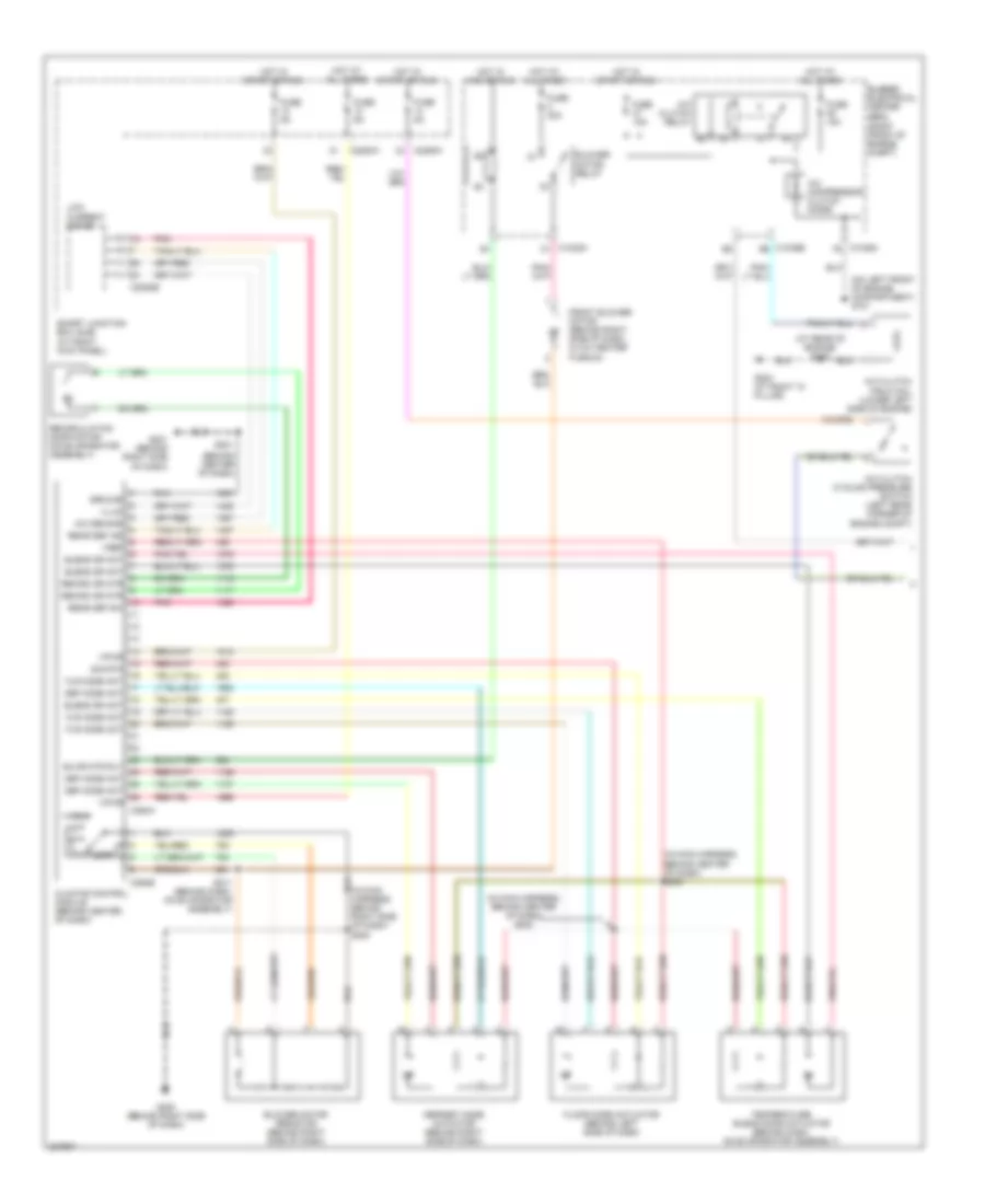
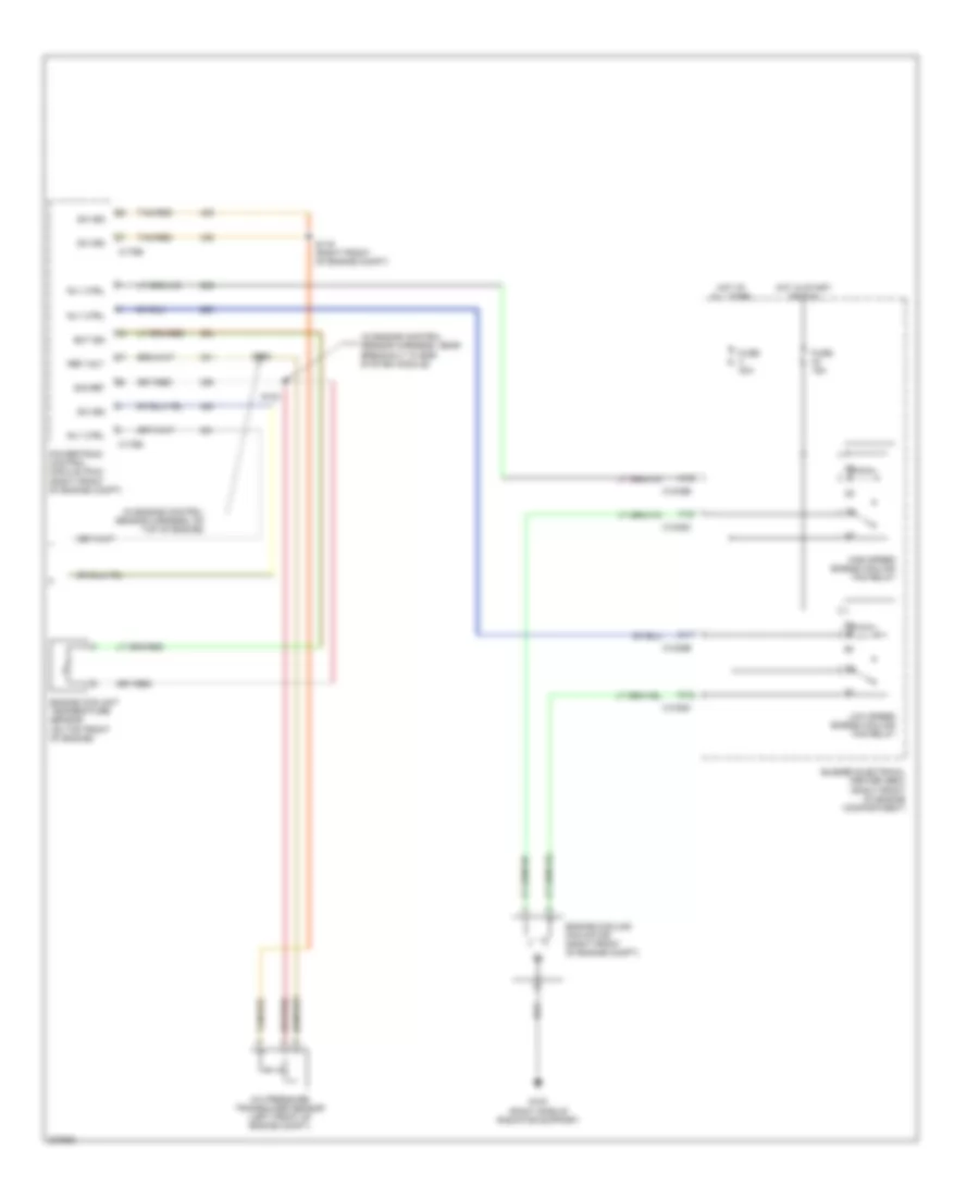
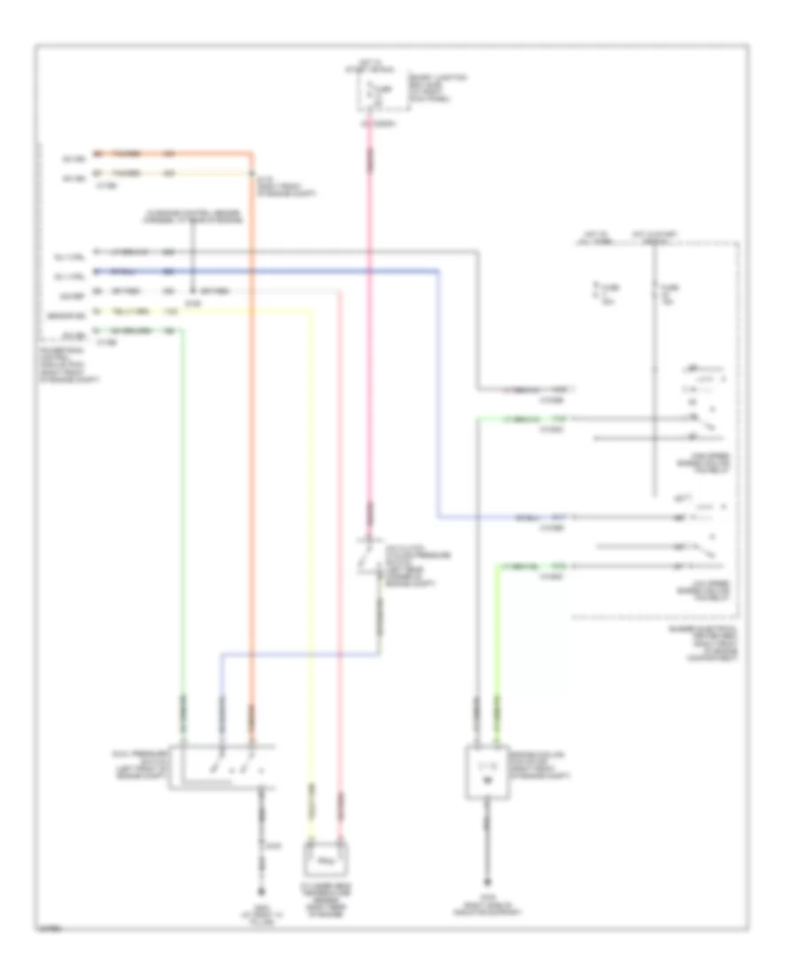
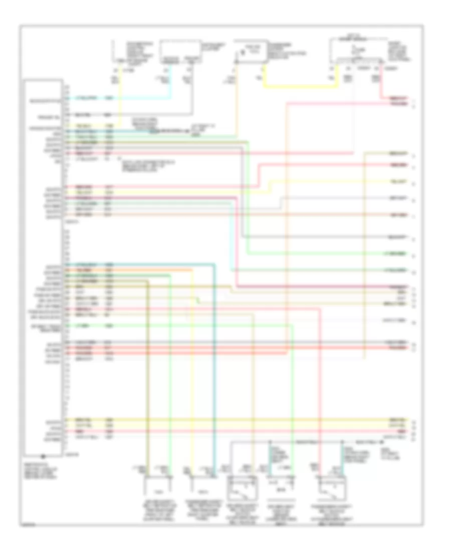
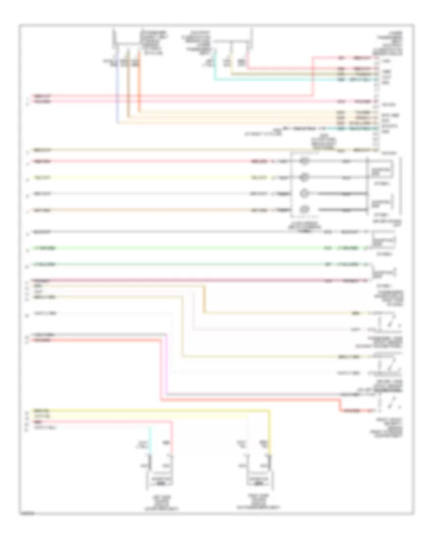
4.0L 4.0L, Manual A/C Wiring Diagram (1 of 2) for Ford Mustang GT 2006 List of elements for 4.0L, Manual A/C Wiring Diagram (1 of 2) for Ford Mustang GT 2006: 57 (at rear of engine) s100 (behind center of dash) (in main harness, behind center of dash) s203 (in main harness, behind center of dash) s202 (in main harness, behind right side of dash) s200 (on left front of engine compartment) g101 (right front of engine compt) A/c clutch cycling pressure switch (left rear corner of engine compt) A/c clutch field coil (lower left side of engine) A/c clutch relay A/c compressor clutch diode A/c demand Blend dr act Blower motor relay Blower motor resistor (behind right side of dash) Blwr mtr rly Bussed electrical center (bec) C1035a c1 C1035b b6 C1035c f5 C2280a C2280b C2280h C294a C294b Climate control module (behind center of dash) Def mode act Defrost mode actuator (behind right side of dash) Floor mode actuator (behind left side of dash) Flr mode act Front blower motor (behind right side of dash, in a/c heater plenum) Fuse 15a Fuse 30a Fuse 5a G200 (behind right side of dash) G201 (behind right side of dash) G203 (at right "a" pillar) Ground High Hot at all times Hot in acc or run Hot in start or run Illum Low Low current board Pnk Rear def ind Rear def sw Recirc dr mtr Recirculation door motor (on evaporator assembly) S201 S211 (behind dash, on evaporator assembly) Sig rtn Smart junction box (sjb) (at right kick panel) Temperature blend door actuator (behind dash, on evaporator assembly) Vpwr Vref 4.0L, Manual A/C Wiring Diagram (2 of 2) for Ford Mustang GT 2006 List of elements for 4.0L, Manual A/C Wiring Diagram (2 of 2) for Ford Mustang GT 2006: 31 (in engine control sensor harness, near breakout to egr system module) (in engine control sensor harness, on top of engine) A/c pressure transducer sensor (left front of engine compt) A12 Bussed electrical center (bec) (right front of engine compartment) C1035b C1035c C11 C12 C175b C175e Ect sig Engine coolant temperature sensor (on top front of engine) Engine cooling fan motor (right front of engine compt) F12 Fuse 15a Fuse 40a G100 (right side of radiator support) High speed engine cooling fan relay Hot at all times Hot in start or run Low speed engine cooling fan relay Powertrain control module (pcm) (right front of engine compt) Ref volt Rly ctrl S102 S103 S116 (right front of engine compt) Sig ret Sw sig Tan/red
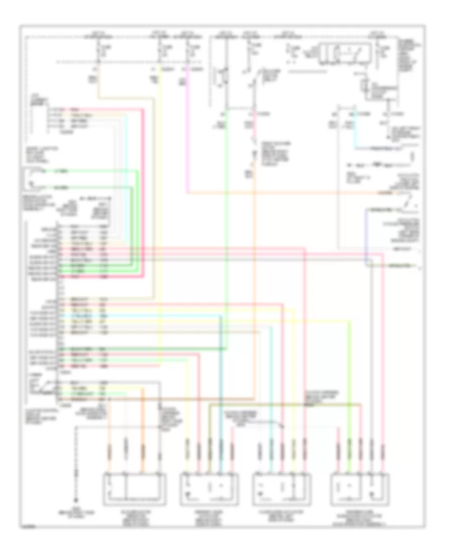
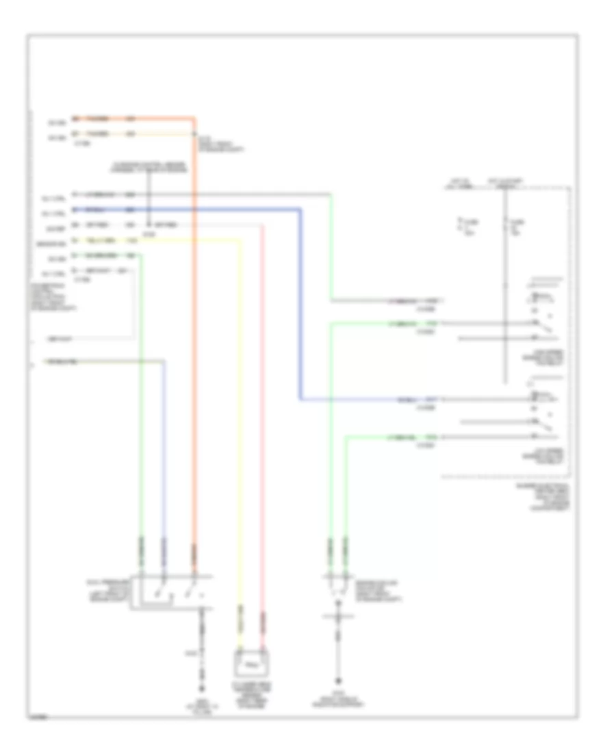
4.6L 4.6L, Manual A/C Wiring Diagram (1 of 2) for Ford Mustang GT 2006 List of elements for 4.6L, Manual A/C Wiring Diagram (1 of 2) for Ford Mustang GT 2006: 57 (behind center of dash) (in main harness, behind center of dash) s203 (in main harness, behind center of dash) s202 (in main harness, behind right side of dash) s200 (on left front of engine compartment) g101 (right front of engine compt) A/c clutch cycling pressure switch (left rear corner of engine compt) A/c clutch field coil (lower left side of engine) A/c clutch relay A/c compressor clutch diode A/c demand Blend dr act Blower motor relay Blower motor resistor (behind right side of dash) Blwr mtr rly Bussed electrical center (bec) C1035a c1 C1035b b6 C1035c f5 C2280a C2280b C2280h C294a C294b Climate control module (behind center of dash) Def mode act Defrost mode actuator (behind right side of dash) Floor mode actuator (behind left side of dash) Flr mode act Front blower motor (behind right side of dash, in a/c heater plenum) Fuse 15a Fuse 30a Fuse 5a G200 (behind right side of dash) G201 (behind right side of dash) G203 (at right "a" pillar) Ground High Hot at all times Hot in acc or run Hot in start or run Illum Low Low current board Pnk Rear def ind Rear def sw Recirc dr mtr Recirculation door motor (on evaporator assembly) S100 S201 S211 (behind dash, on evaporator assembly) Sig rtn Smart junction box (sjb) (at right kick panel) Temperature blend door actuator (behind dash, on evaporator assembly) Vpwr Vref 4.6L, Manual A/C Wiring Diagram (2 of 2) for Ford Mustang GT 2006 List of elements for 4.6L, Manual A/C Wiring Diagram (2 of 2) for Ford Mustang GT 2006: 30 (in engine control sensor harness, at rear of engine) A12 Bussed electrical center (bec) (right front of engine compartment) C1035b C1035c C11 C12 C175b C175e Cylinder head temperature sensor (right rear of engine) Dual pressure switch (left front of engine compt) Engine cooling fan motor (right front of engine compt) F12 Fuse 15a Fuse 40a G100 (right side of radiator support) G203 (at right "a" pillar) High speed engine cooling fan relay Hot at all times Hot in start or run Low speed engine cooling fan relay Powertrain control module (pcm) (right front of engine compt) Rly ctrl S100 S106 S116 (right front of engine compt) Sensor sig Sig ret Sw sig Tan/red
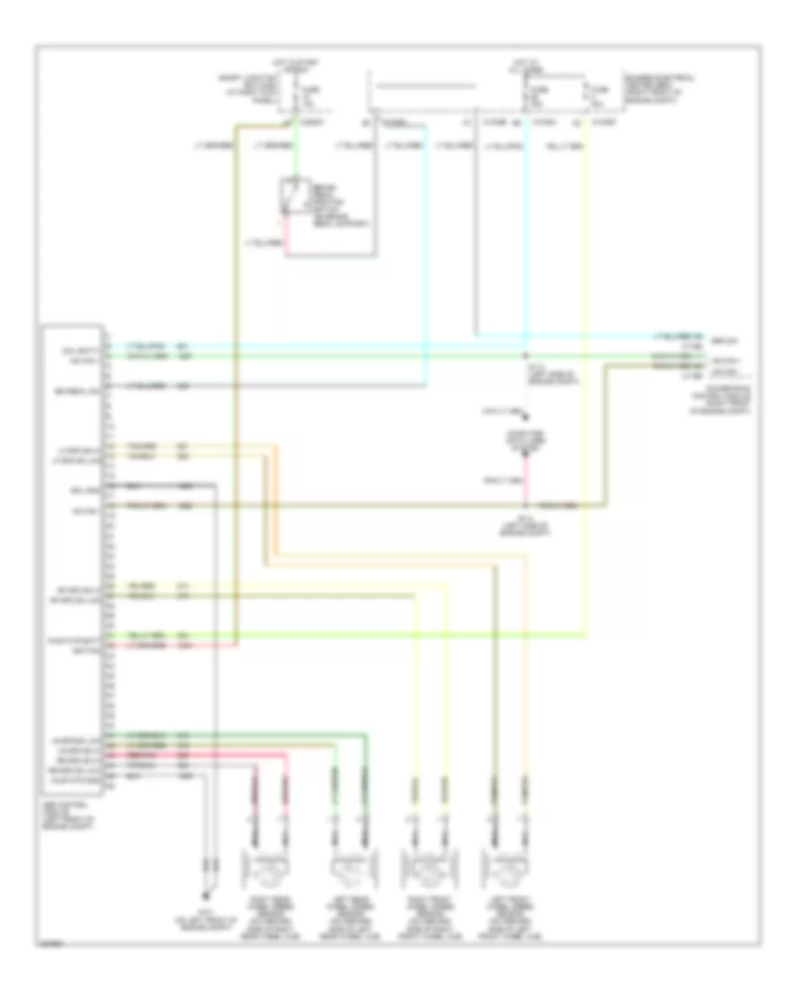
ANTI-LOCK BRAKES Anti-lock Brakes Wiring Diagram for Ford Mustang GT 2006 List of elements for Anti-lock Brakes Wiring Diagram for Ford Mustang GT 2006: 43 Abs control module (left front of engine compt) Br pedal sw Brake pedal position switch (on brake pedal support) Brk sw Bussed electrical center (bec) (right front of engine compt) C1035a C1035b C1035d C175b C175e C2280h Coil batt+ Computer data lines system Ecu gnd Fuse 10a Fuse 30a Fuse 40a G101 (on left front of engine compt) Hot at all times Hot in start or run Hs can + Hs can - Ignition Left front wheel speed sensor (on inboard side of left front wheel hub) Left rear wheel speed sensor (on inboard side of left rear wheel hub) Lf spd sn hi Lf spd sn low Lr spd sn hi Lr spd sn low Nca Powertrain control module (right front of engine compt) Pump mtr batt Pump mtr gnd Red/pnk Rf spd sn hi Rf spd sn low Right front wheel speed sensor (on inboard side of right front wheel hub) Right rear wheel speed sensor (on inboard side of right rear wheel hub) Rr spd sn hi Rr spd sn low S113 (left side of engine compt) S114 (left side of engine compt) Smart junction box (sjb) (at right kick panel)
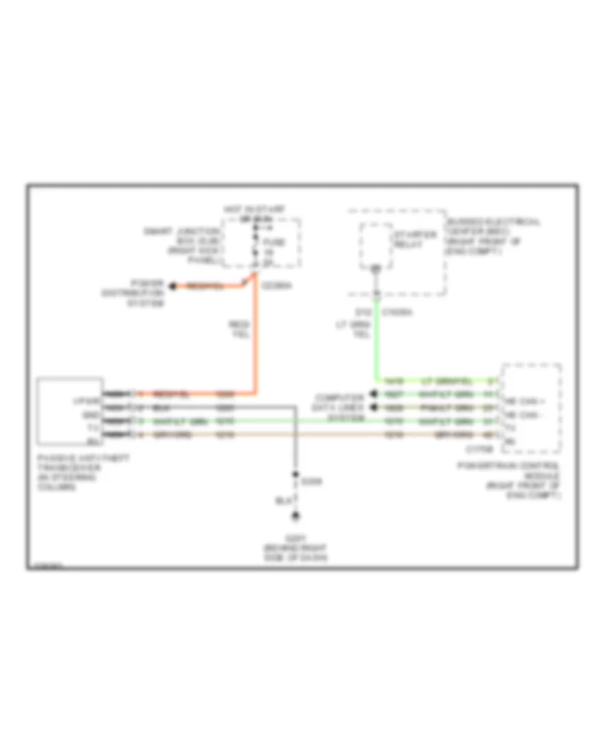
ANTI-THEFT Forced Entry Wiring Diagram (1 of 2) for Ford Mustang GT 2006 List of elements for Forced Entry Wiring Diagram (1 of 2) for Ford Mustang GT 2006: 46 Bussed electrical center (bec) (right front of engine compartment) C2280a C2280c C2280d C2280e C2280f C2280g C2280h D9 c1035a Disarm sw Door lock relay Door unlock relay Driver door unlock relay Driver side door lock switch Fuse 20a Fuse 5a G201 (behind right side of dash) G203 (at right "a" pillar) G204 (at right "a" pillar) Horn output Hot at all times Inhibit sw disarm Inhibit sw set Interior lights system Intrusion sens Left front door ajar switch (rear of left front door) Left front door lock actuator (rear of left front door) Lock Low current board Passenger side door lock switch Red Right front door ajar switch (rear of right front door) Right front door lock actuator (rear of right front door) S201 S203 (at left kick panel) S215 S222 S503 S604 (right window regulator harness) Smart junction box (sjb) (at right kick panel) Sw lock sig Sw sens Sw sig Sw unlock sig Tan Un- lock Forced Entry Wiring Diagram (2 of 2) for Ford Mustang GT 2006 List of elements for Forced Entry Wiring Diagram (2 of 2) for Ford Mustang GT 2006: 24 Anti-theft hood switch (right front of engine compt) Anti-theft horn (right side of luggage compt) Anti-theft inhibit switch (rear of driver's door) Anti-theft luggage compartment switch (center of luggage compt lid) Arm Bussed electrical center (bec) (right front of eng compt) C1035c D11 Dis- arm E11 c1035c G100 (right side of radiator support) G204 (at left kick panel) G402 (right rear of luggage compt) Gnd Ground distribution system Intrusion sense Luggage compartment lid ajar switch (center of luggage compt lid) Overhead console S112 S215 S406 S503 Tan Vbatt Passive Anti-theft Wiring Diagram for Ford Mustang GT 2006 List of elements for Passive Anti-theft Wiring Diagram for Ford Mustang GT 2006: 17 Bussed electrical center (bec) (right front of eng compt) C175b C2280a Computer data lines system D12 c1035a Fuse 5a G201 (behind right side of dash) Hot in start or run Hs can + Hs can - Nca vpwr nca gnd nca tx nca rx Passive anti-theft transceiver (in steering column) Power distribution system Powertrain control module (right front of eng compt) S209 Smart junction box (sjb) (right kick panel) Starter relay
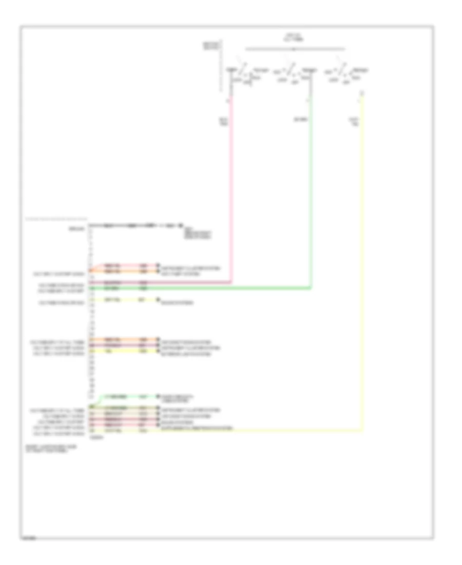
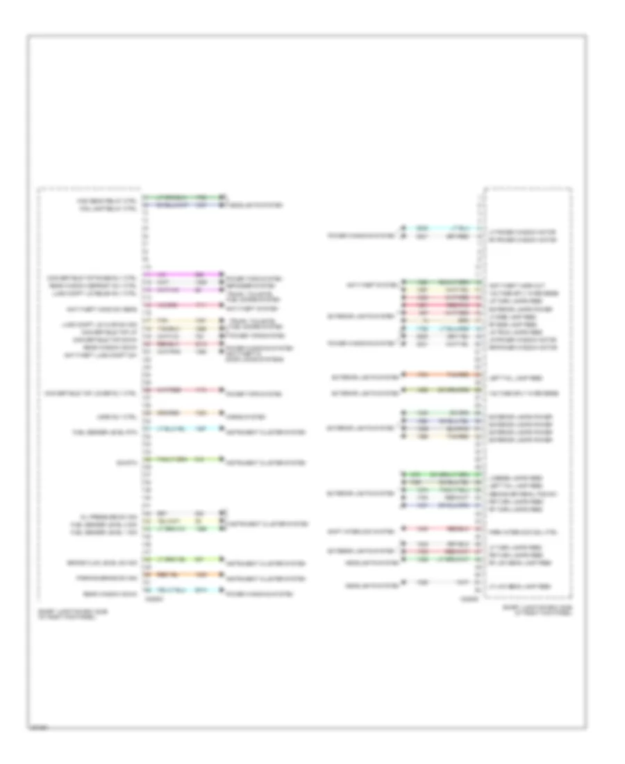
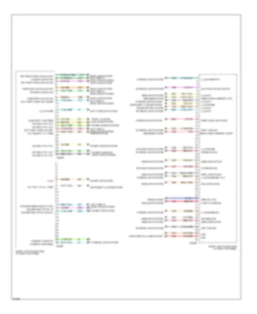
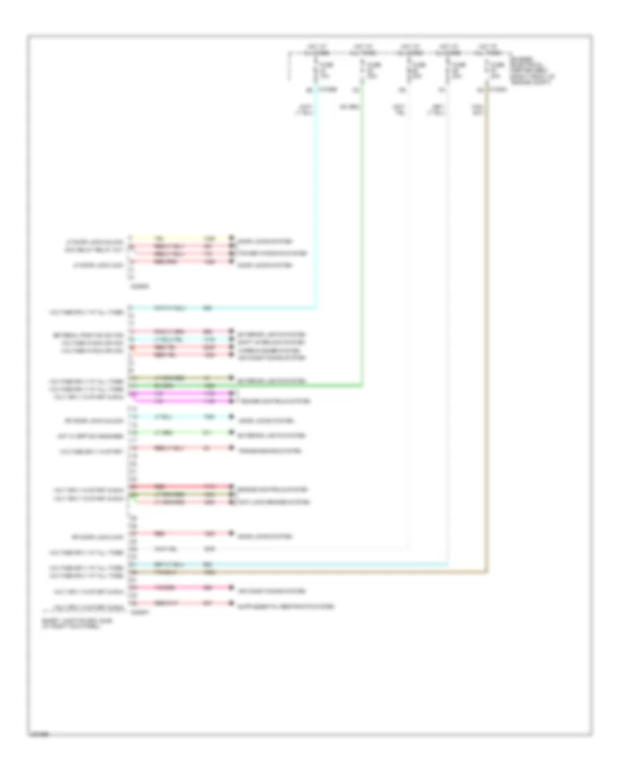
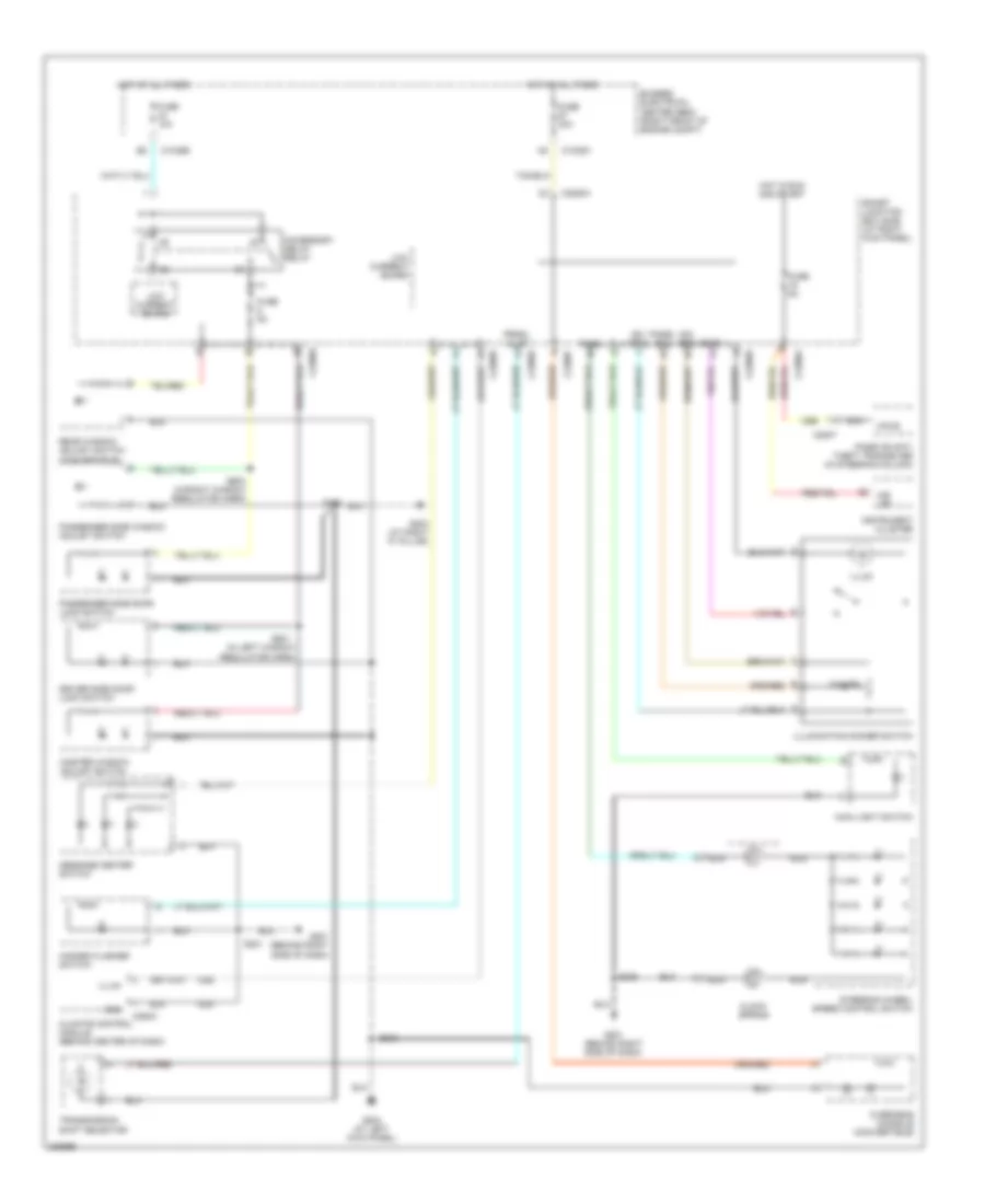
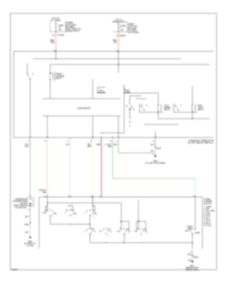
BODY CONTROL MODULES Body Control Modules Wiring Diagram (1 of 4) for Ford Mustang GT 2006 List of elements for Body Control Modules Wiring Diagram (1 of 4) for Ford Mustang GT 2006: 23 Acc Air conditioning system Anti-theft system C2280a Computer data lines system Exterior lights system G201 (behind right side of dash) Ground Hot at all times Ignition switch Instrument cluster system Lock Off Run S201 Smart junction box (sjb) (at right kick panel) Sound systems Start Volt sply in start & run Voltage in run or acc Voltage sply at all times Voltage sply in run Voltage sply in start Body Control Modules Wiring Diagram (2 of 4) for Ford Mustang GT 2006 List of elements for Body Control Modules Wiring Diagram (2 of 4) for Ford Mustang GT 2006: 57 Anti-theft hood sw sens Anti-theft horn out Anti-theft lugg compt sw Anti-theft system Brake fluid level sw sig C2280c C2280d Convertible top down Convertible top lower rly ctrl Convertible top raise rly ctrl Convertible top up Defogger system Exterior lamps power Exterior lights system Fog lamp relay ctrl Fuel sender level 1 sig Fuel sender level 2 sig Fuel sender level rtn Headlights system High beam relay ctrl Horn rly ctrl Horns system Instrument cluster system Left tail lamp feed Lf low beam lamp feed Lf power window motor Lf side lamp feed Lf turn lamps feed License lamps feed Lr power window motor Lr trun lamps feed Lr turn lamps feed Lugg compt lid ajar sw sig Lugg compt lid relea rly ctrl Oil pressure sw sig Park interlock sol ctrl Parking brake sw sig Power tops system Power windows system Power windows system anti-theft & door locks systems Rear window defrost rly ctrl Rear window down Red/pnk Rf low beam lamp feed Rf power window motor Rf side lamp feed Rf turn lamps feed Rr power window motor Rr turn lamps feed Second br pedal pos sw Shift interlock system Sig rtn Smart junction box (sjb) (at right kick panel) Tan Tan/red Trunk, tailgate, fuel doors system Voltage sply in reverse Body Control Modules Wiring Diagram (3 of 4) for Ford Mustang GT 2006 List of elements for Body Control Modules Wiring Diagram (3 of 4) for Ford Mustang GT 2006: 64 A/c demand sig Acc delay rly out Air conditioning system Anti-theft & door locks systems Anti-theft & door locks systems mirrors system Anti-theft inhibit sw disarm Anti-theft inhibit sw set C2280b C2280e C2280f Can+ Can- Computer data lines system Convertible top sw down 3 Convertible top sw up Cruise control system Defogger system Door locks system Door locks system anti-theft & door locks systems Drv front door lock sw sig Drv front door lock/unlock Exterior lights system Flash to pass sig Fog lamps on sig Front dome lamp on sig Hazard sw sig Headlamps off sig Headlamps on sig Headlights system High beam sig Horn sw ctrl Horns system Illum Illum dimmer ref volt Illum dimmer rtn Illum dimmer sig Illum out Illum power Instrument cluster system Interior lamps feed Interior lamps rtn Interior lights system Intrusion sens module tx/rx Left turn sig Lf door ajar sw sig Lugg compt lamp feed Multifunction sw sig rtn Park lamps on sig Pass door lock sw sig Pass door lock/unlock sw Pnk Power tops system Power windows & door locks systems Power windows system Rear window defrost ctrl Rear window defrost on/off Red/pnk Rf door ajar sw sig Right turn sig Shift interlock system Smart junction box (sjb) (at right kick panel) Trunk, tailgate, fuel doors system Volt sply at all times Voltage sply at times Body Control Modules Wiring Diagram (4 of 4) for Ford Mustang GT 2006 List of elements for Body Control Modules Wiring Diagram (4 of 4) for Ford Mustang GT 2006: 31 Acc delay relay out Air conditioning system Anti-lock brakes system Br pedal position sw sig Bussed electrical center (bec) (right front of engine compt) C1035a a5 C1035b b2 C2280g C2280h Door locks system Engine controls system Exterior lights system Fuse 10a Fuse 20a Fuse 30a Hot at all times Hot w/ bpp sw engaged Lf door lock/lock Lf door lock/unlock Power windows system Red Rf door lock/lock Rf door lock/unlock Shift interlock system Smart junction box (sjb) (at right kick panel) Transmissions system Volt sply in start & run Voltage in run or acc Voltage sply at all times Voltage sply in start Wiper/washer system
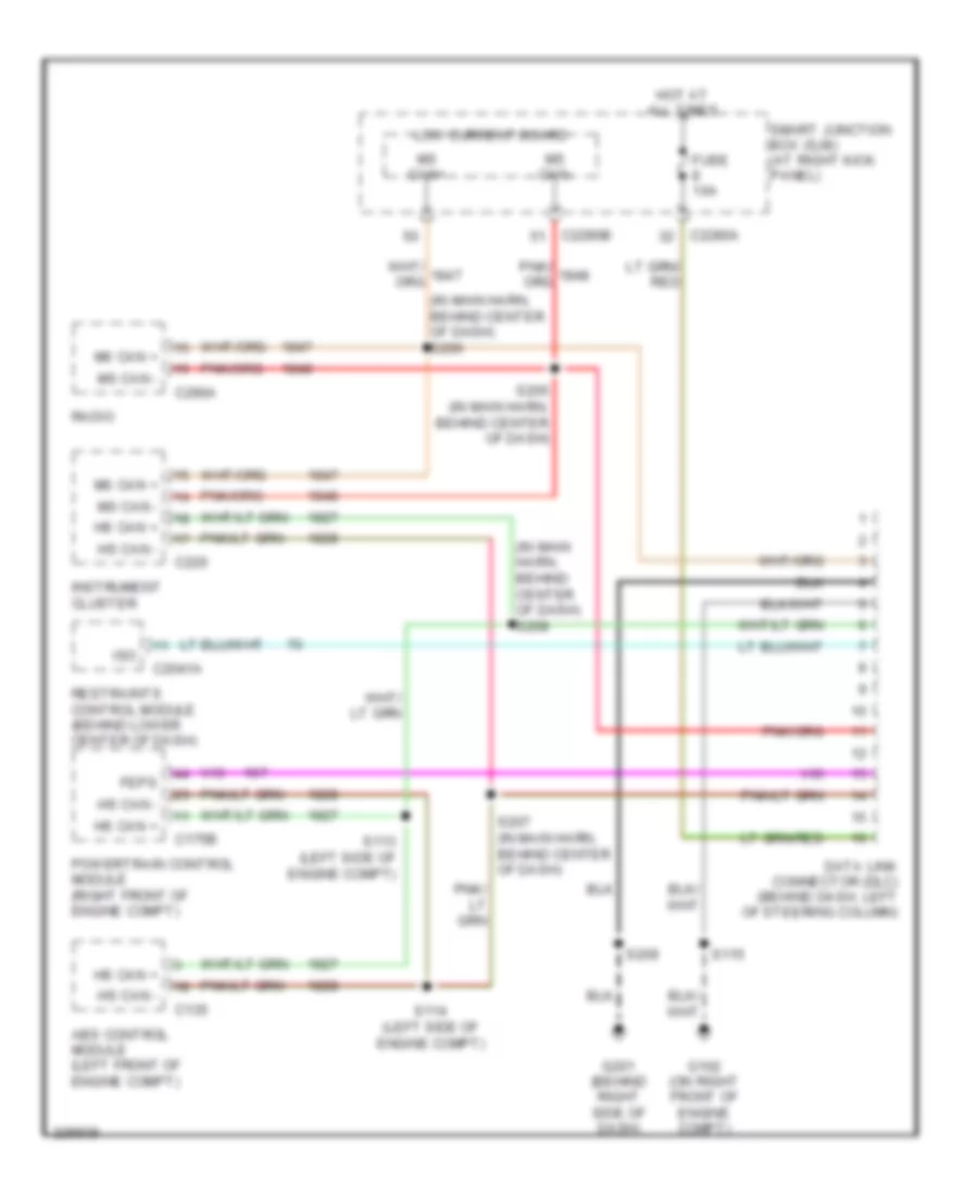
COMPUTER DATA LINES Computer Data Lines Wiring Diagram for Ford Mustang GT 2006 List of elements for Computer Data Lines Wiring Diagram for Ford Mustang GT 2006: 35 (in main harn, behind center of dash) s206 (in main harn, behind center of dash) s208 Abs control module (left front of engine compt) C135 C175b C2041a C220 C2280a C2280b C290a Data link connector (dlc) (behind dash, left of steering column) Feps Fuse 10a G102 (on right front of engine compt) G201 (behind right side of dash) Hot at all times Hs can + Hs can - Instrument cluster Iso Low current board Ms can + Ms can - Ms can+ Ms can- Powertrain control module (right front of engine compt) Radio Restraints control module (behind lower center of dash) S113 (left side of engine compt) S114 (left side of engine compt) S115 S205 (in main harn, behind center of dash) S207 (in main harn, behind center of dash) S209 Smart junction box (sjb) (at right kick panel)
COOLING FAN
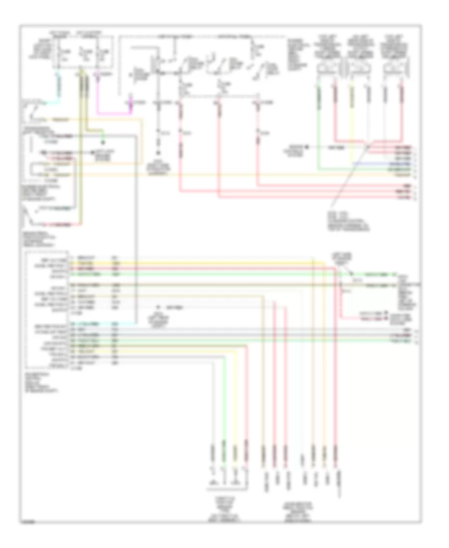
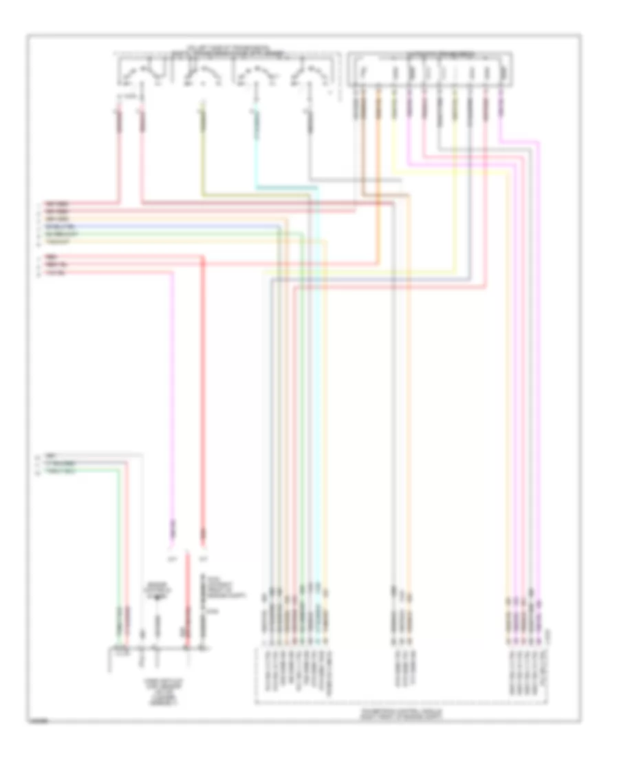
4.0L 4.0L, Cooling Fan Wiring Diagram for Ford Mustang GT 2006 List of elements for 4.0L, Cooling Fan Wiring Diagram for Ford Mustang GT 2006: 31 (in engine control sensor harn, on top of engine) (in engine control sensor harness, near breakout to egr system module) A/c pressure transducer sensor (left front of engine compt) A12 Bussed electrical center (bec) (right front of engine compartment) C1035b C1035c C11 C12 C175b C175e Ect sig Engine coolant temperature sensor (on top front of engine) Engine cooling fan motor (right front of engine compt) F12 Fuse 15a Fuse 40a G100 (right side of radiator support) High speed engine cooling fan relay Hot at all times Hot in start or run Low speed engine cooling fan relay Powertrain control module (pcm) (right front of engine compt) Ref volt Rly ctrl S102 S103 S116 (right front of engine compt) Sig ret Sw sig Tan/red
4.6L 4.6L, Cooling Fan Wiring Diagram for Ford Mustang GT 2006 List of elements for 4.6L, Cooling Fan Wiring Diagram for Ford Mustang GT 2006: 34 (in engine control sensor harness, at rear of engine) A/c clutch cycling pressure switch (left rear corner of engine compt) A12 Bussed electrical center (bec) (right front of engine compartment) C1035b C1035c C11 C12 C175b C175e C2280h Cylinder head temperature sensor (right rear of engine) Dual pressure switch (left front of engine compt) Engine cooling fan motor (right front of engine compt) F12 Fuse 15a Fuse 40a Fuse 5a G100 (right side of radiator support) G203 (at right "a" pillar) High speed engine cooling fan relay Hot at all times Hot in start or run Low speed engine cooling fan relay Powertrain control module (pcm) (right front of engine compt) Rly ctrl S100 S106 S116 (right front of engine compt) Sensor sig Sig ret Smart junction box (sjb) (at right kick panel) Sw sig Tan/red
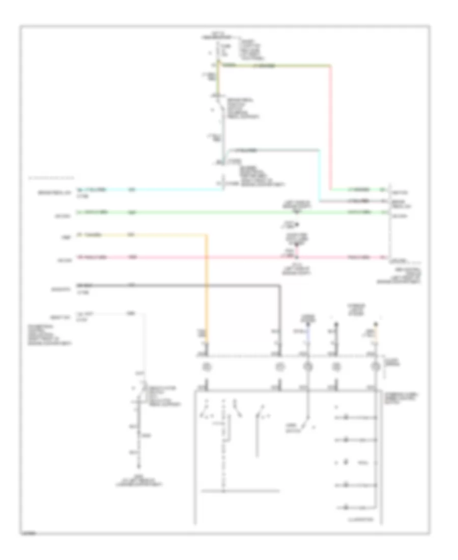
CRUISE CONTROL Cruise Control Wiring Diagram for Ford Mustang GT 2006 List of elements for Cruise Control Wiring Diagram for Ford Mustang GT 2006: 34 (left side of engine compt) s113 Abs control module (left front of engine compartment) Brake pedal position switch (on brake pedal support) Brake pedal sw Bussed electrical center (bec) (right front of engine compartment) C1035a C1035b C175b C175e C175t C2280h Clock spring Computer data lines system Deact sw Deactivator switch (m/t) (on clutch pedal support) Fuse 10a G400 (at left rear of luggage compartment) Horn Horns system Hot in run or start Hs can+ Hs can- Ignition Illumination Interior lights system Nca Powertrain control module (pcm) (right front of engine compartment) S114 (left side of engine compt) S408 Sccs rtn Smart junction box (sjb) (at right kick panel) Steering wheel/ speed control switch Switch Vref
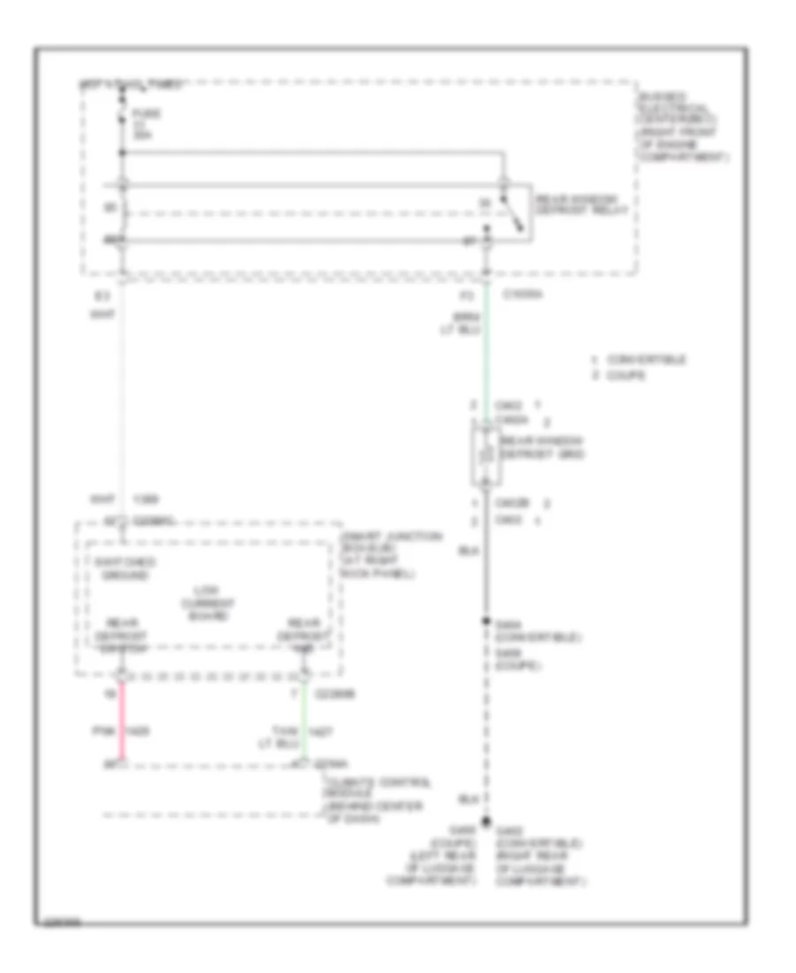
DEFOGGERS Defoggers Wiring Diagram for Ford Mustang GT 2006 List of elements for Defoggers Wiring Diagram for Ford Mustang GT 2006: 26 Bussed electrical center(bec) (right front of engine compartment) C1035a C2280b C2280c C294a C402 C402a C402b Climate control module (behind center of dash) Convertible Coupe Fuse 30a G400 (coupe) (left rear of luggage compartment) G402 (convertible) (right rear of luggage compartment) Hot at all times Low current board Pnk Rear defrost ind Rear defrost switch Rear window defrost grid Rear window defrost relay S404 (convertible) S408 (coupe) Smart junction box(sjb) (at right kick panel) Switched ground Tan/
ENGINE PERFORMANCE
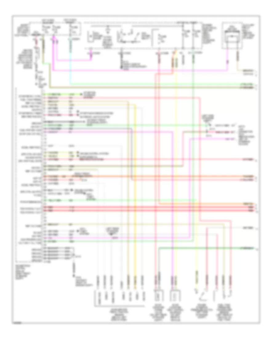
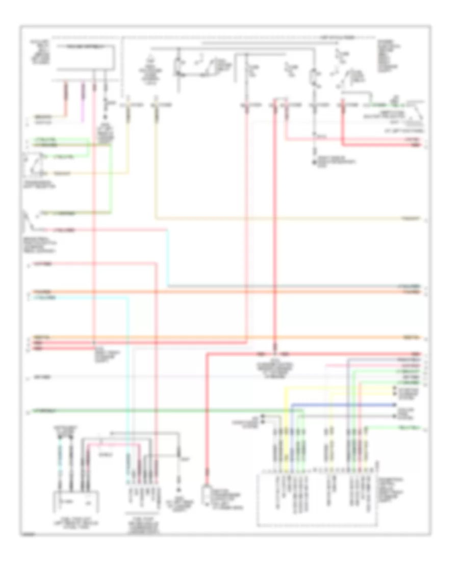
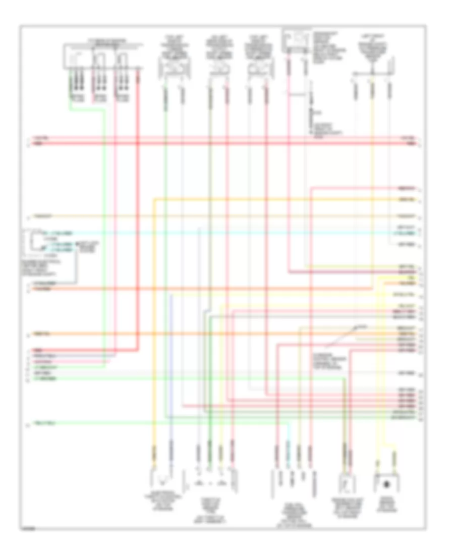
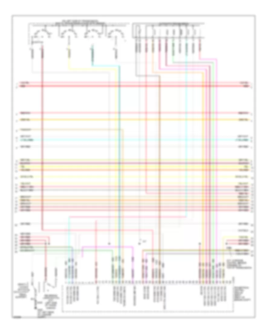
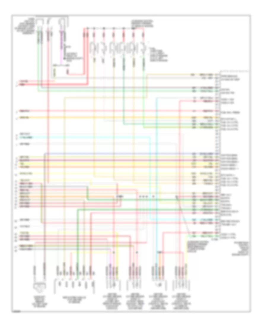
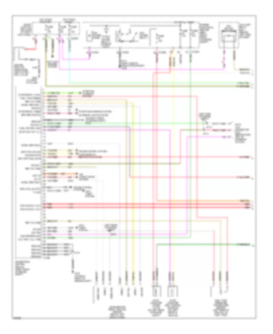
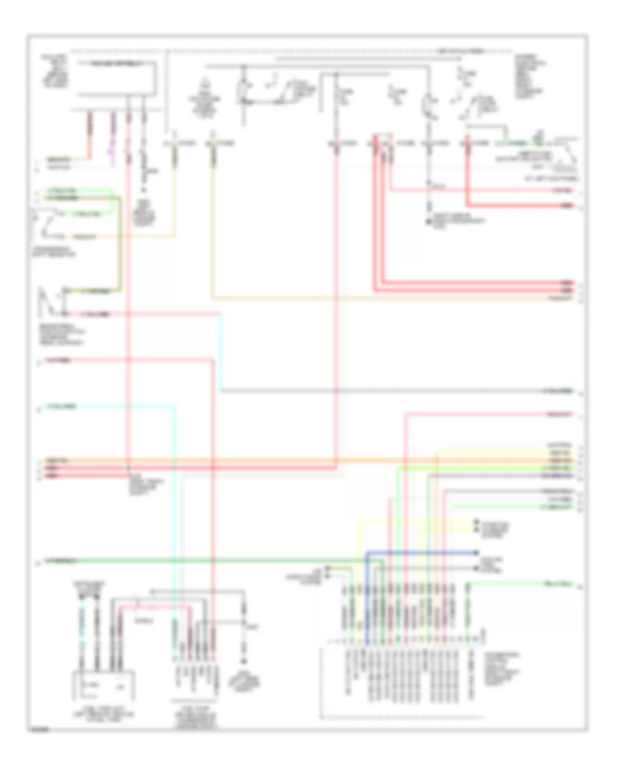
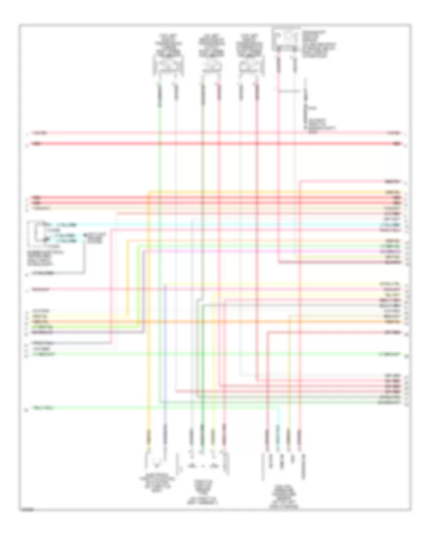
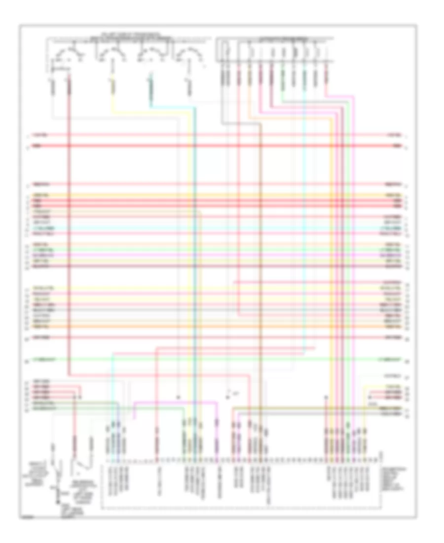
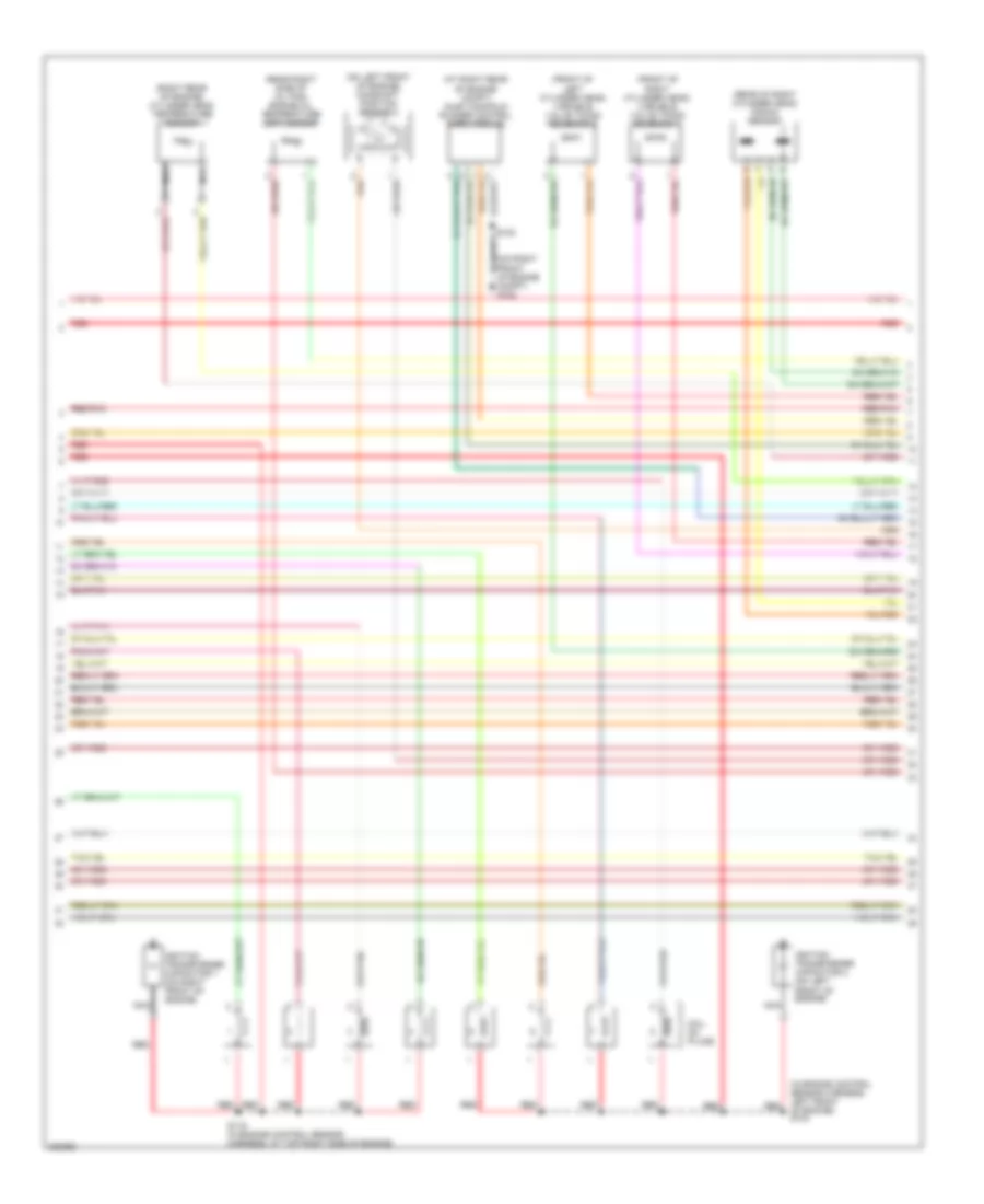
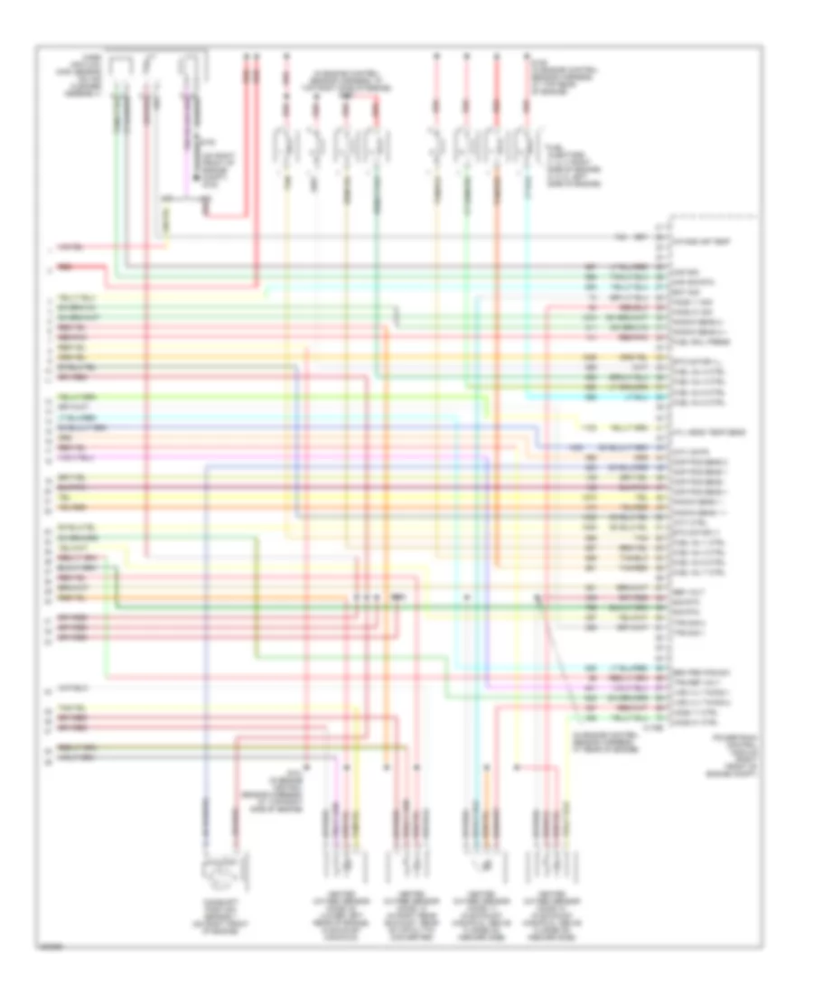
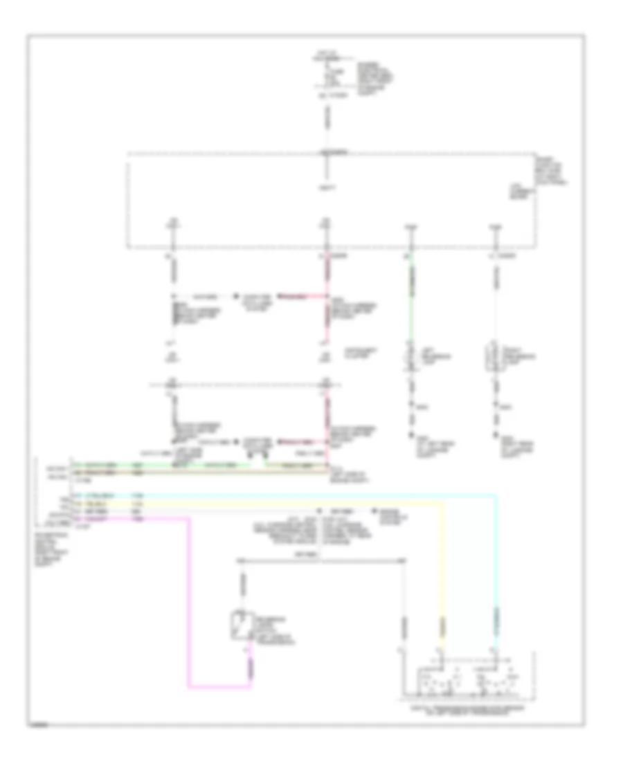
4.0L 4.0L, Engine Performance Wiring Diagram (1 of 5) for Ford Mustang GT 2006 List of elements for 4.0L, Engine Performance Wiring Diagram (1 of 5) for Ford Mustang GT 2006: 77 (at right "a" pillar) g203 (left rear of engine compt) (left side of engine compt) (on right front of engine compt) g103 (right front of engine compt) 57o Accel ped pos 1 Accel ped pos 2 Accel ped pos 3 Accelerator pedal position sensor (below left side of dash) Acp v6 Acp v8 Aid bag mntr Anti- theft system Auxiliary relay box 1 (behind left side of dash) Brk ped pos sw Bussed electrical center (bec) (right front of engine compt) C175b Cruise control system Data link connector (dlc) (behind dash, left of steering column) Drv pmp fuel mntr Evap can vnt sol Evap canister purge valve (on left rear of engine compt) Evap canister vent control solenoid (on left rear of vehicle) Exterior lights system Fuel pmp drv mod Fuel tank press Fuel tank pressure transducer sensor (left rear of vehicle, on fuel tank) Fuse 10a Fuse 15a Fuse 5a G102 (on right front of engine compt) Ground Heated positive crankcase ventilation (pcv) valve (on top right side of engine) Hot at all times Hot in run or acc Hot in run or start Hs can + Hs can - Mod program sig Pcm key-off relay diode Pcm power diode Pcm power relay 1 Pcm pwr rly out Pcv heater Power steering pressure switch (left side of engine compt) Powertrain control module (right front of engine compt) Pwr steering sw Red Red/pnk Ref vol Ref voltage Rx sig S100 S113 S114 S115 S116 S212 Sens 1 Sens 2 Sens 3 Sens rtn Sens vref Sig rtn Sig trn Smart junction box (sjb) (at right kick panel) Spd ctrl sw rtn Spd ctrl sw sig Starter rly ctrl Starter rly feed Starting/ charging system Starting/charging system Tan/red To pcm power relay 2 (diagram 2 of 5) Tx sig Volt sply all time 4.0L, Engine Performance Wiring Diagram (2 of 5) for Ford Mustang GT 2006 List of elements for 4.0L, Engine Performance Wiring Diagram (2 of 5) for Ford Mustang GT 2006: 52 (at left kick panel) (right side of radiator support) g100 A/c clt rly ctrl A/c clutch Air conditioning system Auxiliary relay box 1 (behind left side of dash) Bat Brake pedal position switch (on brake pedal support) Bussed electrical center (bec) (right front of engine compt) C1035a b6 red C1035a c12 C1035b f6 red C175e C5 red Cooling fans system Ect sen sig Evap can vnt vlv Fp ctrl Fp monitor Fp power Fp rtn From pcm power diode (diagram 1 of 5) Fuel pump driver module (underside of luggage compt) Fuel pump relay Fuel rail temp sig Fuel tank unit (left rear of vehicle, in fuel tank) Fuse 15a G400 (at left rear of luggage compt) Gen com Gnd Hi spd eng fan rly Hot at all times Ign coil 1/cop 1 Ign coil 2/cop 7 Ign coil 3/cop 3 Ignition transformer capacitor (on left cylinder head) Inertia fuel shutoff (ifs) switch Instrument cluster system Lo spd eng fan rly Nca Pcm key-off relay Pcm power relay Powertrain control module (right front of engine compt) Red S104 (in engine control sensor harness, at top rear of engine) S112 S120 (right front of engine compt) S407 Shield Starting/ charging system Tan/red Transmission shift selector 4.0L, Engine Performance Wiring Diagram (3 of 5) for Ford Mustang GT 2006 List of elements for 4.0L, Engine Performance Wiring Diagram (3 of 5) for Ford Mustang GT 2006: 29 (in engine control sensor harness, 0n top of engine) (left front of engine compt) a/c pressure transducer sensor (on left rear side of transmission) output shaft speed (oss) sensor (on right front of engine compt) g102 (on throttle body assembly) (on top front of engine) (to rear of engine) ignition coil (top left side of transmission) intermediate shaft speed (iss) sensor (top left side of transmission) turbine shaft speed (tss) sensor Anti-lock brakes system Bussed electrical center (bec) (right front of engine compt) C1035a C1035b Crankshaft position sensor (on center front of engine, below right side of water pump) Electronic throttle control (etc) motor (on top of engine) Engine coolant temperature (ect) sensor Fuel rail pressure transducer sensor (on fuel rail, on top of engine) Knock sensor (on top of engine) Nca Pressure sn Red Red/pnk S103 Sig rtn Spark plugs Tan/red Temp sn Throttle position sensor (tps) Vref 4.0L, Engine Performance Wiring Diagram (4 of 5) for Ford Mustang GT 2006 List of elements for 4.0L, Engine Performance Wiring Diagram (4 of 5) for Ford Mustang GT 2006: 37 (m/t: in engine control sensor harness, on top of transmission) (on left side of transmission) digital transmission range (dtr) sensor A/t Automatic transmission C175t Deacti- vator switch (on clutch pedal support) Dtr sens tr1 Dtr sens tr2 Dtr sens tr3a Dtr sens tr4 G400 (at left rear of luggage compt) Ho2s 12 ctrl Ho2s 12 sig Ho2s 22 ctrl Ho2s 22 sig Iss sens sig Oss sens sig Pca sol a ctrl Pcb sol b ctrl Pcc sol c ctrl Powertrain control module (right front of engine compt) Red Red/pnk Reverse lmp sw Reversing lamps switch (m/t) (left side of trans- mission) S106 S408 Shift sol a ctrl Shift sol b ctrl Shift sol c ctrl Shift sol d ctrl Sig rtn Spd ctrl deact sw Tcc sol ctrl Tft sens sig Trans od cancel Tss sens sig 4.0L, Engine Performance Wiring Diagram (5 of 5) for Ford Mustang GT 2006 List of elements for 4.0L, Engine Performance Wiring Diagram (5 of 5) for Ford Mustang GT 2006: 57 357 (in engine control sensor harness, at rear of engine) s107 (in engine control sensor harness, near breakout to egr system module) (on right front of engine compt) g102 A/t Brk ped pos sw C175e Camshaft position sensor (on left side of engine) Ckp pos sens + Ckp pos sens - Cmp pos sens Dpfe Dpfe sens sig Egr sys mod in Egr system module (top center of engine) Etc mntr +/- Etc motor +/_ Evr ctrl Evr- Fuel inj 1 ctrl Fuel inj 2 ctrl Fuel inj 3 ctrl Fuel inj 4 ctrl Fuel inj 5 ctrl Fuel inj 6 ctrl Fuel injectors (1, 2, 3: right side of engine) (4, 5, 6: left side of engine) Fuel rail press Gnd Heated oxygen sensor (ho2s) 11 (in exhaust manifold, above flange on inboard side) Heated oxygen sensor (ho2s) 12 (in right rear exhaust, rear of catalytic converter) Heated oxygen sensor (ho2s) 21 (in exhaust manifold, above flange on inboard side) Heated oxygen sensor (ho2s) 22 (lower left rear of engine, in exhaust manifold) Ho2s 11 ctrl Ho2s 11 sig Ho2s 21 ctrl Ho2s 21 sig Intake air temp Knock sens 1 + Knock sens 1 - M/t Maf sig Maf sig trn Map Mass air flow (maf) sensor (on right side of engine compt, on air cleaner assembly) Powertrain control module (right front of engine compt) Red Red/pnk Ref volt S101 S102 Sig rtn Tan Tps ref volt Tps sig 1 Tps sig 2 Vpwr Vsupp
4.6L 4.6L, Engine Performance Wiring Diagram (1 of 6) for Ford Mustang GT 2006 List of elements for 4.6L, Engine Performance Wiring Diagram (1 of 6) for Ford Mustang GT 2006: 73 (left rear of engine compt) (left side of engine compt) (on right front of engine compt) g103 57o Ac v8 Accel ped pos 1 Accel ped pos 2 Accel ped pos 3 Accelerator pedal position sensor (below left side of dash) Acp v6 Aid bag mntr Air conditioning system Anti- theft system Anti-lock brakes system Auxiliary relay box 1 (behind left side of dash) Brk ped pos sw Bussed electrical center (bec) (right front of engine compt) C175b Cruise control system Data link connector (dlc) (behind dash, left of steering column) Drv pmp fuel mntr Evap can vnt vlv Evap canister purge valve (on left rear of engine compt) Evap canister vent control solenoid (on left rear of vehicle) Exterior lights system Fuel pmp drv mod Fuel tank press Fuel tank pressure transducer sensor (left rear of vehicle, on fuel tank) Fuse 10a Fuse 15a Fuse 5a G102 (on right front of engine compt) G203 (at right "a" pillar) Ground Heated positive crankcase ventilation (pcv) valve Hot at all times Hot in run or acc Hot in run or start Hs can + Hs can - Mod program sig Pcm key-off relay diode Pcm power diode Pcm power relay 1 Pcm pwr rly out Powertrain control module (right front of engine compt) Red Red/pnk Ref vol Ref voltage Rx sig S113 S114 S115 S212 Sens 1 Sens 2 Sens 3 Sens rtn Sens vref Sig rtn Sig trn Smart junction box (sjb) (at right kick panel) Spd ctrl sw rtn Spd ctrl sw sig Starter rly ctrl Starter rly feed Starting/ charging system Starting/charging system Tan/red To pcm power relay 2 (diagram 2 of 5) Tx sig Volt sply all time 4.6L, Engine Performance Wiring Diagram (2 of 6) for Ford Mustang GT 2006 List of elements for 4.6L, Engine Performance Wiring Diagram (2 of 6) for Ford Mustang GT 2006: 54 (at left kick panel) (right side of radiator support) g100 A/c clt rly ctrl A/c clutch Air conditioning system Auxiliary relay box 1 (behind left side of dash) Bat Brake pedal position switch (on brake pedal support) Bussed electrical center (bec) (right front of engine compt) C1035a b6 red C1035a c12 C1035b C1035b f6 red C175e C5 red Coil on plug 1 ctrl Coil on plug 2 ctrl Coil on plug 3 ctrl Coil on plug 4 ctrl Coil on plug 5 ctrl Coil on plug 6 ctrl Coil on plug 7 ctrl Coil on plug 8 ctrl Cooling fans system Evap can pur vlv Fp ctrl Fp monitor Fp power Fp rtn From pcm power diode (diagram 1 of 5) Fuel pump driver module (underside of luggage compt) Fuel pump relay Fuel rail temp sig Fuel tank unit (left rear of vehicle, in fuel tank) Fuse 15a G400 (left rear of luggage compt) Gen com Gnd Hi spd eng fan rly Hot at all times Inertia fuel shutoff (ifs) switch Instrument cluster system Lo spd eng fan rly Nca Pcm key-off relay Pcm power relay Powertrain control module (right front of engine compt) Red S112 S120 (right front of engine compt) S407 Shield Starting/ charging system Transmission shift selector 4.6L, Engine Performance Wiring Diagram (3 of 6) for Ford Mustang GT 2006 List of elements for 4.6L, Engine Performance Wiring Diagram (3 of 6) for Ford Mustang GT 2006: 20 (on left rear side of transmission) output shaft speed (oss) sensor (on right front of engine compt) g102 (on throttle body assembly) (top left side of transmission) intermediate shaft speed (iss) sensor (top left side of transmission) turbine shaft speed (tss) sensor Anti-lock brakes system Bussed electrical center (bec) (right front of eng compt) C1035a C1035b Crankshaft position sensor (on center front of engine, below right side of water pump) Electronic throttle control (etc) motor (on throttle body) Fuel rail pressure transducer sensor (on top left side of engine) Nca Pressure sn Red Red/pnk Sig rtn Temp sn Throttle position sensor (tps) Vref 4.6L, Engine Performance Wiring Diagram (4 of 6) for Ford Mustang GT 2006 List of elements for 4.6L, Engine Performance Wiring Diagram (4 of 6) for Ford Mustang GT 2006: 35 (on left side of transmission) digital transmission range (dtr) sensor A/t Automatic transmission C175t Deacti- vator switch (on clutch pedal support) Dtr sens tr2 Dtr sens tr3a Dtr sens tr4 G400 (left rear of luggage compt) Ho2s 12 ctrl Ho2s 12 sig Ho2s 22 ctrl Ho2s 22 sig Iss sens sig Oss sens sig Pca sol a crtl Pcb sol b crtl Pcc sol c ctrl Powertrain control module (right front of eng compt) Red Red/pnk Reverse lmp sw Reversing lamps switch (m/t) (left side of trans- mission) S102 S408 Shift sol a ctrl Shift sol b ctrl Shift sol c ctrl Shift sol d ctrl Sig rtn Spd ctrl deact sw Tcc sol ctrl Tft sens sig Trans od cancel Tss sens sig 4.6L, Engine Performance Wiring Diagram (5 of 6) for Ford Mustang GT 2006 List of elements for 4.6L, Engine Performance Wiring Diagram (5 of 6) for Ford Mustang GT 2006: 16 (at right rear of engine compt) inlet manifold runner control (imrc) module (front of left cylinder head) variable valve timing solenoid 2 (front of right cylinder head) variable valve timing solenoid 1 (in engine control sensor harness, left front of engine) s104 (on left front of engine) camshaft position sensor 2 (on right front of engine compt) g102 (rear of right cylinder head) knock sensor (rear right side of oil pan) engine oil temperature (eot) sensor (right rear of engine) cylinder head temperature sensor Coil on plugs Ignition transformer capacitor 1 (on right front of engine) Ignition transformer capacitor 2 (on left front of engine) Nca Red Red/pnk S119 (in engine control sensor harness, at top right side of engine) 4.6L, Engine Performance Wiring Diagram (6 of 6) for Ford Mustang GT 2006 List of elements for 4.6L, Engine Performance Wiring Diagram (6 of 6) for Ford Mustang GT 2006: 60 357 (in engine control sensor harness, at rear of engine) (in engine control sensor harness, at top right side of engine) s107 (on right front of engine compt) g102 A/t Brk ped pos sw C175e Camshaft position sensor 1 (on right front of engine) Ckp pos sens + Ckp pos sens - Cmp pos sens 1 Cmp pos sens 2 Cyl head temp sens Eot sig Etc motor +/- Etc motor +/_ Fuel inj 1 ctrl Fuel inj 2 ctrl Fuel inj 3 ctrl Fuel inj 4 ctrl Fuel inj 5 ctrl Fuel inj 6 ctrl Fuel inj 7 ctrl Fuel inj 8 ctrl Fuel injectors (1, 2, 3: right side of engine) (4, 5, 6: left side of engine) Fuel rail press Heated oxygen sensor (ho2s) 11 (in exhaust manifold, above flange on inboard side) Heated oxygen sensor (ho2s) 12 (in right rear exhaust, rear of catalytic converter) Heated oxygen sensor (ho2s) 21 (in exhaust manifold, above flange on inboard side) Heated oxygen sensor (ho2s) 22 (lower left rear of engine, in exhaust manifold) Ho2s 11 ctrl Ho2s 11 sig Ho2s 21 ctrl Ho2s 21 sig Imtv ctrl Imtv mntr Intake air temp Knock sens 1 + Knock sens 1 - Knock sens 2 + Knock sens 2 - M/t Maf sig Maf sig rtn Mass air flow (maf) sensor (on air cleaner assembly) Powertrain control module (right front of engine compt) Red Red/pnk Ref volt S101 (in engine control sensor harness, at top right side of engine) S106 S109 (in engine control sensor harness, at top rear of engine) Sig rtn Tan Tan/red Tps ref volt Tps sig 1 Tps sig 2 Var vlv timing 1 Var vlv timing 2
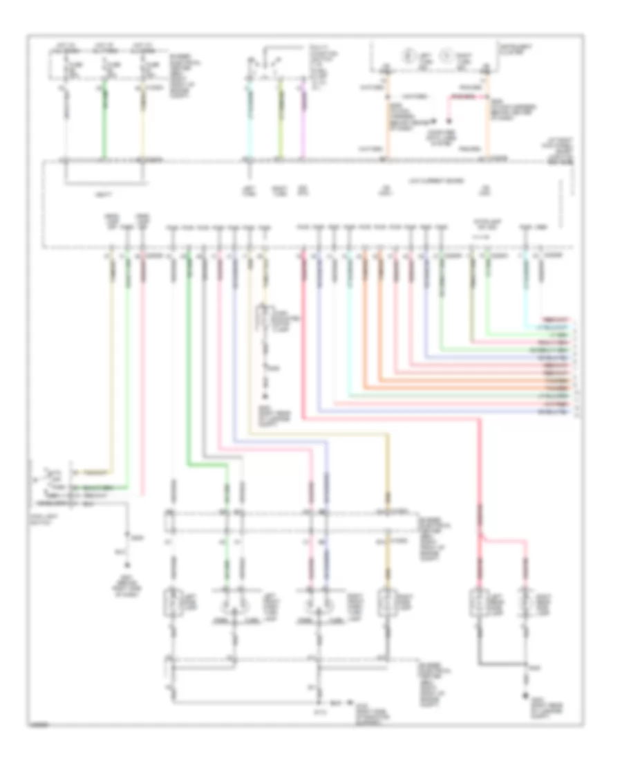
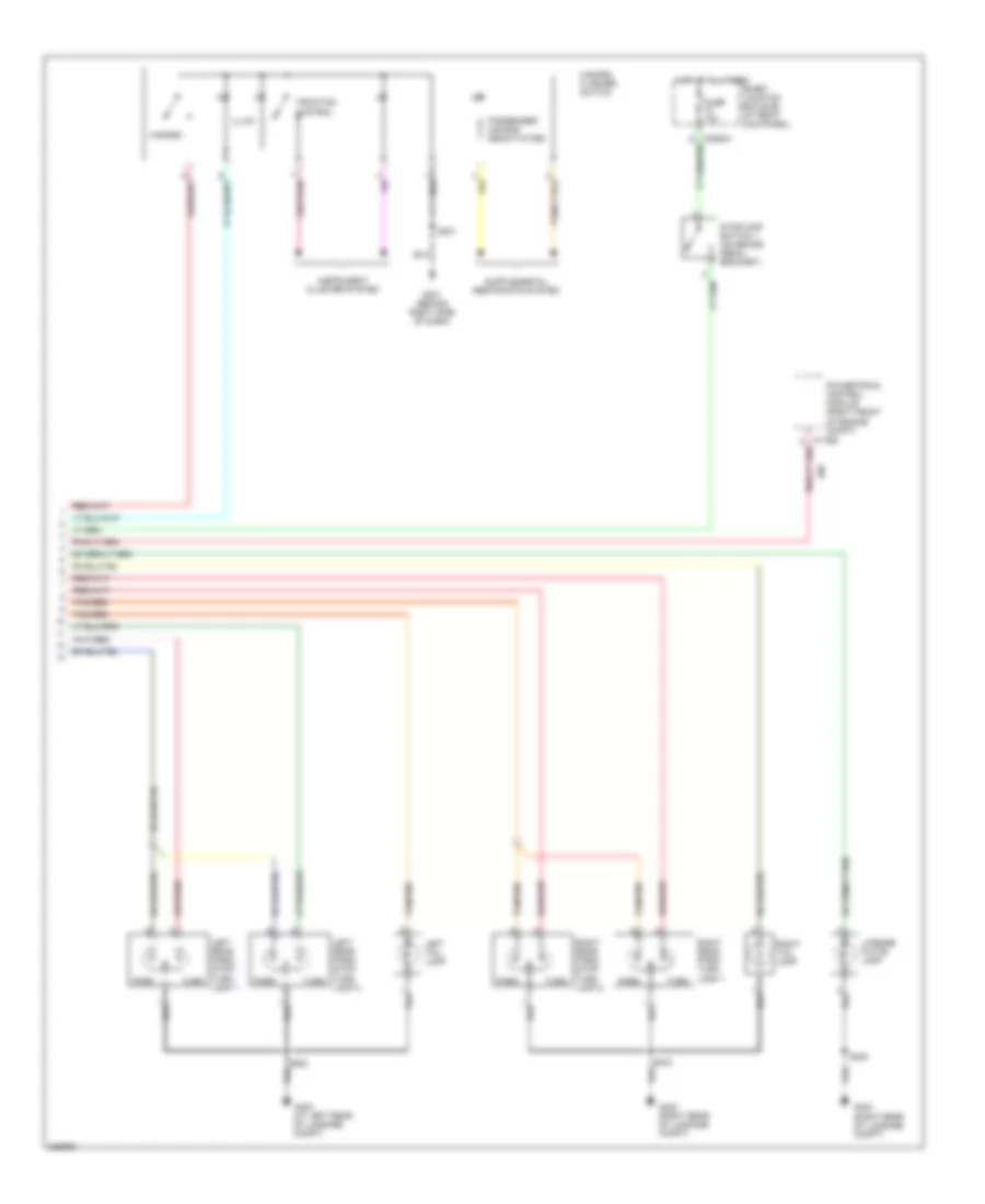
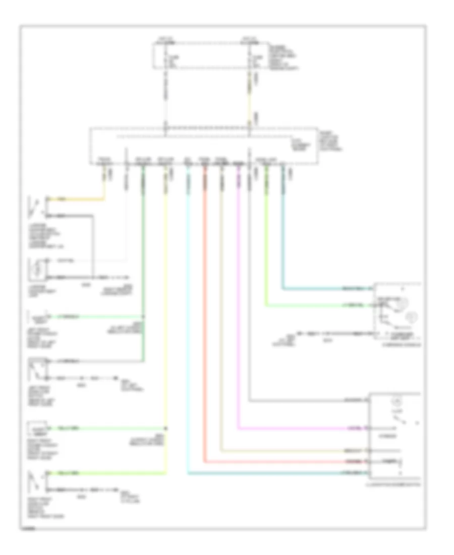
EXTERIOR LIGHTS Back-up Lamps Wiring Diagram for Ford Mustang GT 2006 List of elements for Back-up Lamps Wiring Diagram for Ford Mustang GT 2006: 42 (4.6l: in engine control sensor harness, at rear (a/t) (in main harness, behind center of dash) s207 (in main harness, behind center of dash) s208 (m/t) A/t Behind center of dash) Bussed electrical center (bec) (right front of engine compt) C1035a d9 C175b C175t C2280d C2280h Computer data lines system Digital transmission range (dtr) sensor (on left side of transmission) Engine controls system Fuse 20a G400 (at left rear of luggage compt) G402 (right rear of luggage compt) Hot at all times Hs can + Hs can - Instrument cluster Left reversing lamp Low current board M/t Ms can + Ms can - Powertrain control module (right front of engine compt) Pwr Reversing lamps switch (left side of transmission) Right reversing lamp S106 s102 (4.0l: in engine control sensor harness, near breakout to egr system module) of engine) S114 (left side of engine compt) S402 S403 Sig rtn Smart junction box (sjb) (at right kick panel) Tr1 Tr2 Vbatt Volt ref Exterior Lamps Wiring Diagram (1 of 2) for Ford Mustang GT 2006 List of elements for Exterior Lamps Wiring Diagram (1 of 2) for Ford Mustang GT 2006: 51 (at right kick panel) smart junction box (sjb) Auto Bussed electrical center (bec) (right front of engine compt) C1035a d10 C1035c b10 C2280b C2280h Computer data lines system F10 F11 Fuse 30a G100 (right side of radiator support) G201 (behind right side of dash) G402 (right rear of luggage compt) Head- lamp off Headlamps High mounted stop lamp Hot at all times Instrument cluster Left front park/ turn lamp Left rear side lamp Left side lamp Left turn Left turn sig Low Low current board Main light switch Ms can + Ms can - Multi- function switch 1) r 2) rcl 3) off 4) lcl 5) l Off Park Pwr Red/pnk Right front park/ turn lamp Right rear side lamp Right side lamp Right turn Right turn sig S112 S205 (in main harness, behind center of dash) S206 (in main harness, behind center of dash) S209 S400 S406 Sig rtn Stoplamp sw sig Tan/red Turn Vbatt Vref Exterior Lamps Wiring Diagram (2 of 2) for Ford Mustang GT 2006 List of elements for Exterior Lamps Wiring Diagram (2 of 2) for Ford Mustang GT 2006: 26 Fuse 10a G201 (behind right side of dash) G400 (at left rear of luggage compt) G402 (right rear of luggage compt) Hazard Hazard flasher switch Hot at all times Illum Instrument cluster system Left rear park/ stop/ turn lamp 1 Left rear park/ stop/ turn lamp 2 Left tail lamp License plate lamp Park Passenger air bag deactivated Powertrain control module (right front of engine compt) Right rear park/ stop/ turn lamp 2 Right rear park/ turn lamp 1 Right tail lamp S201 S400 Smart junction box (sjb) (at right kick panel) Stoplamp switch 1 (on brake pedal bracket) Tan/red Traction control Turn
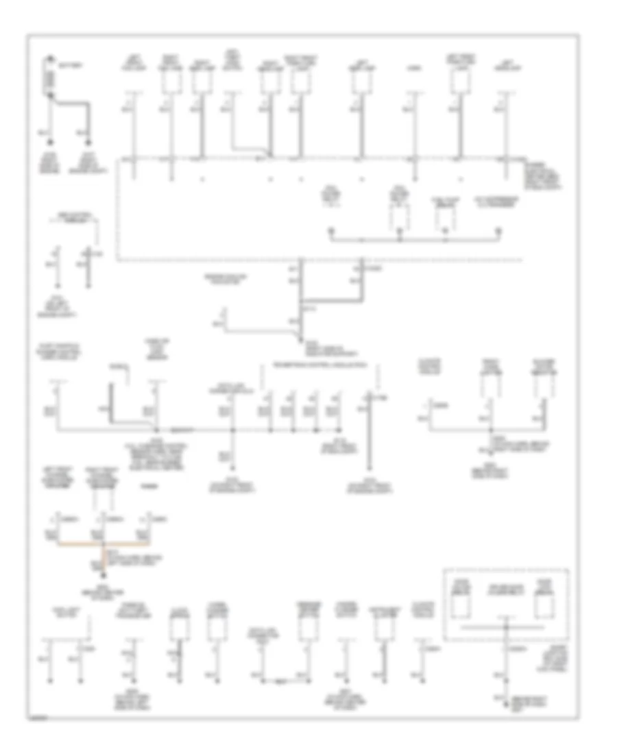
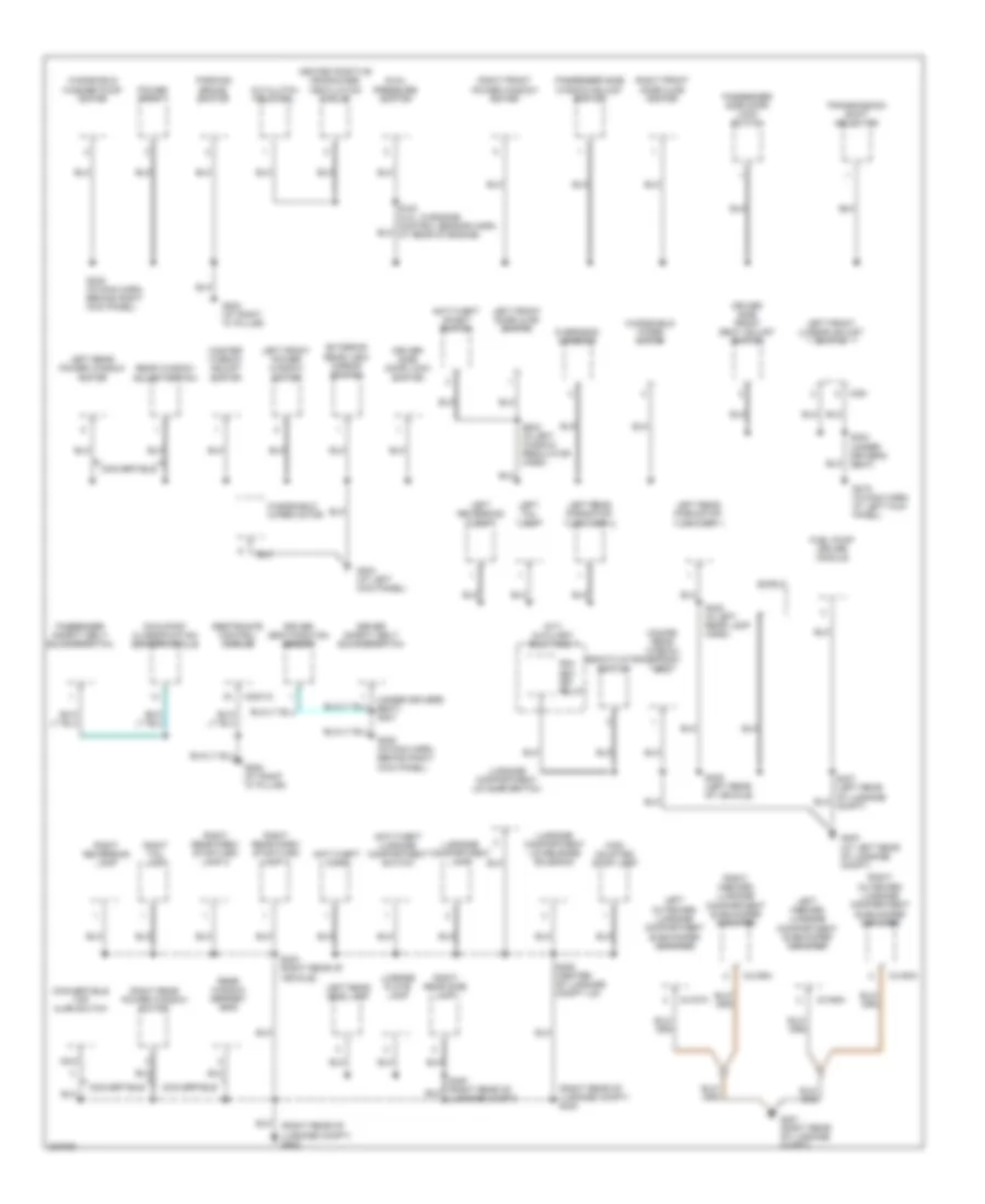
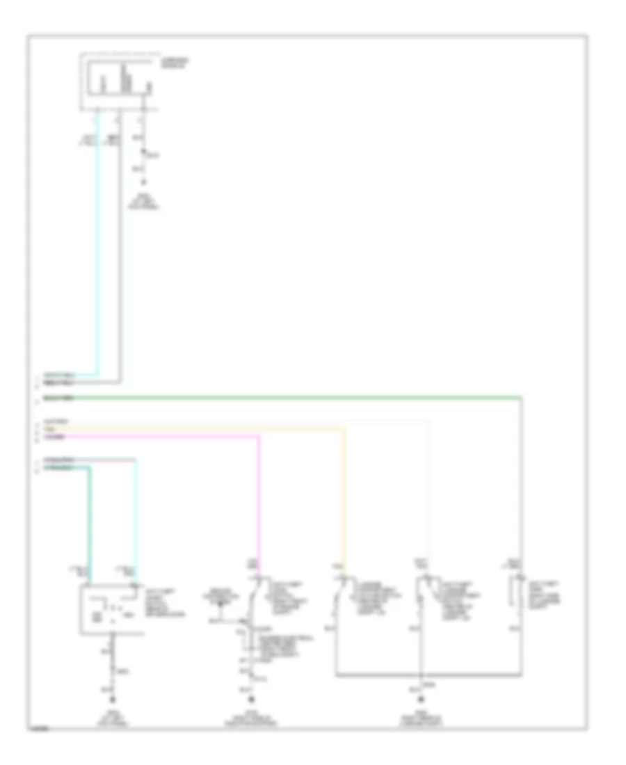
GROUND DISTRIBUTION Ground Distribution Wiring Diagram (1 of 2) for Ford Mustang GT 2006 List of elements for Ground Distribution Wiring Diagram (1 of 2) for Ford Mustang GT 2006: 72 (behind right side of dash) g201 A/c compressor clutch diode Abs control module Anti- theft hood switch Battery Blower motor resistor Bussed electrical center (bec) (right front of eng compt) C1035c d5 C1035c f5 C11 C135 C175b C205 C2280a C290d C294a C294b C2993a C2994a Climate control module Clock spring D11 Data link connector (dlc) Door lock relay Door unlock relay Driver door unlock relay E10 E11 Engine cooling fan motor F10 F11 Front cigar lighter Fuel pump relay G100 (right side of radiator support) G101 (on left front of engine compt) G102 (on right front of engine compt) G103 (on right front of engine compt) G106 (right side of engine) G107 (right side of engine compt) G200 (behind right side of dash) G202 (behind center of dash) Hazard flasher switch Horn Inlet manifold runner control (imrc) module Instrument cluster Left front channel subwoofer amplifier Left front fog lamp Left front park/turn lamp Left headlamp Left side lamp Main light switch Mass air flow (maf) sensor Message center switch Nca Passive anti-theft transceiver Pcm power relay Powertrain control module (pcm) Radio Right front channel subwoofer amplifier Right front fog lamp Right front park/turn lamp Right headlamp Right side lamp S108 (4.0l: in engine control sensor harn, near breakout to c146) (4.6l: near bussed electrical center) S112 S115 (right front of eng compt) S201 (in main harn, behind center of dash) S209 (in main harn, behind left side of dash) S210 (in main harn, behind left side of dash) Shield Smart junction box (sjb) (at right kick panel) Wiper/ washer switch Ground Distribution Wiring Diagram (2 of 2) for Ford Mustang GT 2006 List of elements for Ground Distribution Wiring Diagram (2 of 2) for Ford Mustang GT 2006: 84 (coupe) rear window defrost grid (m/t) auxiliary relay box 1 (right rear of luggage compt) g402 (right rear of luggage compt) s404 (under driver's seat) s301 A/c clutch field coil Anti-theft horn Anti-theft inhibit switch Anti-theft luggage compartment switch C2041a C361 C4157a C4158a C4159a C4160a Convertible Convertible top ajar switch Deactivator switch Driver safety belt buckle switch Driver seat position sensor Driver side door lock switch Driver side front seat adjust switch Dual pressure switch Exterior rear view mirror switch Fuel pump driver module G203 (at right "a" pillar) G204 (at left kick panel) G205 (at right "a" pillar) G400 (at left rear of luggage compt) G401 (right rear of luggage compt) Heated positive crankcase ventilation valve High mounted stop lamp Left front door ajar switch Left front lumbar adjust switch Left front power window motor Left inboard luggage compartment subwoofer amplifier Left outboard luggage compartment subwoofer amplifier Left rear park/stop/ turn lamp 1 Left rear park/stop/ turn lamp 2 Left rear power window motor Left rear side lamp Left reversing lamp Left tail lamp License plate lamp Luggage compartment lamp Luggage compartment lid ajar switch Luggage compartment lid release solenoid Luggage compt) Master window adjust switch Nca Occupant classification sensor module Overhead console Parking brake switch Passenger safety belt buckle switch Passenger side door lock switch Passenger side window adjust switch Pcm key- off relay Power point Rear window adjust switch Rear window defrost grid Restraints control module Right front door ajar switch Right front power window motor Right inboard luggage compartment subwoofer amplifier Right outboard luggage compartment subwoofer amplifier Right rear park/ stop/turn lamp 1 Right rear park/ stop/turn lamp 2 Right rear power window motor Right rear side lamp Right reversing lamp Right tail lamp S215 (in main harn, at left kick panel) S220 (in main harn, behind right kick panel) S222 (in main harn, behind right kick panel) S303 (under driver's seat) S402 (in left rear lamp harn) S403 (right rear of vehicle) S406 (center of luggage compt lid) S408 (left rear of vehicle) S503 (in left window regulator harn) Shield Transmission shift selector Windshield washer pump motor Windshield wiper motor
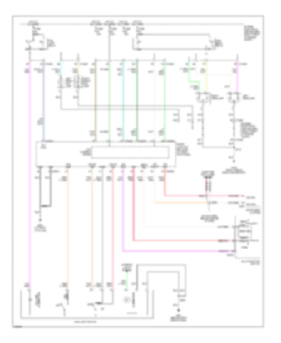
HEADLIGHTS Headlights Wiring Diagram for Ford Mustang GT 2006 List of elements for Headlights Wiring Diagram for Ford Mustang GT 2006: 63 (in main harn, behind center of dash) B11 Beam Beam sel Bussed electrical center (bec) (right front of engine compt) C1035a a3 C1035a f2 C1035c f5 C1035c f6 C11 C202a C220 C2280b C2280c C2280d C2280h Computer data lines system D11 D5 c1035c E10 E11 E7 c1035c Fog lamp Fog lamp illumination Fog lamp relay Ftp Fuse 15a Fuse 30a G100 (right side of radiator support) G201 (behind right side of dash) G203 (at right "a" pillar) Gnd Hdlmp off Hdlmp on High beam relay Hot at all times Illumination Instrument cluster Interior lights system Lamps fog Left front fog lamp Left headlamp Low current board Main light switch Ms can+ Ms can+ip Ms can- Multi-function switch Off Park Pass Red/ pnk Red/pnk Right front fog lamp Right headlamp Rly ctrl S112 S205 S206 S209 S222 Sig rtn Smart junction box (sjb) (at right kick panel)
HORN Horn Wiring Diagram for Ford Mustang GT 2006 List of elements for Horn Wiring Diagram for Ford Mustang GT 2006: 21 25a A1 c1035a Bussed electrical center (bec) (right front of engine compt) C2274 C2280b C2280c Clock spring (below steering wheel) D4 c1035c Fuse G100 (right side of radiator support) G201 (behind right side of dash) Horn Horn (front of radiator) Horn relay Hot at all times Low current board Nca S112 S209 Smart junction box (sjb) (at right kick panel) Steering wheel/speed control switch
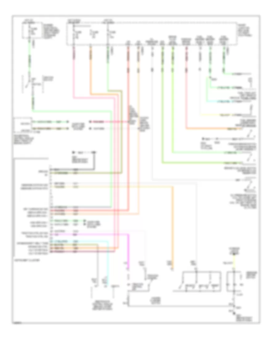
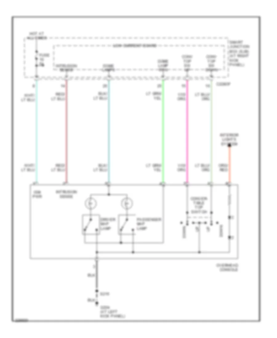
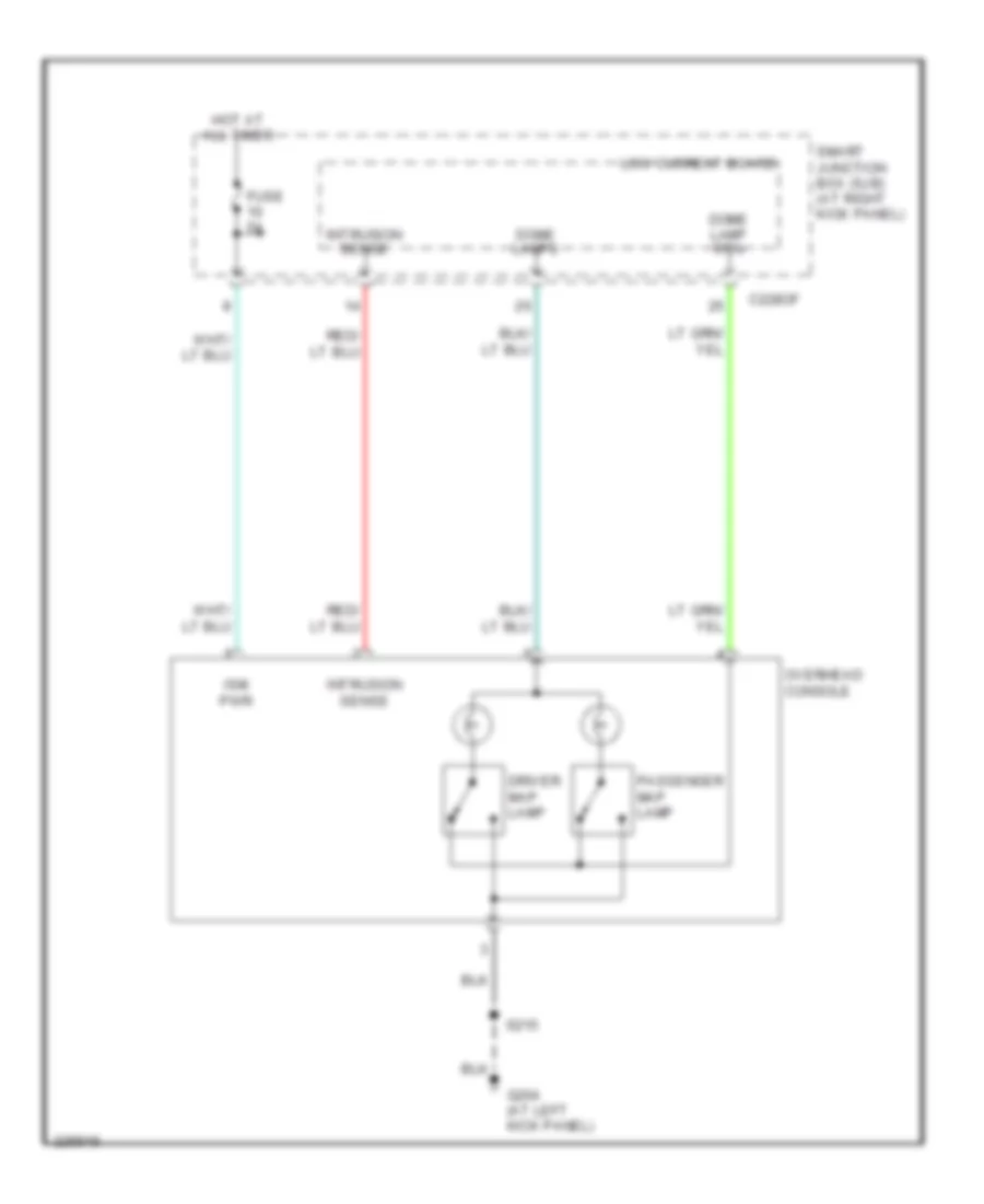
INSTRUMENT CLUSTER Instrument Cluster Wiring Diagram for Ford Mustang GT 2006 List of elements for Instrument Cluster Wiring Diagram for Ford Mustang GT 2006: 65 (in main harn, behind center of dash) s205 (in main harn, behind center of dash) s206 Air bag ind ctrl Air bag/safety belt tone Brake fluid level sw sig Brake fluid level switch (on brake fluid reservoir) Bussed electrical center (bec) (right front of engine compt) C1035a C175b C2041a C228oa C228ob C228oc Computer data lines system Fuel sender (under right rear of vehicle) Fuel sender level 1 sig Fuel sender level 2 sig Fuel sender level rtn Fuel tank unit (left rear of vehicle, in fuel tank) Fuse 10a Fuse 20a Fuse 5a G201 (behind right side of dash) G203 (at right "a" pillar) Ground Hazard flasher switch High spd can + High spd can - Hot at all times Hot in run or start Hs can + Hs can - Ignition switch Illum Instrument cluster Interior lights system Key in ignition Key warning sw sig Medium spd can + Medium spd can - Message center switch Message cntr sw rtn Message cntr sw sig Ms can + Ms can - Nca Oil pressure sw sig Oil pressure switch (4.0l: on lower left front of engine) (4.6l: on left front of engine, near oil filter) Parking brake sw sig Parking brake switch (on parking brake lever assembly) Powertrain control module (right front of engine compt) Reset Restraints control module (behind lower center of dash) S201 S222 S230 Select Set-up Sig rtn Smart junction box (sjb) (at right kick panel) Traction control Traction control off Traction ctrl ind Traction ctrl sw sig Volt start/run Overhead Console Wiring Diagram, Convertible for Ford Mustang GT 2006 List of elements for Overhead Console Wiring Diagram, Convertible for Ford Mustang GT 2006: 20 Box (sjb) (at right kick panel) C228of Conv top sw down Conv top sw up Conver- tible top switch Dome lamp rtn Dome lamps Down Driver map lamp Fuse 5a G204 (at left kick panel) Hot at all times Interior lights system Intrusion sense Ism pwr Low current board Overhead console Passenger map lamp S215 Smart junction Overhead Console Wiring Diagram, Except Convertible for Ford Mustang GT 2006 List of elements for Overhead Console Wiring Diagram, Except Convertible for Ford Mustang GT 2006: 14 C228of Dome lamp rtn Dome lamps Driver map lamp Fuse 5a G204 (at left kick panel) Hot at all times Intrusion sense Ism pwr Low current board Overhead console Passenger map lamp S215 Smart junction box (sjb) (at right kick panel)
INTERIOR LIGHTS Courtesy Lamps Wiring Diagram for Ford Mustang GT 2006 List of elements for Courtesy Lamps Wiring Diagram for Ford Mustang GT 2006: 43 (right front of engine compt) Bussed electrical center (bec) C1035a C2280b C2280c C2280e C2280f C2280h Dimmer Dome Dome lamp rtn Dr ajar switch Driver map light Fuse 30a G203 (at right "a" pillar) G204 (at left kick panel) G402 (right rear of luggage compt) Hot at all times Illum Illumination dimmer switch Interior Left front door ajar switch (rear of left front door) Left front power window motor (front of left front door) Low current board Luggage compartment lamp Luggage compartment lid ajar switch (center of luggage compartment lid) Overhead console Panel dim Panel dim ref Passenger map light Right front door ajar switch (rear of right front door) Right front power window motor (front of right front door) S215 S222 S406 S500 (in left window regulator harn) S503 S604 (in right window regulator harn) Short drop Smart junction box (sjb) (at right kick panel) Sw rtn Tan Trunk ajar sw Instrument Illumination Wiring Diagram for Ford Mustang GT 2006 List of elements for Instrument Illumination Wiring Diagram for Ford Mustang GT 2006: 56 (in left window regulator harn) A/b led Accessory delay relay Bussed electrical center (bec) (right front of engine compt) C1035a C1035b C2007 C2280a C2280b C2280e C2280f C2280h C294a Climate control module (behind center of dash) Clock spring Dim ref Dimmer Dome Driver side door lock switch Fuse 10a Fuse 30a Fuse 5a G201 (behind right side of dash) G203 (at right "a" pillar) G204 (at left kick panel) Gnd Hazard flasher switch Hot at all times Hot in run and start Illum Illumination dimmer switch Instrument cluster Low current board Main light switch Master window adjust switch Message center switch Nca Overhead console (convertible) Panel dim Passenger side door lock switch Passenger side window adjust switch Passive anti- theft tranceiver (in steering column) Prndl illum Pwr Rear window adjust switch (convertible) S201 S209 S215 S222 S501 S603 (in right window regulator harn) Smart junction box (sjb) (at right kick panel) Steering wheel/ speed control switch Sw rtn Transmission shift selector Vpwr
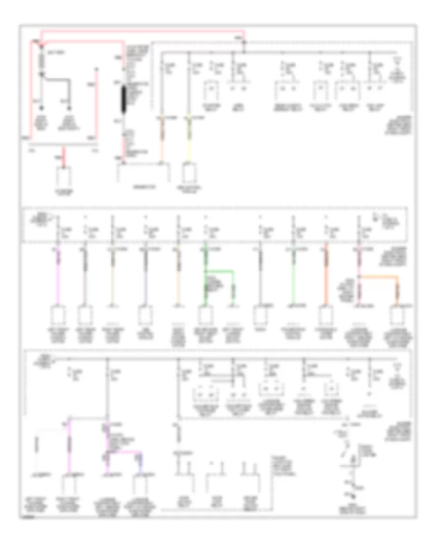
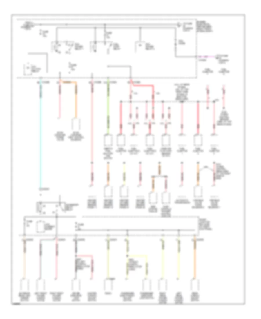
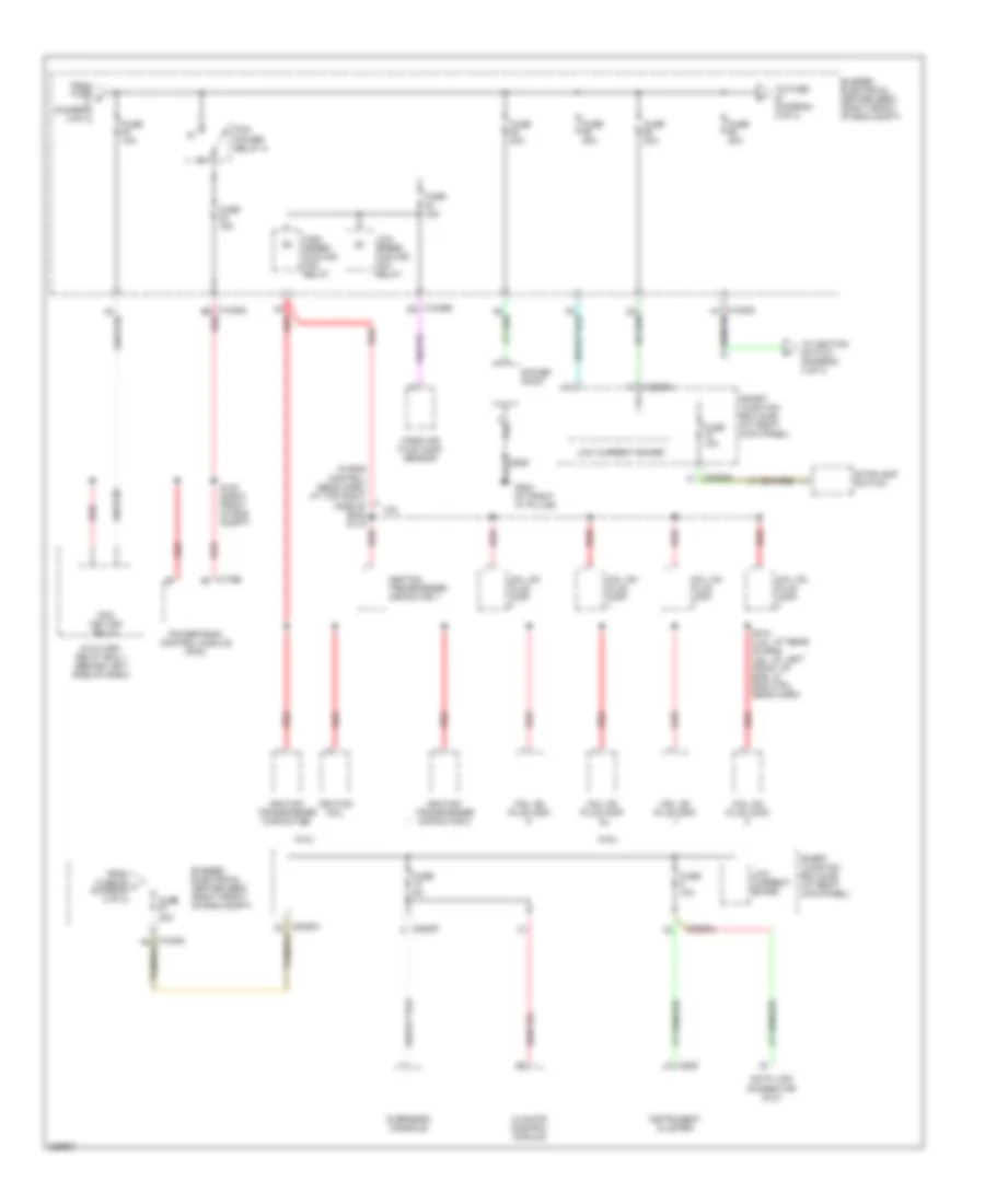
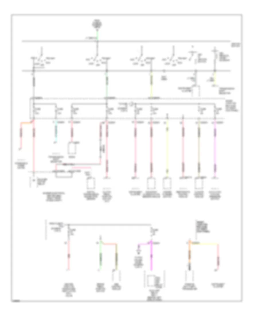
POWER DISTRIBUTION Power Distribution Wiring Diagram (1 of 4) for Ford Mustang GT 2006 List of elements for Power Distribution Wiring Diagram (1 of 4) for Ford Mustang GT 2006: 69 (4.0l) s118 s111 (4.6l) (in generator harn) red (in main harn, behind right kick panel) s221 1035a d5 4.0l 4.6l A/c clutch relay Abs control module Battery Blower motor relay Bussed electrical center (bec) (right front of eng compt) C175b C2280h C290d C2993a C2994a C4157a C4158a C4159a C4160a Convertible top lower relay Convertible top raise relay Door lock relay Door unlock relay Driver door unlock relay Driver side front seat adjust switch Fog lamp relay From fuse 58 a (diagram 1 of 4) From fuse 9 b (diagram 1 of 4) Front cigar lighter Fuse 10a Fuse 15a Fuse 20a Fuse 25a Fuse 30a Fuse 40a G106 (right side of eng) G107 (right side of eng compt) G200 (behind right side of dash) Generator Harn, at right rocker panel) High beam relay High speed engine cooling fan relay Horn relay Left front channel subwoofer amplifier Left front lumbar adjust switch Left front power window motor Left rear power window motor Low speed engine cooling fan relay Luggage compartment left inboard subwoofer amplifier Luggage compartment left outboard subwoofer amplifier Luggage compartment lid release relay Luggage compartment right inboard subwoofer amplifier Luggage compartment right outboard subwoofer amplifier Powertrain control module Radio Rear window defrost relay Red Right front channel subwoofer amplifier Right front power window motor Right rear power window motor S200 Seat) Smart junction box (sjb) (at right kick panel) Starter motor Starter relay To fuse 16 (diagram 1 of 4) To fuse 44 (diagram 2 of 4) To fuse 5 (diagram 1 of 4) Windshield wiper motor Power Distribution Wiring Diagram (2 of 4) for Ford Mustang GT 2006 List of elements for Power Distribution Wiring Diagram (2 of 4) for Ford Mustang GT 2006: 55 (4.0l: at rear of eng, 4.6l: at top right side of eng, in eng ctrl sens harn) s107 4.0l 4.6l A/c clutch relay Accessory delay relay Automatic transmission Bussed electrical center (bec) (right front of eng compt) C1035a C1035b C1035b b2 C2280g C2280h C290d Driver side door lock switch Egr system module Evap canister purge valve Evap canister vent control solenoid Exterior rear view mirror switch From fuse 2 c (diagram 1 of 4) Fuel injector Fuel injector 5 (w/ a/t) Fuel injector 6 (w/ a/t) Fuel pump relay Fuse 10a Fuse 15a Fuse 5a Heated oxygen sensor (ho2s) 11 Heated oxygen sensor (ho2s) 12 Heated oxygen sensor (ho2s) 21 Heated oxygen sensor (ho2s) 22 Inertia fuel shutoff (ifs) switch Inlet manifold runner control module Left front power window motor Left rear power window motor Low current board Mass air flow (maf) sensor (w/ a/t) Master window adjust switch Passenger side door lock switch Passenger side window adjust switch Pcm diode Pcm power relay 1 Pcm power relay 2 Radio Rear window adjust switch Red Right front power window motor Right rear power window motor S101 (in eng control sens harn, at top right side of eng) S109 (in eng control sensor harn, at top rear of eng) S603 (in right window regulator harn) Smart junction box (sjb) (at right kick panel) To fuse (diagram 3 of 4) To fuse (diagram 4 of 4) Variable valve timing solenoid 1 Variable valve timing solenoid 2 Power Distribution Wiring Diagram (3 of 4) for Ford Mustang GT 2006 List of elements for Power Distribution Wiring Diagram (3 of 4) for Ford Mustang GT 2006: 45 (4.0l) (4.6l) (in eng control sens harn, at top right side of eng) s119 4.6l Auxiliary relay box 1 (behind left side of dash) Bussed electrical center (bec) (right front of eng compt) C1035a b6 red C1035b d5 C175b C220 C2280a C2280f C2280h Climate control module Coil on plug (cop) Data link connector (dlc) From fuse 68 f (diagram 3 of 4) From fuse d (diagram 2 of 4) Fuse 10a Fuse 15a Fuse 20a Fuse 30a Fuse 5a G203 (at right "a" pillar) High speed cooling fan relay Ignition coil Ignition transformer capacitor Ignition transformer capacitor 1 Ignition transformer capacitor 2 Instrument cluster Low current board Low speed cooling fan relay Mass air flow (maf) sensor Overhead console Pcm key-off relay Pcm power relay 2 Power point Powertrain control module (pcm) Red S104 (4.0l: at rear of eng, 4.6l: at left front of eng, in eng ctrl sens harn) S120 (right front of eng compt) Smart junction box (sjb) (at right kick panel) Stoplamp switch To fuse (diagram 3 of 4) To ignition switch (diagram 4 of 4) Power Distribution Wiring Diagram (4 of 4) for Ford Mustang GT 2006 List of elements for Power Distribution Wiring Diagram (4 of 4) for Ford Mustang GT 2006: 46 (not used) A/c clutch cycling pressure switch Abs control module Acc Auxiliary relay box 1 (behind left side of dash) Blower motor relay Brake pedal position switch Bussed electrical center (bec) (right front of eng compt) C1035a a9 C1035b b9 C2041a C2280a C2280h C290d C294a Climate control module Clutch pedal position switch (m/t) Digital transmission range (dtr) sensor From fuse 68 (diagram 3 of 4) From fuse j (diagram 4 of 4) Fuse 10a Fuse 5a Hazard flasher switch Heated positive crankcase ventilation (pcv) valve Ignition switch Instrument cluster Jumper Key in ignition switch Key removal inhibit solenoid Lock Nca Occupant classification sensor module Off Passive anti-theft transceiver Pcm key- off relay diode Radio Red Restraints control module Run Smart junction box (sjb) (at right kick panel) Smart smart junction junction box (sjb) box (sjb) (at right (at right kick panel) kick panel) Start To fuse (diagram 4 of 4) To pcm power diode, (diagram 2 of 4) Transmission shift selector Windshield wiper motor
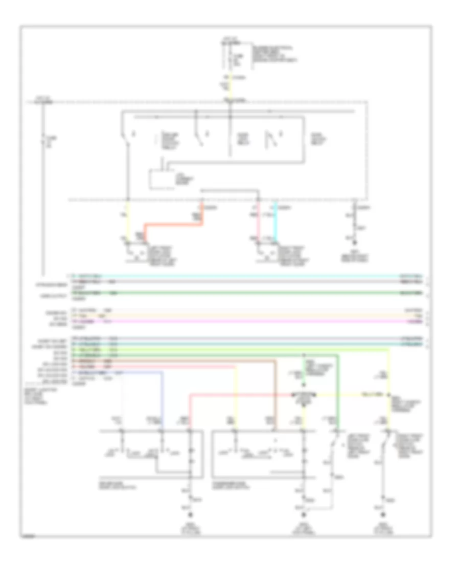
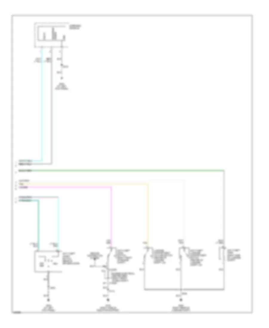
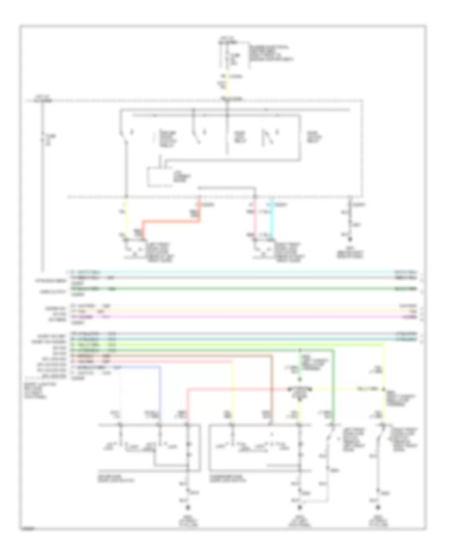
POWER DOOR LOCKS Door Lock Wiring Diagram (1 of 2) for Ford Mustang GT 2006 List of elements for Door Lock Wiring Diagram (1 of 2) for Ford Mustang GT 2006: 46 Bussed electrical center (bec) (right front of engine compartment) C2280a C2280c C2280d C2280e C2280f C2280g C2280h D9 c1035a Disarm sw Door lock relay Door unlock relay Driver door unlock relay Driver side door lock switch Fuse 20a Fuse 5a G201 (behind right side of dash) G203 (at right "a" pillar) G204 (at right "a" pillar) Horn output Hot at all times Inhibit sw disarm Inhibit sw set Interior lights system Intrusion sens Left front door ajar switch (rear of left front door) Left front door lock actuator (rear of left front door) Lock Low current board Passenger side door lock switch Red Right front door ajar switch (rear of right front door) Right front door lock actuator (rear of right front door) S201 S203 (at left kick panel) S215 S222 S503 S604 (right window regulator harness) Smart junction box (sjb) (at right kick panel) Sw lock sig Sw sens Sw sig Sw unlock sig Tan Un- lock Door Lock Wiring Diagram (2 of 2) for Ford Mustang GT 2006 List of elements for Door Lock Wiring Diagram (2 of 2) for Ford Mustang GT 2006: 24 Anti-theft hood switch (right front of engine compt) Anti-theft horn (right side of luggage compt) Anti-theft inhibit switch (rear of driver's door) Anti-theft luggage compartment switch (center of luggage compt lid) Arm Bussed electrical center (bec) (right front of eng compt) C1035c D11 Dis- arm E11 c1035c G100 (right side of radiator support) G204 (at left kick panel) G402 (right rear of luggage compt) Gnd Ground distribution system Intrusion sense Luggage compartment lid ajar switch (center of luggage compt lid) Overhead console S112 S215 S406 S503 Tan Vbatt
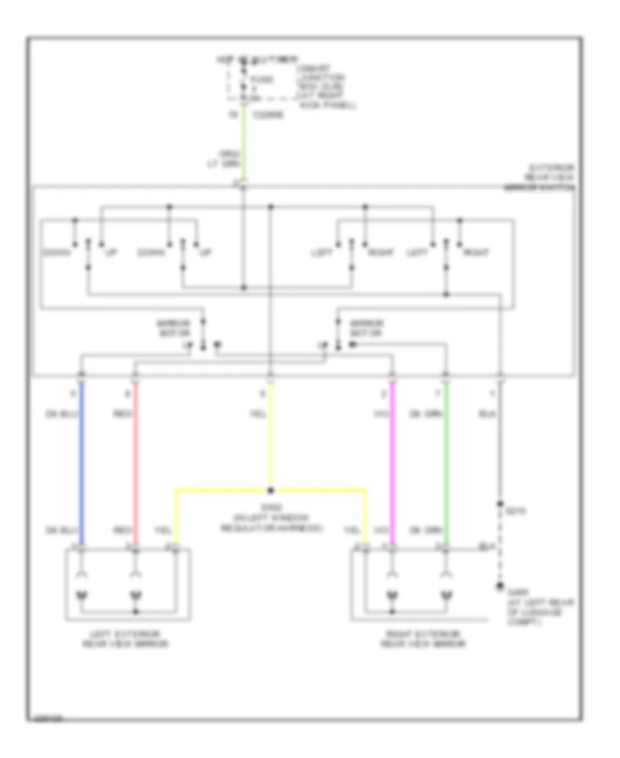
POWER MIRRORS Power Mirrors Wiring Diagram for Ford Mustang GT 2006 List of elements for Power Mirrors Wiring Diagram for Ford Mustang GT 2006: 15 C2280e Down Exterior rear view mirror switch Fuse 5a G400 (at left rear of luggage compt) Hot at all times Left Left exterior rear view mirror Mirror motor Red Right Right exterior rear view mirror S215 S502 (in left window regulator harness) Smart junction box (sjb) (at right kick panel)
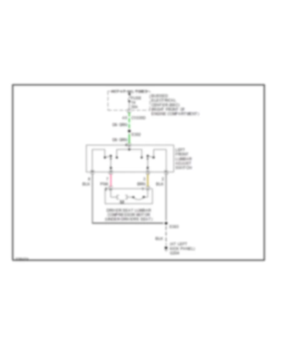
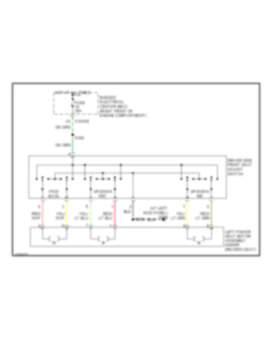
POWER SEATS Lumbar Wiring Diagram for Ford Mustang GT 2006 List of elements for Lumbar Wiring Diagram for Ford Mustang GT 2006: 10 (at left kick panel) g204 A5 c1035d Bussed electrical center (bec) (right front of engine compartment) Driver seat lumbar compressor motor (under driver's seat) Fuse 30a Hot at all times Left front lumbar adjust switch Pnk S302 S303 Power Seat Wiring Diagram for Ford Mustang GT 2006 List of elements for Power Seat Wiring Diagram for Ford Mustang GT 2006: 12 (at left kick panel) g204 A5 c1035d Bussed electrical center (bec) (right front of engine compartment) Driver side front seat adjust switch Fuse 30a Fwd/ back Hot at all times Left power seat motor assembly (under driver's seat) S302 S303 Up/down frt Up/down rr
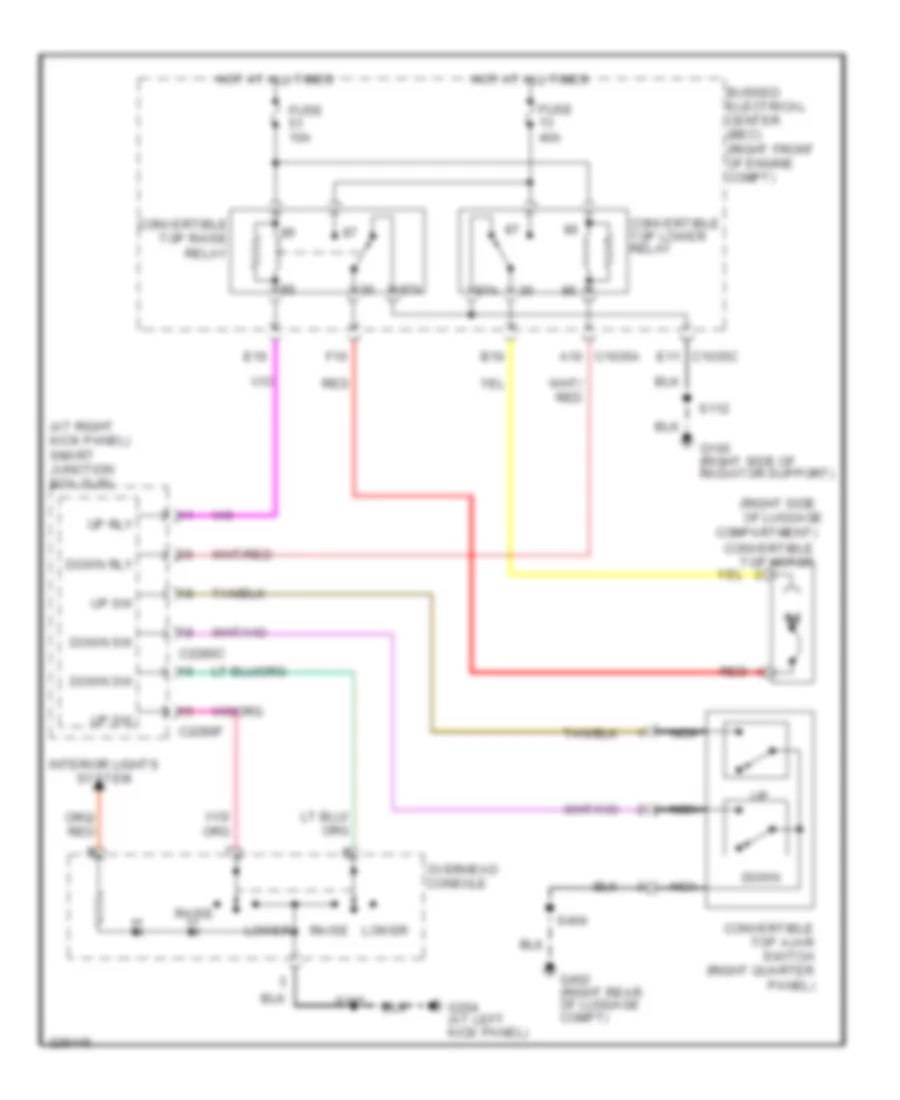
POWER TOP/SUNROOF Convertible Top Wiring Diagram for Ford Mustang GT 2006 List of elements for Convertible Top Wiring Diagram for Ford Mustang GT 2006: 37 (at right kick panel) smart junction box (sjb) (right side 87a A10 c1035a B10 Bussed electrical center (bec) (right front of engine compt) C2280c C2280f Compartment) Convertible top ajar switch (right quarter panel) Convertible top lower relay Convertible top motor Convertible top raise relay Down Down rly Down sw E10 E11 c1035c F10 Fuse 10a Fuse 40a G100 (right side of radiator support) G204 (at left kick panel) G402 (right rear of luggage compt) Hot at all times Interior lights system Lower Nca Of luggage Overhead console Raise Red S112 S215 S404 Up rly Up sw
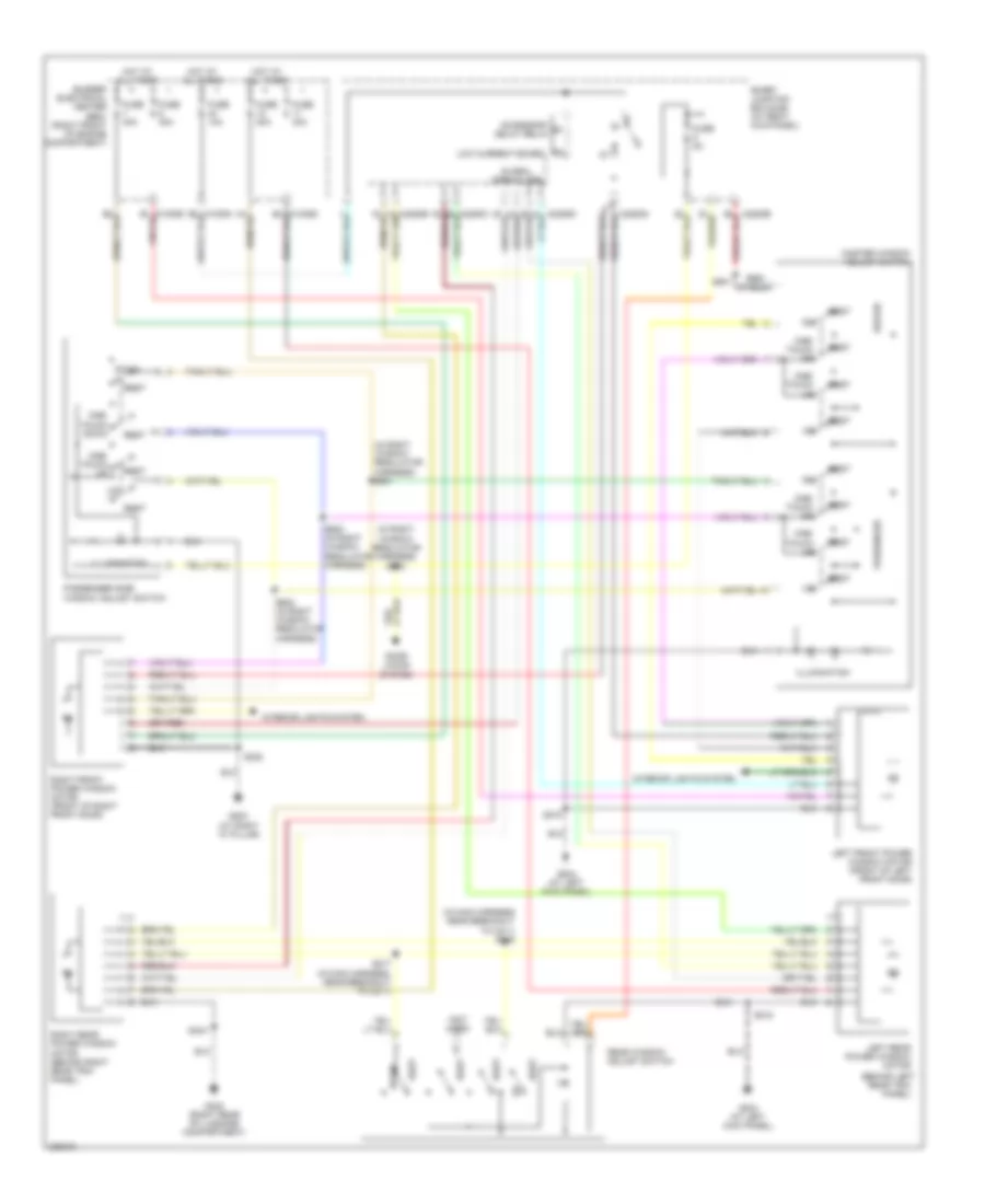
POWER WINDOWS Power Windows Wiring Diagram for Ford Mustang GT 2006 List of elements for Power Windows Wiring Diagram for Ford Mustang GT 2006: 45 (behind left (in main harness near breakout to c211) s216 (in right window regulator harness) s601 (in right window regulator harness) s603 (not used) Accessory delay relay Bussed electrical center (bec) (right front of engine compartment) C2280d C2280e C2280g Door locks system Down Driver Fuse 10a Fuse 30a Fuse 5a G203 (at right "a" pillar) G204 (at left kick panel) G402 (right rear of luggage compartment) Global open/close Hot at all times Illumination Interior lights system Left front power window motor (front of left front door) Left rear power window motor Low current board Master window adjust switch One- touch dn One- touch down One- touch up Passenger Passenger side window adjust switch Rear trim panel) Rear window adjust switch Rest Right front power window motor (front of right front door) Right rear power window motor (behind right rear trim panel) S215 S217 (in main harness, near breakout to c211) S222 S404 S501 S600 (in right window regulator harness) S602 (in right window regulator harness) Smart junction box (sjb) (at right kick panel)
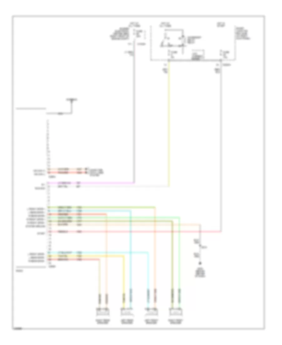
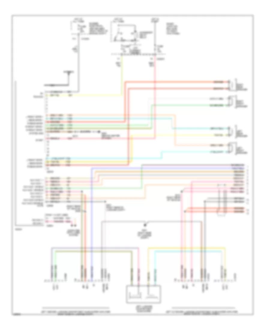
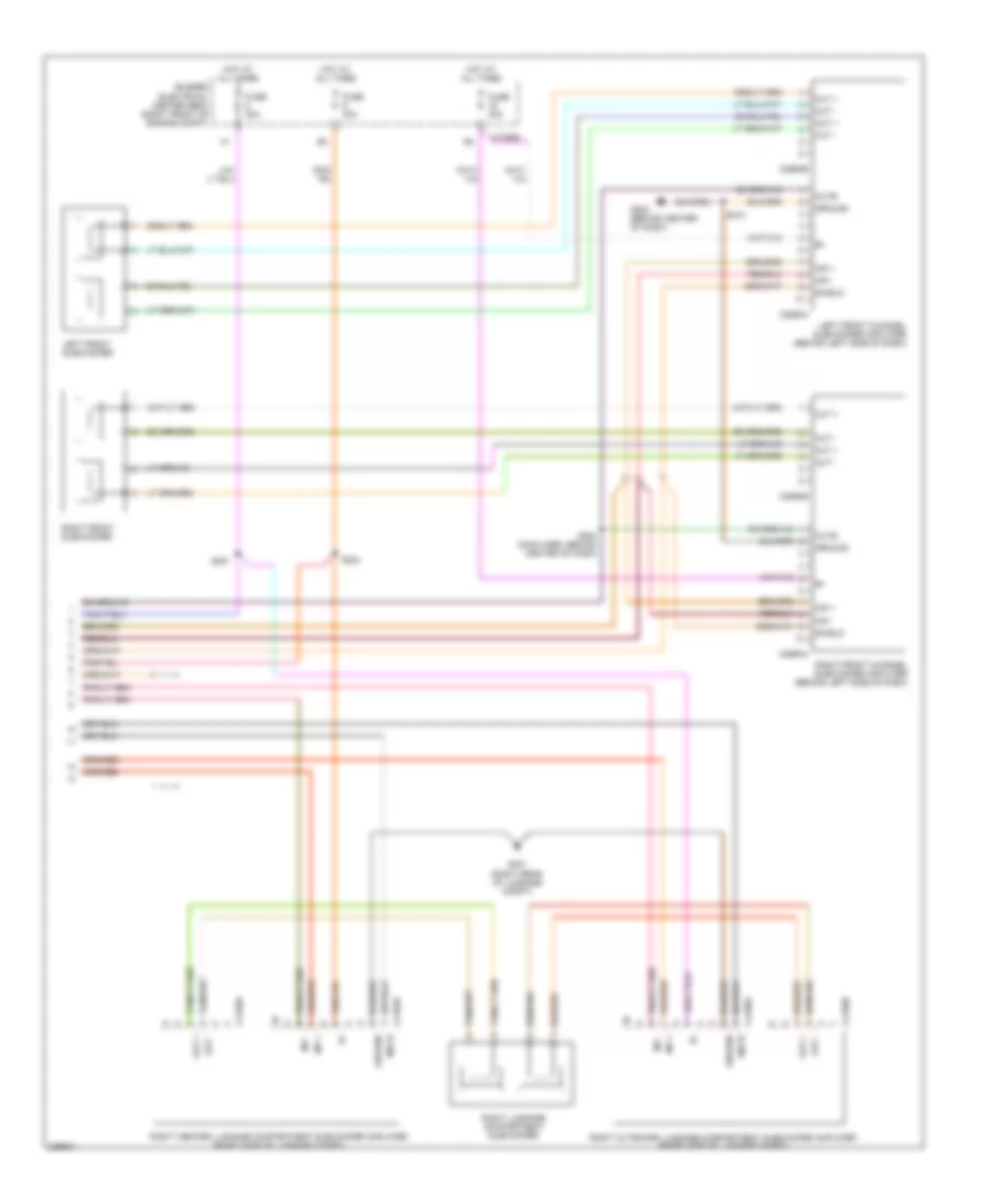
RADIO Base Radio Wiring Diagram for Ford Mustang GT 2006 List of elements for Base Radio Wiring Diagram for Ford Mustang GT 2006: 38 Accessory delay relay Antenna B + Bussed electrical center (bec) (right front of engine compt) C1035a C2280a C290a C290d Computer data lines system F11 Fuse 10a Fuse 20a Fuse 5a G202 (behind center of dash) Hot at all times Hot in start L front spkr + L front spkr - L rear spkr + L rear spkr - Left front speaker Left rear speaker Low current board Ms can (+) Ms can (-) Nca R front spkr + R front spkr - R rear spkr - R rear spkr+ Radio Right front speaker Right rear speaker Run/acc S210 Smart junction box (sjb) (at right kick panel) Start System ground Premium Sound Radio Wiring Diagram (1 of 2) for Ford Mustang GT 2006 List of elements for Premium Sound Radio Wiring Diagram (1 of 2) for Ford Mustang GT 2006: 64 (pins 1-14 not used) (right rear of vehicle) s409 Accessory delay relay Antenna Aux aud 1 + Aux aud 1 - Aux aud 1 enable Aux aud 1 shield Aux aud 2 + Aux aud 2 - Aux aud 2 enable/ mute Aux aud 2 shield Bussed electrical center (bec) (right front of engine compt) C1035a C2280a C290a C290b C290d C4157a C4157b C4158a C4158b Computer data lines system F11 Fuse 10a Fuse 20a Fuse 5a G202 (behind center of dash) G401 (right rear of luggage compt) Ground Hot at all times Hot in start Inp + Inp - L front spkr + L front spkr - L rear spkr + L rear spkr - Left front speaker Left inboard luggage compartment subwoofer amplifier (right side of luggage compt) Left luggage compartment subwoofer Left outboard luggage compartment subwoofer amplifier (right side of luggage compt) Left rear speaker Low current board Ms can (+) Ms can (-) Mute Nca Out + Out - R front spkr + R front spkr - R rear spkr - R rear spkr+ Radio Right front speaker Right rear speaker Run/acc S210 S401 (right rear of luggage compt) S410 (right rear of vehicle) Smart junction box (sjb) (at right kick panel) Start System gnd Premium Sound Radio Wiring Diagram (2 of 2) for Ford Mustang GT 2006 List of elements for Premium Sound Radio Wiring Diagram (2 of 2) for Ford Mustang GT 2006: 33 (right rear of luggage compt) Bussed electrical center (bec) (right front of engine compt) C1035d C2993a C2993b C2994a C2994b C4159a C4159b C4160a C4160b Fuse 30a G202 (behind center of dash) G401 Ground Hot at all times Inp + Inp - Left front channel subwoofer amplifier (behind left side of dash) Left front subwoofer Mute Out + Out - Right front channel subwoofer amplifier (behind left side of dash) Right front subwoofer Right inboard luggage compartment subwoofer amplifier (right side of luggage compt) Right luggage compartment subwoofer Right outboard luggage compartment subwoofer amplifier (right side of luggage compt) S204 (main harn, behind center of dash) S210 S221 S224 Shield
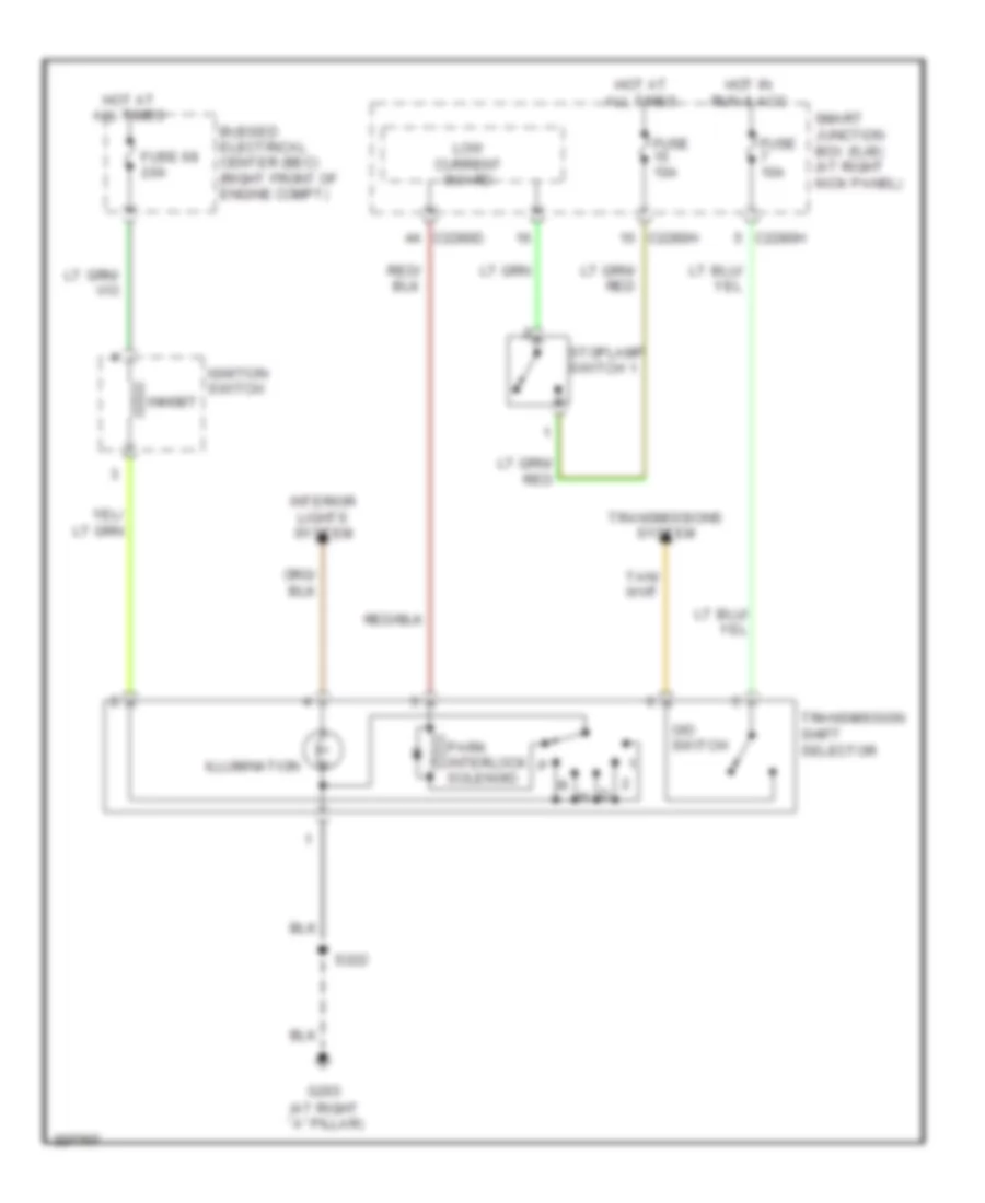
SHIFT INTERLOCK Shift Interlock Wiring Diagram for Ford Mustang GT 2006 List of elements for Shift Interlock Wiring Diagram for Ford Mustang GT 2006: 21 (at right ``a" pillar) Bussed electrical center (bec) (right front of engine compt) C2280d C2280h Fuse 10a Fuse 68 20a G203 Hot at all times Hot in run & acc Ignition switch Illumination Inhibit Interior lights system Low current board O/d switch Park interlock solenoid S222 Smart junction box (sjb) (at right kick panel) Stoplamp switch 1 Transmission shift selector Transmissions system
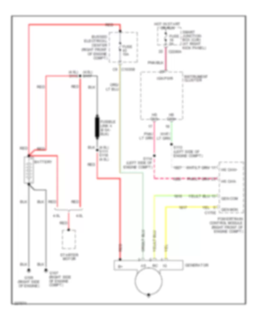
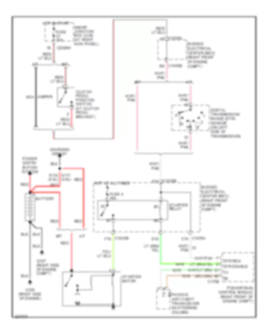
STARTING/CHARGING Charging Wiring Diagram for Ford Mustang GT 2006 List of elements for Charging Wiring Diagram for Ford Mustang GT 2006: 27 (4.0l) s117 (4.6l) s110 4.0l 4.6l Battery Bussed electrical center (right front of engine compt) C1035b c9 C175e C2280a Fuse 10a Fuse 5a G106 (right side of engine) G107 (right side of engine compt) Gen com Gen mon Generator Hot in start or run Hs can+ Hs can- Ign pwr Instrument cluster Powertrain control module (right front of engine compt) Red S113 (left side of engine compt) S114 (left side of engine compt) Smart junction box (cjb) (at right kick panel) Starter motor Starting Wiring Diagram for Ford Mustang GT 2006 List of elements for Starting Wiring Diagram for Ford Mustang GT 2006: 33 (4.0l) A/t Battery Bussed electrical center (bec) (right front of engine compt) C1035a a9 C1035a c10 C1035b b9 C1035b e10 C1035b f10 C175b C2280h Charging circuit Clutch pedal position switch (at clutch pedal bracket) D12 Digital transmission range (dtr) sensor (on left side of transmission) Fuse 10a Fuse 4 30a G106 (right side of engine) G107 (right side of engine compt) Hot at all times Hot in start Jumper nca M/t Power distri- bution system Powertrain control module (right front of engine compt) Red Rx passive anti-theft transceiver (in steering column) S117 s110 (4.6l) Smart junction box (cjb) (at right kick panel) Starter motor Starter relay Str enable Str req
SUPPLEMENTAL RESTRAINTS Supplemental Restraints Wiring Diagram (1 of 2) for Ford Mustang GT 2006 List of elements for Supplemental Restraints Wiring Diagram (1 of 2) for Ford Mustang GT 2006: 47 (at right "a" pillar) g205 (front of left quarter panel) (in main harn, behind right kick panel) s220 (right quarter panel) Air bag monitor Buckle status C175b C2041a C2041b C2280a C2280h Data link connector (dlc) (behind dash, left of steering column) Dr seat track sens feed Driver safety belt retractor pretensioner Driver's safety belt buckle switch (in driver's seat belt buckle) Driver's seat position sensor (under driver's seat) Drv buckle sw Drv sn feed Drv sn rtn Fuse 10a G205 (at right "a" pillar) Gnd Hot in start or run Hs can+ Hs can- Instrument cluster Iso Pad ind Pass buckle sw Pass sn feed Pass sn rtn Passenger air bag deactivation (pad) indicator Passenger safety belt retractor pretensioner Passenger's safety belt buckle switch (in passenger's seat belt buckle) Powertrain control module (right front of engine compt) Primary ril Red Restraints control module (behind lower center of dash) S220 (in main harn, behind right kick panel) S301 (under driver's seat) Sig feed Sig rtn Smart junction box (sjb) (at right kick panel) Sn feed Sn rtn Tas Vpwr Supplemental Restraints Wiring Diagram (2 of 2) for Ford Mustang GT 2006 List of elements for Supplemental Restraints Wiring Diagram (2 of 2) for Ford Mustang GT 2006: 31 (under passenger's seat) occupant classification sensor module Bts Bts rtn Bts vref Clock spring (below steering wheel) Driver 1 side impact sensor (on left rocker panel) Driver air bag unit Front impact severity sensor (front of engine compartment) G205 (at right "a" pillar) Gnd Hs can+ Hs can- Left side air bag module (on driver's seat) Nca Occupant classification sensor (ocs) (under Passenger 1 side impact sensor (on right rocker panel) Passenger safety belt tension sensor (at right "b" pillar) Passenger's Passenger's air bag module (right side of dash) Red Right side air bag module (on passenger's seat) S220 (in main harn, behind right kick panel) Seat) Shorting bar Stage 1 Stage 2 Tan/ red Tan/red Vign Vout Vref
TRANSMISSION A/T Wiring Diagram (1 of 2) for Ford Mustang GT 2006 List of elements for A/T Wiring Diagram (1 of 2) for Ford Mustang GT 2006: 61 (4.6l) (4.0l) (left side of engine compt) (on left rear side of transmission) output shaft speed (oss) sensor (on throttle body assembly) (top left side of transmission) intermediate shaft speed (iss) sensor (top left side of transmission) turbine shaft speed (tss) sensor Accel ped pos 1 Accel ped pos 2 Accel ped pos 3 Accelerator pedal position sensor (below left side of dash) Anti-lock brakes system Brake pedal position switch (on brake pedal support) Brk ped pos sw Bussed electrical center (bec) (right front of engine compt) C1035a C1035b C1035b f6 red C11 C175b C175e Computer data lines system Data link connector (dlc) (behind dash, left of steering column) Engine controls system Fuel pump relay Fuse 10a Fuse 15a Fuse 5a G100 (right side of radiator support) Hot at all times Hot in run or acc Hot in start or run Hs can + Hs can - Intake air temp Maf sig Maf sig rtn Pcm power diode Pcm power relay Powertrain control module (right front of engine compt) Red Ref vol Ref voltage S101 S102 s106 (in engine control sensor harness, on top of transmission) S109 S112 S113 S114 S212 (left rear of engine compt) Sens 1 Sens 2 Sens 3 Sens rtn Sens vref Sig rtn Smart junction box (sjb) (at right kick panel) Throttle position sensor (tps) Tps ref volt Tps sig 1 Tps sig 2 Transmission shift selector A/T Wiring Diagram (2 of 2) for Ford Mustang GT 2006 List of elements for A/T Wiring Diagram (2 of 2) for Ford Mustang GT 2006: 28 (on left side of transmission) digital transmission range (dtr) sensor A/t Automatic transmission C175t Dtr sens tr1 Dtr sens tr2 Dtr sens tr3a Dtr sens tr4 Engine controls system G102 (on right front of engine compt) Iss sens sig M/t Mass air flow (maf) sensor (on air cleaner assembly) Oss sens sig Pca sol a ctrl Pcb sol b ctrl Pcc sol c ctrl Powertrain control module (right front of engine compt) Red S108 Shift sol a ctrl Shift sol b ctrl Shift sol c ctrl Shift sol d ctrl Tcc sol ctrl Tft sens sig Trans od cancel Tss sens sig
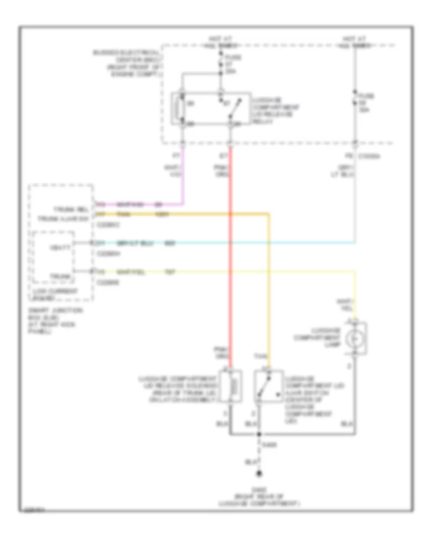
TRUNK, TAILGATE, FUEL DOOR Trunk Release Wiring Diagram for Ford Mustang GT 2006 List of elements for Trunk Release Wiring Diagram for Ford Mustang GT 2006: 21 Bussed electrical center (bec) (right front of engine compt) C2280c C2280e C2280h F8 c1035a Fuse 20a Fuse 30a G402 (right rear of luggage compartment) Hot at all times Low current board Luggage compartment lamp Luggage compartment lid ajar switch (center of luggage compartment lid) Luggage compartment lid release relay Luggage compartment lid release solenoid (rear of trunk lid, on latch assembly) S406 Smart junction box (sjb) (at right kick panel) Tan Trunk Trunk ajar sw Trunk rel Vbatt
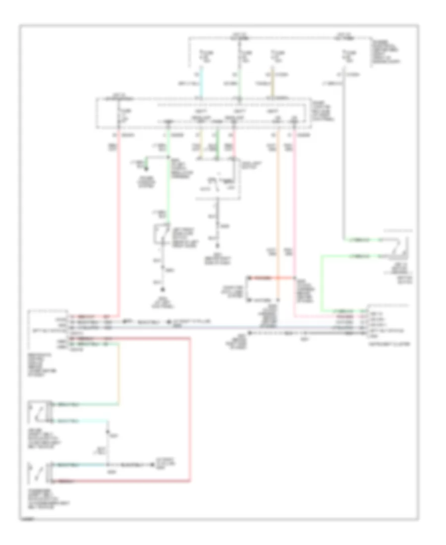
WARNING SYSTEMS Warning Systems Wiring Diagram for Ford Mustang GT 2006 List of elements for Warning Systems Wiring Diagram for Ford Mustang GT 2006: 49 (at right "a" pillar) g205 Auto Bussed electrical center (bec) (right front of engine compt) C1035a C2041a C2041b C2280a C2280b C2280e C2280h Computer data lines system Driver safety belt buckle switch (in driver's seat belt buckle) Fuse 10a Fuse 20a Fuse 30a G201 (behind right side of dash) G204 (at left kick panel) Gnd Headlamp off Headlamp on Hot at all times Hot in start or run Ignition switch Instrument cluster Key in Key in ignition switch Left front door ajar switch (rear of left front door) Low Main light switch Ms can + Ms can - Off Park Passenger safety belt buckle switch (in passenger's seat belt buckle) Power windows system Restraints control module (behind lower center of dash) S201 S205 (in main harness, behind center of dash) S206 (in main harness, behind center of dash) S209 S220 S301 S500 (in left window regulator harness) S503 Sfty blt status Smart junction box (sjb) (at right kick panel) Vbatt Vpwr Vref
WIPER/WASHER Wiper/Washer Wiring Diagram for Ford Mustang GT 2006 List of elements for Wiper/Washer Wiring Diagram for Ford Mustang GT 2006: 28 1. wash 2. off 3. int wipe 4. low 5. high 6. int 1 7. int 2 8. int 3 9. int 4 10. int 5 Bussed electrical box (bec) (right front of engine compt) C1035d C2280h Electronics Front wash Front washer relay Fuse 10a Fuse 30a G201 (behind right side of dash) G203 (at right "a" pillar) G204 (at left kick panel) Hall sensor Hi/lo speed relay Hot at all times Hot in run or acc Off Red Run/ park Run/ park relay S209 S215 S222 Smart junction box (sjb) (at right kick panel) Wash Windshield washer pump motor (right front of vehicle) Windshield wiper motor (on left side of firewall) Wiper/ washer switch