Diagram sections — 27 (57 total)
AIR CONDITIONING ANTI-LOCK BRAKES BODY COMPUTER COMPUTER DATA LINES COOLING FAN CRUISE CONTROL DEFOGGERS ENGINE PERFORMANCE EXTERIOR LIGHTS GROUND DISTRIBUTION HEADLIGHTS HORN INSTRUMENT CLUSTER INTERIOR LIGHTS POWER DISTRIBUTION POWER DOOR LOCKS POWER MIRRORS POWER SEATS POWER TOP/SUNROOF POWER WINDOWS RADIO SHIFT INTERLOCKS STARTING/CHARGING SUPPLEMENTAL RESTRAINTS TRANSMISSION WARNING SYSTEMS WIPER/WASHER
AIR CONDITIONING
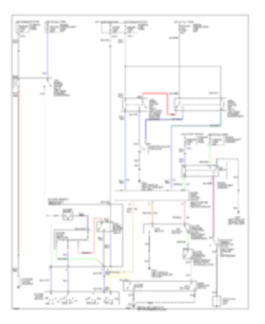
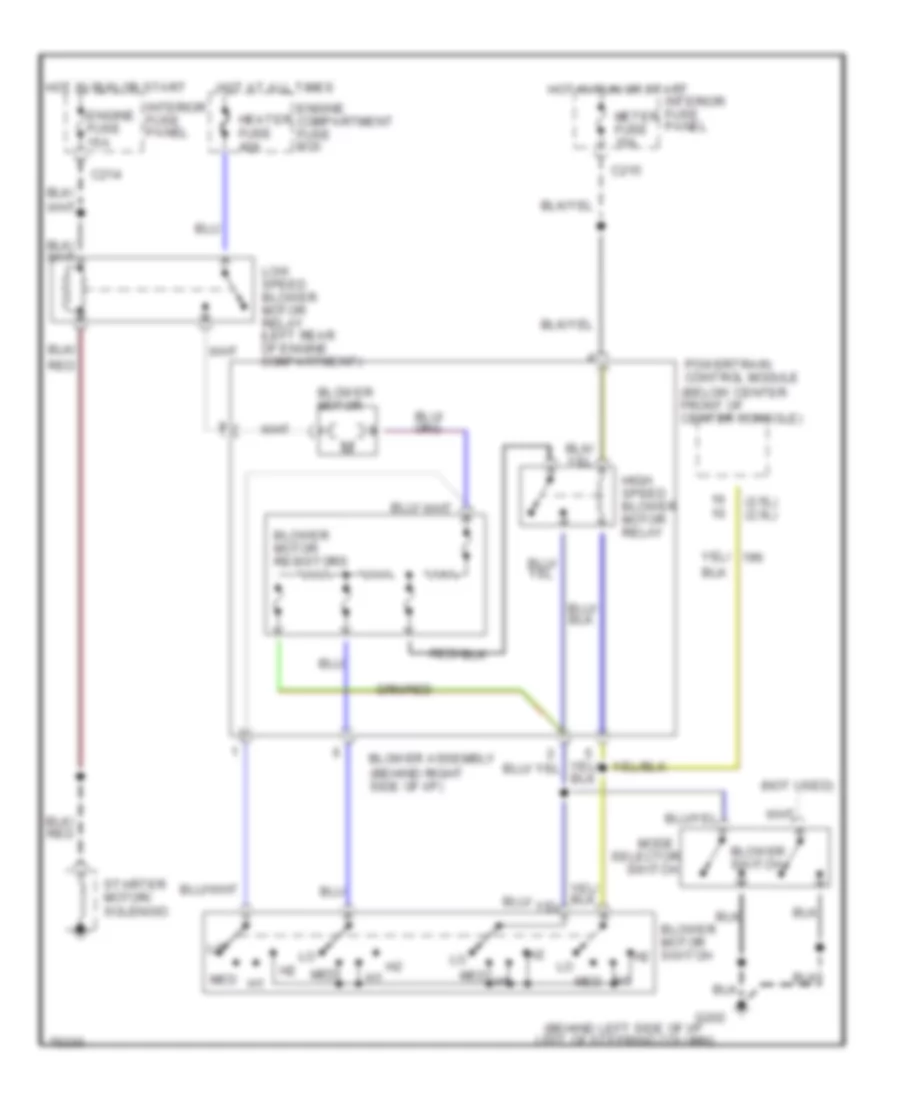
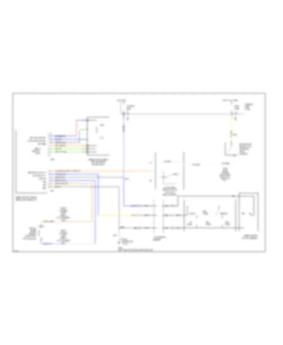
2.0L 2.0L, A/C Wiring Diagram for Ford Probe SE 1996 List of elements for 2.0L, A/C Wiring Diagram for Ford Probe SE 1996: 47 (behind left side of i/p left of steering column) (behind right side of i/p) (below center front of center console) (left front of vehicle, near left fog lamp) (left rear of engine compartment) (right front of engine, on compressor) A/c clutch field coil A/c clutch switch A/c clutch thermal protection switch A/c high pressure cutout/fan switch (right front of engine compartment) A/c relay A/c switch Aircond fuse 15a Aircond fuse 40a Blower assembly Blower motor Blower motor resistors Blower motor switch Blower switch C214 C215 Clutch cycling pressure switch (right rear of engine compt on accumulator) Cooling fan fuse 40a Electric cooling fan motor Engine compartment fuse box Engine fuse 15a Fan switch G100 G100 (left front of vehicle, near left fog lamp) G202 Heater fuse 40a High speed blower motor relay High speed cooling fan relay Hot at all times Hot in accy or run Hot in run or start Interior fuse panel Lo med Low speed blower motor relay (left rear of engine compartment) Low speed cooling fan relay (left front of vehicle on upper radiator support) Med Meter fuse 15a Mode selector switch Nca Power- train control module Red Starter motor/ solenoid Heater Wiring Diagram for Ford Probe SE 1996 List of elements for Heater Wiring Diagram for Ford Probe SE 1996: 29 (2.5l) (2.0l) (behind left side of i/p left of steering column) (behind right side of i/p) (not used) Blower assembly Blower motor Blower motor resistors Blower motor switch Blower switch C214 C215 Engine compartment fuse box Engine fuse 15a G202 Heater fuse 40a High speed blower motor relay Hot at all times Hot in run or start Interior fuse panel Low speed blower motor relay (left rear of engine compartment) Med Meter fuse 15a Mode Powertrain control module (below center front of center console) Red Red/ Selector Starter motor/ solenoid Switch
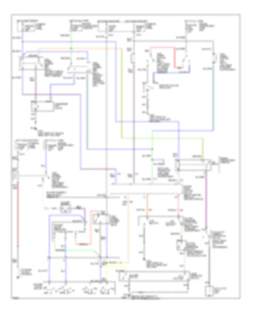
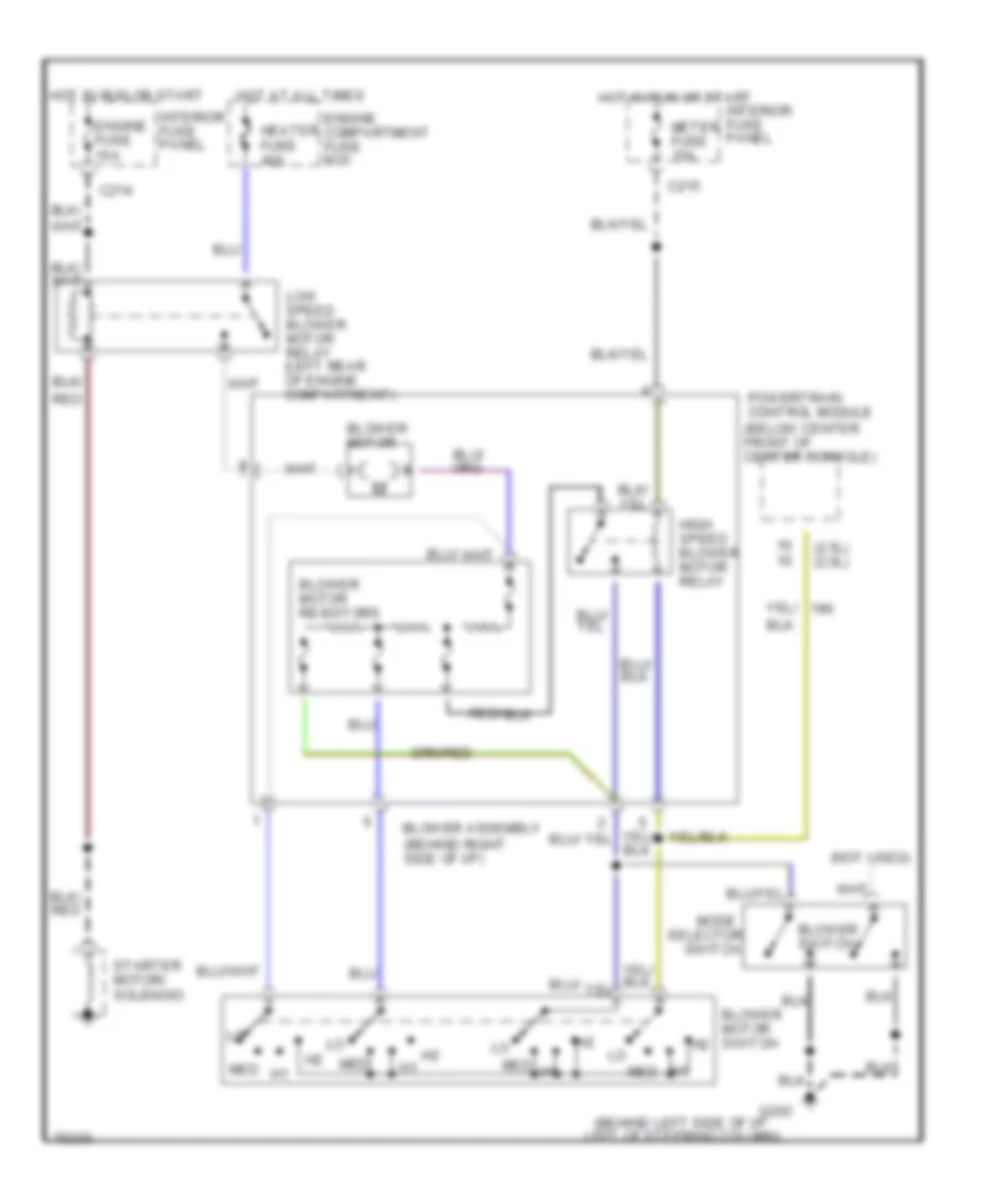
2.5L 2.5L, A/C Wiring Diagram for Ford Probe SE 1996 List of elements for 2.5L, A/C Wiring Diagram for Ford Probe SE 1996: 47 (behind left side of i/p left of steering column) (behind right side of i/p) (left rear of engine compartment) (right front of engine, on compressor) A/c clutch field coil A/c clutch switch A/c clutch thermal protection switch A/c high pressure cutout/fan switch (right front of engine compartment) A/c relay A/c switch Aircond fuse 15a Aircond fuse 40a Blower assembly Blower motor Blower motor resistors Blower motor switch Blower switch C214 C215 Clutch cycling pressure switch (right rear of engine compt on accumulator) Condenser fan motor Cooling fan fuse 40a Data link connector (left side of engine compartment) Electric cooling fan motor Engine compartment fuse box Engine fuse 15a Fan switch G100 (left front of vehicle, near left fog lamp) G202 Heater fuse 40a High speed blower motor relay High speed conden- ser fan relay (on right side of engine compart- ment fuse box) High speed cooling fan relay Hot at all times Hot in accy or run Hot in run or start Interior fuse panel Low speed blower motor relay (left rear of engine compartment) Low speed conden- ser fan relay (on right side of engine compart- ment fuse box) Low speed cooling fan relay (left front of vehicle on upper radiator support) Med Meter fuse 15a Mode selector switch Nca Power- train control module (below center front of center console) Red Starter motor/ solenoid Heater Wiring Diagram for Ford Probe SE 1996 List of elements for Heater Wiring Diagram for Ford Probe SE 1996: 29 (2.5l) (2.0l) (behind left side of i/p left of steering column) (behind right side of i/p) (not used) Blower assembly Blower motor Blower motor resistors Blower motor switch Blower switch C214 C215 Engine compartment fuse box Engine fuse 15a G202 Heater fuse 40a High speed blower motor relay Hot at all times Hot in run or start Interior fuse panel Low speed blower motor relay (left rear of engine compartment) Med Meter fuse 15a Mode Powertrain control module (below center front of center console) Red Red/ Selector Starter motor/ solenoid Switch
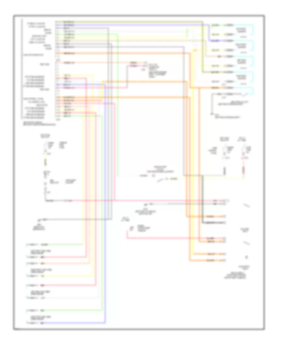
ANTI-LOCK BRAKES Anti-lock Brake Wiring Diagrams for Ford Probe SE 1996 List of elements for Anti-lock Brake Wiring Diagrams for Ford Probe SE 1996: 87 (behind top (left front of vehicle, (left rear of engine compt) (left rear of engine compt.) (left side of engine (near left side of steering column) (partial) (right side of engine (top of brake pedal support) 15a 20a 60a Abs Abs control module Abs hydraulic unit Abs ind ctrl Abs main relay All times Apron) Brake on/off Brake sw input C135 C173 C174 C214 C215 C216 C222 C223 C241 Center of i/p) Cluster Compartment Compartment fuse box) Compt., on fender Connector Data link Engine Fail safe Fail safe rly ctrl Fuse Fuse box G102 G106 G206 Ground Hot at Hot in run Indicator Instrument Interior L fnt brake sensor L fnt valve ctrl L rear brake sensor L rear valve ctrl Left front Left front abs wheel Left rear Left rear abs wheel Meter Nca Near fog lamp) Or start Panel Pnk Pnk 408 Power Pump motor Pump mtr power input Pump mtr relay cntrl Red Red 411 Red 415 Relay Right front Right front abs wheel Right rear Right rear abs wheel Rt fnt brake sensor Rt fnt valve ctrl Rt rear brake sensor Rt rear valve ctrl Solenoid Speed sensor Stop Switch Test conn
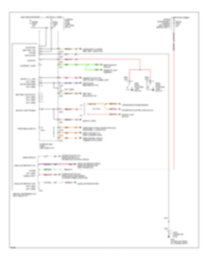
BODY COMPUTER Body Computer Wiring Diagrams for Ford Probe SE 1996 List of elements for Body Computer Wiring Diagrams for Ford Probe SE 1996: 58 (not used) 2.5l only A/t Backup lamp switch Backup lamp/tr sens Backup lamps C201 C204 C213 C214 C215 C217 C301 Central processing unit (left side of i/p) Combination switch (ignition key cylinder lamp) Combination switch, headlamp relay & powertrain control module Combination switch, headlamps & instrument cluster (hi-beam indicator) Courtesy lamps Dome/map lamp assembly Door sw Engine compartment fuse box (left side of engine compt.) G407 (lower left rear of luggage compt.) Headlamp retract (dn) Headlamp retract (up) Headlamp retractors Headlamp retractors & headlamp retractor test connector Headlamps on Hi-beam input Hot at all times Hot in run or start Ign key cyl lamp Ign key reminder Ignition key reminder switch Instrument cluster (seat belt indicator) Instrument panel dimming module & instrument illumination Interior fuse panel (left side of i/p) Joint connector (c400) Left door courtesy lamp switch M/t Meter fuse 15a Module gnd Not used) Park lamp relay & front marker lamps Park/headlamps on Pnk Power Powertrain control module (2.5l) Rear marker lamps & license plate lamps Red Remote entry module Retra fuse 20a Right door courtesy lamp switch Room fuse 15a Run/start Seat belt buckle sw Seat belt buckle switch Seat belt ind Transmission range sensor
COMPUTER DATA LINES
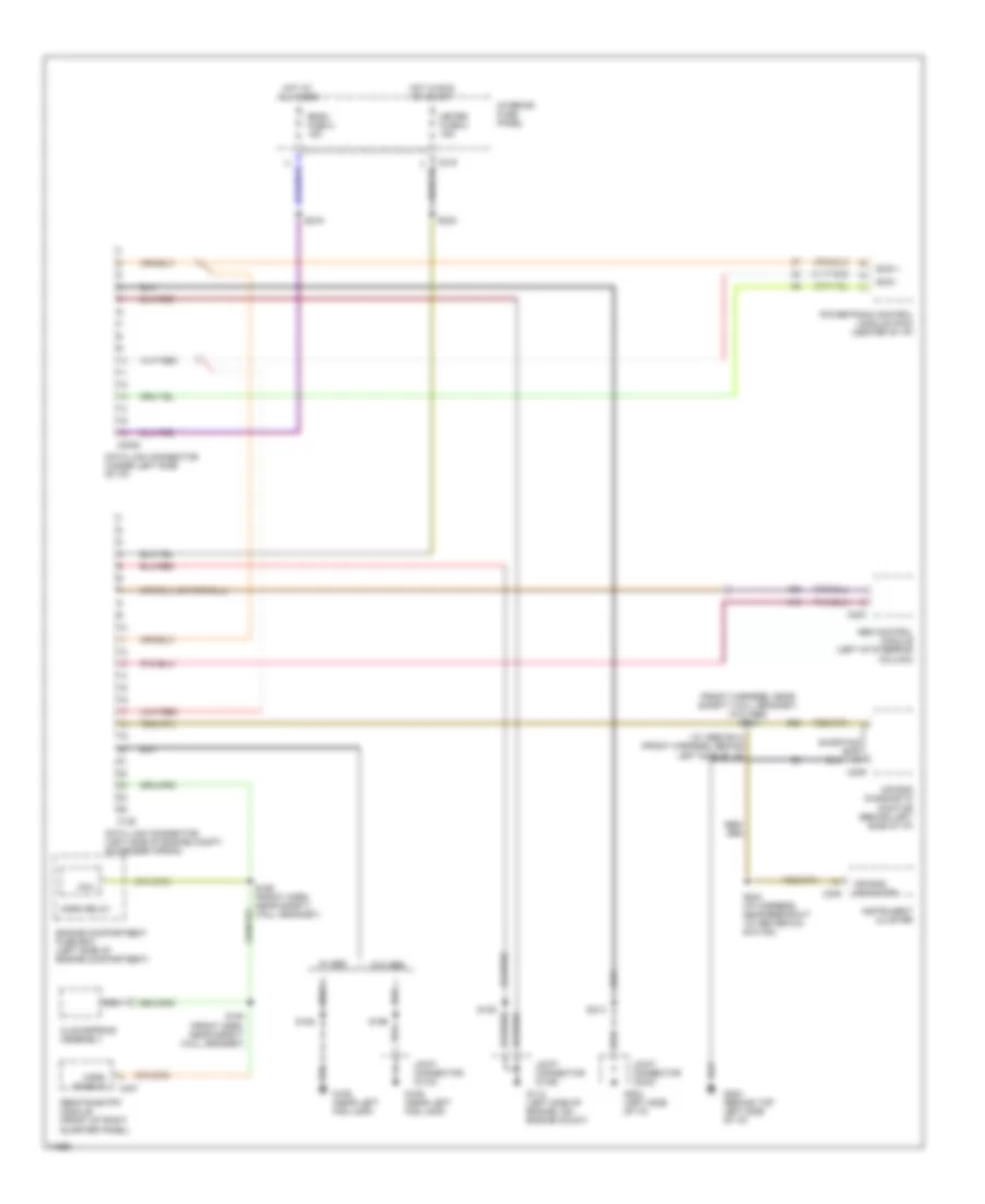
2.0L 2.0L, Computer Data Lines for Ford Probe SE 1996 List of elements for 2.0L, Computer Data Lines for Ford Probe SE 1996: 49 (front harness, near safety wall grommet) (w/o abs) s219 (w/ abs) s214 (front harness, behind left side of i/p) Abs control module (left of steering column) Air bag diagnostic monitor (behind left side of i/p) Air bag indicator Bus + Bus - C135 C2020 C209 C215 C223 C240 C407 Clockspring assembly Coil Data link connector (left side of engine compt, on fender apron) Data link connector (under left side of i/p) Engine compartment fuse box (left side of engine compartment) G106 (near left fog lamp) G112 (left side of engine, on) engine mount) G202 (behind top left side of i/p) G202 (left side of i/p) Horn enable Horn relay Hot at all times Hot in run or start Instrument cluster Interior fuse panel Joint connector (c103) Joint connector (c106) Joint connector (c203) Meter fuse 8 15a Nca Powertrain control module (pcm) (center of i/p) Remote entry module (front of right quarter panel) Room fuse 2 15a S106 S136 S154 (front harn, near safety wall grommet) S155 (front harn, near safety wall grommet) S199 S213 S216 S232 S244 (i/p harness, near breakout to heater-a/c switch) Shorting bar W/ abs W/o abs
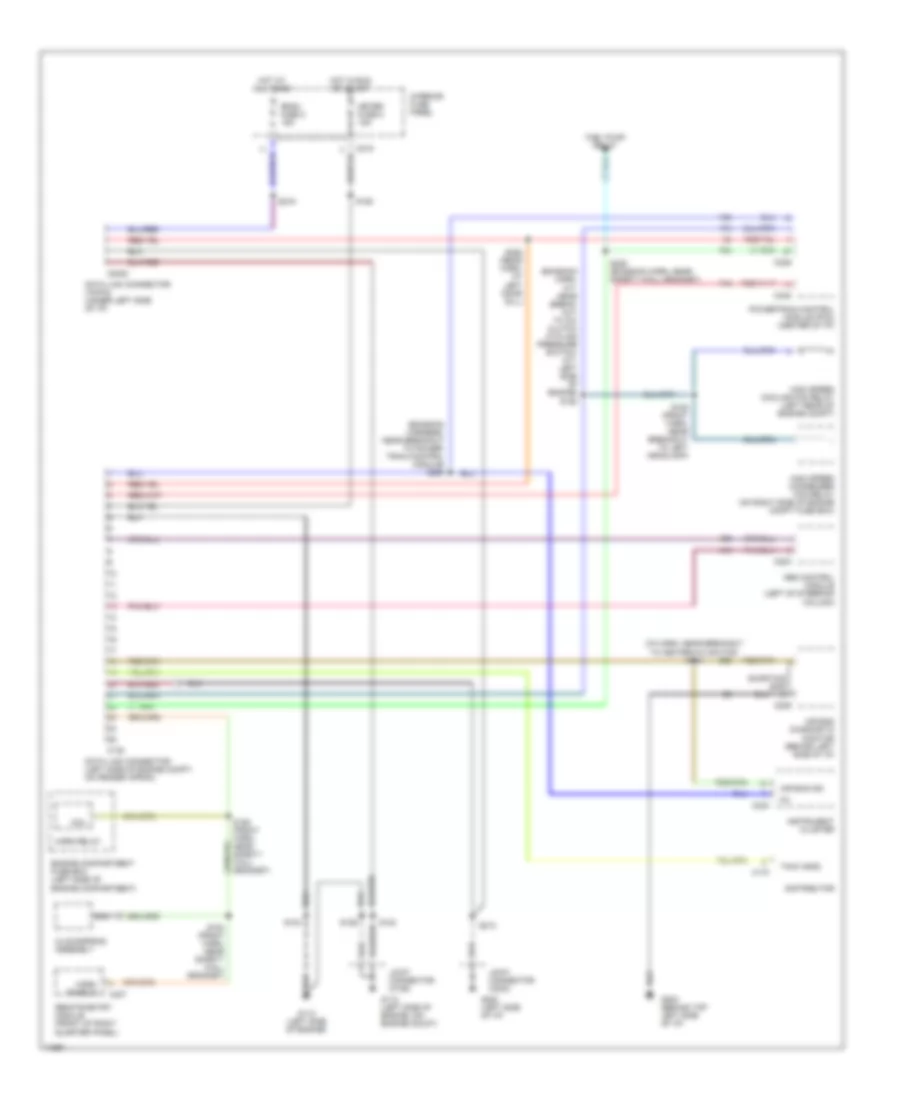
2.5L 2.5L, Computer Data Lines for Ford Probe SE 1996 List of elements for 2.5L, Computer Data Lines for Ford Probe SE 1996: 55 (emission harn, a/t: near break- out to a/c clutch cycling pressure switch; m/t: left side of engine) s192 (emission harness, near breakout to power- train control module) s285 (i/p harn, near breakout to heater-a/c switch) s244 Abs control module (left of steering column) Air bag diagnostic monitor (behind left side of i/p) Air bag ind C135 C170 C2020 C209 C215 C223 C240 C246 C248 C407 Clockspring assembly Coil Data link connector (16-pin) (under left side of i/p) Data link connector (left side of engine compt, on fender apron) Distributor Engine compartment fuse box (left side of engine compartment) Fuel pump relay G112 (left side of engine) G112 (left side of engine, on) engine mount) G202 (behind top left side of i/p) G202 (left side of i/p) High speed condenser fan relay (on right side of engine compt fuse box) High speed cooling fan relay (left rear of engine compt) Horn enable Horn relay Hot at all times Hot in run or start Instrument cluster Interior fuse panel Joint connector (c106) Joint connector (c203) Meter fuse 8 15a Mil Nca Powertrain control module (pcm) (center of i/p) Remote entry module (front of right quarter panel) Room fuse 2 15a S104 S123 S126 S150 S154 (front harn, near safety wall grommet) S188 (front harn, near breakout to left headlamp) S213 S216 S228 (emission harn, near safety wall grommet) S258 (rear harn, at left door sill) Shorting bar Tach (gnd)
COOLING FAN
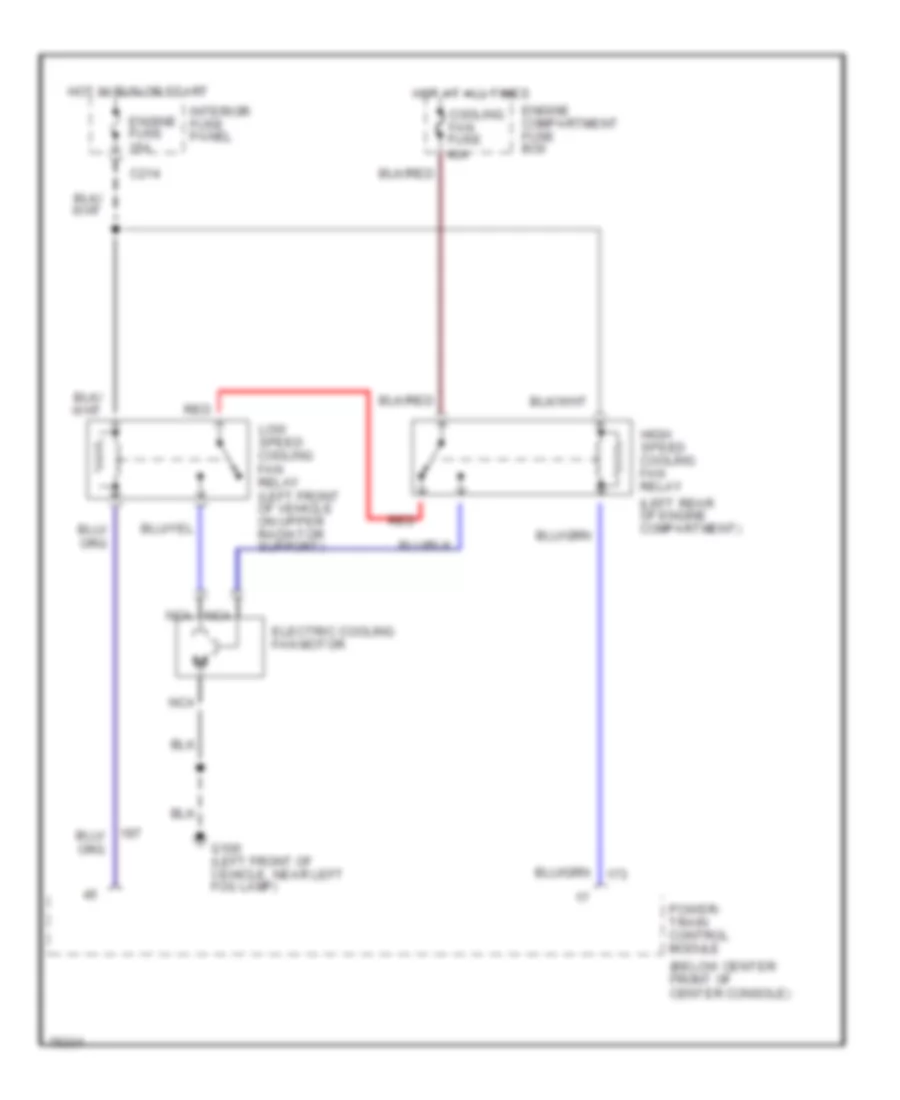
2.0L 2.0L, Cooling Fan Wiring Diagram for Ford Probe SE 1996 List of elements for 2.0L, Cooling Fan Wiring Diagram for Ford Probe SE 1996: 16 (below center front of center console) (left rear of engine compartment) C214 Cooling fan fuse 40a Electric cooling fan motor Engine compartment fuse box Engine fuse 15a G100 (left front of vehicle, near left fog lamp) High speed cooling fan relay Hot at all times Hot in run or start Interior fuse panel Low speed cooling fan relay (left front of vehicle on upper radiator support) Nca Power- train control module Red
2.5L 2.5L, Cooling Fan Wiring Diagram for Ford Probe SE 1996 List of elements for 2.5L, Cooling Fan Wiring Diagram for Ford Probe SE 1996: 22 (below center front of center console) (left rear of engine compartment) Aircond fuse 15a Aircond fuse 40a Condenser fan motor Cooling fan fuse 40a Data link connector (left side of engine compartment) Electric cooling fan motor Engine compartment fuse box Engine fuse 15a G100 (left front of vehicle, near left fog lamp) High speed conden- ser fan relay (on right side of engine compart- ment fuse box) High speed cooling fan relay Hot at all times Hot in accy or run Hot in run or start Interior fuse panel Low speed conden- ser fan relay (on right side of engine compart- ment fuse box) Low speed cooling fan relay (left front of vehicle on upper radiator support) Nca Power- train control module Red
CRUISE CONTROL
2.0L 2.0L, Cruise Control Wiring Diagram, with A/T for Ford Probe SE 1996 List of elements for 2.0L, Cruise Control Wiring Diagram, with A/T for Ford Probe SE 1996: 42 (behind left side of i/p) (lower rear (on brake (w/ abs) (w/o abs) 15a 20a Accel Air cond Assembly Brake on/off Brake release in C214 C216 C227 Clockspring Coast Control sw in Control sw rtn Fuse Hot at all times Hot in run Ign Interior Nca Of transaxle) Off Ohms Panel Pedal Resume Sensor Set/ Speed Speed control Speed control module Stop Support) Switch Switch assembly Vehicle Vss 2.0L, Cruise Control Wiring Diagram, with M/T for Ford Probe SE 1996 List of elements for 2.0L, Cruise Control Wiring Diagram, with M/T for Ford Probe SE 1996: 62 (behind left side of i/p) (boo) switch (c103) (left center of (left front of vehicle, (lower rear (on brake (on clutch 15a 20a Accel Air cond Assembly Brake on/off Brake/clutch sw in C214 C216 C227 C228 Clockspring Clutch pedal Coast Connector Control sw in Engine compt.) Fuse G106 Gnd Hot at all times Hot in run Ignition Input Interior Joint Nca Near fog lamp) Of transaxle) Off Ohms Panel Pedal Pedal support) Position Position switch Resume Sensor Servo Set/ Sol feed Speed Speed control Speed control module Speed control servo Stop Support) Switch assembly Vac Vacuum sol control Vehicle Vent Vent sol control Vss
2.5L 2.5L, Cruise Control Wiring Diagram for Ford Probe SE 1996 List of elements for 2.5L, Cruise Control Wiring Diagram for Ford Probe SE 1996: 77 (behind left side of i/p) (boo) switch (c103) (front (left center of (left front of vehicle, near fog lamp) (lower rear (on brake (on clutch 15a 20a A/t Accel Air cond Assembly Behind left Brake on/off Brake/clutch sw in C214 C216 C227 C228 Clockspring Clutch pedal Coast Connector Control sw in Engine compt) Fuse G106 Gnd Harness, Hot at all times Hot in run Ignition Input Interior Joint M/t Nca Near Of transaxle) Off Ohms Panel Pedal Pedal support) Position Position switch Resume S111 S134 S135 S204 S225 S251 S282 Safety Sensor Servo Set/ Side of i/p) Sol feed Speed Speed control Speed control module Speed control servo Stop Support) Switch assembly Vac Vacuum sol control Vehicle Vent Vent sol control Vss Wall grommet)
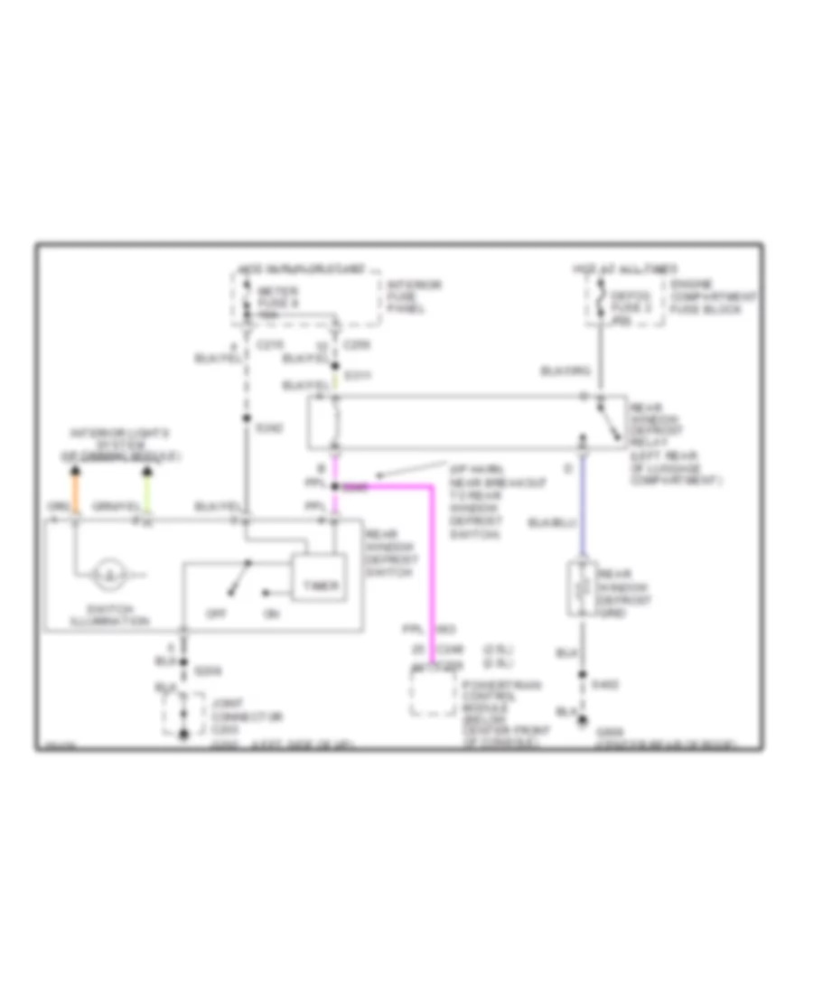
DEFOGGERS Defogger Wiring Diagram for Ford Probe SE 1996 List of elements for Defogger Wiring Diagram for Ford Probe SE 1996: 28 (2.5l) (2.0l) (i/p harn, near breakout to rear window defrost switch) (left side of i/p) C215 C248 C256 Defog fuse 2 40a Engine compartment fuse block G202 G909 (center rear of roof) Hot at all times Hot in run or start Interior fuse panel Interior lights system (i/p dimming module) Joint connector c203 Meter fuse 8 10a Off Powertrain control module (below center front of console) Rear window defrost grid Rear window defrost relay (left rear of luggage compartment) Rear window defrost switch S208 S242 S245 S311 S402 Switch illumination Timer
ENGINE PERFORMANCE
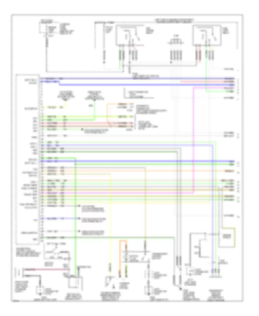
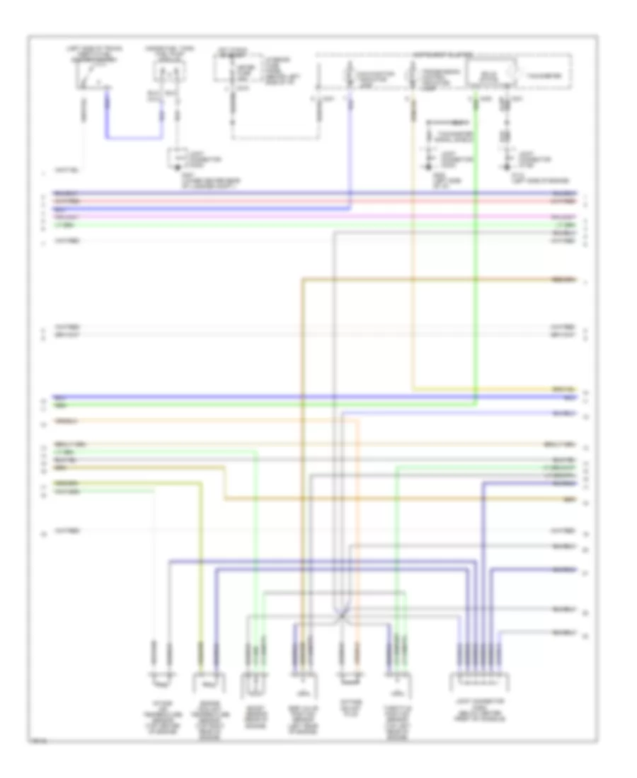
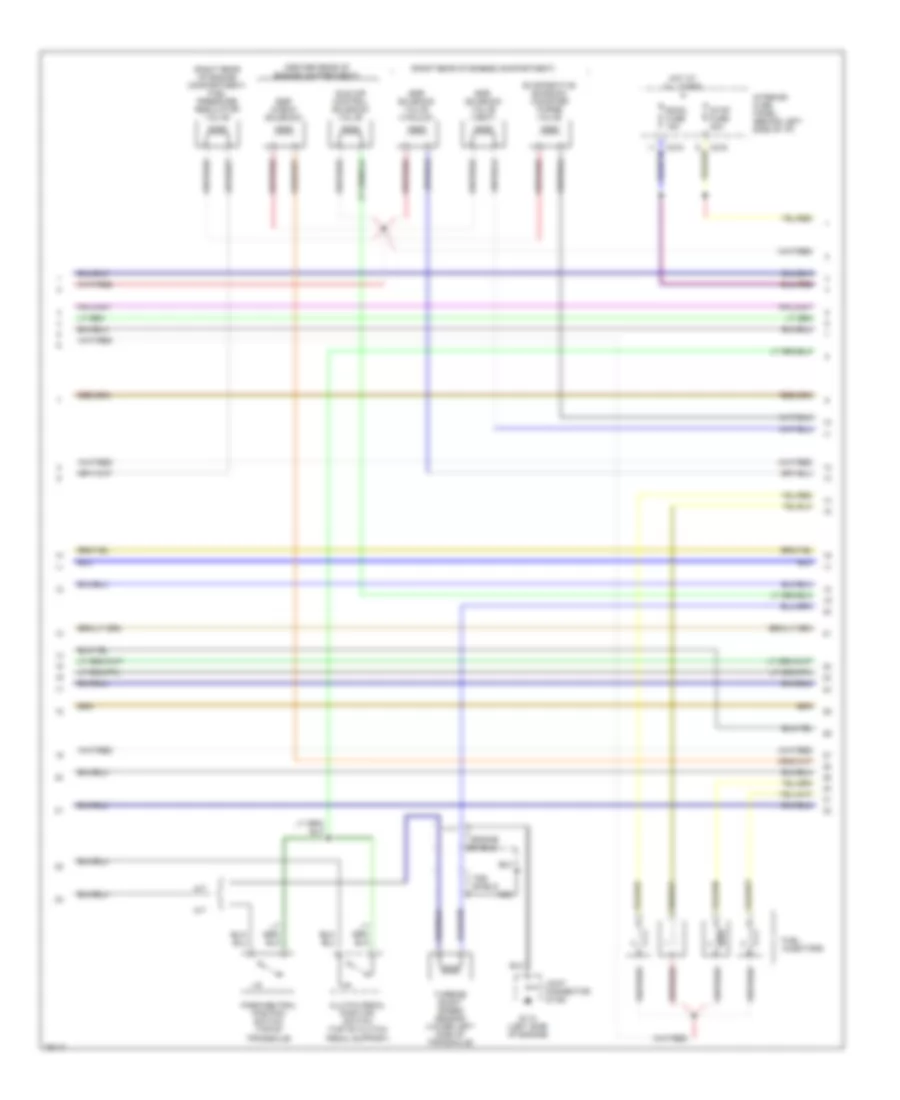
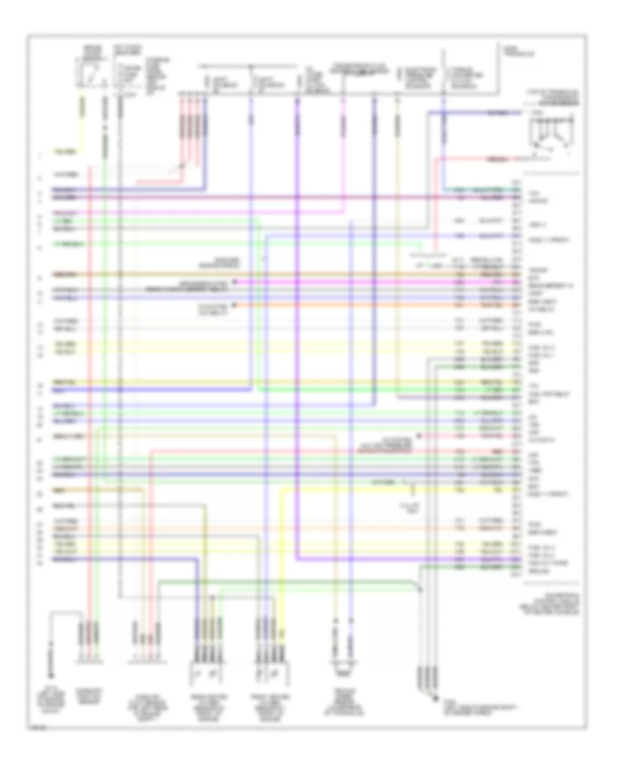
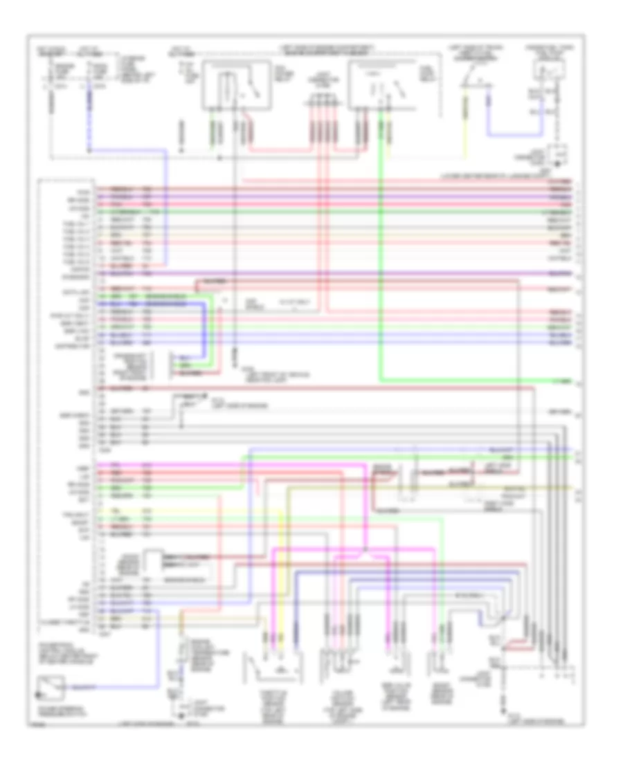
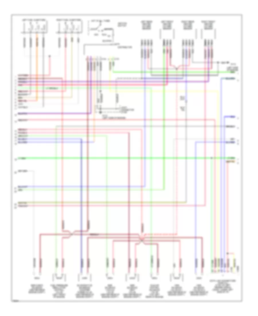
2.0L 2.0L, Engine Performance Wiring Diagrams (1 of 4) for Ford Probe SE 1996 List of elements for 2.0L, Engine Performance Wiring Diagrams (1 of 4) for Ford Probe SE 1996: 75 (c103) 2.0l w/o abs (left side of engine compartment) engine compartment fuse box (near left fog lamp) * g106 (left front of vehicle, near fog lamp) * joint connector A/c clutch A/c system (a/c high pressure cutout/fan switch) A/c system (high speed blower motor relay) Acc Blower on Boost sens C135 C169 C2020 C214 Ckp (+) Ckp (-) Ckp shield Cooling fans system (high speed relay) Crankshaft position sensor (lower right side of engine) Data link connector (under left side of i/p) Diagnostic connector (left side of engine compt., on fender apron) Distributor Dlc Drl Ect Engine fuse 15a Engine shield F/p inj fuse 30a Fprc Fuel pmp relay Fuel pump relay G100 (left side of engine compt., on fender apron) G106 G112 (left side of engine) G202 (left side of i/p) Gnd Headlamps on Headlights system (drl relay & control module) Headlights system (headlights relay) Hfc Ho2s 12 (rear) Hot at all times Hot in run or start Iat Ig1 Ign coil Ignition coil (left front of engine compt.) Ignition switch Interior fuse panel (behind left side of i/p) Interior lights system Joint connector (c103) Joint connector (c106) Joint connector (c203) Joint connector (c234) Lfc Lock Maf Nca Octane plug Pcm power relay Power steering pressure switch (right front of engine compt.) Powertrain control module (below center front of center console) Psp sw Radio noise capacitor (left front of engine compt.) Run Shift sol 1 Shift sol 2 Start Sto/mil Switch illum- ination Tcs Trans temp Transmission control switch Vss (-) 2.0L, Engine Performance Wiring Diagrams (2 of 4) for Ford Probe SE 1996 List of elements for 2.0L, Engine Performance Wiring Diagrams (2 of 4) for Ford Probe SE 1996: 25 (inside fuel tank) fuel pump module (left side of trunk) inertia fuel shutoff switch Boost sensor (rear of engine) C215 Egr valve position sensor (left rear of engine) Engine coolant temperature sensor (top right rear of engine) G112 (left side of engine) G202 (left side of i/p) G407 (lower center rear of luggage compt.) Hot in run or start Instrument cluster Intake air temperature sensor (top center of engine) Interior fuse panel (behind left side of i/p) Joint connector (c106) Joint connector (c203) Joint connector (c264) (below center front of console) Joint connector (c400) Malfunction indicator lamp Meter fuse 15a Octane adjust plug Solid state Tachometer Tachometer signal shield Throttle position sensor (top left rear of engine) Transmission control indicator lamp 2.0L, Engine Performance Wiring Diagrams (3 of 4) for Ford Probe SE 1996 List of elements for 2.0L, Engine Performance Wiring Diagrams (3 of 4) for Ford Probe SE 1996: 23 (center rear of engine compartment) (right rear of engine compartment) (right rear of engine compartment) fuel pressure regulator valve A/t Clutch pedal position switch (top of clutch pedal support) Egr check solenoid Egr solenoid valve (vacuum) Egr solenoid valve (vent) Engine shield Evaporative emission canister purge valve Fuel injectors G112 (left side of engine) Hot at all times Idle air control solenoid valve Interior fuse panel (behind left side of i/p) Joint connector (c106) M/t Nca Park/neutral position switch (top of transaxle) Room fuse 15a Stop fuse 20a Tss shield Turbine shaft speed sensor (lower left side of transaxle) 2.0L, Engine Performance Wiring Diagrams (4 of 4) for Ford Probe SE 1996 List of elements for 2.0L, Engine Performance Wiring Diagrams (4 of 4) for Ford Probe SE 1996: 62 (817) (top of transaxle) transmission range sensor 2.0l a/t only 3-2 timing/ coast clutch solenoid A/c fan in A/c relay A/c system (a/c high pressure cutout/fan switch) A/c system (a/c relay) A/t Boo Brake on/off switch Camshaft position sensor Canp Ccs (3-2 timing) Cd4e transaxle Cmp Defogger system (rear window defrost relay) Egr (vac) Egr (vent) Egr check Electronic pressure control solenoid Epc Evp Front heated oxygen sensor #11 (front of engine) Fuel inj 1 Fuel inj 2 Fuel inj 3 Fuel inj 4 Fuel pmp relay G100 (left side of engine compt., on fender apron) G112 (left side of engine, on engine mount) Gnd Ground Ho2s 11 (front) Hot in run or start Iac Interior fuse panel (behind left side of i/p) Kapwr M/t Maf Mass air flow sensor (top left rear of engine compt.) Meter fuse 20a Nca Powertrain control module (below center front of center console) Pwr Rear defrost in Rear heated oxygen sensor #12 (front of engine) Red Rtn Shielded (engine shield) Shift solenoid #1 Shift solenoid #2 Tcc Tcil Torque converter clutch solenoid Tps Tr/pnp Transmission fluid temperature sensor Tss Vehicle speed sensor (lower rear of transaxle) Vref Vss (+)
2.5L 2.5L, Engine Performance Wiring Diagrams (1 of 3) for Ford Probe SE 1996 List of elements for 2.5L, Engine Performance Wiring Diagrams (1 of 3) for Ford Probe SE 1996: 73 (engine shield) (inside fuel tank) fuel pump module (left front of vehicle, near fog lamp) (left side of engine compartment) engine compartment fuse box (left side of engine) (left side of trunk) inertia fuel shutoff switch Boost Boost sensor (rear of engine) C214 C215 C247 C248 Ckp Ckp shield Closed throttle Crankshaft position sensor (right front of engine) Data link Diagnosis Distributor Ect Egr (vac) Egr (vent) Egr check Egr valve position sensor (left rear of engine) Engine coolant temperature sensor (rear of engine) Engine fuse 15a Engine shield Evap Evp F/p inj fuse 30a Fuel inj 1 Fuel inj 2 Fuel inj 3 Fuel inj 4 Fuel inj 5 Fuel inj 6 Fuel pump relay G106 G112 G112 (left side of engine) G407 (lower center rear of luggage compt.) Gnd Hot at all times Hot in run or start Iac Interior fuse panel (behind left side of i/p) Joint connector (c106) Joint connector (c169) Joint connector (c400) Kapwr Knock sensor (rear of engine) Left ho2s shield Lf ho2s Lr ho2s Nca Pcm power relay Pnk Power steering pressure switch Powertrain control module (below center front of center console) Psp Pwr Pwr (a/t only) Red Rf ho2s Right ho2s shield Room fuse 15a Rr ho2s Throttle position sensor (top left rear of engine) Tps input Vaf Volume air flow sensor (top left side of engine compt.) Vref W/ a/t only 2.5L, Engine Performance Wiring Diagrams (2 of 3) for Ford Probe SE 1996 List of elements for 2.5L, Engine Performance Wiring Diagrams (2 of 3) for Ford Probe SE 1996: 33 (left side of engine) Acc C134 C135 C170 C2020 Data link connectors (partial) (c135: on left fender apron) (c2020: under left side of i/p) Distributor Egr check solenoid (center rear engine compt.) Egr solenoid vacuum valve (center rear of engine compt.) Egr solenoid vent valve (center rear of engine compt.) Evaporative emissions canister purge valve (center rear of engine compt.) Fuel pressure regulator control valve (left front of engine) G112 G112 (left side of engine) Hot at all times Idle air control solenoid valve (top left rear of engine) Ig1 Ignition switch Joint connector (c106) Left front heated oxygen sensor Left fuel injectors Left rear heated oxygen sensor Lock Nca Pnk Right front heated oxygen sensor Right fuel injectors Right rear heated oxygen sensor Run Start Vris solenoid valve no.1 (center rear of engine compt.) Vris solenoid valve no.2 (center rear of engine compt.) 2.5L, Engine Performance Wiring Diagrams (3 of 3) for Ford Probe SE 1996 List of elements for 2.5L, Engine Performance Wiring Diagrams (3 of 3) for Ford Probe SE 1996: 88 (w/ a/t only) 1-2 shift sol 1-2 shift solenoid 2-3 shift sol 2-3 shift solenoid 3-4 shift sol 3-4 shift solenoid 4eat transaxle A/c high pressure cutout/fan switch A/c press (clutch) A/c press (fan) A/c relay Acc Acon Backup lamps Blower assembly (high speed blower motor relay) & blower motor switch) Blower on Boo input Brake on/off switch C215 C216 C245 C246 Data link Defrost on Downshift timing solenoid Drl module & drl relay Drl on input Dwnshft timing sol Fprc Fuel pump relay G202 (left side of engine) G202 (left side of i/p) Head lamp switch, headlamp relay & central processing unit) Headlamps on Hfc High speed cooling fan relay & high speed condenser fan relay Hot at all times Hot in run or start Ignition switch Instrument cluster Interior fuse panel (behind left side of i/p) Joint con- nector (c234) Joint connector (c106) Joint connector (c203) Joint connector (c234) Lfc Line press sol Line pressure solenoid Lock Low speed condenser fan relay Low speed cooling fan relay Malfunction indicator lamp Meter fuse 15a Mil Powertrain control module (below center front of center console) Rear window defrost switch & relay Red Run Speedo Start Start input Starting sig Starting system Stop fuse 20a Tach Tachometer signal shield Tcc sol Tcil Tcs Tft Torq conv on/off Torque converter control solenoid Torque converter on/off solenoid Tr-1 Tr-2 Tr-d Tr-r Transaxle fluid temperature sensor Transmission control indicator lamp Transmission control switch Transmission range sensor (lower front of transaxle) Tss (+) Tss (-) Turbine shaft speed sensor (lower rear of transaxle) Vris no.1 Vris no.2 Vss (+)
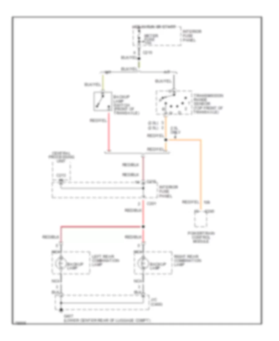
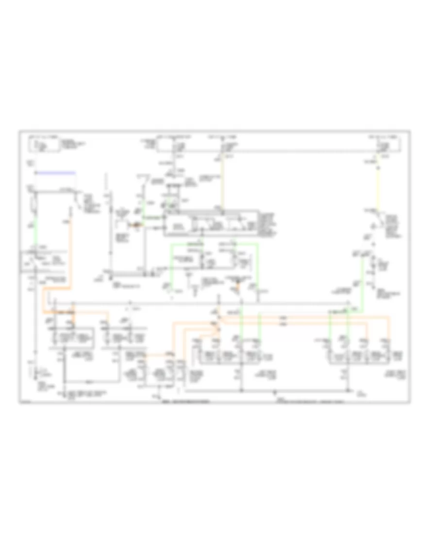
EXTERIOR LIGHTS Back-up Lamps Wiring Diagram for Ford Probe SE 1996 List of elements for Back-up Lamps Wiring Diagram for Ford Probe SE 1996: 22 (2.0l) (2.5l) 2.5l only A/t Backup lamp Backup lamp switch (front of transaxle) C201 C213 C215 C245 Central processing unit G407 (lower center rear of luggage compt) Hot in run or start Interior fuse panel J/c (c400) Left rear combination lamp M/t Meter fuse 15a Nca Powertrain control module Right rear combination lamp Transmission range sensor (top front of transaxle) Exterior Lamps Wiring Diagram for Ford Probe SE 1996 List of elements for Exterior Lamps Wiring Diagram for Ford Probe SE 1996: 65 (c203) (center rear of roof) (left front of vehicle, near left fog lamp) g100 Brake on/off switch (top of brake pedal support) C201 C207 C213 C214 C215 C216 C225 C240 C241 Center license plate lamp Central processing unit Combination switch Engine compartment fuse box Flasher module (behind left side of i/p, left of steering column) Front marker lamp Front turn lamp G202 (left side of i/p) G204 (left side of i/p) G407 (lower center rear of luggage compt) G909 G909 (center rear of roof) Hazard fuse 15a Hazard switch Head Hi mount stop lamp Hot at all times Hot in run or start Instrument cluster Interior fuse panel Interior lights system J/c J/c (c203) J/c (c400) Left Left front combination lamp Left license plate lamp Left rear combination lamp Left turn ind. Left turn relay Main lamp switch Nca Off Park Park lamp relay (in engine compt fuse box) Rear marker lamp Rear park lamp Rear turn lamp Remote entry module Right Right front combination lamp Right license plate lamp Right rear combination lamp Right turn ind. Right turn relay Solid state Stop fuse 20a Stop lamp Tail fuse 15a Turn fuse 15a Turn signal switch W/ keyless entry
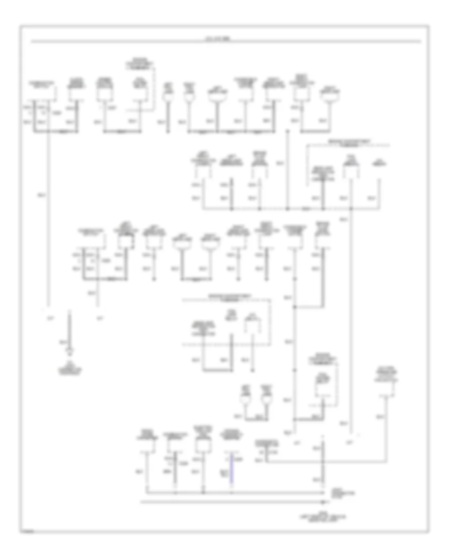
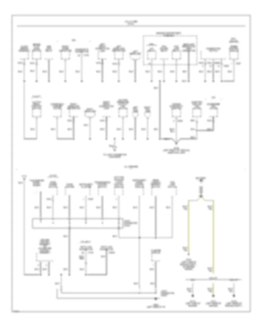
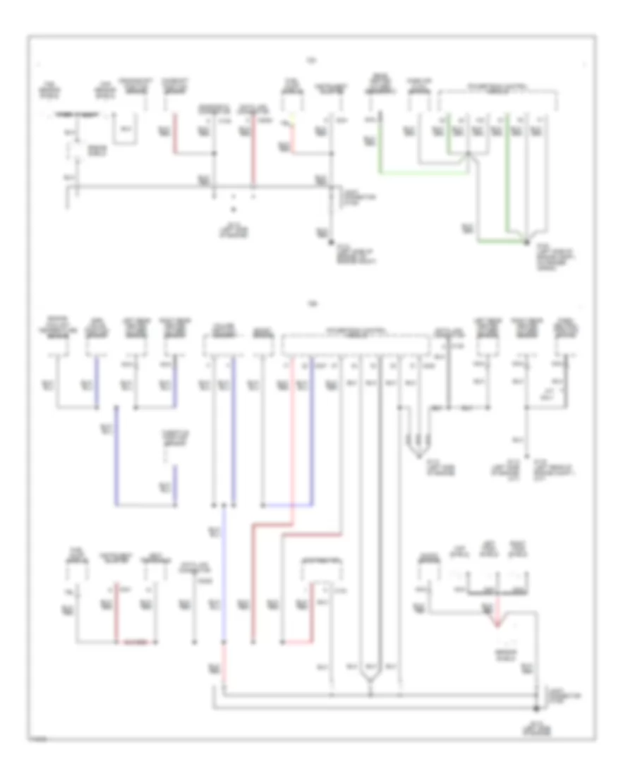
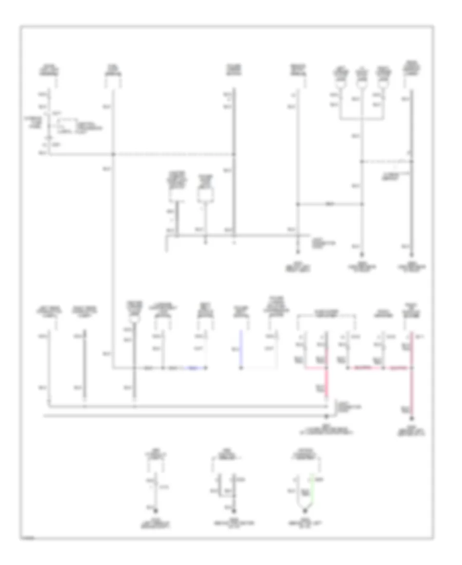
GROUND DISTRIBUTION Ground Distribution Wiring Diagram (1 of 4) for Ford Probe SE 1996 List of elements for Ground Distribution Wiring Diagram (1 of 4) for Ford Probe SE 1996: 34 2.0l w/o abs A/c high pressure cutout/ fan switch A/c relay A/t Air bag diagnostic monitor Brake fluid level switch C135 C209 C225 C227 Clock- spring assembly Combination switch Diagnostic connector Electric cooling fan motor Engine compartment fuse box Fog lamp relay G106 (left front of vehicle, near fog lamp) Headlamp retractor test connector Joint connector (c103) Left fog lamp Left front combination lamp Left headlamp Left headlamp retractor M/t Nca Pcm power relay Radio noise capacitor Right fog lamp Right front combination lamp Right headlamp Right headlamp retractor Speed control module To joint connector (c203/g202) Windshield washer motor Ground Distribution Wiring Diagram (2 of 4) for Ford Probe SE 1996 List of elements for Ground Distribution Wiring Diagram (2 of 4) for Ford Probe SE 1996: 64 2.0l 2.0l w/ abs & 2.5l 2.5l 2.5l a/t 2.5l m/t 2.5l only A/c high pressure cutout/ fan switch A/c relay Abs main relay Air bag diagnostic monitor All engines Battery Brake fluid level switch C135 C2020 C209 C225 C227 C240 Cigar lighter Clock spring assembly Clutch pedal position switch Combination switch Condenser fan motor Data link connector Daytime running lamps control module Diagnostic connector Electric cooling fan motor Engine compartment fuse box Exc. 2.0l a/t Flasher module Fog lamp relay Fog lamp switch G100 (left side of engine compt., on fender apron) G106 (left front of vehicle, near fog lamp) G112 (left side of engine) G114 (left rear of engine) G116 (left rear of engine compt.) G202 (left side of i/p) Headlamp retractor test connector Heater control assembly or a/c-heater control assembly Instrument cluster Instrument panel dimming module Joint connector (c203) Joint connector (c234) Left fog lamp Left front combination lamp Left headlamp Left headlamp retractor Nca Park range switch Pcm power relay Radio noise capacitor Rear window defrost switch Right fog lamp Right front combination lamp Right headlamp Right headlamp retractor Speed control module Tachometer signal shield To joint connector (c203/g202) Transmission control switch W/ a/t Windshield washer motor Ground Distribution Wiring Diagram (3 of 4) for Ford Probe SE 1996 List of elements for Ground Distribution Wiring Diagram (3 of 4) for Ford Probe SE 1996: 43 2.0l 2.5l 4eat transaxle Boost sensor C134 C135 C2020 C241 C247 C248 Camshaft position sensor Ckp sensor shield Ckp shield Crankshaft position sensor Data link connector Diagnostic connector Distributor Egr valve position sensor Engine coolant temperature sensor Engine shield Fuel pump module G100 (left side of engine compt., on fender apron) G112 (left side of engine) G112 (left side of engine) (a/t) G112 (left side of engine, on engine mount) G116 (left rear of engine compt.) (m/t) Instrument cluster Joint connector (c106) Knock sensor Left ho2s shield Left rear heated oxygen sensor M/t only Mass air flow sensor Nca Park/ neutral position switch Powertrain control module Rear heated oxygen sensor #12 Right ho2s shield Right rear heated oxygen sensor Sensor shield Throttle position sensor Tss sensor shield Volume air flow sensor Ground Distribution Wiring Diagram (4 of 4) for Ford Probe SE 1996 List of elements for Ground Distribution Wiring Diagram (4 of 4) for Ford Probe SE 1996: 45 Abs control module Abs hydraulic unit Air bag diagnostic monitor C173 C201 C209 C211 C213 C217 C222 C315 C318 Center license plate lamp Central processing unit Dome/ map lamp assembly Fuel pump module G102 (left rear of engine compt.) G202 (behind top left of i/p) G206 (behind left center of i/p) G206 (behind top center of i/p) G300 (below left front seat) G407 (lower center rear of luggage compartment) G909 (center rear of roof) Hi mount stop lamp Interior fuse panel Joint connector (c300) Joint connector (c400) Left license plate lamp Left rear combination lamp Luggage compartment lamp switch Master window/ door lock control switch Nca Power door lock relay Power lumbar/ bolster compressor motor Power mirror switch Power seat switch Radio amplifier Radio or radio/cd player Rear window defrost grid Remote entry module Right license plate lamp Right rear combination lamp Seat belt buckle switch Subwoofer amplifier W/ rear defrost
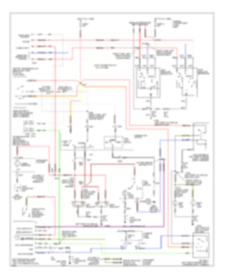
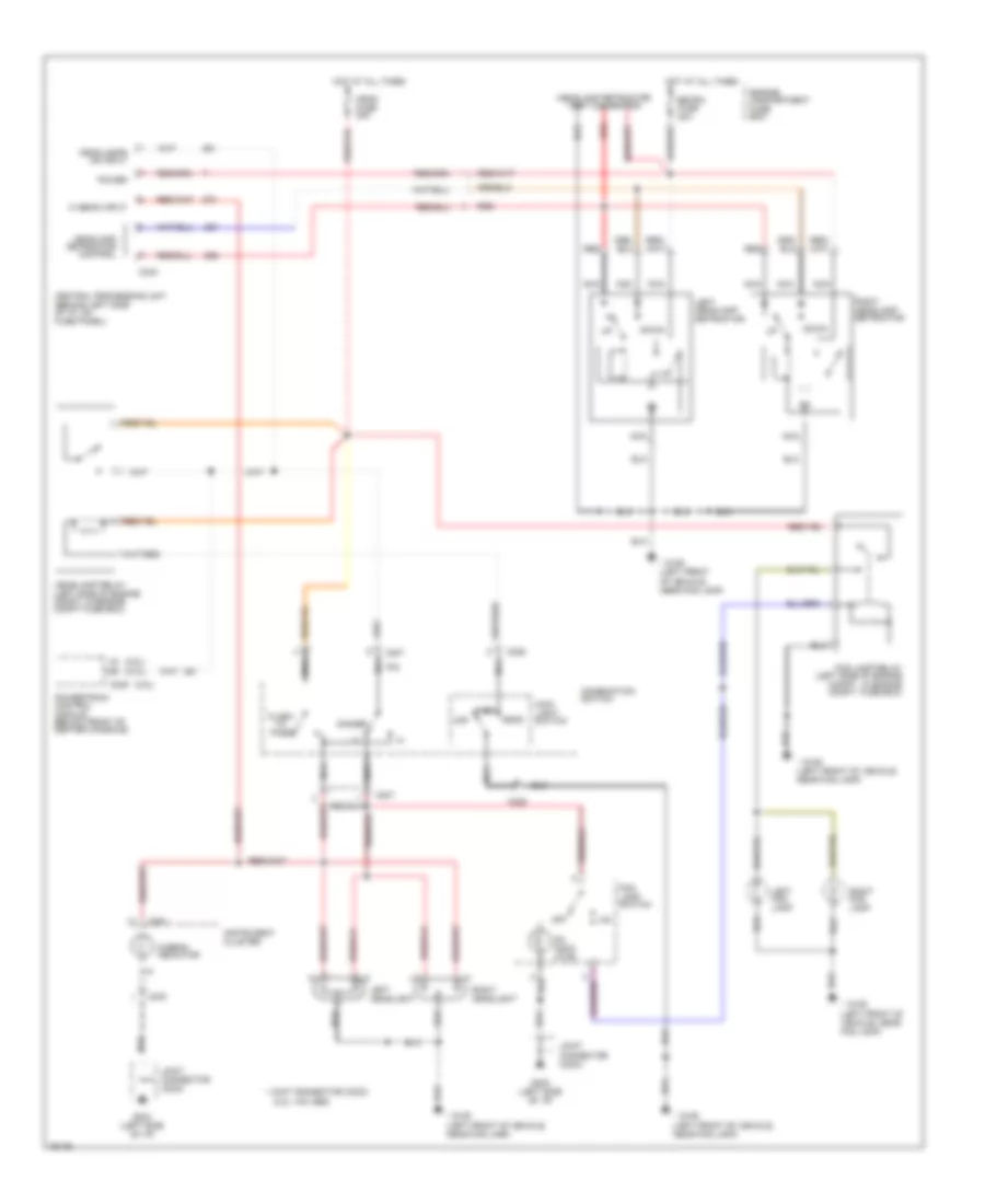
HEADLIGHTS Headlight Wiring Diagram, with DRL for Ford Probe SE 1996 List of elements for Headlight Wiring Diagram, with DRL for Ford Probe SE 1996: 102 (2.0l w/o abs) (2.0l) (2.5l) (2.ol) (emission harn, near saftey wall grommet) (eng harn, in pcm breakout) s277 (front harn, in eng compt fuse box breakout) (front harn, left rear of engine compartment) (i/p harn, behind center of i/p) (i/p harn, behind left side of i/p) s276 (i/p harn, in instrument cluster breakout) (left front of vehicle, near fog lamp) (left side of i/p) (left side of i/p) g202 * g106 * g106 (left front of vehicle, near fog lamp) * joint connector c103 Brake fluid level switch Brake indicator C204 C207 C214 C215 C225 C240 C241 C246 C256 Central processing unit (behind left side of i/p, on fuse panel) Combination switch Daytime running lamps (drl) control module (left of steering column) Dimmer Down Drl disable Drl relay (left side of engine compt., in engine compt. fuse box) Engine compartment fuse box Flash Fog lamp relay (left side of engine compt, in engine compt fuse box) Fog lamp switch Fog lamps enable Fog lamps on in Fuse 1 30a Fuse 12 15a Fuse 12 20a G202 G202 (behind left side of i/p) G202 (left side of i/p) Gnd Head Headlamp relay (left side of engine compt, in engine compt fuse box) Headlamp retractor control Headlamp retractor test connector Headlamps on in Headlamps on input Hi beam indicator Hi beam input Hot at all times Hot in acc or run Ignition power Instrument cluster Instrument cluster system Interior fuse panel J/c c234 Joint connector c203 Left fog lamp Left headlamp retractor Left headlight Main light switch Nca Off On indic- ator Park Park switch switch (on top of park brake support) Power Powertrain control module (pcm) (below front of center console) Red Right fog lamp Right headlamp retractor Right headlight S100 S105 or s106 S106 or s109 S107 or s118 S107 or s119 S109 S130 S151 S166 (front harn, left rear of engine compartment) S168 (front harn, left rear of eng compt) S170 (front harn, near saftey wall grommet) S171 S172 (front harn, left front of eng compt) S174 S175 S197 S208 S260 S273 S274 S275 To pass Headlight Wiring Diagram, without DRL for Ford Probe SE 1996 List of elements for Headlight Wiring Diagram, without DRL for Ford Probe SE 1996: 48 (2.0l w/o abs) (2.5l) (2.ol) (left front of vehicle, near fog lamp) * g106 * joint connector (c203) C207 C225 C240 C241 C246 Central processing unit (behind left side of i/p, on fuse panel) Combination switch Dimmer Down Engine compartment fuse box Flash Fog lamp relay (left side of engine compt., in engine compt. fuse box) Fog lamp switch G202 (left side of i/p) Head Head fuse 30a Headlamp relay (left side of engine compt, in engine compt fuse box) Headlamp retractor control Headlamp retractor test connector Headlamps on input Hi beam indicator Hi beam input Hot at all times Instrument cluster Joint connector (c203) Left fog lamp Left headlamp retractor Left headlight Main light switch Nca Off On indic- ator Park Power Powertrain control module (below front of center console) Red Retra fuse 20a Right fog lamp Right headlamp retractor Right headlight To pass
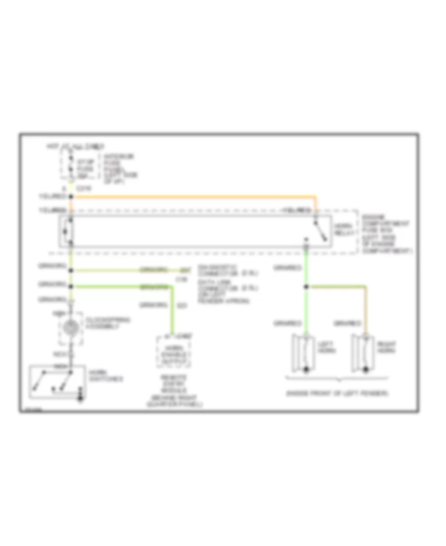
HORN Horn Wiring Diagram for Ford Probe SE 1996 List of elements for Horn Wiring Diagram for Ford Probe SE 1996: 21 (2.0l) (2.5l) (inside front of left fender) C135 C216 C407 Clockspring assembly Data link connector (on left fender apron) Diagnostic connector Engine compartment fuse box (left side of engine compartment) Horn enable output Horn relay Horn switches Hot at all times Interior fuse panel (left side of i/p) Left horn Nca nca Remote entry module (behind right quarter panel) Right horn Stop fuse 20a
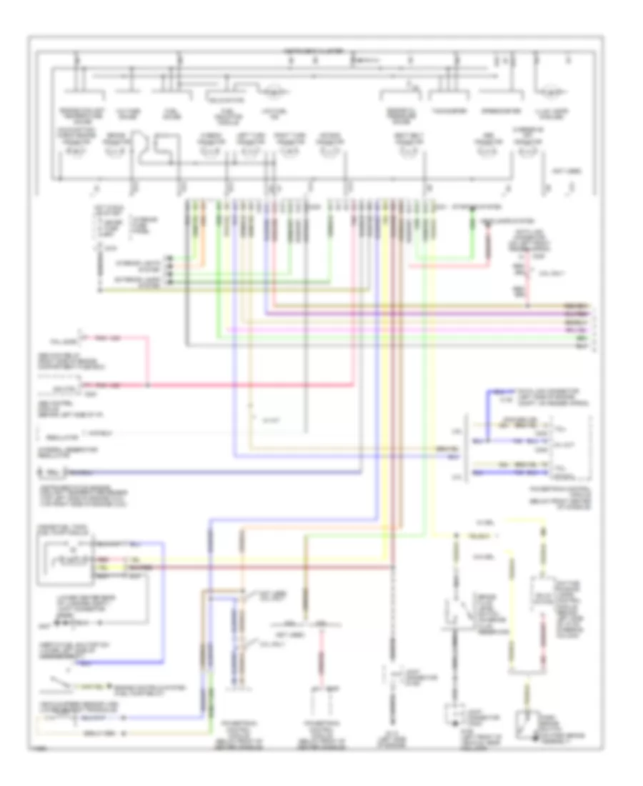
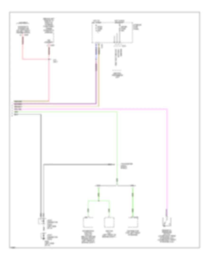
INSTRUMENT CLUSTER Instrument Cluster Wiring Diagram (1 of 2) for Ford Probe SE 1996 List of elements for Instrument Cluster Wiring Diagram (1 of 2) for Ford Probe SE 1996: 86 (inside fuel tank) fuel pump module (lower center rear of luggage compt.) joint connector (c400) (not used) 2.0l 2.0l only 2.5l 2.5l only A10 A11 A12 A13 A14 A15 A16 A16 c240 Abs control module (behind left side of i/p) Abs indicator Abs main relay (right side of engine compartment fuse box) Air bag indicator B10 B11 B12 B13 B14 B14 c241 Brake fluid level switch (on brake fluid reservoir) Brake indicator C135 C215 C223 C235 C245 C246 Data link connector (left side of engine compt, on fender apron) Data link connector (on left front fender apron) Daytime running lamps control module (behind left side of i/p on steering column) Engine controls system (fuel pump relay) Engine coolant temperature gauge Engine oil pressure gauge Exterior lamps system Fail safe Fuel gauge Fuel indicator module G106 (left front of vehicle, near fog lamp) G112 (left side of engine) G407 Headlamps system Hi-beam indicator Hot in run or start Illum lamps (5 bulbs) Ind ctrl Inertia fuel shutoff sw (lower left side of luggage compt) Instrument cluster Instrumentation engine coolant temperature sensor (top left side of engine) (2.0l) (top right side of engine) (2.5l) Integral generator/ regulator Interior fuse panel Interior lights system Joint connector (c106) Joint connector (c203) Left turn indicator Low fuel ind Malfunction/ check engine indicator Meter fuse 15a Mil out Nca Not used 2.5l only Overdrive off indicator Park brake switch (on park brake assembly) Pnk Powertrain control module (below front center of console) Powertrain control module (below front of center console) Red Regulator Right turn indicator Seat belt indicator Solid state Speedometer Starting system Sto/mil Tachometer Tcil Vehicle speed sensor (vss) (lower rear of transaxle) Voltage gauge W/ a/t W/ drl W/o drl Instrument Cluster Wiring Diagram (2 of 2) for Ford Probe SE 1996 List of elements for Instrument Cluster Wiring Diagram (2 of 2) for Ford Probe SE 1996: 28 (behind left side of i/p right of interior fuse panel) airbag diagnostic module 2.0l 2.0l only 2.5l Battery C170 C209 C213 C215 C235 Central processing unit Diagnostic connector (on left front fender apron) Distributor (top left front of engine) Engine oil pressure switch (lower right rear of engine) 2.0l) (lower right front of engine) (2.5l) G202 (left side of i/p) Hot at all times Hot in run or start Ignition Ignition coil (left front of engine compt.) Ind output Interior fuse panel Joint connector (c203) Joint connector (c234) (left side of i/p) Meter fuse 15a Powertrain control module (below center engine compt) (left rear of engine compt) Room fuse 15a Seat belt ind out Tachometer signal shield
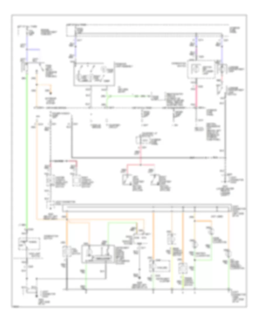
INTERIOR LIGHTS Interior Light Wiring Diagram for Ford Probe SE 1996 List of elements for Interior Light Wiring Diagram for Ford Probe SE 1996: 71 (5 bulbs) (not used) A/c- heater control assembly illumination Bat C201 C211 C213 C214 C215 C217 C225 C240 C400 Central processing unit (behind left side of i/p, on rear of interior fuse panel) Cigar lighter illumination Combination switch Courtesy lp switch in Courtesy lps out Dome lamp Dome/map lamp assembly Door Engine compartment fuse box Exterior lights system Fog lamp switch G204 (left side of i/p) G206 (behind left center of i/p) G300 (below left front seat) G407 (lower center rear of luggage compt.) Gnd Head Hot at all times Hot in acc or run Hot in run or start Ign Ignition key cylinder lamp Instrument cluster Instrument panel dimming module (behind i/p, left of steering column) Interior fuse panel Joint connector (c203) Joint connector (c269) (left side of i/p) Joint connector (c270) (left side of i/p) Joint connector (c300) Joint connector (c400) Key cyl lps out Left door courtesy lamp switch (on left b pillar) Left map lamp Luggage compartment lamp Luggage compartment lamp switch Main lamp switch Master window/ door lock control switch Meter fuse 15a Module ground Nca Off Oscillator Park Park lamp relay (in engine compt fuse box) Pnk Power window fuse 30a Pwr Radio or radio/cd player Red Remote entry module (in front of right quarter panel, behind quarter trim) Right door courtesy lamp switch (on right b pillar) Right map lamp Right window/ door lock control switch Room fuse 15a Rtn Switch Tail fuse 15a W/ keyless entry
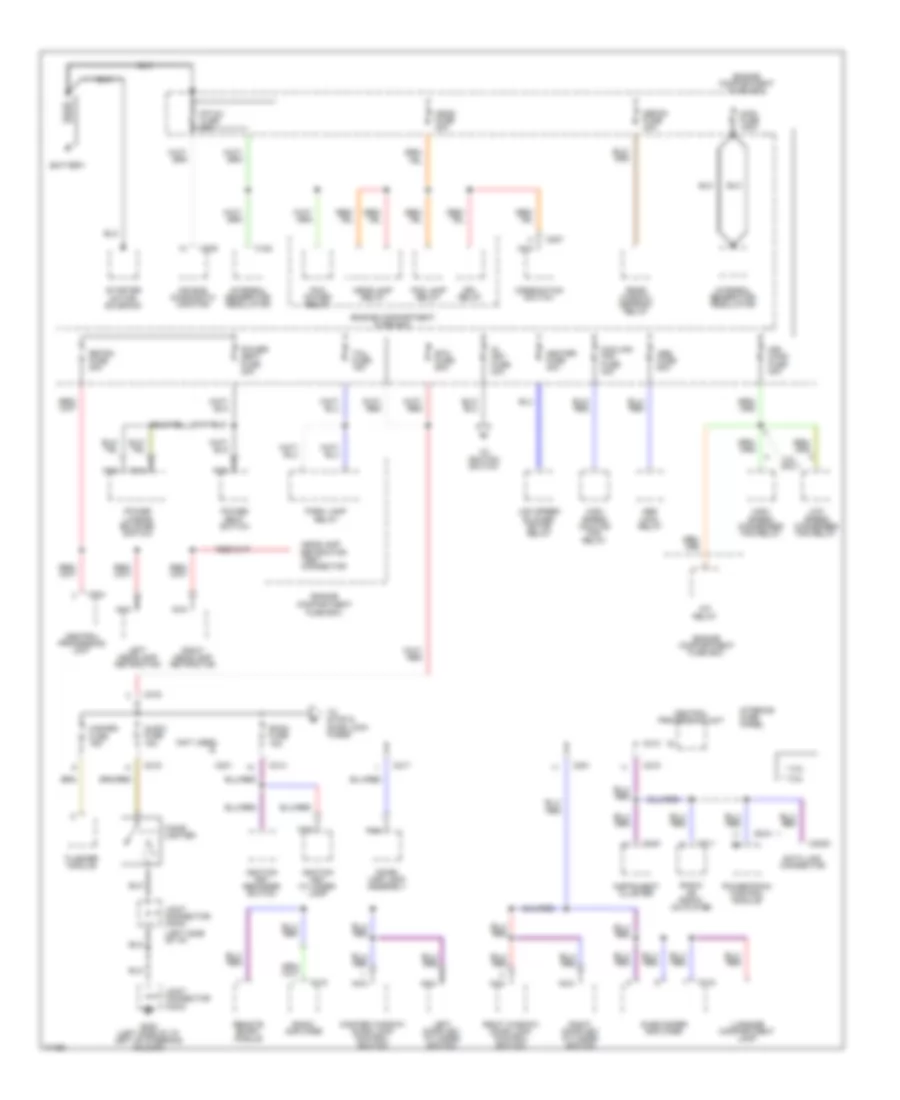
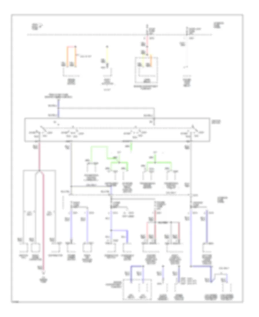
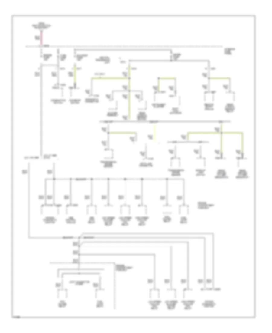
POWER DISTRIBUTION Power Distribution Wiring Diagram (1 of 3) for Ford Probe SE 1996 List of elements for Power Distribution Wiring Diagram (1 of 3) for Ford Probe SE 1996: 85 (left side of i/p) (not used) * 2.0l ** 2.5l 2.5l only A/c relay Abs fuse 60a Abs main relay Air bag diagnostic monitor Air- cond fuse 40a Audio fuse 15a Battery Btn fuse 60a C153 C201 C2020 C204 C207 C209 C211 C213 C214 C215 C216 C217 C240 C248 C315 C318 Central processing unit Cigar lighter Combination switch Cooling fan fuse 40a Data link connector Defog fuse 40a Dome/ map lamp assembly Drl relay Engine compartment fuse box F/p inj fuse 30a Flasher module Fog lamp relay G202 (left side of i/p, left of steering column) Hazard fuse 15a Head fuse 30a Headlamp relay Headlamp retractor test connector Heater fuse 40a High speed condenser fan relay High speed cooling fan relay Ig key fuse 40a Ignition key cylinder lamp Ignition key reminder switch Instrument cluster Integral generator/ regulator Interior fuse panel Joint connector (c203) Joint connector (c234) Left door key cylinder switch Left headlamp retractor Low speed blower motor relay Low speed condenser fan relay Luggage compartment lamp Main fuse 100a Master window/ door lock control switch Nca Park lamp relay Pcm power relay Power lumbar bolster switch Power seat fuse 30a Power seat switch Powertrain control module Radio amplifier Radio or radio/ cd player Rear window defrost relay Remote entry module Retra fuse 20a Right door key cylinder switch Right headlamp retractor Right window/ door lock control switch Room fuse 15a Starter motor/ solenoid Subwoofer amplifier Tail fuse 15a To ignition switch To stop & door lock fuses Power Distribution Wiring Diagram (2 of 3) for Ford Probe SE 1996 List of elements for Power Distribution Wiring Diagram (2 of 3) for Ford Probe SE 1996: 63 (2.5l) (2.0l a/t) (2.0l m/t) (2.5l) (2.0l) (not used) 2.0l only 2.0l w/ a/t 2.5l only A/c relay A/t Acc Air-cond fuse 15a Brake on/off switch C170 C201 C211 C214 C215 C216 C225 C227 c110 c227 C241 C244 C246 Clock spring assembly Combination switch Daytime running lamps control module Distributor Door lock fuse 30a Drl relay Engine compartment fuse box From ig key fuse (engine compt fuse box) From room fuse High speed condenser fan relay Horn relay Ig1 Ig2 Ignition coil Ignition switch Instrument cluster Interior fuse panel Lock Low speed condenser fan relay M/t Master window/ door lock control switch Nca Power door lock relay Power mirror switch Power window fuse 30a Powertrain control module Radio fuse 15a Radio noise capacitor Radio or radio/cd player Right window/ door lock control switch Run Shift lock actuator Speed control module Start Starter clutch pedal position switch Stop fuse 20a To engine fuse Transmission range sensor W/ a/t Windshield wiper motor Wiper fuse 20a Power Distribution Wiring Diagram (3 of 3) for Ford Probe SE 1996 List of elements for Power Distribution Wiring Diagram (3 of 3) for Ford Probe SE 1996: 52 2.0l 2.0l only 2.0l w/ abs & 2.5l 2.0l w/o abs 2.5l a/t 2.5l m/t A/t Abs control module Abs main relay Air bag diagnostic monitor Back-up lamp switch Blower assembly C135 C201 C209 C213 C214 C215 C216 C217 C222 C225 C241 C407 Central processing unit Combination switch Data link connector Diagnostic connector Engine compartment fuse box Engine fuse 15a From ignition switch (run/start) Front heated oxygen sensor #12 Fuel pump relay High speed cooling fan relay Instrument cluster Interior fuse panel Joint connector (c1069) Low speed blower motor relay Low speed cooling fan relay M/t Meter fuse 15a Moonroof switch Nca Pcm power relay Rear heated oxygen sensor #11 Rear window defrost relay Rear window defrost switch Remote entry module Shift lock actuator Sun roof fuse 15a Transmission range sensor Turn fuse 15a
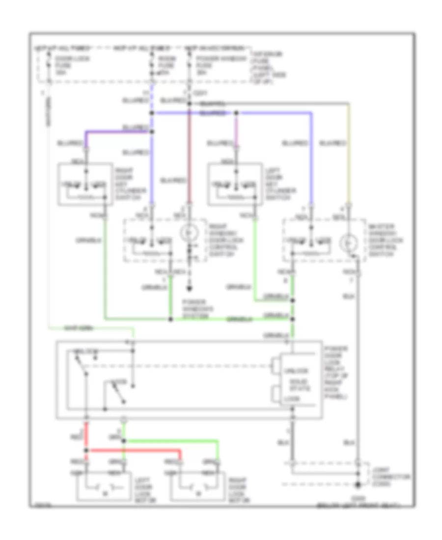
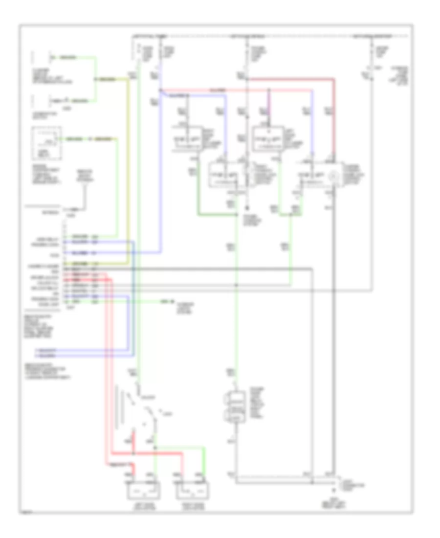
POWER DOOR LOCKS Door Lock Wiring Diagram for Ford Probe SE 1996 List of elements for Door Lock Wiring Diagram for Ford Probe SE 1996: 23 C201 Door lock fuse 30a G300 (below left front seat) Hot at all times Hot in acc or run Interior fuse panel (left side of i/p) Joint connector (c300) Left door key cylinder switch Left door lock motor Lock Master window/ door lock control switch Nca Power door lock relay (top of right kick panel) Power window fuse 30a Power windows system Red Right door key cylinder switch Right door lock motor Right window/ door lock control switch Room fuse 15a Solid state Unlck Unlock Keyless Entry Wiring Diagram for Ford Probe SE 1996 List of elements for Keyless Entry Wiring Diagram for Ford Probe SE 1996: 47 Antenna C201 C225 C407 C425 Coil Combination switch Dome lamp Door lock fuse 30a Dr lock relay Driver unlock Engine compartment fuse box (left side of engine compt.) Flasher module (behind i/p, left of steering column) G300 (below left front seat) Gnd Hazard flasher Horn relay Hot at all times Hot in acc or run Hot in run or start Ign Interior fuse panel (left side of i/p) Interior lights system Joint connector (c300) Left door key cylinder switch Left door lock motor Lock Master window/ door lock control switch Meter fuse 15a Nca Power door lock relay (top of right kick panel) Power window fuse 30a Power windows system Program conn Pwr Red Remote entry antenna Remote entry module (in front of right quarter panel, behind quarter trim) Remote entry program connector (in right rear of luggage compartment) Right door key cylinder switch Right door lock motor Right window/ door lock control switch Room fuse 15a Solid state Unlck Unlock Unlock all
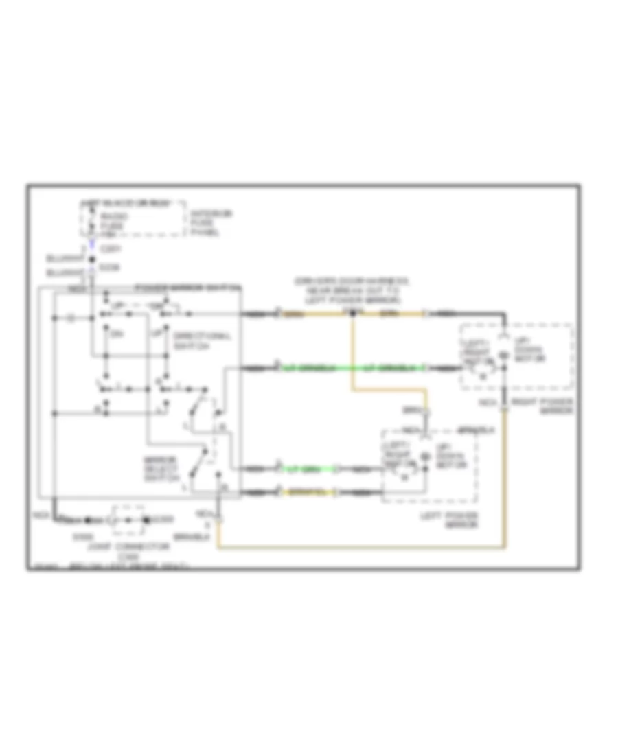
POWER MIRRORS Power Mirror Wiring Diagram for Ford Probe SE 1996 List of elements for Power Mirror Wiring Diagram for Ford Probe SE 1996: 17 (driver's door harness, near break out to left power mirror) s504 C201 Directional switch G300 Hot in acc or run Interior fuse panel Joint connector c300 (below left front seat) Left power mirror Left/ right motor Mirror select switch Nca Power mirror switch Radio fuse 15a Right power mirror S238 S500 Up/ down motor
POWER SEATS Power & Lumbar Seat Wiring Diagram for Ford Probe SE 1996 List of elements for Power & Lumbar Seat Wiring Diagram for Ford Probe SE 1996: 22 (lower center rear of luggage compartment) Engine compartment fuse box Fwd Fwd/rwd slide switch G407 Hot at all times Joint connector (c400) Lift switch Lumbar support switch Nca Not used Power lumbar/ bolster compressor motor Power lumbar/ bolster switch Power seat fuse 30a Power seat lift motor Power seat slide motor Power seat switch Power seat tilt motor Red Rwd Side support switch Tilt switch
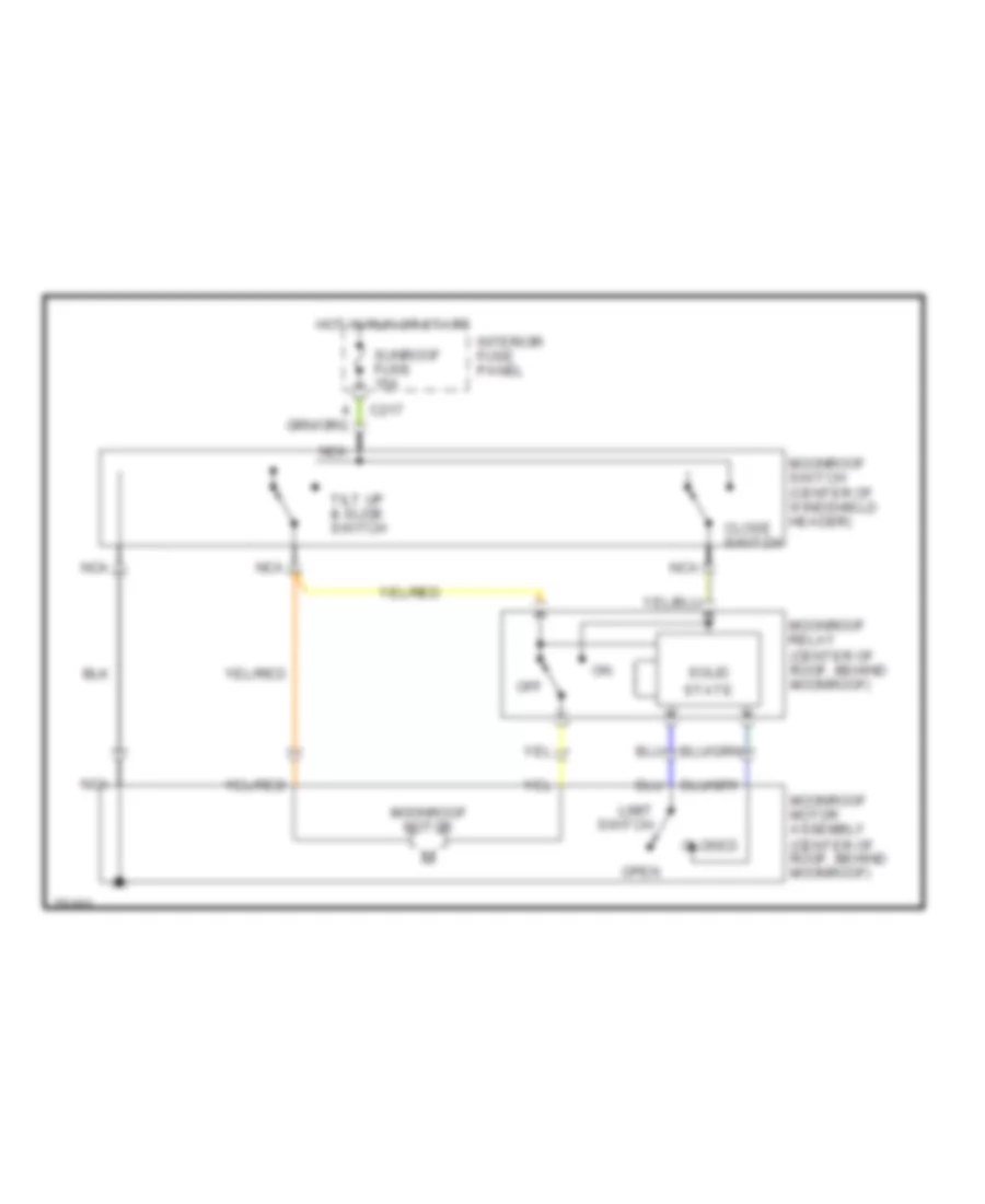
POWER TOP/SUNROOF Power Top/Sunroof Wiring Diagrams for Ford Probe SE 1996 List of elements for Power Top/Sunroof Wiring Diagrams for Ford Probe SE 1996: 16 C217 Close switch Closed Hot in run or start Interior fuse panel Limit switch Moonroof motor Moonroof motor assembly (center of roof, behind moonroof) Moonroof relay (center of roof, behind moonroof) Moonroof switch (center of windshield header) Nca Off Open Solid state Sunroof fuse 15a Tilt up & slide switch
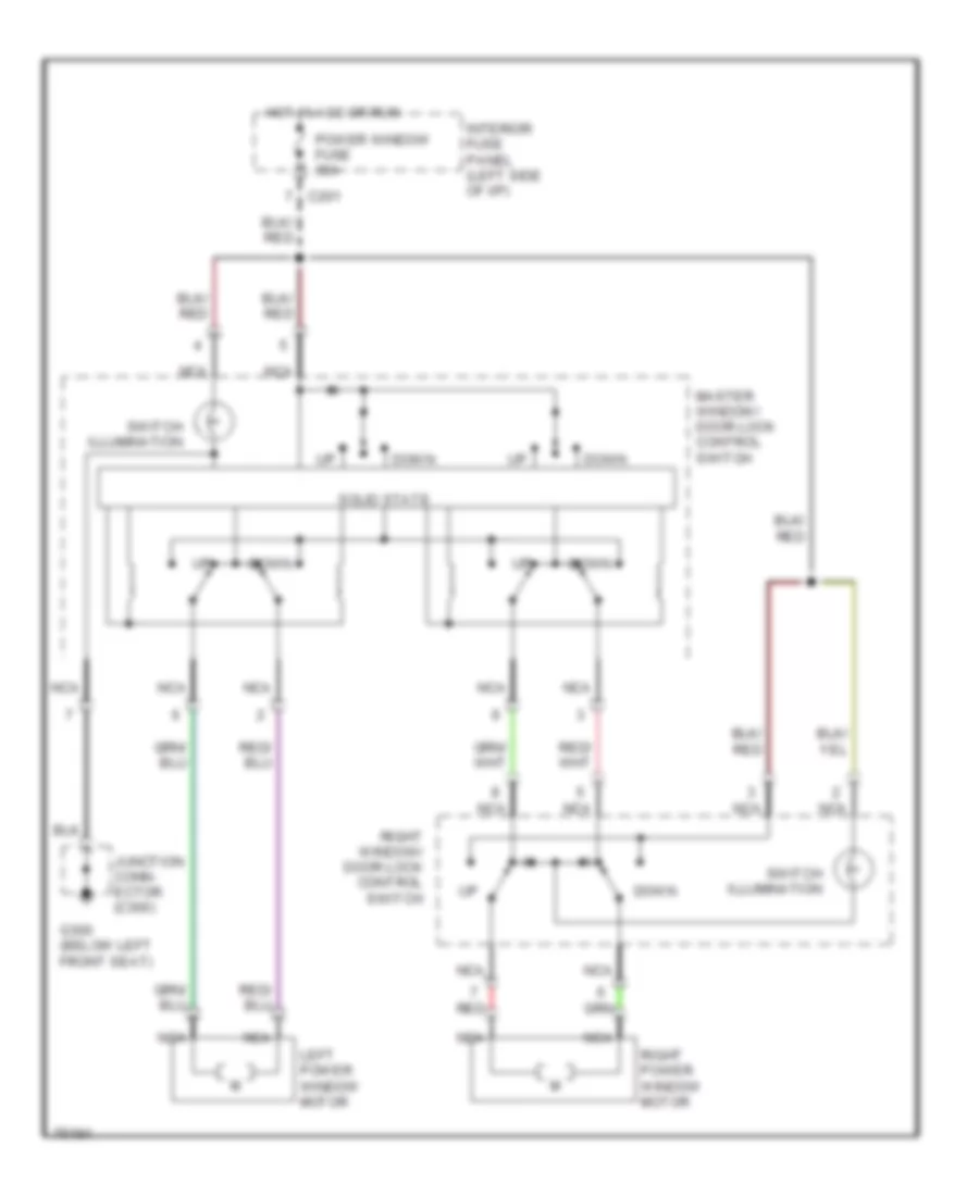
POWER WINDOWS Power Window Wiring Diagram for Ford Probe SE 1996 List of elements for Power Window Wiring Diagram for Ford Probe SE 1996: 15 C201 Down G300 (below left front seat) Hot in acc or run Interior fuse panel (left side of i/p) Junction conn- ector (c300) Left power window motor Master window/ door lock control switch Nca Power window fuse 30a Red Right power window motor Right window/ door lock control switch Solid state Switch illumination
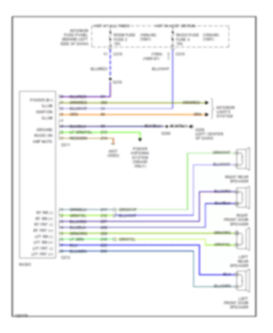
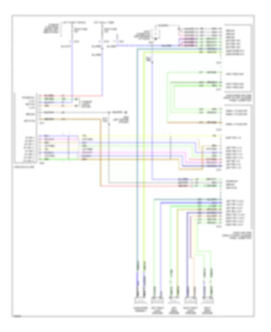
RADIO Base Radio for Ford Probe SE 1996 List of elements for Base Radio for Ford Probe SE 1996: 36 (1994) (1994-96) (1997) (1995-97) (not used) Amp mute C211 C212 C215 G206 (left center of dash) Ground Hot at all times Hot in accy or run Ignition Illum Interior fuse panel (behind left side of dash) Interior lights system Left front door speaker Left rear speaker Lft frt (+) Lft frt (-) Lft rr (+) Lft rr (-) Power (b+) Power antenna system (1994-95 only) Radio Radio fuse fuse 4 15a Radio on Right front door speaker Right rear speaker Room fuse fuse 2 15a Rt frt (+) Rt frt (-) Rt rr (+) Rt rr (-) S200 S216 Premium Sound Radio Wiring Diagram for Ford Probe SE 1996 List of elements for Premium Sound Radio Wiring Diagram for Ford Probe SE 1996: 60 Amp mute Battery (b+) C201 C211 C215 C291 C314 C315 C316 C317 C318 G206 (left center of dash) G407 Ground Hot at all times Hot in accy or run Ignition Illum Input from amp Interior fuse panel (behind left side of dash) Interior lights system Joint connector (center rear of trunk) Left front door speaker Left frt (+) in Left frt (+) out Left frt (-) in Left frt (-) out Left rear speaker Left rr (+) in Left rr (+) out Left rr (-) in Left rr (-) out Lft frt (+) Lft frt (-) Lft rr (+) Lft rr (-) Nca Power (b+) Radio amplifier (front of right quarter panel, under trim) Radio fuse 15a Radio/cd player Right front door speaker Right frt (+) in Right frt (+) out Right frt (-) in Right frt (-) out Right rear speaker Right rr (+) in Right rr (+) out Right rr (-) in Right rr (-) out Room fuse 15a Rt frt (+) Rt frt (-) Rt rr (+) Rt rr (-) Signal to sub amp Subwoofer amplifier (front of left quarter panel, under trim) Subwoofer assembly Subwoofer out
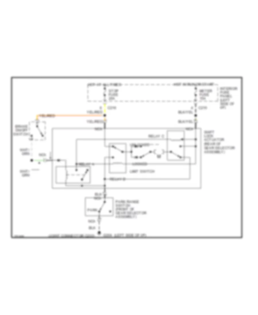
SHIFT INTERLOCKS Shift Interlock Wiring Diagram for Ford Probe SE 1996 List of elements for Shift Interlock Wiring Diagram for Ford Probe SE 1996: 21 (joint connector c203) (left side of i/p) Brake on/off switch C215 C216 G204 Hot at all times Hot in run or start Interior fuse panel (left side of i/p) Limit switch Locked Meter fuse 15a Nca Park Park range switch (front of gear selector assembly) Relay a Relay b Relay c Shift lock actuator (rear of gear selector assembly) Stop fuse 20a Unlocked
STARTING/CHARGING
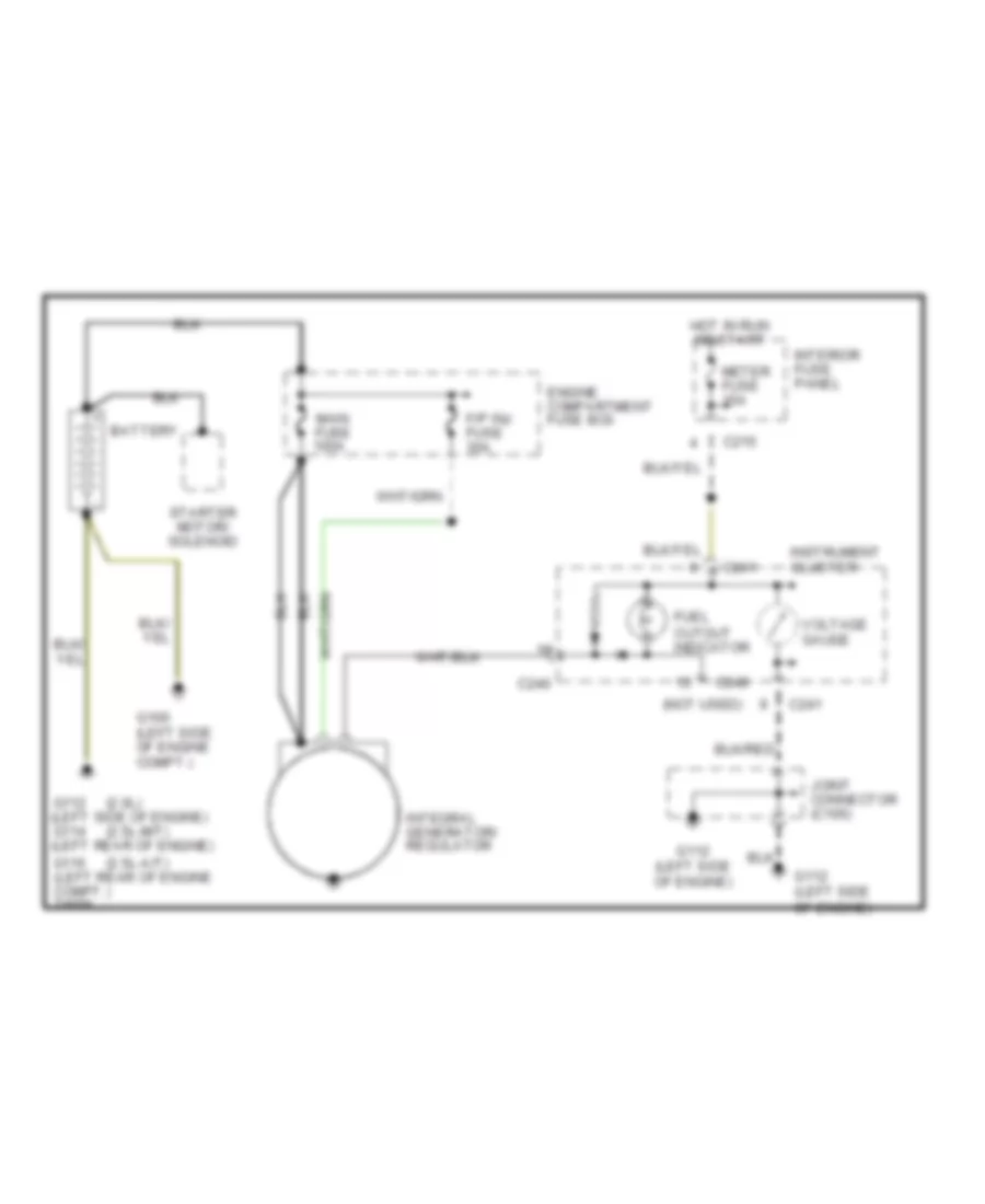
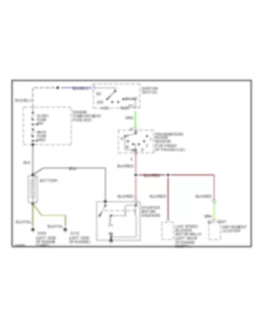
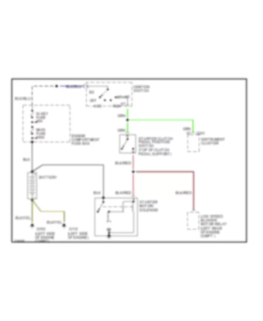
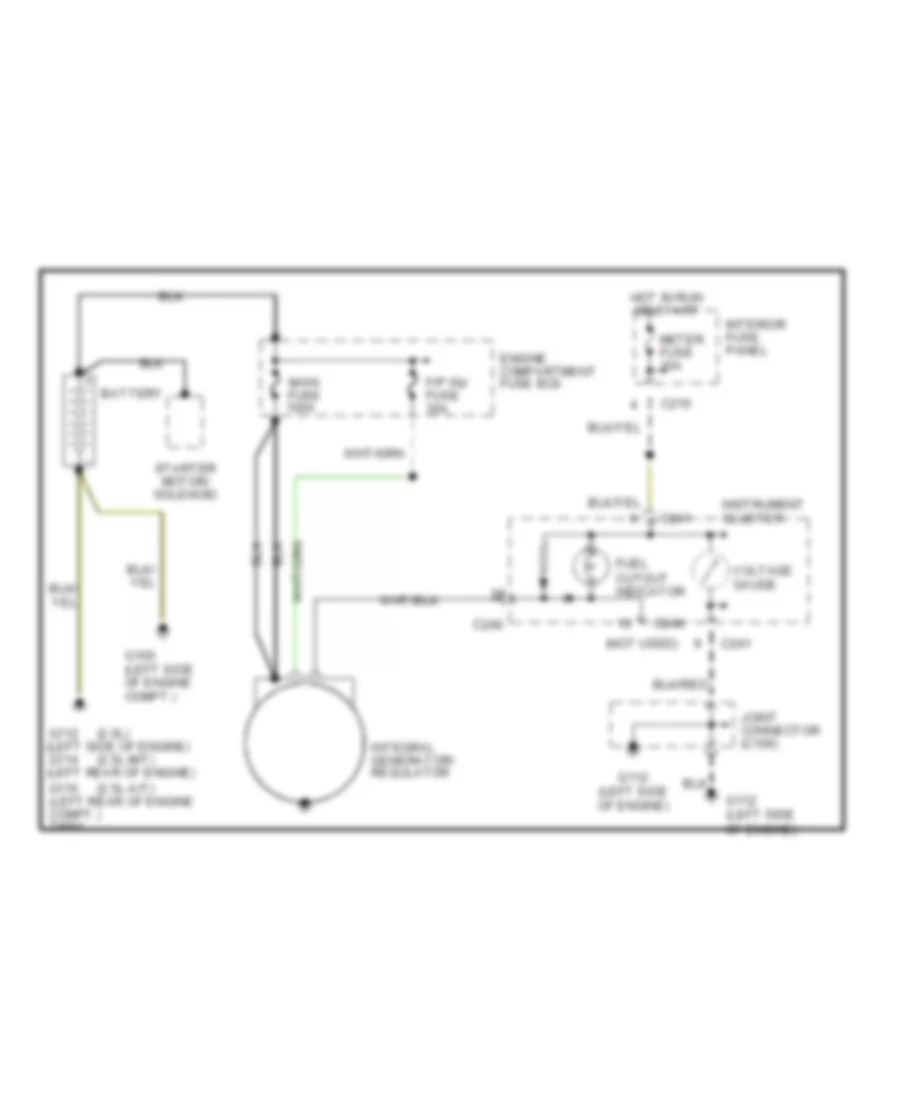
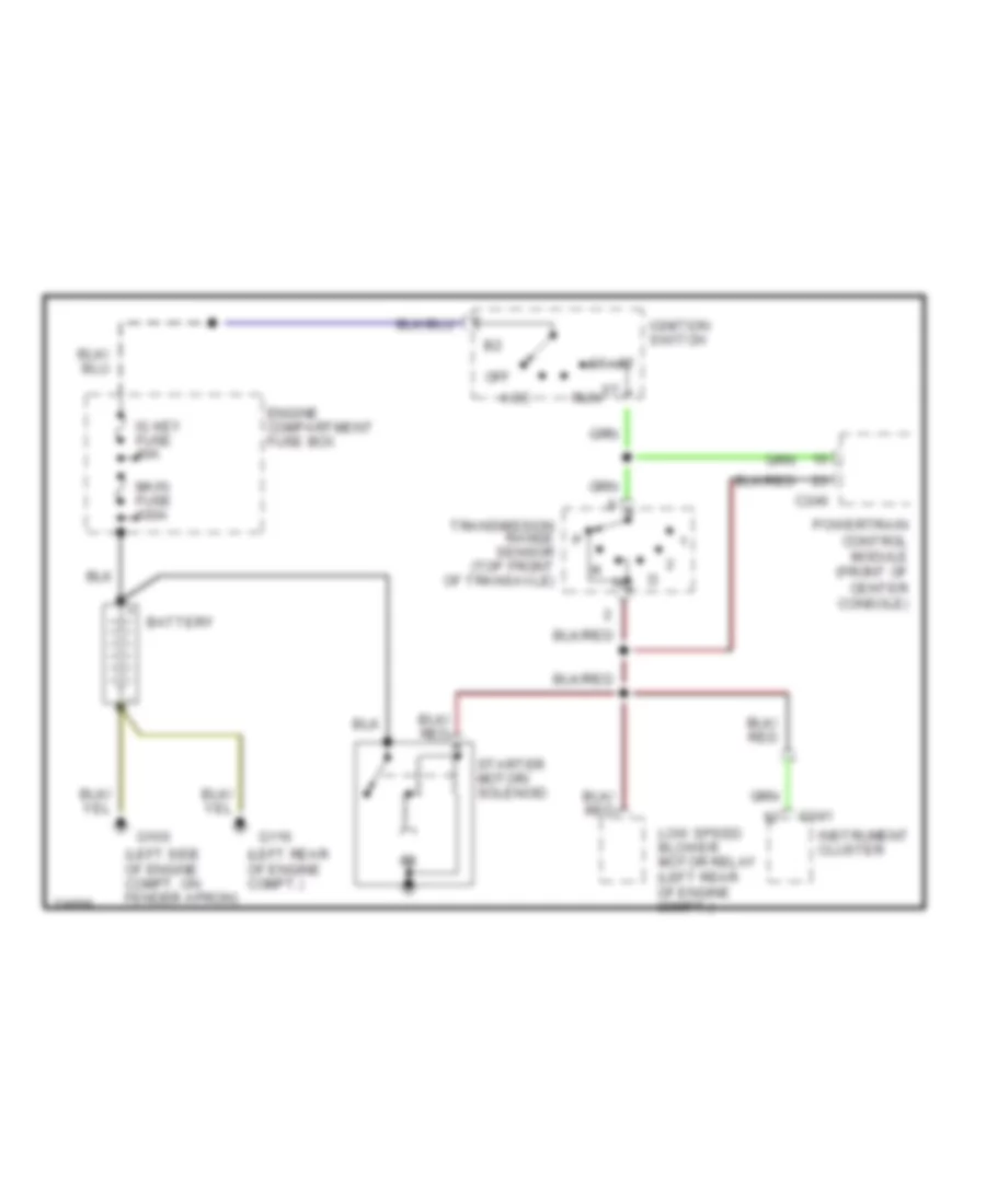
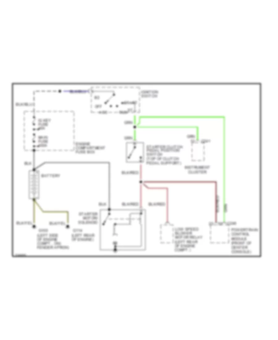
2.0L 2.0L, Charging Wiring Diagram for Ford Probe SE 1996 List of elements for 2.0L, Charging Wiring Diagram for Ford Probe SE 1996: 25 (2.0l) (2.5l-a/t) (2.5l-m/t) (not used) Battery C215 C240 C241 Cluster Engine compartment fuse box F/p inj fuse 30a Fuel cutout indicator G100 (left side of engine compt.) G112 (left side of engine) G112 (left side of engine) g114 (left rear of engine) G116 (left rear of engine compt.) Hot in run or start Instrument Integral generator/ regulator Interior fuse panel Joint connector (c106) Main fuse 100a Meter fuse 15a Starter motor/ solenoid Voltage gauge 2.0L, Starting Wiring Diagram, with A/T for Ford Probe SE 1996 List of elements for 2.0L, Starting Wiring Diagram, with A/T for Ford Probe SE 1996: 18 (left side of engine compt) (left side of engine) Acc Battery C241 Engine compartment fuse box G100 G112 Ig key fuse 40a Ignition switch Instrument cluster Low speed blower motor relay (left rear of engine compt.) Main fuse 100a Off Run Start Starter motor/ solenoid Transmission range sensor (top front of transaxle) 2.0L, Starting Wiring Diagram, with M/T for Ford Probe SE 1996 List of elements for 2.0L, Starting Wiring Diagram, with M/T for Ford Probe SE 1996: 18 (left side of engine compt) (left side of engine) Acc Battery C241 Engine compartment fuse box G100 G112 Ig key fuse 40a Ignition switch Instrument cluster Low speed blower motor relay (left rear of engine compt.) Main fuse 100a Off Run Start Starter clutch pedal position switch (top of clutch pedal support) Starter motor/ solenoid
2.5L 2.5L, Charging Wiring Diagram for Ford Probe SE 1996 List of elements for 2.5L, Charging Wiring Diagram for Ford Probe SE 1996: 25 (2.0l) (2.5l-a/t) (2.5l-m/t) (not used) Battery C215 C240 C241 Cluster Engine compartment fuse box F/p inj fuse 30a Fuel cutout indicator G100 (left side of engine compt.) G112 (left side of engine) G112 (left side of engine) g114 (left rear of engine) G116 (left rear of engine compt.) Hot in run or start Instrument Integral generator/ regulator Interior fuse panel Joint connector (c106) Main fuse 100a Meter fuse 15a Starter motor/ solenoid Voltage gauge 2.5L, Starting Wiring Diagram, with A/T for Ford Probe SE 1996 List of elements for 2.5L, Starting Wiring Diagram, with A/T for Ford Probe SE 1996: 20 (left rear of engine compt.) (left side of engine compt. on fender apron) Acc Battery C241 C246 Engine compartment fuse box G100 G116 Ig key fuse 40a Ignition switch Instrument cluster Low speed blower motor relay (left rear of engine compt.) Main fuse 100a Off Powertrain control module (front of center console) Run Start Starter motor/ solenoid Transmission range sensor (top front of transaxle) 2.5L, Starting Wiring Diagram, with M/T for Ford Probe SE 1996 List of elements for 2.5L, Starting Wiring Diagram, with M/T for Ford Probe SE 1996: 20 (left rear of engine) (left side of engine compt., on) fender apron) Acc Battery C241 C246 Engine compartment fuse box G100 G114 Ig key fuse 40a Ignition switch Instrument cluster Low speed blower motor relay (left rear of engine compt.) Main fuse 100a Off Powertrain control module (front of center console) Run Start Starter clutch pedal position switch (top of clutch pedal support) Starter motor/ solenoid
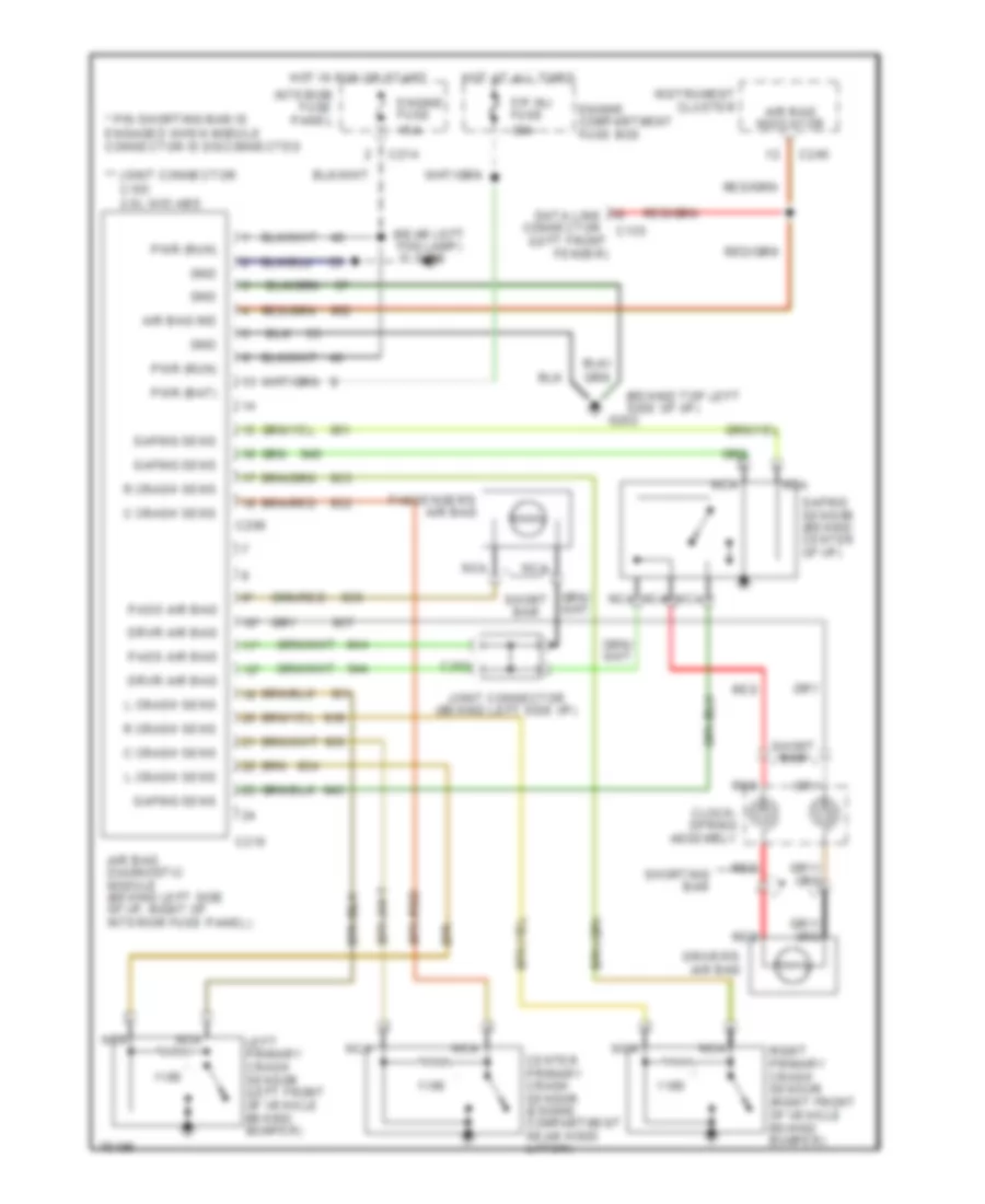
SUPPLEMENTAL RESTRAINTS Supplemental Restraint Wiring Diagram for Ford Probe SE 1996 List of elements for Supplemental Restraint Wiring Diagram for Ford Probe SE 1996: 47 (behind top left side of i/p) (near left fog lamp) g106 * pin shorting bar is engaged when module connector is disconnected ** joint connector 10* 11* 12* Air bag diagnostic module (behind left side of i/p, right of interior fuse panel) Air bag ind Air bag indicator C crash sens C103 2.0l w/o abs C135 C209 C210 C214 C240 C262 Center primary crash sensor (engine compartment near hood latch) Clock- spring assembly Data link connector (left front fender) Driver's air bag Drvr air bag Engine compartment fuse box Engine fuse 15a F/p inj fuse 30a G202 Gnd Hot at all times Hot in run or start Instrument cluster Interior fuse panel Joint connector (behind left side i/p) L crash sens Left primary crash sensor (left front of vehicle behind bumper) Nca Pass air bag Passenger's air bag Pwr (bat) Pwr (run) R crash sens Red Right primary crash sensor (right front of vehicle behind bumper) Safing sens Safing sensor (behind center of i/p) Short bar Shorting bar
TRANSMISSION
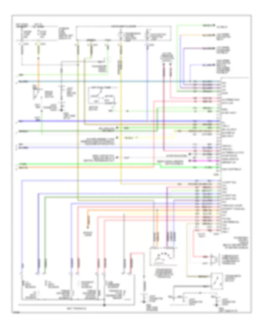
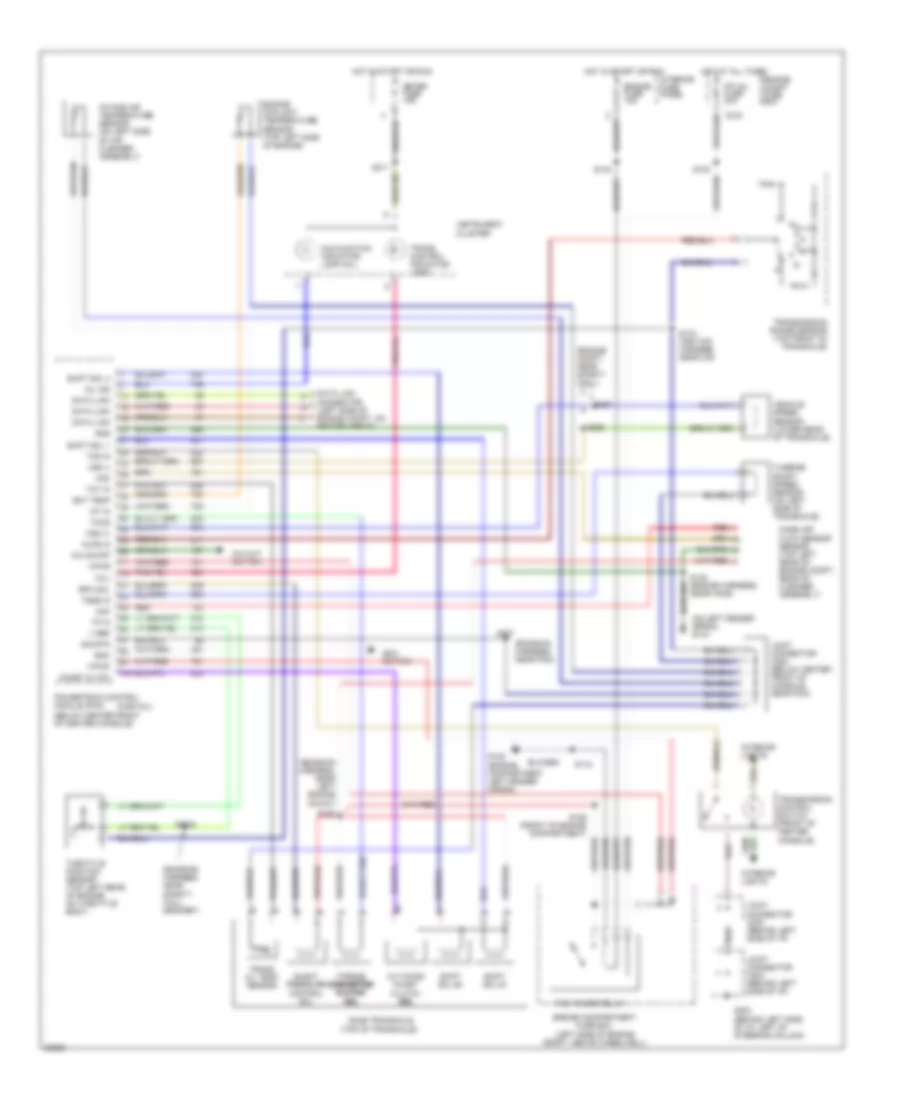
2.0L 2.0L, Transmission Wiring Diagram for Ford Probe SE 1996 List of elements for 2.0L, Transmission Wiring Diagram for Ford Probe SE 1996: 85 (behind left side of i/p, left of steering column) (below center front of center console) (emission harness, near pcm) (emission harness, near safety wall grommet) (emission harness, near left engine mount) (engine compartment, left fender apron) (engine compt, near safety wall) (on left fender apron) g104 (partial) (top of transaxle) 3-2 timing/ coast clutch sol sol sol sol A/c cut out sw. A/c on/off Boo Boo switch C215 Cd4e transaxle Coast cltch Data link Data link connector (left side of engine compt, on fender apron) Ect temp Elect pressure control sol Engine compartment fuse box (left side of engine compt, above wheelwell) Engine compt fuse box Engine coolant temperature sensor (top left side of engine) Engine fuse 15a Epc sol F/p inj fuse 30a G102 G204 Gnd Hot at all times Hot in start or run Iat in Instrument cluster Intake air temperature sensor (on left side of air cleaner assembly) Interior fuse panel Interior lights Joint connector c203 (behind left side of i/p) Joint connector c234 (behind left side of i/p) Joint connector c264 (below center front of console, near pcm) Maf Malfunction indicator lamp (mil) Mass air flow sensor sensor (top left rear of engine compt, rear of cleaner assembly) Meter fuse 15a Mil ind Mlps in Pcm power relay Powertrain control module (pcm) Red S102 S118 S133 (ignition harness, near icm) S138 (engine harness, near ho2s) S143 S163 S189 (front of engine compartment) S2003 S287 S291 S292 S311 Shift sol #1 Shift sol #2 Shift sol 1 Shift sol 2 Sig rtn Tccs Tcil Tcs in Throttle position sensor (top left rear of engine, on throttle body) Torque converter converter converter converter clutch clutch clutch clutch sol sol sol sol Tot in Tp in Trans oil temp sensor Trans. control indicator lamp Transmission control switch (front of center console) Transmission range sensor (top front of transaxle) Tsss in Turbine shaft speed sensor (on left side of transaxle) V ref Vehicle speed sensor (lower rear of transaxle) Vpwr Vss (+) Vss (-)
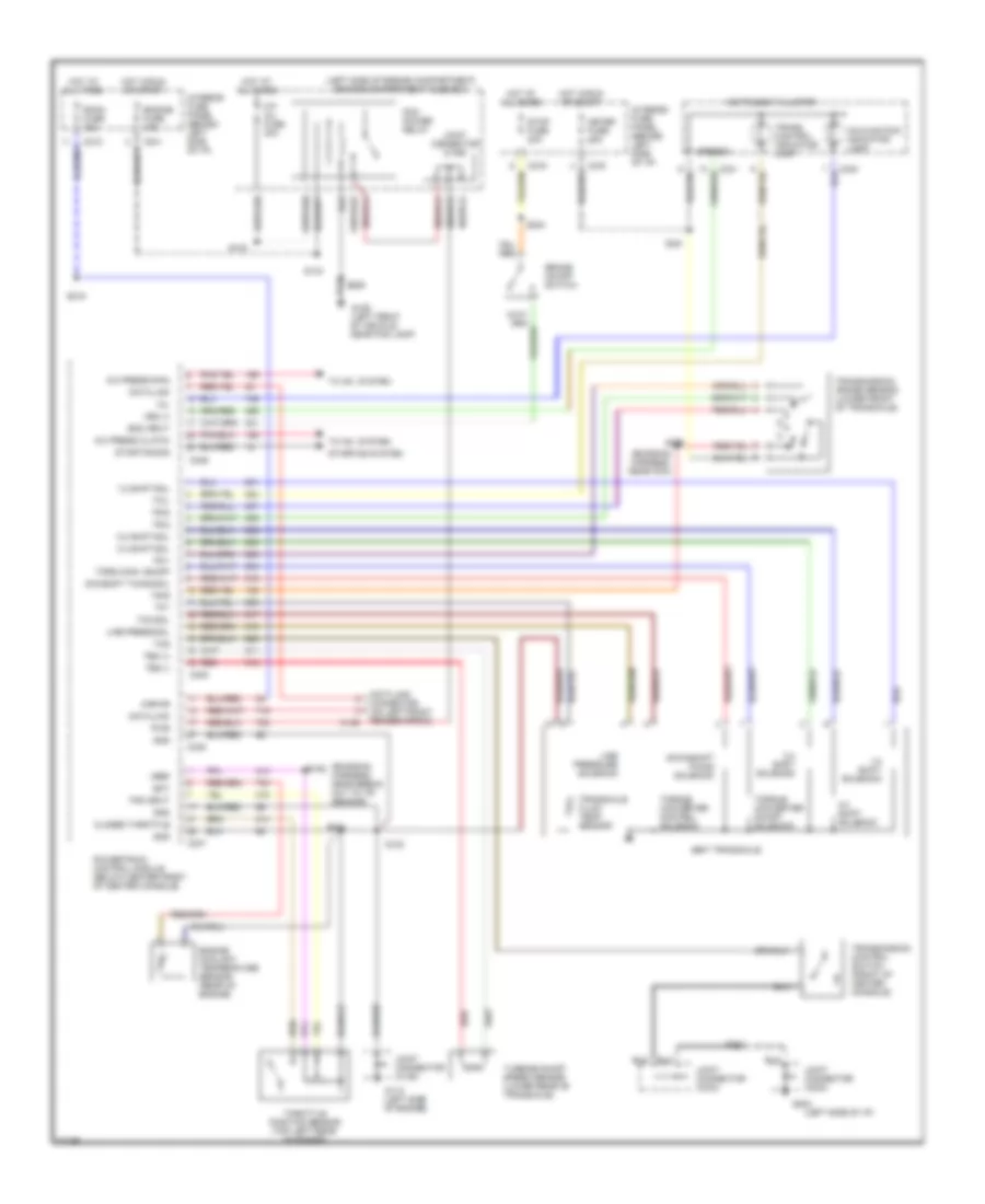
2.5L 2.5L, Transmission Wiring Diagram for Ford Probe SE 1996 List of elements for 2.5L, Transmission Wiring Diagram for Ford Probe SE 1996: 94 (emission harness, near break out to tr sensor) (emission harness, near pcm) (left side of engine compartment) engine compartment fuse box (left side of i/p) 1-2 shift sol 1-2 shift solenoid 2-3 shift sol 2-3 shift solenoid 3-4 shift sol 3-4 shift solenoid 4eat transaxle A/c press (fan) A/c press clutch Boo input Brake on/off switch C135 C214 C215 C216 C245 C246 C247 C248 Closed throttle Data link Data link connector (on left front fender apron) Downshift timing solenoid Dwnshft timing sol Ect Engine coolant temperature sensor (rear of engine) Engine fuse 15a F/p inj fuse 30a G106 (left front of vehicle, near fog lamp) G112 (left side of engine) G202 Gnd Hot at all times Hot in run or start Instrument cluster Interior fuse panel (behind left side of i/p) Interior fuse panel (behind left side of i/p) Joint connector (c106) Joint connector (c169) Joint connector (c203) Joint connector (c234) Kapwr Line press sol Line pressure solenoid Malfunction indicator lamp Meter fuse 15a Mil Pcm power relay Powertrain control module (below center front of center console) Pwr Red Room fuse 15a S102 S123 S143 S193 S204 S206 S211 S213 S215 S241 S279 Speedo Starting sig Starting system Stop fuse 20a Tcc sol Tcil Tcs Tft Throttle position sensor (top left rear of engine) To a/c system Torq conv on/off Torque converter control solenoid Torque converter on/off solenoid Tps input Tr-1 Tr-2 Tr-d Tr-r Trans. control indicator lamp Transaxle fluid temp. sensor Transmission control switch (front of center console) Transmission range sensor (lower front of transaxle) Tss (+) Tss (-) Turbine shaft speed sensor (lower rear of transaxle) Vref Vss (+)
WARNING SYSTEMS Warning System Wiring Diagrams for Ford Probe SE 1996 List of elements for Warning System Wiring Diagrams for Ford Probe SE 1996: 35 (left side of i/p) (not used) Bat C201 C213 C214 C215 C240 C241 Central processing unit Door input Exterior lights system Exterior lights system (park lamp relay) Fasten seat belt indicator Fasten seat belt indicator output G300 (lower center rear of luggage compt.) Ground Hot at all times Hot in run or start Ign Ignition key reminder switch Ignition key reminder switch input Instrument cluster Interior fuse panel Interior fuse panel (left side of i/p) Interior lights system Joint connector (c400) Left door courtesy lamp switch Meter fuse 15a Meter room 15a Nca Park & head lamps on circuit Right door courtesy lamp switch Room fuse 15a Seat belt buckle switch
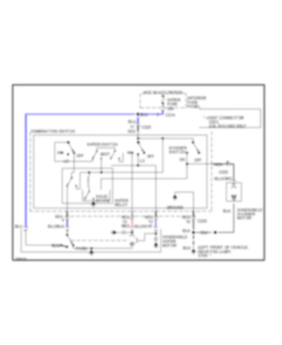
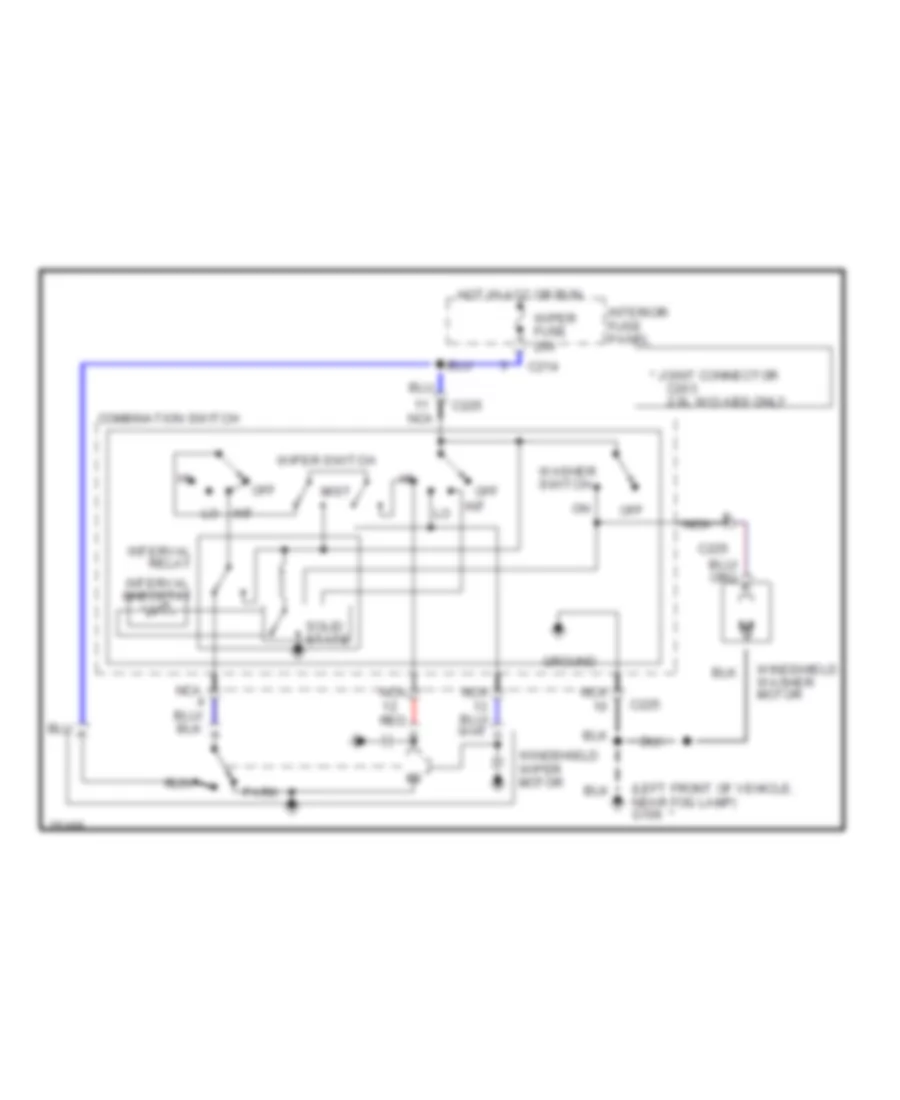
WIPER/WASHER 2-Speed Wiper/Washer Wiring Diagram for Ford Probe SE 1996 List of elements for 2-Speed Wiper/Washer Wiring Diagram for Ford Probe SE 1996: 22 (left front of vehicle, near fog lamp) g106 * joint connector C203 2.0l w/o abs only C214 C225 Combination switch Ground Hot in acc or run Interior fuse panel Mist Nca Off Park Red Run Solid state Washer switch Windshield washer motor Windshield wiper motor Wiper fuse 20a Wiper relay Wiper switch Interval Wiper/Washer Wiring Diagram for Ford Probe SE 1996 List of elements for Interval Wiper/Washer Wiring Diagram for Ford Probe SE 1996: 24 (left front of vehicle, near fog lamp) g106 * joint connector C203 2.0l w/o abs only C214 C225 Combination switch Ground Hot in acc or run Int Interior fuse panel Interval relay Interval rheostat Mist Nca Off Park Red Run Solid state Washer switch Windshield washer motor Windshield wiper motor Wiper fuse 20a Wiper switch