Diagram sections — 24 (53 total)
AIR CONDITIONING ANTI-LOCK BRAKES ANTI-THEFT BODY COMPUTER COMPUTER DATA LINES CRUISE CONTROL ENGINE PERFORMANCE EXTERIOR LIGHTS GROUND DISTRIBUTION HEADLIGHTS HORN INSTRUMENT CLUSTER INTERIOR LIGHTS POWER DISTRIBUTION POWER DOOR LOCKS POWER MIRRORS POWER WINDOWS RADIO SHIFT INTERLOCKS STARTING/CHARGING SUPPLEMENTAL RESTRAINTS TRANSMISSION WARNING SYSTEMS WIPER/WASHER
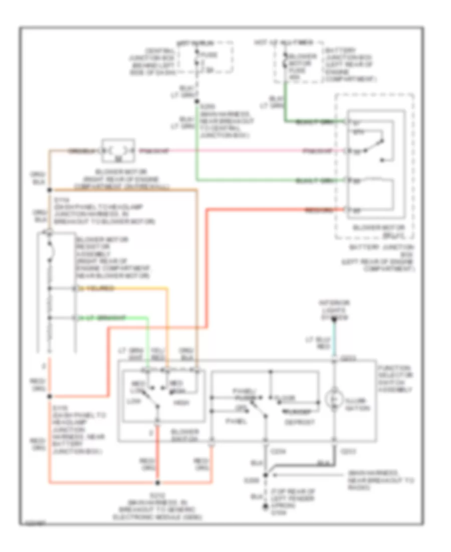
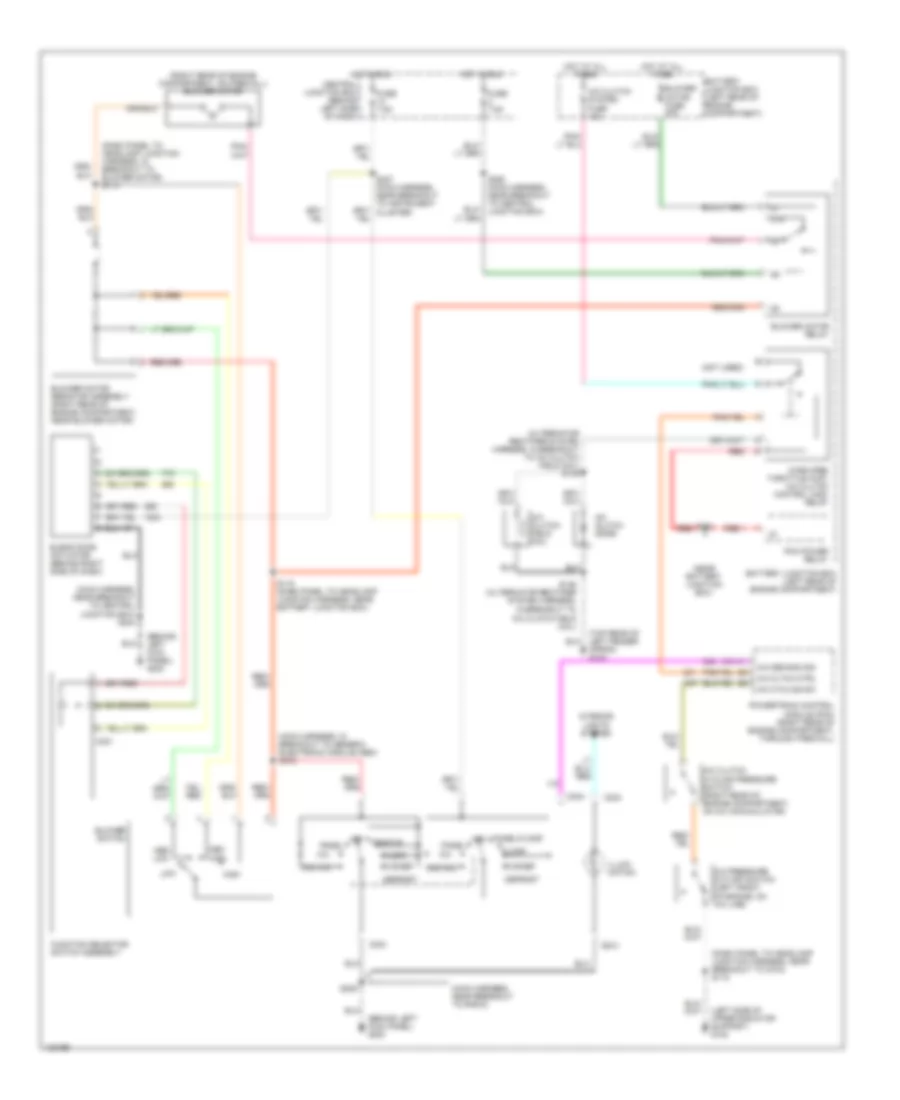
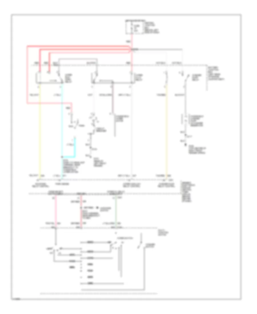
AIR CONDITIONING Heater Wiring Diagram for Ford Ranger 2000 List of elements for Heater Wiring Diagram for Ford Ranger 2000: 33 (main harness, near breakout to radio) (top rear of left fender apron) g104 87a Battery junction box (left rear of engine compartment) Blower motor (right rear of engine compartment on firewall) Blower motor fuse 40a Blower motor relay Blower motor resistor assembly (right rear of engine compartment, near blower motor) Blower switch C233 C234 Central junction box (behind left side of dash) Defrost Floor Flr/def Function selector switch assembly Fuse 7.5a High Hot at all times Hot in run Illumi- nation Interior lights system Low Med high Med low Off Panel Panel/ floor S114 (dash panel to headlamp junction harness, in breakout to blower motor) S115 (dash panel to headlamp junction harness, near battery junction box) S209 S212 (main harness, in breakout to generic electronic module (gem)) S250 (main harness, near breakout to central junction box) Manual A/C Wiring Diagram for Ford Ranger 2000 List of elements for Manual A/C Wiring Diagram for Ford Ranger 2000: 61 (alternator rectifier system harness, in breakout to a/c clutch field coil) s145 (behind left kick panel) g200 (dash panel to headlamp junction harness, in breakout to blower motor) s114 (dash panel to headlamp junction harness, near breakout to g104) s118 (left side of upper radiator support) g108 (main harness, in breakout to generic electronic module (gem) s212 (main harness, near breakout to radio) (main harness, near breakout to central junction box) s244 (near battery junction box) (not used) (right rear of engine compartment, on firewall) blower motor (top rear of left fender apron) g104 87a A/c A/c cltch ctrl A/c clutch cycling pressure switch (right rear of engine compartment, on a/c accumulator) A/c clutch diode A/c clutch field coil A/c clutch system fuse 10a A/c cycling sw A/c demand sig A/c pressure cut-off switch (left front of engine, on a/c line) Battery junction box (left rear of engine compartment) Blend door actuator (behind right side of dash) Blower motor fuse 40a Blower motor relay Blower motor resistor assembly (right rear of engine compartment, near blower motor) Blower switch C231 C233 C234 Central junction box (behind left side of dash) Defrost Floor Flr/def Function selector switch assembly Fuse 7.5a High Hot at all times Hot in run Illumi- nation In breakout to a/c clutch field coil) Interior lights system Low Max a/c Med high Med low Off Pan/flr Panel Panel/floor Pcm power relay Powertrain control module (pcm) (right rear of engine compartment, through firewall) Red S115 (dash panel to headlamp junction harness, near battery junction box) S121 S146 (alternator rectifier system harness, S209 S227 (main harness, near breakout to instrument cluster) S250 (main harness, near breakout to central junction box) Wide open throttle (wot) a/c clutch control (acc) relay
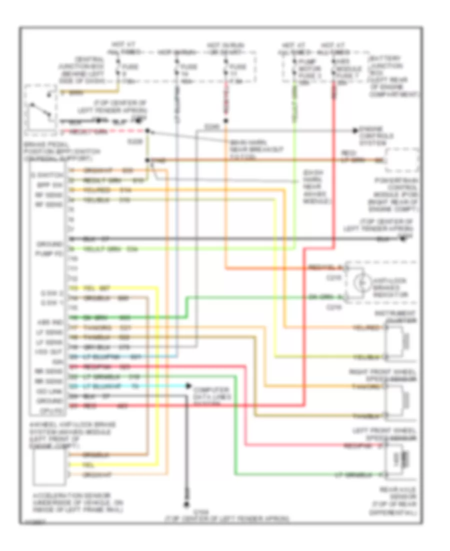
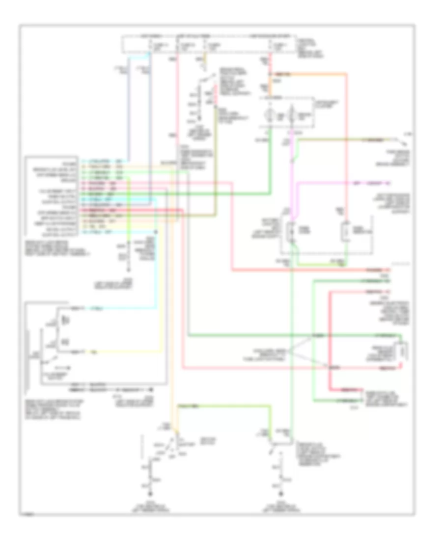
ANTI-LOCK BRAKES All-Wheel ABS Wiring Diagram for Ford Ranger 2000 List of elements for All-Wheel ABS Wiring Diagram for Ford Ranger 2000: 48 (dash harn, near 4wabs module) (main harn, near breakout to tcs) (top center of left fender apron) (top center of left fender apron) g104 4-wheel anti-lock brake system (4wabs) module (left front of engine compt) Abs ind Abs module fuse 7 30a red Acceleration sensor (underside of vehicle, on inside of left frame rail) Anti-lock brakes indicator Battery junction box (left rear of engine compartment) Bpp sw Brake pedal position (bpp) switch (on pedal support) C215 C216 Central junction box (behind left side of dash) Computer data lines system Cpu fd Differential) Engine controls system Fuse 10a Fuse 7.5a G sw 1 G sw 2 G switch G104 Ground Hot at all times Hot in run Hot in run or start Ign Instrument cluster Iso link Left front wheel speed sensor Lf sens Ohms Powertrain control module (pcm) (right rear of engine compt) Pump fd Pump motor fuse 3 50a Rear axle sensor (top of rear Red Red/pnk Rf sens Right front wheel speed sensor Rr sens S142 S228 S240 Vss out Rear Wheel ABS Wiring Diagram for Ford Ranger 2000 List of elements for Rear Wheel ABS Wiring Diagram for Ford Ranger 2000: 73 (main harn, near breakout to fuse junction panel) (top center of left fender apron) 1.2 ohms 22k ohms 4.0 ohms Abs ind Acc Battery junction box (left rear of engine compt) Bpp switch input Brake fluid level sw Brake fluid level switch (left rear of engine compartment, on brake fluid reservoir) Brake ind Brake pedal position (bpp) switch (behind left side of dash, on brake pedal support) C141 C215 C216 C222 C224 C244 Central junction box (behind left side of dash) Daytime running lamps (drl) module (left side of lower radiator Diff speed sens (hi) Diff speed sens (lo) Dump sol Dump sol output Fuse 11 7.5a Fuse 14 20a Fuse 30 10a Fuse 9 7.5a G104 G104 (top center of left fender apron) G108 (left side of upper radiator support) Generic electronic module (gem)/ central timer module (ctm) (behind center of dash) Gnd Ground Hot at all times Hot in run Hot in run or start Ignition switch Instrument cluster Iso sol Iso sol output Keep alive pwr/rabs Lock Nca Off Park brake switch (on park brake assembly) Power Rabs data link test connector (on left rear of engine compartment) Rabs diagnostic test connector (c244) (behind right side of dash) Rabs diode Rabs ind ctrl Rabs resistor Rear anti-lock brake system (rabs) module (behind lower center of dash, right side of ashtray assembly) Rear anti-lock brake system (rabs) proportioning valve switch assembly (below left side of vehicle, on inside of left frame rail) Rear axle sensor (top of rear differential) Red Red/ Red/pnk Run S118 S143 S204 (main harn, near breakout to rabs module) S205 S228 (main harn, near breakout to tcs) S235 S236 S240 S244 Start Support) Valve reset input Valve reset switch
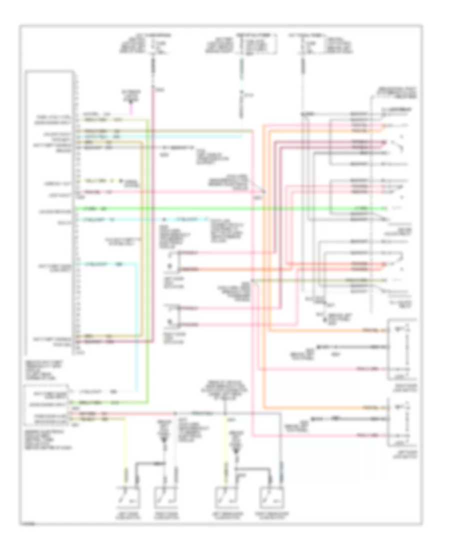
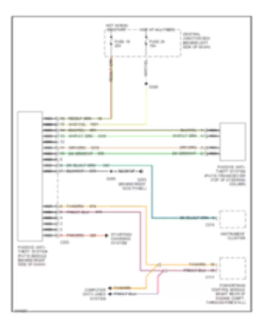
ANTI-THEFT Forced Entry Wiring Diagram for Ford Ranger 2000 List of elements for Forced Entry Wiring Diagram for Ford Ranger 2000: 64 (behind dash, right of steering column) relay box (behind left kick panel) g200 (dlc) in (main harn, near breakout for generic electronic module) (rear of vehicle, near breakout for black 8-pin connector, under left rear of vehicle) All lock relay All unlock relay Anti-theft disable Anti-theft door ajar input Battery junction box (left rear of engine compt) C221 C222 C409 C410 Central juntion box (behind left side of dash) Data link connector (dlc) (fastened to bottom of dash, near steering column) Door disarm input Driver unlock relay Drvr door ajar Exterior lights system Fuel sys/ anti-theft mini fuse 9 20a Fuse 15a Fuse 7.5a G108 (left side of upper radiator support) G200 (behind left kick panel) Generic electronic module (gem)/ central timer module (ctm) (behind center of dash) Ground Horn rly out Horns system Hot at all times Hot in acc or run Left door ajar switch Left door lock actuator Left door lock switch Left rear door ajar switch Lock Lock in/out Park lp rly ctrl Pass door ajar Pwr (bat) Pwr (ign) Remote anti-theft personality (rap) module (in left rear corner of cab) Right door ajar switch Right door lock actuator Right door lock switch Right rear door ajar switch S116 S200 (main harn, near breakout for passenger air bag) S201 S205 S225 (main harn, near breakout for generic electronic module) S238 S244 S270 (main harn, near breakout to generic electronic module) S271 S280 S300 S401 S500 S600 Unlk Unlock drv's dr Unlock in/out W/o anti-theft system only Passive Anti-theft Wiring Diagram for Ford Ranger 2000 List of elements for Passive Anti-theft Wiring Diagram for Ford Ranger 2000: 18 C111 C214 C255 Central junction box (behind left side of dash) Computer data lines system Fuse 19 25a Fuse 26 10a G203 (behind right kick panel) Hot at all times Hot in run or start Instrument cluster Nca Passive anti- theft system (pats) module (behind right side of dash) Passive anti- theft system (pats) transceiver (top of steering column) Powertrain control module (right rear of engine compt, through firewall) S205 S260 Starting/ charging system
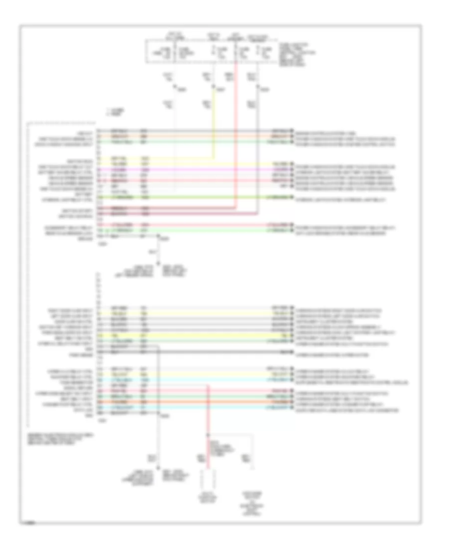
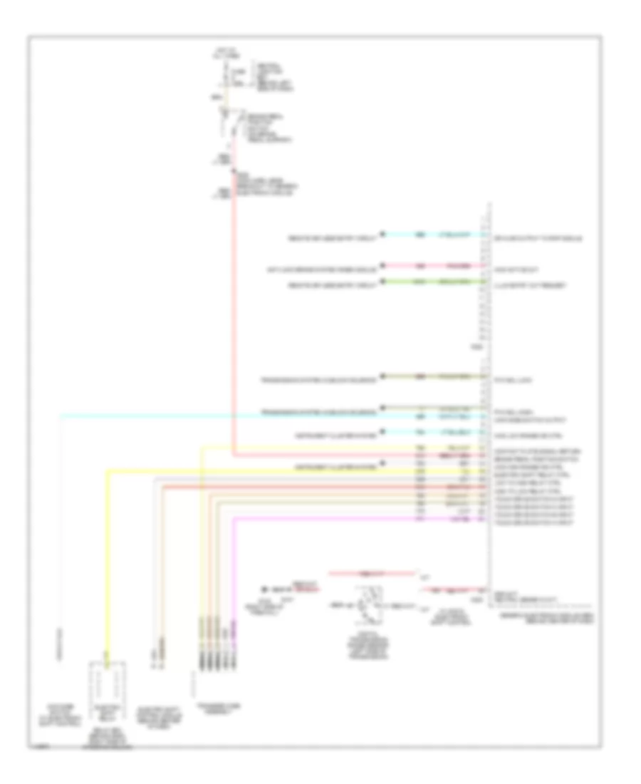
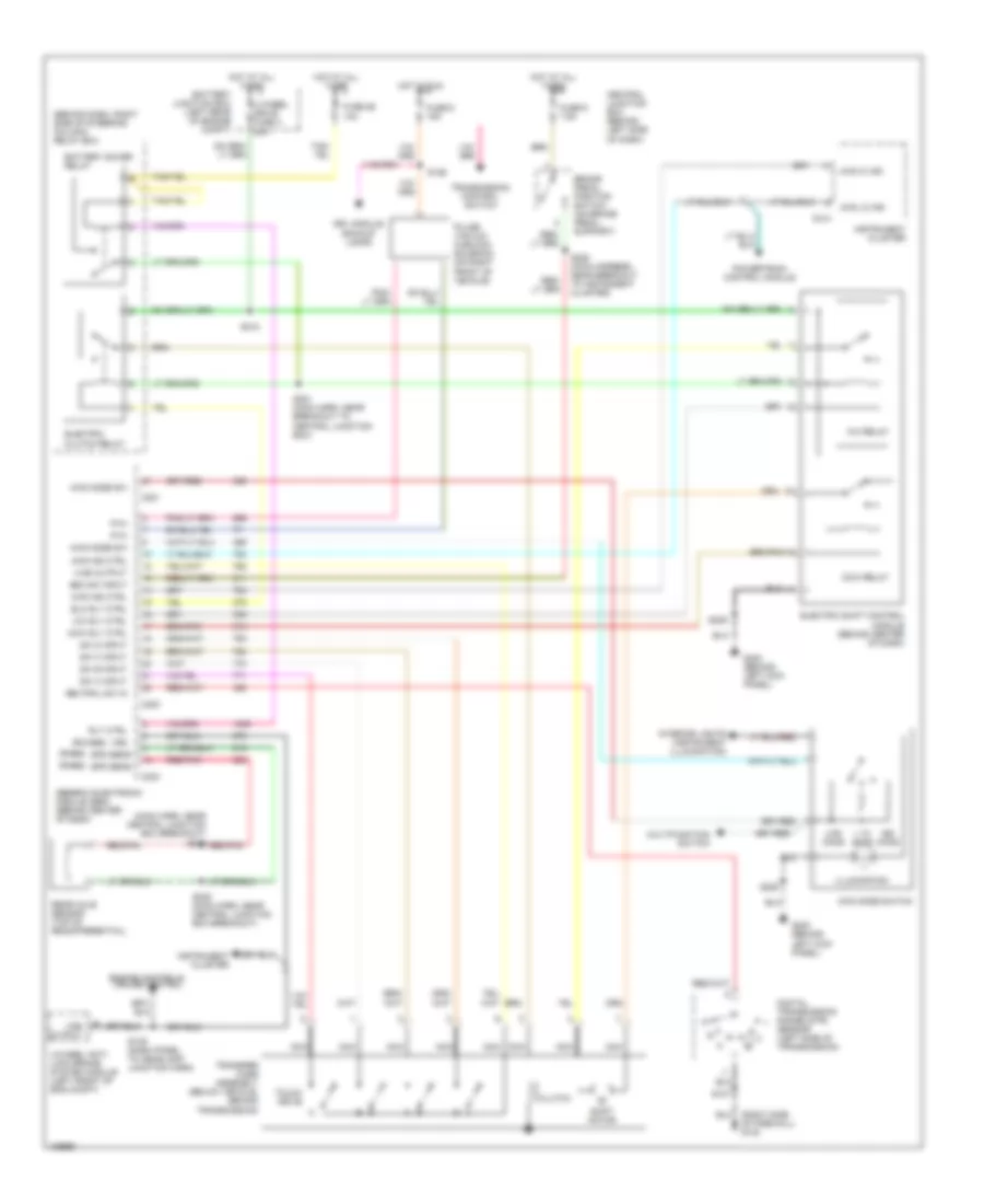
BODY COMPUTER Body Computer Wiring Diagrams (1 of 2) for Ford Ranger 2000 List of elements for Body Computer Wiring Diagrams (1 of 2) for Ford Ranger 2000: 79 (1999) (2000) 4wabs rabs 4wd mode switch (w/ electronic shift control) Accessory delay relay Anti-lock brakes system (rear axle sensor) Battery Battery saver relay ctrl C221 C224 Computer data lines system (data link connector) Data link Door ajar ind ctrl Down window command input Engine controls system (vehicle speed sensor) Engine controls system (vss) Fuse 10a Fuse 7.5a Fuse junction panel central junction box (behind left side of dash) G101 (left side of upper radiator suppoert) G103 (top center of left fender apron) G200 (behind left kick panel) G201 (behind right kick panel) Generic electronic module (gem)/ central timer module (ctm) (behind center of dash) Gnd Ground Hot at all times Hot in acc or run Hot in run Hot in start Ignition (acc/run) Ignition (run) Ignition (start) Ignition key warning input Instrument cluster system Interior lamp relay ctrl Interior lights system (battery saver relay) Interior lights system (interior lamp relay) Interval delay/wash input Left door ajar input Multi- function switch One touch down relay out One touch down sense (hi) One touch down sense (lo) Park sense Park/headlamps on input Power windows system (accessory delay relay) Power windows system (master control switch) Power windows system (one touch down module) Rear axle sensor (low) Red/pnk Right door ajar input Run/park relay ctrl S205 S209 S215 (main harn, in breakout to gem) S227 S238 S260 Seat belt ind ctrl Seat belt input Signal return Tan/red Tone generator Vehicle speed sensor Vss out Warning systems (clock spring assembly) Warning systems (left door ajar switch) Warning systems (main light sw/park lamp relay) Warning systems (right door ajar switch) Warning systems (seat belt switch) Washer pump relay ctrl Wiper hi-lo relay ctrl Wiper mode select sw input Wiper/washer system (hi/low relay) Wiper/washer system (multi-function switch) Wiper/washer system (run/park relay) Wiper/washer system (washer pump relay) Wiper/washer system (wiper motor) Body Computer Wiring Diagrams (2 of 2) for Ford Ranger 2000 List of elements for Body Computer Wiring Diagrams (2 of 2) for Ford Ranger 2000: 42 4wd active out 4wd high range ind ctrl 4wd low range ind ctrl 4wd mode switch (w/ electronic shift control) 4wd mode switch output A/t Anti-lock brake system (rabs module) Brake pedal position switch Brake pedal position switch (on brake pedal support) C222 C223 Central junction box (behind left side of dash) Contact plate signal return Digital transmission range sensor (left side of transmission) Dr ajar output to rap module Electric shift control module (behind center of dash) Electric shift relay Electric shift relay ctrl Fuse 7.5a G123 (right side of firewall) Generic electronic module (gem) (behind center of dash) Gnd (m/t) neutral sense in (a/t) High to low relay ctrl Hot at all times Illum entry out request Instrument cluster system Low to high relay ctrl M/t Nca Pvh sol (high) Pvh sol (low) Relay box (behind dash, right side of steering column) Remote keyless entry circuit S107 S228 (main harn, near breakout to generic electronic module) Touch drive switch a input Touch drive switch b input Touch drive switch c input Touch drive switch d input Transfer case assembly Transmission system (hublock solenoid) W/ 4wd & electronic shift control
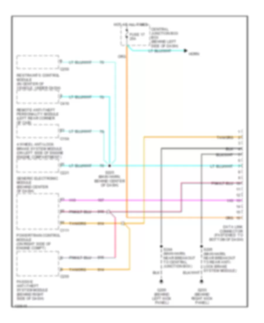
COMPUTER DATA LINES Computer Data Lines for Ford Ranger 2000 List of elements for Computer Data Lines for Ford Ranger 2000: 21 4 wheel anti-lock brake system module (on left side of engine engine compartment) C111 C154 C221 C250 C255 C410 Central junction box box (behind left side of dash) Data link connector (fastened to bottom of dash) Fuse 17 25a G200 (behind left kick panel) G203 (behind right kick panel) Generic electronic module (behind center of dash) Horn Hot at all times Passive anti-theft system module (behind right side of dash) Powertrain control module (on right side of engine compt) Remote anti-theft personality module (left rear corner of cab) Restraints control module (in center of vehicle, under dash) S225 (main harn, behind center of dash) S244 (main harn, near breakout to central junction box)
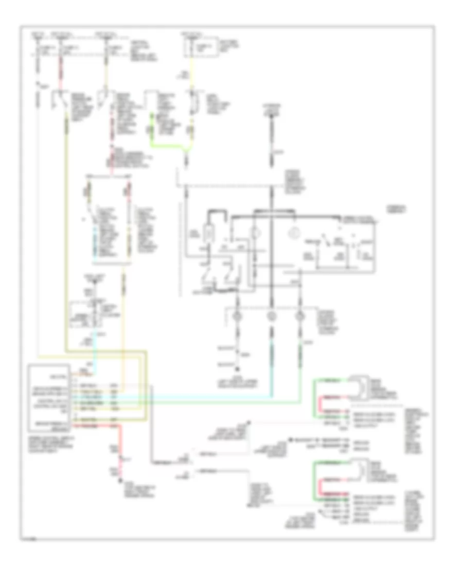
CRUISE CONTROL Cruise Control Wiring Diagram for Ford Ranger 2000 List of elements for Cruise Control Wiring Diagram for Ford Ranger 2000: 66 (dash to headlamp harn, left side of eng compt) s139 20a 4 wheel anti-lock brake system (4wabs) module (on left front of engine compt) 7.5a A/t Accel Air bag sliding assembly contact (steering column) Air bag sliding contact (top of steering column) Battery junction box Brake pedal position (bpp) switch (behind left side of dash, on brake pedal support) Brake press in Brake pressure switch (left rear of engine compart- ment) C154 C214 C219 C221 C224 C409 Central junction box (behind left side of dash) Clutch pedal position (cpp) switch (behind left side of dash, top of clutch pedal support) Clutch pedal position (cpp) switch jumper (behind dash, left of steering column) Coast Control sw gnd Control sw in Fuse 10 Fuse 10 15a Fuse 13 Fuse 9 G104 (top center of left front fender apron) G105 (top center of right front fender apron) G108 (left side of upper radiator support) Generic electronic module (gem)/ center timer module (ctm) (behind center of dash) Ground Horn relay (in battery junction panel) Horn switches Hot at all times Hot in run Ign Ind ctrl Instru- ment cluster Interior lights system M/t Main light switch Nca Off Ohms Rear axle sen (high) Rear axle sen (low) Rear axle sensor (top of rear differential) Red/pnk Remote anti- theft person- ality (rap) module (left rear corner of cab) Resume S117 S139 (dash to head- lamp harn, left side of eng compt) S205 S227 S228 (main harness, near breakout to transmission control switch) Set/ Speed control ind Speed control servo/ amplifier assembly (right rear of engine compartment) Speed control switch assembly Steering assembly Vehicle speed in Vss output W/ 4wabs W/ rabs
ENGINE PERFORMANCE
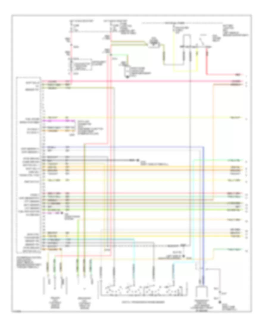
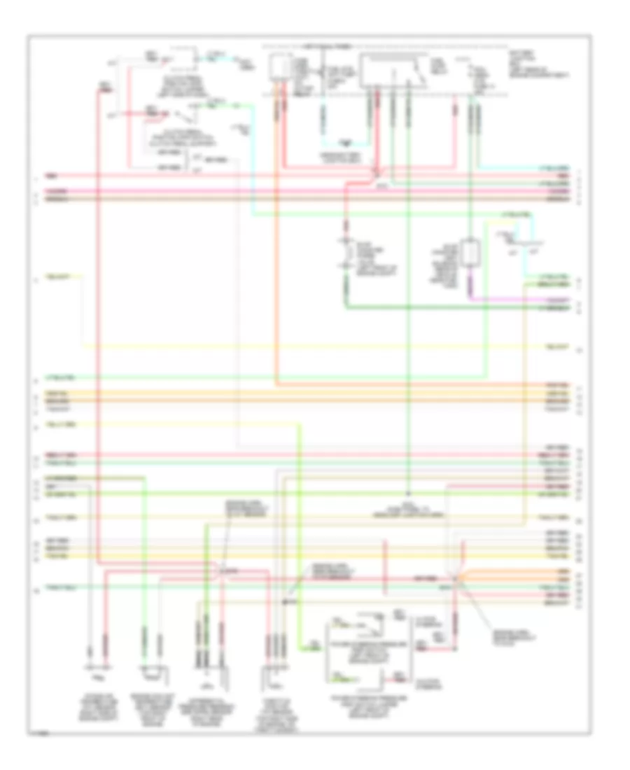
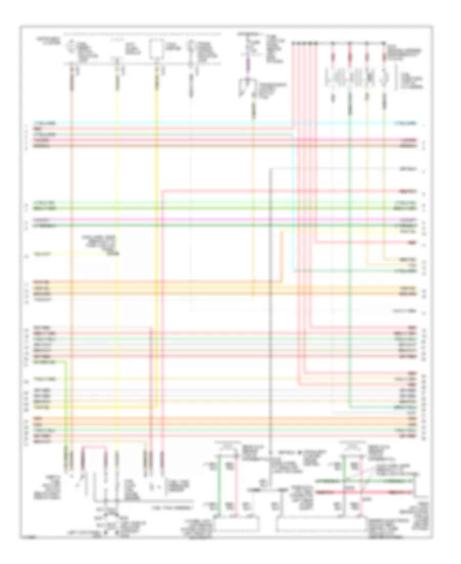
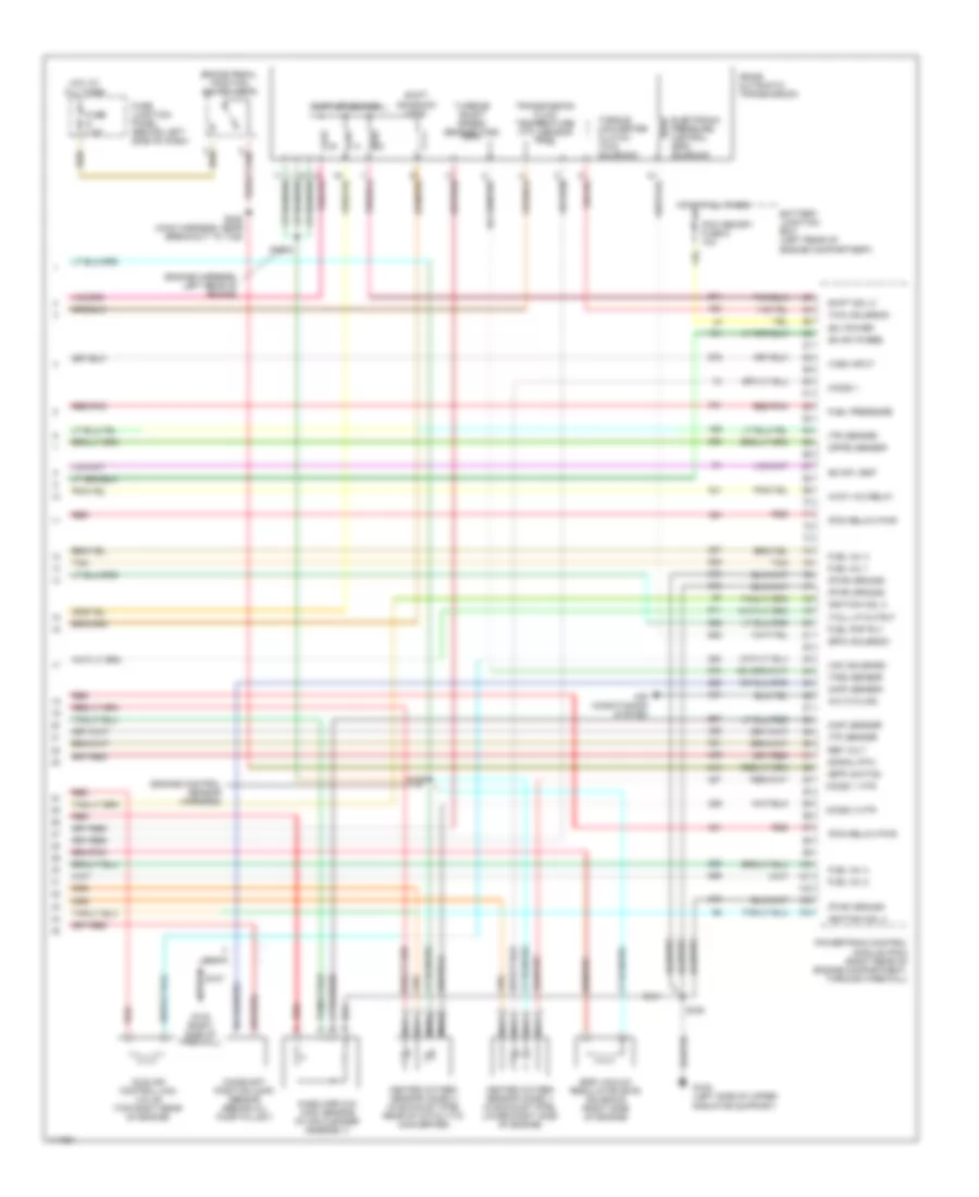
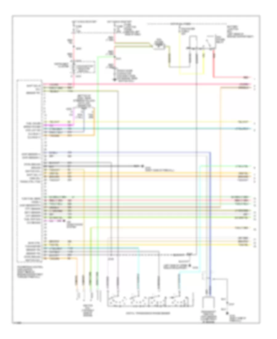
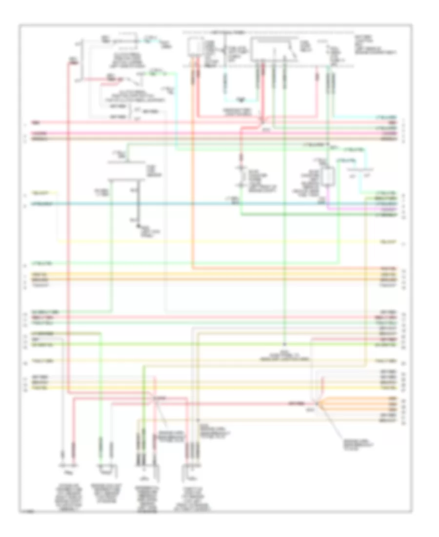
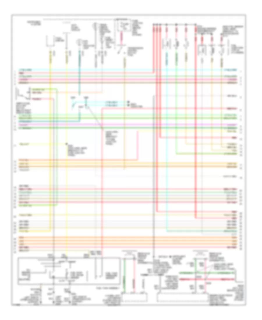
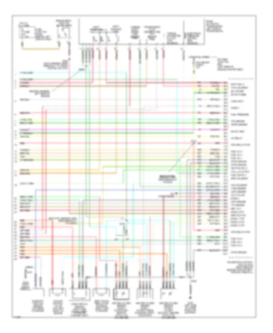
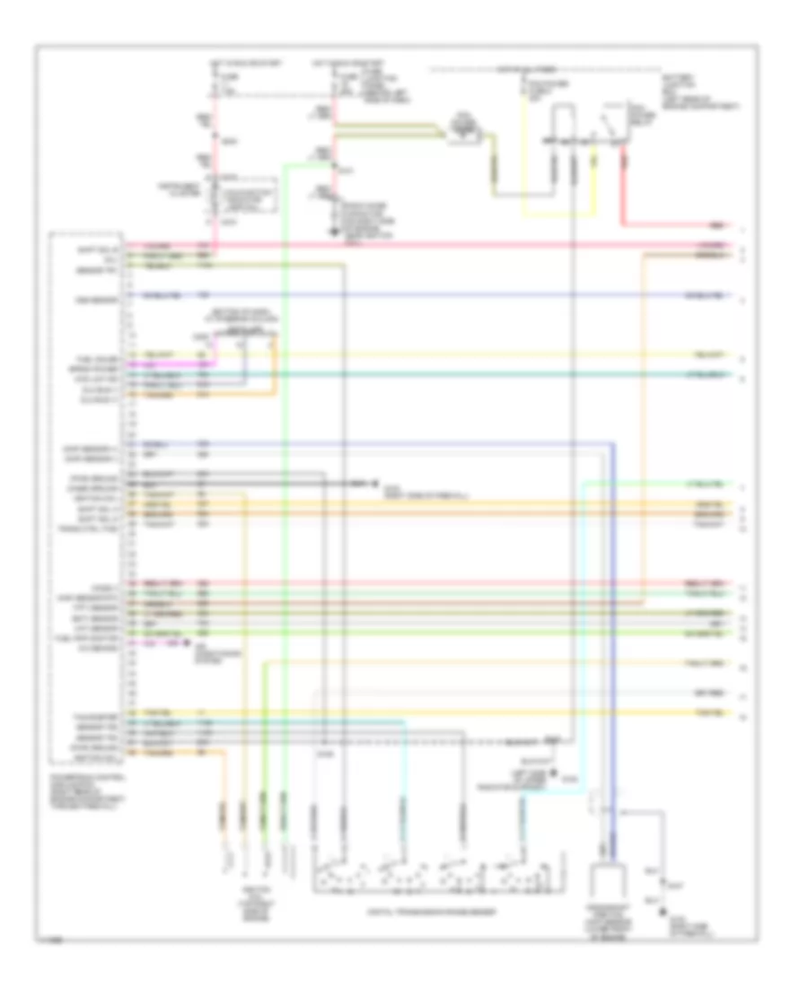
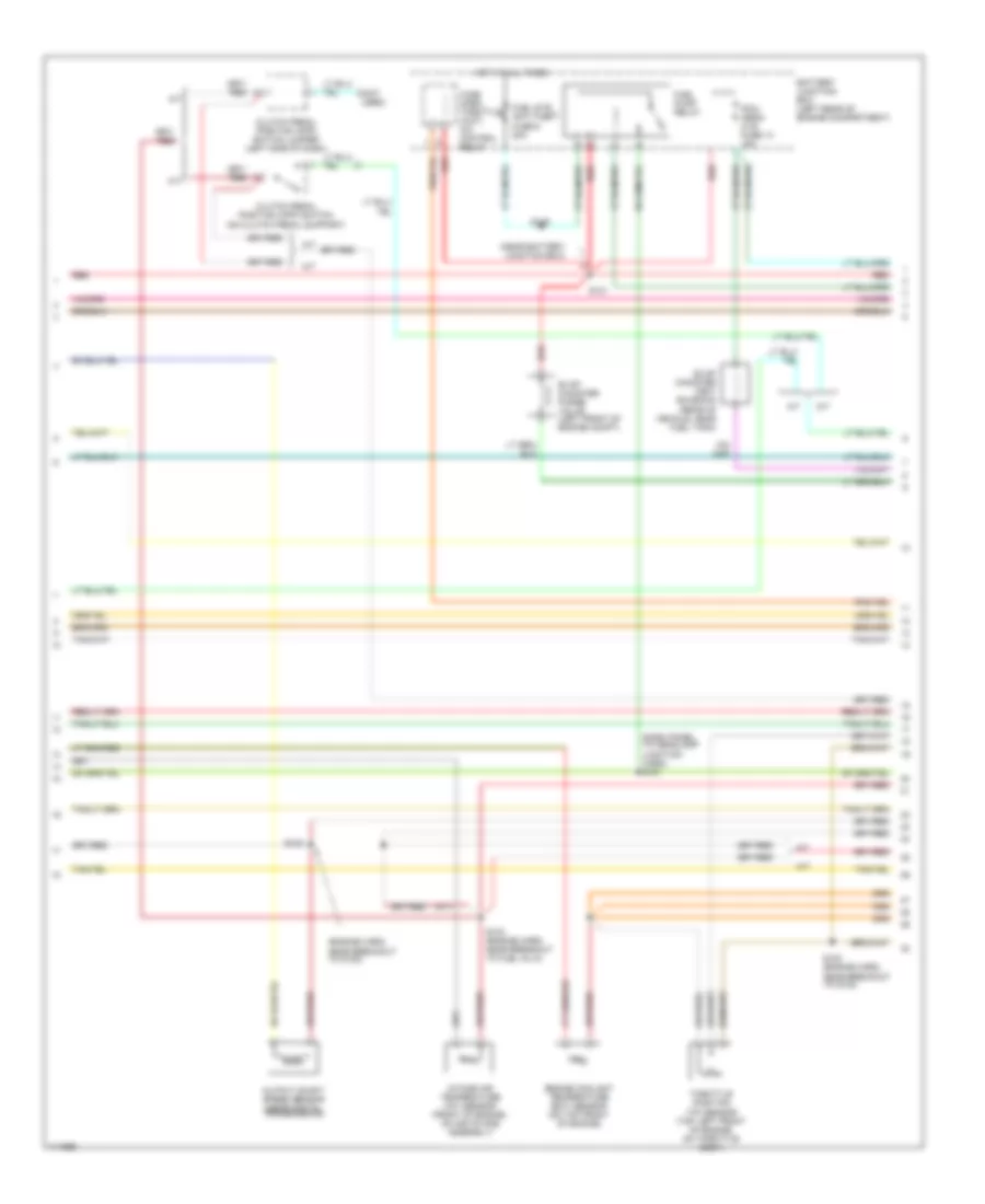
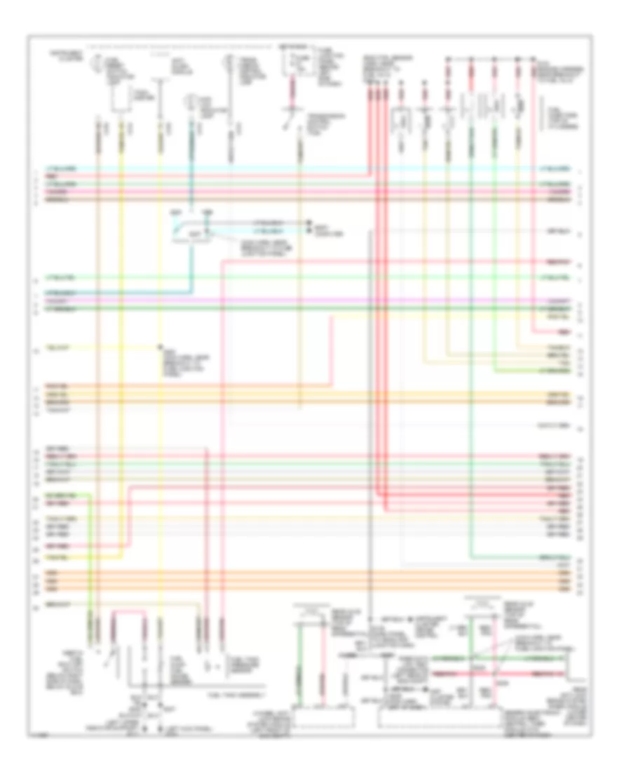
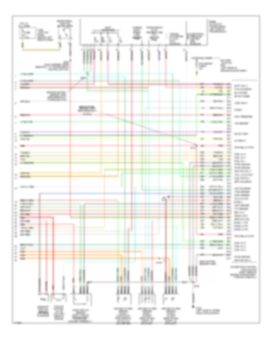
2.5L 2.5L, Engine Performance Wiring Diagrams (1 of 4) for Ford Ranger 2000 List of elements for 2.5L, Engine Performance Wiring Diagrams (1 of 4) for Ford Ranger 2000: 58 (case) ground (ckp) sensor (+) (ckp) sensor (-) (css) sol (ect) sensor (evr) ctrl (ho2s) 3 (iat) sensor (left side of radiator support) (maf) sensor rtn (psp) switch (pwr) ground (tft) sensor A/c demand Air conditioning system Battery junction box (left rear of engine compartment) C209 C215 Crankshaft position (ckp) sensor (lower right front of engine) Data link connector (dlc) (fastened to bottom of dash near steering column) Digital transmission range sensor Dlc bus (+) Dlc bus (-) Eprom pwr feed Fuel gauge Fuel pmp monitor Fuse 25a Fuse 7.5a Fuse junction panel (behind left side of dash) G108 G123 (right side of firewall) Hot at all times Hot in run or start Ignition coil 1 Ignition coil 2 Instrument cluster Malfunction indicator lamp (mil) Mil Pcm power diode Pcm power fuse 8 30a Pcm power relay Powertrain control module (pcm) (right rear of engine compartment, through firewall) Primary coil (top right side of engine) Radio noise capacitor (near secondary coil) Red S101 S106 S107 S118 S240 Secondary coil (top right front of engine) Sensor tr1 Sensor tr2 Sensor tr4 Shift sol a Shift sol b Tachometer Trans ctrl (tcs) 2.5L, Engine Performance Wiring Diagrams (2 of 4) for Ford Ranger 2000 List of elements for 2.5L, Engine Performance Wiring Diagrams (2 of 4) for Ford Ranger 2000: 35 (engine harn, near breakout to g123) (engine harn, near breakout to iat sensor) (engine harn, near breakout to tp sensor) (near battery junction box) (not used) A/t A/t Battery junction box (left rear of engine compartment) Clutch pedal position (cpp) switch (clutch pedal support) Clutch pedal position (cpp) switch jumper (left side of dash) Differential pressure feedback egr (dpfe) sensor (right rear of engine) Engine coolant temperature (ect) sensor (top right front of engine) Evap canister purge valve (left front of engine compt) Evap canister vent solenoid (rear of vehicle, near fuel tank) Fuel pump relay Fuel sys/ anti-theft fuse 9 20a Hot at all times Intake air temperature (iat) sensor (right side of engine compt) M/t M/t Nca Pcm/ hego/ cvs fuse 13 15a Power steering pressure (psp) switch (left front of engine compt) Power steering pressure (psp) switch jumper (left front of engine compt) Red S100 S102 S103 S116 S121 S151 (dash panel to headlamp junction harn) Throttle position (tp) sensor (top right side of engine, on throttle body) W/ pwr steering W/o pwr steering Wide open throttle (wot) a/c cutoff relay 2.5L, Engine Performance Wiring Diagrams (3 of 4) for Ford Ranger 2000 List of elements for 2.5L, Engine Performance Wiring Diagrams (3 of 4) for Ford Ranger 2000: 39 (left kick panel) g200 (left side of radiator support) g108 (main harn, near breakout to fuse junction panel) (main harn, near breakout to fuse junction panel) s253 4-wheel anti- lock brake system module (left front of eng compt) 4wabs Anti- slosh module C214 C215 Connector (left rear of eng compt) Fuel injectors (top of cylinders) Fuel pump/ fuel gauge sender Fuel reset switch indicator lamp Fuel tank assembly Fuel tank pressure sensor Fuse 15a Fuse junction panel (behind left side of dash) Generic electronic module (gem)/ central timer module (ctm) (center of dash) Hot in run Inertia fuel shut-off switch (below right side of dash) Instrument cluster Instrument cluster, cruise control Rabs Rabs data link test red/pnk Rear anti-lock brake system module (lower center of dash) Rear axle sensor (top of differential) Red Red/ pnk Red/pnk S104 (engine harness, near breakout to g123) S139 (dash panel to headlamp junction harn) S205 S235 S236 S307 Tach- ometer Tan Trans- mission control indicator lamp Transmission control switch (tcs) 2.5L, Engine Performance Wiring Diagrams (4 of 4) for Ford Ranger 2000 List of elements for 2.5L, Engine Performance Wiring Diagrams (4 of 4) for Ford Ranger 2000: 67 (b+) power (bpp) switch (cmp) sensor (dpfe) sensor (engine control sensor harness) (engine harness, left rear of engine) (epc) solenoid (evap) purge (evap) vent (ho2s) 1 (ho2s) 1 htr (ho2s) 3 htr (iac) solenoid (maf) sensor (pcm relay) pwr (pwr) ground (tcc) solenoid (tcil) lp output (tp) sensor (tr) sensor (tss) sensor (vss) input (wot) a/c relay 4r44e automatic transmission A/c cycling Air conditioning system Battery junction box (left rear of engine compartment) Brake pedal position switch (bpp) Camshaft position (cmp) sensor (behind oil pump pulley) Egr vacuum regulator (evr) solenoid (right side of engine) Electronic pressure control (epc) solenoid Fuel inj 1 Fuel inj 2 Fuel inj 3 Fuel inj 4 Fuel pmp rly Fuel pressure Fuse 7.5a Fuse junction panel (behind left side of dash) G108 (left side of upper radiator support) G123 (right side of firewall) Heated oxygen sensor (ho2s) 1 (in exhaust pipe, lower right side of engine) Heated oxygen sensor (ho2s) 3 (in exhaust pipe, rear of catalytic converter) Hot at all times Idle air control (iac) valve (top right rear of engine) Ignition coil 3 Ignition coil 4 Mass airflow (maf) sensor (in air cleaner assembly) Nca Pcm memory fuse 6 10a Powertrain control module (pcm) (right rear of engine compartment, through firewall) Red Red/pnk Ref volt S1002 S106 S107 S109 S228 (main harness, near breakout to tcs) Shift sol c Shift solenoid (css) Shift solenoids Signal rtn Tan Torque converter clutch (tcc) solenoid Transmission fluid temperature (tft) sensor Turbine shaft speed sensor (tss)
3.0L 3.0L, Engine Performance Wiring Diagrams (1 of 4) for Ford Ranger 2000 List of elements for 3.0L, Engine Performance Wiring Diagrams (1 of 4) for Ford Ranger 2000: 57 (bottom of dash, near steering column) data link connector (dlc) (ckp) sensor (+) (ckp) sensor (-) (css) sol (ect) sensor (evr) ctrl (ho2s) 3 (iat) sensor (left side of upper radiator support) (maf) sensor rtn (mil) (pwr) ground (tft) sensor 4wd low ind A/c demand Air conditioning system Battery junction box (left rear of engine compartment) C209 C215 Crankshaft position (ckp) sensor (lower front of engine) Digital transmission range sensor Dlc bus (+) Dlc bus (-) Eprom power Flex fuel sens Fuel gauge Fuel pmp mon Fuse 25a Fuse 7.5a Fuse junction panel (behind left side of dash) G108 G123 (right side of firewall) Ground Hot at all times Hot in run or start Ignition coil Ignition coil (top right side of engine) Instrument cluster Malfunction indicator lamp (mil) Pcm power diode Pcm power fuse 8 30a Pcm power relay Powertrain control module (pcm) (right rear of engine compartment, through firewall) Radio noise capacitor (on right side of engine, near ignition coil) Red S101 S106 S107 S118 S240 Sensor tr1 Sensor tr2 Sensor tr4 Shift sol a Shift sol b Tachometer Trans ctrl (tcs) 3.0L, Engine Performance Wiring Diagrams (2 of 4) for Ford Ranger 2000 List of elements for 3.0L, Engine Performance Wiring Diagrams (2 of 4) for Ford Ranger 2000: 34 (engine harn, near breakout to fuel inj 6) (engine harn, near breakout to g123) (near battery junction box) (not used) (top of clutch pedal support) A/t A/t Battery junction box (left rear of engine compartment) Clutch pedal position (cpp) switch Clutch pedal position (cpp) switch jumper (left side of dash) Differential pressure feedback egr (dpfe) sensor (left side of engine) Engine coolant temperature (ect) sensor (top front of engine) Evap canister purge valve (left front of engine compt) Evap canister vent solenoid (rear of vehicle, near fuel tank) Flex fuel sensor Fuel pump relay Fuel sys/ anti-theft fuse 9 20a G200 (left kick panel) Hot at all times Intake air temperature (iat) sensor (right side of engine compt, on air intake assembly) M/t M/t Nca Pcm/ hego/ cvs fuse 13 15a Red S100 (engine harn, near breakout to fuel inj 5) S102 S103 S116 S121 S151 (dash panel to headlamp junction harn) S311 Throttle position (tp) sensor (top left front of engine, on throttle body) Wide open throttle (wot) a/c cutoff relay 3.0L, Engine Performance Wiring Diagrams (3 of 4) for Ford Ranger 2000 List of elements for 3.0L, Engine Performance Wiring Diagrams (3 of 4) for Ford Ranger 2000: 47 (eng ctrl sensor harn, near breakout to evr solenoid) s113 red (left kick panel) g200 (left side of upper radiator support) g108 (main harn, near breakout to fuse junct panel) (main harn, near breakout to fuse junction panel) 4 wheel anti- lock brake system module (left front of eng compt) 4wabs 4wd low indicator lamp Anti- slosh module Body computer C214 C215 Connector (left rear of engine compartment) Ffv sender module (if equipped) Fuel injectors (top of cylinders) Fuel pump/ fuel gauge sender Fuel reset switch ind lamp Fuel tank assembly Fuel tank pressure sensor Fuse 15a Fuse junction panel (behind left side of dash) Generic electronic module (gem)/ central timer module (ctm) (center of dash) Hot in run Inertia fuel shut-off switch (below right side of dash) Instrument cluster Instrument cluster, cruise control Rabs Rabs data link test red/pnk Rear anti-lock brake system module (lower center of dash) Rear axle sensor (top of rear differential) Red Red/ pnk Red/pnk S104 red (engine harness, near breakout to fuel inj 6) S139 (dash panel to headlamp junction harn, left side of eng compt) S235 S236 S237 S253 (main harn, near breakout to fuse junction panel) S254 S307 Tach- ometer Tan Trans- mission control indicator lamp Transmission control switch (tcs) W/ ff W/o ff 3.0L, Engine Performance Wiring Diagrams (4 of 4) for Ford Ranger 2000 List of elements for 3.0L, Engine Performance Wiring Diagrams (4 of 4) for Ford Ranger 2000: 75 (b+) power (bpp) switch (cmp) sensor (dpfe) sensor (eng control sensor harn, near breakout to g123) (eng ctrl sensor harn, near breakout to ho2s 2) (engine harness, left rear of engine) (epc) solenoid (evap) purge (evap) vent (ho2s) 1 (ho2s) 1 htr (ho2s) 2 (ho2s) 2 htr (ho2s) 3 htr (iac) solenoid (maf) sensor (pcm relay) pwr (pwr) ground (tcc) solenoid (tcil) lp output (tp) sensor (tr) sensor (tss) sensor (vss) input 4r44e automatic transmission (left side of transmission) A/c cycling A/c relay A/t Air conditioning Battery junction box (left rear of engine compartment) Brake pedal position switch (bpp) Camshaft position sensor (top rear of engine) Egr vacuum regulator solenoid (right side of engine) Electronic pressure control (epc) solenoid Fuel inj 1 Fuel inj 2 Fuel inj 3 Fuel inj 4 Fuel inj 5 Fuel inj 6 Fuel pmp rly Fuel pressure Fuse 7.5a Fuse junction panel (behind left side of dash) G108 (left side of upper radiator support) G123 (right side of firewall) Heated oxygen sensor (ho2s) 1 (in right rear of engine compt, in exhaust) Heated oxygen sensor (ho2s) 2 (in left exhaust, before catalytic converter) Heated oxygen sensor (ho2s) 3 (in exhaust, rear of catalytic converter) Hot at all times Idle air control valve (top left front of engine) Ignition coil 2 M/t Mass airflow sensor (right side of eng compt, within air cleaner assy) Nca Pcm memory fuse 6 10a Powertrain control module (pcm) (right rear of engine compartment, through firewall) Red Red/pnk Ref volt S1002 S106 S107 S109 S112 S228 (main harness, near breakout to trans control switch) Shift sol c Shift solenoid (css) Shift solenoids Signal rtn Tan Torque converter clutch (tcc) solenoid Transmission fluid temperature (tft) sensor Turbine shaft speed (tss) sensor
4.0L 4.0L, Engine Performance Wiring Diagrams (1 of 4) for Ford Ranger 2000 List of elements for 4.0L, Engine Performance Wiring Diagrams (1 of 4) for Ford Ranger 2000: 57 (bottom of dash, at steering column) (case) ground (ckp) sensor (+) (ckp) sensor (-) (ect) sensor (ho2s) 3 (iat) sensor (left side of upper radiator support) (maf) sensor rtn (mil) (pwr) ground (tft) sensor 4wd low ind A/c demand Air conditioning system Battery junction box (left rear of engine compartment) C209 C215 Crankshaft position (ckp) sensor (lower front of engine) Data link connector (dlc) Digital transmission range sensor Dlc bus (+) Dlc bus (-) Eprom power Fuel gauge Fuel pmp monitor Fuse 25a Fuse 7.5a Fuse junction panel (behind left side of dash) G108 G123 (right side of firewall) Hot at all times Hot in run or start Ignition coil Ignition coil (top right side of engine) Instrument cluster Malfunction indicator lamp (mil) Oss sensor Pcm power diode Pcm power fuse 8 30a Pcm power relay Powertrain control module (pcm) (right rear of engine compartment, through firewall) Radio noise capacitor (on right side of engine, near ignition coil) Red S101 S106 S107 S118 S240 Sensor tr1 Sensor tr2 Sensor tr4 Shift sol a Shift sol b Shift sol d Tachometer Trans ctrl (tcs) 4.0L, Engine Performance Wiring Diagrams (2 of 4) for Ford Ranger 2000 List of elements for 4.0L, Engine Performance Wiring Diagrams (2 of 4) for Ford Ranger 2000: 29 (a/t) (dash panel to headlamp junction harn) s151 (engine harn, near breakout to g123) (near battery junction box) (not used) A/t A/t Battery junction box (left rear of engine compartment) Clutch pedal position (cpp) switch (on clutch pedal support) Clutch pedal position (cpp) switch jumper (left side of dash) Engine coolant temperature (ect) sensor (on top front of engine) Evap canister purge valve (left front of engine compt) Evap canister vent solenoid (rear of vehicle, near fuel tank) Fuel pump relay Fuel sys/ anti-theft fuse 9 20a Hot at all times Intake air temperature (iat) sensor (front of engine, on air intake assembly) M/t M/t Output shaft speed sensor (near digital transmission) Pcm/ hego/ cvs fuse 13 15a Red S100 (engine harn, near breakout to g123) S102 S103 (engine harn, near breakout to fuel inj 5) S116 S121 Throttle position (tp) sensor (top left front of engine, on throttle body) Wide open throttle (wot) a/c control relay 4.0L, Engine Performance Wiring Diagrams (3 of 4) for Ford Ranger 2000 List of elements for 4.0L, Engine Performance Wiring Diagrams (3 of 4) for Ford Ranger 2000: 44 (eng ctrl sensor harn, near breakout to fuel inj 2) s113 (left kick panel) g200 (left upper radiator support) g111 (main harn, near breakout to fuse junction panel) 4-wheel anti- lock brake system module (left front of eng compt) 4wabs 4wd low indicator lamp Anti- slosh module Body computer C214 C215 Fuel injectors (top of cylinders) Fuel pump/ fuel gauge sender Fuel reset switch indicator lamp Fuel tank assembly Fuel tank pressure sensor Fuse 15a Fuse junction panel (behind left side of dash) Generic electronic module (gem)/ central timer module (ctm) (center of dash) Hot in run Inertia fuel shut-off switch (below right side of dash, below glove box) Inst cluster system Instrument cluster Instrument cluster, cruise control Link test connector (left rear of eng compt) Rabs Rear anti-lock brake system (rabs) module (lower center of dash) Rear axle sensor (top of rear differential) Red Red/ pnk Red/pnk S104 (engine harness, near breakout to fuel inj 5) S139 (dash panel to headlamp junction harn) S205 S229 S235 S236 S237 S253 (main harn, near breakout to fuse junction panel) S307 Tach- ometer Tan Trans- mission control indicator lamp Transmission control switch (tcs) 4.0L, Engine Performance Wiring Diagrams (4 of 4) for Ford Ranger 2000 List of elements for 4.0L, Engine Performance Wiring Diagrams (4 of 4) for Ford Ranger 2000: 70 (b+) power (bpp) switch (cmp) sensor (eng control sensor harn) (eng control sensor harn, near breakout (engine control sensor harn, near breakout to ground g123) (epc) solenoid (evap) purge (evap) vent (ho2s) 1 (ho2s) 1 htr (ho2s) 2 (ho2s) 2 htr (ho2s) 3 htr (iac) solenoid (maf) sensor (pcm relay) pwr (pwr) ground (tcc) solenoid (tcil) lp output (tp) sensor (tr) sensor (tss) sensor (vss) input 5r55e automatic transmission (left side of transmission) A/c cycling A/c relay A/c sys Battery junction box (left rear of engine compartment) Brake pedal position switch (bpp) Camshaft position sensor (top rear of engine) Electronic pressure control (epc) solenoid Fuel inj 1 Fuel inj 2 Fuel inj 3 Fuel inj 4 Fuel inj 5 Fuel inj 6 Fuel pmp rly Fuel pressure Fuse 7.5a Fuse junction panel (behind left side of dash) G108 (left side of upper radiator support) Heated oxygen sensor (ho2s) 1 (in right rear of eng compt, in exhaust) Heated oxygen sensor (ho2s) 2 (in left rear of eng compt, in exhaust) Heated oxygen sensor (ho2s) 3 (in exhaust pipe, rear of catalytic converter) Hot at all times Idle air control valve (top left rear of engine) Ignition coil 3 Ignition coil 4 Mass airflow sensor (right side of engine compt, within air cleaner assembly) Nca Pcm memory fuse 6 10a Powertrain control module (pcm) (right rear of engine compartment, through firewall) Red Red/pnk Ref volt S1001 S106 S109 S112 S228 (main harness, near breakout to transmission control switch) Shift sol 3 Shift solenoids Signal rtn Tan To pcm) Torque converter clutch (tcc) solenoid Transmission fluid temperature (tft) sensor Turbine shaft speed (tss) sensor
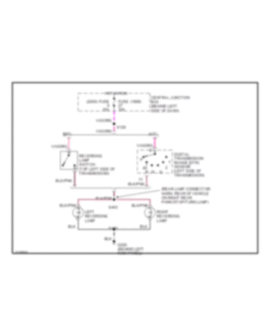
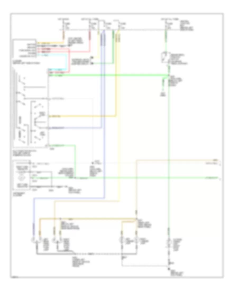
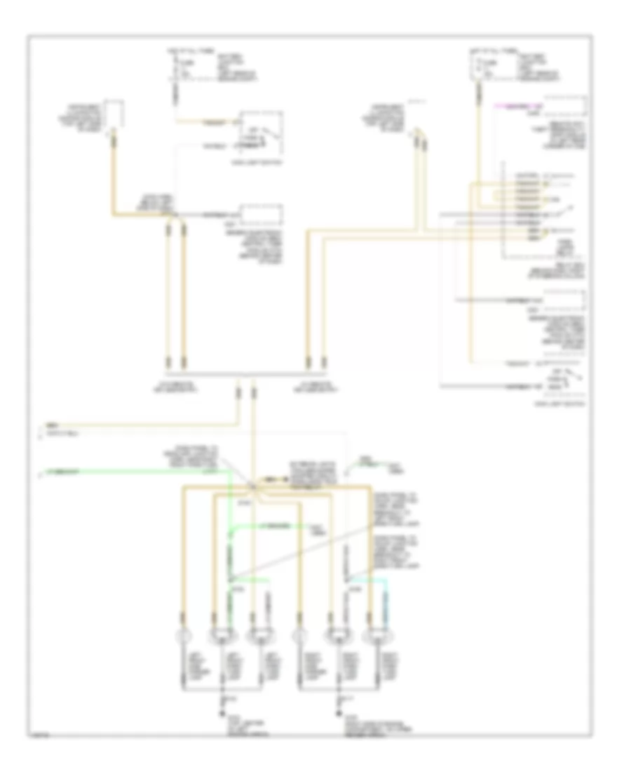
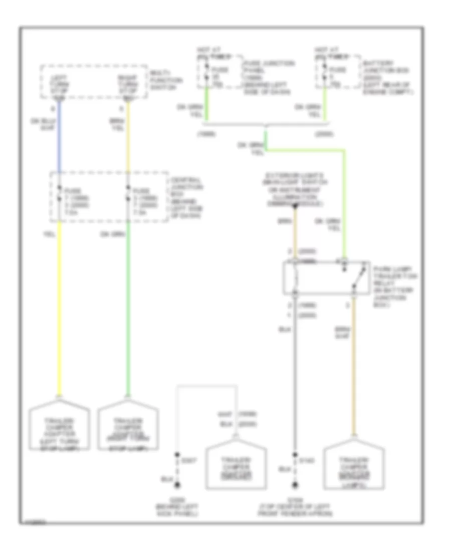
EXTERIOR LIGHTS Back-up Lamps Wiring Diagram for Ford Ranger 2000 List of elements for Back-up Lamps Wiring Diagram for Ford Ranger 2000: 16 (1999) (2000) (a/t) (m/t) (rear lamp connector harn, rear of vehicle on right rear park/stop/turn lamp) Central junction box (behind left side of dash) Digital transmission range (dtr) sensor (left side of transmission) Fuse 15a G200 (behind left kick panel) Hot in run Left reversing lamp Reversing lamp switch (top left side of transmission) Right reversing lamp S126 S400 S403 Exterior Lamps Wiring Diagram (1 of 2) for Ford Ranger 2000 List of elements for Exterior Lamps Wiring Diagram (1 of 2) for Ford Ranger 2000: 42 (main harn, behind dash, near steering column) s251 (not used) (top center of left front fender apron) g104 Brake pedal position switch (on brake pedal support) C214 C215 C253 Central junction box (behind left side of dash) Exterior lights (trailer/camper adapter circuit) Flasher (behind left side of dash) Fuse 15a Fuse 20a Fuse 7.5a G200 (behind left kick panel) Ground Hazard Hazard sw out Hot at all times Hot in run Ignition Instrument cluster Left license lamp Left rear park/ stop/ turn lamp Left turn Left turn indicator Multi-function switch (top left side of steering column) Normal Outside cargo/ high mount stop lamp Power Right license lamp Right rear park/ stop/ turn lamp Right turn Right turn indicator S131 S244 S252 (main harn, below left side of dash) S300 S307 S400 (under left rear of vehicle, near rear frame) S401 (below left rear of vehicle, near rear frame) S407 (rear lamp harn, behind rear wheel) Turn signal sw Exterior Lamps Wiring Diagram (2 of 2) for Ford Ranger 2000 List of elements for Exterior Lamps Wiring Diagram (2 of 2) for Ford Ranger 2000: 33 (dash panel to hdlmp junction harn, near breakout to left front park/turn lamp) (dash panel to hdlmp junction harn, near breakout to right front park/turn lamp) (dash panel to headlamp junction harn, near right front park/turn lamp) (main harn, below left side of dash) s272 (not used) (w/ remote keyless entry) (w/o remote keyless entry) Battery junction box (left rear of engine compt) C221 C409 Exterior lights (trailer/camper adapter circuit) (parklamps trlr tow relay) Fuse 15a G104 (top center of left fender apron) G105 (right side of engine compartment, on upper fender apron) Generic electronic module (gem)/ central timer module (ctm) (behind center of dash) Head Hot at all times Instrument illumination dimming module (top left side of dash) Left front park/ turn lamp Left front side marker lamp Main light switch Off Park Park lamps relay Relay box (behind dash, right of steering column) Remote anti- theft personality (rap) module (in left rear corner of cab) Right front park/ turn lamp Right front side marker lamp S117 S123 S130 S154 S155 Trailer/Camper Adapter Wiring Diagram for Ford Ranger 2000 List of elements for Trailer/Camper Adapter Wiring Diagram for Ford Ranger 2000: 23 (1999) (2000) 7.5a Battery junction box (2000) (left rear of engine compt) Central junction box (behind left side of dash) Exterior lights (main light switch or instrument illumination dimming module) Fuse (1999) (2000) Fuse 15a Fuse junction panel (1999) (behind left side of dash) G104 (top center of left front fender apron) G200 (behind left kick panel) Hot at all times Left turn/ stop sig Multi- function switch Park lamp/ trailer tow relay (in battery junction box) Right turn/ stop sig S143 S307 Stop lamp) Trailer/ camper adapter (ground) Trailer/ camper adapter (left turn/ stop lamp) Trailer/ camper adapter (right turn/ Trailer/ camper adapter (running lamps)
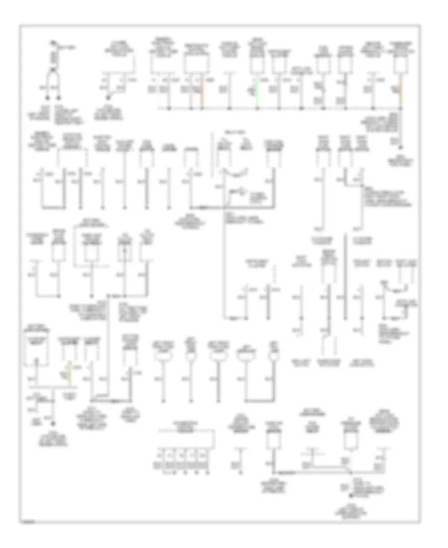
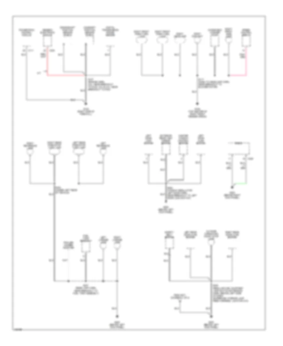
GROUND DISTRIBUTION Ground Distribution Wiring Diagram (1 of 2) for Ford Ranger 2000 List of elements for Ground Distribution Wiring Diagram (1 of 2) for Ford Ranger 2000: 86 (2.5l) engine coolant temperature sensor (not used) 4 wheel anti-lock brake system module 4wd mode switch A/c clutch diode A/c clutch field coil A/c pressure cutoff switch Air bag sliding contact All lock relay All unlock relay Auxiliary power socket 1 Battery Battery junction box Blend door actuator Brake fluid level switch Brake pedal position switch C150 C154 C214 C215 C216 C221 C224 C228 C233 C234 C238 C250 C409 Cigar lighter Data link connector Daytime running lamps module Electric shift control module Flasher relay Flex fuel vaporized sensor Foglight switch Fuel tank assembly Function selector switch assembly G100 (lower left front of engine compt, near battery) G104 (top center of left front fender apron) G108 (left side of upper radiator support) G110 (2.5l) (left front of engine) G203 (behind right kick panel) Generic electronic module/ central timer module Gnd Ignition switch Instrument cluster Left door ajar switch Left fog lamp Left front park/turn lamp Left front side lamp Left headlamp Main light switch Mass air flow sensor Parklamp/ trailer tow relay Passenger air bag deactivation switch Passive anti-theft system module Pcm power relay Powertrain control module Radio Rear anti-lock brake system module Rear anti-lock brake system proportioning valve switch assembly Relay box Remote anti-theft personality module Restraints control module (rcm) Right door ajar switch Right door lock switch S106 (engine harn, right side of firewall) S118 (dash to headlamp harn, near breakout to g108) S123 (dash to headlamp harn) S131 (dash to headlamp harn, in breakout near left side of firewall) S143 (dash to headlamp harn, in breakout to windshield wiper motor) S146 (alt rectifier sys harn, top left front of engine) S205 (main harn, near breakout to rear anti-lock brake system module) S209 (main harn, near breakout to radio) S244 (main harn, near breakout to i/p fuse panel) S271 (main harn, near breakout to dash) S600 (window regulator right front door harn, near breakout to right door speaker) Shift lock actuator Starter relay To g200 (diagram 2 of 2) W/ power windows W/anti- theft W/o anti-theft W/o power windows Windshield wiper motor Ground Distribution Wiring Diagram (2 of 2) for Ford Ranger 2000 List of elements for Ground Distribution Wiring Diagram (2 of 2) for Ford Ranger 2000: 41 C111 C223 C228 Camshaft position sensor shield Crankshaft position sensor shield Digital transmission range sensor Exterior rear view mirror switch From s271 (diagram 1 of 2) Fuel tank assembly G105 (top center of right front fender apron) G123 (right side of firewall) G200 (behind left kick panel) G203 (behind right kick panel) Generic electronic module Left door ajar switch Left door lock switch Left license lamp Left rear door ajar switch Left rear park/stop turn lamp Left reversing lamp M/t Master window control switch Outside cargo/high mount stop lamp Powertrain control module Radio Right foglight Right front park/turn lamp Right front side light Right headlamp Right license lamp Right rear door ajar switch Right rear park/stop turn lamp Right reversing lamp S107 (engine harn, 2.5l: near breakout to g123, 3.0l & 4.0l: near breakout to pcm) S117 (dash to headlamp harn, near breakout to blower motor) S300 (regular cab: courtesy lamp switch extension harn, behind left side of dash) (supercab: nterior lamp feed harness, location n/a) S307 (rear lamp harn, near breakout to fuel tank assembly) Safety belt switch Speed control servo Trailer/ camper adapter Windshield washer pump
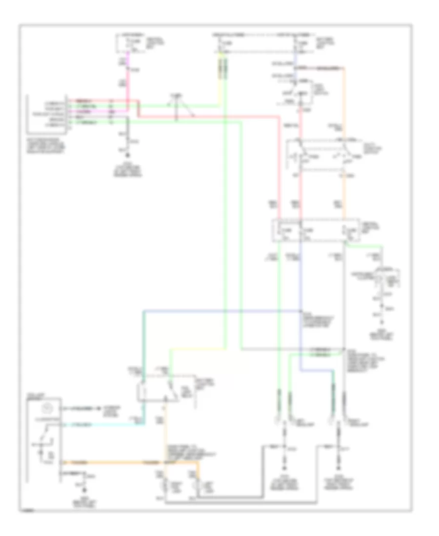
HEADLIGHTS Headlight Wiring Diagram for Ford Ranger 2000 List of elements for Headlight Wiring Diagram for Ford Ranger 2000: 47 (dash panel to headlamp junction harness, near breakout to left headlamp) s127 15a 30a Battery junction box C205 C215 C254 Central junction box Daytime running lamps (drl) module (left side of lower radiator support) Fog lamp relay Fog lamp switch Fuse Fuse 10a Fuse 15a G104 (top center of left front fender apron) G105 (top center of right front fender apron) G200 (behind left kick panel) Ground Head Hi beam in High beam ind Hot at all times Hot in run Illumination Instrument cluster Interior lights system Left fog lamp Left headlamp Lo beam in Main light switch Multi- function switch Off On ind Park Pass low Pwr (bat) Pwr (hot in run) Right fog lamp Right headlamp S117 S122 (dash panel to headlamp junction harn, near left park/turn lamp breakout) S123 S126 S140 (near breakout to windshield wiper motor) S230 S244 W/ drl
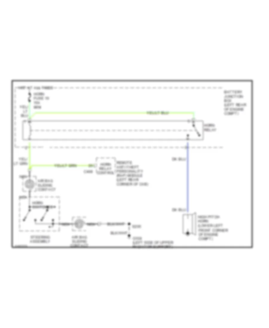
HORN Horn Wiring Diagram for Ford Ranger 2000 List of elements for Horn Wiring Diagram for Ford Ranger 2000: 15 Air bag sliding contact Battery junction box (left rear of engine compt) C409 Front corner of engine compt) G108 (left side of upper radiator support) High pitch horn (lower left Horn fuse 10 15a mini Horn relay Horn relay control Horn switches Hot at all times Nca Remote anti-theft personality (rap) module (left rear corner of cab) S205 Steering assembly
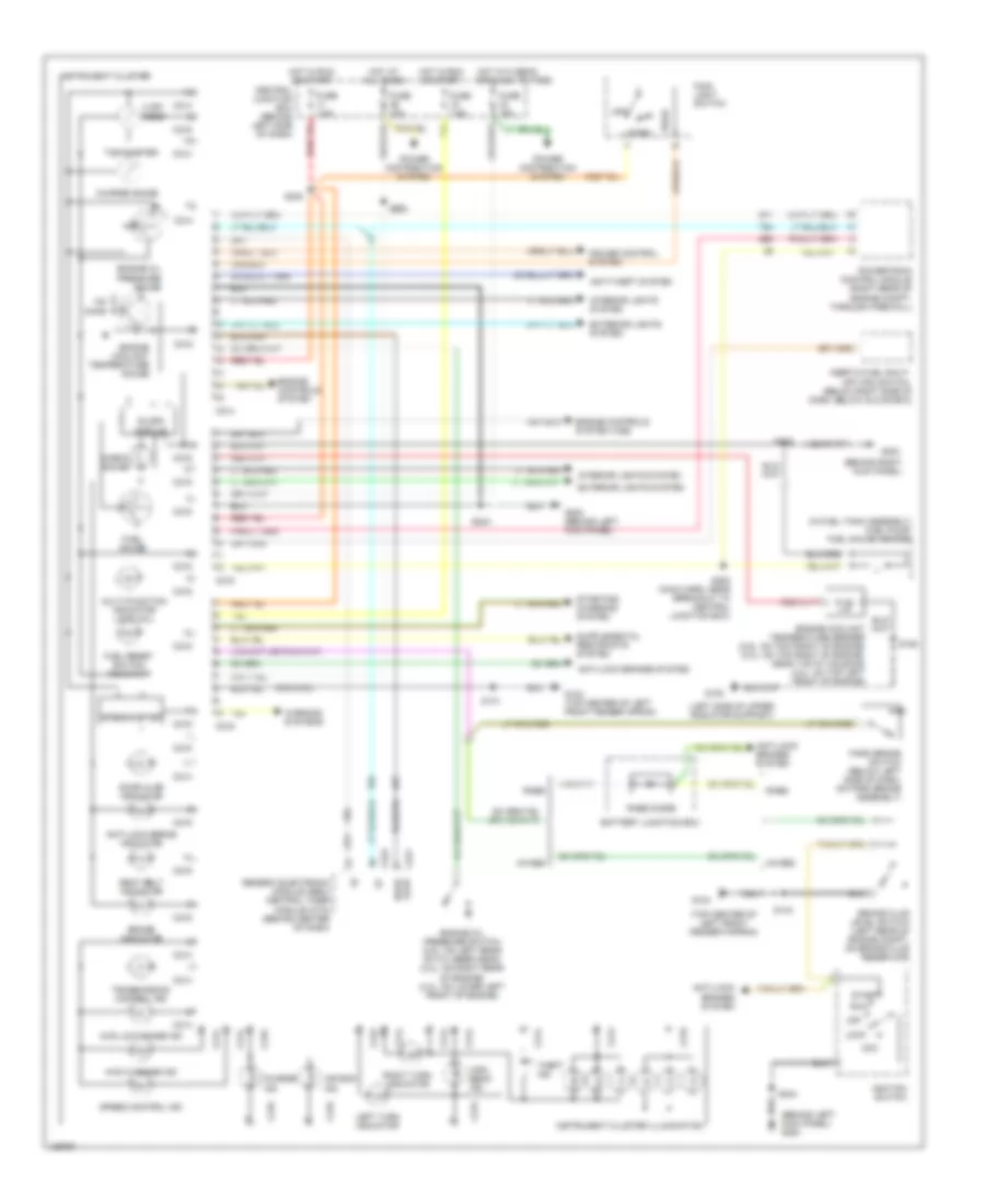
INSTRUMENT CLUSTER Instrument Cluster Wiring Diagram for Ford Ranger 2000 List of elements for Instrument Cluster Wiring Diagram for Ford Ranger 2000: 90 (3.0l/4.0l) (behind left kick panel) g200 (behind right kick panel) (in fuel tank assembly) fuel pump/ fuel gauge sender (left side of upper radiator support) (top center of left front fender fapron) 4.32k ohms 4wabs 4wd hi range ind 4wd low range ind Acc Air bag ind Anti-lock brake indicator Anti-lock brakes system Anti-theft system Battery junction box Brake fluid level switch (left rear of engine compt, on brake fluid reservoir) Brake indicator C214 C215 C216 C221 C223 Central junction box (behind left side of dash) Charge gauge Charge ind Check gauge Cruise control system Door ajar Door ajar indicator Engine controls system Engine controls system (vss) Engine coolant temperature gauge Engine coolant temperature sender (2.5l: on top front of engine) (3.0l: on top right of engine, near t-stat housing) (4.0l: on top left front of engine) Engine oil pressure gauge Engine oil pressure switch (2.5l: on left rear of cylinder head) (3.0l: on right rear of engine) (4.0l: on lower left front of engine) Exterior lights system Fuel gauge Fuel reset switch indicator Fuse 10a Fuse 15a Fuse 7.5a G104 G104 (top center of left front fender apron) G108 G200 (behind left kick panel) G203 Generic electronic module (gem)/ central timer module (ctm) (behind center of dash) Head High beam ind Hot at all times Hot in hi beam or flash to pass Hot in run or start Ignition switch Inertia fuel shut- off (ifs) switch (below right side of dash, below glove box) Instrument cluster Instrument cluster illumination Interior lights system Left turn indicator Lock Main light switch Multi-function indicator lamp (mil) Off Ohms Park Park brake switch (below left side of dash, on park brake assembly) Power distribution system Powertrain control module (right rear of engine compt, through firewall) Rabs Rabs diode Right turn indicator Run S106 S131 S143 S205 S240 S244 S253 (main harn, near breakout to central junction box) S260 Seat belt indicator Slosh module Speed control ind Speedometer Start Starting/ charging system Tachometer Theft ind Transmission control ind Warning systems
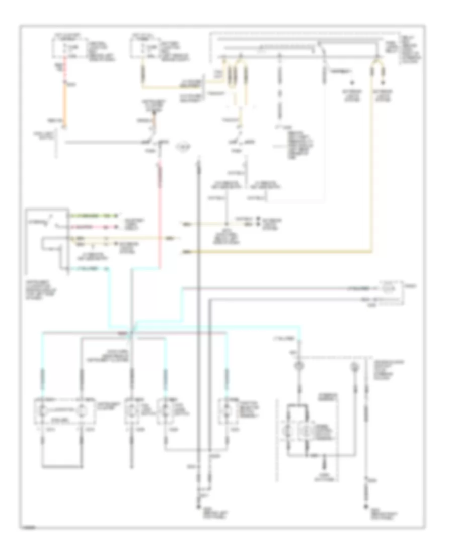
INTERIOR LIGHTS Courtesy Lamps Wiring Diagram for Ford Ranger 2000 List of elements for Courtesy Lamps Wiring Diagram for Ford Ranger 2000: 39 (left rear of vehicle) s401 (w/ power windows) (w/o power windows) 87a Battery saver relay Battery saver relay control C221 C224 C901 C902 Central juncton box (behind left side of dash) Exterior lights system Fuse 26 10a G200 (behind left kick panel) G200 (benind left kick panel) Generic electronic module (gem)/ central timer module (ctm) (behind center of dash) High mount stop lamp Hot at all times Instrument illumination dimming module (top left side of dash) Interior Interior lamp relay Interior lamp relay control Interior/ map lamp Left door ajar switch (in rear of left front door) Left door ajar switch input Left rear door ajar switch (in rear of left rear door) Outside cargo lamp Outside cargo/ high mount stop lamp Relay box (behind dash, right of steering column) Right door ajar switch (in rear of right front door) Right door ajar switch input Right rear door ajar switch (in rear of right rear door) S221 (main harness, near breakout to central junction box) S244 S260 S270 (main harn, near breakout to generic electronic module) S300 S600 s244 W/ power equipment W/o power equipment Instrument Illumination Wiring Diagram for Ford Ranger 2000 List of elements for Instrument Illumination Wiring Diagram for Ford Ranger 2000: 52 (6 bulbs) (main harn, near rear of instrument cluster) 15a 4wd mode switch 7.5a Air bag sliding contact (to of steering column) Battery junction box (left rear of engine compt) C214 C215 C225 C228 C233 C236 C409 Central junction box (behind left side of dash) Courtesy lamps circuit Exterior lights system Fog lamp switch Function selector switch assembly Fuse G200 (behind left kick panel) G203 (behind right kick panel) Head Horn switches Hot at all times Hot in start or run Illumination Instrument cluster Instrument cluster system Instrument illumination dimming module (top left side of dash) Interior Main light switch Nca Off Park Park lamps relay Radio Relay box (behind dash, right of steering column) Remote anti-theft personality (rap) module (left rear corner of cab) S205 S208 S209 S240 S244 S271 S272 (main harh, below left side of dash) Speed control switch assembly Steering assembly W/ power equipment W/ remote keyless entry W/o power equipment W/o remote keyless entry
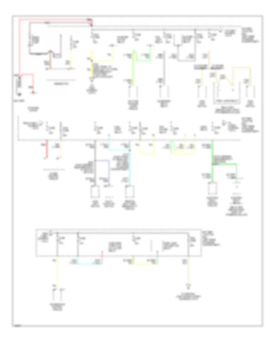
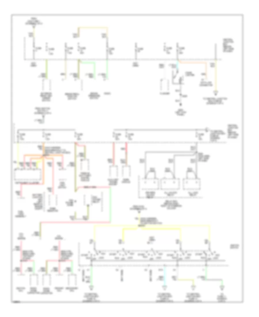
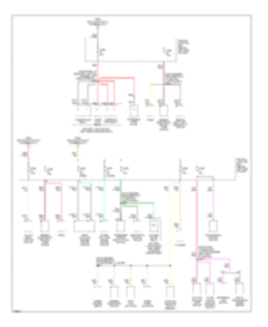
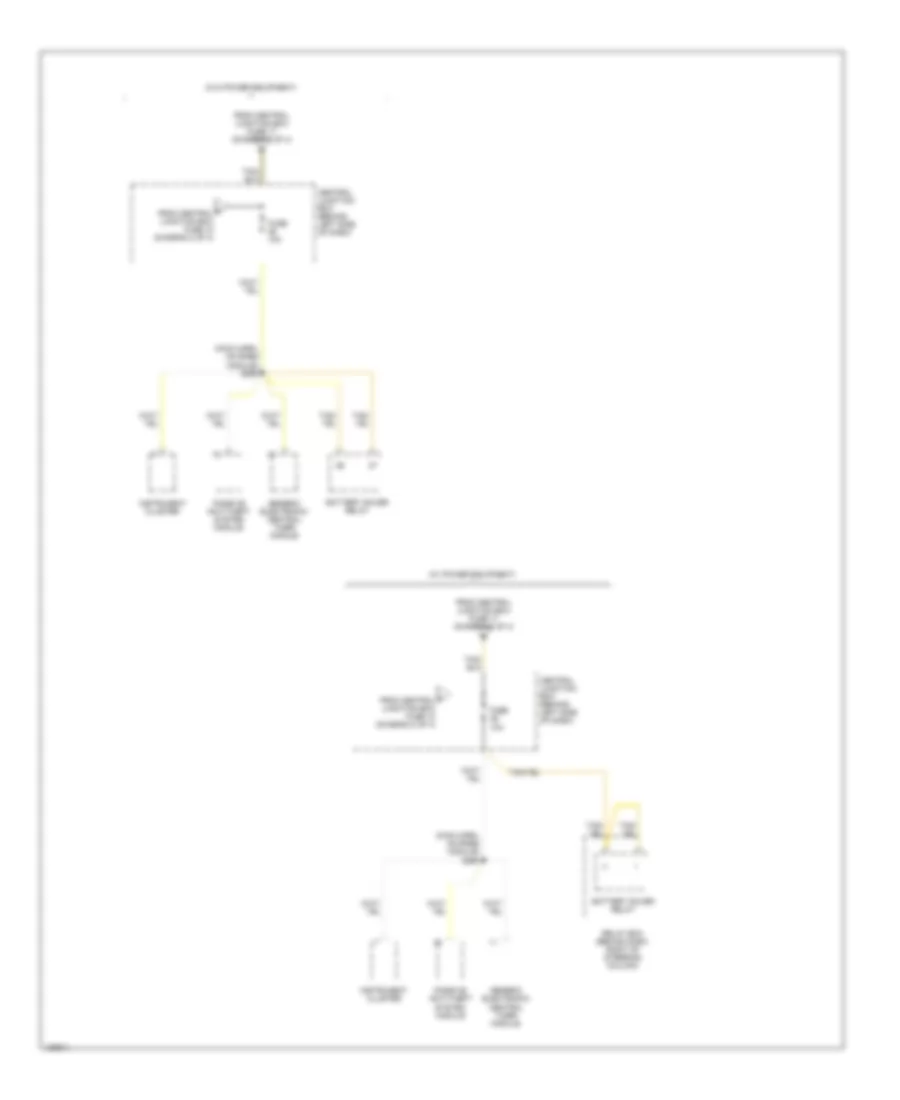
POWER DISTRIBUTION Power Distribution Wiring Diagram (1 of 4) for Ford Ranger 2000 List of elements for Power Distribution Wiring Diagram (1 of 4) for Ford Ranger 2000: 46 (main harness, near breakout for radio) s218 4wabs control module Accessory delay relay Battery Battery junction box (left rear of engine compartment) Blower motor relay C111 Daytime running lamps module Electric shift control module Electric shift relay Fog lamp relay From c fuse 3 (diagram 1 of 4) From fuse 11 b (diagram 1 of 4) Fuel pump relay Fuse 10a Fuse 15a Fuse 20a Fuse 30a Generator Horn relay Main light switch Maxi fuse 20a Maxi fuse 40a Maxi fuse 50a Mega fuse 125a Multi- function switch Nca Near breakout to battery junction block) Park lamp/ trailer tow relay Park lamps relay Pcm power relay Powertrain control module Red Relay box (behind dash, right of steering column) Remote anti-theft personality module S116 (dash panel to headlight jct harn, left rear of engine compartment) S230 (main harness, near breakout to ignition switch) Starter motor Starter motor relay To central junction box fuse 5 (diagram 2 of 4) To fuse 6 (diagram 1 of 4) To fuse 7 (diagram 1 of 4) To s232 (diagram 2 of 4) W/ power equipment W/o power equipment Wide open throttle/ a/c cutoff relay Power Distribution Wiring Diagram (2 of 4) for Ford Ranger 2000 List of elements for Power Distribution Wiring Diagram (2 of 4) for Ford Ranger 2000: 56 (eng ctrl sens harn, top right of eng) s101 (not used) 2.5l engine 3.0l/ 4.0l engine Acc All lock relay All unlock relay Auxiliary power socket Battery junction box (left rear of engine compt) Brake pedal position switch Brake pressure switch Central junction box (behind left side of dash) Cigar lighter Data link connector Driver's unlock relay Exterior rear view mirror switch Flasher From ignition switch i1 (diagram 2 of 4) From maxi fuse 1 (diagram 1 of 4) From s153 (diagram 1 of 4) Fuel tank assembly Fuse Fuse 10a Fuse 15a Fuse 20a Fuse 25a Fuse 7.5a G200 (left kick panel) Ignition coil Ignition switch Instrument cluster Lock Lock off Main light switch Off Passive anti-theft system module Pcm power diode Pcm power relay Primary coil Rabs module Rabs resistor Radio Radio noise capacitor Red Relay box (behind dash, right of steering column) Run S209 S280 (main harn, left side of dash) Secondary coil Sta Start To central junction box fuse 14 (diagram 3 of 4) To central junction box fuse 16 (diagram 3 of 4) To central junction box fuse 24 (diagram 3 of 4) To central junction box fuse 26 (diagram 4 of 4) To fuse 11 (diagram 2 of 4) Power Distribution Wiring Diagram (3 of 4) for Ford Ranger 2000 List of elements for Power Distribution Wiring Diagram (3 of 4) for Ford Ranger 2000: 44 (dash panel to headlamp junction harness, left side of firewall) s138 (dash panel to headlight junction harness, left front of vehicle) s126 (main harness, near breakout to central junction box) s238 (main harness, near breakout to central junction box) s250 (main harness, near breakout to instrument cluster) s227 4wheel anti-lock brake system module A/t Battery junction box (left rear of engine compartment) Battery junction box (left rear of engine compt) Blend door actuator Blower motor relay Central junction box (behind left side of dash) Clutch pedal position switch Daytime running lamps module Digital transmission range sensor Flasher From ignition switch a1 (diagram 2 of 4) From ignition switch a4 (diagram 2 of 4) From ignition switch sta (diagram 2 of 4) Function selector switch assembly Fuse 10a (4wabs) Fuse 15a Fuse 20a (rabs) Fuse 30a Fuse 7.5a Generic electronic module Generic electronic/ central timer module M/t Nca Passenger air bag deactivation switch Pulse vacuum hublock solenoid switch Radio Rear anti-lock brakes system module Red Remote anti-theft personality module Restraints control module Reversing lamp switch Shift lock actuator Speed control servo Transmission control switch Washer pump relay Windshield wiper motor Wiper hi/lo relay Wiper run/ park relay Power Distribution Wiring Diagram (4 of 4) for Ford Ranger 2000 List of elements for Power Distribution Wiring Diagram (4 of 4) for Ford Ranger 2000: 12 (main harn, on rabs module) s260 (w/ power equipment) (w/o power equipment) Battery saver relay Central junction box (behind left side of dash) F from central junction box fuse 18 (diagram 2 of 4) From central junction box fuse 17 (diagram 2 of 4) Fuse 10a Generic electronic/ central timer module Instrument cluster Passive anti-theft system module Relay box (behind dash, right of steering column)
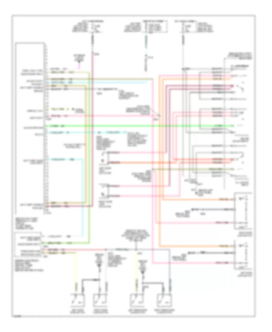
POWER DOOR LOCKS Power Door Lock Wiring Diagram for Ford Ranger 2000 List of elements for Power Door Lock Wiring Diagram for Ford Ranger 2000: 64 (behind dash, right of steering column) relay box (behind left kick panel) g200 (dlc) in (main harn, near breakout for generic electronic module) (rear of vehicle, near breakout for black 8-pin connector, under left rear of vehicle) All lock relay All unlock relay Anti-theft disable Anti-theft door ajar input Battery junction box (left rear of engine compt) C221 C222 C409 C410 Central juntion box (behind left side of dash) Data link connector (dlc) (fastened to bottom of dash, near steering column) Door disarm input Driver unlock relay Drvr door ajar Exterior lights system Fuel sys/ anti-theft mini fuse 9 20a Fuse 15a Fuse 7.5a G108 (left side of upper radiator support) G200 (behind left kick panel) Generic electronic module (gem)/ central timer module (ctm) (behind center of dash) Ground Horn rly out Horns system Hot at all times Hot in acc or run Left door ajar switch Left door lock actuator Left door lock switch Left rear door ajar switch Lock Lock in/out Park lp rly ctrl Pass door ajar Pwr (bat) Pwr (ign) Remote anti-theft personality (rap) module (in left rear corner of cab) Right door ajar switch Right door lock actuator Right door lock switch Right rear door ajar switch S116 S200 (main harn, near breakout for passenger air bag) S201 S205 S225 (main harn, near breakout for generic electronic module) S238 S244 S270 (main harn, near breakout to generic electronic module) S271 S280 S300 S401 S500 S600 Unlk Unlock drv's dr Unlock in/out W/o anti-theft system only
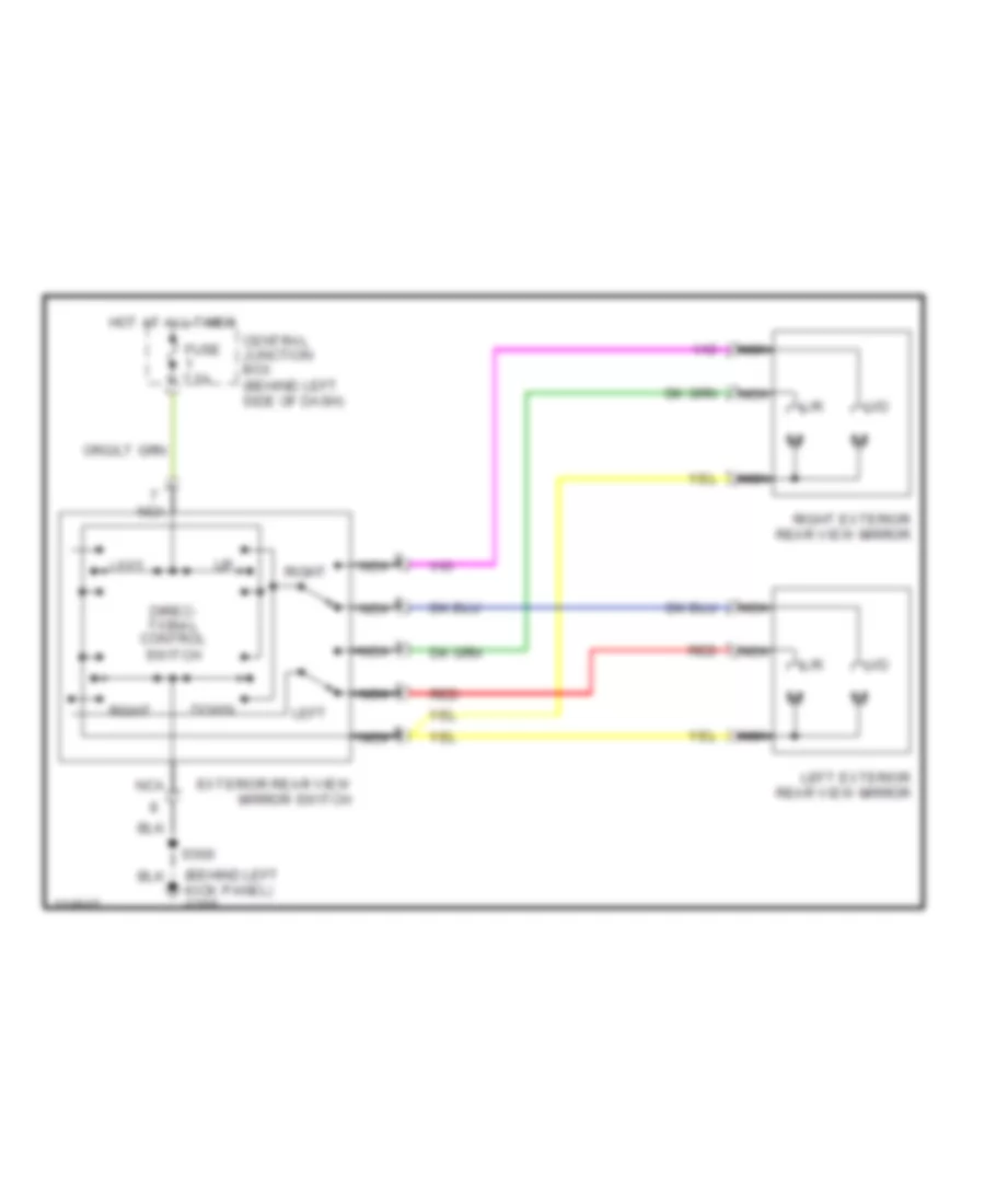
POWER MIRRORS Power Mirror Wiring Diagram for Ford Ranger 2000 List of elements for Power Mirror Wiring Diagram for Ford Ranger 2000: 16 (behind left kick panel) g200 Central junction box (behind left side of dash) Direc- tional control switch Down Exterior rear view mirror switch Fuse 7.5a Hot at all times L/r Left Left exterior rear view mirror Nca Red Right Right exterior rear view mirror S500 U/d
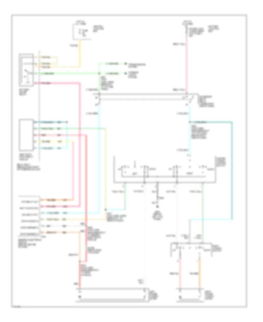
POWER WINDOWS Power Window Wiring Diagram for Ford Ranger 2000 List of elements for Power Window Wiring Diagram for Ford Ranger 2000: 35 Acc delay rly Accessory delay relay (under right side of dash) Batt savr ctrl Battery junction box Battery saver relay C224 Central junction box Down Down comnd in Down sense(hi) Down sense(lo) Fuse 10a G200 (behind left kick panel) Generic electronic module (behind center of dash) Hot at all times Inline resistance (.015 ohms) Interior lights system Left Left power window motor Master window control switch One touch down relay module Otd relay out Power lock/ window/seat maxi fuse 4 20a Red Relay box 1 (behind dash, right of steering column) Right Right power window motor Right window switch S203 (main harn, near breakout to 3 pin conn, behind right side of dash) S210 (main harn, near breakout to rear of radio) S217 (main harn, near breakout to rear of radio) S221 (main harn, near breakout to i/p fuse panel) S226 (main harn, near breakout to generic electronic module) S500 Transmissions system
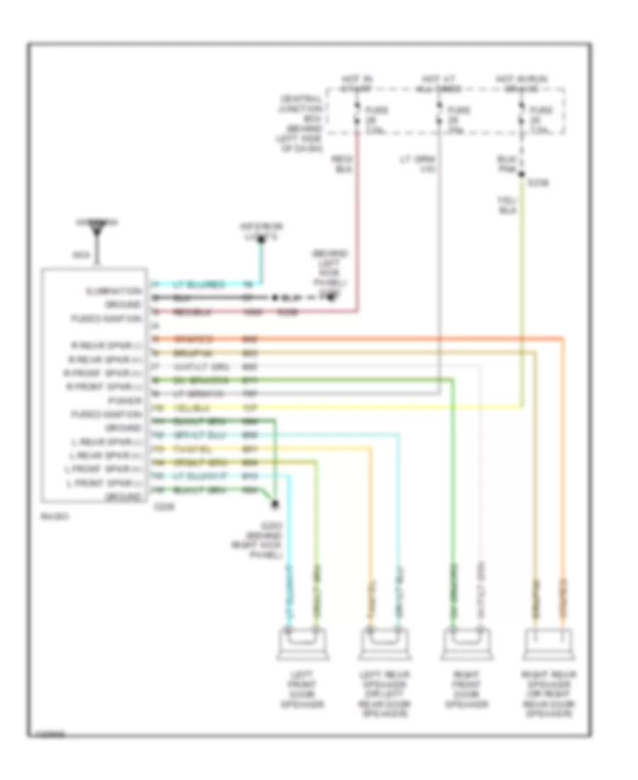
RADIO Radio Wiring Diagrams for Ford Ranger 2000 List of elements for Radio Wiring Diagrams for Ford Ranger 2000: 31 (behind left kick panel) g200 Antenna C228 Central junction box (behind left side of dash) Fuse 15a Fuse 7.5a Fused ignition G203 (behind right kick panel) Ground Hot at all times Hot in run or acc Hot in start Ilumination Interior lights L front spkr (+) L front spkr (-) L rear spkr (+) L rear spkr (-) Left front door speaker Left rear speaker (or left rear door speaker) Nca Power R front spkr (+) R front spkr (-) R rear spkr (+) R rear spkr (-) Radio Right front door speaker Right rear speaker (or right rear door speaker) S209 S238
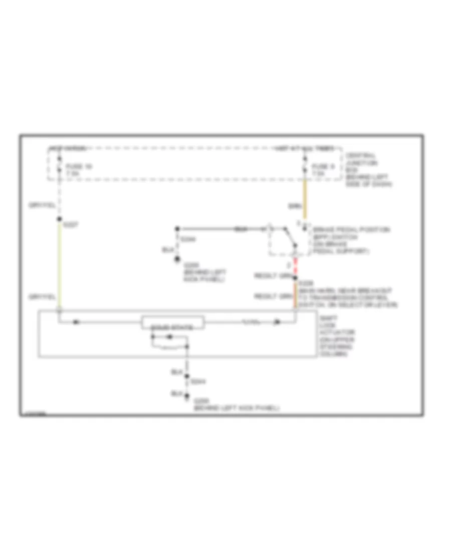
SHIFT INTERLOCKS Shift Interlock Wiring Diagram for Ford Ranger 2000 List of elements for Shift Interlock Wiring Diagram for Ford Ranger 2000: 12 Brake pedal position (bpp) switch (on brake pedal support) Central junction box (behind left side of dash) Fuse 10 7.5a Fuse 9 7.5a G200 (behind left kick panel) Hot at all times Hot in run S227 S228 (main harn, near breakout to transmission control switch, on selector lever) S244 Shift lock actuator (on upper steering column) Solid state
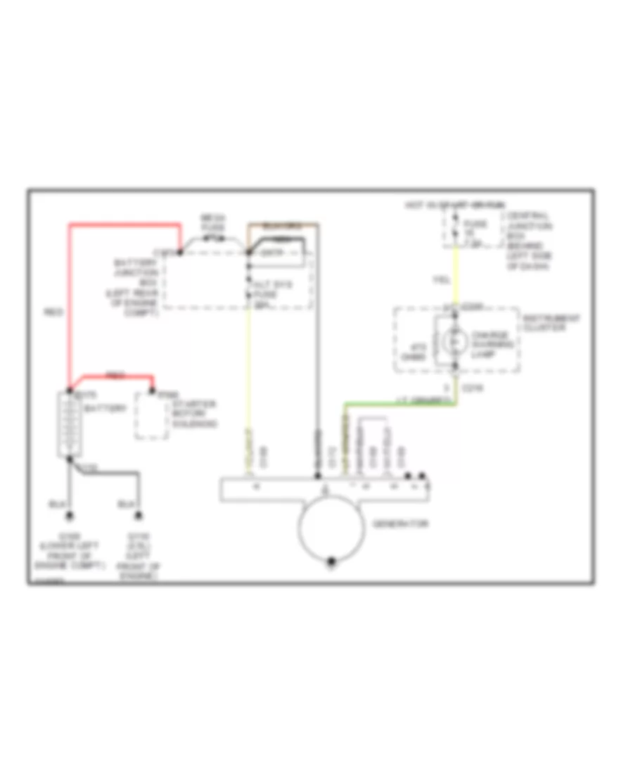
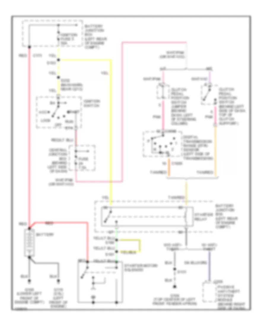
STARTING/CHARGING Charging Wiring Diagram for Ford Ranger 2000 List of elements for Charging Wiring Diagram for Ford Ranger 2000: 25 Alt sys fuse 30a Battery Battery junction box (left rear of engine compt) C110 C168 C169 C172 C173 C175 C177 C186 C216 Central junction box (behind left side of dash) Charge warning lamp Fuse 7.5a G100 (lower left front of engine compt) G110 (2.5l) (left front of engine) Generator Hot in start or run Instrument cluster Mega fuse 175a Nca Ohms Red Starter motor/ solenoid Starting Wiring Diagram for Ford Ranger 2000 List of elements for Starting Wiring Diagram for Ford Ranger 2000: 35 A/t Acc Battery Battery junction box (left rear of engine compt) C1005 C173 C255 Central junction box (behind left side of dash) Clutch pedal position switch (behind left side of dash, top of clutch support) Clutch pedal position switch jumper (behind dash, left of steering column) Digital transmission range (dtr) sensor (left side of transmission) Fuse 7.5a G100 (lower left front of engine compt) G104 (top center of left front fender apron) G110 (2.5l) (left front of engine) Ignition fuse 5 50a Ignition switch Lock M/t Off Passive anti-theft system module (behind right side of dash) Pnk Red Run S131 S153 S191 S232 (main harn, near c213) Sta Start Starter motor/ solenoid Starter relay Tan/red W/ anti- theft W/o anti- theft
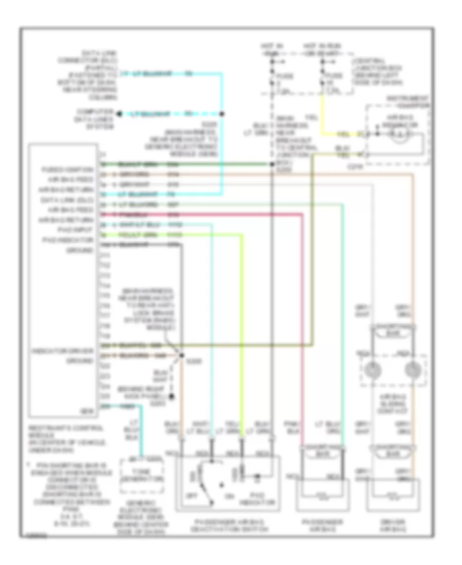
SUPPLEMENTAL RESTRAINTS Supplemental Restraint Wiring Diagram for Ford Ranger 2000 List of elements for Supplemental Restraint Wiring Diagram for Ford Ranger 2000: 36 (behind right kick panel) g203 (main harness, near breakout to central junction box) s250 (main harness, near breakout to rear anti- lock brake system (rabs) module) Air bag feed Air bag indicator Air bag return Air bag sliding contact C216 C221 Central junction box (behind left side of dash) Computer data lines system Data link (dlc) Data link connector (dlc) (partial) (fastened to bottom of dash, near steering column) Driver air bag Fuse 7.5a Fused ignition Gem Generic electronic module (gem) (behind center side of dash) Ground Hot in run Hot in run or start Indicator driver Instrument cluster Nca Off Ohms Pad indicator Pad input Passenger air bag Passenger air bag deactivation switch Pin shorting bar is engaged when module connector is disconnected (shorting bar is connected between pins: 3-4, 6-7, 8-10, 20-21) Restraints control module (in center of vehicle, under dash) S205 S225 (main harness, near breakout to generic electronic module (gem)) Shorting bar Tone generator
TRANSMISSION
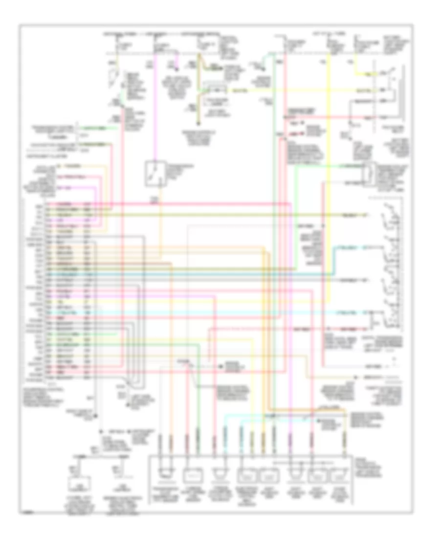
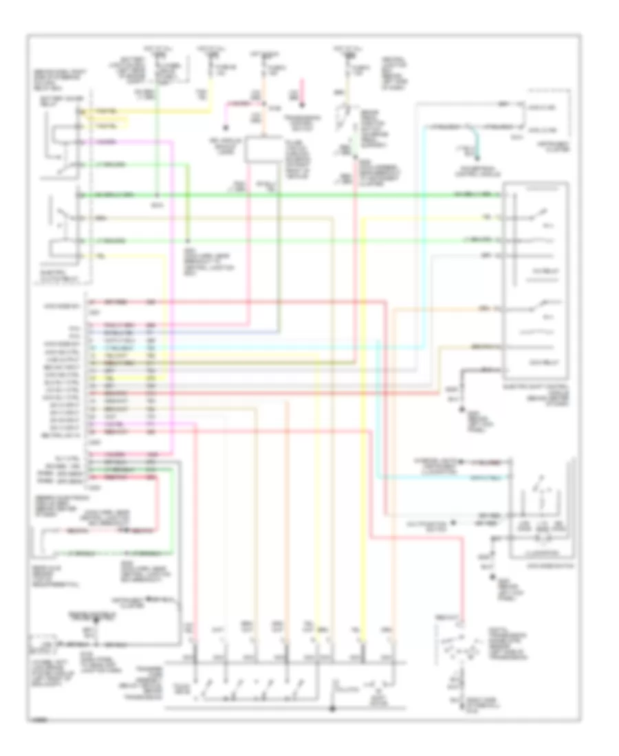
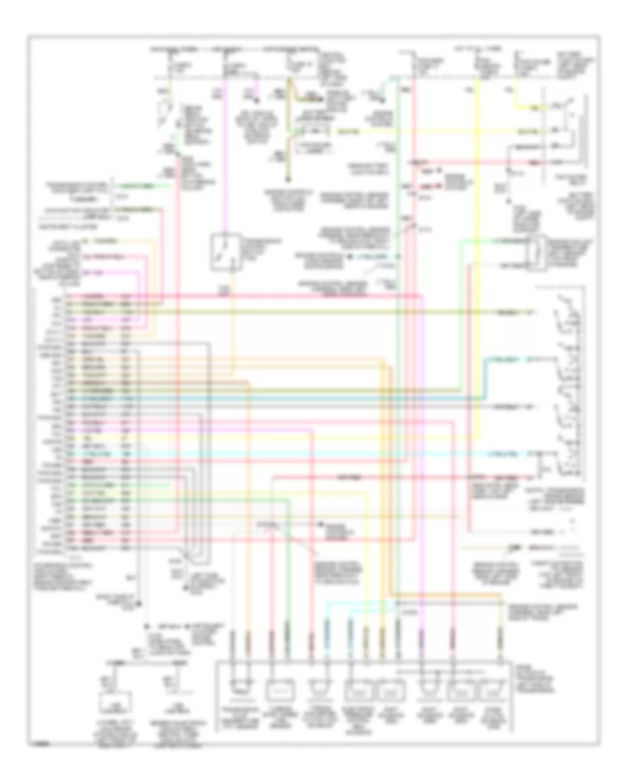
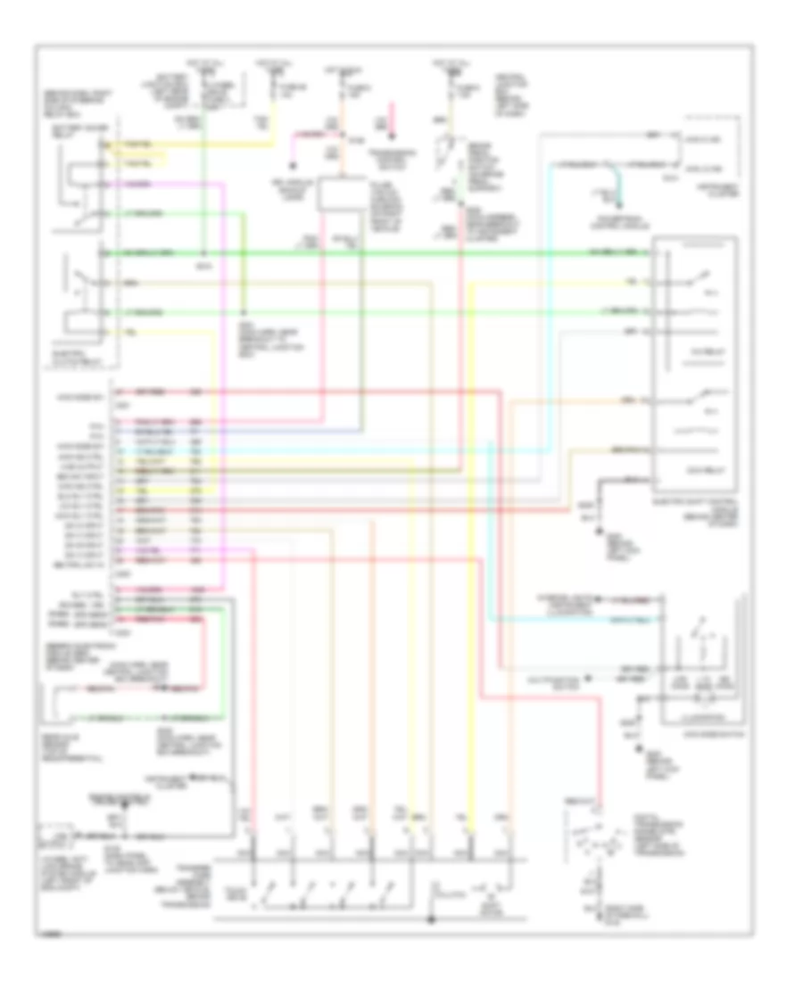
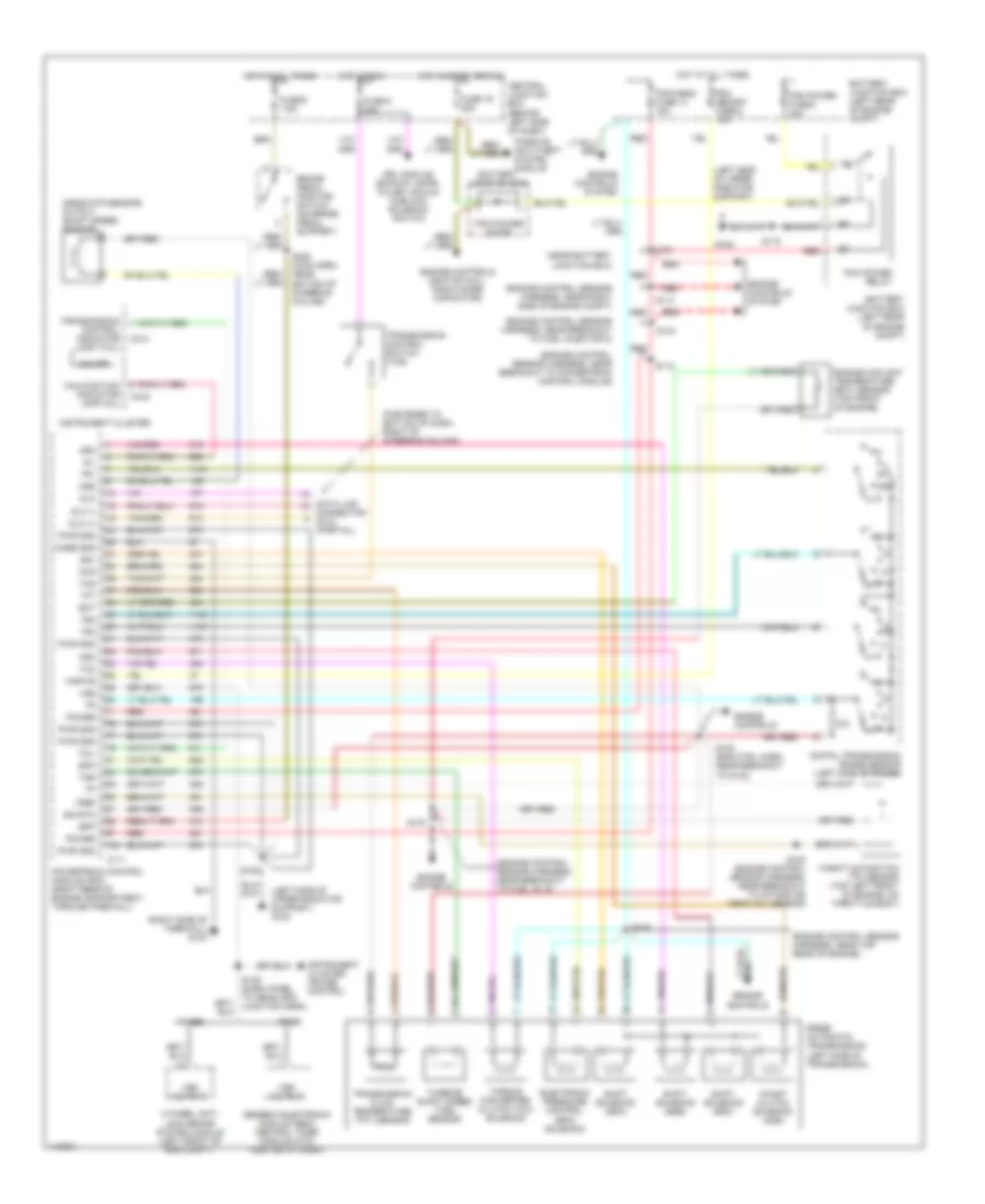
2.5L 2.5L, A/T Wiring Diagram, 4R44E for Ford Ranger 2000 List of elements for 2.5L, A/T Wiring Diagram, 4R44E for Ford Ranger 2000: 91 (engine control sensor harness, near breakout to ground g123) (engine control sensor harness, near right rear of engine) (left side of radiator support) g108 (near battery junction box) s121 (right side of firewall) g123 4-wheel anti- lock brake system module (left front of eng compt) 4r44e automatic transmission (left side of transmission) 4wabs Battery junction box Battery junction box (left rear of engine compt) Bpp Brake pedal position switch (on brake pedal support) C111 C214 C216 Ccs Central junction box (behind left side of dash) Coast clutch solenoid (css) Cse gnd Data link connector (dlc) (partial) (fastened to bottom of dash, near steering column) Digital transmission range sensor (left side of trans) Dlc Dlc (+) Dlc (-) Drl module, back-up lamps, pulse vacuum hublock solenoid switch Ect Electronic pressure control (epc) solenoid Engine controls (ignition coil, radio noise capacitor) Engine controls system Engine coolant temperature (ect) sensor (top right front of eng, in water outlet tube) Epc Fuse 19 25a Fuse 6 15a Fuse 9 7.5a G108 (left side of upper radiator support) Generic electronic module (gem)/ central timer module (ctm) (center of dash) Hot at all times Hot in run Hot in start or run Instrument cluster Instrument cluster, cruise control Kapwr Malfunction indicator lamp (mil) Mil O/d off Passive anti-theft system module Pcm memory fuse 6 10a Pcm power diode Pcm power fuse 8 30a Pcm power relay Pcm/hego fuse 13 15a Power Powertrain control module (pcm) (right rear of engine compartment, through firewall) Pwr gnd R p Rabs Red S100 (engine control sensor harness, near breakout to tp sensor) S102 (eng cntrl sens harn, near breakout to intake air temp (iat) sensor) S103 S104 (engine control sensor harness, near breakout to ground g123, right side of firewall) S105 (eng cntrl sens harn, near left side of trans) S106 S109 S118 S139 (dash panel to headlamp junction harn) S228 (main harn, near bottom of steering column) Shift solenoid (ssa) Shift solenoid (ssb) Shift solenoid (ssc) Sig rtn Ss1 Ss2 Ss3 Tcc Tcil Tcs Tft Throttle position (tp) sensor (top right side of engine, on throttle body) Torque converter clutch (tcc) solenoid Tr1 Tr2 Tr4 Transmission control indicator lamp (tcil) Transmission control switch (tcs) Transmission fluid temperature (tft) sensor Tss Turbine shaft speed (tss) sensor Vref Vss Vss output 4WD Wiring Diagram for Ford Ranger 2000 List of elements for 4WD Wiring Diagram for Ford Ranger 2000: 74 (behind dash, right side of steering column) relay box (main harn, near central junction box breakout) s235 red/pnk (rabs) (rwabs) 1.1k ohms 3.9k ohms 4 wheel drive fuse 3 20a 4-wheel anti- lock brake system module (left front of eng compt) 4wd hi ind 4wd ind ctrl 4wd lo ind 4wd mode sw 4wd mode switch 4wd output Battery junction box (left rear of engine compt) Battery saver relay Boo sw input Brake pedal position switch (on brake pedal support) C214 C221 C223 C224 Ccw relay Ccw rly ctrl Central junction box (behind left side of dash) Clutch Cw relay Cw rly ctrl Digital transmission range (dtr) sensor (left side of transmission) Drl module, backup lamps Elc rly ctrl Electric clutch relay Electric shift control module (behind center of dash) Engine controls, cruise control Fuse 26 10a Fuse 6 15a Fuse 9 7.5a G200 (behind left kick panel) Generic electronic module (gem) (behind center of dash) Hot at all times Hot in run Illumination Instrument cluster Interior lights (instrument illumination) Multifunction switch Nca Neutral sw in Of firewall) g123 Ohms Powertrain control module Pulse vacuum hublock solenoid (on right front of vehicle) Pvh Rear axle sensor (top of readifferential) Red/pnk Rly ctrl S107 S126 S139 (dash panel to headlamp junction harn) S209 S218 S221 (main harn, near breakout to central junction box) S228 (main harness, near breakout to instrument cluster) S235 (main harn, near central junction box breakout) Shift motor Spd sens Sw a input Sw b input Sw c input Sw d input Touch drive Transfer case assembly (below vehicle, behind transmission) Transmission control switch Vss Vss output
3.0L 3.0L, A/T Wiring Diagram, 4R44E for Ford Ranger 2000 List of elements for 3.0L, A/T Wiring Diagram, 4R44E for Ford Ranger 2000: 99 (eng cntrl sens harn, top left rear of eng) (engine control sensor harness, near breakout to ground g123) (engine control sensor harness, near breakout to ground g123, right side of firewall) (engine control sensor harness, near left rear of engine) (engine control sensor harness, near left side of engine) (engine control sensor harness, near left side of trans) (engine control sensor harness, near top left rear of engine) (left side of radiator support) g108 (near battery junction box) (right side of firewall) g123 4-wheel anti- lock brake system module (left front of eng compt) 4r44e automatic transmission (left side of transmission) 4wabs Battery junction box Battery junction box (left rear of engine compt) Bpp Brake pedal position switch (on brake pedal support) C111 C214 C216 Ccs Central junction box (behind left side of dash) Coast clutch solenoid (css) Cse gnd Data link connector (dlc) (partial) (fastened to bottom of dash, near steering column) Digital transmission range sensor (left side of trans) Dlc Dlc (+) Dlc (-) Drl module, back-up lamps, pulse vacuum hublock solenoid switch Ect Electronic pressure control (epc) solenoid Engine controls (ho2s sensor, evr solenoid) Engine controls (ignition coil, radio noise capacitor) Engine controls system Engine coolant temperature (ect) sensor (top front of engine) Epc Fuse 19 25a Fuse 6 15a Fuse 9 7.5a G108 (left side of upper radiator support) Generic electronic module (gem)/ central timer module (ctm) (center of dash) Hot at all times Hot in run Hot in start or run Instrument cluster Instrument cluster, cruise control Kapwr Malfunction indicator lamp (mil) Mil O/d off Passive anti-theft system module Pcm memory fuse 6 10a Pcm power diode Pcm power fuse 8 30a Pcm power relay Pcm/hego fuse 13 15a Power Powertrain control module (pcm) (right rear of engine compartment, through firewall) Pwr gnd R p Rabs Red S100 S1002 S102 S103 S104 S106 S109 S112 S118 S121 S139 (dash panel to headlamp junction harn) S228 (main harn, near bottom of steering column) Shift solenoid (ssa) Shift solenoid (ssb) Shift solenoid (ssc) Sig rtn Ss1 Ss2 Ss3 Tcc Tcil Tcs Tft Throttle position (tp) sensor (top left front of engine, on throttle body) Torque converter clutch (tcc) solenoid Tr1 Tr2 Tr4 Transmission control indicator lamp (tcil) Transmission control switch (tcs) Transmission fluid temperature (tft) sensor Tss Turbine shaft speed (tss) sensor Vref Vss Vss output 4WD Wiring Diagram for Ford Ranger 2000 List of elements for 4WD Wiring Diagram for Ford Ranger 2000: 74 (behind dash, right side of steering column) relay box (main harn, near central junction box breakout) s235 red/pnk (rabs) (rwabs) 1.1k ohms 3.9k ohms 4 wheel drive fuse 3 20a 4-wheel anti- lock brake system module (left front of eng compt) 4wd hi ind 4wd ind ctrl 4wd lo ind 4wd mode sw 4wd mode switch 4wd output Battery junction box (left rear of engine compt) Battery saver relay Boo sw input Brake pedal position switch (on brake pedal support) C214 C221 C223 C224 Ccw relay Ccw rly ctrl Central junction box (behind left side of dash) Clutch Cw relay Cw rly ctrl Digital transmission range (dtr) sensor (left side of transmission) Drl module, backup lamps Elc rly ctrl Electric clutch relay Electric shift control module (behind center of dash) Engine controls, cruise control Fuse 26 10a Fuse 6 15a Fuse 9 7.5a G200 (behind left kick panel) Generic electronic module (gem) (behind center of dash) Hot at all times Hot in run Illumination Instrument cluster Interior lights (instrument illumination) Multifunction switch Nca Neutral sw in Of firewall) g123 Ohms Powertrain control module Pulse vacuum hublock solenoid (on right front of vehicle) Pvh Rear axle sensor (top of readifferential) Red/pnk Rly ctrl S107 S126 S139 (dash panel to headlamp junction harn) S209 S218 S221 (main harn, near breakout to central junction box) S228 (main harness, near breakout to instrument cluster) S235 (main harn, near central junction box breakout) Shift motor Spd sens Sw a input Sw b input Sw c input Sw d input Touch drive Transfer case assembly (below vehicle, behind transmission) Transmission control switch Vss Vss output
4.0L 4.0L, A/T Wiring Diagram, 5R55E for Ford Ranger 2000 List of elements for 4.0L, A/T Wiring Diagram, 5R55E for Ford Ranger 2000: 102 (engine control sensor harness, near breakout to fuel inj 6) (engine control sensor harness, near breakout to fuel injector 5) (engine control sensor harness, near breakout to powertrain control module) (engine control sensor harness, near right side of engine compt) (engine control sensor harness, near top rear of engine) (fastened to bottom of dash, right of steering column) (left side of upper radiator support) (left side of upper radiator support) g108 (near battery junction box) (near dtr sensor) output shaft speed sensor (right side of firewall) g123 4-wheel anti- lock brake system module (left front of eng compt) 4wabs 5r55e automatic transmission (left side of transmission) Battery junction box Battery junction box (left rear of engine compt) Bpp Brake pedal position switch (on brake pedal support) C111 C214 C216 Case gnd Ccs Central junction box (behind left side of dash) Coast clutch solenoid (css) Connector (dlc) (partial) Data link Digital transmission range sensor (left side of trans) Dlc Dlc (+) Dlc (-) Drl module, backup lamps, pulse vacuum hublock solenoid switch Ect Electronic pressure control (epc) solenoid Engine controls Engine controls (ignition coil, radio noise capacitor) Engine controls system Engine coolant temperature (ect) sensor (top front of engine) Epc Fuse 19 25a Fuse 6 15a Fuse 9 7.5a G108 Generic electronic module (gem)/ central timer module (ctm) (center of dash) Hot at all times Hot in run Hot in start or run Instrument cluster Instrument cluster, cruise control Kapwr Malfunction indicator lamp (mil) Mil O/d off Oss Passive anti-theft system module Pcm memory fuse 6 10a Pcm power diode Pcm power fuse 8 30a Pcm power relay Pcm/hego fuse 13 15a Power Powertrain control module (pcm) (right rear of engine compartment, through firewall) Pwr gnd R p Rabs Red S100 (engine control sensor harness, near breakout to intake air temp (iat) sensor) S102 (eng ctrl harn, near breakout to g123) S103 S104 S106 S109 S112 S113 S118 S121 S139 (dash panel to headlamp junction harn) S228 (main harn, near bottom of steering column) Shift solenoid (ssa) Shift solenoid (ssb) Shift solenoid (ssc) Sig rtn Ss1 Ss2 Ss3 Tcc Tcil Tcs Tft Throttle position (tp) sensor (top left front of engine, on throttle body) Torque converter clutch (tcc) solenoid Tr1 Tr2 Tr4 Transmission control indicator lamp (tcil) Transmission control switch (tcs) Transmission fluid temperature (tft) sensor Tss Turbine shaft speed (tss) sensor Vref Vss Vss output 4WD Wiring Diagram for Ford Ranger 2000 List of elements for 4WD Wiring Diagram for Ford Ranger 2000: 74 (behind dash, right side of steering column) relay box (main harn, near central junction box breakout) s235 red/pnk (rabs) (rwabs) 1.1k ohms 3.9k ohms 4 wheel drive fuse 3 20a 4-wheel anti- lock brake system module (left front of eng compt) 4wd hi ind 4wd ind ctrl 4wd lo ind 4wd mode sw 4wd mode switch 4wd output Battery junction box (left rear of engine compt) Battery saver relay Boo sw input Brake pedal position switch (on brake pedal support) C214 C221 C223 C224 Ccw relay Ccw rly ctrl Central junction box (behind left side of dash) Clutch Cw relay Cw rly ctrl Digital transmission range (dtr) sensor (left side of transmission) Drl module, backup lamps Elc rly ctrl Electric clutch relay Electric shift control module (behind center of dash) Engine controls, cruise control Fuse 26 10a Fuse 6 15a Fuse 9 7.5a G200 (behind left kick panel) Generic electronic module (gem) (behind center of dash) Hot at all times Hot in run Illumination Instrument cluster Interior lights (instrument illumination) Multifunction switch Nca Neutral sw in Of firewall) g123 Ohms Powertrain control module Pulse vacuum hublock solenoid (on right front of vehicle) Pvh Rear axle sensor (top of readifferential) Red/pnk Rly ctrl S107 S126 S139 (dash panel to headlamp junction harn) S209 S218 S221 (main harn, near breakout to central junction box) S228 (main harness, near breakout to instrument cluster) S235 (main harn, near central junction box breakout) Shift motor Spd sens Sw a input Sw b input Sw c input Sw d input Touch drive Transfer case assembly (below vehicle, behind transmission) Transmission control switch Vss Vss output
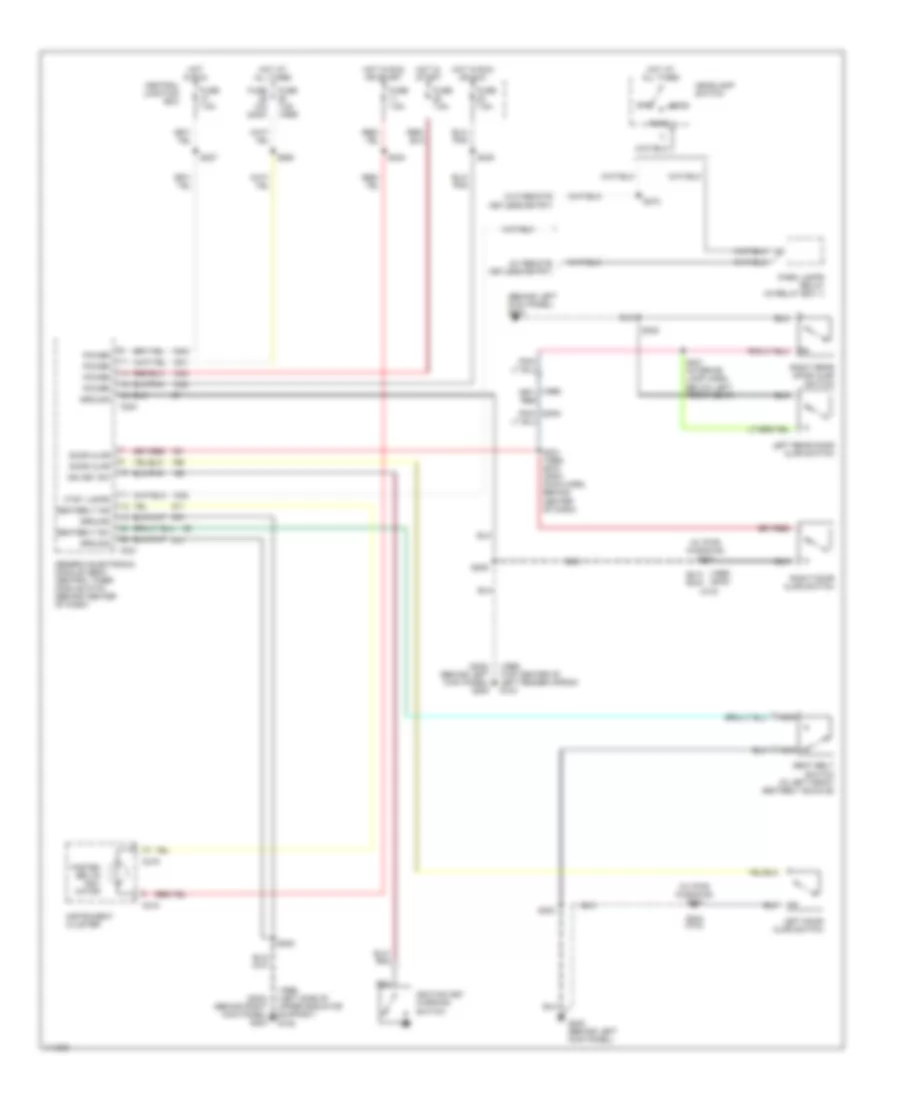
WARNING SYSTEMS Warning System Wiring Diagrams for Ford Ranger 2000 List of elements for Warning System Wiring Diagrams for Ford Ranger 2000: 60 (1999) (2000) (1999) (left side of upper radiator support) g108 (1999) (top center of left fender apron) g104 (2000) (behind left kick panel) g200 (2000) (behind right kick panel) g203 (behind left kick panel) g200 (w/ pwr windows) s500 (w/ pwr windows) s600 (w/ remote keyless entry) (w/o remote keyless entry) (w/o) C215 C216 C221 C224 Central junction box Ctsy lamps Door ajar Fasten belts indi- cator Fuse 10a (2000) Fuse 7.5a Fuse 7.5a (1999) G200 (behind left kick panel) Generic electronic module (gem)/ central timer module (ctm) (behind center of dash) Ground Head Headlamp switch Hot at all times Hot in run Hot in run or acc Hot in run or start Hot in start Ign key sw Ignition key warning switch Instrument cluster Left door ajar switch Left rear door ajar switch Nca Off Park Park lamps relay (in relay box 1) Pnk/ (2000) Power Right door ajar switch Right rear door ajar switch S205 S209 S214 s244 S227 S231 (1999) s270 (2000) (main harn, behind center of dash) S238 S240 S244 (w/o) S260 S272 S300 S401 (interior lamp harn, below left front seat) Seat belt switch (in left front seatbelt buckle) Seatbelt ind Seatbelt sw
WIPER/WASHER Wiper/Washer Wiring Diagram for Ford Ranger 2000 List of elements for Wiper/Washer Wiring Diagram for Ford Ranger 2000: 45 1370k 1910k 249k 2670k 401k 402k 634k 955k 956k Battery junction box (left rear of engine compartment) C221 C254 Central junction box (behind left side of dash) Circuit breaker Fuse 30a G104 (rear of left front fender) G105 (top center of right front fender apron) Generic electronic module/ central timer module (behind center of dash) Hot in acc or run Int Interval delay wash input Mode select switch input Multi- function switch Off Park Park sense Red Return Run Run/park relay control S117 S133 (dash to headlamp harness, near breakout to windshield wiper motor) S138 S143 S215 (main harness, near breakout to gem) Tan/red Washer pump relay Washer pump relay control Washer switch Windshield washer pump (in washer reservoir) Windshield wiper motor Wiper hi-lo relay Wiper high/low relay control Wiper run/ park relay Wiper switch