Diagram sections — 29 (56 total)
AIR CONDITIONING ANTI-LOCK BRAKES ANTI-THEFT BODY COMPUTER COMPUTER DATA LINES COOLING FAN CRUISE CONTROL DEFOGGERS ENGINE PERFORMANCE EXTERIOR LIGHTS GROUND DISTRIBUTION HEADLIGHTS HORN INSTRUMENT CLUSTER INTERIOR LIGHTS NAVIGATION POWER DISTRIBUTION POWER DOOR LOCKS POWER MIRRORS POWER SEATS POWER WINDOWS RADIO SHIFT INTERLOCKS STARTING/CHARGING SUPPLEMENTAL RESTRAINTS TRANSMISSION TRUNK, TAILGATE, FUEL DOOR WARNING SYSTEMS WIPER/WASHER
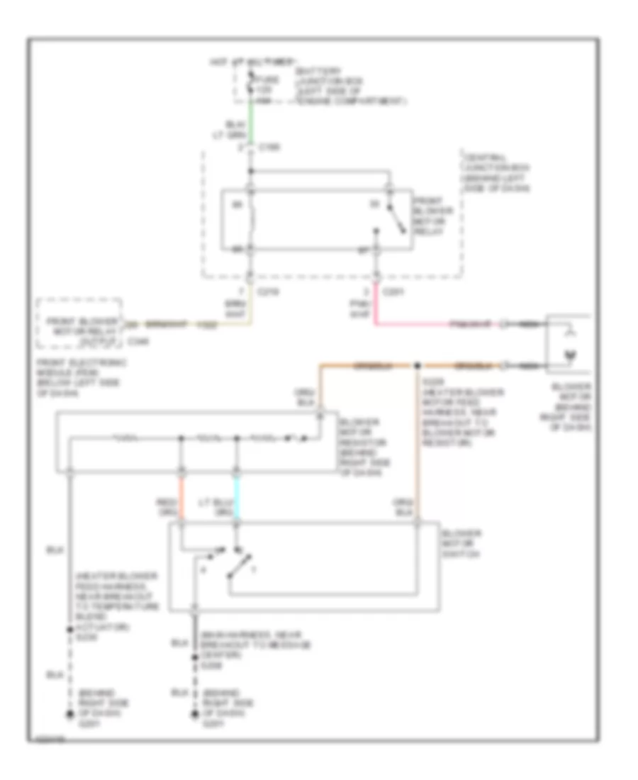
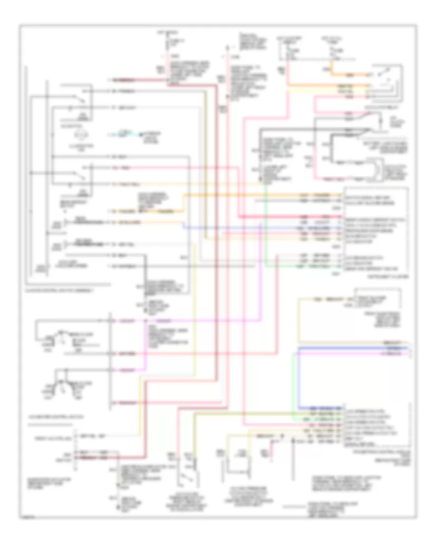
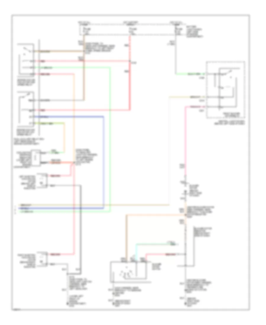
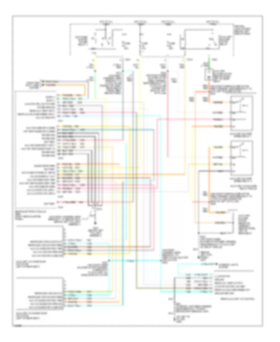
AIR CONDITIONING Heater Wiring Diagram for Ford Windstar 2000 List of elements for Heater Wiring Diagram for Ford Windstar 2000: 20 (behind right side of dash) g201 (heater blower feed harness, near breakout to temperature blend actuator) s230 (main harness, near breakout to message center) s208 Battery junction box (left side of engine compartment) Blower motor (behind right side of dash) Blower motor resistor (behind right side of dash) Blower motor switch C195 C201 C219 C346 Central junction box (behind left side of dash) Front blower Front blower motor relay Front electronic module (fem) (below left side of dash) Fuse 40a Hot at all times Motor relay output Nca S229 (heater blower motor feed harness, near breakout to blower motor resistor) Manual A/C Wiring Diagram (1 of 2) for Ford Windstar 2000 List of elements for Manual A/C Wiring Diagram (1 of 2) for Ford Windstar 2000: 77 (behind right side of dash) g201 (dash panel to headlamp junction harness, near breakout to left headlamp) s115 (dash panel to headlamp junction harness, near breakout to (42 pin) in-line connector, left rear of engine compartment) (dash panel to headlamp junction harness, near breakout to ground g100, lower left front of engine compartment) s112 (dash panel to headlamp junction harness, near breakout to left headlamp) (heater blower motor feed harness, near breakout to temperature blend actuator) (lower left front of engine compartment) g100 (main harness, near breakout to (16 pin) in-line connector, under left side of dash) s219 (main harness, near breakout to message center) s212 A/c clutch cycling sw A/c clutch diode A/c clutch field coil (left front of engine) A/c clutch relay A/c cycling pressure switch (right rear of engine compartment on accumulator) A/c demand switch A/c high press cutout sw A/c high pressure cutout/fan switch (3.0l engine only) (center front of engine compartment) A/c indicator A/c switch A/c-heater control switch Auxiliary blower sense Auxiliary blower speed Battery junction box (left side of engine compartment) Blend door actuator (behind right side of dash) Blower switch C195 C202 C239 C240 C241 C346 Central junction box (behind left side of dash) Climate control switch assembly Def Driver's temperature Floor Front a/c ctrl sig Front blower motor relay output Front electronic module (fem) (below left side of dash) Fuse 10 10a Fuse 10a Fuse 15a Gnd High speed fan ctrl Hot at all times Hot in run Hot in start or run Ignition Illumination (x5) Instrument cluster Interior lights system Low speed fan ctrl Main lt & a/c mode sw rtn Max Message center) s208 Mix Nca Norm Off Ohms Panel/floor Pnk Powertrain control module (pcm) (behind right side of dash) Rear blend door sense Rear defrost switch Rear temperature Rear wdo defrost (on) ind Rear window defrost switch Ref volt S117 S131 S221 (main harness, near breakout to instrument cluster connector c239) S230 Signal return Switch signal return Vent Wot a/c wac cutout rly Manual A/C Wiring Diagram (2 of 2) for Ford Windstar 2000 List of elements for Manual A/C Wiring Diagram (2 of 2) for Ford Windstar 2000: 30 (behind right side of dash) g201 (dash panel to headlamp harness, near breakout to left front wheel speed sensor) s123 (dash panel to headlamp junction harness, near breakout to left engine cooling fan) s113 (heater blower motor feed harness, near breakout to blower motor resistor) s229 (lower left front of engine compartment) g100 Battery junction box (left side of engine compartment) Blower motor (behind right side of dash) Blower motor resistor (behind right side of dash) Blower motor switch C195 C201 C219 Central junction box (behind left side of dash) Cooling fan dropping resistor (lower left front of engine compartment) Dual auxiliary relay box (left rear side of engine compartment) Engine cooling fan motor high speed relay Engine cooling fan motor low speed relay Front blower motor relay Fuse 15a Fuse 40a Fuse 50a Hot at all times Hot in start or run Left electric cooling fan motor (behind left side of radiator) Nca Near breakout to temperature blend actuator) s230 Red Right electric cooling fan motor (behind right side of radiator) S116 (dash panel to headlamp junction harness, near breakout to left headlamp) S125 Manual A/C Wiring Diagram, Rear A/C for Ford Windstar 2000 List of elements for Manual A/C Wiring Diagram, Rear A/C for Ford Windstar 2000: 73 (air conditioner blower motor feed harness, near breakout to (12 pin) in-line connector, back of left "b" pillar) s346 (behind left kick panel) g200 (main body harness, near breakout to ground g404, behind left taillight assembly) (main body harness, near breakout to inertia fuel shutoff (ifs) switch) s308 (on left "b" pillar) g308 Air temp blend dr closed Aux a/c blend dr close sig Aux a/c blend dr open sig Aux a/c blend dr posit ref Aux a/c gnd rtn Aux a/c mod dr close sig Aux a/c mod dr open sig Aux a/c mode dr posit ref Aux air mode dr closed Aux air mode dr open Aux air mode posit input Aux air mode posit ref Aux air temp blend posit in Aux air temp blend posit ref Aux blower rly out Aux climate ctrl spd 1 Aux climate ctrl spd 2 Auxiliary a/c blend door actuator (left of rear seat) Auxiliary a/c blower relay module Auxiliary a/c mode door actuator (left of rear seat) Auxiliary blower motor (behind panel, left of rear seat) Auxiliary blower motor relay Auxiliary blower motor resistor assembly (behind panel, left of rear seat) Auxiliary blower speed relay 1 Auxiliary blower speed relay 2 Battery Blend door open C219 C220 C221 C341 C342 C343 C344 Central junction box (behind left side of dash) Climate control sw ref Climate ctrl switch ref Computer data lines system Fuse 10a Fuse 20a G404 (behind left taillight assembly) Ground Ground return Hot at all times Illumination Interior lights system Power gnd Power ground Rear aux blower speed input Rear aux blower speed out Rear aux temp input Rear aux temp output Rear auxiliary a/c control Rear elec mod sig gnd feed Rear elec mod sig out Rear elec module sig out Rear electronic module (rem) (right rear quarter panel) Red S310 S313 (main body harness, near breakout to (14 pin) in-line connector, right rear side of cargo area, behind panel) S343 (air conditioner blower motor feed harness, near breakout to auxiliary a/c relay module) S345 (air conditioner blower motor feed harness, near breakout to (12 pin) in-line connector, back of left "b" pillar) S347 (air conditioner blower motor harness, in breakout to auxiliary a/c mode door actuator) S901 (interior lamp feed harness, near breakout to right second row reading lamp) Scpa (-) Scpb (+) Switched pwr relay drive Switched system power relay 4
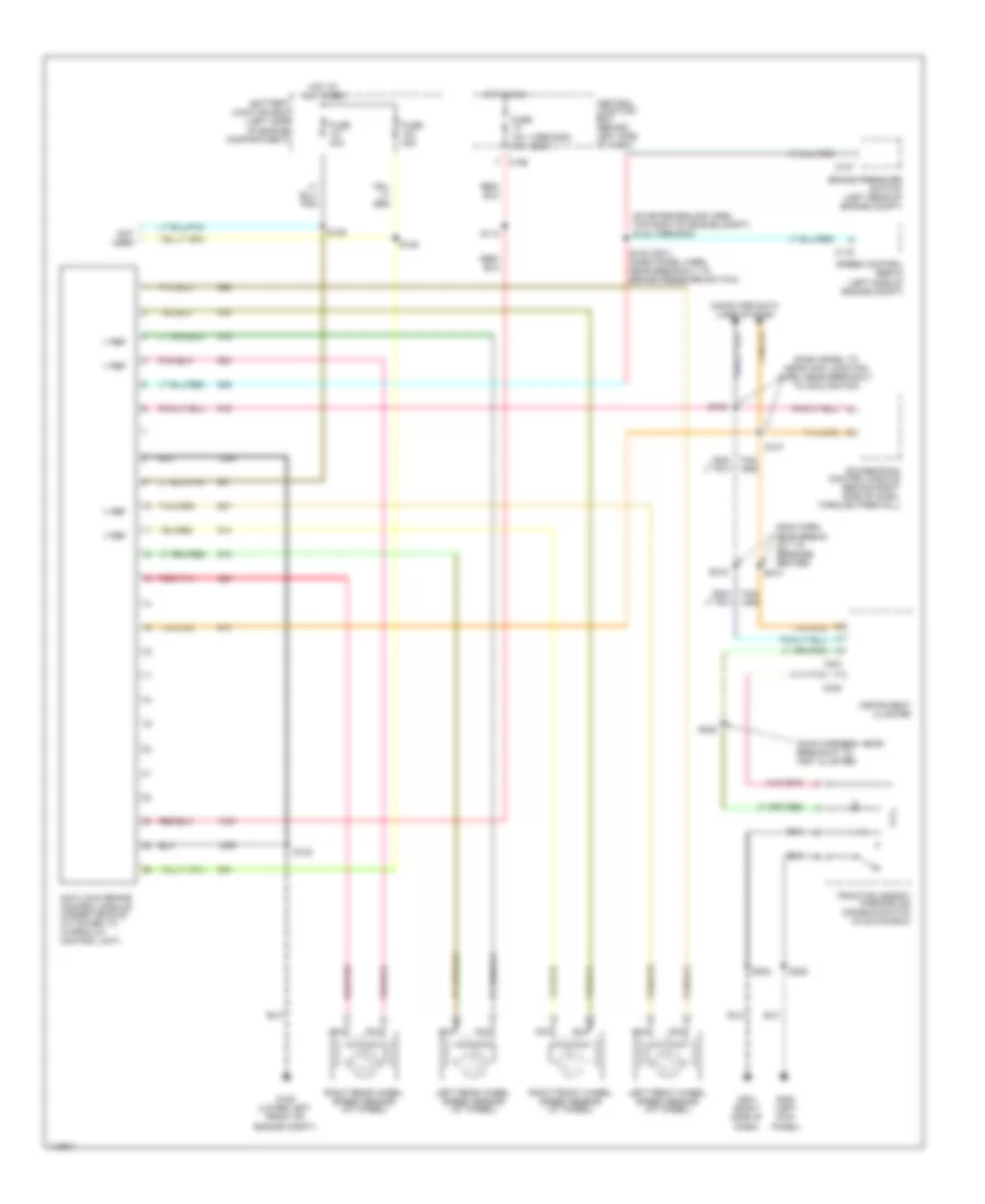
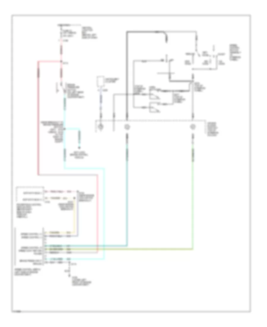
ANTI-LOCK BRAKES Anti-lock Brake Wiring Diagrams for Ford Windstar 2000 List of elements for Anti-lock Brake Wiring Diagrams for Ford Windstar 2000: 46 (1999-2000) (2001) (dash panel to headlamp junction harn, near breakout to cooling fan) (main harn, near break- out to message center) (main harness, near breakout to inst cluster) (starter ground harn, top right of engine compt) s142 (1999-2000) Anti-lock brake control module (under vehicle, attached to hydraulic control unit) Battery junction box (left side of engine compartment) Brake pressure switch (left rear of engine compt) C116 C127 C195 C240 C241 Central junction box (behind left side of dash) Computer data lines system Fuse 10a 15a Fuse 40a G106 (lower left front of engine compt) G200 (left kick panel) G201 (right side of dash) Hot at all times Hot in run Instrument cluster Left front wheel speed sensor (at wheel) Left rear wheel speed sensor (at wheel) Nca Not used Powertrain control module (behind right side of dash, through firewall) Red/pnk Right front wheel speed sensor (at wheel) Right rear wheel speed sensor (at wheel) S112 S122 (2001) (dash panel harn, near breakout to brake pressure switch) S128 S129 S132 S137 S138 S202 S214 S215 S220 S222 Speed control servo (left side of engine compt) Traction assist/ parking aid disable switch (in glove box) V ref
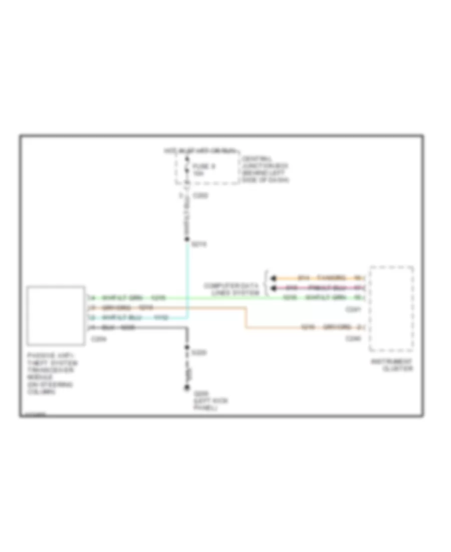
ANTI-THEFT Passive Anti-theft Wiring Diagram for Ford Windstar 2000 List of elements for Passive Anti-theft Wiring Diagram for Ford Windstar 2000: 13 C202 C204 C240 C241 Central junction box (behind left side of dash) Computer data lines system Fuse 9 10a G200 (left kick panel) Hot in start or run Instrument cluster Passive anti- theft system transceiver module (on steering column) S216 S220
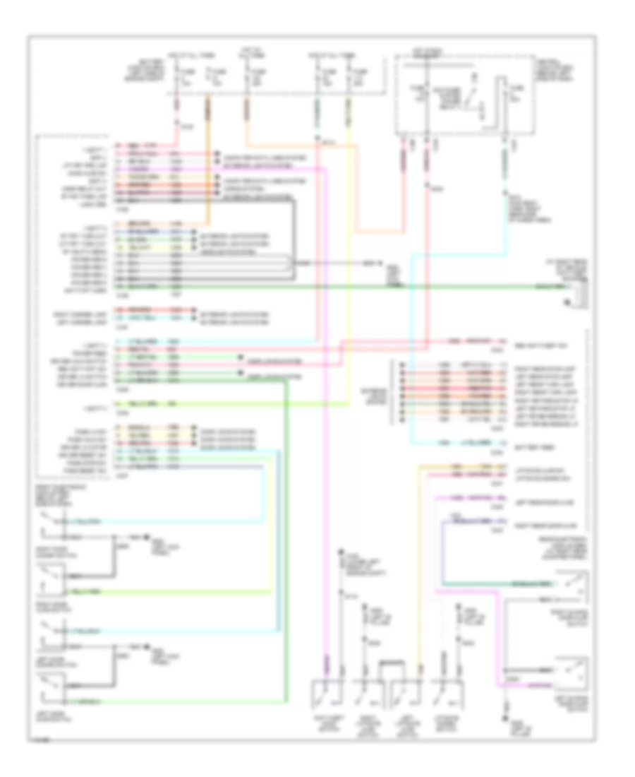
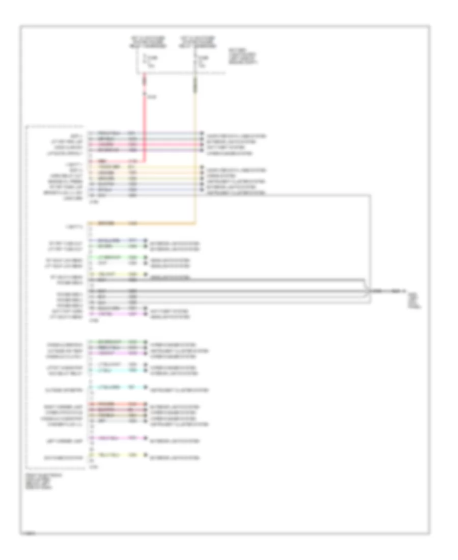
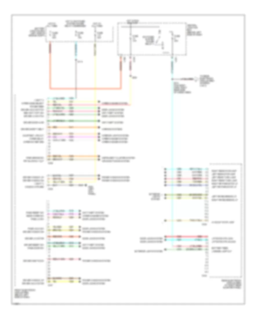
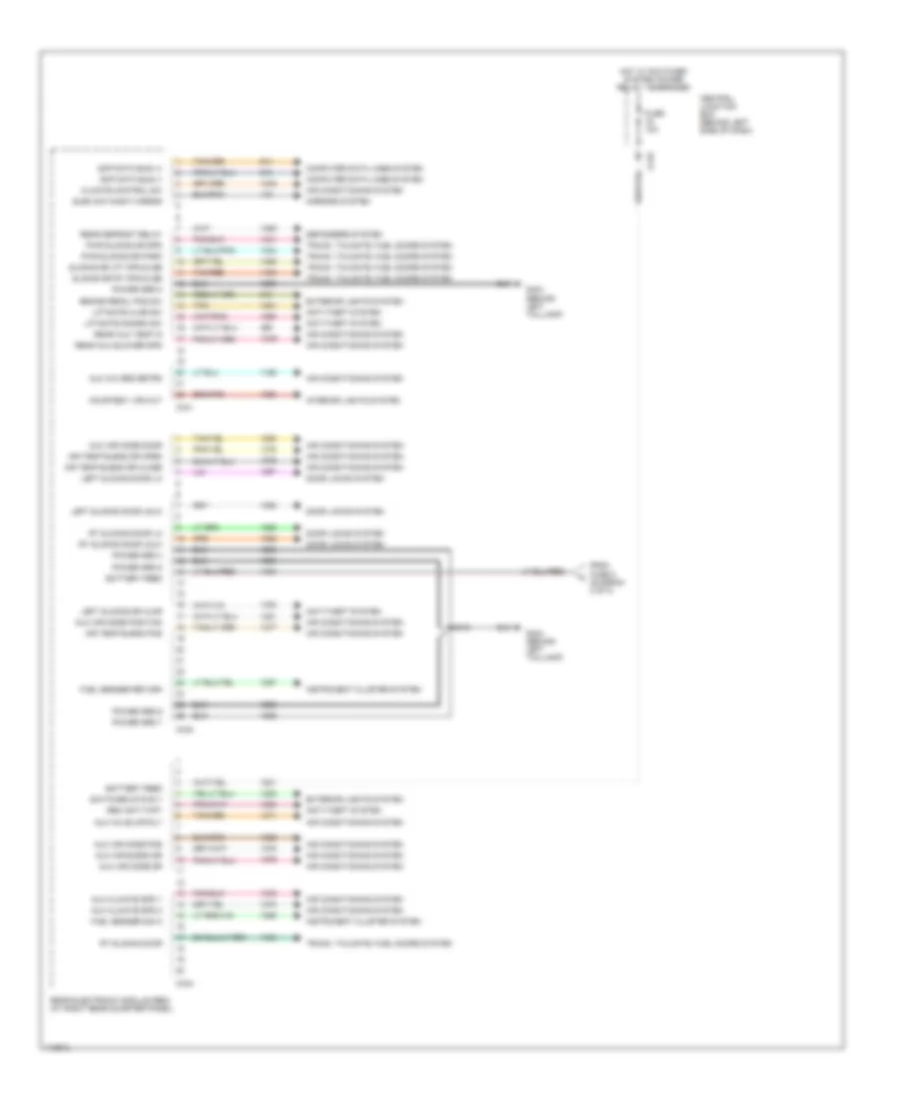
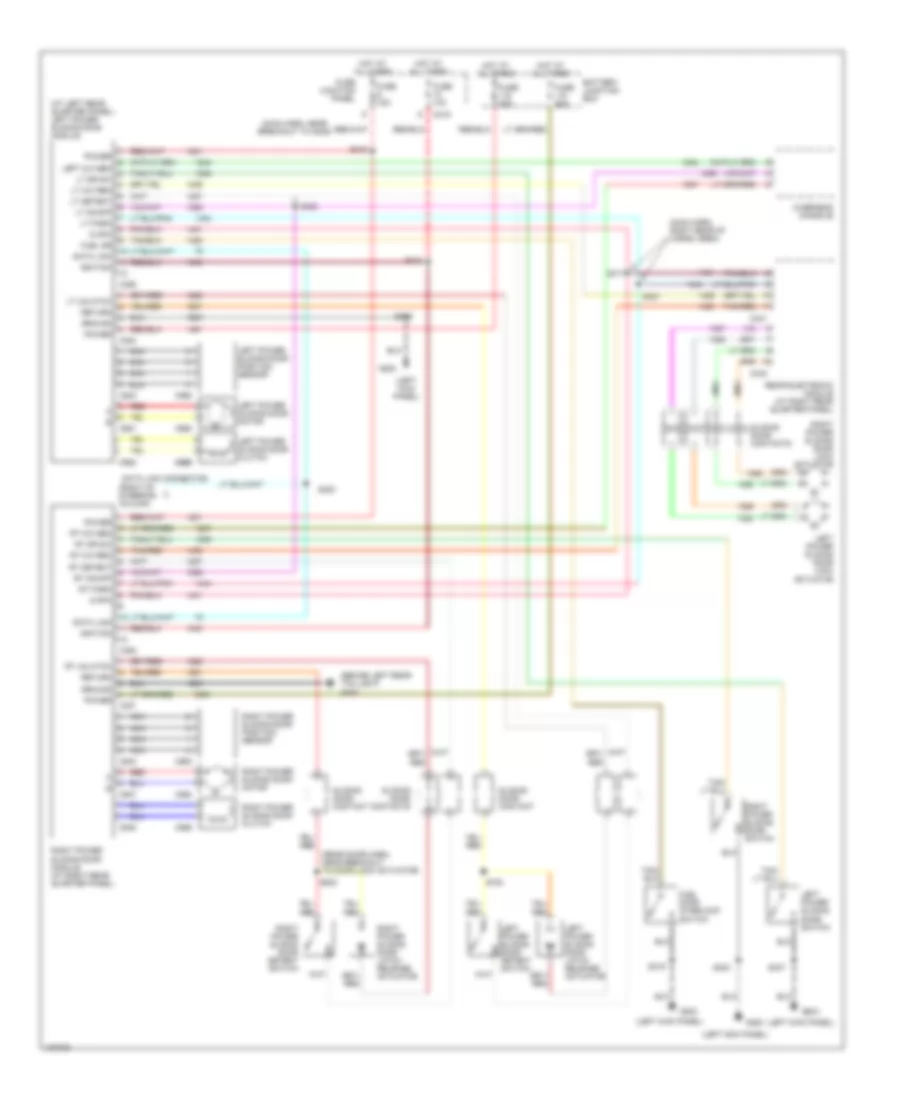
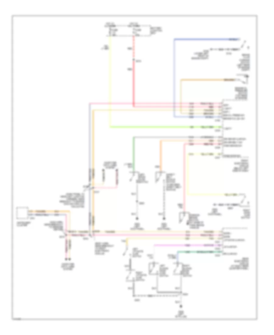
BODY COMPUTER Body Computer Wiring Diagrams (1 of 3) for Ford Windstar 2000 List of elements for Body Computer Wiring Diagrams (1 of 3) for Ford Windstar 2000: 55 Acc delay relay Anti-theft system Anti-thft horn Battery junction box (left side of engine compt) Brake fluid lvl sw C190 C191 C192 Computer data lines system Engine oil press Exterior lights system Front electronic module (fem) (below left side of dash) Fuse 10a G200 (left kick panel) Headlights system Hood ajar sw Horn relay out Horns system Hot w/ switched system power relay 1 energized Hot w/ switched system power relay 4 energized Instrument cluster system Interior lights system Left corner lamp Lft frt prk lmp Lft frt turn out Lft hdlp hi beam Lft hdlp low beam Liftgate wpr rly Liftgt washr pmp Logic grd Outside air retrn Outside air temp Power grd 3 Power grd 4 Power grd 5 Power grd 6 Red Right corner lamp Rt frt park lmp Rt frt turn out Rt hdlp hi beam Rt hdlp low beam S130 S139 Scp (+) Scp (-) Switched sys pwr V batt 1 V batt 2 Washer fluid lvl Wiper mtr status Wiper/washer system Wndshld brk/run Wndshld hi/lo rly Wndshld washr pmp Body Computer Wiring Diagrams (2 of 3) for Ford Windstar 2000 List of elements for Body Computer Wiring Diagrams (2 of 3) for Ford Windstar 2000: 77 Air conditioning system Anti-theft system Battery feed Battery junction box (left side of engine compt) C196 C219 C221 C340 C344 C346 C347 C348 Central junction box (behind left side of dash) Courtesy lps out Door locks system Driver door ajar Driver lk motor Driver lk switch Driver one-touch Driver reset sw Driver safety belt Driver unlk motor Driver unlk switch Driver window dn Driver window up Exterior lights system Front electronic module (fem) (below left side of dash) Frt blwr rly out Fuse 10a Fuse 15a Fuse 20a Fuse 30a Fuse 40a G200 (left kick panel) Hi mount stop lamp Hot at all times Hot in run or start Hot w/ switched system power relay 2 energized Instrument cluster system Interior lights system Left rear stoplamp Left rear turn lamp Left rr park/stop lp Left rr reversing lp License lamp out Liftgate mtr lock Liftgate mtr unlock Park brake sw Pass door sw Pass lk sw Pass reset sw Pass unlk sw Power feed Power windows system Rear electronic module (rem) (at right rear quarter panel) Rear wiper sw Red Red/pnk Rem anti-thft sw Right rear stoplamp Right rear turn lamp Right rr park/stop lp Right rr reversing lp S114 S313 (main body harn, right rear side of cargo area) S330 Switched system power relay 4 Tan/red To rear electronic module (rem) (diagram 3 of 3) V batt 3 V batt 4 Warning systems Window mtr grd Wiper delay Wiper mode select Wiper sw ref grd Wiper/washer system Body Computer Wiring Diagrams (3 of 3) for Ford Windstar 2000 List of elements for Body Computer Wiring Diagrams (3 of 3) for Ford Windstar 2000: 66 Air conditioning system Air temp blend dr close Air temp blend dr open Air temp blend pos Anti-theft system Aux a/c blwr rly Aux a/c grd retrn Aux air blend dr Aux air mode door Aux air mode dr Aux air mode pos Aux air mode position Aux climate spd 1 Aux climate spd 2 Battery feed Brake pedal pos sw C219 C341 C342 C343 Central junction box (behind left side of dash) Climate control sw Computer data lines system Courtesy lps out Defoggers system Door locks system Elec day/night mirror Exterior lights system From fuse 8 (diagram 2 of 3) Fuel sender return Fuel sender sig a Fuse 10a G404 (behind left taillamp) Hot w/ switched system power relay 1 energized Instrument cluster system Interior lights system Left sliding door lk Left sliding door unlk Left sliding dr ajar Liftgate ajar sw Liftgate disarm sw Mirrors system Power grd 4 Power grd 5 Power grd 6 Power grd 7 Power grd 8 Pwr sliding dr park Pwr sliding dr spd Rear aux blower spd Rear aux temp in Rear defrost relay Rear electronic module (rem) (at right rear quarter panel) Rem anti-thft Rt sliding door Rt sliding door lk Rt sliding door unlk S310 Scp data bus (+) Scp data bus (-) Sliding dr lft opn/clse Sliding dr rt opn/clse Switched sys rly Tan Tan/red Trunk, tailgate, fuel doors system
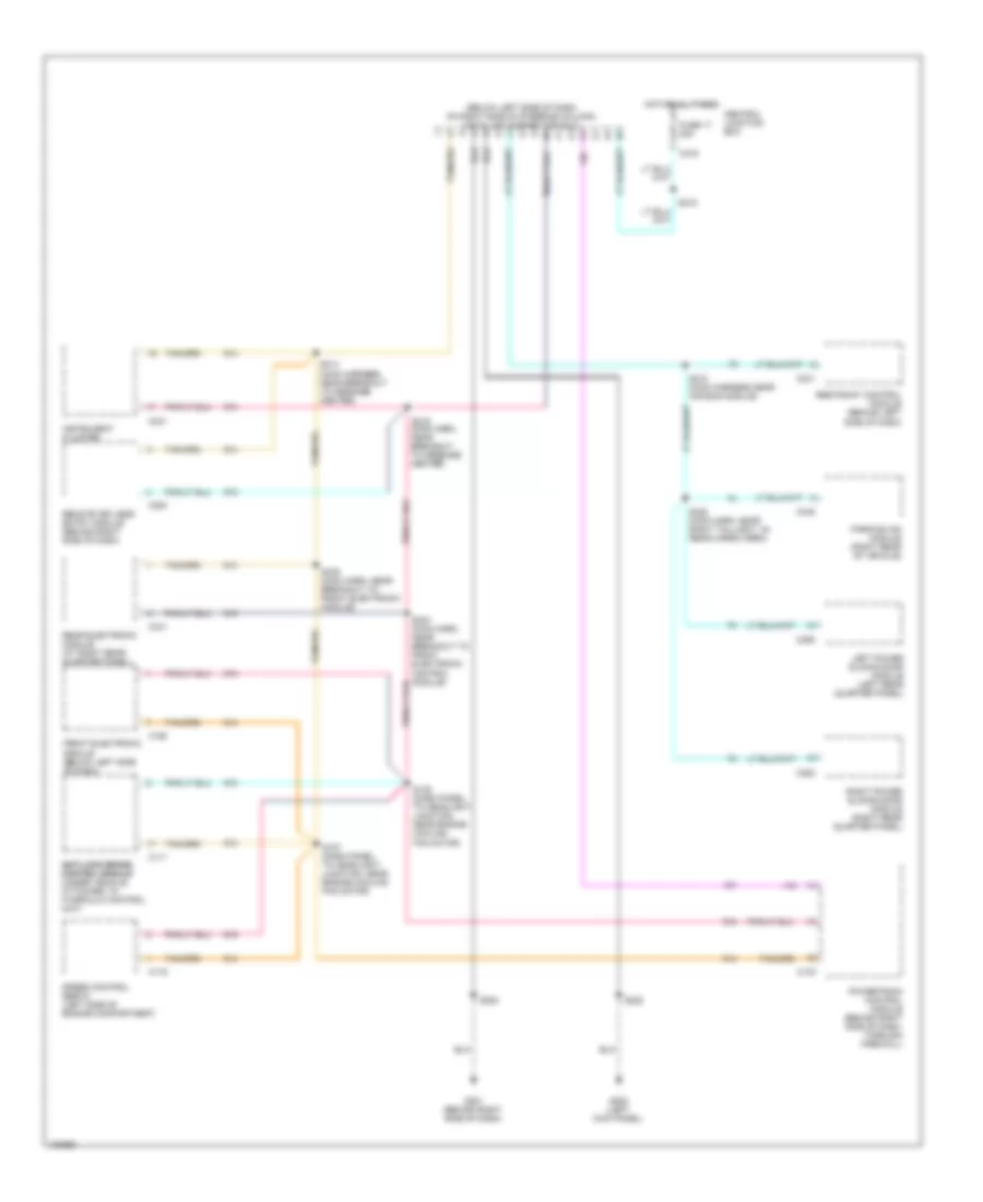
COMPUTER DATA LINES Computer Data Lines for Ford Windstar 2000 List of elements for Computer Data Lines for Ford Windstar 2000: 41 (below left side of dash, on right side of steering column) data link connector (dlc) Anti-lock brake anti-lock brake control module control module (under vehicle, attached to hydraulic control unit) C103 C111 C116 C190 C200 C219 C231 C241 C341 C352 C355 C445 Central junction box Front electronic module (below left side of dash) Fuse 17 20a G200 (left kick panel) G201 (behind right side of dash) Hot at all times Instrument cluster Left power sliding door module (left rear quarter panel) Parking aid module (right rear of vehicle) Powertrain control module (behind right side of dash, through firewall) Rear electronic module (at right rear quarter panel) Remote keyless entry module (behind right side of dash) Restraint control module (behind left Right power sliding door module (right rear quarter panel) S137 (dash panel to headlight junction, near engine cooling fan motor) S138 (dash panel to headlight junction, near engine cooling fan motor) S208 S210 (main harness near air bag module) S214 (main harness near breakout to message center) S215 (main harn, near breakout to message center) S218 S220 S320 (main harn, near right taillight, in) rear cargo area) S334 (main harn, near breakout to front electronic control module) S335 (main harn, near breakout to front electronic module) Side of dash) Speed control servo (left side of engine compartment)
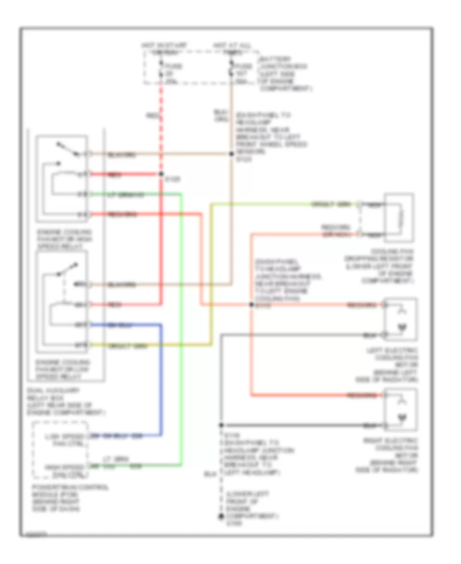
COOLING FAN Cooling Fan Wiring Diagram for Ford Windstar 2000 List of elements for Cooling Fan Wiring Diagram for Ford Windstar 2000: 20 (dash panel to headlamp harness, near breakout to left front wheel speed sensor) s123 (dash panel to headlamp junction harness, near breakout to left engine cooling fan) s113 (lower left front of engine compartment) g100 Battery junction box (left side of engine compartment) Cooling fan dropping resistor (lower left front of engine compartment) Dual auxiliary relay box (left rear side of engine compartment) Engine cooling fan motor high speed relay Engine cooling fan motor low speed relay Fuse 15a Fuse 50a High speed fan ctrl Hot at all times Hot in start or run Left electric cooling fan motor (behind left side of radiator) Low speed fan ctrl Nca Powertrain control module (pcm) (behind right side of dash) Red Right electric cooling fan motor (behind right side of radiator) S125
CRUISE CONTROL Cruise Control Wiring Diagram for Ford Windstar 2000 List of elements for Cruise Control Wiring Diagram for Ford Windstar 2000: 43 (1999-00) (2001) (2001) (1999-00) (near breakout to brake pressure switch) s122 s142 (in top right of engine compt) (top of steering wheel) s276 15a Accel Air bag sliding contact (top of steering column) Anti-lock brake control module Brake press input Brake pressure switch (on left rear of engine compartment) C103 C195 C239 Central junction box (behind left side of dash) Coast Fuse 10 10a G106 (lower left front of engine compartment) Ground Horn switches Hot in run Instrument cluster Nca Off Ohms Power Powertrain control module (pcm) (behind right side of dash, through firewall) Resume S112 S115 S137 (near engine cooling fan breakout) S138 (near engine cooling fan breakout) S275 (top of steering wheel) S277 (top of steering wheel) Scp data bus (+) Scp data bus (-) Set/ Speed cont return Speed control (+) Speed control (-) Speed control in Speed control servo (left side of engine compartment) Speed control switch assembly (in steering wheel)
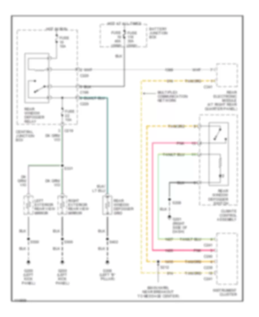
DEFOGGERS Defogger Wiring Diagram for Ford Windstar 2000 List of elements for Defogger Wiring Diagram for Ford Windstar 2000: 36 (1999) (2000) (main harn, near breakout to message center) Battery junction box C196 C219 C220 C239 C240 C241 C341 Central junction box Climate control assembly Fuse 10a Fuse 30a Fuse 40a G200 (left kick panel) G201 (right side of dash) G308 (left "b" pillar) Hot at all times Hot in run Instrument cluster Left exterior rear view mirror Multiplex communication network Pnk Rear electronic module (at right rear quarter panel) Rear window defogger grid Rear window defogger relay Rear window defogger switch Right exterior rear view mirror S208 S212 S331 S402 S500 S600
ENGINE PERFORMANCE
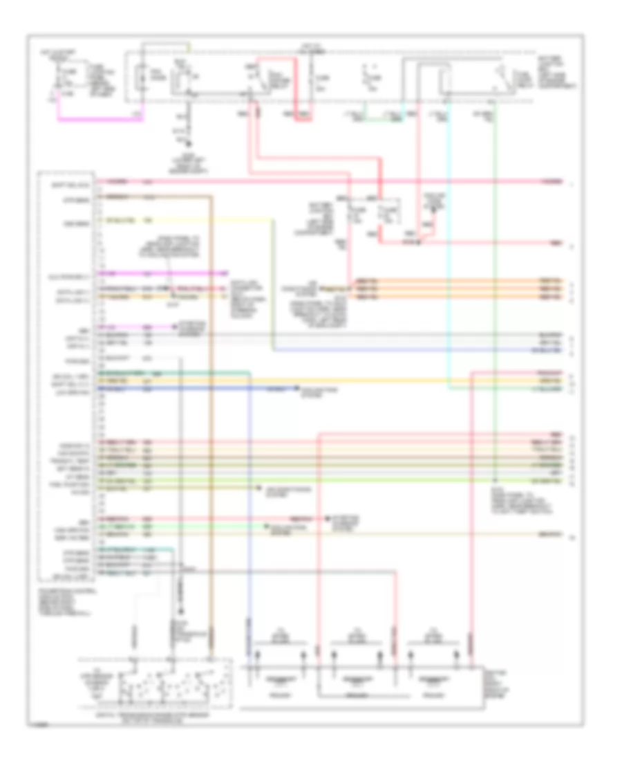
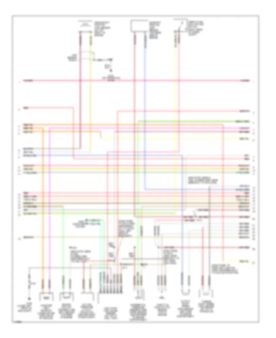
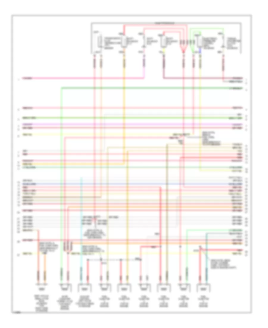
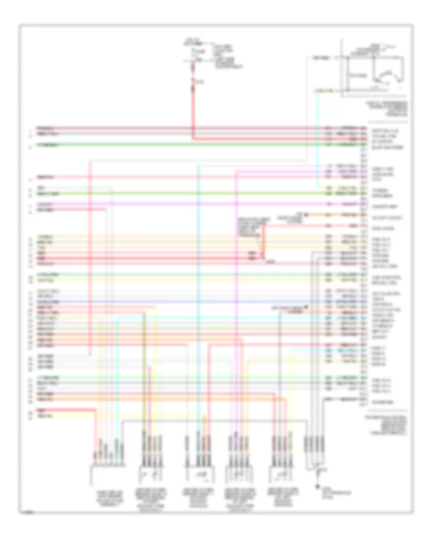
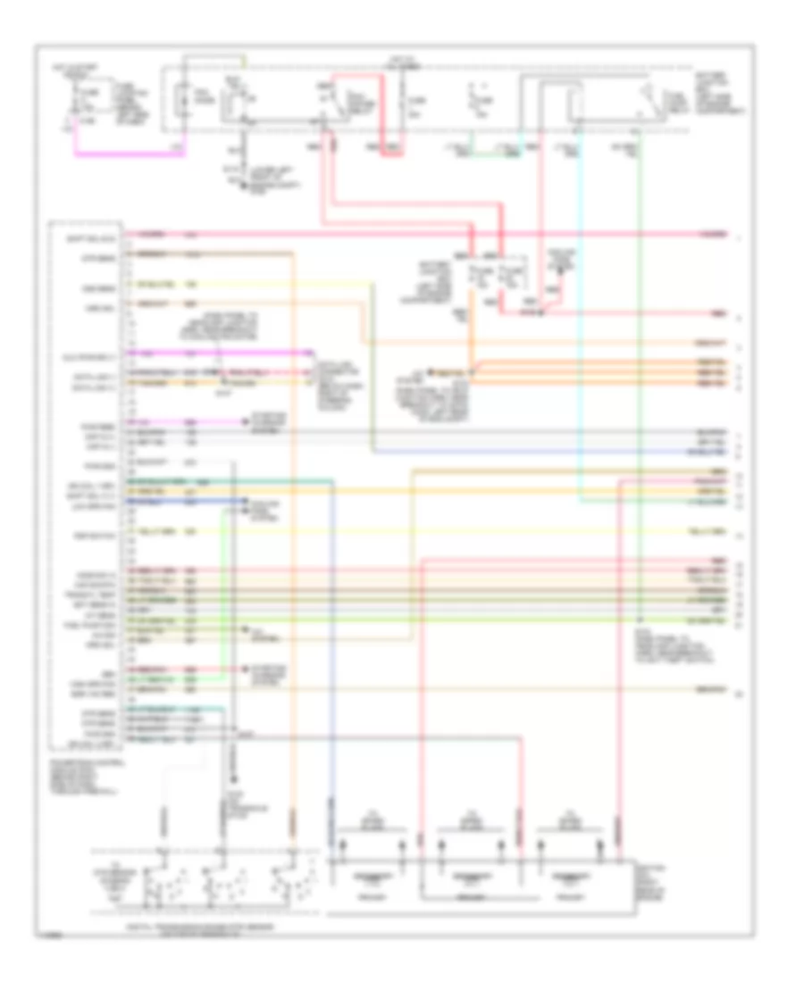
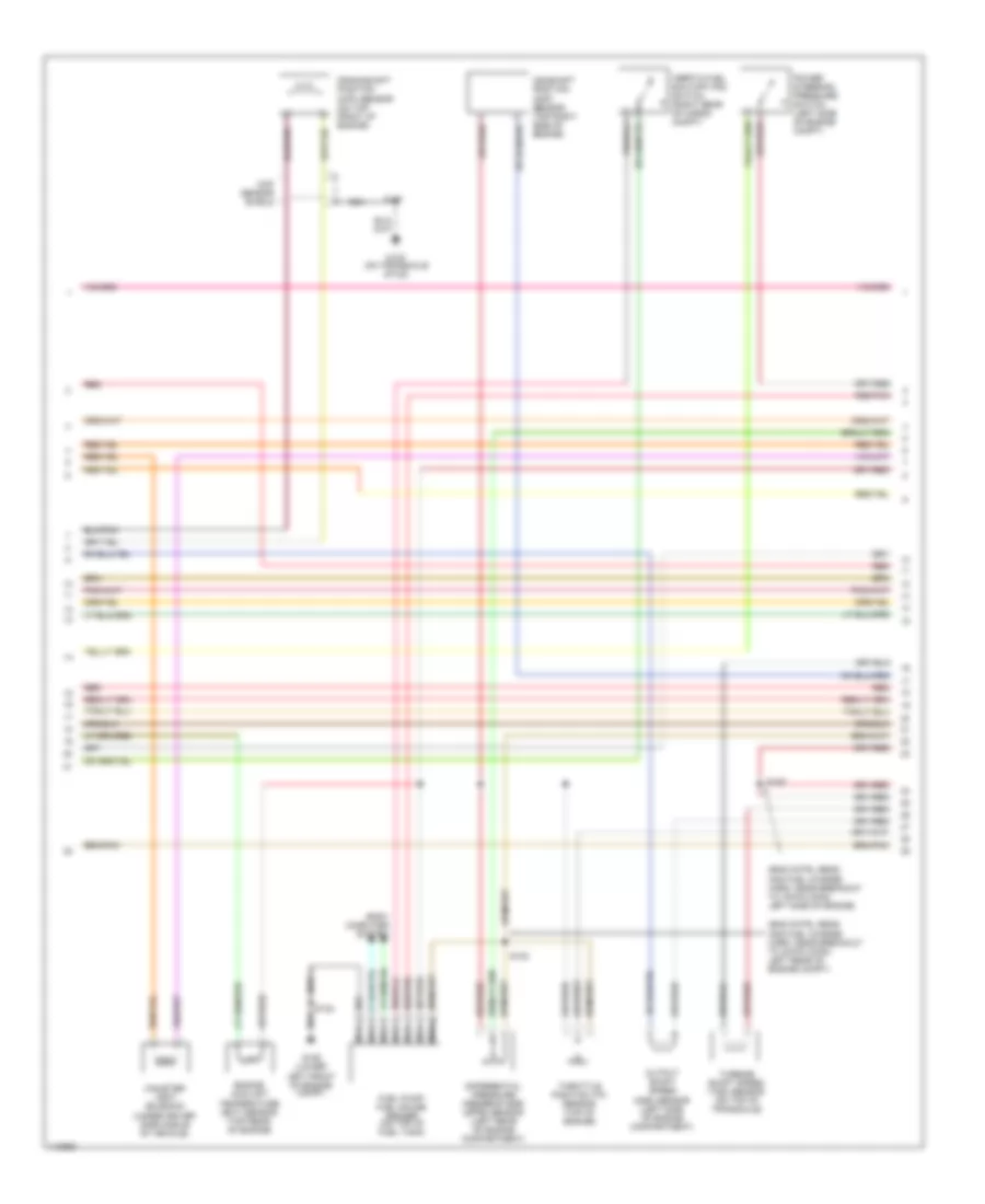
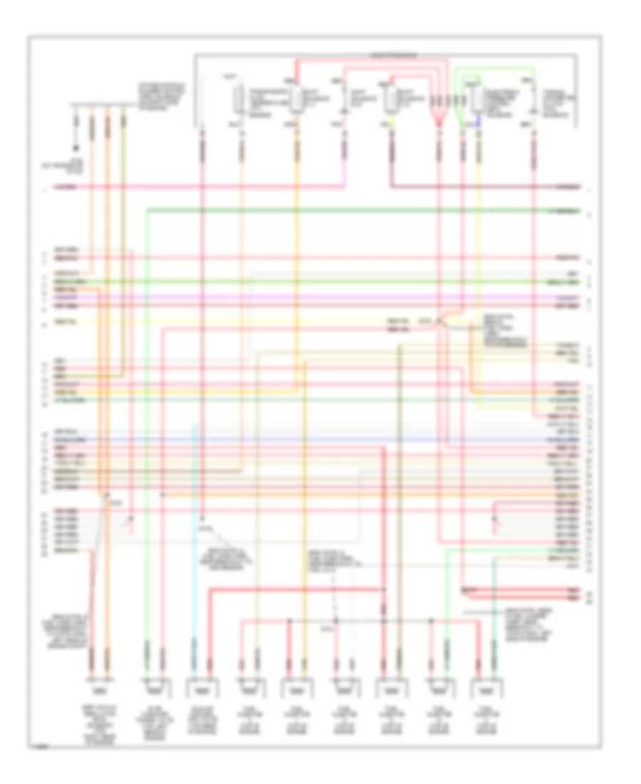
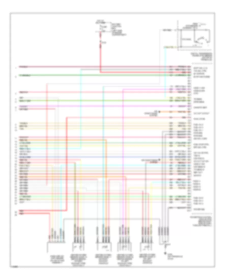
3.0L 3.0L, Engine Performance Wiring Diagrams (1 of 4) for Ford Windstar 2000 List of elements for 3.0L, Engine Performance Wiring Diagrams (1 of 4) for Ford Windstar 2000: 58 (dash panel to headlamp junction harn, near breakout to cooling fan motor) A/c sig Air conditioning system Battery junction box (left side of engine compartment) C195 Ckp in (+) Ckp in (-) Cooling fans system Data link (+) Data link (-) Data link connector (dlc) (below dash, right of steering column) Digital transmission range (dtr) sensor (on top of transaxle) Dlc (pwr sply) Dtr sens Ect sens in Egr vac reg Fuel pump mon Fuel pump relay Fuse 10a Fuse 15a Fuse 30a Fuse junction panel (behind left side of dash) G106 (lower left front of engine compt) G130 (on transaxle stud) Gen High spd fan Ho2s sig 12 Hot at all times Hot in start or run Iat sens Ign coil 1 drv Ign coil 2 drv Ignition coil (right front of engine) Low spd fan Maf sig rtn Oss sens Pcm diode Pcm power relay Powertrain control module (pcm) (behind right side of dash, through firewall) Primary Pwr gnd R n Red Red/pnk S107 S115 S125 S133 (dash panel to hdlp junction harn, near breakout to 42-pin conn, left rear of eng compt) S134 (dash panel to headlamp junction harn, near breakout to anti theft switch) S137 S138 Secondary Shift sol a (1) Shift sol b (2) Starting/ charging system To dtr sensor (diagram 4 of 4) To spark plugs Trans fl temp 3.0L, Engine Performance Wiring Diagrams (2 of 4) for Ford Windstar 2000 List of elements for 3.0L, Engine Performance Wiring Diagrams (2 of 4) for Ford Windstar 2000: 30 (dash panel to hdlp harn, near break- out to 42-pin conn, left rear of eng compt) (dash panel to hdlp harn, near breakout to left head lamp conn) (dash panel to headlamp junction harn, near breakout to cooling fan motor) (eng cntrl sens & fuel charge harn, near breakout to fuel inj 4) (eng cntrl sens & fuel charge harn, near breakout to pcm conn) (right rear of cargo compt) A/c high pressure cutout/ fan switch (center front of eng compt) Body computer system Camshaft position (cmp) sensor (top rear side of engine) Canister vent solenoid (under driver side middle of vehicle) Ckp sensor shield Crankshaft position (ckp) sensor (on top front of engine) Differential pressure feedback egr (dpfe) sensor (center rear of engine compartment) Engine coolant temperature (ect) sensor (top rear of engine) Fuel pump/ fuel gauge sender (on top of fuel tank) G106 (lower left front of eng compt) G130 (on transaxle stud) Inertia fuel shutoff (ifs) switch Nca Output shaft speed (oss) sensor (left side of engine compartment) Red Red/pnk S106 S107 S117 S131 S132 S138 Throttle position (tp) sensor (top of engine) Turbine shaft speed (tss) sensor (on top of transaxle) 3.0L, Engine Performance Wiring Diagrams (3 of 4) for Ford Windstar 2000 List of elements for 3.0L, Engine Performance Wiring Diagrams (3 of 4) for Ford Windstar 2000: 24 (eng cntrl & fuel chrg harn, near breakout to fuel inj 1) (eng cntrl & fuel chrg harn, near breakout to fuel inj 2) (eng cntrl & fuel chrg harn, near breakout to oss sensor) (eng cntrl sens & fuel charge harn, top right side of engine compt) (eng cntrl sens & fuel chrg harn, near breakout to dtr sensor) Ax4s transaxle Egr vacuum regulator (evr) solenoid (top right side of engine) Electronic pressure control (epc) solenoid Evap canister purge valve (top right side of engine) Fuel injector (top of engine) Idle air control (iac) valve (top right rear of engine) Pnk Red Red/pnk S101 S103 S104 S105 Shift solenoid a (1) Shift solenoid b (2) Shift solenoid c (3) Tan Torque converter clutch (tcc) solenoid Transmission fluid temperature (tft) sensor 3.0L, Engine Performance Wiring Diagrams (4 of 4) for Ford Windstar 2000 List of elements for 3.0L, Engine Performance Wiring Diagrams (4 of 4) for Ford Windstar 2000: 57 (eng cntrl sens & fuel charge harn, near front of transaxle) 270 ohms A/c cut out sw A/c wot cutout Air conditioning system B+ (kapwr) Battery junction box (left side of engine compartment) Cam pos in Canistr vent Digital transmission range (dtr) sensor (on top of transaxle) Dpfe sens Epc sol ctrl Evap can purge From dtr sensor (diagram 1 of 4) Ftpt Fuel inj 1 Fuel inj 2 Fuel inj 3 Fuel inj 4 Fuel inj 5 Fuel inj 6 Fuel pump ctrl Fuse 10a G106 (on transaxle stud) Heated oxygen sensor (ho2s) 11 (on right exhaust manifold) Heated oxygen sensor (ho2s) 12 (behind engine, on right exhaust pipe) (calif only) Heated oxygen sensor (ho2s) 21 (on left exhaust manifold) Heated oxygen sensor (ho2s) 22 (behind engine, on left exhaust pipe) (calif only) Ho2s 11 Ho2s 11 sig Ho2s 12 Ho2s 21 Ho2s 21 sig Ho2s 22 Ho2s 22 sig Hot at all times Iac valve ctrl Ign coil 3 drv Maf sens in Mass airflow (maf) sensor (on air intake assembly) Nca Power gnd Powertrain control module (pcm) (behind right side of dash, through firewall) Pwr (vpwr) Pwr gnd Red Red/pnk Ref volt S108 S130 Shift sol c (3) Sig rtn Tan Tcc sol ctrl Tp sens in Tr sens Tss in
3.8L 3.8L, Engine Performance Wiring Diagrams (1 of 4) for Ford Windstar 2000 List of elements for 3.8L, Engine Performance Wiring Diagrams (1 of 4) for Ford Windstar 2000: 61 (dash panel to headlamp junction harn, near breakout to cooling fan motor) (lower left front of engine compt) g106 A/c sig A/c system Battery junction box (left side of engine compartment) C195 Ckp in (+) Ckp in (-) Cooling fans system Data link (+) Data link (-) Data link connector (dlc) (below dash, right of steering column) Digital transmission range (dtr) sensor (on top of transaxle) Dlc (pwr sply) Dtr sens Ect sens in Egr vac reg Fuel pump mon Fuel pump relay Fuse 10a Fuse 15a Fuse 30a Fuse junction panel (behind left side of dash) G130 (on transaxle stud) Gen High spd fan Ho2s sig 12 Hot at all times Hot in start or run Iat sens Ign coil 1 drv Ign coil 2 drv Ignition coil (right rear of engine) Imrc sol Low spd fan Maf sig rtn Oss sens Pcm diode Pcm power relay Powertrain control module (pcm) (behind right side of dash, through firewall) Primary Psp switch Pwr feed Pwr gnd R n Red Red/pnk S107 S115 S125 S133 (dash panel to hdlp junction harn, near breakout to 42-pin conn, left rear of eng compt) S134 (dash panel to headlamp junction harn, near breakout to anti theft switch) S137 S138 Secondary Shift sol a (1) Shift sol b (2) Starting/ charging system To dtr sensor (diagram 4 of 4) To spark plugs Trans fl temp 3.8L, Engine Performance Wiring Diagrams (2 of 4) for Ford Windstar 2000 List of elements for 3.8L, Engine Performance Wiring Diagrams (2 of 4) for Ford Windstar 2000: 24 (eng cntrl sens and fuel charge harn, near breakout to 16-pin conn, left side of engine) (eng cntrl sens and fuel charge harn, near breakout to 42-pin conn, left rear of engine compt) Body computer system Camshaft position (cmp) sensor (top right side of engine) Canister vent solenoid (under driver side middle of vehicle) Ckp sensor shield Crankshaft position (ckp) sensor (on top front of engine) Differential pressure feedback egr (dpfe) sensor (left rear of engine compartment) Engine coolant temperature (ect) sensor (top rear of engine) Fuel pump/ fuel gauge sender (on top of fuel tank) G106 (lower left front of engine compt) G130 (on transaxle stud) Inertia fuel shutoff (ifs) switch (right rear of cargo compt) Nca Output shaft speed (oss) sensor (left side of engine compartment) Power steering pressure switch (left side of engine compt) Red Red/pnk S102 S106 S107 S132 Throttle position (tp) sensor (top of engine) Turbine shaft speed (tss) sensor (on top of transaxle) 3.8L, Engine Performance Wiring Diagrams (3 of 4) for Ford Windstar 2000 List of elements for 3.8L, Engine Performance Wiring Diagrams (3 of 4) for Ford Windstar 2000: 27 (eng cntrl & fuel chrg harn, near breakout to 42-pin conn, left rear of engine compt) (eng cntrl & fuel chrg harn, near breakout to fuel inj 1) (eng cntrl & fuel chrg harn, near breakout to oss sensor) (eng cntrl sens & fuel charge harn, near breakout to 16 pin conn, left side of engine) (eng cntrl sens & fuel chrg harn, near breakout to dtr sensor) Ax4s transaxle Egr vacuum regulator (evr) solenoid (top right rear of engine) Electronic pressure control (epc) solenoid Evap canister purge valve (top left rear of engine) Fuel injector (top of engine) G130 (on transaxle stud) Idle air control (iac) valve (top rear of engine) Intake manifold runner control (imrc) solenoid (on right side of engine) Pnk Red Red/pnk S100 S101 S103 S105 S144 Shift solenoid a (1) Shift solenoid b (2) Shift solenoid c (3) Tan Torque converter clutch (tcc) solenoid Transmission fluid temperature (tft) sensor 3.8L, Engine Performance Wiring Diagrams (4 of 4) for Ford Windstar 2000 List of elements for 3.8L, Engine Performance Wiring Diagrams (4 of 4) for Ford Windstar 2000: 55 270 ohms A/c cut out sw A/c wot cutout Air conditioning system B+ (kapwr) Battery junction box (left side of engine compartment) Cam pos in Canistr vent Digital transmission range (dtr) sensor (on top of transaxle) Dpfe sens Epc sol ctrl Evap can purge From dtr sensor (diagram 1 of 4) Ftpt Fuel inj 1 Fuel inj 2 Fuel inj 3 Fuel inj 4 Fuel inj 5 Fuel inj 6 Fuel pump ctrl Fuse 10a G106 (on transaxle stud) Heated oxygen sensor (ho2s) 11 (on right exhaust manifold) Heated oxygen sensor (ho2s) 12 (behind engine, on right exhaust pipe) (calif only) Heated oxygen sensor (ho2s) 21 (on left exhaust manifold) Heated oxygen sensor (ho2s) 22 (behind engine, on left exhaust pipe) (calif only) Ho2s 11 Ho2s 11 sig Ho2s 12 Ho2s 21 Ho2s 21 sig Ho2s 22 Ho2s 22 sig Hot at all times Iac valve ctrl Ign coil 3 drv Maf sens in Mass airflow (maf) sensor (on air intake assembly) Nca Power gnd Powertrain control module (pcm) (behind right side of dash, through firewall) Pwr (vpwr) Pwr gnd Red Red/pnk Ref volt S130 Shift sol c (3) Sig rtn Tan Tcc sol ctrl Tp sens in Tr sens Tss in
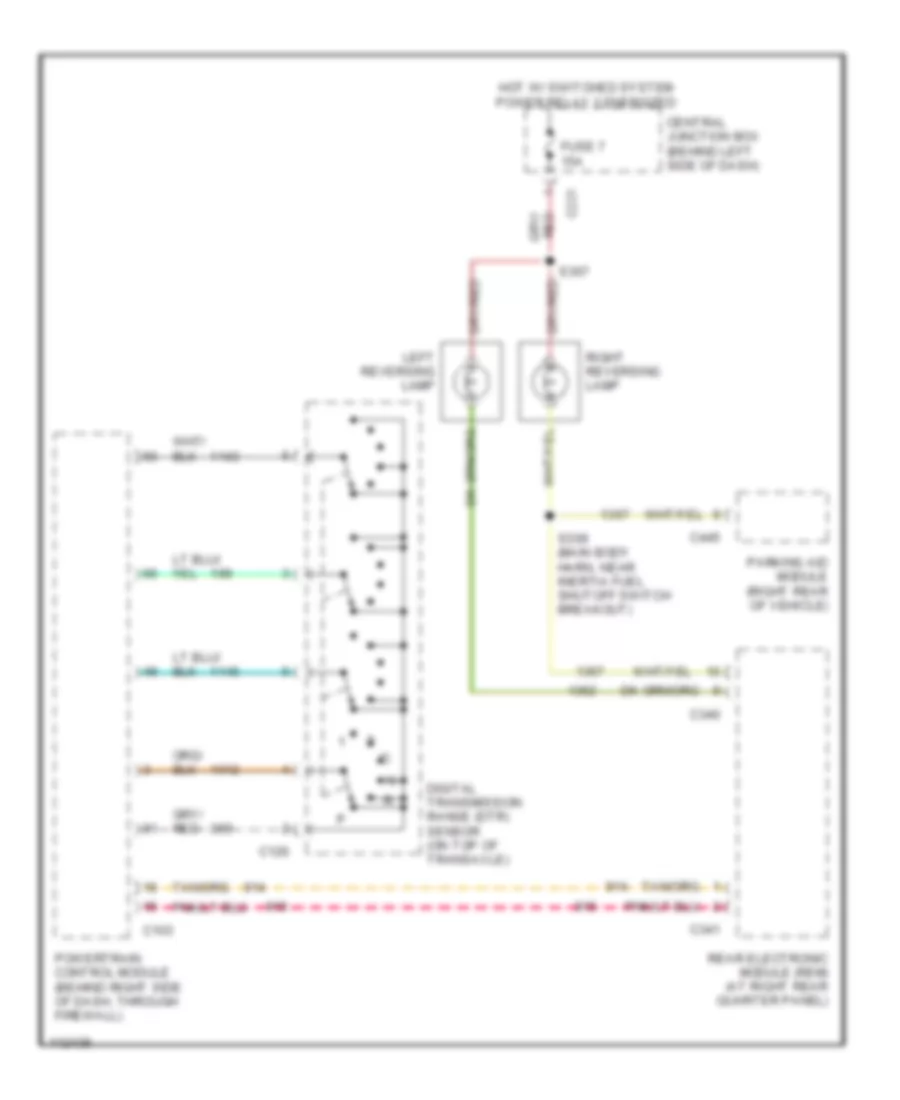
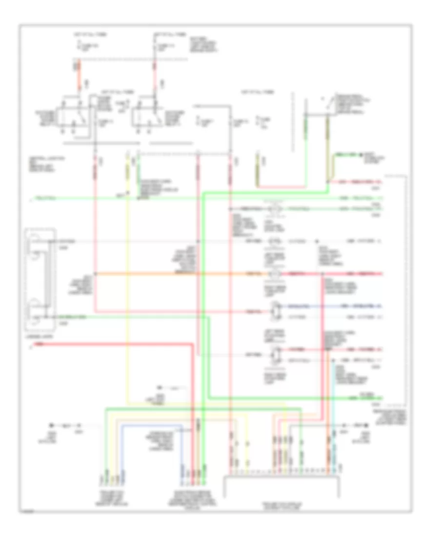
EXTERIOR LIGHTS Back-up Lamps Wiring Diagram for Ford Windstar 2000 List of elements for Back-up Lamps Wiring Diagram for Ford Windstar 2000: 17 C103 C126 C221 C340 C341 C445 Central junction box (behind left side of dash) Digital transmission range (dtr) sensor (on top of transaxle) Fuse 7 15a Hot w/ switched system power relay 3 energized Left reversing lamp Parking aid module (right rear of vehicle) Powertrain control module (behind right side of dash, through firewall) Rear electronic module (rem) (at right rear quarter panel) Right reversing lamp S307 S309 (main body harn, near inertia fuel shutoff switch breakout) Exterior Lamps & Trailer connector Wiring Diagram (1 of 2) for Ford Windstar 2000 List of elements for Exterior Lamps & Trailer connector Wiring Diagram (1 of 2) for Ford Windstar 2000: 47 (dash panel to headlamp junction, near anti-theft switch breakout) (main harness, near message center breakout) s214 (not used) Auto Battery junction box (left side of engine compt) C190 C191 C192 C239 C240 C241 C341 C346 Front electronic module (fem) (below left side of dash) Fuse 108 40a Fuse 109 40a Fuse 112 30a Fuse 22 15a Fuse 23 15a Hazard Head Hot at all times Instrument cluster Left front park/turn lamp Left front side lamp Left turn Main light switch Multi- function switch Normal Off Park Rear electronic module (rem) (at right rear quarter panel) Red Right front park/turn lamp Right front side lamp Right turn S111 (dash panel to headlamp junction, near right headlamp) S114 (dash panel to headlamp junction, near cooling fan dropping resistor) S118 S119 S120 S127 S135 S215 (main harness, near message center breakout) Switched system power relay 1 Switched system power relay 2 Tan/red Exterior Lamps & Trailer connector Wiring Diagram (2 of 2) for Ford Windstar 2000 List of elements for Exterior Lamps & Trailer connector Wiring Diagram (2 of 2) for Ford Windstar 2000: 52 (main body harn, near front electronic module breakout) s336 (main body harn, near right rear lamps grommet) s306 (parking aid sensor front harn, right rear of cargo area) Battery junction box (left side of engine compt) Brake pedal position switch (behind dash, top of brake pedal) C196 C201 C219 C221 C340 C341 C343 C344 C409 C449 Central junction box (behind left side of dash) Electronic brake switch connector (under center of dash, near restraint control module) Fuse 103 40a Fuse 10a Fuse 114 40a Fuse 12 20a Fuse 13 15a Fuse 20a Fuse 7 15a G200 (left kick panel) G308 (left 'b' pillar) High mounted stop lamp Hot at all times Left rear stop/park lamp Left rear turn/stop lamp License lamps Power distri- bution system Rear electronic module (rem) (at right rear quarter panel) Red Red/pnk Right rear stop/park lamp Right rear turn/stop lamp S217 S303 (main body harn, near body power point breakout) S304 (main body harn, near right rear lamps grommet) S305 (main body harn, near right rear lamps grommet) S307 (main body harn, near inertia fuel shutoff switch breakout) S314 (main body harn, right rear of cargo area) S316 (main body harn, right rear of cargo area) S400 S401 Shift interlock system Switched system power relay 3 Switched system power relay 4 Tan/red Trailer tow connector (under left rear of vehicle) Trailer tow module (on right 'd' pillar)
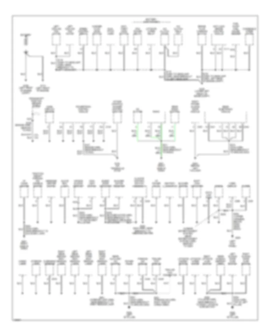
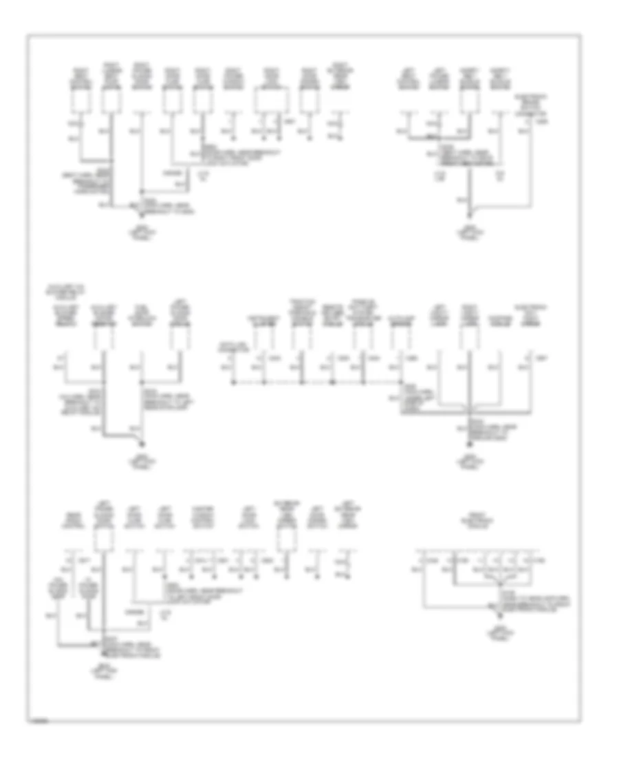
GROUND DISTRIBUTION Ground Distribution Wiring Diagram (1 of 2) for Ford Windstar 2000 List of elements for Ground Distribution Wiring Diagram (1 of 2) for Ford Windstar 2000: 101 (left kick panel) (w/rear entertainment system) (rear entertainment system harn, near b/o to c294) 3.0l 3.8l A/c clutch diode A/c clutch field coil Air bag sliding contact Anti- theft hood switch Anti-lock brake control module Ashtray illumination Battery Battery junction box Blend door actuator Blower motor resistor Blower switch Brake fluid warning switch C103 C111 C244 C341 C342 C351 C391 C395 C445 C449 C915 Cargo lamp Cd player Climate control switch assembly Crankshaft position sensor shield Data link conn Dual pitch horn Filter Front of egine compt) Fuel pump/ fuel gauge sender G106 (left front of engine compt) G106 (lower left G110 (left front of engine) G130 (on G200 G201 (right G308 (left "b" pillar) G404 (behind Glove box lamp Harn, left rear of engine compt) Harn, near breakout to left headlamp) I/p cigar lighter I/p power plug Intake manifold runner control monitor Interior lamp Left cooling fan motor Left rear second row reading lamp Left rear third row reading lamp Left sliding door ajar switch Left taillamp) Liftgate disarm switch Liftgate wiper motor Liftgate wiper relay Main light switch Mass airflow sensor Message center switch Nca Near breakout to glove box lamp) Near breakout to instrument cluster) Near breakout to radio) Near breakout to right liftgate ajar switch) Near breakout to temperature blend actuator) Overhead console Parking aid module Pcm power relay Power plug Powertrain control module Radio Rear auxiliary a/c control Rear electronic module Rear radio control Rear window defrost grid Right liftgate ajar switch Right power sliding door module Right rear second row reading lamp Right rear third row reading lamp Right sliding door ajar switch S109 (engine harn, near b/o to pcm) S208 (main harn, near breakout to message center) S232 S352 (jumper harness, behind dash, near radio) S401 (parking aid harn, right side of cargo area) S402 (tailgate harn, S901 (interior lamp harn, near breakout to right reading lamp) Shift lock actuator Side of dash) Speed control servo To left headlamp) Traction assist/ parking aid disable switch Trailer tow module Trailor tow connector Transaxle stud) Video display Washer fluid level switch Windshield wiper motor Ground Distribution Wiring Diagram (2 of 2) for Ford Windstar 2000 List of elements for Ground Distribution Wiring Diagram (2 of 2) for Ford Windstar 2000: 69 Autolamp sensor Auxiliary a/c blower relay module Auxiliary blower motor resistor Auxiliary blower speed relay 2 Breakout to drvr front vert motor) Breakout to ground g200) C190 C192 C200 C204 C240 C260 C286 C348 C501 C502 C514 C601 C907 C917 Compass module Data link connector Electronic brake switch connector Electronic day/ night mirror Electronic module) Exterior rear view mirror switch Front electronic module Fuel door interlock switch G & gl G-base G200 (left kick panel) Instrument cluster Left door ajar switch Left door disarm switch Left door lock switch Left exterior rear view mirror Left power lumbar switch Left power sliding door module Left power sliding door switch Left seat control switch Left vanity mirror lamp Lx & gl Lx & lxe Master window control switch Nca Passive anti-theft system transceiver module Rear radio control Remote keyless entry module Right door ajar switch Right door disarm switch Right door lock switch Right exterior rear view mirror Right lumbar seat pump motor Right power sliding door switch Right power window switch Right seat control switch Right vanity mirror lamp S319 (main harn, near breakout to left rear stoplamp) S323 (main harn, near breakout to g200) S337 (main harn, near breakout to front electronic module) S342 (seat harn, near breakout to passenger horiz motor) S343 (a/c harn, near breakout to auxiliary a/c relay module) S500 (door harn, near breakout to left front door lock actuator) Safety belt buckle switch Side of dash) To right front door lock actuator) Traction assist/ parking & disable switch W/ power sliding door W/o power sliding door
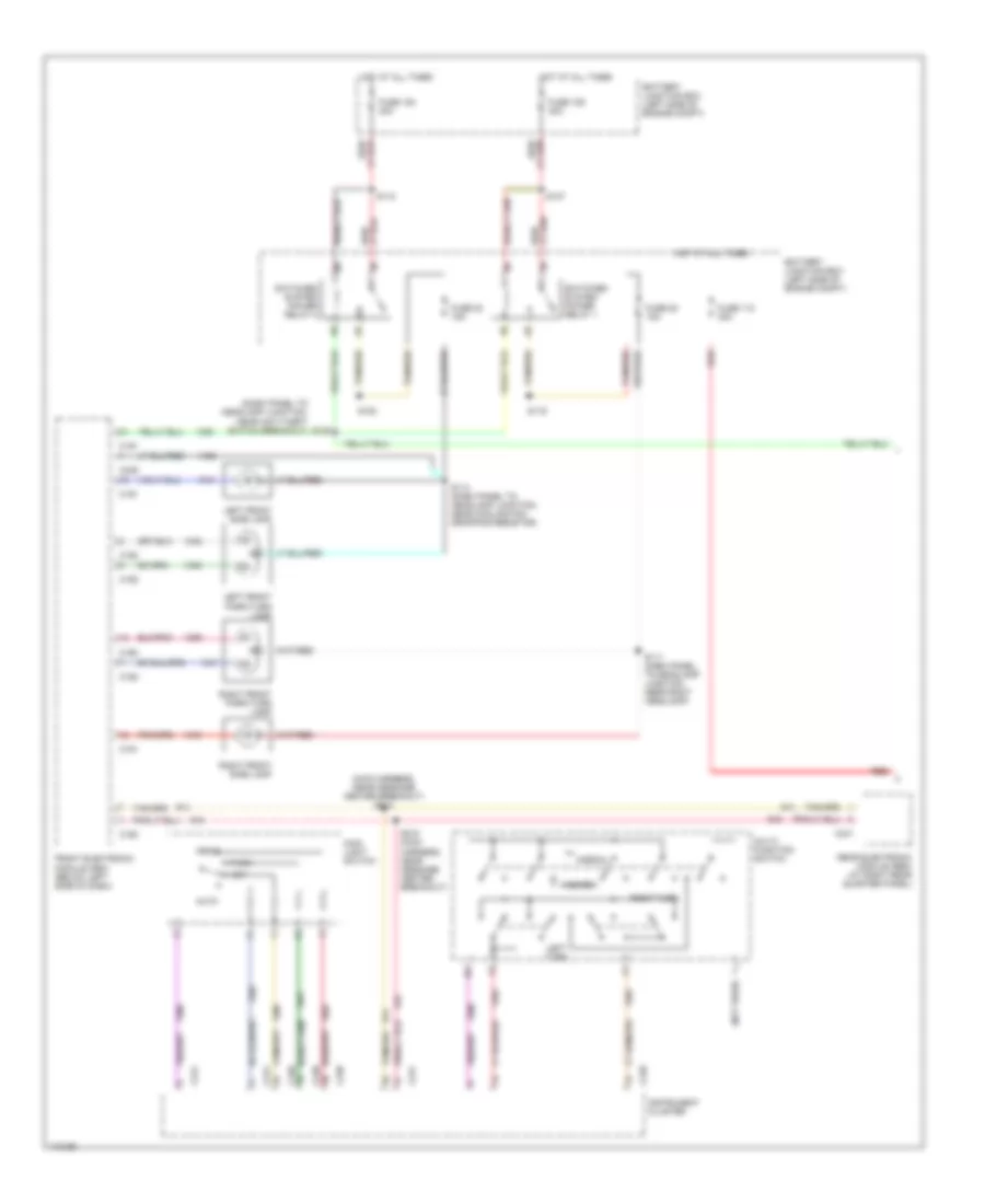
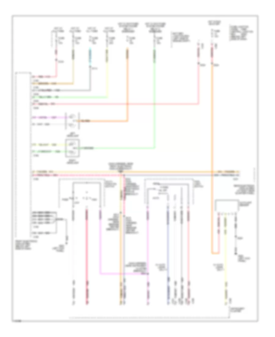
HEADLIGHTS Headlight Wiring Diagram for Ford Windstar 2000 List of elements for Headlight Wiring Diagram for Ford Windstar 2000: 51 (1999) (2000) (main harness, near front electronic module breakout) s335 (main harness, near instrument cluster breakout) s221 Auto Autolamp sensor Battery junction box (left side of engine compt) C190 C192 C202 C219 C239 C240 C241 C341 C346 C348 Front electronic module (fem) (below left side of dash) Fuse 10a Fuse 15a Fuse 30a Fuse junction panel central junction box (behind left side of dash) G200 (left kick panel) Head High Hot at all times Hot in run or start Hot w/ switched system power relay 1 energized Hot w/ switched system power relay 2 energized Instrument cluster Left headlamp Low Main light switch Multi- function switch Off Park Pass Rear electronic module (rem) (at right rear quarter panel) Red Red/pnk Right headlamp S114 S130 S139 S214 (main harness, near message center breakout) S215 (main harness, near message center breakout) S220 S224 S330 S334 (main harness, near front electronic module breakout) W/ auto lamps only
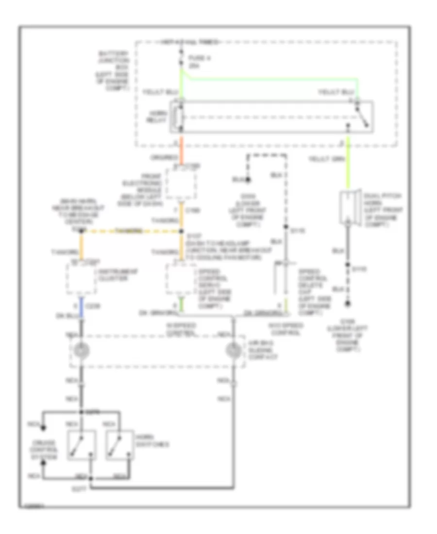
HORN Horn Wiring Diagram for Ford Windstar 2000 List of elements for Horn Wiring Diagram for Ford Windstar 2000: 27 (main harn, near breakout to message center) s214 25a Air bag sliding contact Battery junction box (left side of engine compt) C190 C239 C241 Cruise control system Dual pitch horn (left front Front electronic module (below left side of dash) Fuse 4 G106 (lower left front of engine compt) Horn relay Horn switches Hot at all times Instrument cluster Nca Of engine compt) S115 S137 S276 S277 Speed control delete cap (left side of engine compt) Speed control servo (left side of engine compt) To cooling fan motor) W/o speed control W/speed control
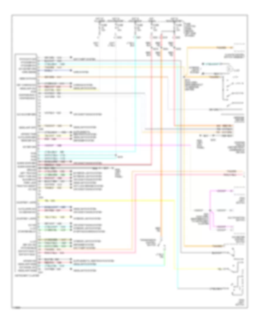
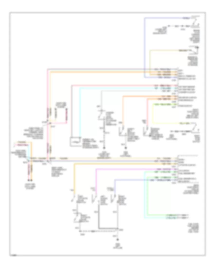
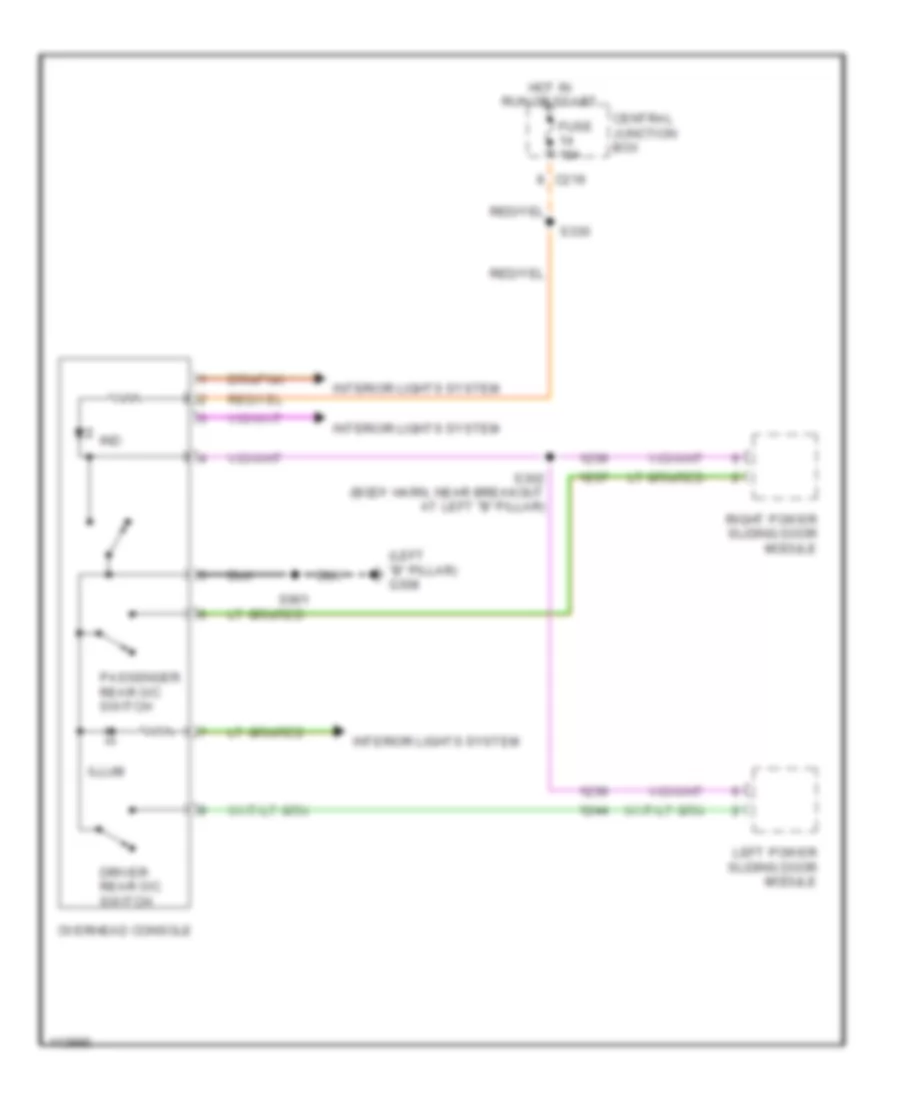
INSTRUMENT CLUSTER Instrument Cluster Wiring Diagram (1 of 2) for Ford Windstar 2000 List of elements for Instrument Cluster Wiring Diagram (1 of 2) for Ford Windstar 2000: 78 A/c demand sw A/c ind A/c-heater control switch Air bag ind Air bag tone Air conditioning system Anti-lock brakes system Anti-theft system Autolamps (on) Autolamps sen Aux blower sen Blend door ref Blend door sen Blower sw C201 C202 C219 C239 C240 C241 Climate control switch assembly Compass bus + Compass bus - Compass module (center front underside of ceiling) Courtesy lamps Def (on) ind Defogger system Exterior lights system Fuse 10a Fuse junction panel (behind left side of dash) G200 (left kick panel) Ground Headlamp (off) Headlamp (on) Headlamp mode Headlights system Horn sense Horn system Hot at all times Hot in acc or run Hot in run Hot in run or start I/p dimmer sw Illum Instrument cluster Interior lights system Key warning sw Left trun sig Main light switch Mess cntr sig Message center Multifunction switch O/d cancel sw Park lamp Pats data sig Pats enable Pnk Pwr Rear def sw Red/pnk Right turn sig S212 (main harn, near breakout to message center) S216 S219 S220 S221 (main harn, near breakout to instrument cluster) S224 S330 S333 Scp data bus + Scp data bus - Starter relay Starting/charging system Sw return Sw sig return Traction assist Transmission control switch Warning system Instrument Cluster Wiring Diagram (2 of 2) for Ford Windstar 2000 List of elements for Instrument Cluster Wiring Diagram (2 of 2) for Ford Windstar 2000: 57 (body harn, near breakout to front electronic module) (dash panel to headlight junction harness, near breakout to engine cooling high/low fan motor) (main harn, near breakout to message center) Air temp return Air temp sensor Ambient air temperature sensor (on right front of engine compt) Brake fld lev sw Brake fluid warning switch (left rear of engine compt) C190 C191 C341 C342 C343 C346 C347 Computer data lines system Driver dr ajar sw Eng oil press sw Engine oil pressure switch (top rear of engine) Front electronic module (below left side of dash) Fuel pump/ fuel gauge sender (on top of fuel tank) Fuel sender ret Fuel sender sig a G106 (lower left front of engine compt) G200 (left kick panel) G308 (left "b" pillar) Left liftgate ajar switch Left sliding door ajar switch Liftgate ajar sw Lr ajar sw Nca Park brake sw Parking brake switch (at base of park brake handle) Pass door sw Rear electronic module (at right rear quarter panel) Right door ajar switch Right liftgate ajar switch Right sliding door ajar switch Rr ajar sw S115 S132 S137 S138 S214 S215 S300 S334 S335 S600 Safety belt buckle switch (in driver's safety belt buckle) Scp + Scp - Scpb + Scpb- Tan Washer fluid level switch (in washer fluid reservoir) Washer fluid sw Overhead Console Wiring Diagram for Ford Windstar 2000 List of elements for Overhead Console Wiring Diagram for Ford Windstar 2000: 16 (left "b" pillar) g308 C219 Central junction box Driver rear o/c switch Fuse 10a Hot in run or start Illum Ind Interior lights system Left power sliding door module Overhead console Passenger rear o/c switch Right power sliding door module S302 (body harn, near breakout at left "b" pillar) S330 S901
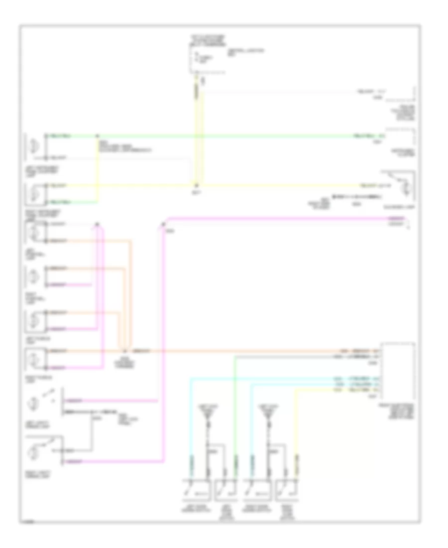
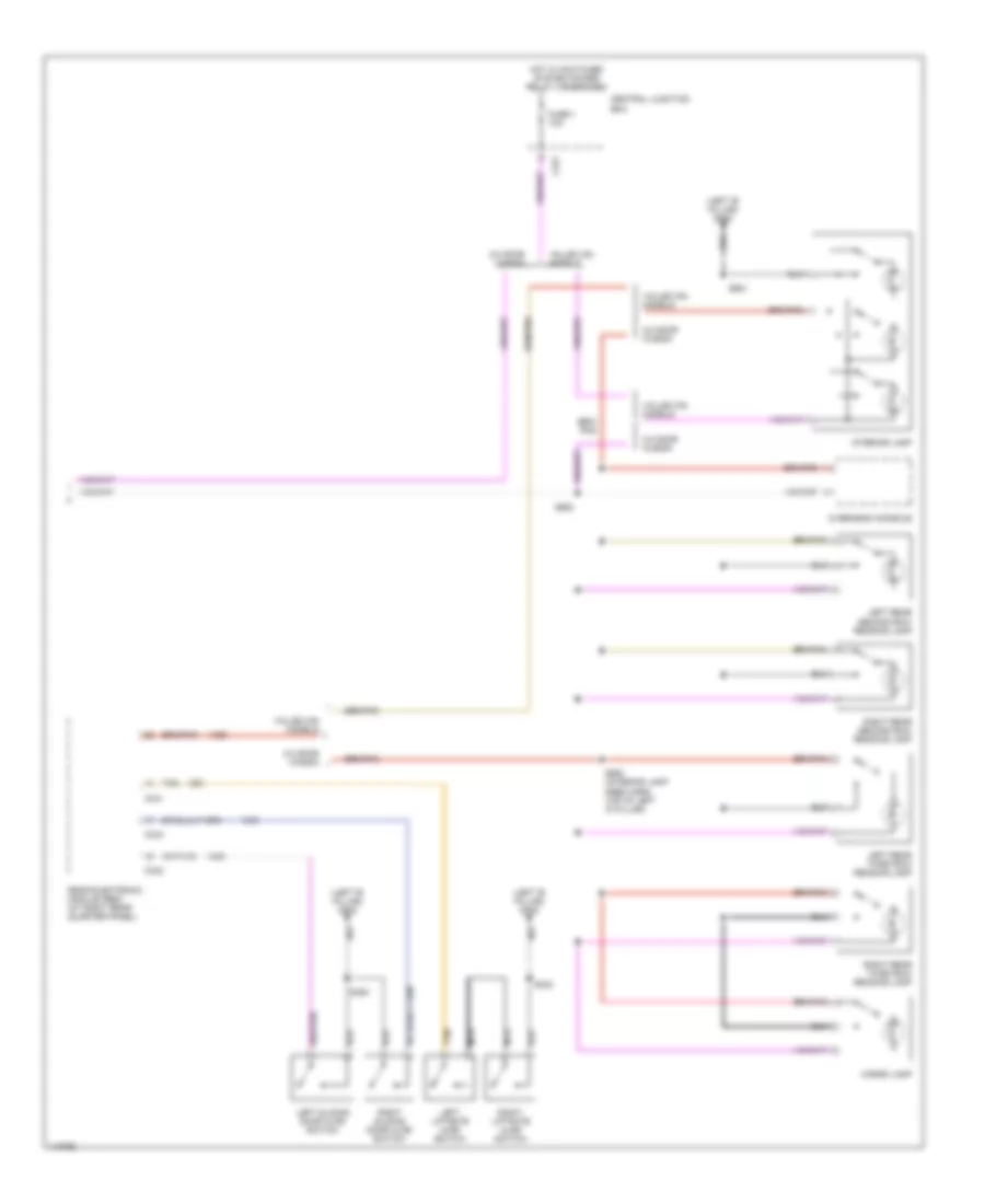
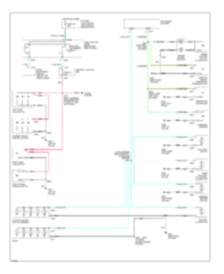
INTERIOR LIGHTS Courtesy Lamps Wiring Diagram (1 of 2) for Ford Windstar 2000 List of elements for Courtesy Lamps Wiring Diagram (1 of 2) for Ford Windstar 2000: 35 (left kick panel) g200 C201 C241 C346 C347 C449 Central junction box Front electronic module (fem) (below left side of dash) Fuse 2 20a G200 (left kick panel) G201 (right side of dash) Glove box lamp Hot w/ switched system power relay 4 energized Instrument cluster Left door ajar switch Left door disarm switch Left instrument panel courtesy lamp Left puddle lamp Left stepwell lamp Left vanity mirror lamp Right door ajar switch Right door disarm switch Right instrument panel courtesy lamp Right puddle lamp Right stepwell lamp Right vanity mirror lamp S202 S203 (main harn, near glove box lamp breakout) S217 S324 S325 (main body harness) S333 S500 S600 Trailer tow module (on right 'd' pillar) Courtesy Lamps Wiring Diagram (2 of 2) for Ford Windstar 2000 List of elements for Courtesy Lamps Wiring Diagram (2 of 2) for Ford Windstar 2000: 29 (left 'b' pillar) g308 3/4 door wagon C221 C341 C342 C343 Cargo lamp Central junction box Fuse 1 10a Hot w/ switched system power relay 3 energized Interior lamp Left liftgate ajar switch Left rear second row reading lamp Left rear third row reading lamp Left sliding door ajar switch Nca Overhead console Rear electronic module (rem) (at right rear quarter panel) Right liftgate ajar switch Right rear second row reading lamp Right rear third row reading lamp Right sliding door ajar switch S300 S402 S900 (interior lamp feed harn, top of left 'd' pillar) S901 S902 Tan Value/van models Instrument Illumination Wiring Diagram for Ford Windstar 2000 List of elements for Instrument Illumination Wiring Diagram for Ford Windstar 2000: 60 (2000) (main harness, near breakout to message center) s213 Air bag sliding contact Ashtray illumination Battery junction box (left side of engine compt) C191 C196 C211 C220 C221 C241 C244 C251 C253 C257 C280 C502 C915 C917 C930 Central junction box Climate control switch assembly Delayed accessory relay Front electronic module (below left side of dash) Fuse 106 30a Fuse 18 10a Fuse junction panel (behind left side of dash) G200 (left kick panel) G201 (right side of dash) G308 (left "b" pillar) Hot at all times Illum Instrument cluster Left door lock switch Main light switch Master window control switch Message center switch Nca Overhead console Pnk Radio Rear auxiliary a/c control illumination Rear radio controller Right door lock switch Right power window switch S202 S202 s202 S208 S222 (main harn, left side of dash) S223 S232 (w/ rear entertainment system) S327 (body harness, near breakout to g200 at left kick panel) S337 S338 (body harn, left side of dash) S500 S600 S901 Sound system Speed control switch illumination Traction assist/ parking aid disable switch
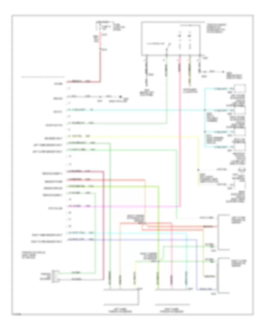
NAVIGATION Parking Assistant Wiring Diagram for Ford Windstar 2000 List of elements for Parking Assistant Wiring Diagram for Ford Windstar 2000: 57 (right b pillar) (right corner of parking aid sensor) C216 C219 C231 C257 C340 C352 C355 C402 C440 C441 C443 C444 Data link connector Fuse 10 10a Fuse junction panel G200 (behind left kick panel) G205 (behind right side of dash) G305 Ground Hot in run Instrument illumination Iso 9141 Left inner parking aid sensor Left inner sensor input Left outer parking aid sensor Left outer sensor input Left power sliding door module (left rear quarter panel) On/off switch Parking aid module (right rear of vehicle) Parking aid sounder Power Rear electronic module (right rear quarter panel) Rear sounder (+) Rear sounder (-) Restraint control module (lower left side of dash) Reverse input Right inner parking aid sensor Right inner sensor input Right outer parking aid sensor Right outer sensor input Right power sliding door module (right rear quarter panel) Right reversing lamp S202 S210 (main harness, near air bag module) S220 S309 (b/o in body harness, near inertia switch) S318 S320 (b/o in main body harness) S401 S403 S404 Sensor ground Sensor power Status led Traction assist/ parking aid disable switch (in glove box)
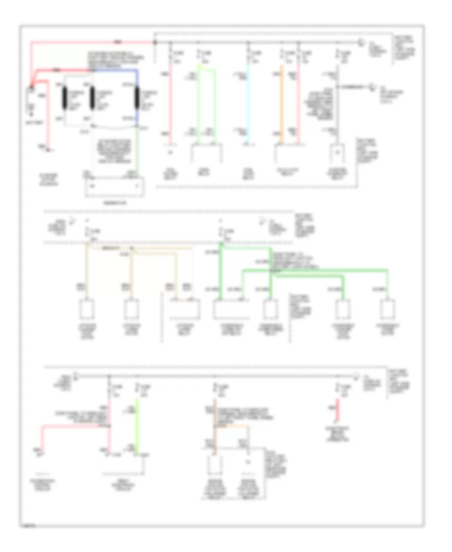
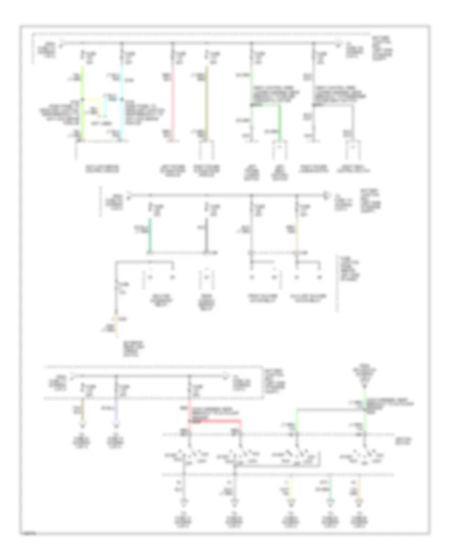
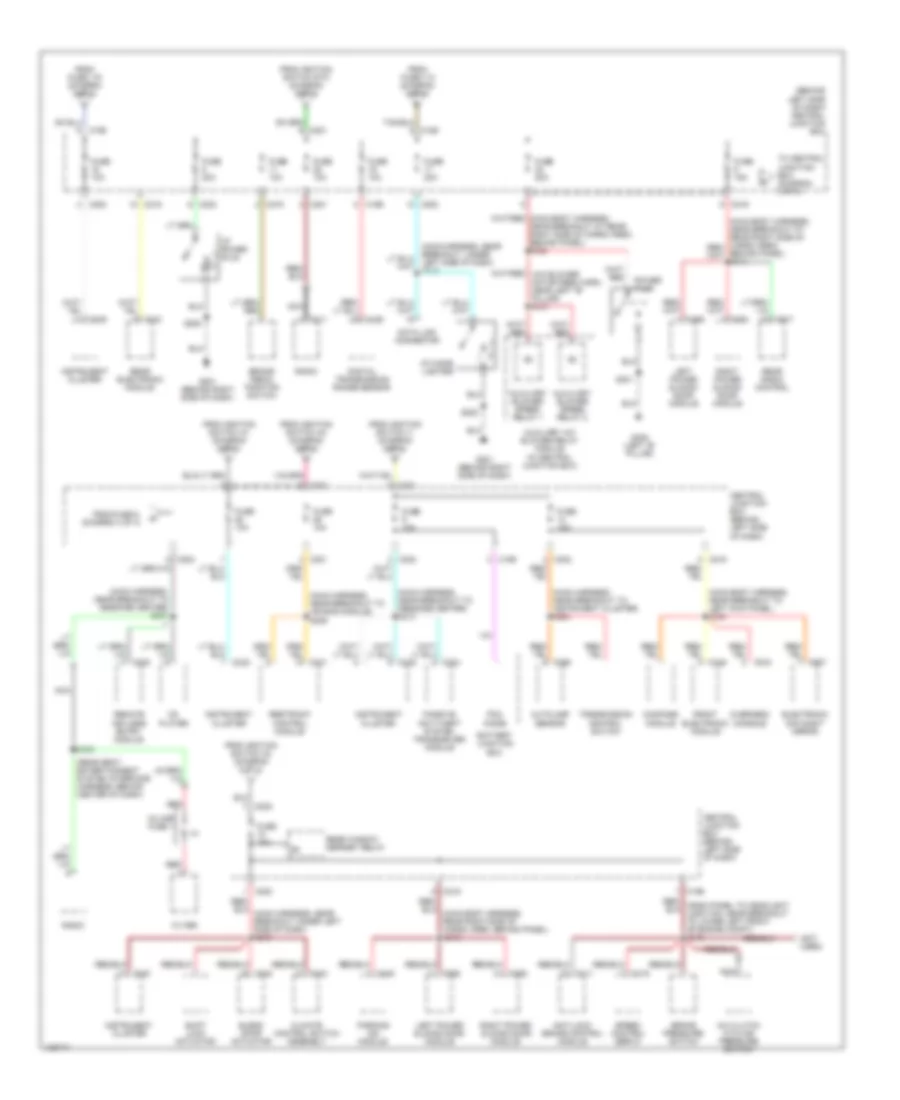
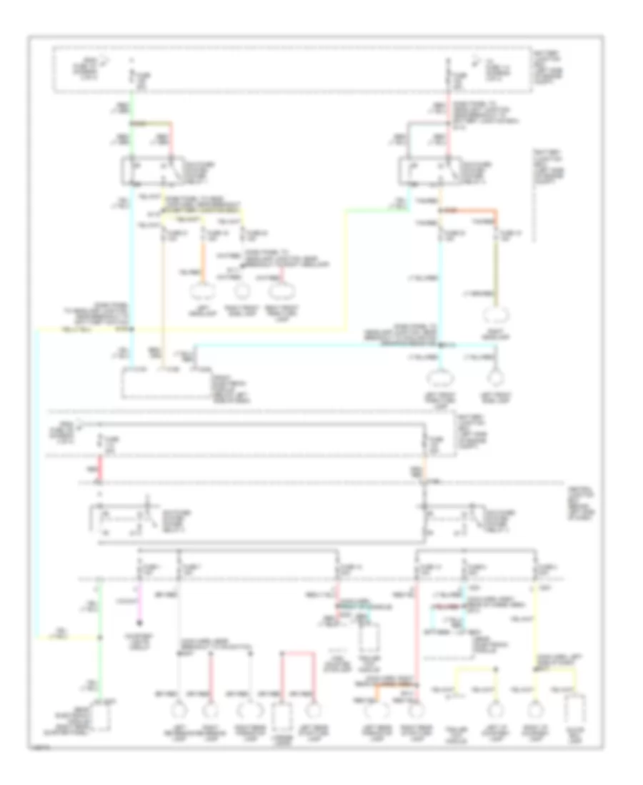
POWER DISTRIBUTION Power Distribution Wiring Diagram (1 of 4) for Ford Windstar 2000 List of elements for Power Distribution Wiring Diagram (1 of 4) for Ford Windstar 2000: 46 (dash panel to headlamp harness, near breakout to left front wheel speed sensor) s123 (dash panel to headlight junction, left rear of engine compt) s130 (dash panel to headlight junction, near breakout to battery junction box) s127 (starter motor relay & battery ground harness, near breakout for mass airflow sensor) (starter motor relay & battery ground harness, near breakout for mass airflow sensor) s142 2 of 4) A/c clutch relay Battery Battery junction box (left side of engine compt) C190 C348 Dual auxiliary relay box (at left rear side of engine compt) Electronic brake switch connector Engine cooling fan motor high speed relay Engine cooling fan motor low speed relay From fuse 105 (diagram 1 of 4) From fuse 6 (diagram 1 of 4) Front electronic module Fuel pump relay Fuse 10a Fuse 15a Fuse 25a Fuse 30a Fuse 50a Generator Horn relay Liftgate washer pump motor Liftgate wiper motor Liftgate wiper relay Pcm power relay Powertrain control module Red S124 (dash panel to headlamp harness, near breakout to left front wheel speed sensor) S126 S141 S143 Starter interrupt relay Starter motor/ solenoid To fuse 102 (diagram 2 0f 4) To fuse 2 (diagram 1 of 4) To fuse 7 (diagram 1 of 4) To splice s226 (diagram Windshield washer pump motor Windshield wiper motor Windshield wiper on/ off relay Windshield wiper speed relay Power Distribution Wiring Diagram (2 of 4) for Ford Windstar 2000 List of elements for Power Distribution Wiring Diagram (2 of 4) for Ford Windstar 2000: 53 (not used) (seat control feed jumper harness, near breakout to driver horizontal motor) s340 (seat control feed jumper harness, near breakout to passenger power seat switch) s341 Acc Anti-lock brake control module Auxiliary blower motor relay Battery junction box (left side of engine compt) C195 C196 C220 Delayed accessory relay Exterior rear view mirror switch From fuse 104 (diagram 2 of 4) From fuse 112 (diagram 1 of 4) From fuse 117 (diagram 2 of 4) From splice s124 (diagram 1 of 4) Front blower motor relay Fuse 10a Fuse 20a Fuse 30a Fuse 40a Fuse 50a Fuse junction panel (behind left side of dash) Ignition switch Left power lumbar switch Left power sliding door module Left seat control switch Lock Lock off Nca Off Rear window defrost relay Red (main harness, near breakout to autolamp sensor) s225 Red b1 Red b3 Right power lumbar switch Right power sliding door module Right seat control switch Run S128 (dash panel to headlamp junction, near breakout to anti-lock brake module) S129 (dash panel to headlamp junction, near breakout to anti-lock brake module) Sta Start To fuse 10 (diagram 3 of 4) To fuse 106 (diagram 2 of 4) To fuse 109 (diagram 4 of 4) To fuse 115 (diagram 2 of 4) To fuse 16 (diagram 3 of 4) To fuse 23 (diagram 3 of 4) To fuse 25 (diagram 3 of 4) To fuse 26 (diagram 3 of 4) To fuse 28 (diagram 3 of 4) To fuse 9 (diagram 3 of 4) Power Distribution Wiring Diagram (3 of 4) for Ford Windstar 2000 List of elements for Power Distribution Wiring Diagram (3 of 4) for Ford Windstar 2000: 90 (behind left side of dash) central junction box (main body harness, near breakout to left kick panel) s330 (main harness, near breakout to air bag module) s209 (main harness, near breakout to instrument cluster) s224 (main harness, near breakout to message center) s207 (main harness, near breakout to message center) s216 (not used) (rear seat entertainment system interface harness, behind center of dash) A/c clutch cycling pressure switch Anti-lock brake control module Autolamp sensor Auxiliary a/c blower relay module (in central junction box) Auxiliary blower speed relay 1 Auxiliary blower speed relay 2 Battery junction box Blend door actuator Brake pedal position switch Brake pressure switch C116 C126 C195 C196 C200 C201 C202 C211 C219 C231 C239 C240 C244 C260 C343 C346 C352 C355 C445 C907 C915 C917 Cd player Central junction box (behind left side of dash) Climate control switch assembly Compass module Data link connector Digital transmission range sensor Electronic day/night mirror Filter From fuse 115 (diagram 2 of 4) From fuse 119 (diagram 2 of 4) From fuse 6, (diagram 3 of 4) From ignition switch a1 (diagram 2 of 4) From ignition switch a3 (diagram 2 of 4) From ignition switch a4 (diagram 2 of 4) From ignition switch i1 (diagram 2 of 4) From ignition switch sta (diagram 2 of 4) Front electronic module Fuse 10a Fuse 15a Fuse 20a G201 (behind right side of dash) G308 (left "b" pillar) I/p cigar lighter I/p power plug In-line fuse 1 Instrument cluster Left power sliding door module Left side of dash) s218 Nca Overhead console Parking aid module Passive anti-theft system transceiver module Pcm diode Power plug Radio Rear electronic module Rear radio control Rear window defrost relay Red Remote keyless entry module Restraint control module Right power sliding door module S202 S208 S301 S350 Shift lock actuator Speed control servo To central junction box (diagram 3 of 4) Transmission control switch Power Distribution Wiring Diagram (4 of 4) for Ford Windstar 2000 List of elements for Power Distribution Wiring Diagram (4 of 4) for Ford Windstar 2000: 68 (dash panel to headlamp junction, near breakout to anti-theft switch) (dash panel to headlamp junction, near breakout to cooling fan dropping resistor) (dash panel to headlight junction, near breakout to battery junction box) s118 (main harn, front of console) (main harn, left side of dash) s217 (main harn, near breakout to ifs switch) s307 (main harn, right rear of cargo area) Battery junction box (left side of engine compt) C191 C192 C196 C201 C221 C342 C343 C344 C346 Central junction box (behind left side of dash) Courtesy lights circuit From p fuse 121 (diagram 2 of 4) From q fuse 108 (diagram 4 of 4) Front electronic module (below left side of dash) Fuse 1 10a Fuse 12 20a Fuse 13 15a Fuse 15 15a Fuse 16 15a Fuse 2 20a Fuse 21 10a Fuse 22 15a Fuse 23 15a Fuse 40a Fuse 7 15a Fuse 8 20a Glove box lamp High mounted stoplamp Left front park/turn lamp Left front side lamp Left headlamp Left i/p courtesy lamp Left rear park/stop lamp Left rear stop/turn lamp Left reversing lamp License lamps Rear electronic module Rear electronic module (right rear quarter panel) Red Right front park/turn lamp Right front side lamp Right headlamp Right i/p courtesy lamp Right rear park/stop lamp Right rear stop/turn lamp Right reversing lamp S111 S114 S119 S120 S121 S135 S314 Switched system power relay 1 Switched system power relay 2 Switched system power relay 3 Switched system power relay 4 Tan/red To fuse 114 (diagram 4 0f 4) Trailer tow module
POWER DOOR LOCKS Power Door Lock Wiring Diagram for Ford Windstar 2000 List of elements for Power Door Lock Wiring Diagram for Ford Windstar 2000: 39 (dash panel to headlamp harn, near engine cooling fan breakout) s138 (left kick panel) g200 (main body harn, near front electronics module (fem) breakout) (main body harn, right rear of vehicle) (main body harn, right rear of vehicle) s311 (main harn, near message center breakout) s215 C190 C202 C341 C342 C344 C346 C347 Central junction box (behind left side of dash) Front electronic module (below left side of dash) Fuse 6 15a G200 (left kick panel) Hot at all times Left door lock actuator Left door lock switch Left sliding door lock actuator Liftgate door lock actuator Lock Rear electronic module (at right rear quarter panel) Red Remote keyless entry module (behind right side of dash) Right door lock actuator Right door lock switch Right sliding door lock actuator S137 (dash panel to headlamp harn, near engine coling fan breakout) S214 (main harn, near message center breakout) S220 S312 S334 S335 (main body harn, near front electronics module (fem) breakout) S500 S600 Sliding door contact assemblies Unlk
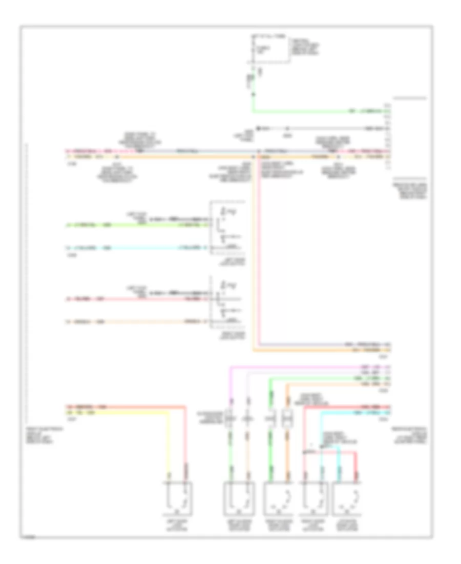
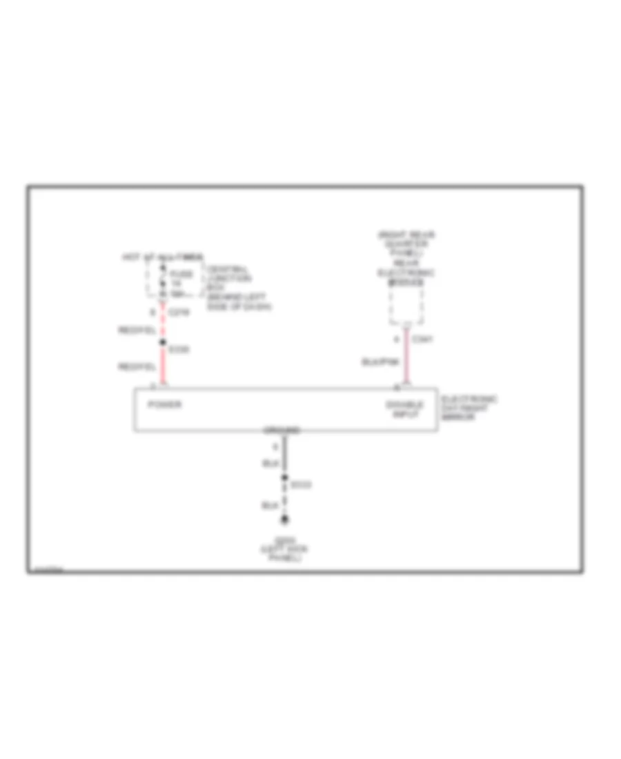
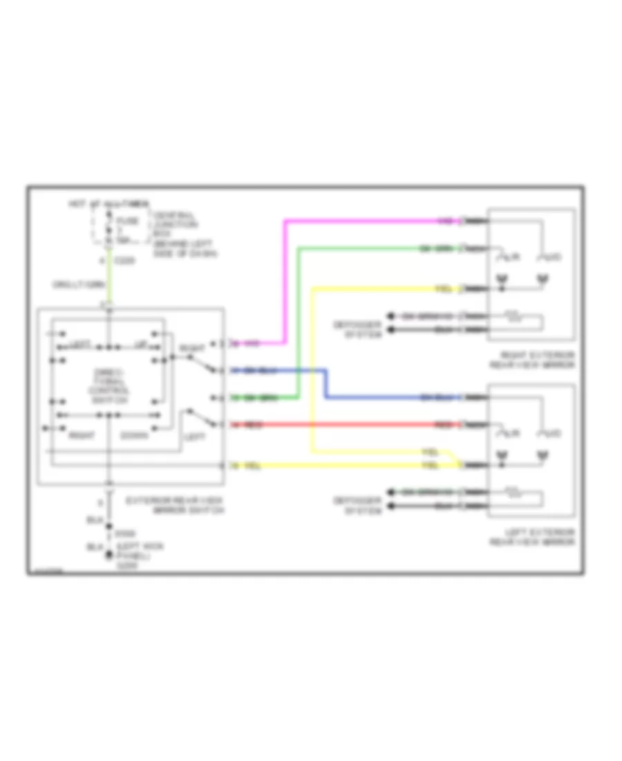
POWER MIRRORS Electronic Day/Night Mirror Wiring Diagram for Ford Windstar 2000 List of elements for Electronic Day/Night Mirror Wiring Diagram for Ford Windstar 2000: 14 (right rear quarter panel) rear electronic module C219 C341 Central junction box (behind left side of dash) Disable Electronic day/night mirror Fuse 10a G200 (left kick panel) Ground Hot at all times Input Power S330 S333 Power Mirrors Wiring Diagram for Ford Windstar 2000 List of elements for Power Mirrors Wiring Diagram for Ford Windstar 2000: 18 (left kick panel) g200 C220 Central junction box (behind left side of dash) Defogger system Direc- tional control switch Down Exterior rear view mirror switch Fuse 10a Hot at all times L/r Left Left exterior rear view mirror Nca Red Right Right exterior rear view mirror S500 U/d
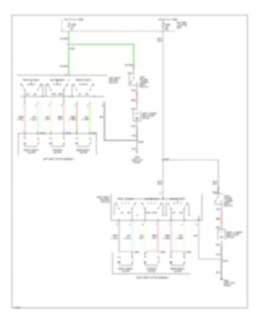
POWER SEATS Power Seat Wiring Diagrams for Ford Windstar 2000 List of elements for Power Seat Wiring Diagrams for Ford Windstar 2000: 32 Battery junction box C317 C318 C319 C358 C359 C360 Entire seat Front height motor Front of seat Fuse Fuse 40a Fwd/rwd motor G200 (left kick panel) Hot at all times Left lumbar seat pump motor Left power lumbar seat switch Left seat control switch Left seat motor assembly Nca Rear height motor Rear of seat Red Right lumbar seat pump motor Right power lumbar seat switch Right seat control switch Right seat motor assembly Rwd fwd S339 S340 S341 S342
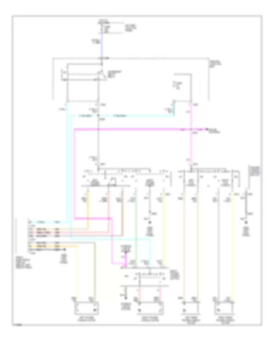
POWER WINDOWS Power Window Wiring Diagram for Ford Windstar 2000 List of elements for Power Window Wiring Diagram for Ford Windstar 2000: 33 Accessory delay relay Battery junction panel C191 C196 C220 C221 C347 C348 C501 C514 Central junction box Front electronic module (below left side of dash) Fuse 10a Fuse 30a G200 (left kick panel) Hot at all times Interior lights system Left flip window Left power window Left power window motor Left rear power window motor M m Master window control switch Otd Right flip window Right power window Right power window motor Right power window switch Right rear power window motor S326 S327 S500 Sound systems
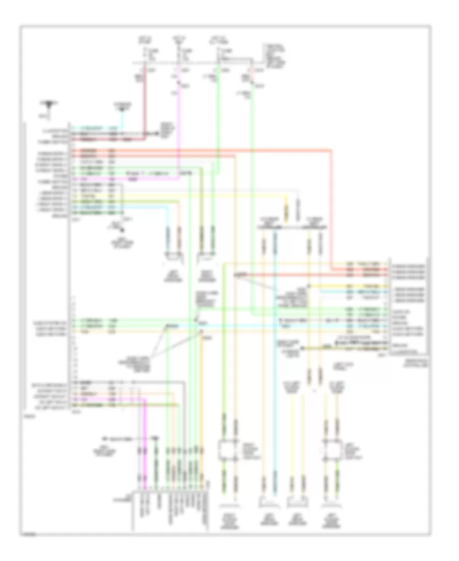
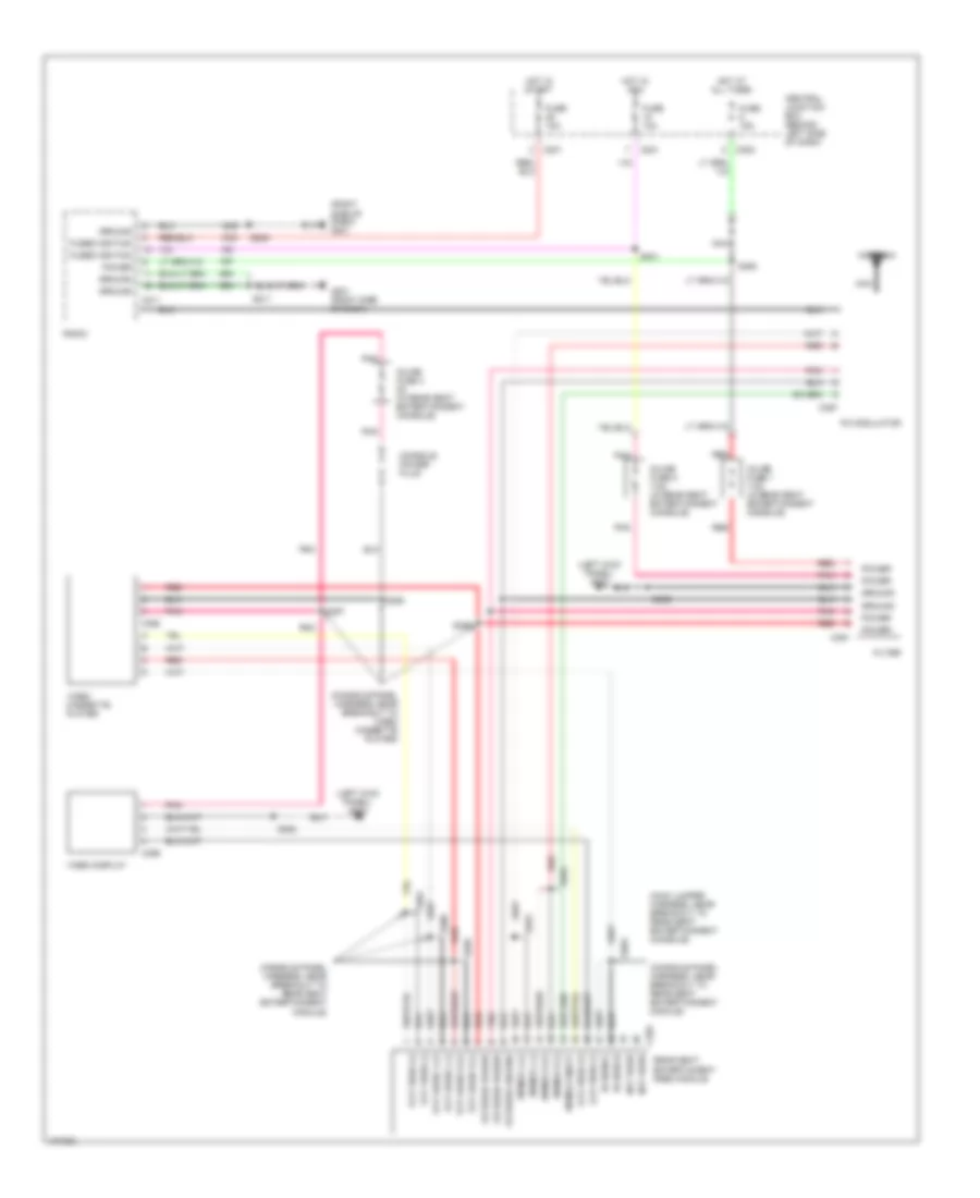
RADIO Radio Wiring Diagram for Ford Windstar 2000 List of elements for Radio Wiring Diagram for Ford Windstar 2000: 80 (dash harn, near breakout to message center) (dash harn, near breakout to radio) (left kick panel) (right side of dash) (right side of dash) g201 (w/ sliding door) s337 Antenna Audio network Audio on Audio system on Bare C201 C202 C211 C213 C219 C221 C237 C917 Cd changer Cd left sig in Cd left sig out Cd player shield Cd right sig in Cd right sig out Central junction box (behind left side of dash) Fuse 10a Fuse 15a Fused ignition G200 G201 G201 (right side of dash) Ground Hot at all times Hot in acc Hot in start Illumination Interior lights L front spkr (+) L front spkr (-) L rear speaker L rear spkr (+) L rear spkr (-) Left front speaker Left rear speaker Left sig (+) Left sig (-) Left sliding door contact Left sliding door speaker Nca Power R front spkr (+) R front spkr (-) R rear speaker R rear spkr (+) R rear spkr (-) Radio Rear radio controller Right front speaker Right sig (+) Right sig (-) Right sliding door contact Right sliding door speaker S204 S205 S206 S207 S208 S211 S231 S315 S328 (main harn, near breakout to left kick panel ground) S329 S350 Shield Tan W/ left sliding door W/ rear seat controller W/o left sliding door W/o rear seat controller Video System Wiring Diagram for Ford Windstar 2000 List of elements for Video System Wiring Diagram for Ford Windstar 2000: 70 (console panel harness, near breakout to rear seat entertainment module) (console panel harness, near breakout to video cassette player) (left kick panel) g200 (main jumper harness, near breakout to rear seat entertainment console) (right side of dash) g201 Antenna C201 C202 C211 C221 C391 C392 C393 C395 C397 Central junction box (behind left side of dash) Console power plug Filter Filtered ground Filtered power Fm mod l (+) Fm mod l (-) Fm mod on/off Fm mod r (+) Fm mod r (-) Fm modulator Fuse 10a Fuse 15a Fused ignition G201 (right side of dash) Ground Hot at all times Hot in acc Hot in start Inline fuse 1 7.5a (in rear seat entertainment console) Inline fuse 2 7.5a (in rear seat entertainment console) Inline fuse 3 5a (in rear seat entertainment console) Ir shield Ir signal Lcd video (+) Lcd video (-) Nca Not used Pnk Power Radio Rear seat entertaiment (rse) module Red S208 S211 S231 S350 S352 S353 S354 S356 S357 S358 S359 S360 S361 S363 Vcp audio l (+) Vcp audio l (-) Vcp audio r (+) Vcp audio r (-) Vcp video (+) Vcp video (-) Video cassette player Video display
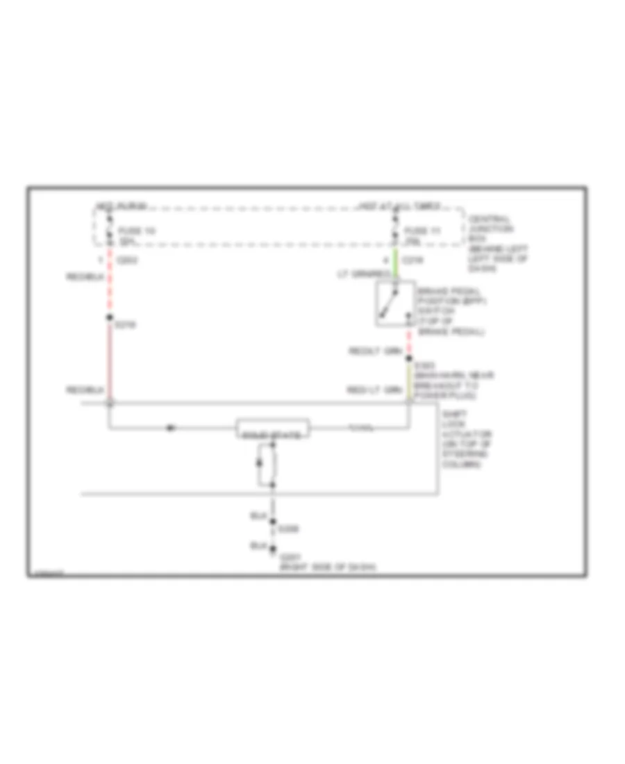
SHIFT INTERLOCKS Shift Interlock Wiring Diagram for Ford Windstar 2000 List of elements for Shift Interlock Wiring Diagram for Ford Windstar 2000: 15 Brake pedal position (bpp) switch (top of Brake pedal) C202 C219 Central junction box (behind left left side of dash) Fuse 10 10a Fuse 11 10a G201 (right side of dash) Hot at all times Hot in run S208 S219 S303 (main harn, near breakout to power plug) Shift lock actuator (on top of steering column) Solid state
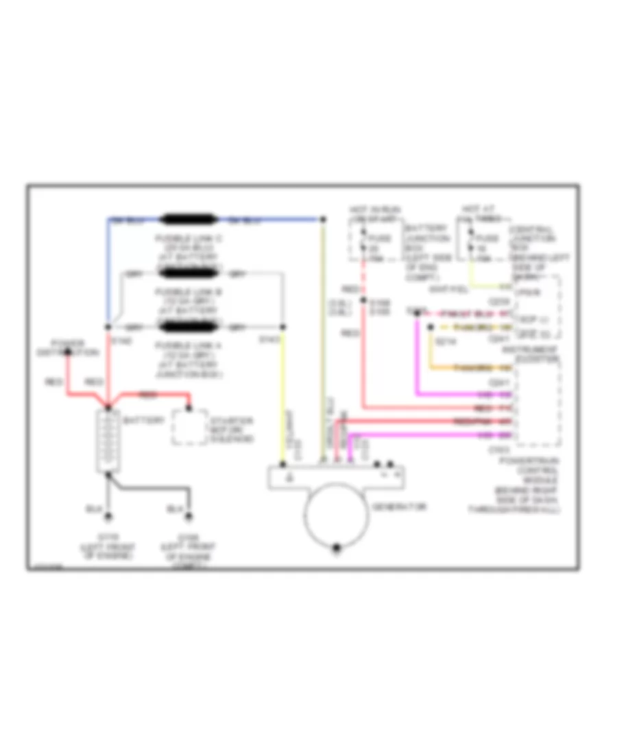
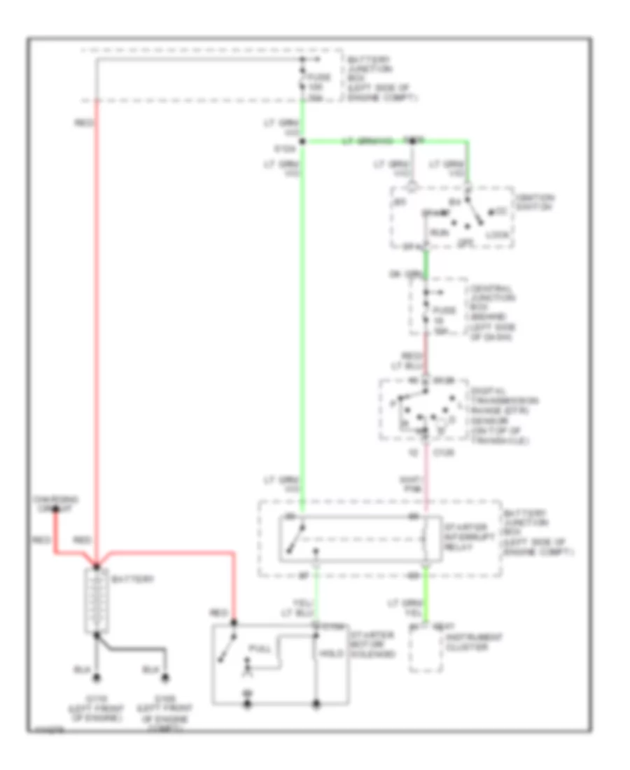
STARTING/CHARGING Charging Wiring Diagram for Ford Windstar 2000 List of elements for Charging Wiring Diagram for Ford Windstar 2000: 30 (3.0l) (3.8l) Battery Battery junction box (left side of eng compt) C103 C123 C133 C239 C241 Central junction box (behind left side of dash) Fuse 10a Fuse 15a G106 (left front of engine compt) G110 (left front of engine) Generator Hot at all times Hot in run or start Instrument cluster Power distribution Powertrain control module (behind right side of dash, through firewall) Pwr Red Red/pnk S108 s105 S142 S143 S214 S215 Scp (+) Scp (-) Starter motor/ solenoid Starting Wiring Diagram for Ford Windstar 2000 List of elements for Starting Wiring Diagram for Ford Windstar 2000: 27 Acc Battery Battery junction box (left side of engine compt) C126 C134 C241 Central junction box (behind left side of dash) Charging circuit Digital transmission range (dtr) sensor (on top of transaxle) Fuse 10a Fuse 30a G106 (left front of engine compt) G110 (left front of engine) Hold Ignition switch Instrument cluster Lock Off Pull Red Run S124 S226 Sta Start Starter interrupt relay Starter motor/ solenoid
SUPPLEMENTAL RESTRAINTS Supplemental Restraint Wiring Diagram for Ford Windstar 2000 List of elements for Supplemental Restraint Wiring Diagram for Ford Windstar 2000: 48 (main harness, near breakout to air bag module) s209 (main harness, near breakout to air bag module) s210 (main harness, near breakout to message center) s216 (partial) below dash, on right of steering column) Air bag indicator Air bag indicator system Air bag sliding contact Air bag tone c240 Air bag warning tone (out) C201 C202 C231 C232 C240 C241 Central junction box (behind left side of dash) Computer data lines system Data link conn (dlc) Data link connector (dlc) Driver air bag Driver air bag feed Driver air bag return Driver side air bag Driver side air bag feed Driver side air bag return Driver side impact air bag sensor (under driver's seat) Driver side sensor feed Driver side sensor return Fuse 26 10a Fuse 9 10a Fused ignition G100 (left front of engine compartment) Ground Hot in run Hot in run or start Ignition Instrument cluster Nca Pass air bag feed Pass air bag return Pass side air bag feed Pass side air bag return Pass side sensor feed Pass side sensor return Passenger air bag Passenger side air bag Passenger's side impact air bag sensor (under passenger's seat) Restraint control module (rcm) (behind left side of dash)
TRANSMISSION A/T Wiring Diagram for Ford Windstar 2000 List of elements for A/T Wiring Diagram for Ford Windstar 2000: 76 (dash to hdlmp harn, near breakout to engine cooling fan motor) (engine harn, left rear of engine compt) (engine harn, left side of engine compt) (engine harn, near breakout oss sensor) (engine harn, near breakout to dtr sensor) (engine harn, near breakout to pcm) A/c clutch relay, canister vent solenoid Ax4s transmission Batt Battery junction box (left side of engine compt) C103 C195 Computer data lines system Cooling fan motors, fuel pump relay Data link connector (behind dash, right of steering column) Digital transmission range sensor (on top of transaxle) Dlc Dlc(+) Dlc(-) Dtr sens Ect Electronic pressure control solenoid Engine controls Engine coolant temperature (cht) sensor (on rear of engine) Epc sol Evap valve, egr valve, ho2 sensor, imrc monitor Front electronic module Fuse 10a Fuse 15a Fuse 30a Fuse junction panel (behind left side of dash) G106 (left front G130 (on transaxle stud) Ground Hot at all times Hot in run or start Ignition coil, fuel injectors, maf sensor, iac valve Of engine compt) Oss Output shaft speed (oss) sensor (left side of eng compt) Pcm power diode Pcm power relay Power Powertrain control module (pcm) (behind right side of dash, through firewall) R p Red Return S100 S101 S102 S103 S105 S106 S107 S110 3.0l S115 S125 S130 S133 S137 S138 Shift solenoid 1 Shift solenoid 2 Shift solenoid 3 Ss1 Ss2 Ss3 Tcc Tft Throttle position (tp) sensor (top of engine) Torque converter clutch solenoid Tp sens Transmission fluid temperature sensor Tss Turbine shaft speed (tss) sensor (on top of transaxle) Vref
TRUNK, TAILGATE, FUEL DOOR Power Sliding Door for Ford Windstar 2000 List of elements for Power Sliding Door for Ford Windstar 2000: 87 (at left rear quarter panel) left power sliding door module (behind left rear taillight) g404 (left kick panel) (main harn, near breakout to g305) (main harn, right rear of cargo area) (rear door harn, near breakout to door lock actuator) (right of steering column) 6 mph Battery junction box C219 C341 C342 C351 C352 C354 C355 C943 C947 C948 C950 C950 c950 C951 C952 C953 C954 C955 Data link Data link connector Fuel door interlock switch Fuel dr Fuse 10a Fuse 15a Fuse 50a Fuse junction panel G200 Ground Hot at all times Ignition Left o/c sen Left power sliding door clutch Left power sliding door detent switch Left power sliding door latch release actuator Left power sliding door lock actuator Left power sliding door motor Left power sliding door position sensor Left power sliding door switch Lt detent Lt dr sw Lt o/c rem Lt on/off Lt park Lt unlatch Nca Overhead console Power Rear electronic module (at right rear quarter panel) Red Return Right power sliding door clutch Right power sliding door detent switch Right power sliding door latch release actuator Right power sliding door lock actuator Right power sliding door module (at right rear quarter panel) Right power sliding door motor Right power sliding door position sensor Right power sliding door switch Rt detent Rt dr sw Rt o/c rem Rt o/c sen Rt on/off Rt park Rt unlatch S302 S315 S317 S318 S319 S320 S321 S323 S337 S700 S800 Sliding door contact Sliding door contacts Tan/red
WARNING SYSTEMS Warning System Wiring Diagrams for Ford Windstar 2000 List of elements for Warning System Wiring Diagrams for Ford Windstar 2000: 60 (body harn, near breakout to front electronic module) (dash panel to headlight junction harness, near breakout to engine cooling high/low fan motor) (main harn, near breakout to message center) Battery junction box Brake fld lev sw Brake fluid warning switch (left rear of engine compt) C190 C241 C341 C342 C343 C346 C347 C348 Computer data lines system Driver belt sw Driver dr ajar sw Eng oil press sw Engine oil pressure switch (top rear of engine) Front electronic module (below left side of dash) Fuse 10a Fuse 15a G106 (lower left front of engine compt) G200 (left kick panel) G308 (left "b" pillar) Hot at all times Instrument cluster Left door ajar switch Left liftgate ajar switch Left sliding door ajar switch Liftgate ajar sw Lr ajar sw Nca Park brake sw Parking brake switch (at base of park brake handle) Pass door sw Rear electronic module (at right rear quarter panel) Red Right door ajar switch Right liftgate ajar switch Right sliding door ajar switch Rr ajar sw S132 S137 S138 S214 S215 S218 S300 S334 S335 S500 S600 Safety belt buckle switch (in driver's safety belt buckle) Scp + Scp - Scpb + Scpb- Tan V batt
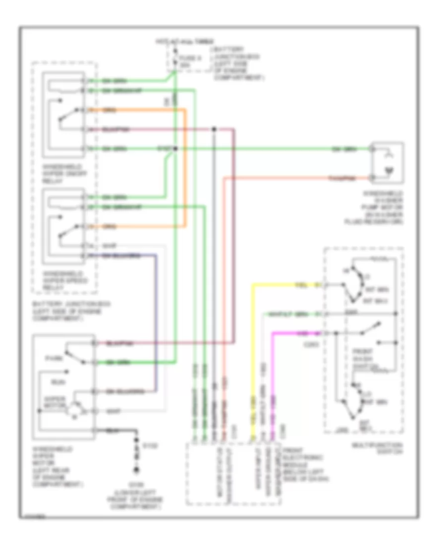
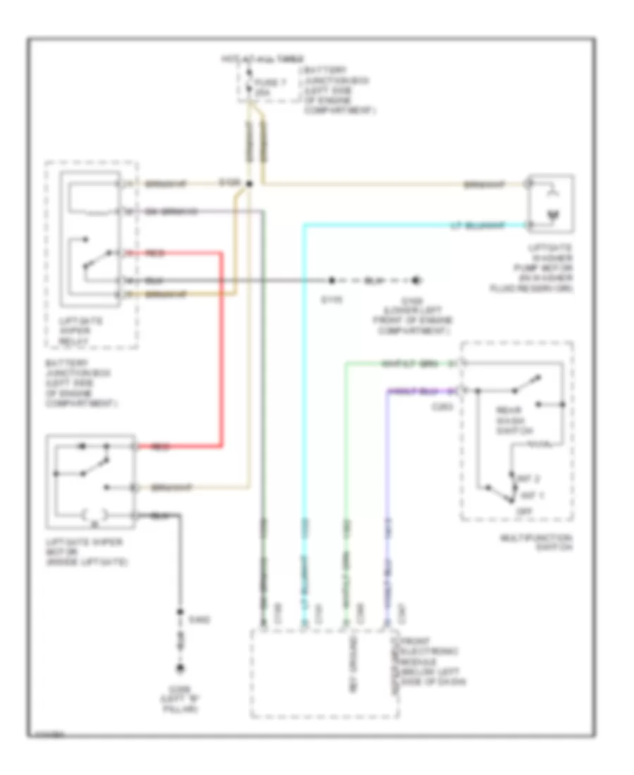
WIPER/WASHER Front Wiper/Washer Wiring Diagram for Ford Windstar 2000 List of elements for Front Wiper/Washer Wiring Diagram for Ford Windstar 2000: 27 Battery junction box (left side of engine compartment) C191 C263 C346 Front electronic module (below left side of dash) Fuse 6 30a G106 (lower left front of engine compartment) Hot at all times Int max Int min Motor status Multifunction switch Off Park Run S127 S132 Tan/pnk Washer input Washer output Windshield washer pump motor (in washer fluid reservoir) Windshield wiper motor (left rear of engine compartment) Windshield wiper on/off relay Windshield wiper speed relay Wiper ground Wiper input Wiper motor Rear Wiper/Washer Wiring Diagram for Ford Windstar 2000 List of elements for Rear Wiper/Washer Wiring Diagram for Ford Windstar 2000: 23 Battery junction box (left side of engine compartment) C190 C191 C263 C346 C347 Fuse 7 25a G100 (lower left front of engine compartment) G308 (left "b" pillar) Hot at all times Int 1 Int 2 Liftgate washer pump motor (in washer fluid reservoir) Liftgate wiper motor (inside liftgate) Liftgate wiper relay Multifunction switch Off Red Ref ground S115 S126 S402 Wiper input front electronic module (below left side of dash)