Diagram sections — 10 (15 total)
COOLING FAN DEFOGGERS HORN POWER ANTENNA POWER DOOR LOCKS POWER MIRRORS POWER WINDOWS RADIO STARTING/CHARGING WIPER/WASHER
COOLING FAN
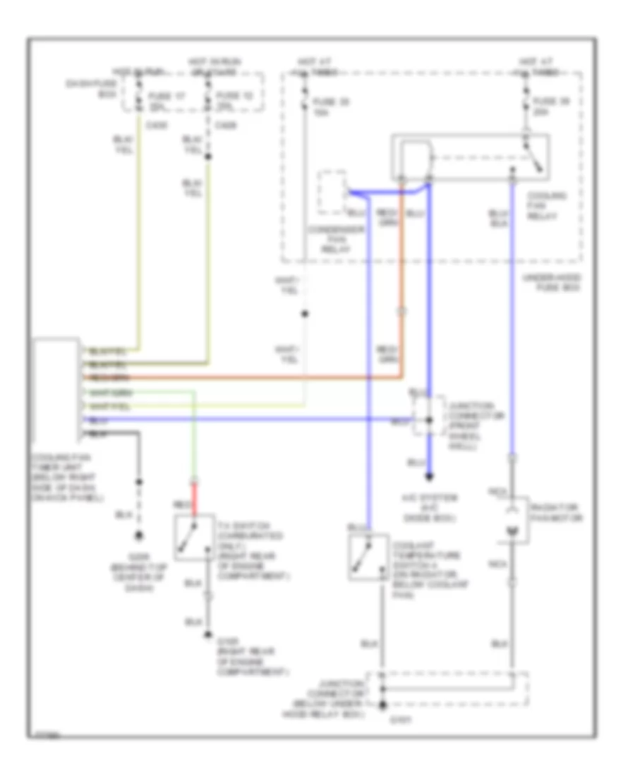
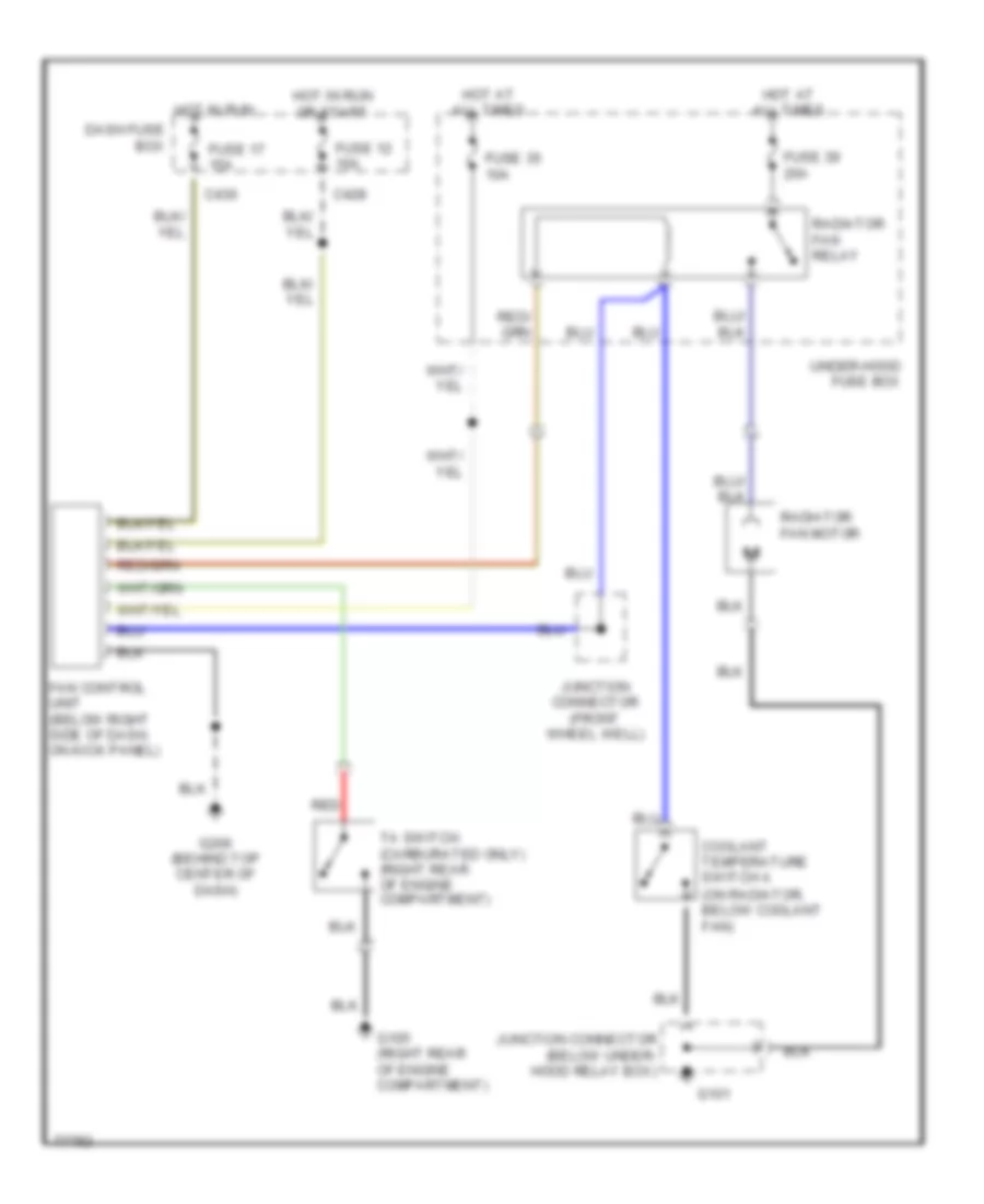
2.0L 2.0L, Cooling Fan Wiring Diagram, with A/C for Honda Prelude 2.0 Si 1991 List of elements for 2.0L, Cooling Fan Wiring Diagram, with A/C for Honda Prelude 2.0 Si 1991: 25 A/c system (a/c diode box) C428 C430 Condenser fan relay Coolant temperature switch a (on radiator, below coolant fan) Cooling fan relay Cooling fan timer unit (below right side of dash, on kick panel) Dash fuse box Fuse 12 10a Fuse 17 15a Fuse 35 10a Fuse 39 20a G101 G105 (right rear of engine compartment) G206 (behind top center of dash) Hot at all times Hot in run Hot in run or start Junction connector (below under- hood relay box) Junction connector (front wheel well) Nca Radiator fan motor Red Ta switch (carburated only) (right rear of engine compartment) Under-hood fuse box 2.0L, Cooling Fan Wiring Diagram, without A/C for Honda Prelude 2.0 Si 1991 List of elements for 2.0L, Cooling Fan Wiring Diagram, without A/C for Honda Prelude 2.0 Si 1991: 23 (on radiator, below coolant fan) C428 C430 Coolant temperature switch a Dash fuse box Fan control unit (below right side of dash, on kick panel) Fuse 12 10a Fuse 17 15a Fuse 35 10a Fuse 39 20a G101 G105 (right rear of engine compartment) G206 (behind top center of dash) Hot at all times Hot in run Hot in run or start Junction connector (below under- hood relay box) Junction connector (front wheel well) Radiator fan motor Radiator fan relay Red Ta switch (carburated only) (right rear of engine compartment) Under-hood fuse box
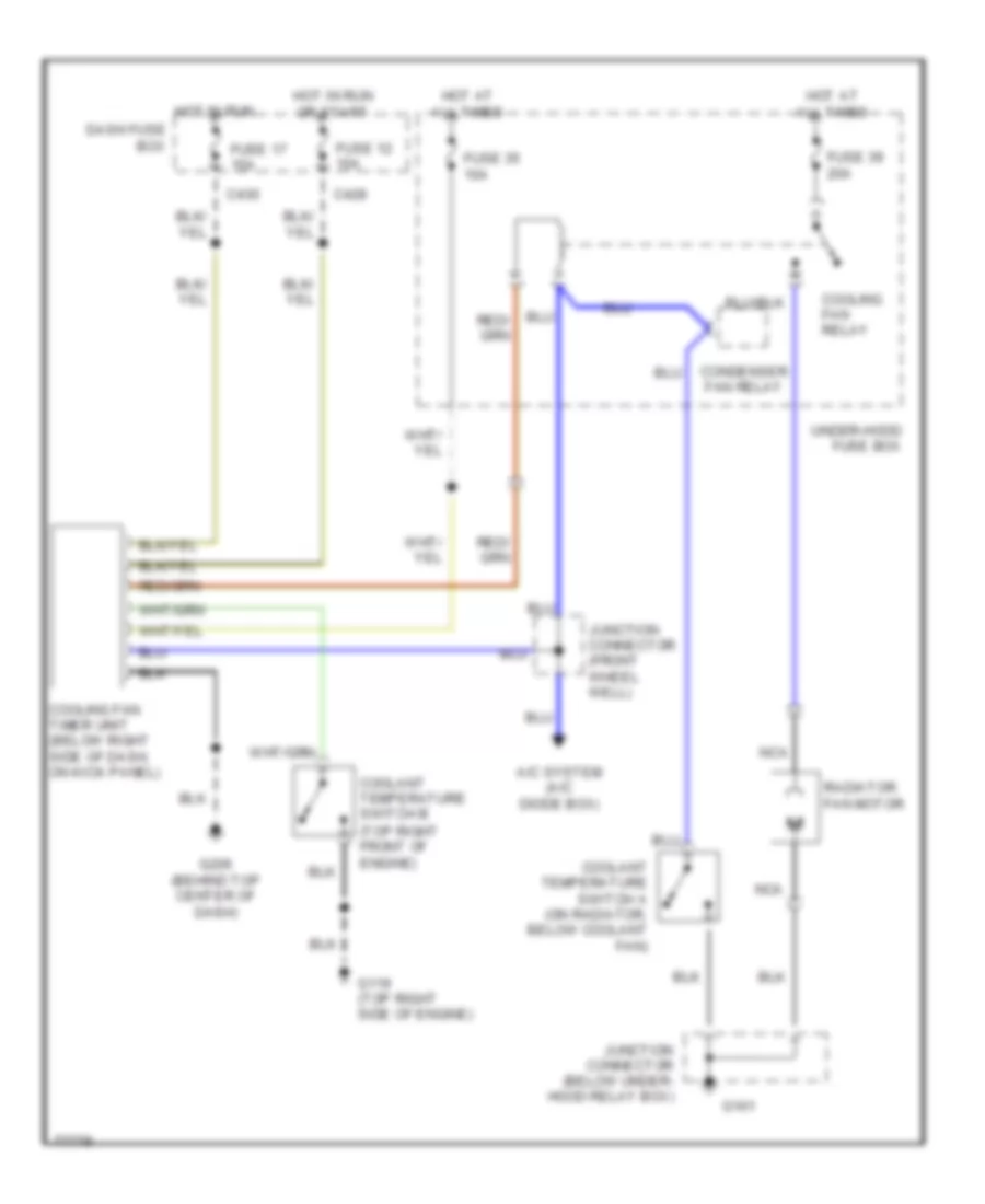
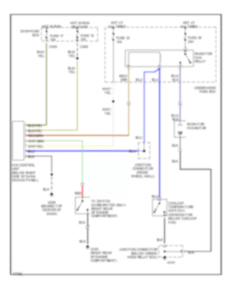
2.1L 2.1L, Cooling Fan Wiring Diagram, with A/C for Honda Prelude 2.0 Si 1991 List of elements for 2.1L, Cooling Fan Wiring Diagram, with A/C for Honda Prelude 2.0 Si 1991: 25 (top right front of engine) A/c system (a/c diode box) C428 C430 Condenser fan relay Coolant temperature switch a (on radiator, below coolant fan) Coolant temperature switch b Cooling fan relay Cooling fan timer unit (below right side of dash, on kick panel) Dash fuse box Fuse 12 10a Fuse 17 15a Fuse 35 10a Fuse 39 20a G101 G119 (top right side of engine) G206 (behind top center of dash) Hot at all times Hot in run Hot in run or start Junction connector (below under- hood relay box) Junction connector (front wheel well) Nca Radiator fan motor Under-hood fuse box 2.1L, Cooling Fan Wiring Diagram, without A/C for Honda Prelude 2.0 Si 1991 List of elements for 2.1L, Cooling Fan Wiring Diagram, without A/C for Honda Prelude 2.0 Si 1991: 23 (on radiator, below coolant fan) C428 C430 Coolant temperature switch a Dash fuse box Fan control unit (below right side of dash, on kick panel) Fuse 12 10a Fuse 17 15a Fuse 35 10a Fuse 39 20a G101 G105 (right rear of engine compartment) G206 (behind top center of dash) Hot at all times Hot in run Hot in run or start Junction connector (below under- hood relay box) Junction connector (front wheel well) Radiator fan motor Radiator fan relay Red Ta switch (carburated only) (right rear of engine compartment) Under-hood fuse box
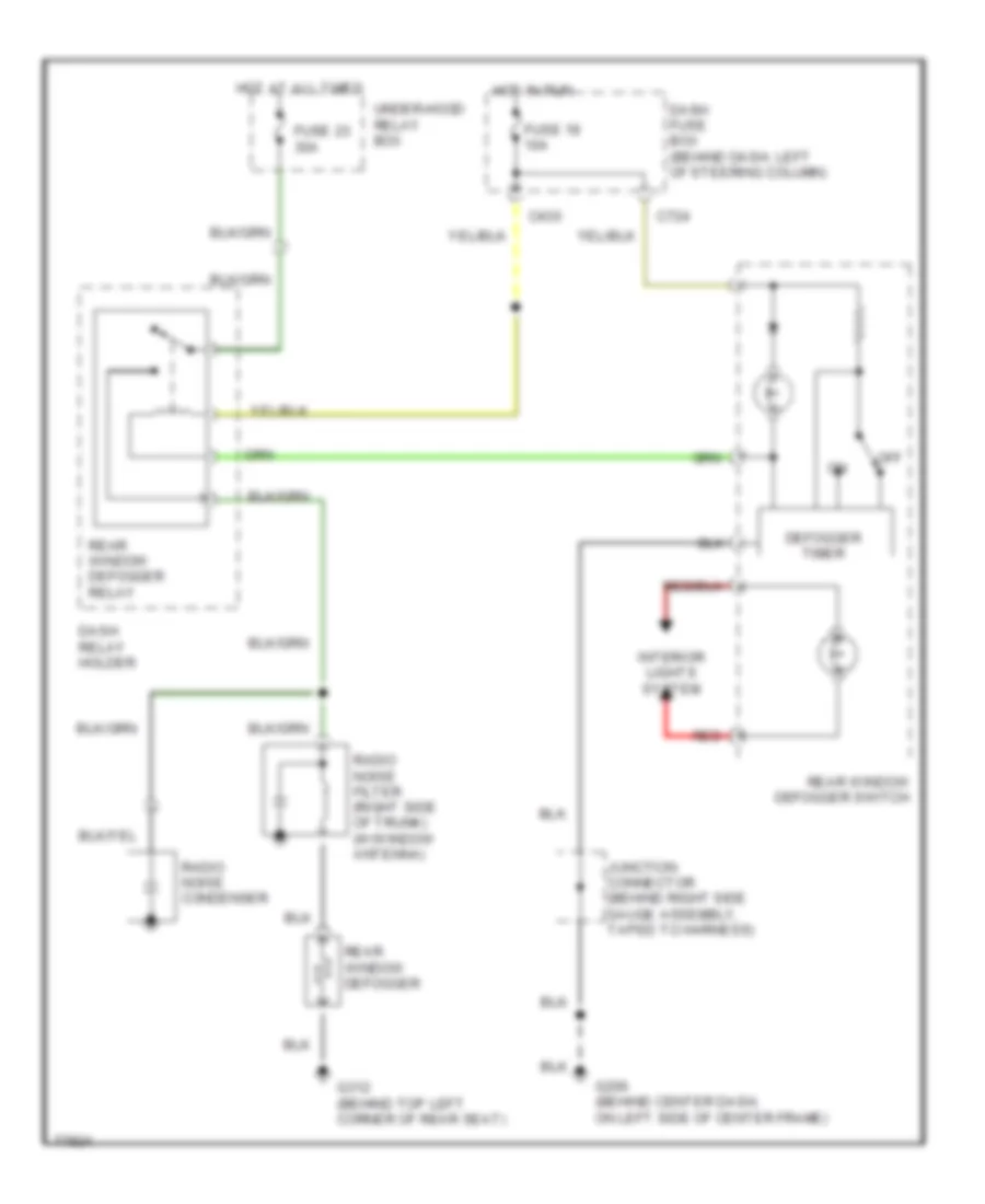
DEFOGGERS Defogger Wiring Diagram for Honda Prelude 2.0 Si 1991 List of elements for Defogger Wiring Diagram for Honda Prelude 2.0 Si 1991: 21 C430 C724 Dash fuse box (behind dash, left of steering column) Dash relay holder Defogger timer Fuse 18 10a Fuse 23 30a G206 (behind center dash, on left side of center frame) G312 (behind top left corner of rear seat) Hot at all times Hot in run Interior lights system Junction connector (behind right side gauge assembly, taped to harness) Off Radio noise condenser Radio noise filter (right side of trunk) (w/window antenna) Rear window defogger Rear window defogger relay Rear window defogger switch Red Under-hood relay box
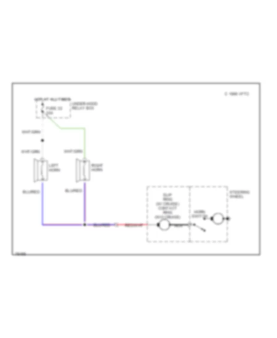
HORN Horn Wiring Diagram for Honda Prelude 2.0 Si 1991 List of elements for Horn Wiring Diagram for Honda Prelude 2.0 Si 1991: 10 C 1996 vftc Fuse 32 20a Horn switch Hot at all times Left horn Nca Right horn Slip ring (w/ cruise) contact ring (w/o cruise) Steering wheel Under-hood relay box
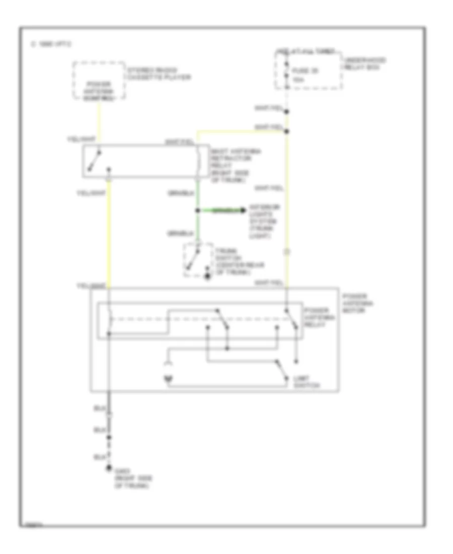
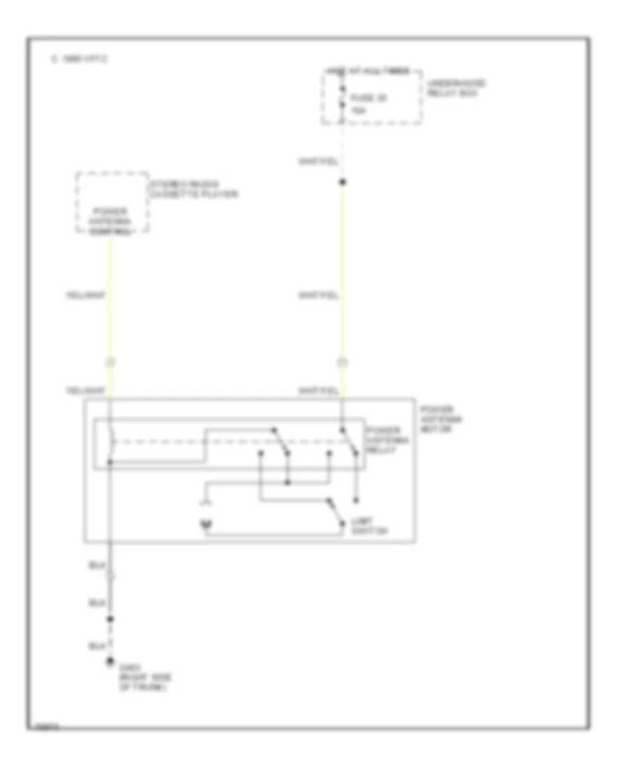
POWER ANTENNA Power Antenna Wiring Diagram, with Spoiler for Honda Prelude 2.0 Si 1991 List of elements for Power Antenna Wiring Diagram, with Spoiler for Honda Prelude 2.0 Si 1991: 14 10a 1995 vftc c Fuse 35 G403 (right side of trunk) Hot at all times Interior lights system (trunk light) Limit switch Mast antenna retractor relay (right side of trunk) Power antenna control Power antenna motor Power antenna relay Stereo radio/ cassette player Trunk switch (center rear of trunk) Under-hood relay box Power Antenna Wiring Diagram, without Spoiler for Honda Prelude 2.0 Si 1991 List of elements for Power Antenna Wiring Diagram, without Spoiler for Honda Prelude 2.0 Si 1991: 11 10a 1995 vftc c Fuse 35 G403 (right side of trunk) Hot at all times Limit switch Power antenna control Power antenna motor Power antenna relay Stereo radio/ cassette player Under-hood relay box
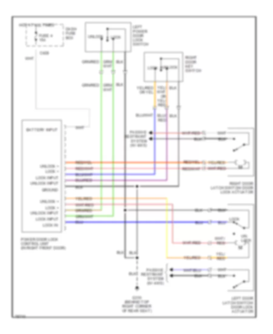
POWER DOOR LOCKS Power Door Lock Wiring Diagram for Honda Prelude 2.0 Si 1991 List of elements for Power Door Lock Wiring Diagram for Honda Prelude 2.0 Si 1991: 21 Battery input C428 Dash fuse box Fuse 4 15a G310 (behind top right corner of rear seat) Ground Hot at all times Left door latch switch/ door lock actuator Left power door lock switch Lock Lock + Lock in Lock input Passive restraint system (w/ 4ws) Power door lock control unit (in right front door) Right door key switch Right door latch switch/ door lock actuator Un- lock Unlock Unlock + Unlock input
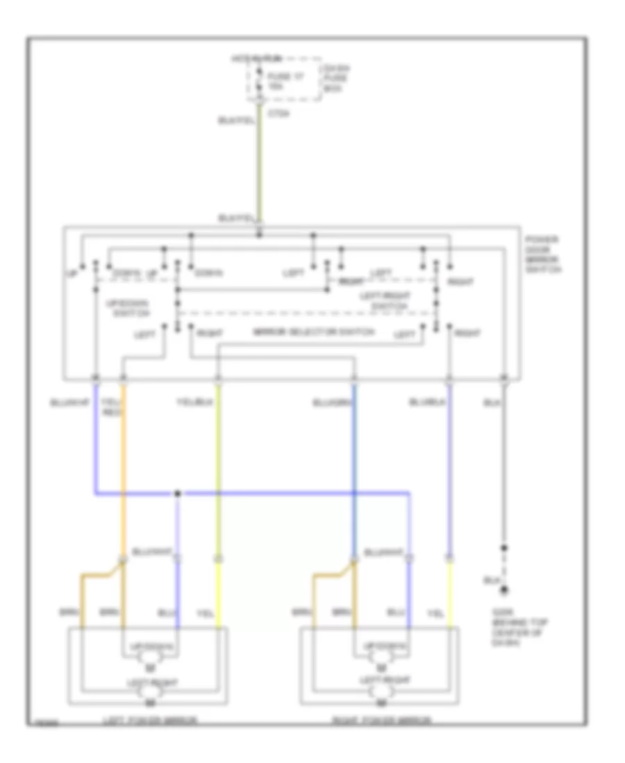
POWER MIRRORS Power Mirror Wiring Diagram for Honda Prelude 2.0 Si 1991 List of elements for Power Mirror Wiring Diagram for Honda Prelude 2.0 Si 1991: 15 C724 Dash fuse box Down Fuse 17 15a G206 (behind top center of dash) Hot in run Left Left power mirror Left/right Mirror selector switch Power door mirror switch Right Right power mirror Switch Up/down
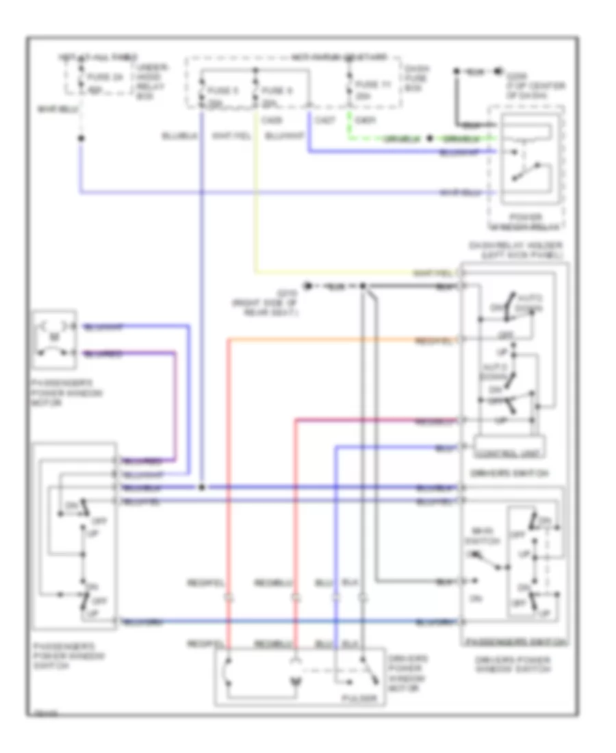
POWER WINDOWS Power Window Wiring Diagram for Honda Prelude 2.0 Si 1991 List of elements for Power Window Wiring Diagram for Honda Prelude 2.0 Si 1991: 28 20a 40a Auto down C427 C428 C431 c431 Control unit Dash fuse box Dash relay holder (left kick panel) Driver's power window motor Driver's power window switch Driver's switch driver's switch Fuse 11 Fuse 24 Fuse 5 Fuse 6 G206 (top center of dash) G310 (right side of rear seat) Hot at all times Hot in run or start Main switch Off Passenger's power window motor Passenger's power window switch Passenger's switch passenger's switch Power window relay Pulser Under- hood relay box
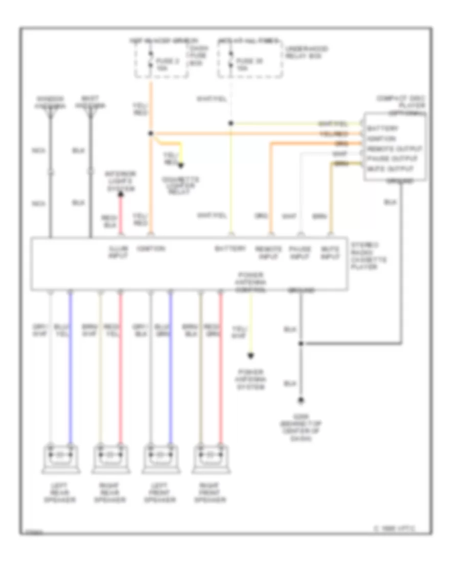
RADIO Radio Wiring Diagrams for Honda Prelude 2.0 Si 1991 List of elements for Radio Wiring Diagrams for Honda Prelude 2.0 Si 1991: 31 1995 vftc c Battery Cigarette lighter relay Compact disc player (optional) Dash fuse box Fuse 2 10a Fuse 35 10a G206 (behind top center of dash) Ground Hot at all times Hot in accy or run Ignition Illum input Interior lights system Left front speaker Left rear speaker Mast antenna Mute input Mute output Nca Pause input Pause output Power antenna control Power antenna system Remote input Remote output Right front speaker Right rear speaker Stereo radio/ cassette player Under-hood relay box Window antenna
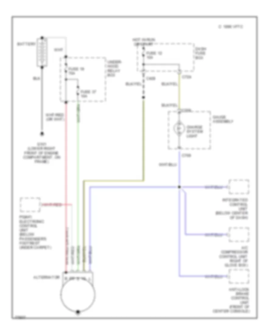
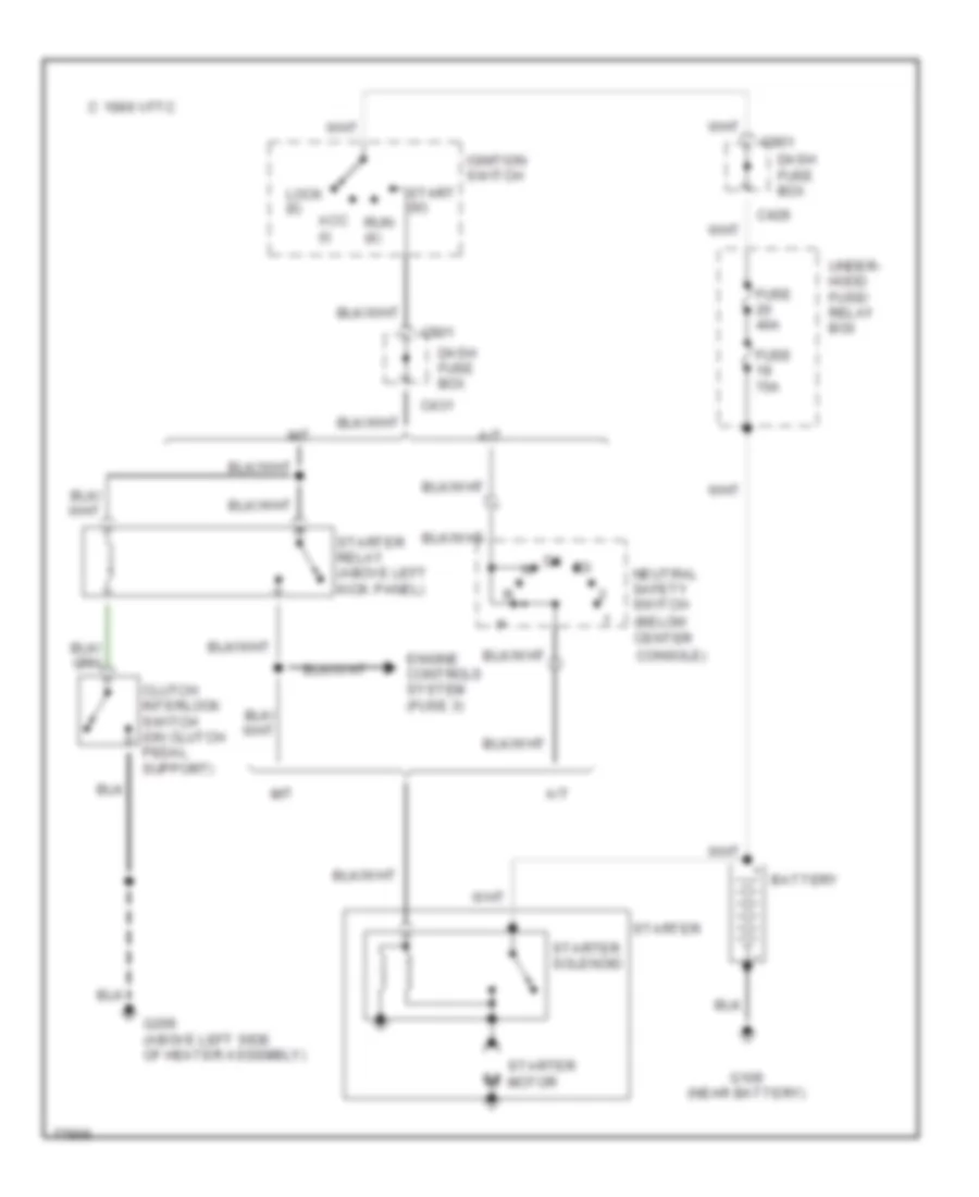
STARTING/CHARGING Charging Wiring Diagram for Honda Prelude 2.0 Si 1991 List of elements for Charging Wiring Diagram for Honda Prelude 2.0 Si 1991: 19 A/c compressor control unit right of glove box) Alternator Anti-lock brake control unit (front of center console) Battery C 1996 vftc C428 C709 C724 Charge system light Dash fuse box Fuse 12 10a Fuse 19 70a Fuse 37 10a G101 (lower right front of engine compartment, on frame) Gauge assembly Hot in run or start Integrated control unit (below center of dash) Pgm-fi electronic control unit (below passenger's footrest under carpet) Under- hood relay box Starting Wiring Diagram for Honda Prelude 2.0 Si 1991 List of elements for Starting Wiring Diagram for Honda Prelude 2.0 Si 1991: 27 (below center A/t Acc (i) Battery C 1996 vftc C429 C431 C901 Clutch interlock switch (on clutch pedal support) Console) Dash fuse box Engine controls system (fuse 3) Fuse 40a Fuse 70a G109 (near battery) G206 (above left side of heater assembly) Ignition switch Lock (0) M/t Neutral safety switch Run (ii) Start (iii) Starter Starter motor Starter relay (above left kick panel) Starter solenoid Under- hood fuse/ relay box
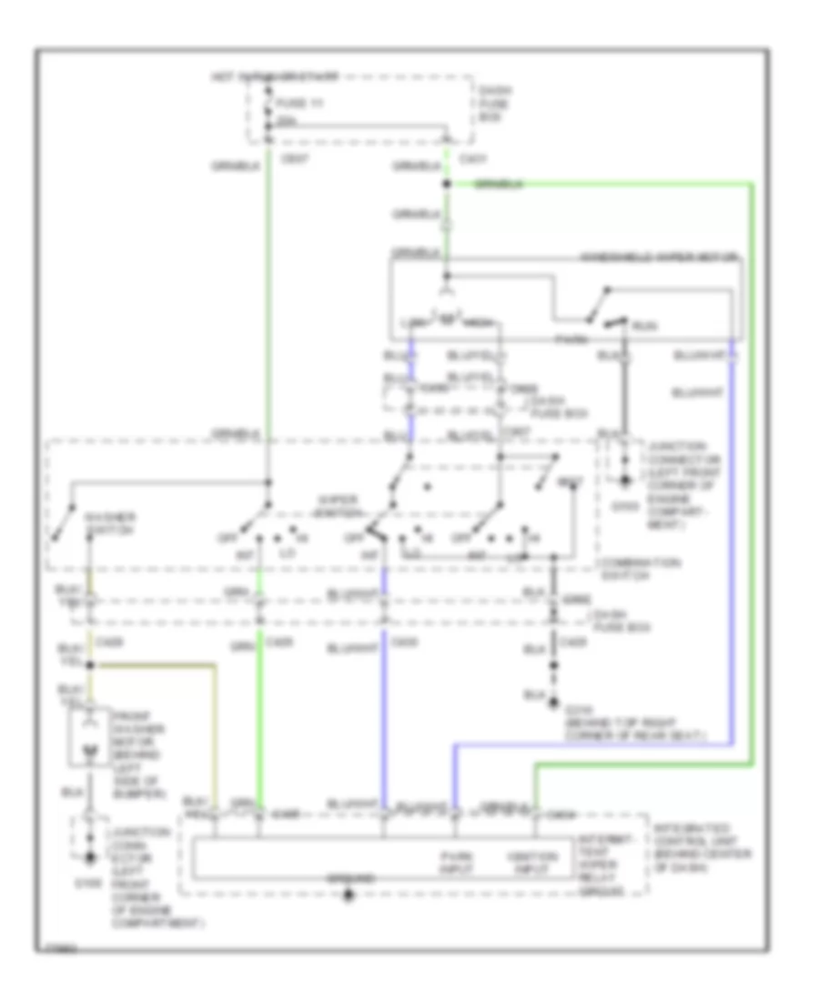
WIPER/WASHER Wiper/Washer Wiring Diagram for Honda Prelude 2.0 Si 1991 List of elements for Wiper/Washer Wiring Diagram for Honda Prelude 2.0 Si 1991: 32 20a C426 C428 C430 C431 C434 C435 C907 Combination switch Dash fuse box Front washer motor (behind left side of bumper) Fuse 11 G100 G310 (behind top right corner of rear seat) Ground High Hot in run or start Ignition input Int Integrated control unit (behind center of dash) Intermit- tent wiper relay circuit Junction conn- ector (left front corner of engine compartment) Junction connector (left front corner of engine compart- ment) Low Mist Off Park Park input Run Washer switch Windshield wiper motor Wiper switch