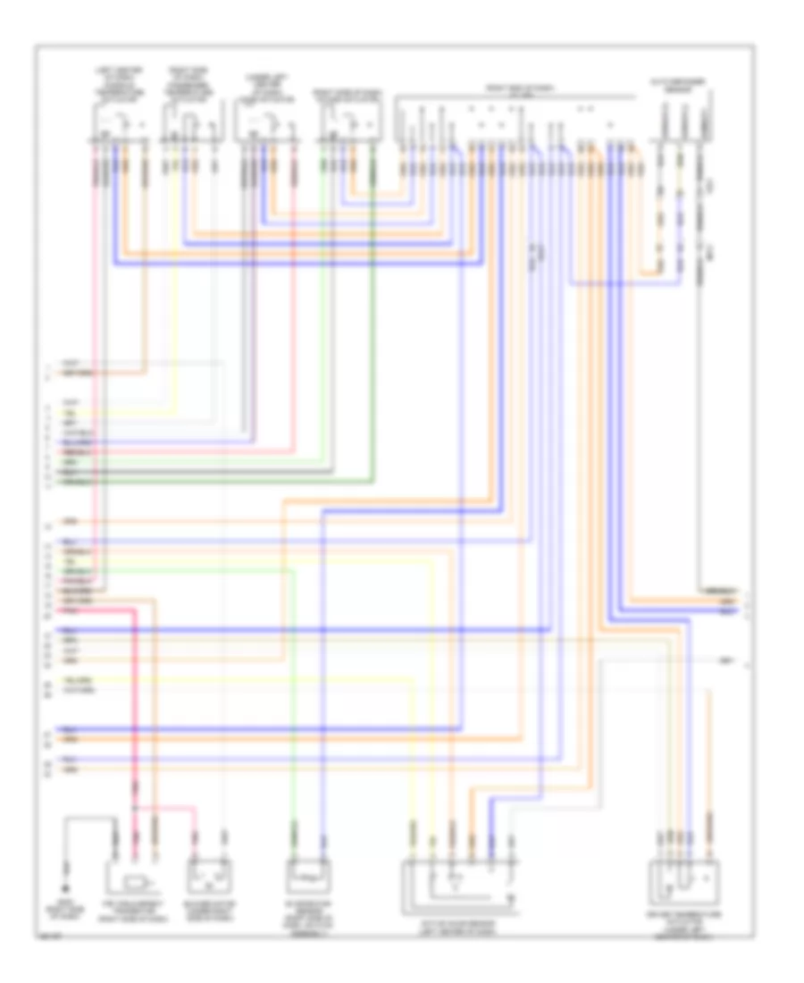
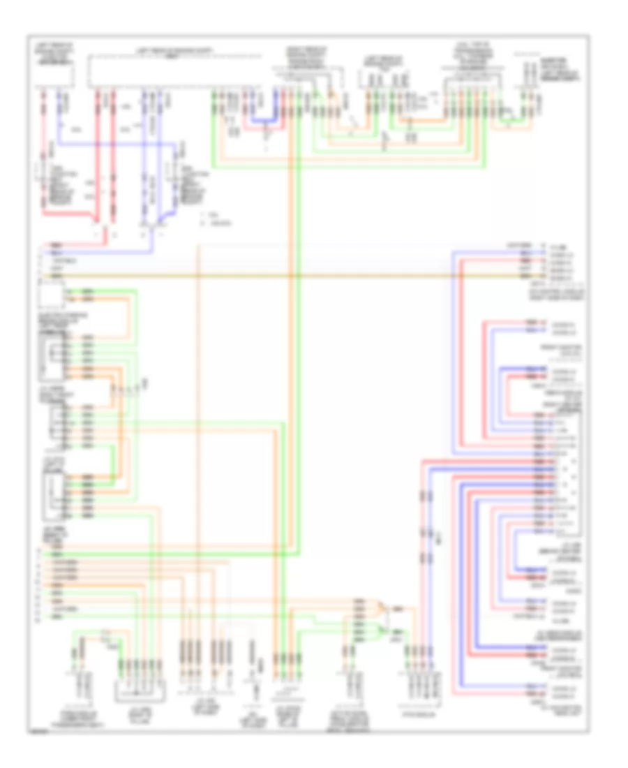
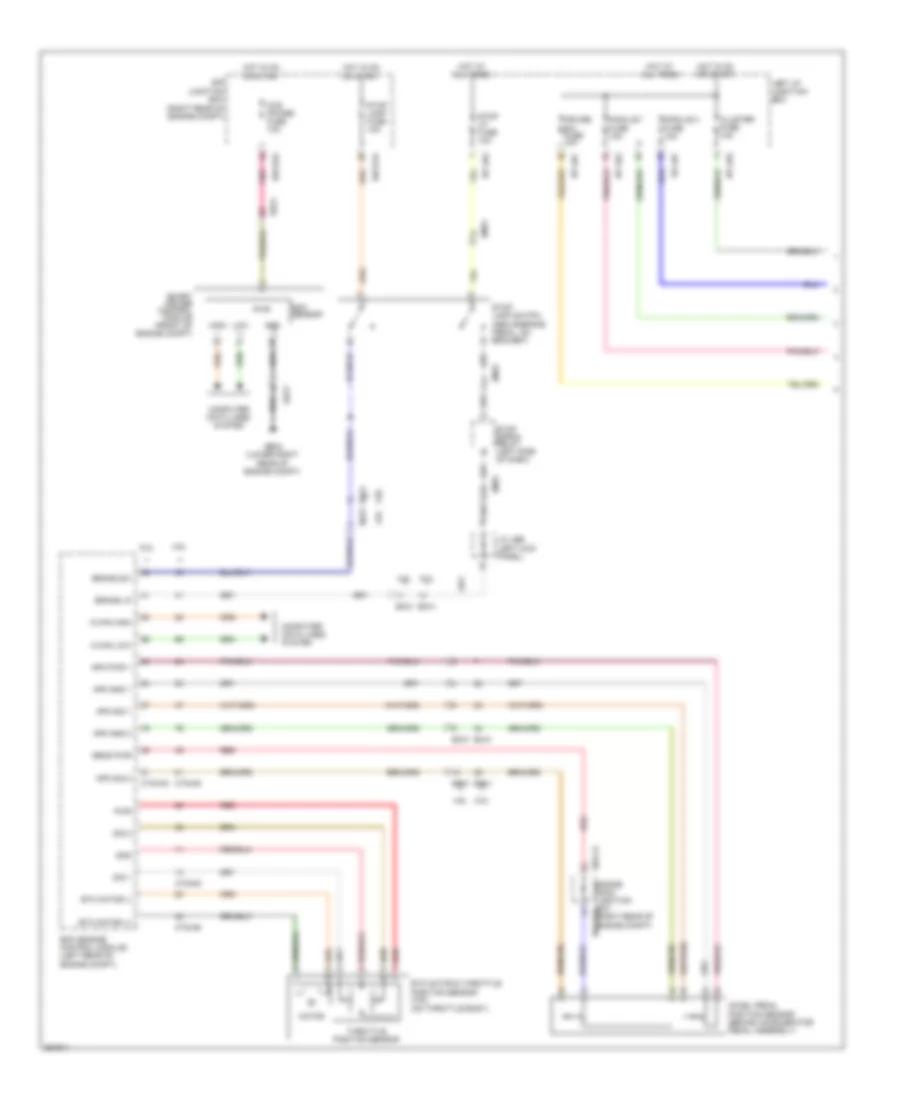
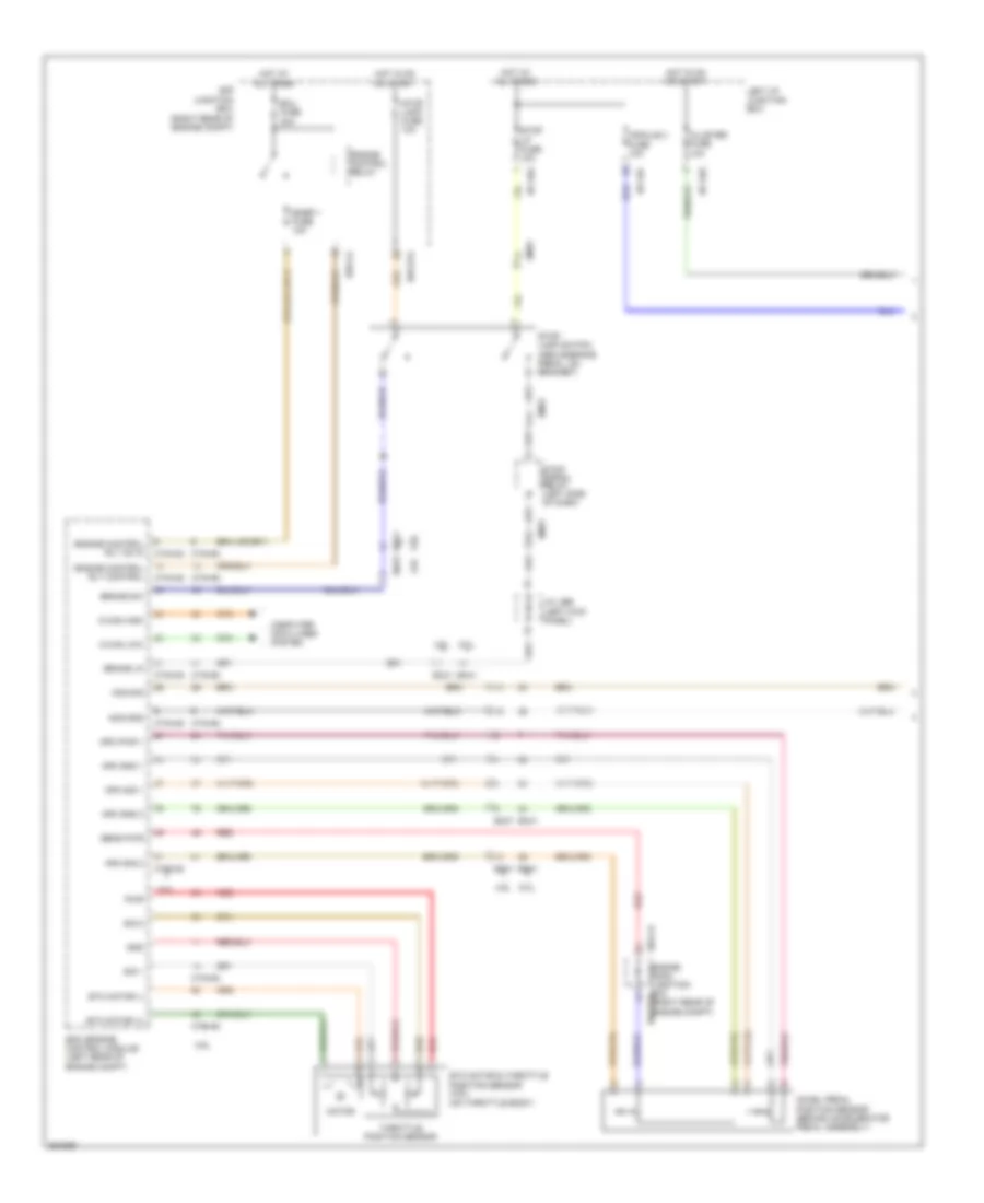
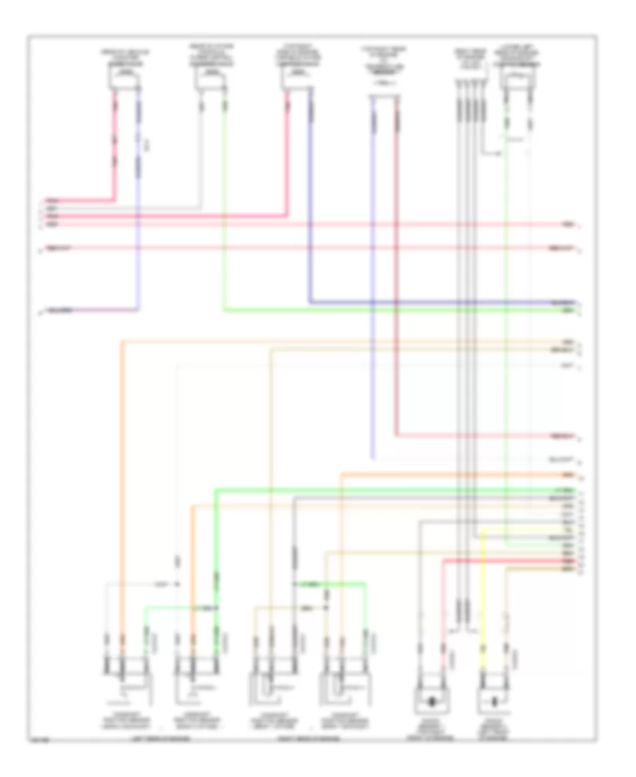
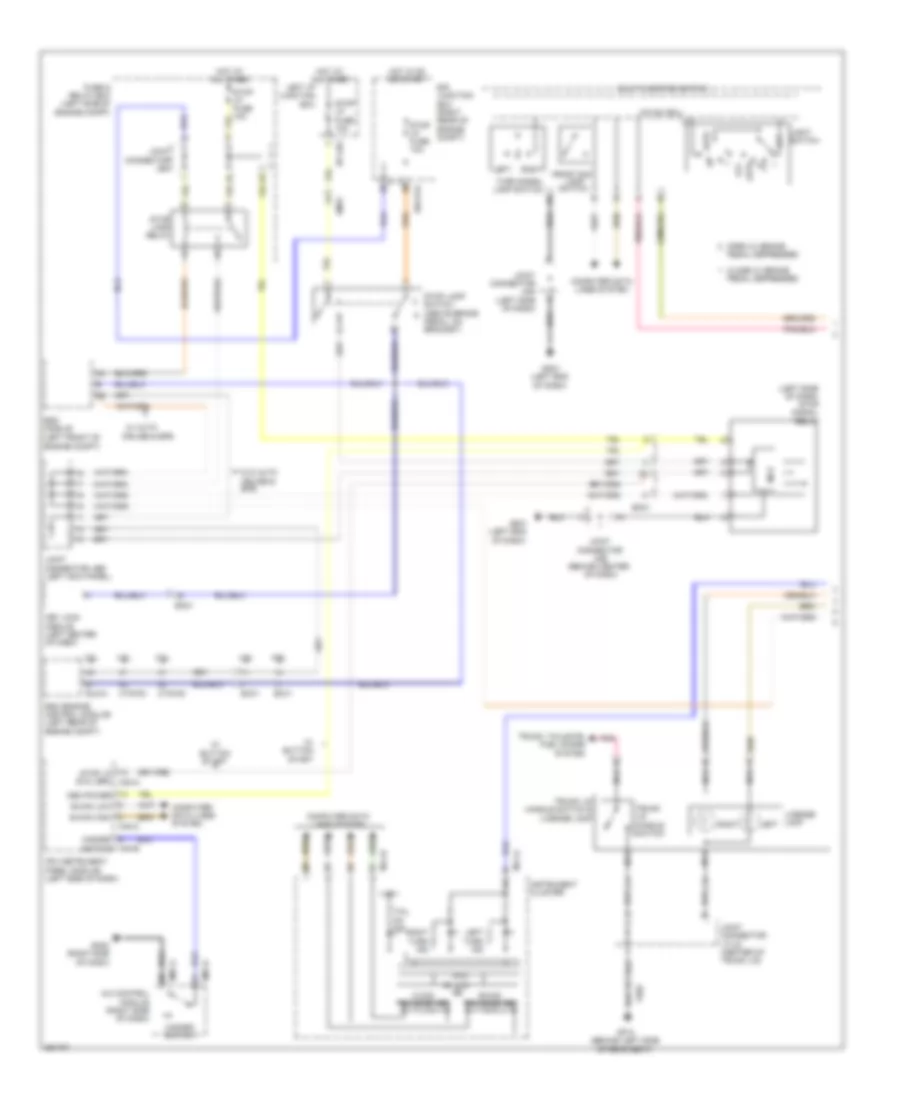
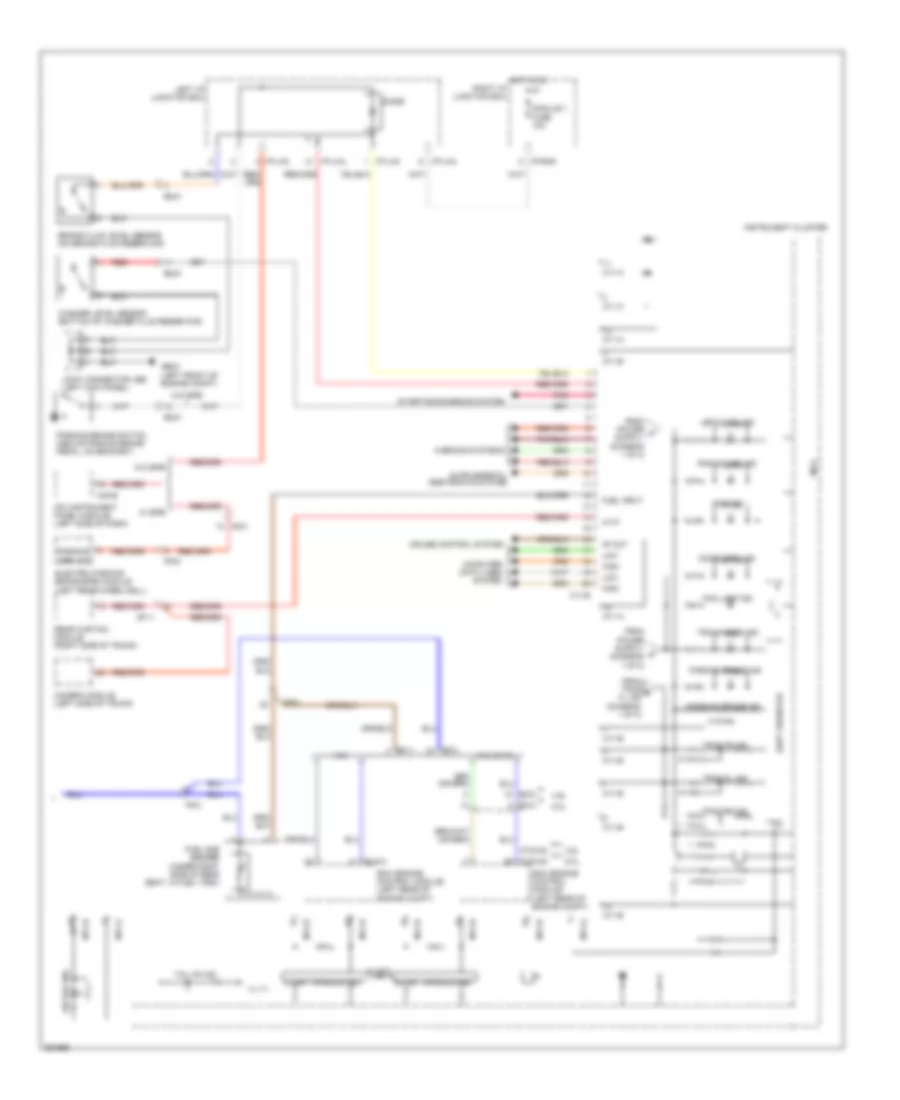
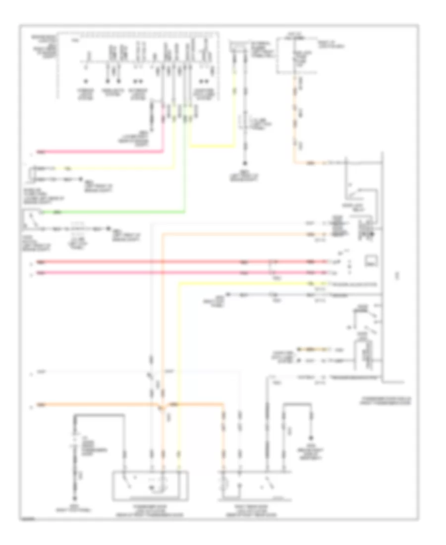
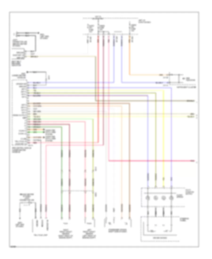
AIR CONDITIONING
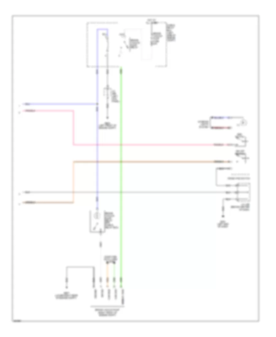
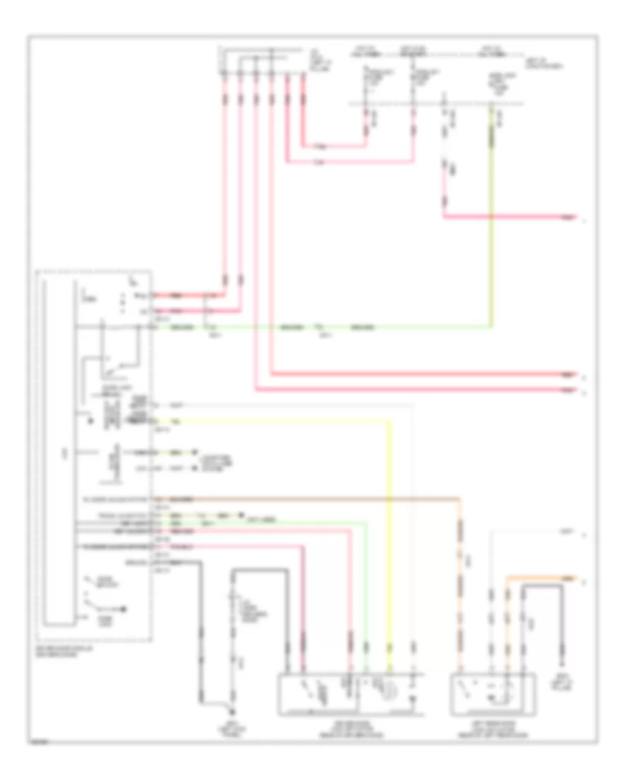
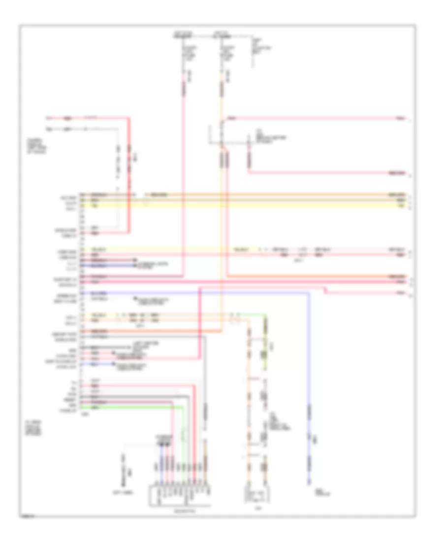
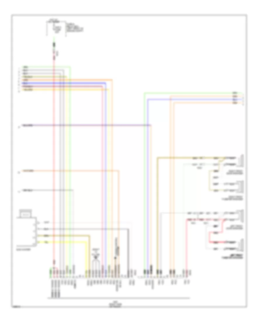
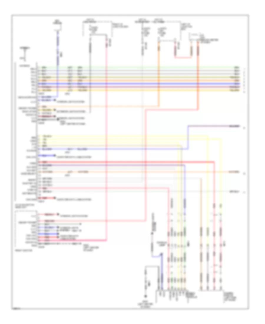
Automatic A/C Wiring Diagram (1 of 3) for Hyundai Genesis 5.0 R-Spec 2012

List of elements for Automatic A/C Wiring Diagram (1 of 3) for Hyundai Genesis 5.0 R-Spec 2012:
- (left end of dash) gm06
- (left front of engine compt) ge03
- (left kick panel) j/c jeb
- 3.8l
- 4.6l
- 5.0l
- A/c control module (right side of dash)
- A/con (b+) fuse 10a
- A/con (ig1) fuse 10a
- A/con fuse 10a
- Ambient sensor (front of engine compt)
- Aqs fuse 10a
- Aqs sensor (front of engine compt)
- Aqs signal
- B-can high
- B-can low
- Blower
- Blower relay
- Blower relay on input
- Body k-line
- Computer data lines system
- Console temperature actuator "a" (left center of dash)
- Console vent temperature actuator & switch
- Cool console temp actr
- Cool console temp actr a
- Cool temp actuator
- Def led output (htd)
- Def mode actuator
- Defogger system
- Drv photo sensor (-)
- E/r-e1b
- E/r-e2b
- Ec31
- Ec41
- Ecv (+)
- Ecv (-)
- Ee11
- Ee21
- Ee31
- Electronic a/c compressor (left front of engine)
- Em21
- Em41
- Engine room junction box (right rear of engine compt)
- Evap sensor (+)
- F/b
- F/b console temp actr a
- F/b console temp actuator
- F/b intake actuator
- F/b mode actuator
- F/b temp actuator
- Fet (d)
- Fet (g)
- Fre intake actuator
- Fuse 40a
- Ge04 (lower right rear of engine compt)
- Gm02 (right side of dash)
- Ground
- Hot at all times
- Hot in on
- Hot in on or start
- Humidity sensor (+)
- I/p-lhc
- I/p-lhg
- Ill (+)
- Ill (-)
- Incar sensor (+)
- Interior lights system
- J/c jcsex (under center console)
- Left i/p junction block
- M07-a
- M07-b
- Memory power
- Mm-can high
- Mm-can low
- Mm11
- Motor (-)
- Nca
- On/start input
- Out dr temp sensor
- Pass photo sensor (-)
- Photo sensor (top right side of dash)
- Pnk
- Rec intake actuator
- Red
- Sensor ground
- Sensor ref (+5)
- Vent mode actuator
- Vent switch
- Vent switch signal
- Vent temperature actuator
- Warm console temp actr
- Warm console temp actr a
- Warm temp actuator
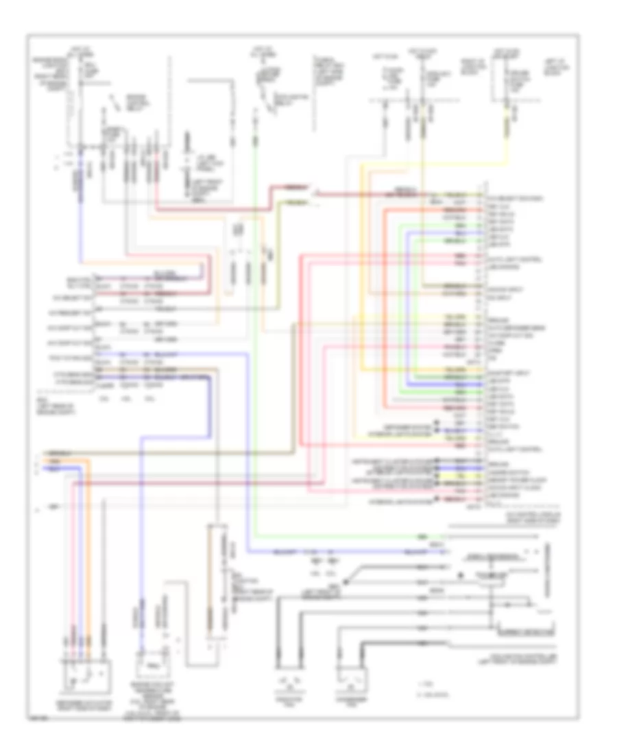
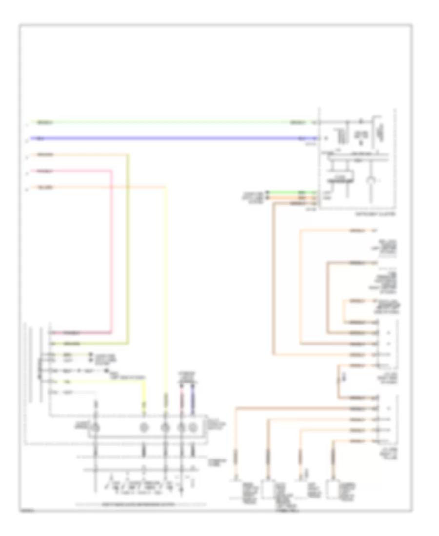
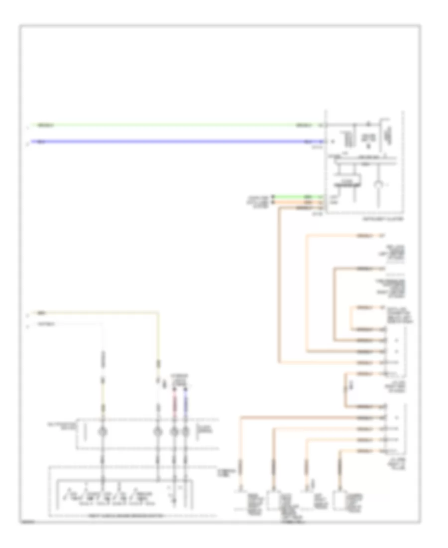
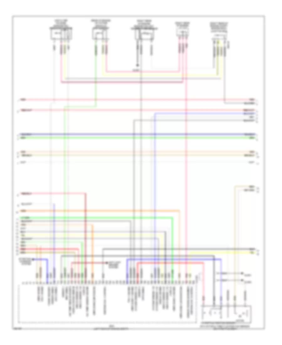
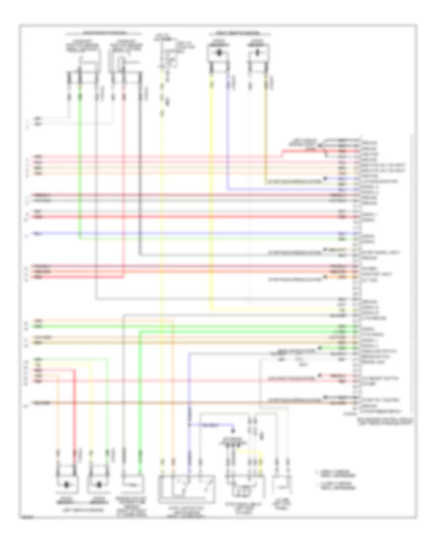
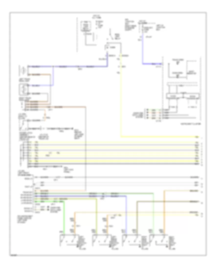
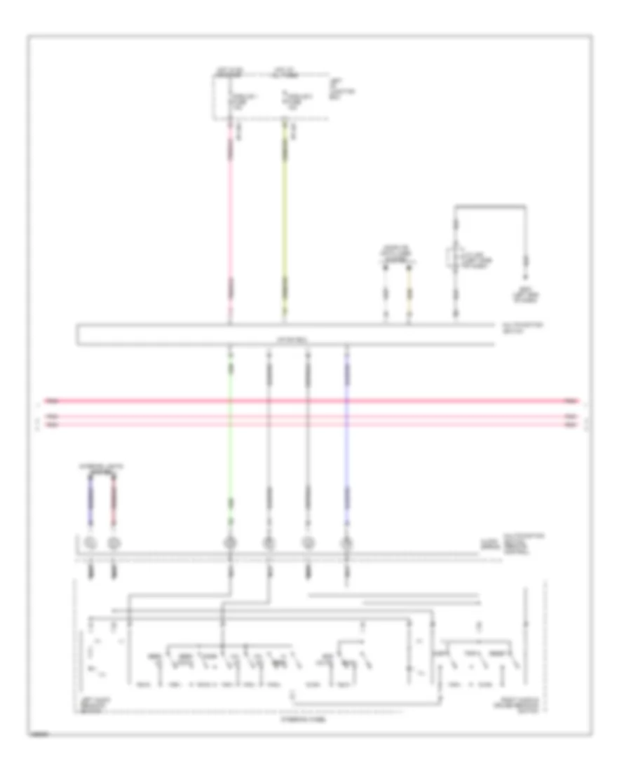
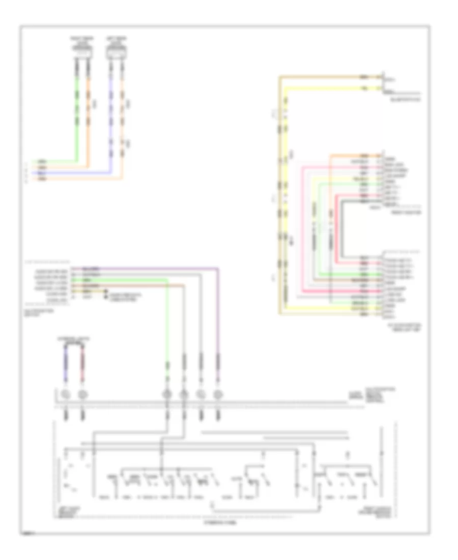
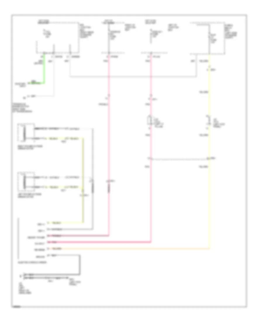
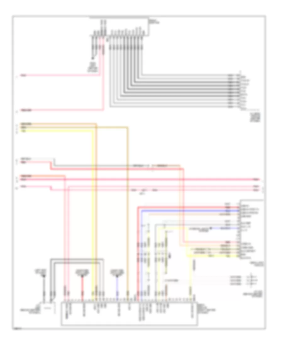
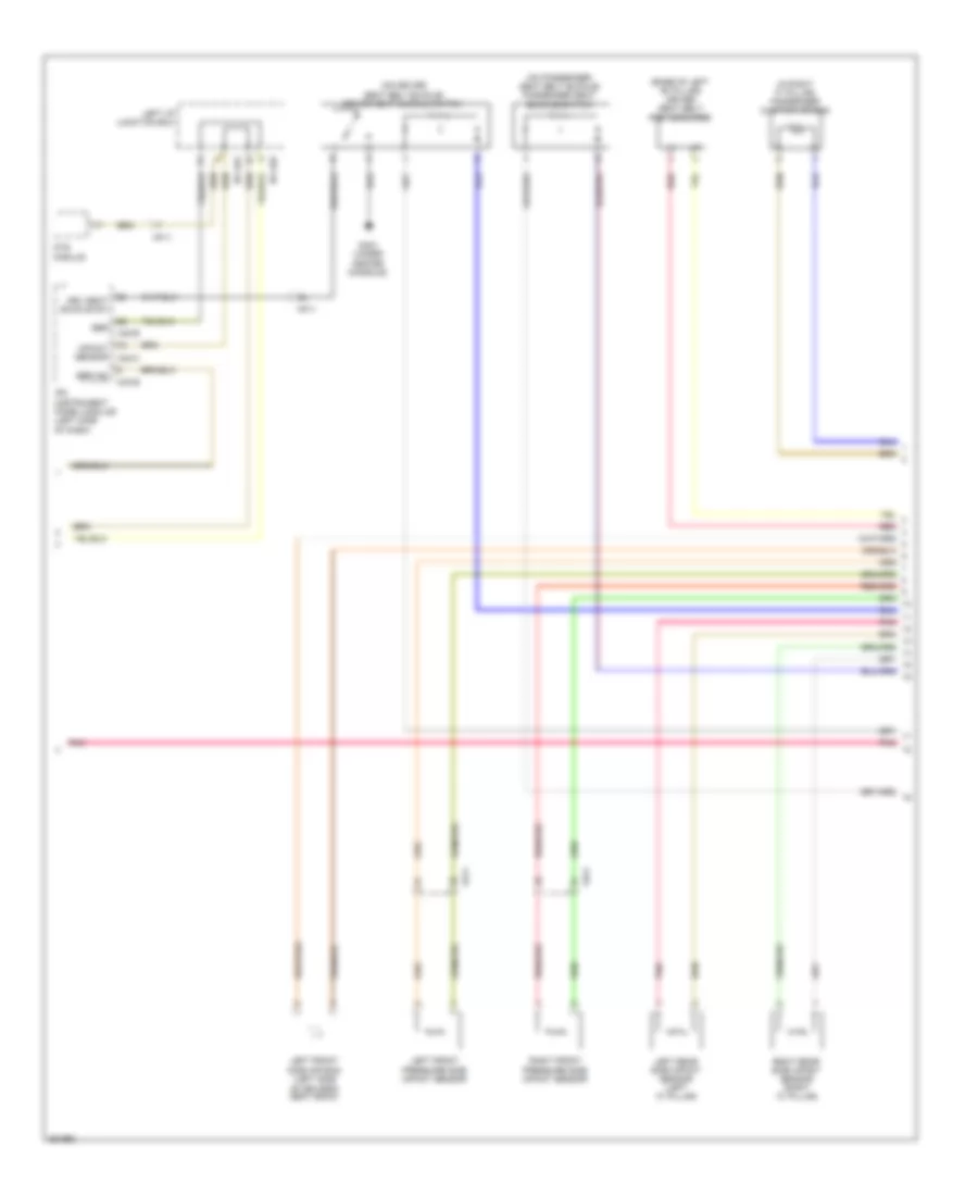
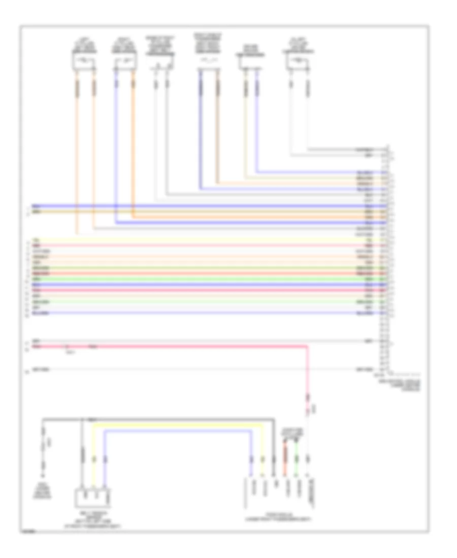
Automatic A/C Wiring Diagram (2 of 3) for Hyundai Genesis 5.0 R-Spec 2012
List of elements for Automatic A/C Wiring Diagram (2 of 3) for Hyundai Genesis 5.0 R-Spec 2012:
- (left center of dash) console temperature actuator
- (right end of dash) j/c jmg
- (right side of dash) intake actuator
- (right side of dash) passenger temperature actuator
- (under left center of dash) mode actuator
- Active incar sensor (left center of dash)
- Auto defogger sensor
- Blower motor (under right side of dash)
- Driver temperature actuator (under left center of dash)
- Ee41
- Evaporator sensor (right side of dash, on hvac assembly)
- Fet (field effect transistor) (right side of dash)
- Fr21
- Gm02 (right side of dash)
- Humidity
- Mf21
- Pnk
- Sensor (+)
- Sensor (-)
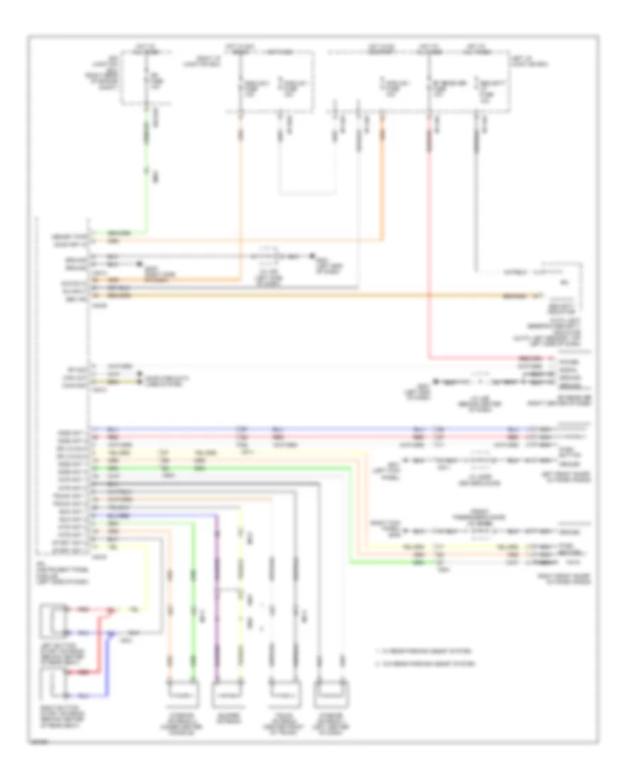
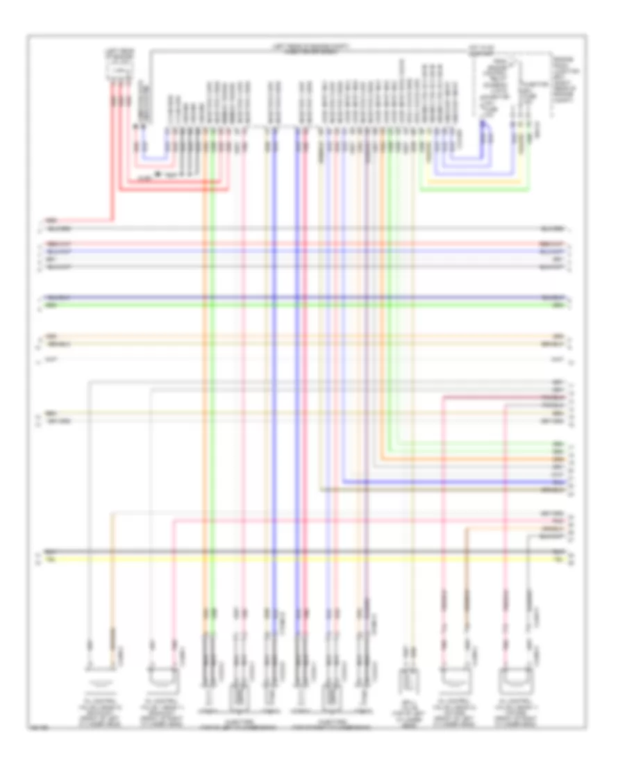
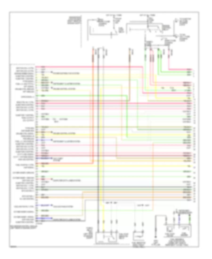
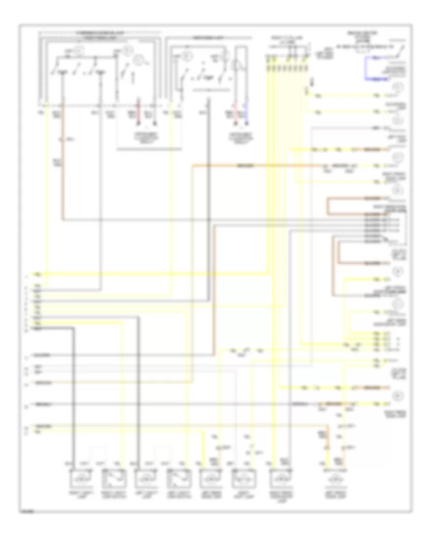
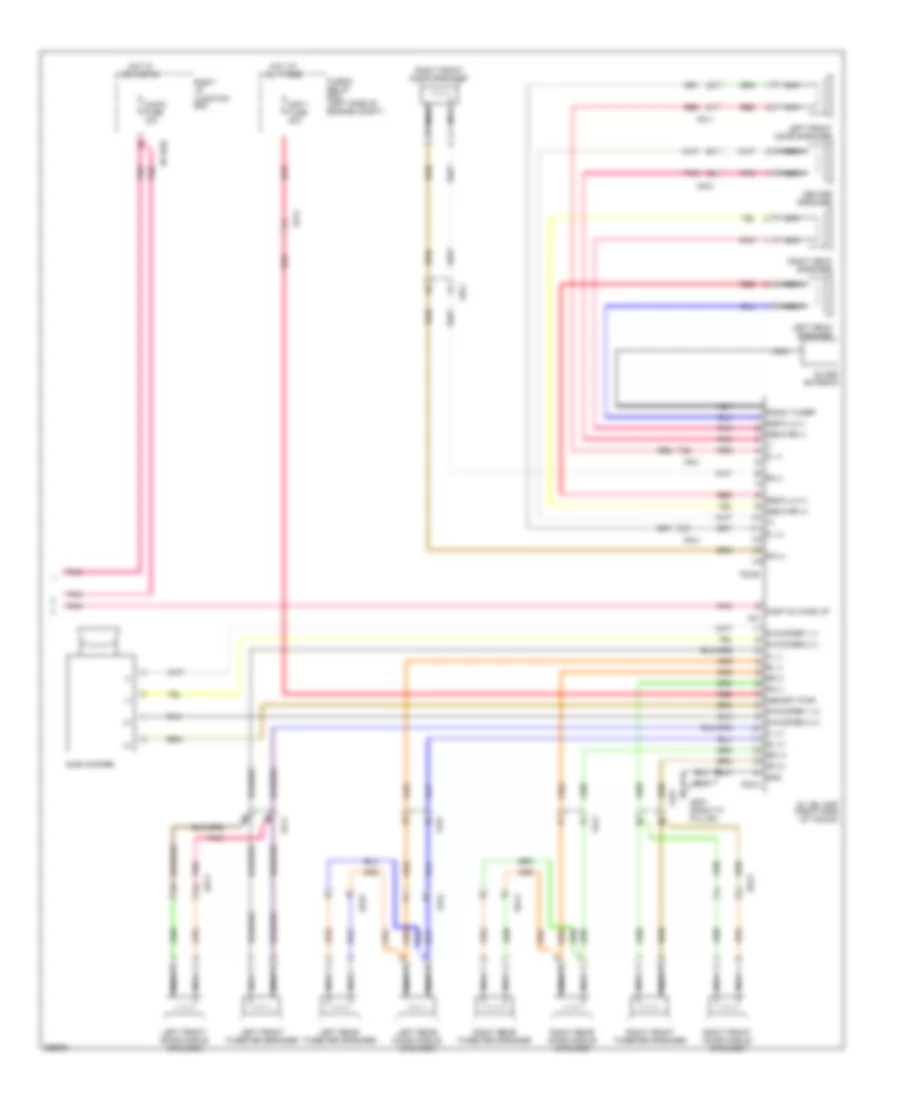
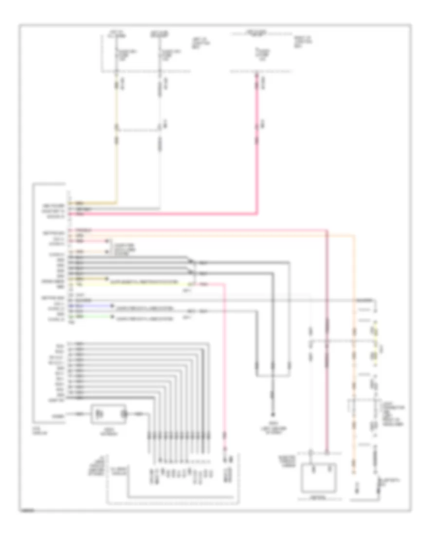
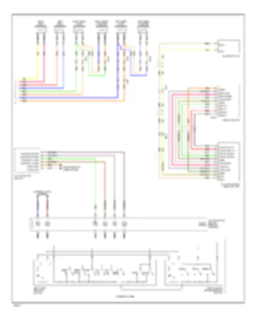
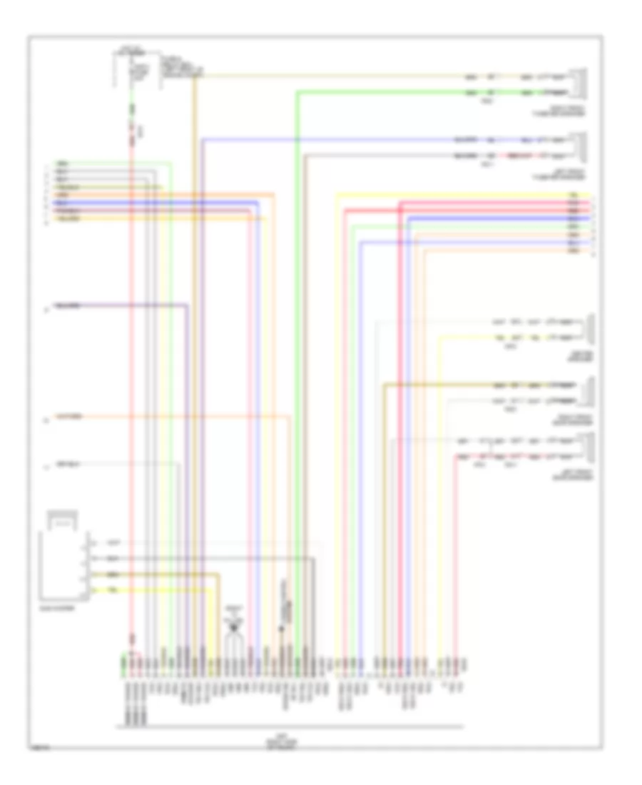
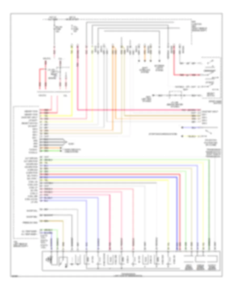
Automatic A/C Wiring Diagram (3 of 3) for Hyundai Genesis 5.0 R-Spec 2012
List of elements for Automatic A/C Wiring Diagram (3 of 3) for Hyundai Genesis 5.0 R-Spec 2012:
- (left front
- 3.8l
- 4.6l
- 4.6l & 5.0l
- 5.0l
- A/c comp cut sig
- A/c comp cut sig elg-a
- A/c control module (right side of dash)
- A/c request sw
- A/c select sig (high)
- A/c select sw
- A/con (ig2) fuse 10a
- Acc/on input
- Acc/on input clock
- Auto defogger sens
- Auto light control
- C/fan fuse 60a
- Close
- Condenser fan
- Cooling fan controller (left front of engine compt)
- Cooling fan relay
- Cruise switch fuse 10a
- Ctg-ag
- Ctg-am
- Ctg-kg
- Ctg-km
- Current detecting
- Def switch
- Defogger actuator (right side of dash)
- Defogger system
- E/r junction box (right rear of
- E/r-ca
- E/r-cb
- E/r-e2a
- E05-a
- E05-b
- Ec31
- Ec41
- Ecm (left rear of
- Ecu fuse 30a
- Elg-a a/c comp cut sig
- Em41
- Eng ctrl rly ctrl elg-a
- Engine compt)
- Engine compt) e/r-cb
- Engine control relay
- Engine coolant temperature sensor (3.8l: right rear of engine) (4.6l & 5.0l: front of right cylinder head)
- Engine room junction box (right rear
- F/b
- Fuse & relay box (left side
- Ge01 (left front of engine compt)
- Ge03
- Ground
- Hazard switch
- Hot at all times
- Hot in acc or on
- Hot in on
- Hot in on or start
- I/p-lhc
- I/p-rhb
- I/p-rhd
- Ill (+)
- Ill (-)
- Instrument cluster & power distribution systems
- Instrument cluster & power distribution systems exterior lights system
- Interior lights system
- J/c jeb (left kick panel)
- Key clk
- Key data
- Key sh/ld
- Led clk
- Led data
- Led dimming
- Led str
- Left i/p junction block
- M07-c
- M07-d
- Memory power clock
- Module 2 fuse 10a
- Nca
- Of engine compt)
- On input
- On/start input
- Open
- Pnk
- Power conditioning
- Pwm to fan mod elg-a
- Pwn driver
- Radiator fan
- Red
- Right i/p junction block
- Signal processing
- Snsr 2 fuse 10a
- Wts sens gnd
- Wts sens sig clg-bg
ANTI-LOCK BRAKES
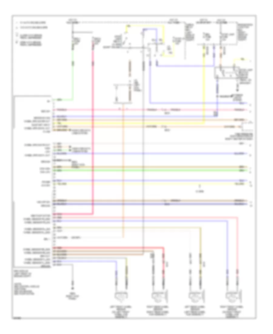
Anti-lock Brakes Wiring Diagram (1 of 3) for Hyundai Genesis 5.0 R-Spec 2012
List of elements for Anti-lock Brakes Wiring Diagram (1 of 3) for Hyundai Genesis 5.0 R-Spec 2012:
- (above
- (left side of engine compt)
- (note: esc control module contains: esc solenoids, esc pump motor)
- (w/ epb
- Abs pump motor
- Avh sw
- Bracket)
- Brake pedal, on
- Brake sw sig
- Brk out
- Brl 1
- Can high
- Can low
- Close with brake pedal depressed
- Computer data lines system
- E/r-e1a
- E/r-e2b
- Ef21
- Ef31
- Em21
- Em31
- Engine room junction box (right rear of engine compt)
- Esc fuse 10a
- Esc module (left front of engine compt)
- Esc sw
- Esc-2 fuse 30a pnk
- Exterior lights system
- Fuse & relay box
- Ge02 (right kick panel)
- Ground
- High
- Hot at all times
- Hot in on or start
- J/c jea
- J/c jeb (left kick panel)
- K-line
- Left front wheel sensor (on left front wheel hub assembly)
- Left rear wheel sensor (left rear wheel hub assembly)
- Low
- Nca
- On/start input
- Open with brake pedal depressed
- Pnk
- Power
- Red
- Right front wheel sensor (on right front wheel hub assembly)
- Right rear wheel sensor (right rear wheel hub assembly)
- Smart cruise)
- Stop lamp
- Stop lamp fuse 10a
- Stop lamp relay
- Stop lp fuse 10a
- Switch
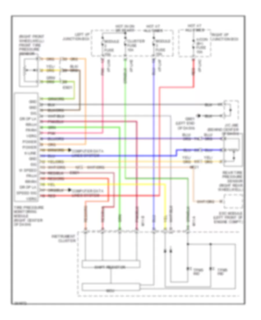
- Tire pressure monitoring module (right center of dash)
- Vsm off sw
- W/ auto cruise & epb
- W/ epb
- W/o auto cruise & epb
- Wheel sensor fl_gnd
- Wheel sensor fl_sig
- Wheel sensor fr_gnd
- Wheel sensor fr_sig
- Wheel sensor rl_gnd
- Wheel sensor rl_sig
- Wheel sensor rr_gnd
- Wheel sensor rr_sig
- Wheel spd sig fl out
- Wheel spd sig fr out
- Wheel spd sig rl out
- Wheel spd sig rr out
Anti-lock Brakes Wiring Diagram (2 of 3) for Hyundai Genesis 5.0 R-Spec 2012
List of elements for Anti-lock Brakes Wiring Diagram (2 of 3) for Hyundai Genesis 5.0 R-Spec 2012:
- 3.8l
- 4.6l
- 5.0l
- Abs ind
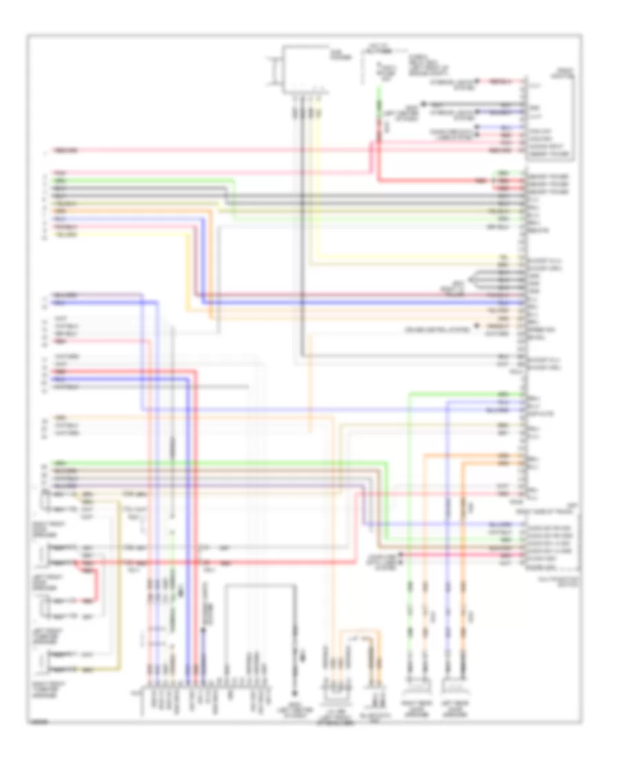
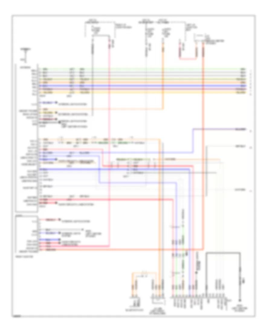
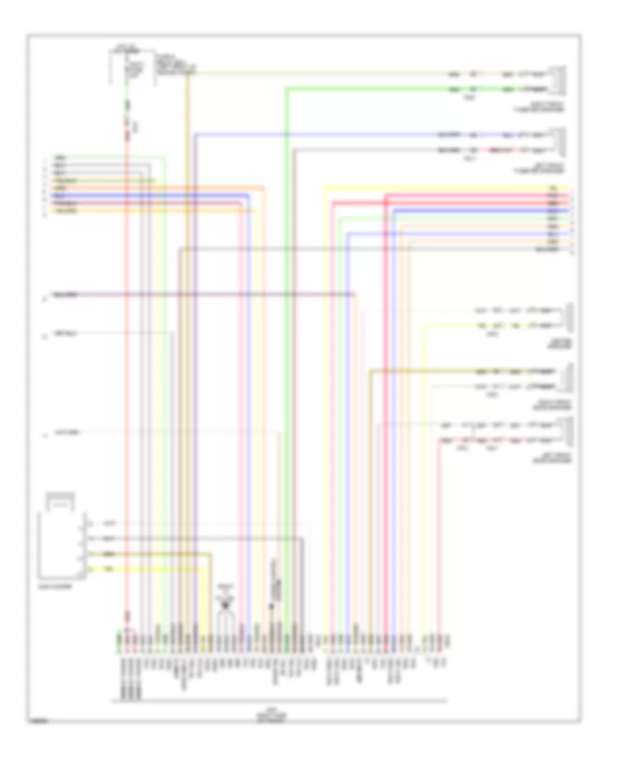
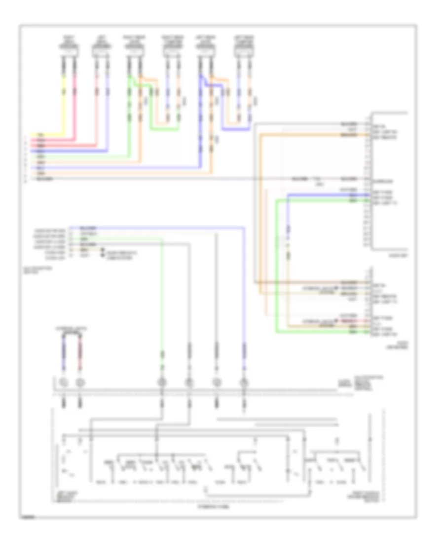
- Av & navigation head unit
- Av head module (center of dash)
- Avh
- Can high
- Can low
- Clg-bg
- Cluster fuse 10a
- Computer data lines system
- Ctg-kg
- Ctg-km
- Diode
- Ec21
- Ec31
- Ec41
- Ecm (left rear of engine compt)
- Ef31
- Em31
- Em41
- Epb & avh switch
- Esc ind
- Esc off ind
- Gm01 (left end of dash)
- Ground
- Hot at all times
- Hot in on or start
- I/p-lhc
- I/p-lhe
- I/p-lhf
- I/p-lhg
- Ill.
- Instrument cluster
- Instrument cluster sensor (under center console)
- Interior lights system
- J/c jme (behind center of dash)
- Left i/p junction box
- M11-a
- M11-b
- M25-e
- M51-b
- Mcu
- Module 2 fuse 10a
- Navi
- Parking brake ind
- Parking brake switch (w/o epb) (above parking brake pedal, on bracket)
- Pdm (left center of dash)
- Power
- Shift resistor
- Steering angle sensor (on steering column)
- Stop lp fuse 10a
- Switch
- Vsm off ind
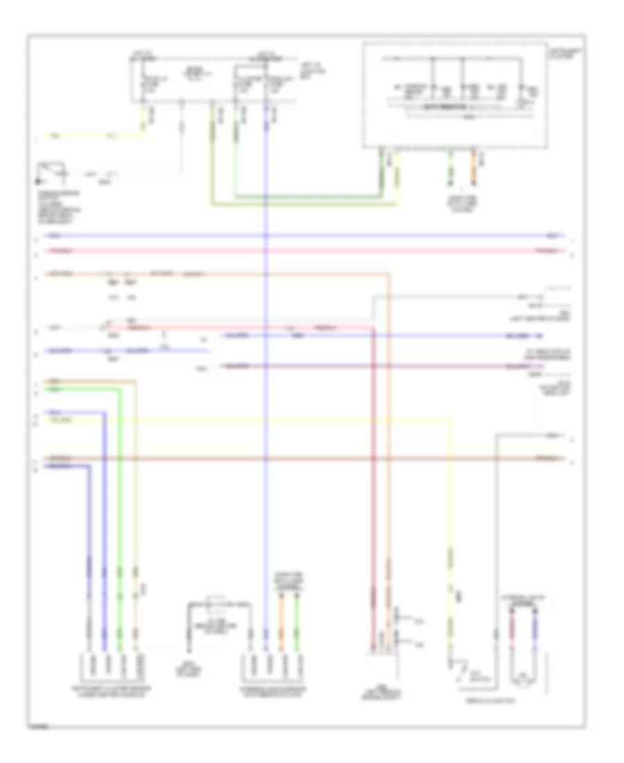
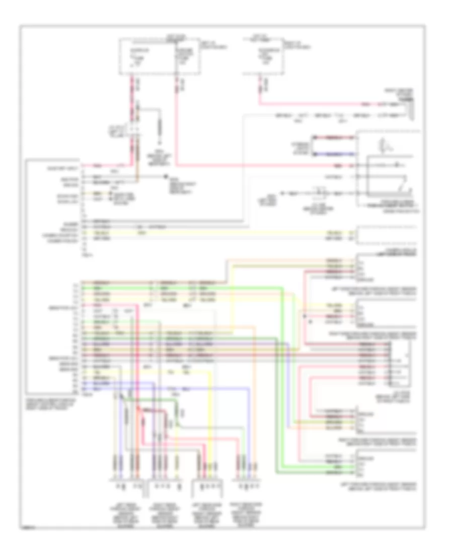
Anti-lock Brakes Wiring Diagram (3 of 3) for Hyundai Genesis 5.0 R-Spec 2012
List of elements for Anti-lock Brakes Wiring Diagram (3 of 3) for Hyundai Genesis 5.0 R-Spec 2012:
- Brake vacuum pump (right front of engine compt)
- Brake vacuum pump fuse 20a
- Brake vacuum pump relay
- Brake vacuum pump relay (e/r fuse & relay box)
- Can high
- Can low
- Compt)
- Computer data lines system
- Crash pad switch
- Esc switch
- Fuse & relay box (left side of engine
- Ge03 (left front of engine compt)
- Ge07 (lower right rear of engine compt)
- Gm01 (left end of dash)
- Ground
- Hot at all times
- Ill
- Interior lights system
- J/c jeb (left kick panel)
- J/c jme (behind center of dash)
- Memory pwr
- Sw sig
- Vsm off switch
ANTI-THEFT
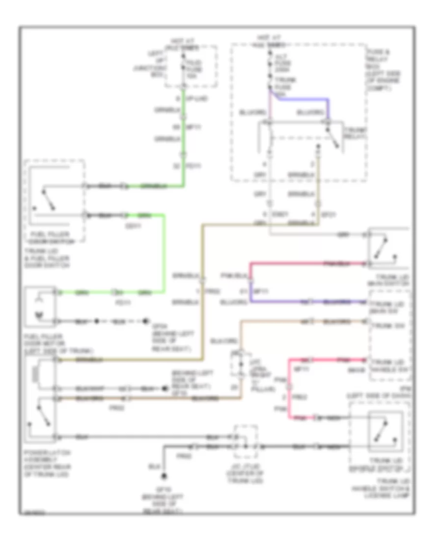
Forced Entry Wiring Diagram (1 of 2) for Hyundai Genesis 5.0 R-Spec 2012
List of elements for Forced Entry Wiring Diagram (1 of 2) for Hyundai Genesis 5.0 R-Spec 2012:
- (not used)
- Computer data lines system
- Cpu
- D01-a
- D01-b
- D01-c
- Dd11
- Door lock
- Door lock relay
- Door unlock
- Door unlock relay
- Dr lock drv fuse 10a
- Driver door lock actuator (rear of driver's door)
- Driver door module (driver's door)
- Driver ips motor
- Em21
- Fd11
- Fd31
- Fl door unlock state
- Gf01 (left kick panel)
- Gf03 (left "c" pillar)
- Ground
- High
- Hot at all times
- Hot in on or start
- I/p-lhf
- I/p-lhg
- Ig1
- J/c jddri (driver's door)
- J/c jfla (left "c" pillar)
- Key
- Key lock
- Key unlock
- Left i/p junction box
- Left rear door lock actuator (rear of left rear door)
- Lock
- Lock/ unlock
- Low
- Mf11
- Module 1 fuse 10a
- Module 3 fuse 10a
- Pnk
- Red
- Reg
- Rl door unlock state
- Transceiver b-can
- Trunk lid switch
- Unlock
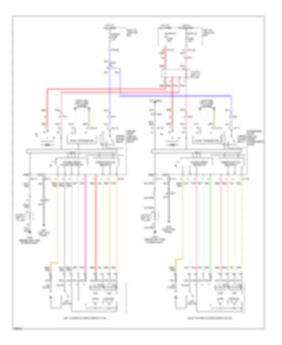
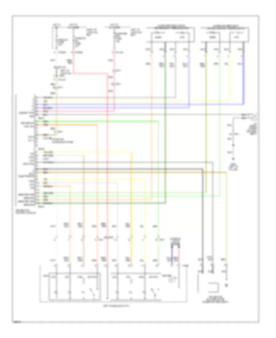
Forced Entry Wiring Diagram (2 of 2) for Hyundai Genesis 5.0 R-Spec 2012
List of elements for Forced Entry Wiring Diagram (2 of 2) for Hyundai Genesis 5.0 R-Spec 2012:
- B-can
- B/a horn
- Burglar alarm horn (lower left rear of engine compt)
- Computer data lines system
- Cpu
- D11-a
- D11-c
- Door
- Door lock
- Door lock relay door unlock relay
- Dr lock pass fuse 15a
- Driver ips motor
- E/r-e1a
- E/r-e1b
- Engine room junction box (right rear of engine compt)
- Ext buzzer
- Exterior lights system
- External buzzer (left front wheelwell)
- Fam
- Fam-a
- Fam-b
- Fam-c
- Fd21
- Fd41
- Fr door unlock state
- Ge03 (left front of engine compt)
- Ge04 (lower right rear of engine compt)
- Gf05 (right kick panel)
- Gf09 (behind right side of rear seat)
- Gnd
- Ground
- Headlights system
- High
- Hood sw
- Hood switch (left front of engine compt)
- Hot at all times
- I/p-rhb
- Ig1
- Ill(+)
- Interior lights system
- J/c jdass (front passenger's door)
- J/c jeb (left kick panel)
- Lh head lamp hi
- Lh tail lp
- Low
- Mf21
- Nca
- On/start input
- Passenger door lock actuator (rear of front passenger's door)
- Passenger door module (front passenger's door)
- Pnk
- Red
- Reg
- Relay
- Rh head lamp hi
- Rh tail lp
- Right i/p junction box
- Right rear door lock actuator (rear of right rear door)
- Rr door unlock state
- Transceiver b-can
- Unlock
Immobilizer Wiring Diagram, with Button Start for Hyundai Genesis 5.0 R-Spec 2012
List of elements for Immobilizer Wiring Diagram, with Button Start for Hyundai Genesis 5.0 R-Spec 2012:
- (front passenger's door) j/c jdass
- (right kick panel) gf05
- Acc/on in
- Auto light sensor & security indicator (auto light sensor: top left side of dash)
- Bum ant 1
- Bum ant 2
- Bumper antenna
- Button
- Can-high
- Can-low
- Computer data lines system
- Dr lk/unlk
- E/r junction box (right rear of engine compt)
- E/r-e2b
- Em31
- Fd11
- Fd21
- Fr31
- Fr32
- Gf01 (left kick
- Gm01 (left end of dash)
- Gm05 (right side of dash)
- Ground
- Hot at all times
- Hot in acc or on
- Hot in on
- Hot in on or start
- I/p-lha
- I/p-lhd
- I/p-lhg
- I/p-rhd
- Interior antenna 1 (left center of dash)
- Interior antenna 2 (under center console)
- Intr ant 1
- Intr ant 2
- Ipm (instrument panel module) (left side of dash)
- Ipm fuse 10a
- J/c jddri (driver's door)
- J/c jmd (left side of dash)
- J/c jme (behind center of dash)
- Left button start antenna (behind center of rear seat)
- Left front smart outside handle
- Left i/p junction box
- M40-a
- M40-b
- M40-c
- M40-d
- Memory pwr
- Mf11
- Mf21
- Module 1 fuse 10a
- Module 2 fuse 10a
- Nca
- On input
- On/start in
- Panel)
- Power
- Push
- Push button
- Red
- Rf com
- Rf receiver (right center of dash)
- Rf receiver fuse 10a
- Right button start antenna (behind center of rear seat)
- Right front smart outside handle
- Right i/p junction box
- Sec ind
- Security indicator
- Security lp fuse 10a
- Side ant 1
- Side ant 2
- Signal
- Start ant 1
- Start ant 2
- Trunk ant 1
- Trunk ant 2
- Trunk antenna (center front of trunk)
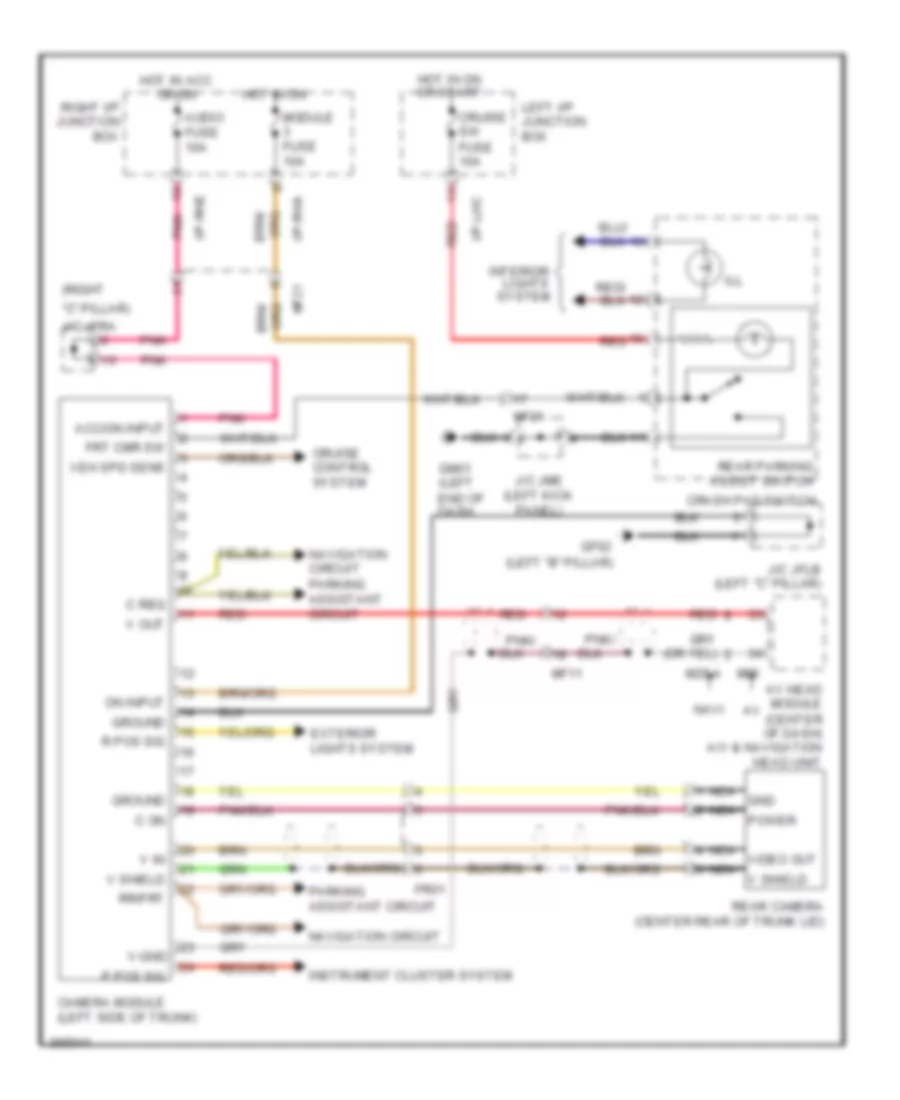
- W/ rear parking assist system
- W/o rear parking assist system
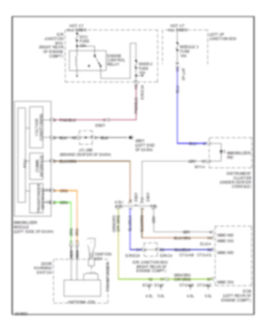
Immobilizer Wiring Diagram, without Button Start for Hyundai Genesis 5.0 R-Spec 2012
List of elements for Immobilizer Wiring Diagram, without Button Start for Hyundai Genesis 5.0 R-Spec 2012:
- (+)
- (-)
- 3.8l
- 4.6l
- 4.6l/ 5.0l
- 5.0l
- Antenna coil
- Comms interface
- Ctg-ag
- Ctg-am
- Ctg-kg
- Ctg-km
- Door warning switch
- E/r junction box (right rear of engine compt)
- E/r-ca
- E/r-e2a
- Ec31
- Ec41
- Ecm (left rear of engine compt)
- Ecu fuse 30a
- Elg-a
- Em21
- Em31
- Engine control relay
- Gm01 (left end of dash)
- Hot at all times
- I/p-lhf
- Ignition key
- Immo ind
- Immo sig
- Immobilizer ind
- Immobilizer module (left side of dash)
- Instrument cluster (under center console)
- J/c jme (behind center of dash)
- Left i/p junction box
- M11-a
- Module 3 fuse 10a
- Nca
- Pcu
- Snsr 2 fuse 10a
- Transponder
- Transponder interface
- Voltage conditioning
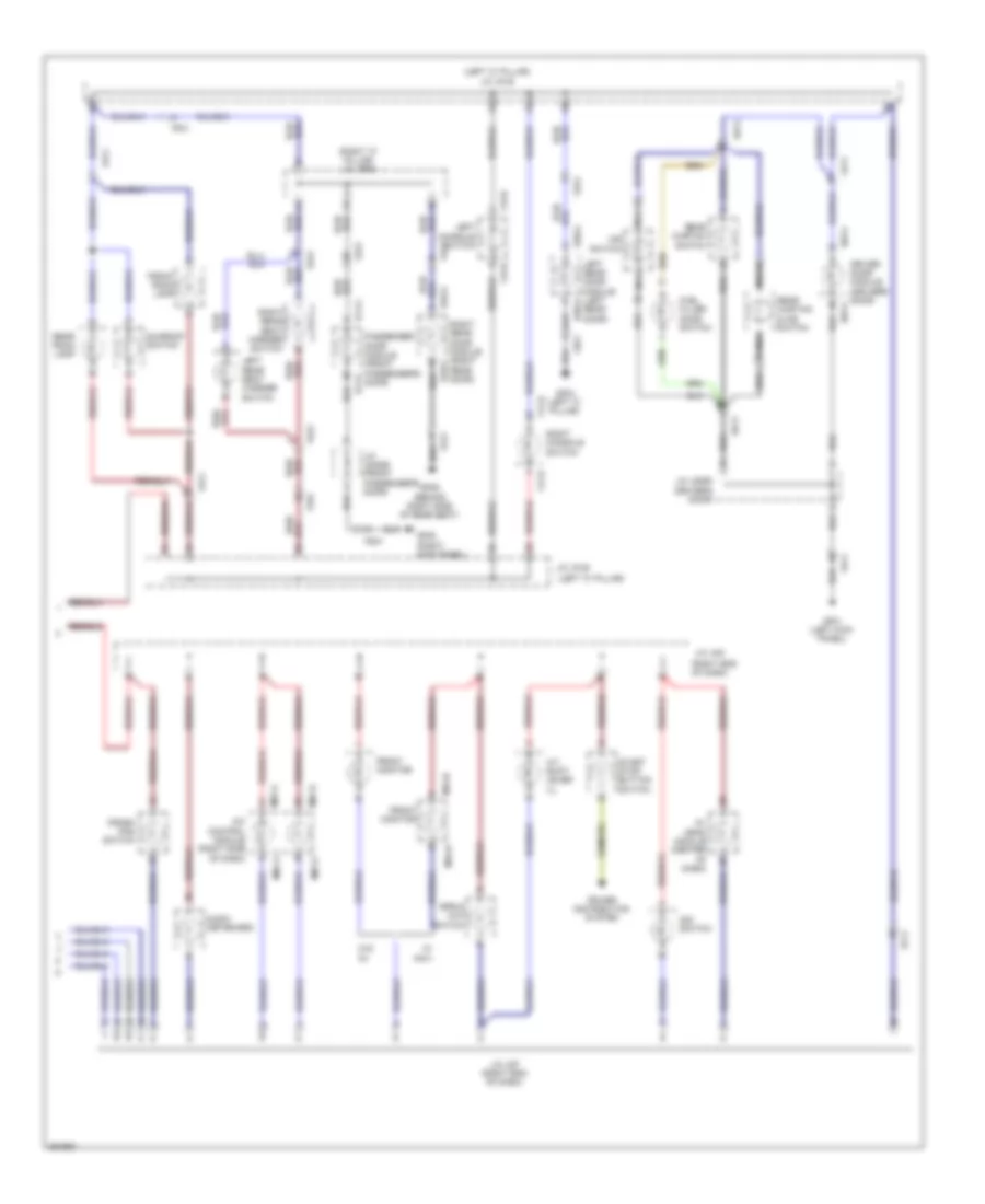
BODY CONTROL MODULES
Front Area Module Wiring Diagram for Hyundai Genesis 5.0 R-Spec 2012
List of elements for Front Area Module Wiring Diagram for Hyundai Genesis 5.0 R-Spec 2012:
- lh turn lp rear
- (left front of
- (left kick panel)
- Anti-theft system
- B-can
- B/a horn
- Computer data lines system
- Connector jeb
- E/r junction box (right rear of engine compt)
- E/r-e1b
- Em21
- Engine compt)
- Ext buzzer
- Exterior lights system
- Fam (front area module)
- Fam 1 (b+) fuse 40a
- Fam 2 (b+) fuse 40a
- Fam-a
- Fam-b
- Fam-c
- Ge03
- Ge04 (lower right rear of engine compt)
- Gm01 (left end of dash)
- Gnd
- Ground
- Headlamp rly ctrl
- Headlights system
- High
- Hood sw
- Hot at all times
- Hot in on or start
- I/p-lhf
- I/p-lhg
- Ill
- Input rain sens
- Interior lights system
- J/c jmd (left side of dash)
- Joint
- Left i/p junction box
- Lh front fog lp
- Lh headlamp hi
- Lh tail lp
- Lh turn lp front
- Lh turn lp side
- Low
- Memory pwr
- Module 1 fuse 10a
- Module 3 fuse 10a
- On/start input
- Output rain sens
- Pnk
- Red
- Rh front fog lp
- Rh headlamp hi
- Rh tail lp
- Rh turn lp front
- Rh turn lp rear
- Rh turn lp side
- Room lp rly ctrl
- Warning systems
- Wiper/washer system
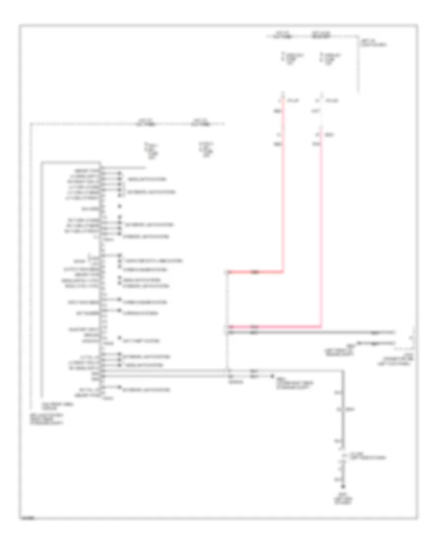
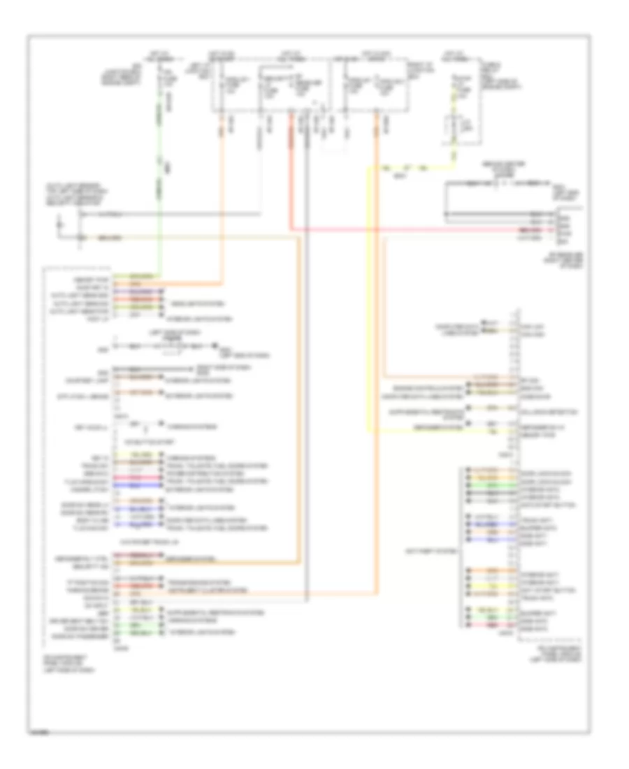
Instrument Panel Module Wiring Diagram for Hyundai Genesis 5.0 R-Spec 2012
List of elements for Instrument Panel Module Wiring Diagram for Hyundai Genesis 5.0 R-Spec 2012:
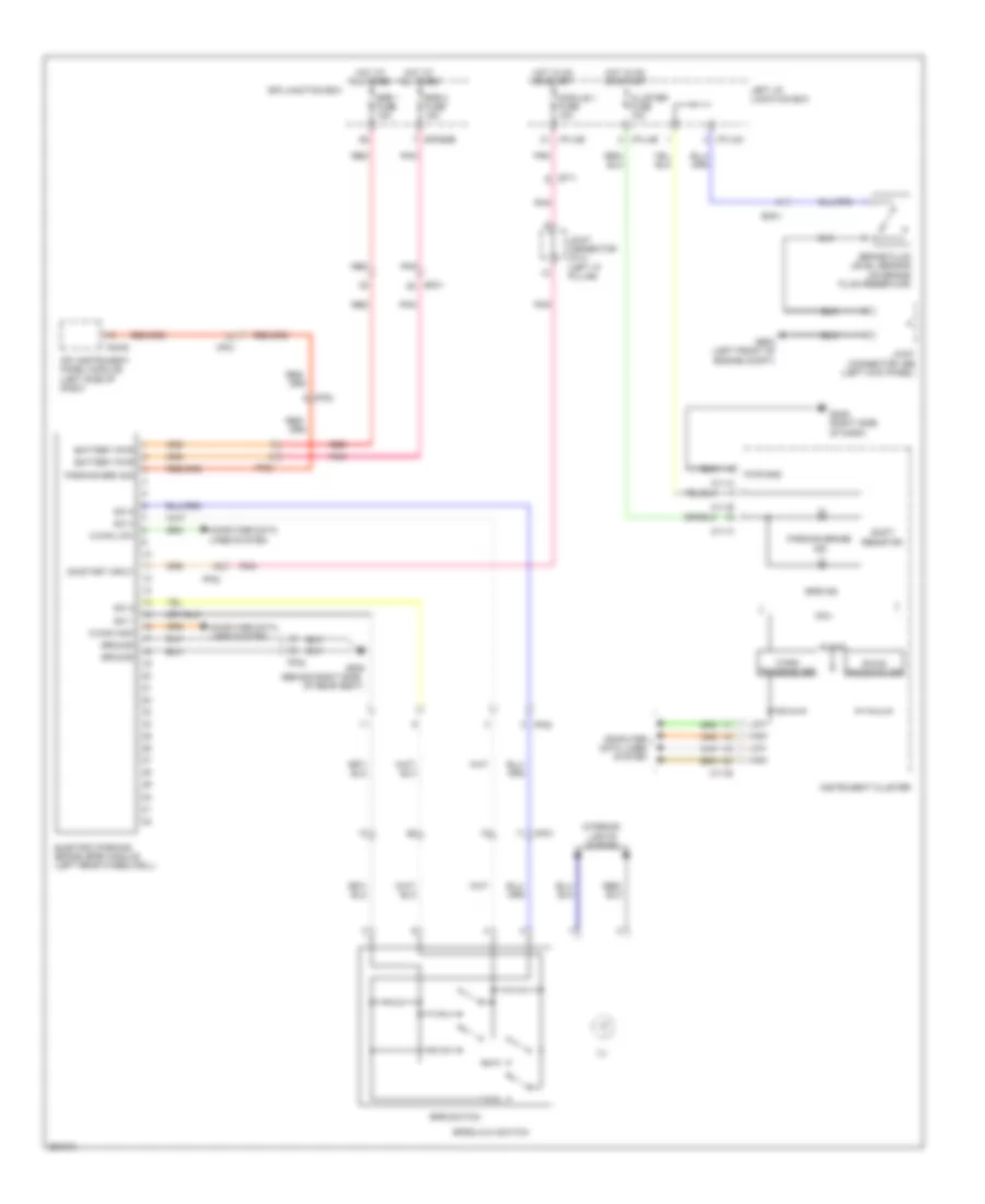
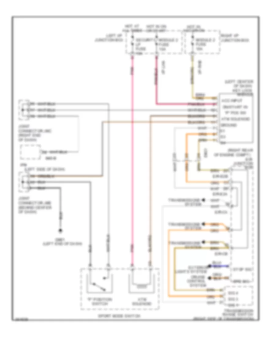
- "p" position sig
- (auto light sensor: top left side of dash) auto light sensor & security indicator
- (behind center of dash) j/c jme
- (left end of dash)
- (left side of dash)
- (right side of dash) gm05
- Acc/on in
- Ant1 start button
- Ant2 start button
- Anti-theft system
- Auto light sens gnd
- Auto light sens pwr
- Auto light sens sig
- Body k-line
- Bumper ant1
- Bumper ant2
- Can high
- Can low
- Code save
- Collision detection
- Computer data lines system
- Courtesy lamp
- Defogger rly ctrl
- Defogger sw in
- Defogger system
- Door lock/unlock
- Door sw driver
- Door sw passenger
- Door sw rear lh
- Door sw rear rh
- Driver seat belt sw
- E/r junction box (right rear of engine compt)
- E/r-e2b
- Em31
- Ems com
- Engine controls system
- Exterior lights system
- Foot lp
- Fuse & relay box (left side of engine compt)
- Gm01
- Gm01 (left end of dash)
- Gnd
- Hazard lp sw
- Headlights system
- Hot at all times
- Hot in acc or on
- Hot in on
- Hot in on or start
- I/p-lha
- I/p-lhd
- I/p-lhg
- I/p-rhd
- Instrument cluster system
- Interior ant1
- Interior ant2
- Interior lights system
- Ipm (instrument panel module)
- Ipm (instrument panel module) (left side of dash)
- Ipm fuse 10a
- J/c jea
- J/c jmd
- Key hole ill
- Key in
- Left i/p junction box
- M40-a
- M40-b
- M40-c
- M40-d
- Memory pwr
- Module 1 fuse 10a
- Module 2 fuse 10a
- On input
- On/start in
- Parking brake
- Pnk
- Power distribution system
- Pwr
- Red
- Rf com
- Rf receiver (right center of dash)
- Rf receiver fuse 10a
- Right i/p junction box
- Sbr
- Security ind
- Security lp fuse 10a
- Side ant1
- Side ant2
- Sig
- Ssb sw-2
- Stop lp fuse 10a
- Stp lp sw l brake
- T/lid handle sw
- T/lid main sw
- Transmissions system
- Trunk ant1
- Trunk ant2
- Trunk sw
- Trunk, tailgate, fuel doors system
- W/o button start
- W/o power trunk lid
- Warning systems
COMPUTER DATA LINES
Computer Data Lines Wiring Diagram (1 of 3) for Hyundai Genesis 5.0 R-Spec 2012
List of elements for Computer Data Lines Wiring Diagram (1 of 3) for Hyundai Genesis 5.0 R-Spec 2012:
- (left "b" pillar) gf02
- (left center of dash) key lock module
- (left end of dash)
- (left front of
- (left side of dash) j/c jmd
- (left side of engine compt)
- (right kick panel)
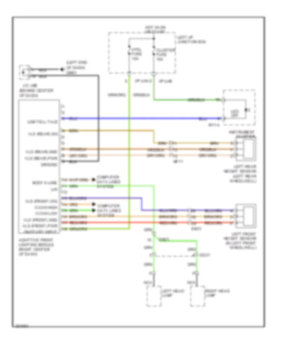
- A01-a
- Active headrest sensor module (under center console)
- Adaptive front lighting module (right center of dash)
- Amp (right side of trunk)
- Auto head lamp leveling device sensor (left rear wheelwell)
- B-can hi
- B-can lo
- C-can hi
- C-can lo
- Camera module (left side of trunk)
- Data link connector (below left side of dash)
- Driver active headrest (in driver's seat back)
- E/r junction box (right rear of engine compt)
- E/r-e2b
- Ef31
- Em31
- Engine compt) esc module
- Esc 1 fuse 30a
- Esc 2 fuse 30a
- Esc fuse 10a
- F03-a
- Fr21
- Fs11
- Fuse & relay box
- Ge02
- Ge02 (right kick panel)
- Gf02 (left "b" pillar)
- Gm01
- Gm05 (right side of dash)
- Hot at all times
- Hot in on or start
- I/p-lha
- Instrument cluster
- J/c jea
- J/c jfrb (right "c" pillar)
- J/c jma (behind center of dash)
- J/c jmc (right end of dash)
- J/c jrb (left front of headliner)
- K-line
- Ldws module (rearview mirror mount)
- Left i/p junction box
- M11-b
- Mf11
- Mf21
- Multipurpose check connector (engine room fuse & relay box)
- Pnk
- Rear curtain module (right side of trunk)
- Red
- Security lp fuse 10a
- Srs control module (under center console)
- Steering angle sensor (on steering column)
- Tire pressure monitoring module (right center of dash)
- Veh spd
Computer Data Lines Wiring Diagram (2 of 3) for Hyundai Genesis 5.0 R-Spec 2012
List of elements for Computer Data Lines Wiring Diagram (2 of 3) for Hyundai Genesis 5.0 R-Spec 2012:
- (front of engine compt)
- (front passenger's door) passenger door module
- (left center of dash)
- (left rear of engine compt)
- (left side of dash)
- (left side of dash) j/c jmcan
- (right side of trunk) forward & rear parking assist control module
- 3.8l/5.0l
- B-can hi
- B-can lo
- Brake vacuum pump (right front of engine compt)
- Code save
- D01-c
- D11-c
- Driver door module (driver's door)
- E/r junction box (right rear of engine compt)
- E/r-e1b
- Ee21
- Ee31
- Ehps module (right front of engine compt)
- Electronic control wiper module
- Em21
- Em31
- F36-a
- Fam
- Fam-b
- Fd11
- Fd21
- Fs11
- Ims control module (under driver's door)
- Ipm (left side of dash)
- J/c jec (right front of engine compt)
- J/c jecan
- J/c jflc (left kick panel)
- M40-c
- M51-b
- M70-a
- Mf11
- Mf21
- Multifunction switch
- Pdm
- Red
- S15-d
- Smart cruise control module (front of engine compt)
- Tilt & telescopic module
Computer Data Lines Wiring Diagram (3 of 3) for Hyundai Genesis 5.0 R-Spec 2012
List of elements for Computer Data Lines Wiring Diagram (3 of 3) for Hyundai Genesis 5.0 R-Spec 2012:
- (4.6l: top of transmission) (5.0l: top rear of engine) j/c jccan
- (left rear of engine compt)
- (left rear of engine compt) engine compt)
- (left rear of engine compt) injector driver box
- (left rear of engine compt) tcm
- (left side of dash)
- (right e/r-e2a
- (right front of trunk)
- (right rear of engine compt) engine room junction box
- 3.8l
- 4.6l
- 4.6l/5.0l
- 5.0l
- A/c control module (right side of dash)
- A/v navigation head unit
- Aa21
- Active accel pedal module (accelerator
- Audio
- Av head module (center of dash)
- B-can hi
- B-can lo
- Box
- C-can hi
- C-can lo
- Clg-idb
- Clg-tg
- Ctg-ag
- Ctg-am
- Ctg-idb
- Ctg-kg
- Ctg-km
- Ctg-tm
- E/r
- E/r junction box (right e/r-e2a rear of engine compt)
- E/r-ca
- E/r-cb
- E/r-e2b
- Ec31
- Ec41
- Ecm
- Electric parking brake module (left rear wheelwell)
- Elg-a
- Ff02
- Front monitor (w/ navi)
- Front monitor (w/o av)
- High
- Injector injector drive box
- Ipm
- J/c jfcan (base of left "b" pillar)
- J/c jfepb
- J/c jfld (left "c" pillar)
- J/c jfrc (right "b" pillar)
- J/c jfrd j/c jfrd (right "c" (right "c" pillar) pillar)
- J/c jmb (behind center
- J/c jmd (left side of dash)
- Junction
- K-line
- Low
- M-can hi
- M-can lo
- M03-a
- M07-a
- M25-a
- M34-b
- M40-b
- M45-a
- Media module (w/ av) (right center of dash)
- Mf11
- Mf31
- Mts module
- Of dash)
- Passenger's seat)
- Pedal bracket)
- Pods module (under front
- Rear of engine compt)
- Red
COOLING FAN
Cooling Fan Wiring Diagram for Hyundai Genesis 5.0 R-Spec 2012
List of elements for Cooling Fan Wiring Diagram for Hyundai Genesis 5.0 R-Spec 2012:
- 3.8l
- 4.6l
- 4.6l & 5.0l
- 5.0l
- A/c comp cut sig
- A/c comp cut sig elg-a
- A/c request sw
- A/c select sw
- Air conditioning system
- Condenser fan
- Cooling fan controller (left front of engine compt)
- Cooling fan fuse 60a
- Cooling fan relay
- Ctg-ag
- Ctg-am
- Ctg-kg
- Ctg-km
- Current detecting
- E/r junction box (right rear of
- E/r-ca
- E/r-cb
- E/r-e2a
- E05-a
- E05-b
- Ec31
- Ec41
- Ecm (left rear of
- Ecu fuse 30a
- Elg-a
- Eng ctrl rly ctrl elg-a
- Engine compt)
- Engine compt) e/r-cb
- Engine control relay
- Engine coolant temperature sensor (3.8l: right rear of engine) (4.6l &5.0l: front of right cylinder head)
- Engine room junction box (right rear
- Fuse & relay box (left side
- Ge01 (left front of engine compt)
- Ge03 (left front of engine compt)
- Glg01
- Gnd
- Hot at all times
- J/c jeb (left kick panel)
- Nca
- Of engine compt)
- Power conditioning
- Pwm to fan mod elg-a
- Pwn driver
- Radiator fan motor
- Signal processing
- Snsr 2 fuse 10a
- Wts sens gnd
- Wts sens sig clg-bg
CRUISE CONTROL
3.8L
3.8L, Cruise Control Wiring Diagram, with SCC for Hyundai Genesis 5.0 R-Spec 2012
List of elements for 3.8L, Cruise Control Wiring Diagram, with SCC for Hyundai Genesis 5.0 R-Spec 2012:
- (+)
- (-)
- (below left
- (left rear of engine compt) ecm (engine control module)
- (lower right rear of engine compt)
- +5v30d
- Amp (right side of trunk)
- Auto head lamp leveling device sensor (left rear wheelwell)
- C-can transceiver
- Camera module (left side of trunk)
- Can- cel
- Ccs power fuse 10a
- Clock spring
- Cluster fuse 10a
- Coast/ set
- Computer data lines system
- Connector
- Cruise ind
- Cruise sw fuse 10a
- Data link
- E/r junction box (right rear of engine compt)
- E/r-e1a
- E/r-e2a
- Ee21
- Elg-a
- Em31
- F03-a
- Ge04
- Gm01 (left end of dash)
- Gnd
- High
- Hot at all times
- Hot in on or start
- I/p-lhc
- I/p-lhe
- I/p-lhf
- I/p-lhg
- Ill
- Instrument cluster
- Interior lights system
- J/c jeb (left kick panel)
- J/c jfrb (right "c" pillar)
- J/c jmc (right end of dash)
- Key lock module (left center of dash)
- Left i/p junction box
- Low
- M/f sw ecu
- M11-a
- M11-b
- Mcu
- Mf21
- Module 1 fuse 10a
- Module 3 fuse 10a
- Multifunction switch
- Nca
- On/ off
- Pnk
- Pwr
- Rear curtain module (right side of trunk)
- Resistor shift
- Resume/ accel
- Right audio & cruise remocon switch
- Scc sensor
- Set ind
- Side of dash)
- Smart cruise control module (front of engine compt)
- Steering wheel
- Stop lamp fuse 10a
- Stop lamp switch (above brake pedal, on bracket)
- Stop lp fuse 10a
- Stop signal relay (left side of dash)
- Tire pressure monitoring module (right center of dash)
3.8L, Cruise Control Wiring Diagram, without SCC for Hyundai Genesis 5.0 R-Spec 2012
List of elements for 3.8L, Cruise Control Wiring Diagram, without SCC for Hyundai Genesis 5.0 R-Spec 2012:
- (+)
- (-)
- +5v30d
- Amp (right side of trunk)
- Aps 1 pwr
- Auto head lamp leveling device sensor (left rear wheelwell)
- Brake lp
- Brake sw
- C-can high
- C-can low
- C-can transceiver
- Camera module (left side of trunk)
- Can- cel
- Clock spring
- Cluster fuse 10a
- Coast/ set
- Computer data lines system
- Cruise ind
- Cruise set ind
- Data link connector (below left side of dash)
- Dis- tant
- E/r junction box (right rear of engine compt)
- E/r-e1a
- E/r-e2a
- Ecm (engine control module) (left rear of engine compt)
- Ecu fuse 30a
- Elg-a
- Em31
- Engine control relay
- Engine control rly control
- Engine control rly on in
- F03-a
- High
- Hot at all times
- Hot in on or start
- I/p-lhe
- I/p-lhf
- I/p-lhg
- Ill
- Instrument cluster
- Interior lights system
- J/c jeb (left kick panel)
- J/c jfrb (right "c" pillar)
- J/c jmc (right end of dash)
- Key lock module (left center of dash)
- Left i/p junction box
- Low
- M11-a
- M11-b
- Mcu
- Mf21
- Module 3 fuse 10a
- Multifunction switch
- Nca
- On/ off
- Rear curtain module (right side of trunk)
- Red
- Resistor shift
- Resume/ accel
- Right audio & cruise remocon switch
- Snsr 3 fuse 10a
- Steering wheel
- Stop lamp fuse 10a
- Stop lamp switch (above brake pedal, on bracket)
- Stop lp fuse 10a
- Stop signal relay (left side of dash)
- Tire pressure monitoring module (right center of dash)
4.6L
4.6L, Cruise Control Wiring Diagram, with SCC (1 of 2) for Hyundai Genesis 5.0 R-Spec 2012
List of elements for 4.6L, Cruise Control Wiring Diagram, with SCC (1 of 2) for Hyundai Genesis 5.0 R-Spec 2012:
- (lower right rear of engine compt)
- (on throttle body)
- 4.6l
- 5.0l
- Accel pedal position sensor (behind accelerator pedal assembly)
- Apm gnd 1
- Apm gnd 2
- Apm pwr 1
- Apm sig 1
- Apm sig 2
- Brake lp
- Brake sw
- C-can high
- C-can low
- Ccs power fuse 10a
- Cluster fuse 10a
- Computer data lines system
- Cruise sw fuse 10a
- Ctg-am
- Ctg-kg
- Ctg-km
- E/r junction box (right rear of engine compt)
- E/r-ca
- E/r-e1a
- E/r-e2a
- Ec31
- Ec41
- Ecm (engine control module) (left rear of engine compt)
- Ee21
- Em31
- Engine room junction box e/r-e2a (right rear of engine compt)
- Etc motor & throttle position sensor (4.6l)
- Etc motor (+)
- Etc motor (-)
- Ge04
- Gnd
- High
- Hot at all times
- Hot in on or start
- I/p-lhc
- I/p-lhe
- I/p-lhf
- I/p-lhg
- J/c jeb (left kick panel)
- Left i/p junction box
- Low
- Module 1 fuse 10a
- Module 3 fuse 10a
- Motor
- Pnk
- Pwr
- Red
- Scc sensor
- Sens pwr
- Sig 1
- Sig 2
- Smart cruise control module (front of engine compt)
- Stop lamp fuse 10a
- Stop lamp switch (above brake pedal, on bracket)
- Stop lp fuse 10a
- Stop signal relay (left side of dash)
- Throttle position sensor
4.6L, Cruise Control Wiring Diagram, with SCC (2 of 2) for Hyundai Genesis 5.0 R-Spec 2012
List of elements for 4.6L, Cruise Control Wiring Diagram, with SCC (2 of 2) for Hyundai Genesis 5.0 R-Spec 2012:
- (+)
- (-)
- (below left side of dash)
- +5v30d
- Amp (right side of trunk)
- Auto head lamp leveling device sensor (left rear wheelwell)
- C-can transceiver
- Camera module (left side of trunk)
- Can- cel
- Clock spring
- Coast/ set
- Computer data lines system
- Cruise ind
- Cruise set ind
- Data link connector
- F03-a
- Gm01 (left end of dash)
- High
- Ill
- Instrument cluster
- Interior lights system
- J/c jfrb (right "c" pillar)
- J/c jmc (right end of dash)
- Key lock module (left center of dash)
- Low
- M/f sw ecu
- M11-a
- M11-b
- Mcu
- Mf21
- Multi- function switch
- Nca
- On/ off
- Rear curtain module (right side of trunk)
- Resistor shift
- Resume/ accel
- Right audio & cruise remocon switch
- Steering wheel
- Tire pressure monitoring module (right center of dash)
4.6L, Cruise Control Wiring Diagram, without SCC (1 of 2) for Hyundai Genesis 5.0 R-Spec 2012
List of elements for 4.6L, Cruise Control Wiring Diagram, without SCC (1 of 2) for Hyundai Genesis 5.0 R-Spec 2012:
- (on throttle body)
- 4.6l
- 5.0l
- Accel pedal position sensor (behind accelerator pedal assembly)
- Acs gnd
- Acs sig
- Apm gnd 1
- Apm gnd 2
- Apm pwr 1
- Apm sig 1
- Apm sig 2
- Brake lp
- Brake sw
- C-can high
- C-can low
- Cluster fuse 10a
- Computer data lines system
- Ctg-ag
- Ctg-am
- Ctg-kg
- Ctg-km
- E/r junction box (right rear of engine compt)
- E/r-ca
- E/r-e1a
- Ec31
- Ec41
- Ecm (engine control module) (left rear of engine compt)
- Ecu fuse 30a
- Em31
- Engine control relay
- Engine control rly control
- Engine control rly on in
- Engine room junction box e/r-e2a (right rear of engine compt)
- Etc motor & throttle position sensor (4.6l)
- Etc motor (+)
- Etc motor (-)
- Gnd
- Hot at all times
- Hot in on or start
- I/p-lhe
- I/p-lhf
- I/p-lhg
- J/c jeb (left kick panel)
- Left i/p junction box
- Module 3 fuse 10a
- Motor
- Pwr
- Red
- Sens pwr
- Sig 1
- Sig 2
- Snsr 1 fuse 10a
- Stop lamp fuse 10a
- Stop lamp switch (above brake pedal, on bracket)
- Stop lp fuse 10a
- Stop signal relay (left side of dash)
- Throttle position sensor
4.6L, Cruise Control Wiring Diagram, without SCC (2 of 2) for Hyundai Genesis 5.0 R-Spec 2012
List of elements for 4.6L, Cruise Control Wiring Diagram, without SCC (2 of 2) for Hyundai Genesis 5.0 R-Spec 2012:
- (+)
- (-)
- +5v30d
- Amp (right side of trunk)
- Auto head lamp leveling device sensor (left rear wheelwell)
- C-can transceiver
- Camera module (left side of trunk)
- Can- cel
- Clock spring
- Coast/ set
- Computer data lines system
- Cruise ind
- Cruise set ind
- Data link connector (below left side of dash)
- Dis- tant
- Em31
- F03-a
- High
- Ill
- Instrument cluster
- Interior lights system
- J/c jfrb (right "c" pillar)
- J/c jmc (right end of dash)
- Key lock module (left center of dash)
- Low
- M11-a
- M11-b
- Mcu
- Mf21
- Multifunction switch
- Nca
- On/ off
- Rear curtain module (right side of trunk)
- Resistor shift
- Resume/ accel
- Right audio & cruise remocon switch
- Steering wheel
- Tire pressure monitoring module (right center of dash)
5.0L
5.0L, Cruise Control Wiring Diagram, with SCC (1 of 2) for Hyundai Genesis 5.0 R-Spec 2012
List of elements for 5.0L, Cruise Control Wiring Diagram, with SCC (1 of 2) for Hyundai Genesis 5.0 R-Spec 2012:
- (lower right rear of engine compt)
- (on throttle body)
- 4.6l
- 5.0l
- Accel pedal position sensor (behind accelerator pedal assembly)
- Apm gnd 1
- Apm gnd 2
- Apm pwr 1
- Apm sig 1
- Apm sig 2
- Brake lp
- Brake sw
- C-can high
- C-can low
- Ccs power fuse 10a
- Cluster fuse 10a
- Computer data lines system
- Cruise sw fuse 10a
- Ctg-am
- Ctg-kg
- Ctg-km
- E/r junction box (right rear of engine compt)
- E/r-ca
- E/r-e1a
- E/r-e2a
- Ec31
- Ec41
- Ecm (engine control module) (left rear of engine compt)
- Ee21
- Em31
- Engine room junction box e/r-e2a (right rear of engine compt)
- Etc motor & throttle position sensor (4.6l)
- Etc motor (+)
- Etc motor (-)
- Ge04
- Gnd
- High
- Hot at all times
- Hot in on or start
- I/p-lhc
- I/p-lhe
- I/p-lhf
- I/p-lhg
- J/c jeb (left kick panel)
- Left i/p junction box
- Low
- Module 1 fuse 10a
- Module 3 fuse 10a
- Motor
- Pnk
- Pwr
- Red
- Scc sensor
- Sens pwr
- Sig 1
- Sig 2
- Smart cruise control module (front of engine compt)
- Stop lamp fuse 10a
- Stop lamp switch (above brake pedal, on bracket)
- Stop lp fuse 10a
- Stop signal relay (left side of dash)
- Throttle position sensor
5.0L, Cruise Control Wiring Diagram, with SCC (2 of 2) for Hyundai Genesis 5.0 R-Spec 2012
List of elements for 5.0L, Cruise Control Wiring Diagram, with SCC (2 of 2) for Hyundai Genesis 5.0 R-Spec 2012:
- (+)
- (-)
- (below left side of dash)
- +5v30d
- Amp (right side of trunk)
- Auto head lamp leveling device sensor (left rear wheelwell)
- C-can transceiver
- Camera module (left side of trunk)
- Can- cel
- Clock spring
- Coast/ set
- Computer data lines system
- Cruise ind
- Cruise set ind
- Data link connector
- F03-a
- Gm01 (left end of dash)
- High
- Ill
- Instrument cluster
- Interior lights system
- J/c jfrb (right "c" pillar)
- J/c jmc (right end of dash)
- Key lock module (left center of dash)
- Low
- M/f sw ecu
- M11-a
- M11-b
- Mcu
- Mf21
- Multi- function switch
- Nca
- On/ off
- Rear curtain module (right side of trunk)
- Resistor shift
- Resume/ accel
- Right audio & cruise remocon switch
- Steering wheel
- Tire pressure monitoring module (right center of dash)
5.0L, Cruise Control Wiring Diagram, without SCC (1 of 2) for Hyundai Genesis 5.0 R-Spec 2012
List of elements for 5.0L, Cruise Control Wiring Diagram, without SCC (1 of 2) for Hyundai Genesis 5.0 R-Spec 2012:
- (on throttle body)
- 4.6l
- 5.0l
- Accel pedal position sensor (behind accelerator pedal assembly)
- Acs gnd
- Acs sig
- Apm gnd 1
- Apm gnd 2
- Apm pwr 1
- Apm sig 1
- Apm sig 2
- Brake lp
- Brake sw
- C-can high
- C-can low
- Cluster fuse 10a
- Computer data lines system
- Ctg-ag
- Ctg-am
- Ctg-kg
- Ctg-km
- E/r junction box (right rear of engine compt)
- E/r-ca
- E/r-e1a
- Ec31
- Ec41
- Ecm (engine control module) (left rear of engine compt)
- Ecu fuse 30a
- Em31
- Engine control relay
- Engine control rly control
- Engine control rly on in
- Engine room junction box e/r-e2a (right rear of engine compt)
- Etc motor & throttle position sensor (4.6l)
- Etc motor (+)
- Etc motor (-)
- Gnd
- Hot at all times
- Hot in on or start
- I/p-lhe
- I/p-lhf
- I/p-lhg
- J/c jeb (left kick panel)
- Left i/p junction box
- Module 3 fuse 10a
- Motor
- Pwr
- Red
- Sens pwr
- Sig 1
- Sig 2
- Snsr 1 fuse 10a
- Stop lamp fuse 10a
- Stop lamp switch (above brake pedal, on bracket)
- Stop lp fuse 10a
- Stop signal relay (left side of dash)
- Throttle position sensor
5.0L, Cruise Control Wiring Diagram, without SCC (2 of 2) for Hyundai Genesis 5.0 R-Spec 2012
List of elements for 5.0L, Cruise Control Wiring Diagram, without SCC (2 of 2) for Hyundai Genesis 5.0 R-Spec 2012:
- (+)
- (-)
- +5v30d
- Amp (right side of trunk)
- Auto head lamp leveling device sensor (left rear wheelwell)
- C-can transceiver
- Camera module (left side of trunk)
- Can- cel
- Clock spring
- Coast/ set
- Computer data lines system
- Cruise ind
- Cruise set ind
- Data link connector (below left side of dash)
- Dis- tant
- Em31
- F03-a
- High
- Ill
- Instrument cluster
- Interior lights system
- J/c jfrb (right "c" pillar)
- J/c jmc (right end of dash)
- Key lock module (left center of dash)
- Low
- M11-a
- M11-b
- Mcu
- Mf21
- Multifunction switch
- Nca
- On/ off
- Rear curtain module (right side of trunk)
- Resistor shift
- Resume/ accel
- Right audio & cruise remocon switch
- Steering wheel
- Tire pressure monitoring module (right center of dash)
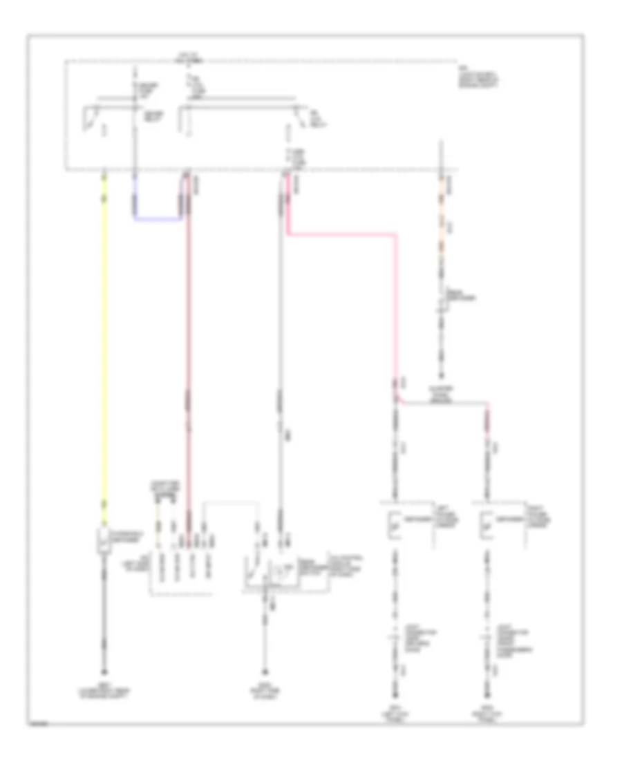
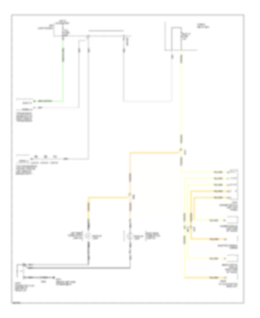
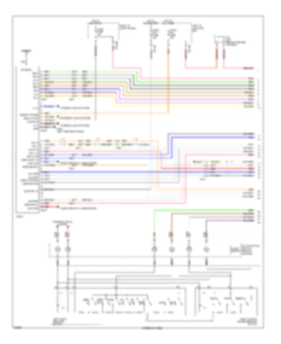
DEFOGGERS
Defoggers Wiring Diagram for Hyundai Genesis 5.0 R-Spec 2012
List of elements for Defoggers Wiring Diagram for Hyundai Genesis 5.0 R-Spec 2012:
- A/c control module (right side of dash)
- B-can high
- B-can low
- Computer data lines system
- Defogger
- Deicer fuse 15a
- Deicer relay
- E/r junction box (right rear of engine compt)
- E/r-e1b
- E/r-e2a
- E/r-e2b
- Ef21
- Em21
- Fd11
- Fd21
- Ge07 (lower right rear of engine compt)
- Gf01 (left kick panel)
- Gf05 (right kick panel)
- Gm02 (right side of dash)
- Hot at all times
- Ind
- Ipm (left side of dash)
- Joint connector jdass (front passenger's door)
- Joint connector jddri (driver's door)
- Left power outside mirror
- M07-a
- M07-d
- M40-b
- M40-c
- Mirr htd fuse 10a
- Nca
- Pnk
- Quarter panel ground
- Rear defogger
- Rear defogger switch
- Right power outside mirror
- Rly ctrl
- Rr htd fuse 40a
- Rr htd relay
- Sw input
- Windshield defogger
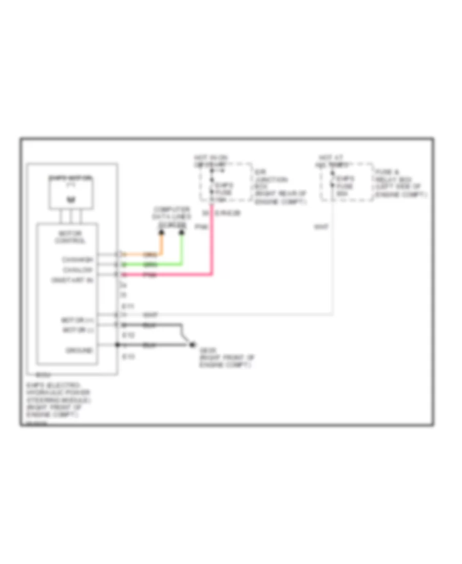
ELECTRONIC POWER STEERING
Electronic Power Steering Wiring Diagram for Hyundai Genesis 5.0 R-Spec 2012
List of elements for Electronic Power Steering Wiring Diagram for Hyundai Genesis 5.0 R-Spec 2012:
- Can-high
- Can-low
- Computer data lines system
- E/r junction box (right rear of
- E/r-e2b
- E11
- E12
- E13
- Ecu
- Ehps (electro- hydraulic power steering module) (right front of engine compt)
- Ehps fuse 10a
- Ehps fuse 80a
- Ehps motor
- Engine compt)
- Fuse & relay box (left side of
- Ge05 (right front of engine compt)
- Ground
- Hot at all times
- Hot in on or start
- Motor (+)
- Motor (-)
- Motor control
- On/start in
- Pnk
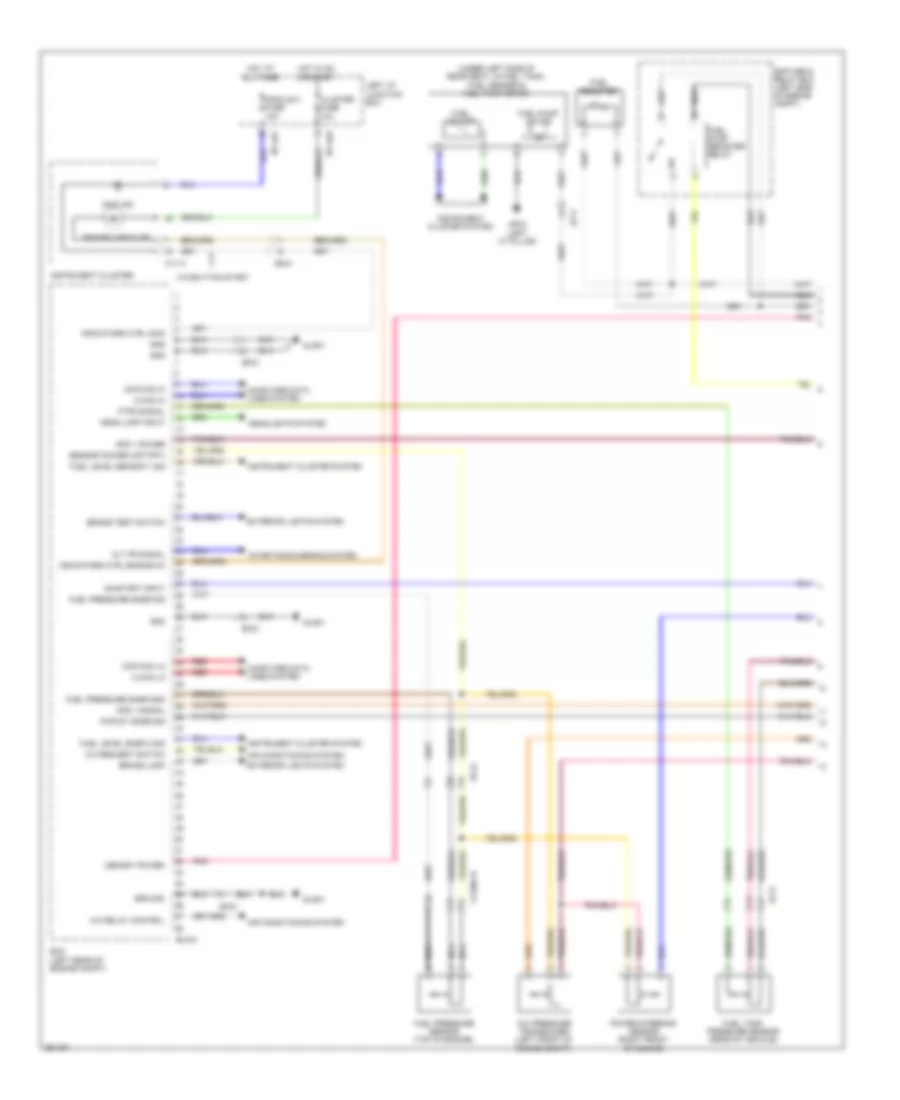
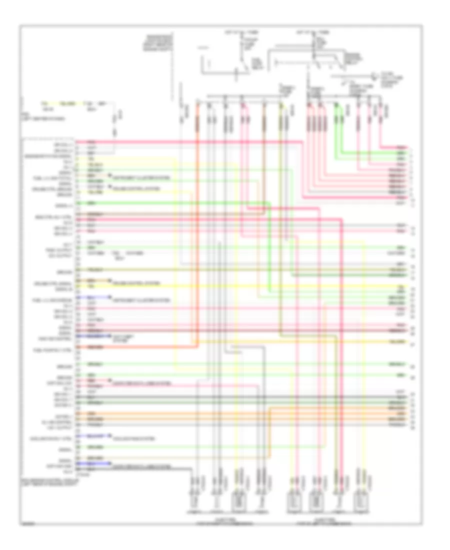
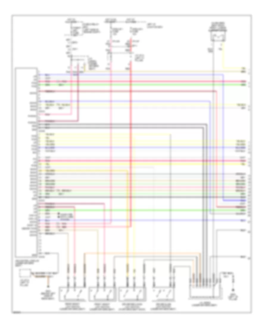
ENGINE PERFORMANCE
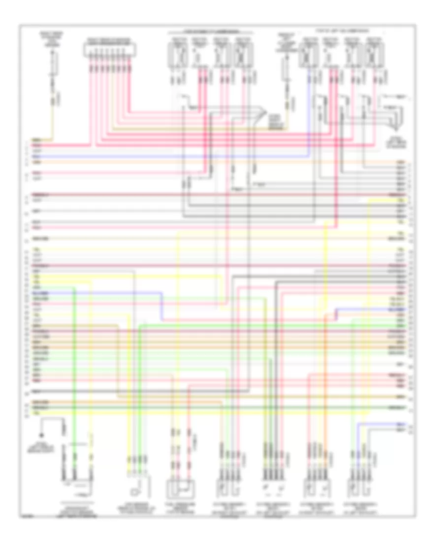
3.8L
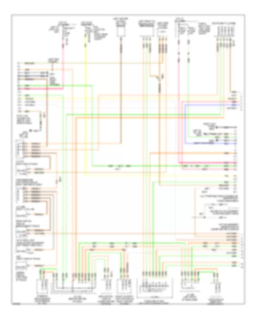
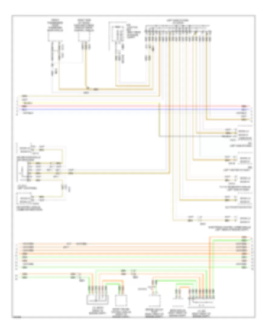
3.8L, Engine Performance Wiring Diagram (1 of 6) for Hyundai Genesis 5.0 R-Spec 2012
List of elements for 3.8L, Engine Performance Wiring Diagram (1 of 6) for Hyundai Genesis 5.0 R-Spec 2012:
- (under left side of rear seat, in fuel tank)
- A/c pressure transducer (left front of engine compt)
- A/c relay control
- A/c request switch
- Air conditioning system
- Alt fr signal
- Aps 1 power
- Aps 1 signal
- Brake lamp
- Brake test switch
- C-can hi
- C-can lo
- Ccp-can hi
- Ccp-can lo
- Clginj-b
- Cluster fuse 10a
- Computer data lines system
- E/r fuse & relay box (left side of engine compt)
- Ec21
- Ecm (left rear of engine compt)
- Ef11
- Elg-a
- Em31
- Engine check ind
- Exterior lights system
- Ftps signal
- Fuel level sensor 1 sig
- Fuel level snsr 2 sig
- Fuel pressure sensor (top of engine)
- Fuel pressure snsr gnd
- Fuel pressure snsr sig
- Fuel pump motor
- Fuel pump register relay
- Fuel register
- Fuel sender
- Fuel sender & fuel pump motor
- Fuel tank pressure sensor (rear of vehicle)
- Gf03 (left "c" pillar)
- Glg01
- Gnd
- Ground
- Head lamp input
- Headlights system
- Hot at all times
- Hot in on or start
- I/p-lhe
- I/p-lhf
- Immo ind
- Indicators ctrl engine ck
- Indicators ctrl immo
- Instrument cluster
- Instrument cluster system
- Left i/p junction box
- M11-a
- Memory power
- Module 3 fuse 10a
- Nca
- On/start input
- Pnk
- Power steering sensor (right front of engine)
- Pwr st snsr sig
- Red
- Sensor power (apt/fpt)
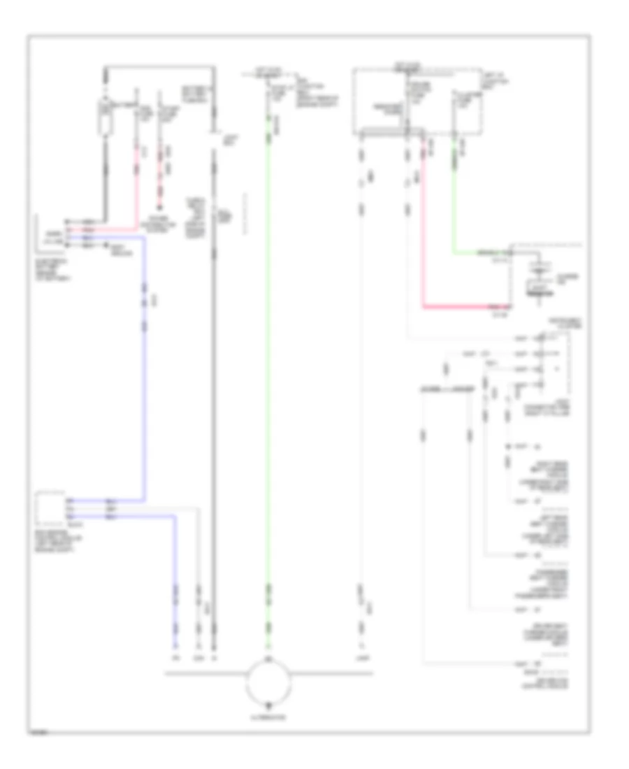
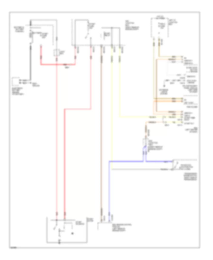
- Starting/charging system
- W/o button start
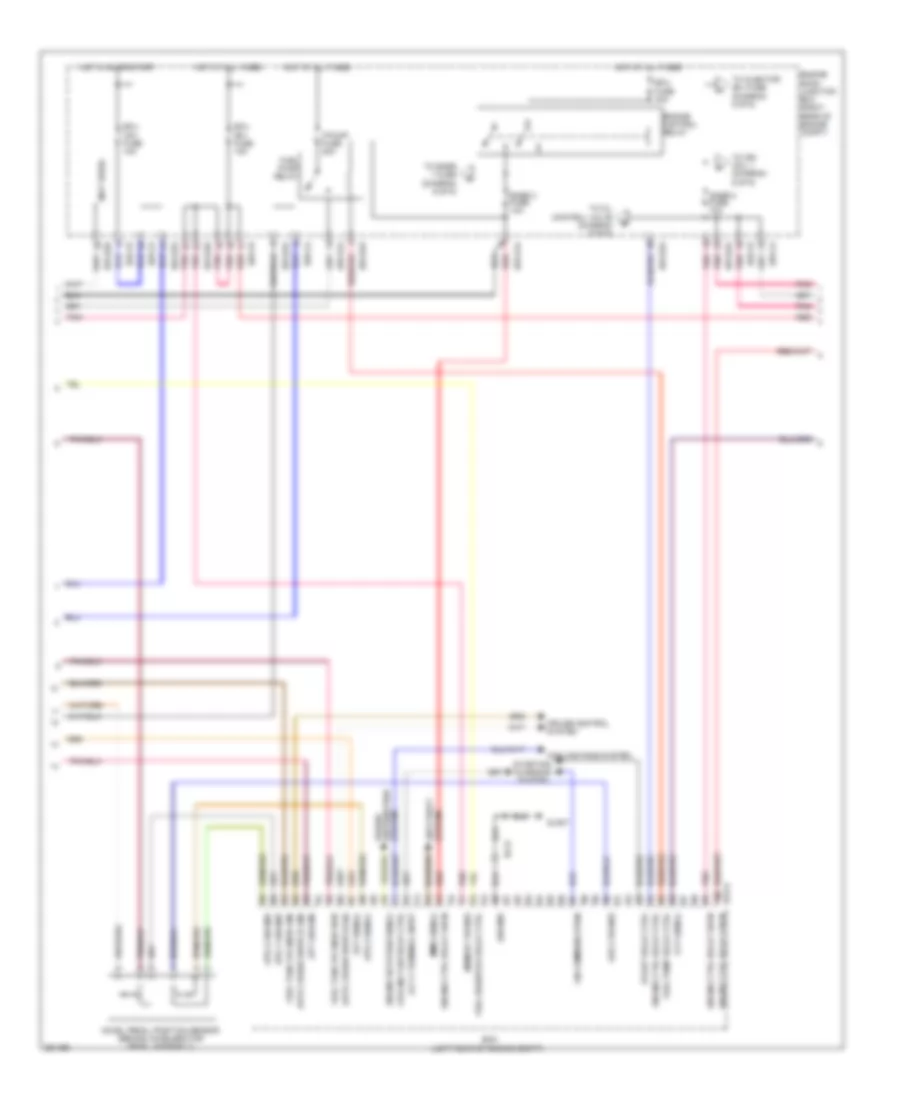
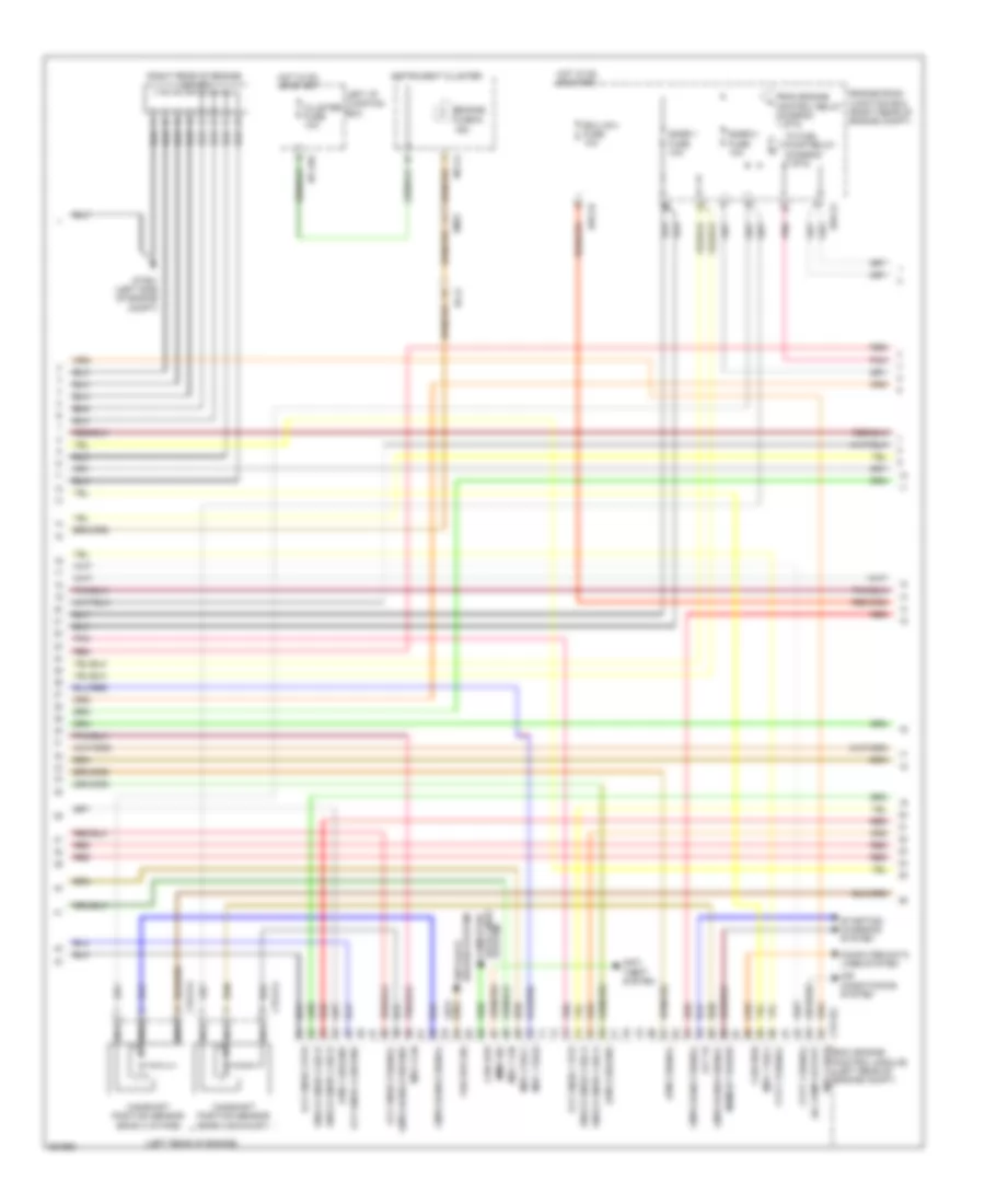
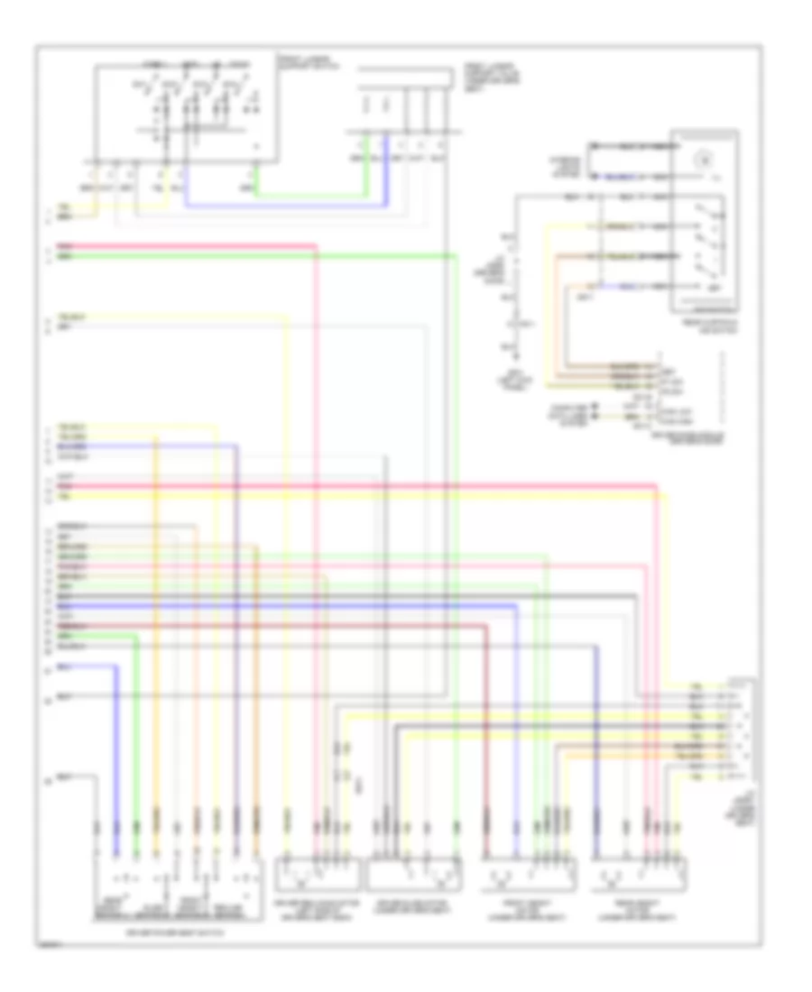
3.8L, Engine Performance Wiring Diagram (2 of 6) for Hyundai Genesis 5.0 R-Spec 2012
List of elements for 3.8L, Engine Performance Wiring Diagram (2 of 6) for Hyundai Genesis 5.0 R-Spec 2012:
- (not used)
- Accel pedal position sensor (behind accelerator pedal assembly)
- Alt c-terminal input
- Anti-theft system
- Aps 1 ground
- Aps 2 ground
- Aps 2 power
- Aps 2 signal
- Apt ground
- Apt signal
- Auto cruise switch gnd
- Auto cruise switch sig
- Ccv signal
- Cooling fan relay ctrl
- Cooling fans system
- Cruise control system
- Distribution system
- E/r-ca
- E/r-cb
- E/r-e1a
- E/r-e2a
- E/r-e2b
- Ec21
- Ecm (left rear of engine compt)
- Ecu (b+) fuse 15a
- Ecu (ig1) fuse 10a
- Ecu fuse 30a
- Elg-a
- Engine control relay
- Engine ctrl relay 'on' in
- Engine ctrl relay ctrl
- Engine room junction box (right rear of engine compt)
- Engine rotation signal
- F/pump fuse 20a
- Fuel pump relay
- Fuel pump relay ctrl
- Fuel resistor relay ctrl
- Fuel tank pr snsr gnd
- Fuel tank pr snsr pwr
- Glg01
- Ground
- Hot at all times
- Hot in on or start
- Immo signal
- Lin communication
- Memory power
- Pnk
- Power
- Red
- Snsr 2 fuse 10a
- Snsr 3 fuse 10a
- Start relay ctrl
- Starting/ charging system
- To ign coil 1 (diagram 6 of 6)
- To injector (b+) fuse (diagram 5 of 6)
- To oil control valve (diagram 6 of 6)
- To snsr 1 fuse (diagram 6 of 6)
3.8L, Engine Performance Wiring Diagram (3 of 6) for Hyundai Genesis 5.0 R-Spec 2012
List of elements for 3.8L, Engine Performance Wiring Diagram (3 of 6) for Hyundai Genesis 5.0 R-Spec 2012:
- (left rear of engine)
- (lower left rear of engine) crankshaft position sensor
- (rear of intake manifold) purge control solenoid valve
- (rear of vehicle) canister close valve
- (right rear of engine)
- (right rear of engine) j/c jca
- (top right rear of engine) oil temperature sensor
- (top right side of engine) variable intake manifold valve
- Camshaft position sensor (bank 1 exhaust)
- Camshaft position sensor (bank 1 intake)
- Camshaft position sensor (bank 2 exhaust)
- Camshaft position sensor (bank 2 intake)
- Clg13-1
- Clg13-2
- Clg13-3
- Clg13-4
- Clg23-1
- Clg23-2
- Ef11
- Knock sensor 1 (top right front of engine)
- Knock sensor 2 (left front of engine)
- Nca
- Pnk
- Red
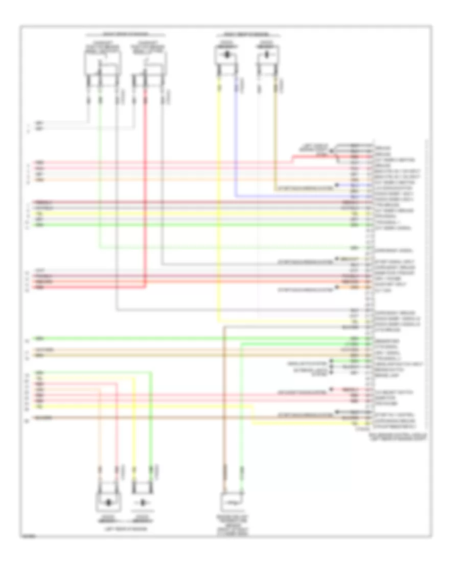
3.8L, Engine Performance Wiring Diagram (4 of 6) for Hyundai Genesis 5.0 R-Spec 2012
List of elements for 3.8L, Engine Performance Wiring Diagram (4 of 6) for Hyundai Genesis 5.0 R-Spec 2012:
- (air filter housing) barometric pressure sensor
- (rear of engine, on intake manifold) map sensor
- (right rear of engine compt) engine room junction box
- (right rear of engine) engine coolant temperature sensor
- (right rear of engine) j/c jca
- Air temp snsr (exhaust)
- Anti-lock brakes system
- Aps 2 signal
- Ckps hi
- Ckps lo
- Clg-bg
- Cmps bank 1 ground
- Cmps bank 2 (exhaust) sig
- Cmps bank 2 ground
- Cmps bank2 (intake) sig
- Cmps power
- Crank request
- E/r-cb
- Ecm (left rear of engine compt)
- Etc motor & throttle position sensor (on throttle body)
- Glg01
- Glg02
- Ground
- Ignition coil 1 control
- Ignition coil 3 control
- Knock sensor 1 hi
- Knock sensor 1 lo
- Knock sensor 2 hi
- Knock sensor 2 lo
- Map signal
- Motor
- Oil temp sensor ground
- Oxygen sensor 1 hi
- Oxygen sensor 1 lo
- Oxygen sensor 4 lo
- Pnk
- Red
- Sensor 1
- Sensor 2
- Sensor power (baro/map)
- Sensor signal
- Shield ground
- Starting/ charging system
- Throttle position sensor
- Tps 1 ground
- Tps 1 power
- Vehicle speed snsr in
- Wts signal
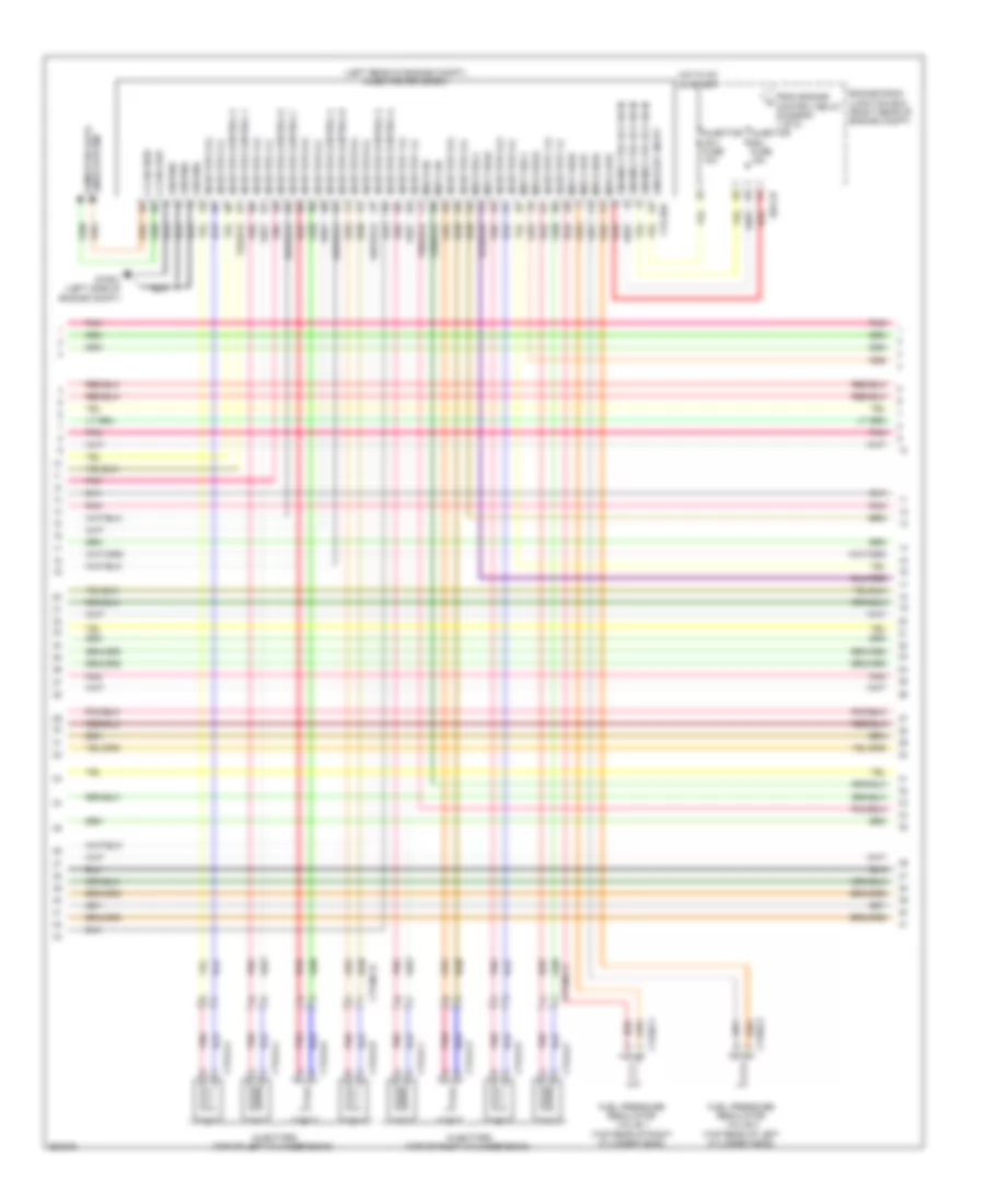
3.8L, Engine Performance Wiring Diagram (5 of 6) for Hyundai Genesis 5.0 R-Spec 2012
List of elements for 3.8L, Engine Performance Wiring Diagram (5 of 6) for Hyundai Genesis 5.0 R-Spec 2012:
- (left rear of engine compt) injector drive box
- (left rear of engine) j/c jcc
- C-can high
- C-can low
- Clg-idb
- Clg05-1
- Clg05-2
- Clg05-3
- Clg05-4
- Clg24-1
- Clg24-2
- Clg24-3
- Clg24-4
- Clg24-5
- Clg24-6
- Clgocv
- Computer data lines system
- Ctginj-b
- Clginj-a
- E/r-cb
- Engine ctrl rly on in
- Engine room junction box (right rear of engine compt)
- From a engine control relay (diagram 2 of 6)
- Glg01
- Ground
- Hot in on or start
- Injector (b+) fuse 15a
- Injector (ig1) fuse 10a
- Injector 1 high
- Injector 1 low
- Injector 2 high
- Injector 2 low
- Injector 3 high
- Injector 3 low
- Injector 4 high
- Injector 4 low
- Injector 5 high
- Injector 5 low
- Injector 6 high
- Injector 6 low
- Injectors (top of left cylinder bank)
- Injectors (top of right cylinder bank)
- Logic input inj1
- Logic input inj2
- Logic input inj3
- Logic input inj4
- Logic input inj5
- Logic input inj6
- Logic input spill valve
- Memory power
- Nca
- Oil control valve 1 (bank 1) (exhaust) (front of right cylinder head)
- Oil control valve 2 (bank 2) (exhaust) (front of left cylinder head)
- Oil control valve 3 (bank 1) (intake) (front of right cylinder head)
- Oil control valve 4 (bank 2) (intake) (front of left cylinder head)
- On/start input
- Pnk
- Red
- Spill valve (top of left cylinder head)
- Spill valve high
- Spill valve low
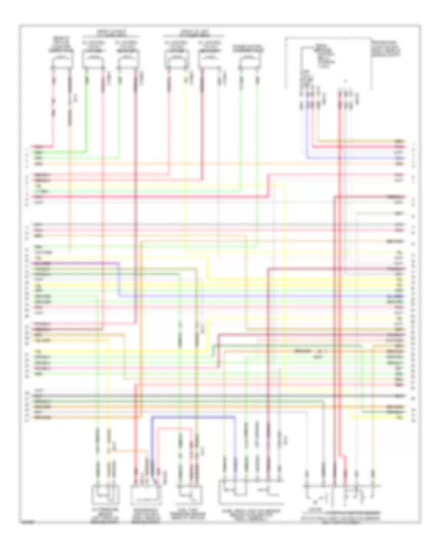
3.8L, Engine Performance Wiring Diagram (6 of 6) for Hyundai Genesis 5.0 R-Spec 2012
List of elements for 3.8L, Engine Performance Wiring Diagram (6 of 6) for Hyundai Genesis 5.0 R-Spec 2012:
- (in left exhaust) oxygen sensor 4 (b2/s2)
- (in right exhaust) oxygen sensor 3 (b1/s2)
- (on left exhaust manifold) oxygen sensor 1 (b1/s1)
- (on right exhaust manifold) oxygen sensor 2 (b2/s1)
- (right
- (top of left cylinder bank)
- (top of right cylinder bank)
- Box
- Clg-bg
- Clg16-1
- Clg16-2
- Clg16-3
- Clg16-4
- Clg18-1
- Clg18-2
- Clg18-3
- Clg18-4
- Clg18-5
- Clg18-6
- Clg19-1
- Clg19-2
- Clgig-1
- Clgig-2
- Cmps bank 1 (intake) sig
- Cmps bank 2 (exhaust) sig
- Cmps bank 2 power
- Condenser (front of left cylinder bank)
- Condenser (top rear of engine)
- Cpsv signal
- Cvvt (exhaust) bank 1
- Cvvt (exhaust) bank 2
- Cvvt (intake) bank 1
- Cvvt (intake) bank 2
- E/r-ca
- E/r-cb
- E/r-e2a
- Engine
- Engine compt)
- Etc motor (hi)
- Etc motor (lo)
- From b snsr 2 fuse (diagram 2 of 6)
- From engine control relay (diagram 2 of 6)
- Glg01
- Glg02
- Ign coil 1 fuse 20a
- Ignition coil 1
- Ignition coil 2
- Ignition coil 2 control
- Ignition coil 3
- Ignition coil 4
- Ignition coil 4 control
- Ignition coil 5
- Ignition coil 5 control
- Ignition coil 6
- Ignition coil 6 control
- Inject0r 1 control
- Inject0r 2 control
- Inject0r 3 control
- Inject0r 4 control
- Inject0r 5 control
- Inject0r 6 control
- J/c jcb (right rear of engine)
- Junction
- Nca
- Oxygen sensor 1 heater
- Oxygen sensor 2 heater
- Oxygen sensor 2 hi
- Oxygen sensor 2 lo
- Oxygen sensor 3 heater
- Oxygen sensor 3 hi
- Oxygen sensor 3 lo
- Oxygen sensor 4 heater
- Oxygen sensor 4 hi
- Pcm (left rear of engine compt)
- Pnk
- Rear of
- Red
- Room
- Sensor ground
- Snsr 1 fuse 10a
- Spill valve control
- Vics signal
4.6L
4.6L, Engine Performance Wiring Diagram (1 of 5) for Hyundai Genesis 5.0 R-Spec 2012
List of elements for 4.6L, Engine Performance Wiring Diagram (1 of 5) for Hyundai Genesis 5.0 R-Spec 2012:
- Anti-theft system
- Ccp can high
- Ccp can low
- Ccv output
- Computer data lines system
- Cooling fan rly ctrl
- Cooling fans system
- Cruise control system
- Cruise ctrl ground
- Cruise ctrl signal
- Ctg-am
- Ctg24-1
- Ctg24-2
- Ctg24-3
- Ctg24-4
- Ctg24-5
- Ctg24-6
- Ctg24-7
- Ctg24-8
- E/r-ca
- E/r-cb
- E/r-e1a
- E/r-e2a
- Ec31
- Ecm (engine control module) (left rear of engine compt)
- Ecu fuse 30a
- Em31
- Eng ctrl rly ctrl
- Engine control relay
- Engine room junction box (right rear of engine compt)
- Engine rotation signal
- F/pump fuse 20a
- Fuel lvl sig (middle)
- Fuel lvl sig (total)
- Fuel pump relay
- Fuel pump rly ctrl
- Ground
- Hot at all times
- Ign coil 1
- Ign coil 2
- Ign coil 3
- Ign coil 4
- Ign coil 5
- Ign coil 6
- Ign coil 7
- Ign coil 8
- Immo ind control
- Inj 1
- Inj 2
- Inj 3
- Inj 4
- Inj 5
- Inj 6
- Inj 7
- Inj 8
- Injectors (top of left cylinder bank)
- Injectors (top of right cylinder bank)
- Instrument cluster system
- M51-b
- Mil ind control
- Motor (+)
- Motor (-)
- Pcsv output
- Pdm (left center of dash)
- Pnk
- Red
- Signal
- Signal a
- Signal b
- Snsr 2 fuse 10a
- Snsr 3 fuse 15a
- To ign coil-1 fuse (diagram 3 of 5)
- To snsr-1 fuse (diagram 4 of 5)
- Vis 1 output
4.6L, Engine Performance Wiring Diagram (2 of 5) for Hyundai Genesis 5.0 R-Spec 2012
List of elements for 4.6L, Engine Performance Wiring Diagram (2 of 5) for Hyundai Genesis 5.0 R-Spec 2012:
- (front of left cylinder head)
- (front of right cylinder head)
- (in air intake duct) mass air flow sensor
- (rear of engine) variable intake manifold valve
- (rear of intake manifold) purge control solenoid valve
- (rear of vehicle) canister close valve
- (under left side of rear seat, in fuel tank)
- A/c pressure sensor (left front of engine compt)
- Accel pedal position sensor (behind accelerator pedal assembly)
- Afm
- Afs
- Ctg05-1
- Ctg05-2
- Ctg05-3
- Ctg05-4
- E/r-ca
- E/r-e2a
- Ec31
- Ef11
- Engine room junction box (right rear of engine compt)
- Etc motor & throttle position sensor (on throttle body)
- Fuel pump motor
- Fuel sender
- Fuel sender & fuel pump motor
- Fuel tank pressure sensor (rear of vehicle)
- Gf03 (left "c" pillar)
- Gtg04 (right side of transmission)
- Instrument cluster system
- Motor
- Oil control valve 1 (intake)
- Oil control valve 2 (exhaust)
- Oil control valve 3 (intake)
- Oil control valve 4 (exhaust)
- Pnk
- Red
- Throttle position sensor
4.6L, Engine Performance Wiring Diagram (3 of 5) for Hyundai Genesis 5.0 R-Spec 2012
List of elements for 4.6L, Engine Performance Wiring Diagram (3 of 5) for Hyundai Genesis 5.0 R-Spec 2012:
- (rear of left cylinder bank) condenser
- (right rear of engine compt) e/r junction box
- (right rear of engine) con- denser
- (right rear of engine) joint connector jcb
- (top of left cylinder bank)
- (top of right cylinder bank)
- 1 of 5)
- Control relay (diagram
- Crankshaft position sensor (left rear of engine)
- Ctg16-1
- Ctg16-2
- Ctg16-3
- Ctg16-4
- Ctg18-1
- Ctg18-2
- Ctg18-3
- Ctg18-4
- Ctg18-5
- Ctg18-6
- Ctg18-7
- Ctg18-8
- Ctg19-1
- Ctg19-2
- E/r-ca
- E/r-cb
- Ecu (b+)
- From engine b
- Fuse 10a
- Gtg02 (right rear of engine)
- Gtg03 (left rear of engine)
- Gtg04 (right side of transmission)
- Hot at all times
- Ign coil 1 fuse 20a
- Ignition coil 1
- Ignition coil 2
- Ignition coil 3
- Ignition coil 4
- Ignition coil 5
- Ignition coil 6
- Ignition coil 7
- Ignition coil 8
- Nca
- Oxygen sensor 1 (b1/s1) (on right exhaust manifold)
- Oxygen sensor 2 (b2/s1) (on left exhaust manifold)
- Oxygen sensor 3 (b1/s2) (in right exhaust)
- Oxygen sensor 4 (b2/s2) (in left exhaust)
- Pnk
- Red
4.6L, Engine Performance Wiring Diagram (4 of 5) for Hyundai Genesis 5.0 R-Spec 2012
List of elements for 4.6L, Engine Performance Wiring Diagram (4 of 5) for Hyundai Genesis 5.0 R-Spec 2012:
- (left rear of engine)
- (right rear of engine) j/c jca
- A/c comp
- Air conditioning system
- Alt fr
- Anti-theft system
- Brakes system anti-lock
- Camshaft position sensor (bank 2 exhaust)
- Camshaft position sensor (bank 2 intake)
- Can high
- Can low
- Check ind
- Cluster fuse 10a
- Computer data lines system
- Ctg-km
- Ctg13-3
- Ctg13-4
- E/r-ca
- E/r-cb
- E/r-e1a
- Ec31
- Ecm (engine control module) (left rear of engine compt)
- Ecu (ig1) fuse 10a
- Em31
- Engine
- Engine room junction box (right rear of engine compt)
- From engine control relay (diagram 1 of 5)
- Ground
- Ground 1
- Ground 2
- Gtg01 (left side of engine compt)
- Heating
- Hot in on or start
- I/p-lhe
- Immo sig
- Instrument cluster
- Left i/p junction box
- M11-a
- Memo pwr
- Nca
- Pnk
- Power
- Red
- Signal
- Signal 2
- Signal a
- Signal b
- Snsr 1 fuse 10a
- Starting/ charging system
- Stop lp fuse 10a
- Veh spd sig
4.6L, Engine Performance Wiring Diagram (5 of 5) for Hyundai Genesis 5.0 R-Spec 2012
List of elements for 4.6L, Engine Performance Wiring Diagram (5 of 5) for Hyundai Genesis 5.0 R-Spec 2012:
- (left rear of engine)
- (left side of engine compt) gtg01
- (right rear of engine)
- A/c select switch
- Air conditioning system
- Alt com
- Brake lamp
- Brake switch
- Camshaft position sensor (bank 1 exhaust)
- Camshaft position sensor (bank 1 intake)
- Close w/ brake
- Ctg-km
- Ctg13-1
- Ctg13-2
- Ctg23-1
- Ctg23-2
- Ctg23-3
- Ctg23-4
- Ec31
- Ecm (engine control module (left rear of engine compt)
- Em31
- Eng ctrl rly on input
- Engine coolant temperature sensor (front of right cylinder head)
- Exterior lights system
- F/pump resister rly
- Ground
- Headlamp switch
- Headlights system
- Heating
- Hot at all times
- I/p-lhg
- J/c jeb (left kick panel)
- Knock sensor 1
- Knock sensor 2
- Knock sensor 3
- Knock sensor 4
- Left i/p junction box
- Lin communication
- Mcu
- Nca
- On/start input
- Open w/ brake
- Pedal depressed
- Pnk
- Power
- Power 1
- Red
- Signal
- Signal 1
- Signal 2
- Signal a
- Signal b
- Start rly control
- Start signal input
- Starting/charging system
- Stop lamp switch (above brake pedal, on bracket)
- Stop lp fuse 10a
- Stop signal relay (left side of dash)
- Wts ground
- Wts signal
5.0L
5.0L, Engine Performance Wiring Diagram (1 of 6) for Hyundai Genesis 5.0 R-Spec 2012
List of elements for 5.0L, Engine Performance Wiring Diagram (1 of 6) for Hyundai Genesis 5.0 R-Spec 2012:
- Anti-theft system
- Apt ground
- Apt signal
- Ccp can high
- Ccp can low
- Ccv output
- Ckps signal a
- Ckps signal b
- Computer data lines system
- Cooling fan rly ctrl
- Cooling fans system
- Cruise control system
- Cruise ctrl ground
- Cruise ctrl signal
- Ctg-ag
- Cvvt 1 (intake) signal
- Cvvt 2 (ex) signal
- E/r-ca
- E/r-cb
- E/r-e1a
- E/r-e2a
- Ec41
- Ecm (engine control module) (left rear of engine compt)
- Ecu fuse 30a
- Ef11
- Eng ctrl rly ctrl
- Engine control relay
- Engine room junction box (right rear of engine compt)
- Engine speed signal
- Etc motor (+)
- Etc motor (-)
- F/pump fuse 20a
- Fps ground
- From snsr 3 fuse (diagram 5 of 6)
- Ftps gnd
- Ftps signal
- Fuel lvl sig (middle)
- Fuel lvl sig (total)
- Fuel pump motor
- Fuel pump relay
- Fuel pump resistor relay
- Fuel pump rly ctrl
- Fuel resistor (right front wheel well)
- Fuel sender
- Fuel sender & fuel pump motor (under left side of rear seat, in fuel tank)
- Fuse & relay box (left side of engine compt)
- Gf03 (left "c" pillar)
- Hot at all times
- Ignition coil 1 ctrl
- Ignition coil 2 ctrl
- Ignition coil 3 ctrl
- Ignition coil 4 ctrl
- Ignition coil 5 ctrl
- Ignition coil 6 ctrl
- Ignition coil 7 ctrl
- Ignition coil 8 ctrl
- Immo ind control
- Injector 1 control
- Injector 2 control
- Injector 3 control
- Injector 4 control
- Injector 5 control
- Injector 6 control
- Injector 7 control
- Injector 8 control
- Instrument cluster system
- Map signal
- Map snsr gnd
- Mil ind control
- Oxygen snsr 1 ground
- Oxygen snsr 1 signal
- Oxygen snsr 2 ground
- Oxygen snsr 2 signal
- Pcsv output
- Pnk
- Power distribution system
- Red
- Snsr 2 fuse 10a
- To ign coil 1 fuse (diagram 3 of 6)
- To injector (b+) fuse (diagram 2 of 6)
- To snsr 3 fuse (diagram 5 of 6)
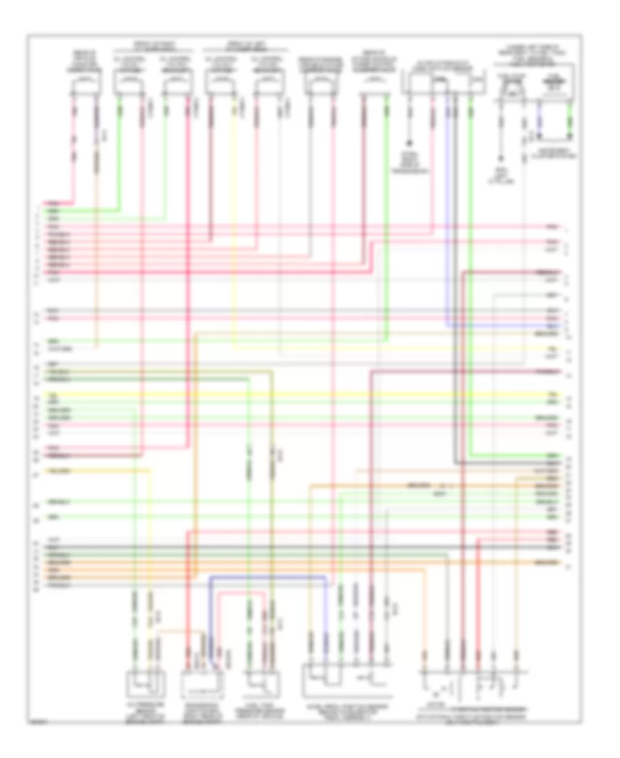
5.0L, Engine Performance Wiring Diagram (2 of 6) for Hyundai Genesis 5.0 R-Spec 2012
List of elements for 5.0L, Engine Performance Wiring Diagram (2 of 6) for Hyundai Genesis 5.0 R-Spec 2012:
- (left rear of engine compt) injector drive box
- C-can high
- C-can low
- Computer data lines system
- Ctg-idb
- Ctg02-1
- Ctg02-2
- Ctg24-1
- Ctg24-2
- Ctg24-3
- Ctg24-4
- Ctg24-5
- Ctg24-6
- Ctg24-7
- Ctg24-8
- Ctginj-a
- Ctginj-b
- E/r-cb
- Engine ctrl rly on in
- Engine room junction box (right rear of engine compt)
- From engine control relay (diagram 1 of 6)
- Fuel pressure regulator valve 1 (top rear of right cylinder head)
- Fuel pressure regulator valve 2 (top rear of left cylinder head)
- Ground
- Gtg01 (left side of engine compt)
- Hot in on or start
- Injector (b+) fuse 15a
- Injector (ig1) fuse 10a
- Injector 1 (+)
- Injector 1 (-)
- Injector 2 (+)
- Injector 2 (-)
- Injector 3 (+)
- Injector 3 (-)
- Injector 4 (+)
- Injector 4 (-)
- Injector 5 (+)
- Injector 5 (-)
- Injector 6 (+)
- Injector 6 (-)
- Injector 7 (+)
- Injector 7 (-)
- Injector 8 (+)
- Injector 8 (-)
- Injector control 1
- Injector control 2
- Injector control 3
- Injector control 4
- Injector control 5
- Injector control 6
- Injector control 7
- Injector control 8
- Injectors (top of left cylinder bank)
- Injectors (top of right cylinder bank)
- Msv1 high
- Msv1 low
- Msv1 on
- Msv1 sel0
- Msv1 sel1
- Msv2 high
- Msv2 low
- Msv2 on
- Msv2 sel0
- Msv2 sel1
- On/start input
- Pnk
- Red
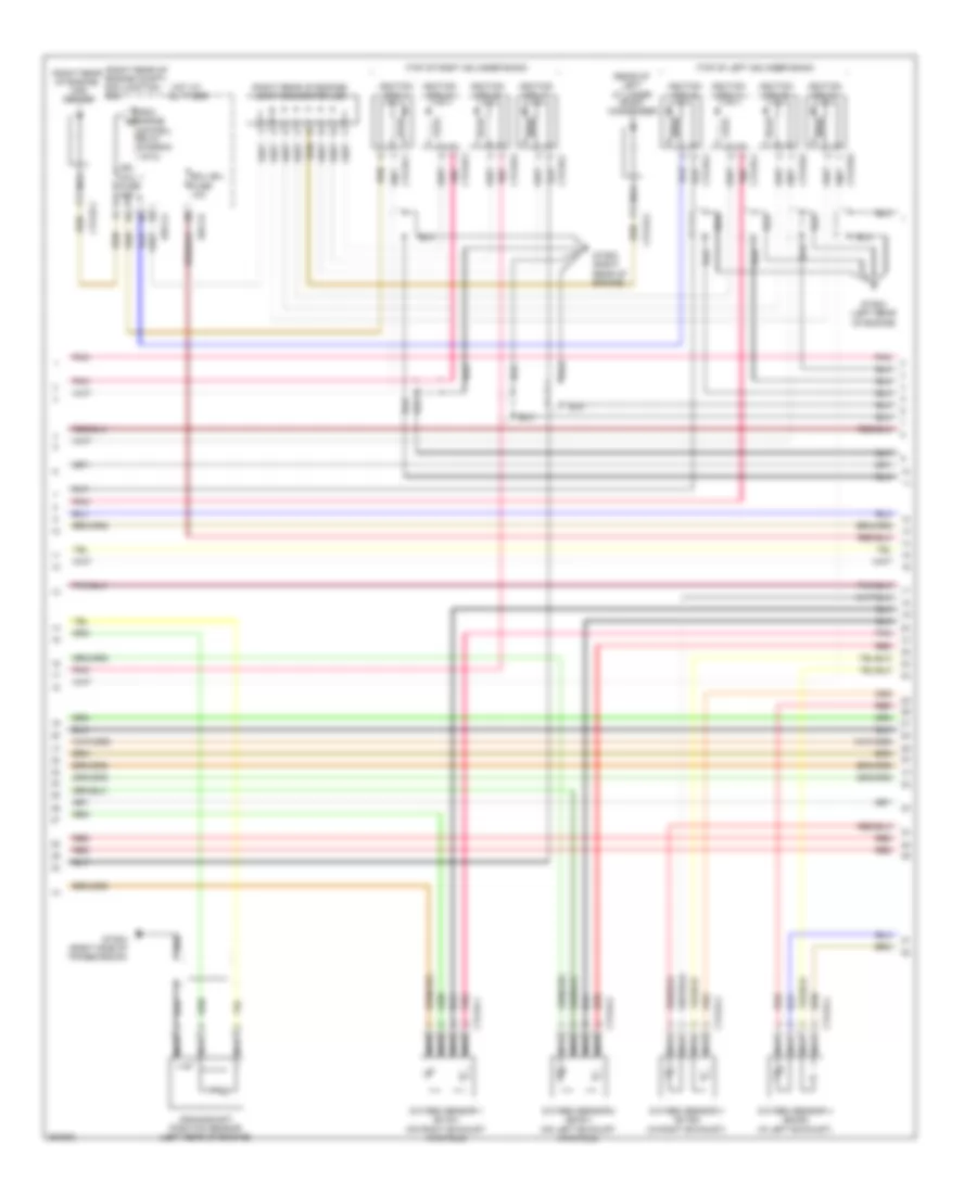
5.0L, Engine Performance Wiring Diagram (3 of 6) for Hyundai Genesis 5.0 R-Spec 2012
List of elements for 5.0L, Engine Performance Wiring Diagram (3 of 6) for Hyundai Genesis 5.0 R-Spec 2012:
- (front of left cylinder head)
- (front of right cylinder head)
- (rear of vehicle) canister close valve
- 1 of 6)
- A/c pressure sensor (left front of engine compt)
- Accel pedal position sensor (behind accelerator pedal assembly)
- Control relay (diagram
- Ctg05-1
- Ctg05-2
- Ctg05-3
- Ctg05-4
- E/r-ca
- E/r-cb
- E/r-e2a
- Ec41
- Ef11
- Engine room junction box (right rear of engine compt)
- Etc motor & throttle position sensor (on throttle body)
- From engine b
- Fuel tank pressure sensor (rear of vehicle)
- Ign coil 1 fuse 20a
- Motor
- Oil control valve 1 (intake)
- Oil control valve 2 (exhaust)
- Oil control valve 3 (intake)
- Oil control valve 4 (exhaust)
- Pnk
- Purge control solenoid valve
- Red
- Throttle position sensor
5.0L, Engine Performance Wiring Diagram (4 of 6) for Hyundai Genesis 5.0 R-Spec 2012
List of elements for 5.0L, Engine Performance Wiring Diagram (4 of 6) for Hyundai Genesis 5.0 R-Spec 2012:
- (rear of left cylinder bank) condenser
- (right rear of engine) con- denser
- (right rear of engine) joint connector jcb
- (top of left cylinder bank)
- (top of right cylinder bank)
- Crankshaft position sensor (left rear of engine)
- Ctg16-1
- Ctg16-2
- Ctg16-3
- Ctg16-4
- Ctg18-1
- Ctg18-2
- Ctg18-3
- Ctg18-4
- Ctg18-5
- Ctg18-6
- Ctg18-7
- Ctg18-8
- Ctg19-1
- Ctg19-2
- Ctginj-a
- Fuel pressure sensor (top of engine)
- Gtg01 (left side of engine compt)
- Gtg02 (right rear of engine)
- Gtg03 (left rear of engine)
- Ignition coil 1
- Ignition coil 2
- Ignition coil 3
- Ignition coil 4
- Ignition coil 5
- Ignition coil 6
- Ignition coil 7
- Ignition coil 8
- Map sensor (rear of engine, on intake manifold)
- Nca
- Oxygen sensor 1 (b1/s1) (on right exhaust manifold)
- Oxygen sensor 2 (b2/s1) (on left exhaust manifold)
- Oxygen sensor 3 (b1/s2) (in right exhaust)
- Oxygen sensor 4 (b2/s2) (in left exhaust)
- Pnk
- Red
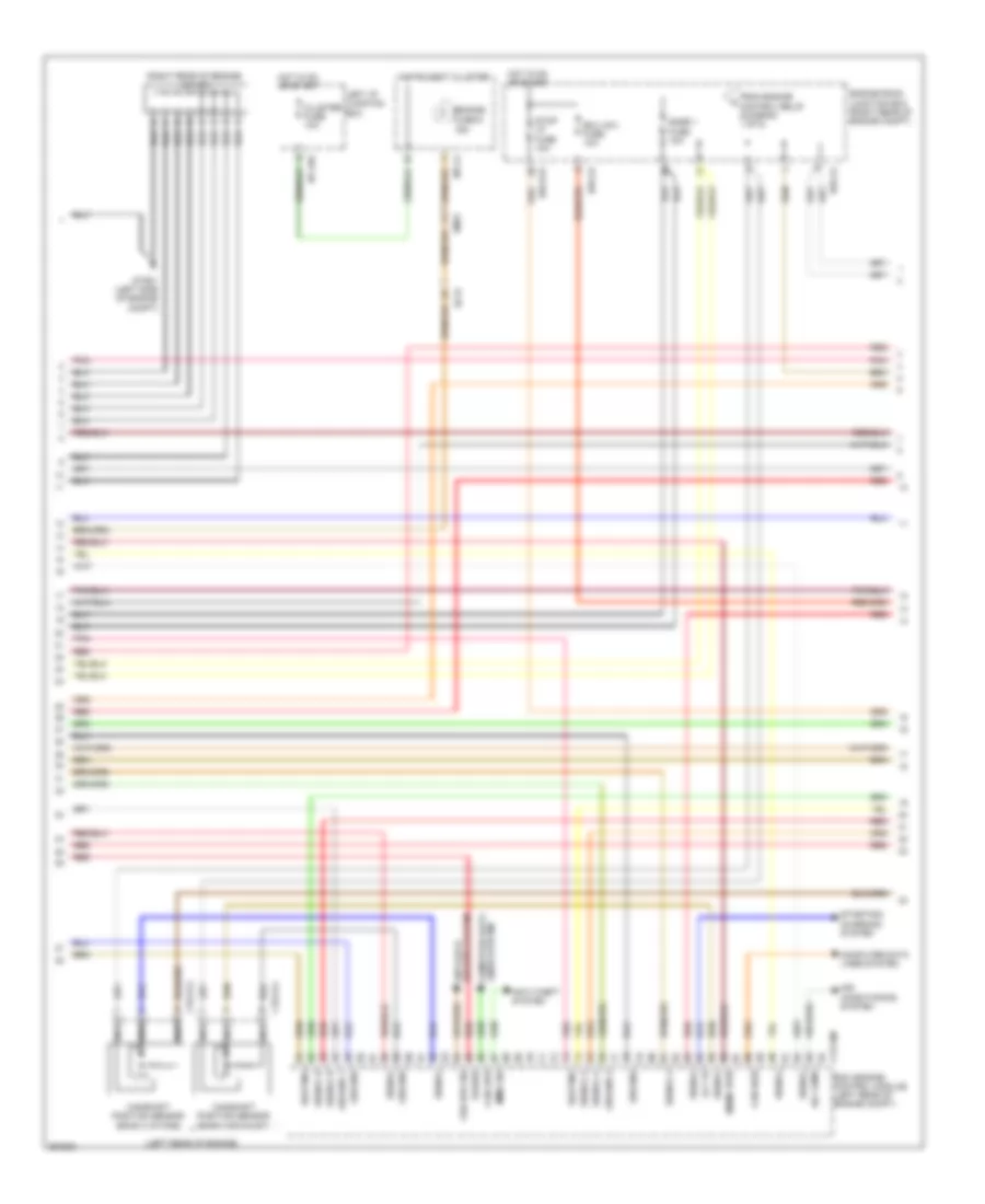
5.0L, Engine Performance Wiring Diagram (5 of 6) for Hyundai Genesis 5.0 R-Spec 2012
List of elements for 5.0L, Engine Performance Wiring Diagram (5 of 6) for Hyundai Genesis 5.0 R-Spec 2012:
- (left rear of engine)
- (right rear of engine) j/c jca
- A/c comp output
- Air conditioning system
- Alt fr
- Anti- theft system
- Apm 1 ground
- Apm 2 ground
- Apm 2 signal
- Brakes system anti-lock
- Camshaft position sensor (bank 2 exhaust)
- Camshaft position sensor (bank 2 intake)
- Can high
- Can low
- Check ind
- Cluster fuse 10a
- Cmps bank1 signal
- Cmps bank2 ground
- Cmps bank2 signal
- Computer data lines system
- Ctg-kg
- Ctg13-3
- Ctg13-4
- Cvvt 3 signal
- Cvvt 4 signal
- E/r-ca
- E/r-cb
- Ec41
- Ecm (engine control module) (left rear of engine compt)
- Ecu (ig1) fuse 10a
- Em31
- Engine
- Engine room junction box (right rear of engine compt)
- From engine control relay (diagram 1 of 6)
- Gtg01 (left side of engine compt)
- Hot in on or start
- I/p-lhe
- Immo sig
- Instrument cluster
- Knock snsr 2 sig a
- Knock snsr 2 sig b
- Knock snsr 4 sig a
- Knock snsr 4 sig b
- Left i/p junction box
- M11-a
- Memory power
- Msv 1 on
- Msv 1 sel0
- Msv 1 sel1
- Msv 2 on
- Msv 2 sel0
- Msv 2 sel1
- Nca
- Oxy snsr 1 htr
- Oxy snsr 3 htr
- Oxy snsr 3 signal
- Oxy snsr 4 ground
- Pnk
- Red
- Snsr 1 fuse 10a
- Snsr 3 fuse 10a
- Starting/ charging system
- To fuel pump relay (diagram 1 of 6)
- Veh spd sig
5.0L, Engine Performance Wiring Diagram (6 of 6) for Hyundai Genesis 5.0 R-Spec 2012
List of elements for 5.0L, Engine Performance Wiring Diagram (6 of 6) for Hyundai Genesis 5.0 R-Spec 2012:
- (left rear of engine)
- (left side of engine compt) gtg01
- (right rear of engine)
- A/c select switch
- Air conditioning system
- Alt com
- Apm 1 power
- Apm 1 signal
- Brake lamp
- Brake switch
- Camshaft position sensor (bank 1 exhaust)
- Camshaft position sensor (bank 1 intake)
- Cmps bank1 ground
- Cmps bank1 signal
- Cmps bank2 ground
- Ctg-kg
- Ctg13-1
- Ctg13-2
- Ctg23-1
- Ctg23-2
- Ctg23-3
- Ctg23-4
- Ecm (engine control module (left rear of engine compt)
- Eng ctrl rly on input
- Engine coolant temperature sensor (front of right cylinder head)
- Exterior lights system
- F/pump resister rly
- Fps power
- Fps signal
- Ground
- Headlamp switch input
- Headlights system
- Knock sensor 1
- Knock sensor 2
- Knock sensor 3
- Knock sensor 4
- Knock snsr 1 sig a
- Knock snsr 1 signal b
- Knock snsr 3 sig a
- Knock snsr 3 signal b
- Lin communication
- Nca
- On/start input
- Oxy snsr 2 heating
- Oxy snsr 3 ground
- Oxy snsr 3 heating
- Oxy snsr 4 signal
- Pnk
- Red
- Sensor gnd
- Snsr pwr
- Snsr pwr (tps/map)
- Start rly control
- Start signal input
- Starting/charging system
- Tps ground
- Tps signal 1
- Tps signal 2
- Wts ground
- Wts signal
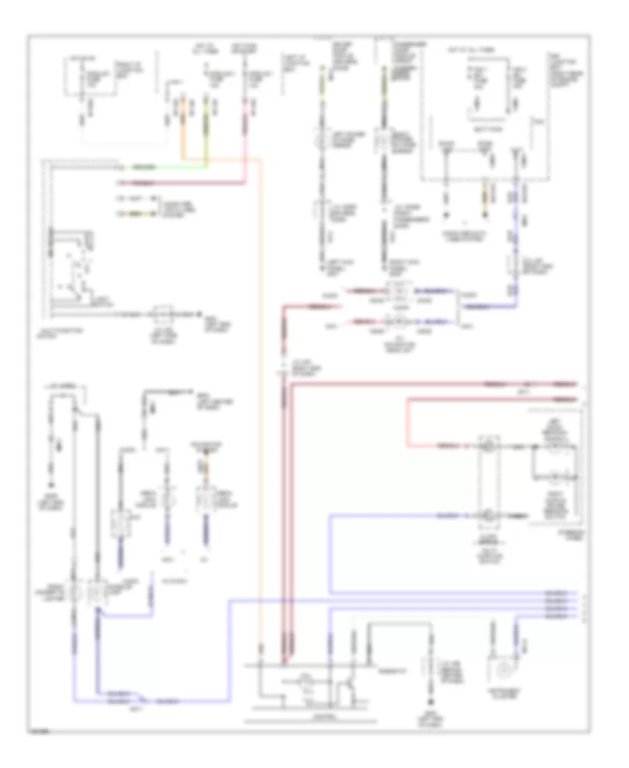
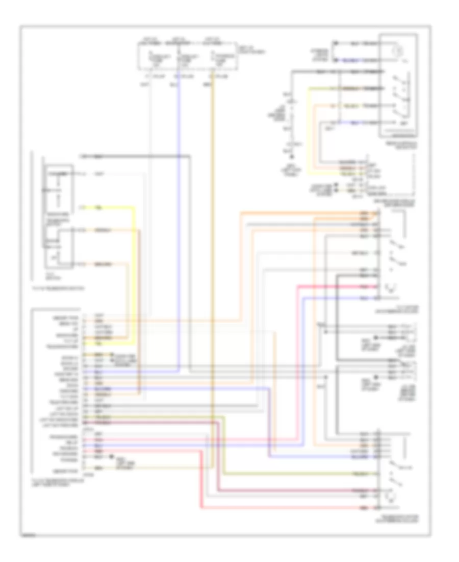
EXTERIOR LIGHTS
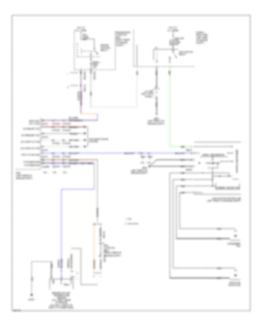
Backup Lamps Wiring Diagram for Hyundai Genesis 5.0 R-Spec 2012
List of elements for Backup Lamps Wiring Diagram for Hyundai Genesis 5.0 R-Spec 2012:
- 3.8l
- 4.6l
- 5.0l
- A/v & navigation head unit
- B/up lp fuse 10a
- Back-up lamp
- Camera module (left side of trunk)
- Clg-tg
- Ctg-tg
- Ctg-tm
- E/r junction box
- E/r-e2b
- Ef21
- Electro chromic mirror
- Fr02
- Fr21
- Fuse & relay box
- Gf10 (behind left side of rear seat)
- Hot in on or start
- Joint connector jflc (left kick panel)
- Joint connector jtlid (center of trunk lid)
- Left rear combination lamp (in)
- M25-e
- Mf11
- Nca
- On/st in
- Rear curtain module (right side of trunk)
- Right rear combination lamp (in)
- Signal 2
- Tcm (transmission control module) (left rear of engine compt)
- Tcu fuse 15a
- Transmission range switch (right side of transmission)
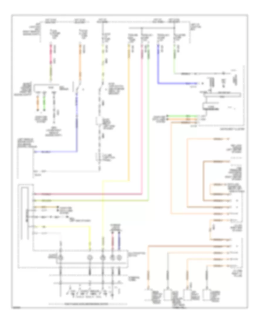
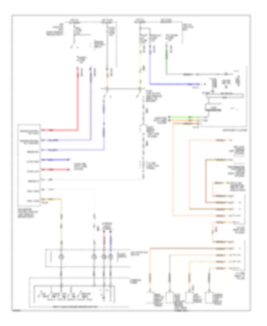
Exterior Lamps Wiring Diagram (1 of 2) for Hyundai Genesis 5.0 R-Spec 2012
List of elements for Exterior Lamps Wiring Diagram (1 of 2) for Hyundai Genesis 5.0 R-Spec 2012:
- (behind center
- (left end
- (left side of dash)
- +5v30d
- 3.8l
- 4.6l
- 5.0l
- A/c control module (right side of dash)
- Auto
- B-can high
- B-can low
- B-can transceiver
- C-can transceiver
- Close w/ brake
- Computer data lines system
- Cruise & epb
- Ctg-kg
- Ctg-km
- E/r junction box (right rear of engine compt)
- E/r-e1a
- Ec31
- Ec41
- Ecm (engine control module) (left rear of engine compt)
- Elg-a
- Em21
- Em31
- Engine compt)
- Esc module (left front of
- Fr02
- Front fog lamp switch
- Fuse & relay box (left side of engine compt)
- Gf10 (behind left side of rear seat)
- Gm01
- Gm01 (left end of dash)
- Gm02 (right side of dash)
- Hazard switch
- Hazard switch m40-b
- Hot at all times
- Hot in on or start
- I/p-lhg
- Ill(+)
- Instrument cluster
- Ipm (instrument panel module) (left side of dash)
- Joint connector jea
- Joint connector jeb (left kick panel)
- Joint connector jmd (left side of dash)
- Joint connector jme
- Joint connector jtlid (center of trunk lid)
- Key lock module (left center of dash)
- Left
- Left i/p junction box
- Left turn ind
- License lamp
- Light switch
- M/f sw ecu
- M07-a
- M07-d
- M11-a
- M11-b
- M40-c
- Mcu
- Mem power
- Multi-function switch
- Nca
- Of dash)
- Off
- Open w/ brake
- Pedal depressed
- Pnk
- Relay
- Right
- Right turn ind
- Signal
- Stop
- Stop lamp relay
- Stop lamp switch (above brake pedal, on bracket)
- Stop lp fuse 10a
- Stop lp s/wl brk m40-a
- Tail on ind
- Trunk lid handle switch
- Trunk lid handle switch & license lamp
- Trunk, tailgate, fuel doors system
- Turn signal lamp switch
- W/ auto
- W/ button start
- W/o auto cruise & epb
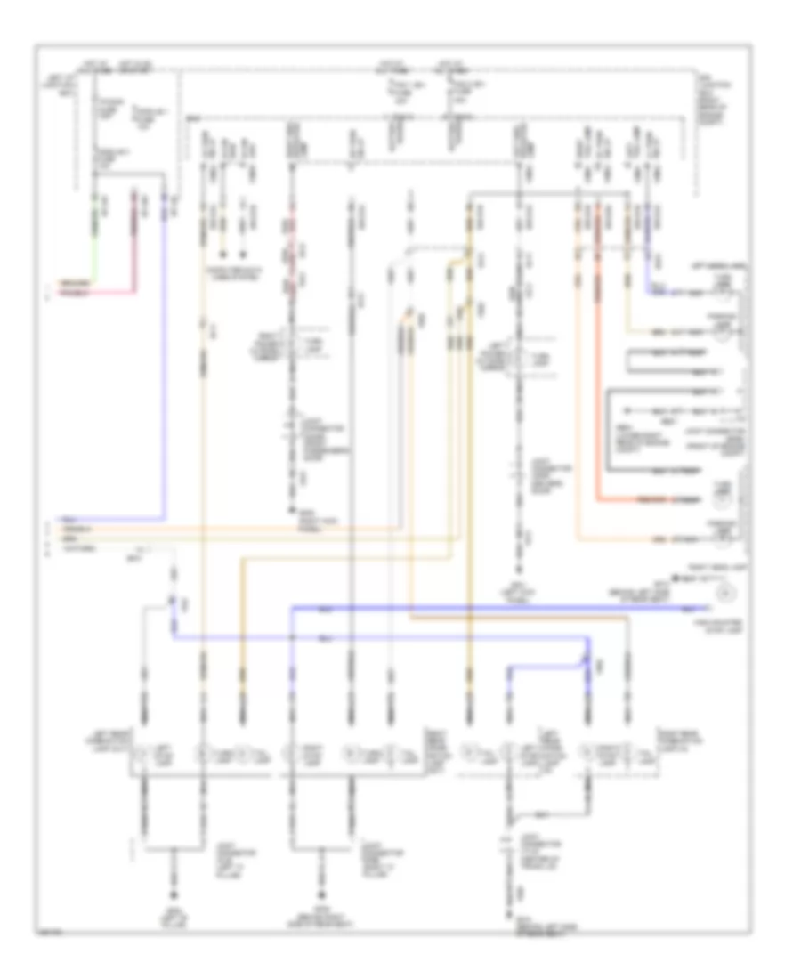
Exterior Lamps Wiring Diagram (2 of 2) for Hyundai Genesis 5.0 R-Spec 2012
List of elements for Exterior Lamps Wiring Diagram (2 of 2) for Hyundai Genesis 5.0 R-Spec 2012:
- (right kick
- 40a
- B-can high
- B-can low fam-b
- Computer data lines system
- E/r junction box (right rear of engine compt)
- E/r-e1a
- E/r-e1b
- E/r-e2a
- Ee21
- Ef11
- Ef21
- Ef31
- Fam
- Fam 1 (b+) fuse
- Fam 2 (b+) fuse
- Fam-a
- Fam-a battery power
- Fam-c
- Fam-c battery power
- Fd11
- Fd21
- Ff01
- Fr02
- Ge04 (lower right rear of engine compt)
- Gf01 (left kick panel)
- Gf02 (left "b" pillar)
- Gf05
- Gf09 (behind right side of rear seat)
- Gf10 (behind left side of rear seat)
- High mounted stop lamp
- Hot at all times
- Hot in on or start
- I/p-lhf
- I/p-lhg
- Joint connector jdass (front passenger's door)
- Joint connector jddri (driver's door)
- Joint connector jefem (front of engine compt)
- Joint connector jflb (left "c" pillar)
- Joint connector jfrb (right "c" pillar)
- Joint connector jtlid (center of trunk lid)
- Lamp fam-a
- Left head lamp
- Left i/p junction box
- Left power outside mirror
- Left rear combi- nation lamp (in)
- Left rear combination lamp (out)
- Left side repeater
- Left stop lamp
- Lr turn sig lp fam-a
- Module 1 fuse 10a
- Module 3 fuse 10a
- Nca
- P/conn fuse 30a
- Panel)
- Parking lamp
- Red/
- Right head lamp
- Right power outside mirror
- Right rear combi- nation lamp (out)
- Right rear combination lamp (in)
- Right side repeater lamp
- Right stop lamp
- Right tail lamp fam-c
- Rr turn sig lp
- Sig lp lf turn
- Sig lp rf turn
- Tail lamp
- Tail lamp left
- Turn lamp
GROUND DISTRIBUTION
Ground Distribution Wiring Diagram (1 of 6) for Hyundai Genesis 5.0 R-Spec 2012
List of elements for Ground Distribution Wiring Diagram (1 of 6) for Hyundai Genesis 5.0 R-Spec 2012:
- (right rear of engine compt) e/r junction box
- A/c control module
- Adaptive front lighting module
- Crash pad switch
- Data link connector
- Door warning switch
- E/r-e1b
- Em21
- Epb & avh switch
- Fam
- Fam-c
- Fet
- Fob holder
- Glove box lamp switch
- Gm01 (left end of dash)
- Gm02 (right side of dash)
- Gm04 (right center of dash)
- Immobilizer module
- Instrument cluster
- Ipm
- Joint connector jmd (left side of dash)
- Joint connector jme (behind center of dash)
- Key lock module
- M07-a
- M07-d
- M11-a
- M40-a
- M40-c
- M45-a
- M51-a
- M70-a
- M70-b
- Media module
- Multifunction switch
- Nca
- Pdm
- Rf receiver
- Rheostat
- Seat belt reminder indicator
- Sport mode switch
- Steering angle sensor
- Steering wheel heater switch
- Stop signal relay
- Telescopic motor
- Tilt & telescopic module
- Tilt & telescopic switch
- Tilt motor
- Tire pressure monitoring module
- W/ av
- W/o button start
Ground Distribution Wiring Diagram (2 of 6) for Hyundai Genesis 5.0 R-Spec 2012
List of elements for Ground Distribution Wiring Diagram (2 of 6) for Hyundai Genesis 5.0 R-Spec 2012:
- A/v & navigation head unit
- Audio
- Aux
- Av head module
- Console lamp
- Console vent temperature actuator & switch
- Cooling fan controller
- D11-a
- D11-c
- Data link connector
- E05-b
- Esc module
- Fd21
- Front cigarette lighter
- Front monitor
- Front power outlet
- Fuse & relay box
- Ge01 (left front of engine compt)
- Ge02 (right kick panel)
- Gf05 (right kick panel)
- Gm03 (left center of dash)
- Gm05 (right side of dash)
- Gm06 (left end of dash)
- Instrument cluster
- Ipm
- Joint connector jdass (front passenger's door)
- Joint connector jmsex
- M03-e
- M11-a
- M25-e
- M34-b
- M40-a
- Media jack module
- Mf11
- Mf21
- Mm11
- Mts module
- Multipurpose check connector
- Navigation
- Nca
- Passenger door lock actuator
- Passenger door module
- Passenger power window module
- Right front smart outside handle
- Right power outside mirror
- Steering wheel heater
- W/ av
- W/o av navigation
Ground Distribution Wiring Diagram (3 of 6) for Hyundai Genesis 5.0 R-Spec 2012
List of elements for Ground Distribution Wiring Diagram (3 of 6) for Hyundai Genesis 5.0 R-Spec 2012:
- (right rear of engine compt) e/r junction box
- 3.8l
- Acc socket relay
- Active accel pedal module
- Aqs sensor
- Auto head lamp leveling device sensor
- Blower relay
- Brake fluid level sensor
- Brake vacuum pump
- Brake vacuum pump relay
- Burglar alarm horn
- Cooling fan relay
- E/r-e1b
- E/r-e2b
- Ee21
- Ee31
- Ef31
- Ehps motor
- Ehps noise
- Electronic control wiper module
- Escl (acc) relay
- Escl (ign1) relay
- Escl (ign2) relay
- External buzzer
- Fam
- Fam-b
- Fam-c
- Fuse & relay box
- Ge03 (left front of engine compt)
- Ge04 (lower right rear of engine compt)
- Ge05 (right front of engine compt)
- Ge06 (left front of engine compt)
- Ge07 (lower right rear of engine compt)
- Hood switch
- J/c jefem (front of engine compt)
- Joint connector jeb (left kick panel)
- Left front fog lamp
- Left head lamp
- Left horn
- Nca
- Right front fog lamp
- Right head lamp
- Right horn
- Smart cruise control module
- Washer level sensor
- Washer motor
- Windshield defogger
Ground Distribution Wiring Diagram (4 of 6) for Hyundai Genesis 5.0 R-Spec 2012
List of elements for Ground Distribution Wiring Diagram (4 of 6) for Hyundai Genesis 5.0 R-Spec 2012:
- (not used)
- Camera module
- D01-a
- D01-c
- D11-c
- D39-a
- Dd11
- Driver door lock actuator
- Driver door module
- Electro chromic mirror
- F36-a
- Fd11
- Fd21
- Fd31
- Fd41
- Ff01
- Forward & rear parking assist control module
- Fr11
- Front room lamp
- Fs11
- Fs41
- Fuel filler door motor
- Fuel filler door switch
- Fuel sender & fuel pump motor
- Gf01 (left kick panel)
- Gf02 (left "b" pillar)
- Gf03 (left "c" pillar)
- Gf04 (behind left side of rear seat)
- Ims control module
- Ims switch
- Joint connector jddri (driver's door)
- Joint connector jfla (left "c" pillar)
- Joint connector jflb (left "c" pillar)
- Joint connector jra (left front of headliner)
- Ldws module
- Left front smart outside handle
- Left power outside mirror
- Left rear combination lamp
- Left rear door lock actuator
- Left rear door module
- Left rear seat warmer module
- Left vanity lamp
- Navi
- Nca
- Overhead console lamp
- Passenger door module
- Rear curtain & ims switch
- Rear curtain module
- Rear curtain switch
- Rear room lamp
- Right rear seat warmer module
- Right vanity lamp
- S15-d
- Sunroof switch
Ground Distribution Wiring Diagram (5 of 6) for Hyundai Genesis 5.0 R-Spec 2012
List of elements for Ground Distribution Wiring Diagram (5 of 6) for Hyundai Genesis 5.0 R-Spec 2012:
- (behind right side of rear seat)
- (under center console)
- A01-a
- Aa11
- Aa21
- Amp
- Av jbl amp
- Belt tension sensor
- D39-a
- D49-a
- Data link connector
- Driver active headrest
- Driver ccs control module
- Driver power seat switch
- Driver reclining limit switch
- Driver seat buckle switch
- Driver seat warmer module
- Driver slide limit switch
- Ef31
- Electric parking brake module
- F03-a
- F08-a
- F36-a
- Fd31
- Fd41
- Ff02
- Forward & rear parking assist control module
- Fr21
- Front height limit switch
- Fs11
- Fs21
- Fs41
- Fuse & relay box
- Ga01
- Gf02 (left "b" pillar)
- Gf06 (right "b" pillar)
- Gf07 (right "c" pillar)
- Gf08 (behind right side of rear seat)
- Gf09
- Ims control module
- Joint connector jfrb (right "c" pillar)
- Joint connector jsass (under front passenger's seat)
- Joint connector jsdri2 (under driver's seat)
- Joint connector jsrr (under rear seat)
- Left rear door module
- Mf11
- Multipurpose check connector
- Nca
- Not used
- Passenger active headrest
- Passenger power seat relay box
- Passenger power seat switch
- Passenger seat warmer module
- Pods module
- Rain sensor
- Rear curtain module
- Rear height limit switch
- Right rear combination lamp (out)
- Right rear door lock actuator
- Right rear door module
- Right rear seat warmer module
- S03-a
- S15-b
- Srs control module
- W/o ccs
Ground Distribution Wiring Diagram (6 of 6) for Hyundai Genesis 5.0 R-Spec 2012
List of elements for Ground Distribution Wiring Diagram (6 of 6) for Hyundai Genesis 5.0 R-Spec 2012:
- (4.6l) (right side of transmission)
- (5.0l) crankshaft position sensor shield
- (5.0l) injector drive box
- 3.8l
- 4.6l
- 5.0l
- Clg-idb
- Clg-tg
- Clg-tm
- Clg19-1
- Clg19-2
- Condenser
- Crankshaft position sensor shield
- Ctg-kg
- Ctg-km
- Ec21
- Ecm
- Elg-a
- Engine coolant temperature sensor
- Fr02
- Gf10 (behind left side of rear seat)
- Glg01
- Glg02
- Gtg01 (left side of engine compt)
- Gtg02 (right rear of engine)
- Gtg03 (left rear of engine)
- Gtg04
- High- mounted stop lamp
- Ignition coil 1 shield
- Ignition coil 1,3,5 shield
- Ignition coil 2 shield
- Ignition coil 2,4,6 shield
- Ignition coil 3 shield
- Ignition coil 4 shield
- Ignition coil 5 shield
- Ignition coil 6 shield
- Ignition coil 7 shield
- Ignition coil 8 shield
- Injector drive box
- Joint connector jca (right rear of engine)
- Joint connector jcb (right rear of engine)
- Joint connector jtlid (center of trunk lid)
- Left rear combination lamp (in)
- Mass air flow sensor
- Nca
- Power latch assembly
- Right rear combination lamp (in)
- Tcm
- Throttle position sensor shield
- Trunk lid handle switch & license lamp
HEADLIGHTS
Adaptive Front Lighting Wiring Diagram for Hyundai Genesis 5.0 R-Spec 2012
List of elements for Adaptive Front Lighting Wiring Diagram for Hyundai Genesis 5.0 R-Spec 2012:
- (behind center
- (left end
- (left rear wheelwell)
- Adaptive front lighting module (right center of dash)
- Afsl fuse 10a
- Body k-line
- C-can high
- C-can low
- Cluster fuse 10a
- Computer data lines system
- Ee21
- Em21
- Em31
- Gm01
- Ground
- Hot in on or start
- I/p-lha
- I/p-lhe
- Instrument cluster
- J/c jme
- Ldm tell tale
- Led off
- Left front height sensor (in left front wheelwell)
- Left head lamp
- Left i/p junction box
- Left rear height sensor
- Lin
- M11-a
- Mf11
- Nca
- Of dash)
- On/start input
- Right head lamp
- Vls (front) gnd
- Vls (front) pwr
- Vls (front) sig
- Vls (rear) gnd
- Vls (rear) pwr
- Vls (rear) sig
Headlamps Wiring Diagram for Hyundai Genesis 5.0 R-Spec 2012
List of elements for Headlamps Wiring Diagram for Hyundai Genesis 5.0 R-Spec 2012:
- (5.0l)
- 3.8l
- 4.6l/ 5.0l
- Auto
- Auto head lamp leveling device sensor (left rear wheelwell)
- Auto light sensor
- Auto light sensor & security indicator (top left side of dash)
- Batt pwr
- Can high
- Can low
- Cluster fuse 10a
- Computer data lines system
- Ctg-kg
- Ctg-km (4.6l)
- Dim
- Dimmer/ passing switch
- E/r junction box (right rear of engine compt)
- E/r-cb
- E/r-e1a
- E/r-e1b
- E/r-e2a
- E/r-e2b
- Ecm (left rear of engine compt)
- Ee21
- Ee31
- Ef21
- Elg-a
- Fam
- Fam 1 (b+) fuse 40a
- Fam 2 (b+) fuse 40a
- Fam-a
- Fam-b
- Fam-c
- Front fog ind
- Front fog lamp switch
- Ge03 (left front of engine compt)
- Ge04 (lower right rear of engine compt)
- Ge06 (left front of engine compt)
- Ge07 (lower right rear of engine compt)
- Gm01 (left end of dash)
- Head lamp relay
- Head lamp relay ctrl
- High beam ind
- Hot at all times
- Hot in on or start
- I/p-lhe
- I/p-lhf
- I/p-lhg
- Instrument cluster
- Ipm (instrument panel module) (left side of dash)
- Ipm fuse 10a
- J/c jefem (front of engine compt)
- J/c jmd (left side of dash)
- Left front fog lamp
- Left h/lp low fuse 15a
- Left headlamp
- Left i/p junction box
- Lh front fog lamp
- Lh head lamp hi
- Light switch
- M/f sw ecu
- M11-a
- M11-b
- M40-a
- M40-c
- Mcu
- Module 1 fuse 10a
- Module 3 fuse 10a
- Multifunction switch
- Nca
- Off
- P/conn fuse 30a
- Pass
- Pnk
- Red
- Rh front fog lamp
- Rh head lamp hi
- Right front fog lamp
- Right h/lp low fuse 15a
- Right headlamp
- Sens gnd
- Sens pwr
- Sens sig
- Shift resistor
- Transceiver b-can
- Transceiver c-can
- W/o hid
Headlamps Leveling Wiring Diagram, with AFLS for Hyundai Genesis 5.0 R-Spec 2012
List of elements for Headlamps Leveling Wiring Diagram, with AFLS for Hyundai Genesis 5.0 R-Spec 2012:
- (lower right rear of engine compt) ge04
- Adaptive front light module (right center of dash)
- Adaptive front lighting circuit
- Afls fuse 10a
- Afsl fuse 10a
- Computer data lines system
- E/r junction box (right rear of engine compt)
- E/r-e2a
- Ee21
- Em41
- Gm01 (left end of dash)
- Ground
- Headlamp
- Hot in on or start
- I/p-lha
- Ism
- J/c jefem (front of engine compt)
- J/c jme (behind center of dash)
- K-line
- Left
- Left hlld actuator
- Left i/p junction box
- Nca
- Nca nca
- On/start input
- Right
- Right hlld actuator
- Step mtr hlld actr
Headlamps Leveling Wiring Diagram, without AFLS for Hyundai Genesis 5.0 R-Spec 2012
List of elements for Headlamps Leveling Wiring Diagram, without AFLS for Hyundai Genesis 5.0 R-Spec 2012:
- (lower right rear of engine compt)
- Afsl fuse 10a
- Auto head lamp leveling device sensor (left rear wheelwell)
- Computer data lines system
- Cruise control
- E/r junction box (right rear of engine compt)
- E/r-e2a
- E/r-e2b
- Ee21
- Ef21
- Ef31
- Em41
- Ge04
- Ground
- Head lamp relay
- Headlamp
- Headlamps circuit
- Hot at all times
- Hot in on or start
- I/p-lha
- Ipm fuse 10a
- Ism
- J/c jefem (front of engine compt)
- K-line
- Left
- Left hlld actuator
- Left i/p junction box
- Mf11
- Nca
- On/off sig
- On/start input
- Pnk/
- Right
- Right hlld actuator
- Sens output
- Speed sig
- Step mtr hlld actr
- System
HORN
Horn Wiring Diagram for Hyundai Genesis 5.0 R-Spec 2012
List of elements for Horn Wiring Diagram for Hyundai Genesis 5.0 R-Spec 2012:
- (front of engine compt)
- (right front of engine compt)
- (right rear of engine compt)
- Clock spring
- E/r junction box
- E/r-e1b
- E/r-e2b
- Ee21
- Em41
- Ge04 (lower right rear of engine compt)
- Horn fuse 15a
- Horn relay
- Horn switch
- Hot at all times
- Joint connector jefem
- Left horn (left front of engine compt)
- Multifunction switch (remote control)
- Nca
- Pnk
- Right horn
- Steering wheel
INSTRUMENT CLUSTER
Instrument Cluster Wiring Diagram, with Conventional Cluster (1 of 2) for Hyundai Genesis 5.0 R-Spec 2012
List of elements for Instrument Cluster Wiring Diagram, with Conventional Cluster (1 of 2) for Hyundai Genesis 5.0 R-Spec 2012:
- (not used)
- (right side of dash) gm05
- (white/green/red)
- +5v30d
- +5v30g
- A/c control module (right side of dash)
- A/con (b+) fuse 10a
- Abs ind
- Acc/on input
- Adaptive front lighting module (right center of dash)
- Afls ind
- Anti-theft system
- Charge ind
- Cluster fuse 10a
- Cruise ind
- Dial ill white ind
- Digital clock
- E/r-cb
- E/r-e2b
- Eco ind
- Eco-p ind
- Ecs ind
- Em21
- Engine check ind
- Engine controls system
- Engine room junction box (right rear of engine compt)
- Epb ind
- Esc ind
- Esc off ind
- Fuel gauge
- Fuel gnd
- Fuel sender
- Fuel sender & fuel pump motor (under left side of rear seat, in fuel tank)
- Gm01 (left end of dash)
- Graphic uc
- Ground
- High beam ind
- Hot at all times
- Hot in acc or on
- Hot in on or start
- I/p-lha
- I/p-lhe
- I/p-lhf
- I/p-rhd
- Ill (+)
- Ill (-)
- Ind oil pressure
- Ind seat belt
- Instrument cluster
- Interior lights system
- Joint connector jmd (left side of dash)
- Joint connector jme (behind center of dash)
- Ldws ind
- Led off ind
- Left i/p junction box
- Low fuel ind
- Low washer ind
- M07-d
- M11-a
- M11-b
- Mcu
- Memory pwr
- Mf11
- Module 2 fuse 10a
- Module 3 fuse 10a
- Mute
- Nca
- Oil pressure switch (3.8l: top rear of engine) (4.6l & 5.0l: front of left cylinder bank)
- Pointer ill whitw ind
- Pwr gnd
- Right i/p junction box
- Set ind
- Shift resistor
- Sig gnd
- Speaker
- Speedometer
- Sport mode sw
- Stand by
- Tachometer
- Temp gauge
- Tft lcd
- To left turn ind (diagram 2 of 2)
- To tpms fr ind (diagram 2 of 2)
- Tpms fl ind
- Tpms ind
- Tpms tread ind
- Warning systems
Instrument Cluster Wiring Diagram, with Conventional Cluster (2 of 2) for Hyundai Genesis 5.0 R-Spec 2012
List of elements for Instrument Cluster Wiring Diagram, with Conventional Cluster (2 of 2) for Hyundai Genesis 5.0 R-Spec 2012:
- +5v30d
- 3.8l
- 4.6l
- 4.6l & 5.0l
- 4p out
- 5.0l
- Air bag ind
- At-p
- B-can transceiver
- Brake fluid level sensor (on brake fluid reservoir)
- C-can transceiver
- Camera module (left side of trunk)
- Computer data lines system
- Cruise control system
- Ctg-ag
- Ctg-am
- Diode
- Door open ind
- Ec31
- Ec41
- Ecm (engine control module) (left rear of engine compt)
- Ef11
- Ef31
- Electric parking brake (epb) module (left rear wheelwell)
- Elg-a
- Em21
- Em31
- Ff01
- Ff02
- Fog lamp ind
- From tpms a fl ind (diagram 1 of 2)
- Fuel input
- Fuel sub sender (under right side of rear seat, in fuel tank)
- Ge03 (left front of engine compt)
- High
- Hot in on
- I/p-lha
- I/p-lhc
- I/p-rhd
- Ill (+)
- Immo ind
- Instrument cluster
- Ipm (instrument panel module) (left side of dash)
- Joint connector jeb (left kick panel)
- Left i/p junction box
- Left turn ind
- Low
- M11-a
- M11-b
- M40-b
- Mcu
- Mf11
- Mf21
- Module 1 fuse 10a
- Parking brake ind
- Parking brake switch (above parking brake pedal, on bracket)
- Parking brk sig
- Pnk
- Rear curtain module (right side of trunk)
- Red
- Right i/p junction box
- Right turn ind
- Shift resistor
- Starting/charging system
- Tail on ind
- Tpms fr ind
- Tpms rl ind
- Tpms rr ind
- W/ epb
- W/o epb
- Warning systems
- Washer level sensor (bottom of washer fluid reservoir)
Instrument Cluster Wiring Diagram, with Super Vision (1 of 2) for Hyundai Genesis 5.0 R-Spec 2012
List of elements for Instrument Cluster Wiring Diagram, with Super Vision (1 of 2) for Hyundai Genesis 5.0 R-Spec 2012:
- (not used)
- (right rear of engine compt)
- (right side of dash) gm05
- +5v30d
- +5v30g
- A/c control module (right side of dash)
- A/con (b+) fuse 10a
- Abs ind
- Acc/on input
- Adaptive front lighting module
- Afls ind
- Anti-theft system
- Auto hold
- Charge ind
- Cluster fuse 10a
- Cruise ind
- Cruise set ind
- Dial ill white ind
- Digital clock
- E/r junction box
- E/r-cb
- E/r-e2b
- Ecs ind
- Em21
- Engine check ind
- Engine controls system
- Epb ind
- Esc ind
- Esc off ind
- Fuel gauge
- Fuel gnd
- Fuel sender
- Fuel sender & fuel pump motor (under left side of rear seat, in fuel tank)
- Gia
- Gm01 (left end of dash)
- Ground
- High beam ind
- Hot at all times
- Hot in acc or on
- Hot in on or start
- I/p-lha
- I/p-lhe
- I/p-lhf
- I/p-rhd
- Ill (+)
- Ill (-)
- Ind seat belt
- Instrument cluster
- Interior lights system
- Joint connector jmd (left side of dash)
- Joint connector jme (behind center of dash)
- Lcd control
- Lcd ill (red) ind
- Lcd ill (white) ind
- Led off ind
- Left i/p junction box
- Low fuel ind
- Low washer ind
- M07-d
- M11-a
- M11-b
- Matrix display
- Mcu
- Memory pwr
- Mf11
- Module 2 fuse 10a
- Module 3 fuse 10a
- Nca
- Oil pressure ind
- Oil pressure switch (3.8l: top rear of engine) (4.6l & 5.0l: front of left cylinder bank)
- Pointer ill white ind
- Pwr gnd
- Right i/p junction box
- Shift resistor
- Sig gnd
- Speaker
- Speedometer
- Sport mode sw
- Tachometer
- Temp gauge
- To left turn ind (diagram 2 of 2)
- To tpms fr ind (diagram 2 of 2)
- To trunk open ind (diagram 2 of 2)
- Tpms fl ind
- Tpms ind
- Tpms tread ind
- Warning systems
- White) ind (green/
Instrument Cluster Wiring Diagram, with Super Vision (2 of 2) for Hyundai Genesis 5.0 R-Spec 2012
List of elements for Instrument Cluster Wiring Diagram, with Super Vision (2 of 2) for Hyundai Genesis 5.0 R-Spec 2012:
- +5v30d
- 3.8l
- 4.6l
- 4.6l & 5.0l
- 4p out
- 5.0l
- Air bag ind
- At-p
- B-can transceiver
- Brake fluid level sensor (on brake fluid reservoir)
- C-can transceiver
- Camera module (left side of trunk)
- Computer data lines system
- Cruise control system
- Ctg-ag
- Ctg-am
- Diode
- Door open ind
- Ec31
- Ec41
- Ecm (engine control module) (left rear of engine compt)
- Ef11
- Ef31
- Electric parking brake (epb) module (left rear wheelwell)
- Elg-a
- Em21
- Em31
- Ff01
- Ff02
- Fog lamp ind
- From tpms b fl ind (diagram 1 of 2)
- Fuel input
- Fuel sub sender (under right side of rear seat, in fuel tank)
- Ge03 (left front of engine compt)
- High
- Hot in on
- I/p-lha
- I/p-lhc
- I/p-rhd
- Ill (+)
- Immo ind
- Instrument cluster
- Ipm (instrument panel module) (left side of dash)
- Joint connector jeb (left kick panel)
- Left i/p junction box
- Left turn ind
- Low
- M11-a
- M11-b
- M40-b
- Mcu
- Mf11
- Mf21
- Module 1 fuse 10a
- Parking brake ind
- Parking brake switch (above parking brake pedal, on bracket)
- Parking brk sig
- Pnk
- Rear curtain module (right side of trunk)
- Red
- Right i/p junction box
- Right turn ind
- Shift resistor
- Starting/charging system
- Tail on ind
- Tpms fr ind
- Tpms rl ind
- Tpms rr ind
- Trunk open ind
- W/ epb
- W/o epb
- Warning systems
- Washer level sensor (bottom of washer fluid reservoir)
INTERIOR LIGHTS
Courtesy Lamps Wiring Diagram (1 of 2) for Hyundai Genesis 5.0 R-Spec 2012
List of elements for Courtesy Lamps Wiring Diagram (1 of 2) for Hyundai Genesis 5.0 R-Spec 2012:
- (right rear of engine compt)
- +5v30d
- B-can hi
- B-can lo
- B-can transceiver
- C-can transceiver
- Computer data lines system
- Dd31
- Diode
- Door open ind
- E/r junction box
- E/r-e1a
- E/r-e2a
- Ef21
- Ef31
- Fam
- Fam-b
- Fd11
- Fd31
- Foot lp
- Fr02
- Fr11
- Fr21
- Gf01 (left kick panel)
- Gf10 (behind left side of rear seat)
- High
- Hot at all times
- I/p-lhf
- Instrument cluster
- Ipm (instrument panel module) (left side of dash)
- J/c jfra (right "c" pillar)
- J/c jra (left front of headliner)
- J/c jtlid (center of trunk lid)
- Left front door switch (left "b" pillar)
- Left i/p junction box
- Left rear door switch (left "c" pillar)
- Left trunk room lamp
- Lh fr dr sw
- Lh rr dr sw
- Low
- M11-a
- M11-b
- M40-a
- M40-b
- M40-c
- Mcu
- Mf11
- Mf21
- Module 3 fuse 10a
- Power latch assembly (center rear of trunk lid)
- Rh fr dr sw
- Rh rr dr sw
- Right front door switch (right "b" pillar)
- Right rear door switch (right "c" pillar)
- Right trunk room lamp
- Room lamp relay
- Room lamp relay control
- Room lp
- Room lp fuse 10a
- Shift resistor
- Trunk open ind
- Trunk sw
Courtesy Lamps Wiring Diagram (2 of 2) for Hyundai Genesis 5.0 R-Spec 2012
List of elements for Courtesy Lamps Wiring Diagram (2 of 2) for Hyundai Genesis 5.0 R-Spec 2012:
- (behind center of dash) j/c jme
- (right "c" pillar) j/c jfrb
- Dd11
- Dd21
- Dd31
- Dd41
- Dome
- Door
- Fd11
- Fd21
- Fd31
- Fd41
- Ff01
- Fr11
- Front room lamp
- Glove box lamp
- Glove box lamp switch
- Gm01 (left end of dash)
- Ill
- Instrument illumination circuit
- J/c jfla (left "c" pillar)
- J/c jflb (left "c" pillar)
- Left foot lamp
- Left front door lamp
- Left front door scuff lamp
- Left rear door lamp
- Left rear door scuff lamp
- Left vanity lamp
- Left vanity lamp switch
- Map lh
- Map rh
- Mf11
- Mf21
- Overhead console lamp
- Rear room lamp
- Right foot lamp
- Right front door lamp
- Right front door scuff lamp
- Right rear door lamp
- Right rear door scuff lamp
- Right vanity lamp
- Right vanity lamp switch
- Room
Instrument Illumination Wiring Diagram (1 of 2) for Hyundai Genesis 5.0 R-Spec 2012
List of elements for Instrument Illumination Wiring Diagram (1 of 2) for Hyundai Genesis 5.0 R-Spec 2012:
- (driver's
- (front
- (left kick
- (right kick
- A/v navigation head unit
- Audio
- Auto
- Aux
- Av & navi
- B-can high
- B-can low
- Batt pwr
- Clock spring
- Computer
- Computer data lines system
- Console lamp
- Control
- Data lines
- Door)
- Door) d01-c
- Driver door module (driver's
- E/r junction box (right rear of engine compt)
- E/r-e1b
- E/r-e2a
- Em41
- Fam
- Fam 1 (b+) fuse 40a
- Fam 2 (b+) fuse 40a
- Fam-a
- Fam-b
- Fam-c
- Fd11
- Fd21
- Front cigarette lighter
- Gm01 (left end of dash)
- Gm03 (left center of dash)
- Gm06 (left end of dash)
- Hot at all times
- Hot in on
- Hot in on or start
- I/p-lha
- I/p-lhc
- I/p-lhf
- I/p-lhg
- I/p-rhd
- Ill
- Ill(+)
- Instrument cluster
- J/c jdass
- J/c jddri
- J/c jmc (right end of dash)
- J/c jmd (left side of dash)
- J/c jme (behind center of dash)
- J/c jmf (right end of dash)
- J/c jmsex
- Left audio remocon switch
- Left i/p junction box
- Left power outside mirror
- Light
- M/f sw ecu
- M03-e
- M11-a
- M25-e
- Media jack module
- Mf11
- Mm11
- Module 1 fuse 10a
- Module 3 fuse 10a
- Multi- function switch
- Multi-function
- Navi
- Navigation system
- Nca
- Off
- Panel) gf01
- Panel) gf05
- Passen- d11-c ger's door)
- Passenger door module (front
- Passenger's door)
- Rheostat
- Right audio & cruise remocon switch
- Right i/p junction box
- Right power outside mirror
- Steering
- Switch
- System
- Wheel
Instrument Illumination Wiring Diagram (2 of 2) for Hyundai Genesis 5.0 R-Spec 2012
List of elements for Instrument Illumination Wiring Diagram (2 of 2) for Hyundai Genesis 5.0 R-Spec 2012:
- (left "c" pillar)
- (left "c" pillar) j/c jflb
- (right "c" pillar) j/c jfra
- (right end of dash)
- A/c control module (right side of dash)
- A/t shift lever ill
- Audio (keyboard)
- Av head module (center of dash)
- Crash pad switch
- D01-c
- D11-c
- D39-a
- D49-a
- Dd11
- Dis switch
- Driver door module (driver's door)
- Ef11
- Epb & avh switch
- F15-b
- F17-b
- Fd11
- Fd21
- Fd31
- Fd41
- Ff01
- Fr11
- Front monitor
- Front room lamp
- Fs41
- Fuel filler door switch
- Gf01 (left kick panel)
- Gf03 (left "c" pillar)
- Gf05 (right kick panel)
- Gf09 (behind right side of rear seat)
- Ims switch
- J/c jdass (front passenger's door)
- J/c jddri (driver's door)
- J/c jflb
- J/c jmc
- J/c jmf (right end of dash)
- Left console switch
- Left rear door module (left rear door)
- Left rear seat warmer switch
- M07-a
- M07-d
- M34-b
- Navi
- Nca
- Passenger door module (front passenger's door)
- Power distribution system
- Rear curtain & ims switch
- Rear curtain switch
- Rear room lamp
- Red/
- Right console switch
- Right rear door module (right rear door)
- Right rear seat warmer switch
- Start stop button switch
- Sunroof switch
- W/o
MEMORY SYSTEMS
Driver"s Memory Seat Wiring Diagram (1 of 2) for Hyundai Genesis 5.0 R-Spec 2012
List of elements for Driver"s Memory Seat Wiring Diagram (1 of 2) for Hyundai Genesis 5.0 R-Spec 2012:
- (in driver's seat back) front lumbar support motor
- (left side of engine compt)
- Back
- Can hi
- Can lo
- Computer data lines system
- Down
- Driver reclining limit switch (in driver's seat back)
- Driver slide limit switch (under driver's seat)
- Ef31
- Front height limit switch (under driver's seat)
- Fs11
- Fuse & relay box
- Fwd
- Gf02 (left ``b" pillar)
- Gf04 (behind left side of rear seat)
- Gnd
- Hot at all times
- Hot in on or start
- I/p-lhf
- I/p-lhg
- Ims control module (under driver's seat)
- J/c jfla (left "c" pillar)
- J/c jsdri2 (under driver's seat)
- Left i/p junction box
- Memory pwr
- Module 1 fuse 10a
- Module 3 fuse 10a
- Nca
- On/st in
- P/seat drv fuse 30a
- Pnk
- Pwr
- Pwr b+
- Rear height limit switch (under driver's seat)
- Red
- Red mf11
- S15-a
- S15-b
- S15-c
- S15-d
- Ss11
Driver"s Memory Seat Wiring Diagram (2 of 2) for Hyundai Genesis 5.0 R-Spec 2012
List of elements for Driver"s Memory Seat Wiring Diagram (2 of 2) for Hyundai Genesis 5.0 R-Spec 2012:
- Can high
- Can low
- Computer data lines system
- D01-b
- D01-c
- Dd11
- Down
- Driver door module (driver's door)
- Driver power seat switch
- Driver reclining motor (left side of driver's seat back)
- Driver slide motor (under driver's seat)
- Fd11
- Front height motor (under driver's seat)
- Front height switch
- Front lumbar support switch
- Front lumbar support valve (under driver's seat)
- Gf01 (left kick panel)
- Ill.
- Ims switch
- Interior lights system
- J/c jddri (driver's door)
- J/c jsdri1 (under driver's seat)
- Less -
- More +
- Nca
- P1 sw
- P2 sw
- Pnk
- Rear curtain & ims switch
- Rear height motor (under driver's seat)
- Rear height switch
- Recline switch
- Set
- Slide switch
- Ss11
- Sw1
- Sw2
- Sw3
- Sw4
Memory Power Tilt & Power Telescopic Wiring Diagram for Hyundai Genesis 5.0 R-Spec 2012
List of elements for Memory Power Tilt & Power Telescopic Wiring Diagram for Hyundai Genesis 5.0 R-Spec 2012:
- B-can hi
- B-can lo
- Backward
- Can high
- Can low
- Computer data lines system
- D01-b
- D01-c
- Dd11
- Down
- Driver door module (driver's door)
- Fd11
- Forward
- Gf01 (left kick panel)
- Gm01 (left end of dash)
- Hot at all times
- Hot in on or start
- I/p-lhe
- I/p-lhf
- I/p-lhg
- Ill.
- Ims switch
- Interior lights system
- Ips backward
- Ips down
- Ips forward
- Ips up
- J/c jddri (driver's door)
- J/c jmd (left side of dash)
- J/c jme (behind center of dash)
- Left i/p junction box
- Limit sw backward
- Limit sw down
- Limit sw forward
- Limit sw up
- M70-a
- M70-b
- Memory pwr
- Module 1 fuse 10a
- Module 3 fuse 10a
- Nca
- On/start in
- P/handle fuse 15a
- P1 sw
- P2 sw
- Pnk
- Pwr gnd
- Rear curtain & ims switch
- Red
- Sens gnd
- Sens vcc
- Set
- Sig gnd
- Tele backward
- Tele forward
- Telescopic motor (on steering column)
- Telescopic switch
- Tilt & telescopic module (left side of dash)
- Tilt & telescopic switch
- Tilt dwn
- Tilt motor (on steering column)
- Tilt switch
- Tilt up
NAVIGATION
Driver Information System Wiring Diagram (1 of 4) for Hyundai Genesis 5.0 R-Spec 2012
List of elements for Driver Information System Wiring Diagram (1 of 4) for Hyundai Genesis 5.0 R-Spec 2012:
- (left center of dash) gm03
- (not used)
- Acc/on in
- Ant wrc
- Audio (b+) fuse 15a
- Audio (ig1) fuse 10a
- Aux gnd
- Aux l
- Aux r
- Av head module (center of dash)
- Body k-line
- Camera module (left side of trunk)
- Computer data lines system
- Dis switch
- Em41
- Esc module
- Fr11
- Gnd
- Hot at all times
- Hot in on or start
- I/p-lhc
- I/p-lhg
- Ill (+)
- Ill (-)
- Interior lights system
- J/c jma (behind center of dash)
- J/c jrb (left front of headliner)
- Left i/p junction box
- M-can high
- M-can low
- M06
- Memory pwr
- Mf11
- Mic
- Mic (+)
- Mic (-)
- Mm11
- Most e wake up
- Nca
- On/start in
- Pnk
- Pwr
- Red
- Reset
- Shield gnd
- Speed sig
- Video gnd
- Video in
- Video sig
- Wake up
Driver Information System Wiring Diagram (2 of 4) for Hyundai Genesis 5.0 R-Spec 2012
List of elements for Driver Information System Wiring Diagram (2 of 4) for Hyundai Genesis 5.0 R-Spec 2012:
- (left end of dash)
- Acc/on in
- Aux detect
- Aux gnd
- Aux l
- Aux l in
- Aux r
- Aux r in
- Aux ref
- Av head module (center of dash)
- Computer data lines system
- Data
- Front monitor
- Gm01
- Gm03 (left center
- Gnd
- Ill (+)
- Interior lights system
- J/c jma (behind center of dash)
- J/c jme (behind center of dash)
- M-can high
- M-can low
- M31
- M45-a
- M45-b
- Media jack module
- Media module (right center of dash)
- Memory pwr
- Mf11
- Mm11
- Nca
- Of dash)
- Pnk
- Red
- Tx0+
- Tx0-
- Tx1+
- Tx1-
- Tx2+
- Tx2-
- Txclk+
- Txclk-
- Usb 5v
- Usb d+/ipod tx
- Usb d-/ipod rx
- Usb d-/ipod tx
- Usb gnd
- Video gnd
- Video in
Driver Information System Wiring Diagram (3 of 4) for Hyundai Genesis 5.0 R-Spec 2012
List of elements for Driver Information System Wiring Diagram (3 of 4) for Hyundai Genesis 5.0 R-Spec 2012:
- (+)
- (-)
- (mute)
- Clock spring
- Compute data lines system
- Disp
- Down
- Free
- Gm01 (left end of dash)
- Hot at all times
- Hot in on or start
- I/p-lhf
- I/p-lhg
- Ill
- Interior lights system
- J/c jmd (left side of dash)
- Left audio remocon switch
- Left i/p junction box
- M/f sw ecu
- Mode
- Module 1 fuse 10a
- Module 3 fuse 10a
- Multifunction switch
- Multifunction switch (remote control)
- Nca
- Pnk
- Reset
- Right audio & cruise remocon switch
- Scan
- Sds
- Seek
- Steering wheel
- Trip
- Vol
Driver Information System Wiring Diagram (4 of 4) for Hyundai Genesis 5.0 R-Spec 2012
List of elements for Driver Information System Wiring Diagram (4 of 4) for Hyundai Genesis 5.0 R-Spec 2012:
- (+)
- (-)
- Amp 1 fuse 40a
- Audio fuse 10a
- Av jbl amp (right side of trunk)
- Center speaker
- Dd11
- Dd21
- Dd31
- Dd41
- Deck lh (+)
- Deck lh (-)
- Deck rr (+)
- Deck rr (-)
- Ef21
- F07
- F08-a
- F08-b
- Fd11
- Fd21
- Fd31
- Fd41
- Ff01
- Fl (+)
- Fl (-)
- Fr (+)
- Fr (-)
- Fuse & relay box (left side of engine compt)
- Gf07 (right "c" pillar)
- Glass antenna
- Gnd
- Hot at all times
- Hot in acc or on
- I/p-rhd
- Left deck speaker
- Left front door middle speaker
- Left front door speaker
- Left front tweeter speaker
- Left rear door middle speaker
- Left rear tweeter speaker
- Memory pwr
- Mf21
- Most e wake up
- Nca
- Pnk
- Radio tuner
- Red
- Right deck speaker
- Right front door middle speaker
- Right front door speaker
- Right front tweeter speaker
- Right i/p junction box
- Right rear door middle speaker
- Right rear tweeter speaker
- Rl (+)
- Rl (-)
- Rr (+)
- Rr (-)
- S/woofer 1 (+)
- S/woofer 1 (-)
- S/woofer 2 (+)
- S/woofer 2 (-)
- Sub woofer
Mobile Telematic System Wiring Diagram for Hyundai Genesis 5.0 R-Spec 2012
List of elements for Mobile Telematic System Wiring Diagram for Hyundai Genesis 5.0 R-Spec 2012:
- (center of dash)
- (left center of dash)
- Acc/on in
- Ant cdma
- Ant gps
- Antenna
- Audio (b+) fuse 15a
- Audio (ig1) fuse 10a
- Audio fuse 10a
- Av head
- C-can hi
- C-can lo
- Cdma
- Computer data lines system
- Crash sens
- Electro chromic mirror
- F52
- Fr11
- Gm03
- Gnd
- Gps ant
- Head
- Hot at all times
- Hot in acc or on
- Hot in on or start
- I/p-lhc
- I/p-lhg
- I/p-rhe
- Joint connector jrb (left front of headliner)
- Keypad
- Keypad gnd
- Keypad sig
- Left i/p junction box
- M-can hi
- M-can lo
- M06
- Mem power
- Mf11
- Mf21
- Mic
- Mic (+)
- Mic (-)
- Modem
- Module
- Most e
- Most rx
- Most tx
- Mts
- Nca
- On/start in
- Pnk
- Rbd
- Red
- Right i/p junction box
- Rx clk +
- Rx clk -
- Rx clk+
- Rx clk-
- Rx0+
- Rx0-
- Rx1+
- Rx1-
- Rx2+
- Rx2-
- Sig
- Wakeup
Navigation Wiring Diagram, with Audio Amplifier (1 of 3) for Hyundai Genesis 5.0 R-Spec 2012
List of elements for Navigation Wiring Diagram, with Audio Amplifier (1 of 3) for Hyundai Genesis 5.0 R-Spec 2012:
- (left center of dash)
- A/v & navigation head unit
- Acc/0n in
- Acc/on in
- Agnd
- Amp remote
- Antenna
- Audio (b+) fuse 15a
- Audio (ig1) fuse 10a
- Audio fuse 10a
- Aux det
- Aux gnd
- Avc/sur
- Back up sig
- Camera module (left side of trunk)
- Can high
- Can low
- Computer data
- Computer data lines system
- Console lamp
- Cvbs in
- Em41
- Esc module
- Exterior lights system
- Fl(+)
- Fl(-)
- Fr(+)
- Fr(-)
- Front monitor
- Gm03
- Gm03 (left center of dash)
- Gnd
- Hot at all times
- Hot in acc or on
- Hot in on or start
- I/p-lhc
- I/p-lhg
- I/p-rhd
- Ill(+)
- Ill(-)
- Interior lights system
- J/c jma (behind center of dash)
- L in
- Left i/p junction box
- Lines system
- M25-a
- M25-d
- M25-e
- M34-b
- Media jack module
- Memory power
- Mf11
- Mf21
- Mm11
- Mode select
- Nca
- On/start in
- Pnk
- R in
- Red
- Req
- Right i/p junction box
- Rl(+)
- Rl(-)
- Rr(+)
- Rr(-)
- Rr/frt
- System interior lights
- Vehicle spd sig
- Vgnd
- Video
Navigation Wiring Diagram, with Audio Amplifier (2 of 3) for Hyundai Genesis 5.0 R-Spec 2012
List of elements for Navigation Wiring Diagram, with Audio Amplifier (2 of 3) for Hyundai Genesis 5.0 R-Spec 2012:
- "c" pillar) gf07
- (+)
- (-)
- (right
- (right side of trunk)
- Amp
- Amp 2 fuse 30a
- Avc/sur
- Ef21
- Eq scl
- F03-a
- F03-b
- Fd11
- Fd21
- Ff01
- Fl(+)
- Fl(-)
- Fr(+)
- Fr(-)
- Fuse & relay box (left front of engine compt)
- Gnd
- Hot at all times
- Left front door speaker
- Left front left front tweeter speaker tweeter speaker
- Memory power
- Nca
- Nca nca
- Red
- Red red
- Remote
- Right front door speaker
- Right front tweeter speaker
- Rl(+)
- Rl(-)
- Rr(+)
- Rr(-)
- Speed sig
- Sub woofer
- System cruise control
- Wl(+)
- Wl(-)
- Wr(+)
- Wr(-)
Navigation Wiring Diagram, with Audio Amplifier (3 of 3) for Hyundai Genesis 5.0 R-Spec 2012
List of elements for Navigation Wiring Diagram, with Audio Amplifier (3 of 3) for Hyundai Genesis 5.0 R-Spec 2012:
- (+)
- (-)
- 458 rx +
- 458 rx -
- 458 tx +
- 458 tx -
- 9248 lock
- 9248 pwrdn
- A/v & navigation head unit key
- Agnd
- Audio sw lh gnd
- Audio sw lh sig
- Audio sw rh gnd
- Audio sw rh sig
- C-can high
- C-can low
- Clock spring
- Computer data
- Disp
- Down
- Fd31
- Fd41
- Ff01
- Fr11
- Free
- Front monitor
- Ill
- Interior lights system
- Lcd on/off
- Left audio remocon switch
- Left rear door speaker
- Lines system
- Lvds inh
- Lvds lock
- M34-a
- Mf11
- Mic(+)
- Mic(-)
- Mode
- Multifunction switch
- Multifunction switch (remote control)
- Mute
- Nca
- Pnk
- Red
- Reset
- Right audio & cruise remocon switch
- Right rear door speaker
- Scan
- Seek
- Steering wheel
- Touch 422 rh +
- Touch 422 rh -
- Touch 422 tx +
- Touch 422 tx -
- Trip
- Vol
Navigation Wiring Diagram, with JBL Amplifier (1 of 3) for Hyundai Genesis 5.0 R-Spec 2012
List of elements for Navigation Wiring Diagram, with JBL Amplifier (1 of 3) for Hyundai Genesis 5.0 R-Spec 2012:
- (left center of dash)
- A/v & navigation head unit
- Acc/0n in
- Acc/on in
- Agnd
- Amp remote
- Antenna
- Audio (b+) fuse 15a
- Audio (ig1) fuse 10a
- Audio fuse 10a
- Aux det
- Aux gnd
- Avc/sur
- Back up sig
- Camera module (left side of trunk)
- Can high
- Can low
- Computer data
- Computer data lines system
- Console lamp
- Cvbs in
- Em41
- Esc module
- Exterior lights system
- Fl(+)
- Fl(-)
- Fr(+)
- Fr(-)
- Front monitor
- Gm03
- Gm03 (left center of dash)
- Gnd
- Hot at all times
- Hot in acc or on
- Hot in on or start
- I/p-lhc
- I/p-lhg
- I/p-rhd
- Ill(+)
- Ill(-)
- Interior lights system
- J/c jma (behind center of dash)
- L in
- Left i/p junction box
- Lines system
- M25-a
- M25-d
- M25-e
- M34-b
- Media jack module
- Memory power
- Mf11
- Mf21
- Mm11
- Mode select
- Nca
- On/start in
- Pnk
- R in
- Red
- Req
- Right i/p junction box
- Rl(+)
- Rl(-)
- Rr(+)
- Rr(-)
- Rr/frt
- System interior lights
- Vehicle spd sig
- Vgnd
- Video
Navigation Wiring Diagram, with JBL Amplifier (2 of 3) for Hyundai Genesis 5.0 R-Spec 2012
List of elements for Navigation Wiring Diagram, with JBL Amplifier (2 of 3) for Hyundai Genesis 5.0 R-Spec 2012:
- "c" pillar) gf07
- (+)
- (-)
- (right
- (right side of trunk)
- Amp
- Amp 2 fuse 30a
- Avc/sur
- Center speaker
- Deck lh(+)
- Deck lh(-)
- Deck rh(+)
- Deck rh(-)
- Ef21
- Eq scl
- F03-a
- F03-b
- Fd11
- Fd21
- Ff01
- Fl(+)
- Fl(-)
- Fr(+)
- Fr(-)
- Fuse & relay box (left front of engine compt)
- Gnd
- Hot at all times
- Left front door speaker
- Left front tweeter speaker
- Memory power
- Mf21
- Nca
- Pnk
- Red
- Remote
- Right front door speaker
- Right front tweeter speaker
- Rl(+)
- Rl(-)
- Rr(+)
- Rr(-)
- Speed sig
- Sub woofer
- System cruise control
- Tw fl(+)
- Tw fl(-)
- Tw fr(+)
- Tw fr(-)
- Wl(+)
- Wl(-)
- Wr(+)
- Wr(-)
Navigation Wiring Diagram, with JBL Amplifier (3 of 3) for Hyundai Genesis 5.0 R-Spec 2012
List of elements for Navigation Wiring Diagram, with JBL Amplifier (3 of 3) for Hyundai Genesis 5.0 R-Spec 2012:
- (+)
- (-)
- 458 rx +
- 458 rx -
- 458 tx +
- 458 tx -
- 9248 lock
- 9248 pwrdn
- A/v & navigation head unit key
- Agnd
- Audio sw lh gnd
- Audio sw lh sig
- Audio sw rh gnd
- Audio sw rh sig
- C-can high
- C-can low
- Clock spring
- Computer data
- Dd31
- Dd41
- Disp
- Down
- Fd31
- Fd41
- Ff01
- Fr11
- Free
- Front monitor
- Ill
- Interior lights system
- Lcd on/off
- Left audio remocon switch
- Left deck speaker
- Left rear door speaker
- Left rear tweeter speaker
- Lines system
- Lvds inh
- Lvds lock
- M34-a
- Mf11
- Mic(+)
- Mic(-)
- Mode
- Multifunction switch
- Multifunction switch (remote control)
- Mute
- Nca
- Pnk
- Red
- Reset
- Right audio & cruise remocon switch
- Right deck speaker
- Right rear door speaker
- Right rear tweeter speaker
- Scan
- Seek
- Steering wheel
- Touch 422 rh +
- Touch 422 rh -
- Touch 422 tx +
- Touch 422 tx -
- Trip
- Vol
Parking Assistant Wiring Diagram for Hyundai Genesis 5.0 R-Spec 2012
List of elements for Parking Assistant Wiring Diagram for Hyundai Genesis 5.0 R-Spec 2012:
- (right center of dash) buzzer
- +8v
- B-can high
- B-can low
- Buzzer
- Camera module (left side of trunk)
- Camera on/off sw
- Camera pos sw
- Computer data lines system
- Console sw fuse 10a
- Crash pad switch
- Cruise switch fuse 10a
- Ee41
- Ef41
- F36-a
- F36-b
- Fbws sw
- Ff01
- Forward & rear parking assist control module (right side of trunk)
- Forward & rear parking assist switch
- Fr31
- Gf04 (behind left side of rear seat)
- Gf09 (behind right side of rear seat)
- Gm01 (left end of dash)
- Gnd
- Gnd pwr
- Gnd sig
- Ground
- Hot at all times
- Hot in on or start
- I/p-lhc
- I/p-lhg
- I/p-rhb
- Ill
- Interior lights system
- J/c jfla (left "c" pillar)
- J/c jfws (behind left side of front fascia)
- J/c jme (behind center of dash)
- Left forward parking assist sensor (behind left side of front fascia)
- Left i/p junction box
- Left rear parking assist sensor (behind left side of rear bumper)
- Left rear side parking assist sensor (behind left side of rear bumper)
- Left side forward parking assist sensor (behind left side of front fascia)
- Mf11
- Mf21
- Module fuse 10a
- Nca
- On/start input
- Pnk
- Red
- Right forward parking assist sensor (behind right side of front fascia)
- Right i/p junction box
- Right rear parking assist sensor (behind right side of rear bumper)
- Right rear side parking assist sensor (behind right side of rear bumper)
- Right side forward parking assist sensor (behind right side of front fascia)
- Sens gnd
- Sens pwr (+8v)
Rear Camera Wiring Diagram for Hyundai Genesis 5.0 R-Spec 2012
List of elements for Rear Camera Wiring Diagram for Hyundai Genesis 5.0 R-Spec 2012:
- "c" pillar)
- (left end of dash
- (right
- Acc/on input
- Audio fuse 10a
- Av head module (center of dash) a/v & navigation head unit
- C on
- C req
- Camera module (left side of trunk)
- Crash pad switch
- Cruise control system
- Cruise sw fuse 10a
- Exterior lights system
- Fr01
- Frt cmr sw
- Gf02 (left "b" pillar)
- Gm01
- Ground
- Hot in acc or on
- Hot in on
- Hot in on or start
- I/p-lhc
- I/p-rha
- I/p-rhe
- Ill
- Instrument cluster system
- Interior lights system
- J/c jflb (left "c" pillar)
- J/c jfra
- J/c jme (left kick panel)
- Left i/p junction box
- M06
- M25-a
- Mf11
- Mf21
- Module fuse 10a
- Navi
- Navigation circuit
- Nca gnd
- Nca power
- Nca v shield
- Nca video out
- On input
- P pos sig
- Parking assistant circuit
- Pnk
- Pnk/
- R pos sig
- Rear camera (center rear of trunk lid)
- Rear parking assist switch
- Red
- Right i/p junction box
- Rr/frt
- V in
- V out
- V shield
- V-gnd
- Veh spd sens
POWER DISTRIBUTION
Power Distribution Wiring Diagram (1 of 7) for Hyundai Genesis 5.0 R-Spec 2012
List of elements for Power Distribution Wiring Diagram (1 of 7) for Hyundai Genesis 5.0 R-Spec 2012:
- (diagram 1 of 7)
- (left rear of engine)
- (right rear of engine compt) engine room junction box
- (w/o button start) 40a
- 3.3l
- 3.8l
- 4.6l
- 4.6l/
- 4.6l/ 5.0l
- 5.0l
- Acc
- Alterna -tor
- Ams fuse 10a
- Battery
- Battery & battery fuse box
- Blower
- Blower relay
- Body
- Body ground
- Clg-idb
- Clg-tg
- Ctg-kg
- Ctg-km
- Ctg-tg
- Ctg-tm
- Deicer fuse 15a
- Deicer relay
- E/r batt 1 fuse 125a
- E/r batt 2 fuse 125a
- E/r-ca
- E/r-cb
- E/r-e1a
- E/r-e1b
- E/r-e2a
- E/r-e2b
- Ecm
- Ecu (b+) fuse 15a
- Ecu (ig1) fuse 10a
- Ecu fuse 30a
- Ee01
- Ef01
- Ef21
- Ef31
- Electric parking brake module
- Electronic battery sensor (at battery)
- Electronic control wiper module
- Elg-a
- Em31
- Engine control relay
- Epb 1 fuse 15a
- Epb 2 fuse 15a
- Fam
- Fam 1 (b+)
- Fam 2 (b+) fuse 40a
- Fam-a
- Fam-c
- Ff02
- Ff11
- From ehps fuse (diagram 4 of 7)
- From joint box a
- Fuel pump fuse 20a
- Fuel pump relay
- Fuse 30a
- Fuse 40a
- Ground
- Head lamp
- Horn fuse 15a
- Horn relay
- Ign sw 1 fuse
- Ign sw 2 fuse (w/o button start) 40a
- Ignition switch
- Injector drive box
- Ipm
- Ipm fuse 10a
- J/c jcc
- Joint box
- Lin line
- Lock
- M40-a
- Nca
- Pnk
- Red
- Relay
- Room lamp relay
- Room lp fuse 10a
- Rr htd fuse 40a
- Rr htd relay
- Snsr+
- Start
- Start fuse 50a
- Start motor
- Start relay
- Starting/ charging system
- Tcm
- To e/r junction box (diagram 1 of 7)
- To fuse & relay box (diagram 2 of 7)
- To left i/p junction box (diagram 4 of 7)
- To right i/p junction box (diagram 5 of 7)
- To right i/p junction box (diagram 6 of 7)
- Wiper fuse 30a
Power Distribution Wiring Diagram (2 of 7) for Hyundai Genesis 5.0 R-Spec 2012
List of elements for Power Distribution Wiring Diagram (2 of 7) for Hyundai Genesis 5.0 R-Spec 2012:
- (diagram 2 of 7)
- (left side of engine compt)
- Alt fuse 200a
- Alternator
- Amp
- Amp 1 fuse 40a
- Amp 2 fuse 30a
- Av jbl amp
- B/up lp fuse 10a
- Brake vacuum pump fuse 20a
- Brake vacuum pump relay
- C/fan fuse 60a
- Cooling fan relay
- Driver power seat relay box
- Driver power seat switch
- Ef21
- Ef31
- Ehps fuse 80a
- Ehps motor
- Em11
- Em31
- Em41
- Esc 1 fuse 30a
- Esc 2 fuse 30a
- Esc module
- Exterior lights system
- F03-a
- F08-a
- From alt fuse g
- From joint box (diagram 1 of 7)
- Front lumbar support switch
- Fs11
- Fuse & relay box
- Ge03 (left front of engine compt)
- I/p power (lh) fuse 60a
- I/p power (rh) fuse 60a
- Ims control module
- Ipm
- J/c jea
- J/c jeb (left kick panel)
- J/c jsdri2 (under driver's seat)
- M40-c
- Multipurpose check connector
- P/outlet frt fuse 25a
- P/seat drv fuse 30a
- Pdm (acc) fuse 30a
- Pdm (acc) relay
- Pdm (ig 1) relay
- Pdm (ig 2) relay
- Pdm (ig1) fuse 30a
- Pdm (ig2) fuse 30a
- Pnk
- Red
- S15-b
- Stop lamp relay
- Stop lp fuse 10a
- Stop signal switch
- To acc socket relay (diagram 6 of 7)
- To c/fan fuse (diagram 2 of 7)
- To left i/p junction box (diagram 3 of 7)
- To left i/p junction box (diagram 4 of 7)
- To pdm (diagram 7 of 7)
- To right i/p junction box (diagram 5 of 7)
- To right i/p junction box (diagram 6 of 7)
- Trunk fuse 10a
- Trunk lid relay
- W/ ims
- W/o ims
Power Distribution Wiring Diagram (3 of 7) for Hyundai Genesis 5.0 R-Spec 2012
List of elements for Power Distribution Wiring Diagram (3 of 7) for Hyundai Genesis 5.0 R-Spec 2012:
- (left "c" pillar)
- (not used)
- A/c control module
- A/con (b+) fuse 10a
- A/v & navigation head unit
- Audio
- Audio (b+) fuse 15a
- Av head module
- Av navi
- D01-c
- D11-c
- D39-a
- D49-a
- Dd11
- Driver ccs control module
- Driver door module
- Driver power window module
- Driver seat warmer module
- E/r-e1b
- Electric parking brake module
- Electro chromic mirror
- Em21
- Engine room junction box (right rear of engine compt)
- F/lid
- F36-a
- Fam
- Fam-b
- Fd11
- Fd21
- Fd31
- Fd41
- Ff01
- Ff02
- Forward & rear parking assist control module
- Fr21
- From fuse & relay box (diagram 2 of 7)
- From power m connector fuse (diagram 3 of 7)
- Front monitor
- Fs11
- Fuel filler door switch
- Fuse (diagram 3 of 7)
- Fuse 10a
- I/p-lha
- I/p-lhb
- I/p-lhc
- I/p-lhd
- I/p-lhf
- I/p-lhg
- Ims control module
- Instrument cluster
- Ipm
- J/c jfla
- J/c jfla (left "c" pillar)
- J/c jflc (left kick panel)
- J/c jfra (right "c" pillar)
- J/c jma (behind center of dash)
- Ldws module
- Left i/p junction box
- Left rear door module
- M03-e
- M07-a
- M07-d
- M11-a
- M25-e
- M34-b
- M40-a
- M45-a
- M70-a
- Media module
- Mf11
- Mf21
- Module 1 fuse 10a
- Module 3
- Mts module
- Multi- function switch
- Navi
- Nca
- P/wdw (lh) fuse 30a
- P/wdw (rh) fuse 30a
- Passenger door module
- Passenger power window module
- Pnk
- Power connector fuse 30a
- Rear curtain module
- Red
- Red/
- Rf receiver
- Right rear door module
- S/heater drv fuse 15a
- S03-a
- S15-d
- Tilt & telescopic module
- Tire pressure monitoring module
- To a/con (b+)
- To cruise switch fuse (diagram 5 of 7)
- To key illu- mination fuse (diagram 7 of 7)
- To pdm (diagram 7 of 7)
- W/ ccs
- W/o ccs
Power Distribution Wiring Diagram (4 of 7) for Hyundai Genesis 5.0 R-Spec 2012
List of elements for Power Distribution Wiring Diagram (4 of 7) for Hyundai Genesis 5.0 R-Spec 2012:
- (3.8l)
- (or pnk)
- (right rear of engine compt)
- 3.8l
- 3.8l/ 5.0l
- 4.6l
- 5.0l
- A/bag fuse 15a
- A/bag ind fuse 10a
- A/c control module
- A/con (ig1) fuse 10a
- A01-a
- Active accel pedal module
- Adaptive front lighting module
- Afls fuse 10a
- Alternator (3.8l)
- Aqs fuse 10a
- Aqs sensor
- Auto head lamp leveling device sensor
- Blower relay
- Brake vacuum
- Brake vacuum pump relay
- Check
- Clg-idb
- Cluster fuse 10a
- Connector
- Ctg-idb
- Ctg-tg
- Ctg-tm
- E/r-cb
- E/r-e1a
- E/r-e1b
- E/r-e2a
- E/r-e2b
- Ee11
- Ee21
- Ehps fuse 10a
- Ehps module
- Electronic control wiper module
- Em21
- Em31
- Em41
- Engine room junction box
- Esc
- Esc fuse 10a
- From ignition switch (diagram 1 of 7)
- From pdm (ig 1) relay (diagram 2 of 7)
- From right i/p junction f box (diagram 5 of 7)
- Fuse & relay box (left side of engine compt)
- Fuse (diagram 1 of 7)
- Fuse 10a
- I/p-lha
- I/p-lhe
- I/p-lhf
- I/p-lhg
- I/p-lhh
- Ig1
- Injector (ig1) fuse 10a
- Injector drive box
- Instrument cluster
- Intelligent a/pedal fuse 10a
- J/c jea
- Key lock module
- Left head lamp
- Left i/p junction box
- M07-a
- M11-a
- M11-b
- Mf11
- Module
- Module 2
- Multi- purpose
- Nca
- Pnk
- Power fuse 10a
- Pump switch (3.8l)
- Red
- Red/
- Right head lamp
- Scc
- Smart cruise control module
- Srs control module
- Steering angle sensor
- Stop lamp fuse 10a
- Stop lamp relay
- Stop lamp switch
- Tcm
- Tcu fuse 15a
- Tire pressure monitoring module
- To audio (ig1) fuse (diagram 5 of 7)
- To ecu (ig1)
- Transmission range switch
- W/ afls
- W/ button start
- W/o afls
- W/o button start
- Washer fuse 15a
- Washer relay
Power Distribution Wiring Diagram (5 of 7) for Hyundai Genesis 5.0 R-Spec 2012
List of elements for Power Distribution Wiring Diagram (5 of 7) for Hyundai Genesis 5.0 R-Spec 2012:
- 3.8l
- 4.6l/5.0l
- A/c control module
- A/con (ig2) fuse 10a
- A/v & navigation head unit
- Active headrest sensor module
- Active incar sensor
- Alternator
- Audio
- Audio (ig1)
- Av head module
- Camera module
- Crash pad switch
- Cruise switch fuse 10a
- Driver ccs control module
- Driver seat warmer module
- E/r-ca
- E/r-e2a
- Ee11
- Em21
- Em31
- Engine room junction box (right rear of engine compt)
- Fr21
- From afls fuse (diagram 4 of 7)
- From ignition switch (diagram 1 of 7)
- From module 1 fuse (diagram 3 of 7)
- From pdm (ig 2) relay (diagram 2 of 7)
- Fs11
- Fs21
- Fs41
- Fuse 10a
- Htd strg fuse 15a
- I/p-lha
- I/p-lhc
- I/p-lhd
- I/p-rha
- I/p-rhb
- I/p-rhd
- Ig2
- Instrument cluster
- Ipm
- J/c jfrb (right "c" pillar)
- Left i/p junction box
- Left rear seat warmer module
- M03-a
- M07-c
- M07-d
- M11-b
- M25-a
- M40-b
- Mf11
- Mf21
- Module 1
- Module 3 fuse 10a
- Mts module
- Multi- function switch
- Navi
- Overhead console lamp
- Passenger seat warmer module
- Pnk
- Rain sensor
- Rear curtain module
- Red
- Resistor diode
- Rheostat
- Right i/p junction box
- Right rear seat warmer module
- S03-b
- Seat belt reminder indicator
- Steering wheel heater
- To e/r junction box (diagram 4 of 7)
- To pdm (diagram 7 of 7)
- W/ button start
- W/ ccs
- W/o button start
- W/o ccs
Power Distribution Wiring Diagram (6 of 7) for Hyundai Genesis 5.0 R-Spec 2012
List of elements for Power Distribution Wiring Diagram (6 of 7) for Hyundai Genesis 5.0 R-Spec 2012:
- (left side
- (not used)
- A/c control module
- A/v & navigation heat unit
- Acc
- Acc socket relay
- Ashtray illumination
- Audio
- Audio fuse 10a
- Av head module
- Av,navi
- Buzzer
- Camera module
- Compt)
- Console sw fuse 10a
- Curtain
- D01-a
- D11-a
- Dr lock pass fuse 15a
- Driver door module
- Electro chromic mirror
- Em41
- F15-b
- F17-b
- Fd11
- Fd21
- Fr11
- Fr21
- From fuse & relay box (diagram 2 of 7)
- From ignition switch (diagram 1 of 7)
- From p/outlet (frt) fuse (diagram 2 of 7)
- From pdm h (acc) relay (diagram 2 of 7)
- Front cigarette lighter
- Front monitor
- Front power outlet
- Fs21
- Fs41
- Fuse & relay box
- Fuse 10a
- Ge03 (left front of engine compt)
- Gm06 (left end of dash)
- I/p-rha
- I/p-rhb
- I/p-rhc
- I/p-rhd
- I/p-rhe
- Ill
- Interior lights system
- Ipm
- J/c jeb (left kick panel)
- J/c jfra (right "c" pillar)
- J/c jmsex
- Key lock module
- Left console switch
- Left rear seat warmer module
- M03-e
- M07-c
- M07-d
- M25-e
- M34-b
- M40-b
- M45-a
- Media module
- Mf11
- Mf21
- Mirror fuse 10a
- Mm11
- Module 2 fuse 10a
- Mts module
- Navi
- Nca
- Of engine
- Overhead console lamp
- P/outlet frt fuse 10a
- P/seat pass fuse 20a
- P/seat rr fuse 20a
- Passenger door module
- Passenger power seat relay box
- Passenger seat warmer module
- Pdm fuse 25a
- Pnk
- Rear curtain module
- Red
- Right console switch
- Right i/p junction box
- Right rear seat warmer module
- S/heater pass fuse 20a
- S/heater rr fuse 20a
- Sunroof fuse 20a
- To pdm (diagram 7 of 7)
- W/ button start
- W/o button start
Power Distribution Wiring Diagram (7 of 7) for Hyundai Genesis 5.0 R-Spec 2012
List of elements for Power Distribution Wiring Diagram (7 of 7) for Hyundai Genesis 5.0 R-Spec 2012:
- (diagram 3 of 7)
- (not used)
- 4.6l
- 5.0l
- Abs
- Acc
- Acc rly
- Anti-lock brakes system
- Auto light sensor & security indicator
- B-can high
- B-can low
- Computer data lines system
- Ctg-ag
- Ctg-am
- D01-a
- Data link connector
- Door warning switch
- Dr lock drv fuse 10a
- Driver door module
- Ec31
- Ec41
- Ecm
- Em31
- F-rpm
- Fd11
- Fob holder
- Fob in
- From fuse & relay box t (diagram 2 of 7)
- From fuse & relay box u (diagram 2 of 7)
- From fuse & relay box v (diagram 2 of 7)
- From left i/p x junction box (diagram 5 of 7)
- From left i/p y junction box (diagram 3 of 7)
- From right i/p w junction box (diagram 6 of 7)
- From right i/p z junction box (diagram 6 of 7)
- From s/heater drv fuse n
- Fuse 10a
- Gm04 (right center of dash)
- Gnd
- Green
- Ground
- Holder (ill)
- Holder ill
- I/p-lha
- I/p-lhc
- I/p-lhe
- I/p-lhf
- I/p-lhg
- Ig1
- Ig2
- Ign 1 rly
- Ign 2 rly
- Ill gnd
- Ill pwr
- Ill(+)
- Ill(-)
- Immo clock
- Immo data
- Interior lights system
- Ipm (instrument panel module) (left side of dash)
- Key illumination fuse 10a
- Key in sw
- Left i/p junction box
- M40-b
- M43
- M51-a
- M51-b
- M70-b
- Mf11
- Nca
- P/ handle fuse 15a
- Pdm 1 fuse 10a
- Pdm 2
- Pnk
- Power distribution module (pdm)
- Red
- Security lp fuse 10a
- Sport mode switch
- Ssb amber
- Ssb green
- Ssb sw1
- Ssb sw2
- Ssbill pwr
- Start feedback
- Start rly
- Start stop button switch
- Starting/charging system
- Stop lamp switch
- Stop lp fuse 10a
- Sw 1
- Sw 2
- Tilt & telescopic module
- W/ button start
- W/o button start
POWER DOOR LOCKS
Power Door Locks Wiring Diagram (1 of 2) for Hyundai Genesis 5.0 R-Spec 2012
List of elements for Power Door Locks Wiring Diagram (1 of 2) for Hyundai Genesis 5.0 R-Spec 2012:
- (not used)
- Computer data lines system
- Cpu
- D01-a
- D01-b
- D01-c
- Dd11
- Door lock
- Door lock relay
- Door unlock
- Door unlock relay
- Dr lock drv fuse 10a
- Driver door lock actuator (rear of driver's door)
- Driver door module (driver's door)
- Driver ips motor
- Em21
- Fd11
- Fd31
- Fl door unlock state
- Gf01 (left kick panel)
- Gf03 (left "c" pillar)
- Ground
- High
- Hot at all times
- Hot in on or start
- I/p-lhf
- I/p-lhg
- Ig1
- J/c jddri (driver's door)
- J/c jfla (left "c" pillar)
- Key
- Key lock
- Key unlock
- Left i/p junction box
- Left rear door lock actuator (rear of left rear door)
- Lock
- Lock/ unlock
- Low
- Mf11
- Module 1 fuse 10a
- Module 3 fuse 10a
- Pnk
- Red
- Reg
- Rl door unlock state
- Transceiver b-can
- Trunk lid switch
- Unlock
Power Door Locks Wiring Diagram (2 of 2) for Hyundai Genesis 5.0 R-Spec 2012
List of elements for Power Door Locks Wiring Diagram (2 of 2) for Hyundai Genesis 5.0 R-Spec 2012:
- B-can
- B/a horn
- Burglar alarm horn (lower left rear of engine compt)
- Computer data lines system
- Cpu
- D11-a
- D11-c
- Door
- Door lock
- Door lock relay door unlock relay
- Dr lock pass fuse 15a
- Driver ips motor
- E/r-e1a
- E/r-e1b
- Engine room junction box (right rear of engine compt)
- Ext buzzer
- Exterior lights system
- External buzzer (left front wheelwell)
- Fam
- Fam-a
- Fam-b
- Fam-c
- Fd21
- Fd41
- Fr door unlock state
- Ge03 (left front of engine compt)
- Ge04 (lower right rear of engine compt)
- Gf05 (right kick panel)
- Gf09 (behind right side of rear seat)
- Gnd
- Ground
- Headlights system
- High
- Hood sw
- Hood switch (left front of engine compt)
- Hot at all times
- I/p-rhb
- Ig1
- Ill(+)
- Interior lights system
- J/c jdass (front passenger's door)
- J/c jeb (left kick panel)
- Lh head lamp hi
- Lh tail lp
- Low
- Mf21
- Nca
- On/start input
- Passenger door lock actuator (rear of front passenger's door)
- Passenger door module (front passenger's door)
- Pnk
- Red
- Reg
- Relay
- Rh head lamp hi
- Rh tail lp
- Right i/p junction box
- Right rear door lock actuator (rear of right rear door)
- Rr door unlock state
- Transceiver b-can
- Unlock
POWER MIRRORS
Electrochromic Mirror Wiring Diagram for Hyundai Genesis 5.0 R-Spec 2012
List of elements for Electrochromic Mirror Wiring Diagram for Hyundai Genesis 5.0 R-Spec 2012:
- B/up lp fuse 10a
- Console sw fuse 10a
- E/r junction box (right rear of engine compt)
- E/r-cb
- E/r-e2b
- Ecm mirror
- Ef21
- Electro chromic mirror
- Fd11
- Fd21
- Fr11
- Fr21
- Fuse & relay box (left side of engine compt)
- Gf01 (left kick panel)
- Ground
- Hot at all times
- Hot in on or start
- I/p-lhg
- I/p-rhb
- Input
- J/c jfla (left 'c" pillar)
- J/c jflc (left kick panel)
- J/c jra (left front of headliner)
- Left i/p junction box
- Left power outside mirror motor
- Memory power
- Mf11
- Module 1 fuse 10a
- Nca +
- Nca -
- Oec (+)
- Oec (-)
- On input
- On/start
- Pnk
- Reverse
- Right i/p junction box
- Right power outside mirror motor
- Tcu fuse 15a
- Transaxle range switch (right side of transmission)
Power Mirrors Wiring Diagram for Hyundai Genesis 5.0 R-Spec 2012
List of elements for Power Mirrors Wiring Diagram for Hyundai Genesis 5.0 R-Spec 2012:
- (not used)
- B-can transceiver
- Computer data lines system
- Cpu
- D01-a
- D01-b
- D01-c
- D11-a
- D11-b
- D11-c
- Driver door module (driver's door)
- Fd11
- Fd21
- Fold'g
- Gf01 (left kick panel)
- Gf04 (behind left side of rear seat)
- Gf05 (right kick panel)
- Gnd
- Hor
- Hot at all times
- Hot in on or start
- I/p-lhf
- I/p-lhg
- I/p-rhd
- Ig1
- J/c jfla (left "c" pillar)
- Left i/p junction box
- Left power outside mirror motor
- Lh/rh
- Limt
- Mf11
- Mf21
- Mirror fuse 10a
- Mirror position sensor i/f
- Mirror power relay
- Module fuse 10a
- Nca
- Passenger door module (front passenger's door)
- Pnk
- Power mirror driver ips
- Power mirror folding driver/ips
- Red
- Reg
- Right i/p junction box
- Right power outside mirror motor
- Switch
- Un- fold'g
- Up/down
- Vcc
- Ver
POWER SEATS
Climate Control Seats Wiring Diagram for Hyundai Genesis 5.0 R-Spec 2012
List of elements for Climate Control Seats Wiring Diagram for Hyundai Genesis 5.0 R-Spec 2012:
- (+)
- (-)
- (in driver's seat back) driver back thermocouple
- (under driver's seat) driver cushion thermocouple
- Alt l
- Blw electronics
- Console sw fuse 10a
- Cool
- Cool sw
- Driver ccs blower motor (under driver's seat)
- Driver ccs control module
- F15-b
- Fs11
- Gf02 (left "b" pillar)
- Gnd
- Heater
- Heater sw
- High
- Hot at all times
- Hot in on
- Htr
- I/p-lha
- I/p-lhc
- I/p-lhg
- I/p-rhb
- I/p-rhd
- Ill
- Interior lights system
- J/c jsdri2 (under driver's seat)
- Left console switch
- Left i/p junction box
- Low
- Memory pwr
- Mf11
- Mf21
- Mid
- Module 1 fuse 10a
- Nca
- On in
- Pnk
- Right i/p junction box
- S/heater drv fuse 15a
- S03-a
- S03-b
- S03-c
- Sens return
- Sens sig
- Snsr
- Spd ctrl
- Starting/ charging system
- Switch
Driver Power Seat Wiring Diagram for Hyundai Genesis 5.0 R-Spec 2012
List of elements for Driver Power Seat Wiring Diagram for Hyundai Genesis 5.0 R-Spec 2012:
- Backward
- Down
- Down front height relay
- Down rear height relay
- Driver power seat relay box (under driver's seat)
- Driver power seat switch
- Driver reclining limit switch (in driver's seat back)
- Driver reclining motor (left side of driver's seat back)
- Driver slide limit switch (under driver's seat)
- Driver slide motor (under driver's seat)
- Ef31
- Forward
- Front height limit switch (under driver's seat)
- Front height motor (under driver's seat)
- Front height switch
- Fs11
- Fuse & relay box
- Gf02 (left "b" pillar)
- Hot at all times
- J/c jsdri2 (under driver's seat)
- Nca
- P/seat drv fuse 30a
- Pnk
- Rear height limit switch (under driver's seat)
- Rear height motor (under driver's seat)
- Rear height switch
- Reclining switch
- Red
- Slide switch
- Ss12
- Up front height relay
- Up rear height relay
Headrest Wiring Diagram for Hyundai Genesis 5.0 R-Spec 2012
List of elements for Headrest Wiring Diagram for Hyundai Genesis 5.0 R-Spec 2012:
- Active headrest sensor module (under center console)
- Audio (ig1) fuse 10a
- Data link connector
- Driver active headrest (in driver's seat back)
- Ef31
- Fs11
- Fs21
- Fuse & relay box
- Gf02 (left "b" pillar)
- Gf06 (right "b" pillar)
- Hot in on or start
- I/p-lhc
- Impact sensor
- J/c jsass (under front passenger's seat)
- J/c jsdri2 (under driver's seat)
- Left i/p junction box
- Mf11
- Multipurpose check connector
- Passenger active headrest (in front passenger's seat back)
Heated Seats Wiring Diagram (1 of 2) for Hyundai Genesis 5.0 R-Spec 2012
List of elements for Heated Seats Wiring Diagram (1 of 2) for Hyundai Genesis 5.0 R-Spec 2012:
- (+)
- (-)
- Alt l
- Console sw fuse 10a
- Driver cushion warmer (under driver's seat)
- Driver seat warmer module (under driver's seat)
- F15-b
- F17-b
- Fs11
- Fs21
- Fs41
- Fuse 15a
- Gf02 (left "b" pillar)
- Gf06 (right "b" pillar)
- Gnd
- High
- Hot at all times
- Htr
- I/p-lhg
- I/p-rha
- I/p-rhb
- Ill
- Interior lights system
- J/c jsass (under front passenger's seat)
- J/c jsdri2 (under driver's seat)
- Left console switch
- Left i/p junction box
- Low
- Memory pwr
- Mf11
- Mf21
- Mid
- Nca
- Passenger cushion warmer (under front passenger's seat)
- Passenger seat warmer module (under front passenger's seat)
- Pnk
- Red
- Right console switch
- Right i/p junction box
- S/heater drv fuse 15a
- S/heater pass
- S/heater rr fuse 20a
- Snsr
- Starting/ charging system
- Sw sig
- Switch
Heated Seats Wiring Diagram (2 of 2) for Hyundai Genesis 5.0 R-Spec 2012
List of elements for Heated Seats Wiring Diagram (2 of 2) for Hyundai Genesis 5.0 R-Spec 2012:
- (+)
- (-)
- Alt
- Gf03 (left "c" pillar)
- Gnd
- High
- Htr
- Ill
- Interior lights system
- Left rear cushion warmer
- Left rear seat warmer module (under left side of rear seat)
- Left rear seat warmer switch
- Low
- Mf41
- Mid
- Nca
- Pnk
- Red
- Red/
- Right rear cushion warmer
- Right rear seat warmer module (under right side of rear seat)
- Right rear seat warmer switch
- S/htr sw sig
- Signal
- Snsr
- Starting/ charging system
Passenger Power Seat Wiring Diagram for Hyundai Genesis 5.0 R-Spec 2012
List of elements for Passenger Power Seat Wiring Diagram for Hyundai Genesis 5.0 R-Spec 2012:
- Backward
- Forward
- Fs21
- Gf06 (right "b" pillar)
- Hot at all times
- I/p-rhb
- J/c jsass (under front passenger's seat)
- Mf21
- Nca
- P/seat pass fuse 20a
- Passenger power seat relay box (under passenger's seat)
- Passenger power seat switch
- Passenger reclining limit switch (under front passenger's seat)
- Passenger reclining motor (in front passenger's seat back)
- Passenger slide limit switch (under front passenger's seat)
- Passenger slide motor (under front passenger's seat)
- Reclining relay (fr)
- Reclining relay (rr)
- Reclining switch
- Red
- Right i/p junction box
- Slide relay (fr)
- Slide relay (rr)
- Slide switch
- Ss21
POWER TOP/SUNROOF
Power Top/Sunroof Wiring Diagram for Hyundai Genesis 5.0 R-Spec 2012
List of elements for Power Top/Sunroof Wiring Diagram for Hyundai Genesis 5.0 R-Spec 2012:
- Fr11
- Fr21
- Gf01 (left kick panel)
- Hot at all times
- Hot in on
- I/p-rha
- I/p-rhb
- Ill
- Interior lights system
- J/c jra (left front of headliner)
- Mf21
- Module 3 fuse 10a
- Overhead console lamp
- Right i/p junction box
- Sunroof fuse 20a
- Sunroof motor
- Sunroof switch
- Sw1
- Sw2
- Sw3
POWER WINDOWS
Power Windows Wiring Diagram (1 of 2) for Hyundai Genesis 5.0 R-Spec 2012
List of elements for Power Windows Wiring Diagram (1 of 2) for Hyundai Genesis 5.0 R-Spec 2012:
- B-can high
- B-can low
- Computer data lines system
- Cpu
- D01-a
- D01-b
- D01-c
- D39-a
- Dir
- Down
- Down relay
- Driver door module (driver's door)
- Driver power window module (driver's door)
- Enable
- Fd11
- Fd21
- Fd31
- Gf01 (left kick panel)
- Gf02 (left "b" pillar)
- Gnd
- Hot at all times
- I/p-lhd
- Ig1
- Ill (+)
- Ill (-)
- Interior lights system
- J/c jflc (left kick panel)
- J/c jfra (right "c" pillar)
- Left i/p junction box
- Left p/wdw fuse 30a
- Left rear door module (left rear door)
- Left rear power window motor (in left rear door)
- Mf11
- Mf21
- Pnk
- Pulse
- Red
- Right p/wdw fuse 30a
- Rl down
- Rl up
- Rr down
- Rr up
- Safety window ecu
- Up relay
- Vcc
Power Windows Wiring Diagram (2 of 2) for Hyundai Genesis 5.0 R-Spec 2012
List of elements for Power Windows Wiring Diagram (2 of 2) for Hyundai Genesis 5.0 R-Spec 2012:
- "c" pillar)
- B-can high
- B-can low
- Computer data lines system
- Cpu
- D11-a
- D11-c
- D49-a
- Dir
- Down
- Down relay
- Enable
- Fd11
- Fd21
- Fd41
- Gf04 (behind left side of rear seat)
- Gf05 (right kick panel)
- Gf06 (right "b" pillar)
- Gnd
- Hot at all times
- Hot in on or start
- I/p-lhf
- I/p-lhg
- Ig1
- Ill (+)
- Ill (-)
- Interior lights system
- J/c jfla (left
- J/c jfla (left "c" pillar)
- Left i/p junction box
- Mf11
- Module 1 fuse 10a
- Module 3 fuse 10a
- Passenger door module (front passenger's door)
- Passenger power window module (front passenger's door)
- Pnk
- Pulse
- Red
- Right rear door module (right rear door)
- Right rear power window motor (in right rear door)
- Safety window ecu
- Up relay
- Vcc
RADIO
Driver Information System Wiring Diagram (1 of 4) for Hyundai Genesis 5.0 R-Spec 2012
List of elements for Driver Information System Wiring Diagram (1 of 4) for Hyundai Genesis 5.0 R-Spec 2012:
- (left center of dash) gm03
- (not used)
- Acc/on in
- Ant wrc
- Audio (b+) fuse 15a
- Audio (ig1) fuse 10a
- Aux gnd
- Aux l
- Aux r
- Av head module (center of dash)
- Body k-line
- Camera module (left side of trunk)
- Computer data lines system
- Dis switch
- Em41
- Esc module
- Fr11
- Gnd
- Hot at all times
- Hot in on or start
- I/p-lhc
- I/p-lhg
- Ill (+)
- Ill (-)
- Interior lights system
- J/c jma (behind center of dash)
- J/c jrb (left front of headliner)
- Left i/p junction box
- M-can high
- M-can low
- M06
- Memory pwr
- Mf11
- Mic
- Mic (+)
- Mic (-)
- Mm11
- Most e wake up
- Nca
- On/start in
- Pnk
- Pwr
- Red
- Reset
- Shield gnd
- Speed sig
- Video gnd
- Video in
- Video sig
- Wake up
Driver Information System Wiring Diagram (2 of 4) for Hyundai Genesis 5.0 R-Spec 2012
List of elements for Driver Information System Wiring Diagram (2 of 4) for Hyundai Genesis 5.0 R-Spec 2012:
- (left end of dash)
- Acc/on in
- Aux detect
- Aux gnd
- Aux l
- Aux l in
- Aux r
- Aux r in
- Aux ref
- Av head module (center of dash)
- Computer data lines system
- Data
- Front monitor
- Gm01
- Gm03 (left center
- Gnd
- Ill (+)
- Interior lights system
- J/c jma (behind center of dash)
- J/c jme (behind center of dash)
- M-can high
- M-can low
- M31
- M45-a
- M45-b
- Media jack module
- Media module (right center of dash)
- Memory pwr
- Mf11
- Mm11
- Nca
- Of dash)
- Pnk
- Red
- Tx0+
- Tx0-
- Tx1+
- Tx1-
- Tx2+
- Tx2-
- Txclk+
- Txclk-
- Usb 5v
- Usb d+/ipod tx
- Usb d-/ipod rx
- Usb d-/ipod tx
- Usb gnd
- Video gnd
- Video in
Driver Information System Wiring Diagram (3 of 4) for Hyundai Genesis 5.0 R-Spec 2012
List of elements for Driver Information System Wiring Diagram (3 of 4) for Hyundai Genesis 5.0 R-Spec 2012:
- (+)
- (-)
- (mute)
- Clock spring
- Compute data lines system
- Disp
- Down
- Free
- Gm01 (left end of dash)
- Hot at all times
- Hot in on or start
- I/p-lhf
- I/p-lhg
- Ill
- Interior lights system
- J/c jmd (left side of dash)
- Left audio remocon switch
- Left i/p junction box
- M/f sw ecu
- Mode
- Module 1 fuse 10a
- Module 3 fuse 10a
- Multifunction switch
- Multifunction switch (remote control)
- Nca
- Pnk
- Reset
- Right audio & cruise remocon switch
- Scan
- Sds
- Seek
- Steering wheel
- Trip
- Vol
Driver Information System Wiring Diagram (4 of 4) for Hyundai Genesis 5.0 R-Spec 2012
List of elements for Driver Information System Wiring Diagram (4 of 4) for Hyundai Genesis 5.0 R-Spec 2012:
- (+)
- (-)
- Amp 1 fuse 40a
- Audio fuse 10a
- Av jbl amp (right side of trunk)
- Center speaker
- Dd11
- Dd21
- Dd31
- Dd41
- Deck lh (+)
- Deck lh (-)
- Deck rr (+)
- Deck rr (-)
- Ef21
- F07
- F08-a
- F08-b
- Fd11
- Fd21
- Fd31
- Fd41
- Ff01
- Fl (+)
- Fl (-)
- Fr (+)
- Fr (-)
- Fuse & relay box (left side of engine compt)
- Gf07 (right "c" pillar)
- Glass antenna
- Gnd
- Hot at all times
- Hot in acc or on
- I/p-rhd
- Left deck speaker
- Left front door middle speaker
- Left front door speaker
- Left front tweeter speaker
- Left rear door middle speaker
- Left rear tweeter speaker
- Memory pwr
- Mf21
- Most e wake up
- Nca
- Pnk
- Radio tuner
- Red
- Right deck speaker
- Right front door middle speaker
- Right front door speaker
- Right front tweeter speaker
- Right i/p junction box
- Right rear door middle speaker
- Right rear tweeter speaker
- Rl (+)
- Rl (-)
- Rr (+)
- Rr (-)
- S/woofer 1 (+)
- S/woofer 1 (-)
- S/woofer 2 (+)
- S/woofer 2 (-)
- Sub woofer
Mobile Telematic System Wiring Diagram for Hyundai Genesis 5.0 R-Spec 2012
List of elements for Mobile Telematic System Wiring Diagram for Hyundai Genesis 5.0 R-Spec 2012:
- (center of dash)
- (left center of dash)
- Acc/on in
- Ant cdma
- Ant gps
- Antenna
- Audio (b+) fuse 15a
- Audio (ig1) fuse 10a
- Audio fuse 10a
- Av head
- C-can hi
- C-can lo
- Cdma
- Computer data lines system
- Crash sens
- Electro chromic mirror
- F52
- Fr11
- Gm03
- Gnd
- Gps ant
- Head
- Hot at all times
- Hot in acc or on
- Hot in on or start
- I/p-lhc
- I/p-lhg
- I/p-rhe
- Joint connector jrb (left front of headliner)
- Keypad
- Keypad gnd
- Keypad sig
- Left i/p junction box
- M-can hi
- M-can lo
- M06
- Mem power
- Mf11
- Mf21
- Mic
- Mic (+)
- Mic (-)
- Modem
- Module
- Most e
- Most rx
- Most tx
- Mts
- Nca
- On/start in
- Pnk
- Rbd
- Red
- Right i/p junction box
- Rx clk +
- Rx clk -
- Rx clk+
- Rx clk-
- Rx0+
- Rx0-
- Rx1+
- Rx1-
- Rx2+
- Rx2-
- Sig
- Wakeup
Radio Wiring Diagram, with Navigation & Audio Amplifier (1 of 3) for Hyundai Genesis 5.0 R-Spec 2012
List of elements for Radio Wiring Diagram, with Navigation & Audio Amplifier (1 of 3) for Hyundai Genesis 5.0 R-Spec 2012:
- (left center of dash)
- A/v & navigation head unit
- Acc/0n in
- Acc/on in
- Agnd
- Amp remote
- Antenna
- Audio (b+) fuse 15a
- Audio (ig1) fuse 10a
- Audio fuse 10a
- Aux det
- Aux gnd
- Avc/sur
- Back up sig
- Camera module (left side of trunk)
- Can high
- Can low
- Computer data
- Computer data lines system
- Console lamp
- Cvbs in
- Em41
- Esc module
- Exterior lights system
- Fl(+)
- Fl(-)
- Fr(+)
- Fr(-)
- Front monitor
- Gm03
- Gm03 (left center of dash)
- Gnd
- Hot at all times
- Hot in acc or on
- Hot in on or start
- I/p-lhc
- I/p-lhg
- I/p-rhd
- Ill(+)
- Ill(-)
- Interior lights system
- J/c jma (behind center of dash)
- L in
- Left i/p junction box
- Lines system
- M25-a
- M25-d
- M25-e
- M34-b
- Media jack module
- Memory power
- Mf11
- Mf21
- Mm11
- Mode select
- Nca
- On/start in
- Pnk
- R in
- Red
- Req
- Right i/p junction box
- Rl(+)
- Rl(-)
- Rr(+)
- Rr(-)
- Rr/frt
- System interior lights
- Vehicle spd sig
- Vgnd
- Video
Radio Wiring Diagram, with Navigation & Audio Amplifier (2 of 3) for Hyundai Genesis 5.0 R-Spec 2012
List of elements for Radio Wiring Diagram, with Navigation & Audio Amplifier (2 of 3) for Hyundai Genesis 5.0 R-Spec 2012:
- "c" pillar) gf07
- (+)
- (-)
- (right
- (right side of trunk)
- Amp
- Amp 2 fuse 30a
- Avc/sur
- Ef21
- Eq scl
- F03-a
- F03-b
- Fd11
- Fd21
- Ff01
- Fl(+)
- Fl(-)
- Fr(+)
- Fr(-)
- Fuse & relay box (left front of engine compt)
- Gnd
- Hot at all times
- Left front door speaker
- Left front left front tweeter speaker tweeter speaker
- Memory power
- Nca
- Nca nca
- Red
- Red red
- Remote
- Right front door speaker
- Right front tweeter speaker
- Rl(+)
- Rl(-)
- Rr(+)
- Rr(-)
- Speed sig
- Sub woofer
- System cruise control
- Wl(+)
- Wl(-)
- Wr(+)
- Wr(-)
Radio Wiring Diagram, with Navigation & Audio Amplifier (3 of 3) for Hyundai Genesis 5.0 R-Spec 2012
List of elements for Radio Wiring Diagram, with Navigation & Audio Amplifier (3 of 3) for Hyundai Genesis 5.0 R-Spec 2012:
- (+)
- (-)
- 458 rx +
- 458 rx -
- 458 tx +
- 458 tx -
- 9248 lock
- 9248 pwrdn
- A/v & navigation head unit key
- Agnd
- Audio sw lh gnd
- Audio sw lh sig
- Audio sw rh gnd
- Audio sw rh sig
- C-can high
- C-can low
- Clock spring
- Computer data
- Disp
- Down
- Fd31
- Fd41
- Ff01
- Fr11
- Free
- Front monitor
- Ill
- Interior lights system
- Lcd on/off
- Left audio remocon switch
- Left rear door speaker
- Lines system
- Lvds inh
- Lvds lock
- M34-a
- Mf11
- Mic(+)
- Mic(-)
- Mode
- Multifunction switch
- Multifunction switch (remote control)
- Mute
- Nca
- Pnk
- Red
- Reset
- Right audio & cruise remocon switch
- Right rear door speaker
- Scan
- Seek
- Steering wheel
- Touch 422 rh +
- Touch 422 rh -
- Touch 422 tx +
- Touch 422 tx -
- Trip
- Vol
Radio Wiring Diagram, with Navigation & with JBL Amplifier (1 of 3) for Hyundai Genesis 5.0 R-Spec 2012
List of elements for Radio Wiring Diagram, with Navigation & with JBL Amplifier (1 of 3) for Hyundai Genesis 5.0 R-Spec 2012:
- (left center of dash)
- A/v & navigation head unit
- Acc/0n in
- Acc/on in
- Agnd
- Amp remote
- Antenna
- Audio (b+) fuse 15a
- Audio (ig1) fuse 10a
- Audio fuse 10a
- Aux det
- Aux gnd
- Avc/sur
- Back up sig
- Camera module (left side of trunk)
- Can high
- Can low
- Computer data
- Computer data lines system
- Console lamp
- Cvbs in
- Em41
- Esc module
- Exterior lights system
- Fl(+)
- Fl(-)
- Fr(+)
- Fr(-)
- Front monitor
- Gm03
- Gm03 (left center of dash)
- Gnd
- Hot at all times
- Hot in acc or on
- Hot in on or start
- I/p-lhc
- I/p-lhg
- I/p-rhd
- Ill(+)
- Ill(-)
- Interior lights system
- J/c jma (behind center of dash)
- L in
- Left i/p junction box
- Lines system
- M25-a
- M25-d
- M25-e
- M34-b
- Media jack module
- Memory power
- Mf11
- Mf21
- Mm11
- Mode select
- Nca
- On/start in
- Pnk
- R in
- Red
- Req
- Right i/p junction box
- Rl(+)
- Rl(-)
- Rr(+)
- Rr(-)
- Rr/frt
- System interior lights
- Vehicle spd sig
- Vgnd
- Video
Radio Wiring Diagram, with Navigation & with JBL Amplifier (2 of 3) for Hyundai Genesis 5.0 R-Spec 2012
List of elements for Radio Wiring Diagram, with Navigation & with JBL Amplifier (2 of 3) for Hyundai Genesis 5.0 R-Spec 2012:
- "c" pillar) gf07
- (+)
- (-)
- (right
- (right side of trunk)
- Amp
- Amp 2 fuse 30a
- Avc/sur
- Center speaker
- Deck lh(+)
- Deck lh(-)
- Deck rh(+)
- Deck rh(-)
- Ef21
- Eq scl
- F03-a
- F03-b
- Fd11
- Fd21
- Ff01
- Fl(+)
- Fl(-)
- Fr(+)
- Fr(-)
- Fuse & relay box (left front of engine compt)
- Gnd
- Hot at all times
- Left front door speaker
- Left front tweeter speaker
- Memory power
- Mf21
- Nca
- Pnk
- Red
- Remote
- Right front door speaker
- Right front tweeter speaker
- Rl(+)
- Rl(-)
- Rr(+)
- Rr(-)
- Speed sig
- Sub woofer
- System cruise control
- Tw fl(+)
- Tw fl(-)
- Tw fr(+)
- Tw fr(-)
- Wl(+)
- Wl(-)
- Wr(+)
- Wr(-)
Radio Wiring Diagram, with Navigation & with JBL Amplifier (3 of 3) for Hyundai Genesis 5.0 R-Spec 2012
List of elements for Radio Wiring Diagram, with Navigation & with JBL Amplifier (3 of 3) for Hyundai Genesis 5.0 R-Spec 2012:
- (+)
- (-)
- 458 rx +
- 458 rx -
- 458 tx +
- 458 tx -
- 9248 lock
- 9248 pwrdn
- A/v & navigation head unit key
- Agnd
- Audio sw lh gnd
- Audio sw lh sig
- Audio sw rh gnd
- Audio sw rh sig
- C-can high
- C-can low
- Clock spring
- Computer data
- Dd31
- Dd41
- Disp
- Down
- Fd31
- Fd41
- Ff01
- Fr11
- Free
- Front monitor
- Ill
- Interior lights system
- Lcd on/off
- Left audio remocon switch
- Left deck speaker
- Left rear door speaker
- Left rear tweeter speaker
- Lines system
- Lvds inh
- Lvds lock
- M34-a
- Mf11
- Mic(+)
- Mic(-)
- Mode
- Multifunction switch
- Multifunction switch (remote control)
- Mute
- Nca
- Pnk
- Red
- Reset
- Right audio & cruise remocon switch
- Right deck speaker
- Right rear door speaker
- Right rear tweeter speaker
- Scan
- Seek
- Steering wheel
- Touch 422 rh +
- Touch 422 rh -
- Touch 422 tx +
- Touch 422 tx -
- Trip
- Vol
Radio Wiring Diagram, without Navigation & with Audio Amplifier (1 of 2) for Hyundai Genesis 5.0 R-Spec 2012
List of elements for Radio Wiring Diagram, without Navigation & with Audio Amplifier (1 of 2) for Hyundai Genesis 5.0 R-Spec 2012:
- (+)
- (-)
- Acc/0n in
- Amp mute
- Amp rem
- Antenna
- Audio
- Audio (b+) fuse 15a
- Audio (ig1) fuse 10a
- Audio fuse 10a
- Aux det
- Aux gnd
- Aux l in
- Aux r in
- Back up sig
- Can high
- Can low
- Clock spring
- Computer data lines system
- Disp
- Down
- Exterior lights system
- Fl(+)
- Fl(-)
- Fr(+)
- Fr(-)
- Fr11
- Free
- Gm03 (left center of dash)
- Gnd
- Hot at all times
- Hot in acc or on
- Hot in on or start
- I/p-lhc
- I/p-lhg
- I/p-rhd
- Ill
- Ill(+)
- Ill(-)
- Interior lights system
- J/c jma (behind center of dash)
- Left audio remocon switch
- Left i/p junction box
- M03-a
- M03-d
- M03-e
- Memory power
- Mf11
- Mf21
- Mic (+)
- Mic (-)
- Mm11
- Mode
- Mode select
- Multifunction switch (remote control)
- Mute
- Nca
- On/start in
- Pnk
- Red
- Reset
- Right audio & cruise remocon switch
- Right i/p junction box
- Rl(+)
- Rl(-)
- Rr(+)
- Rr(-)
- Scan
- Seek
- Steering wheel
- Trip
- Usb d+/ipod rx
- Usb d-/ipod tx
- Usb/ipod 5v
- Usb/ipod gnd
- Vol
Radio Wiring Diagram, without Navigation & with Audio Amplifier (2 of 2) for Hyundai Genesis 5.0 R-Spec 2012
List of elements for Radio Wiring Diagram, without Navigation & with Audio Amplifier (2 of 2) for Hyundai Genesis 5.0 R-Spec 2012:
- (right side of trunk)
- Acc/on input
- Amp
- Amp 2 fuse 30a
- Amp mute
- Audio sw lh gnd
- Audio sw lh sig
- Audio sw rh gnd
- Audio sw rh sig
- Aux
- Aux det
- Aux l
- Aux r
- Aux ref
- Aux shld
- C-can high
- C-can low
- Can high
- Can low
- Computer data
- Computer data lines system
- Cruise control system
- Ef21
- Eq scl
- F03-a
- F03-b
- Fd11
- Fd21
- Fd31
- Fd41
- Ff01
- Fl(+)
- Fl(-)
- Fr(+)
- Fr(-)
- Front
- Fuse & relay box (left front of engine compt)
- Gf07 (right "c" pillar)
- Gm03 (left center of dash)
- Gnd
- Hot at all times
- Ill (+)
- Ill(+)
- Ill(-)
- Interior lights
- Ipod rx
- Ipod tx
- J/c jrb (left front of headliner)
- Left front door speaker
- Left front tweeter speaker
- Left rear door speaker
- Lines system
- Memory power
- Mic
- Mic(+)
- Mic(-)
- Mm11
- Monitor
- Multifunction
- Nca
- Pnk
- Red
- Remote
- Right front door speaker
- Right front tweeter speaker
- Right rear door speaker
- Rl(+)
- Rl(-)
- Rr(+)
- Rr(-)
- S/woof wl(+)
- S/woof wl(-)
- S/woof wr(+)
- S/woof wr(-)
- Speed sig
- Sub woofer
- Switch
- System
- System interior lights
- Usb 5v
- Usb shld
Radio Wiring Diagram, without Navigation & with JBL Amplifier (1 of 3) for Hyundai Genesis 5.0 R-Spec 2012
List of elements for Radio Wiring Diagram, without Navigation & with JBL Amplifier (1 of 3) for Hyundai Genesis 5.0 R-Spec 2012:
- (left center of dash)
- Acc/0n in
- Acc/on in
- Amp mute
- Amp rem
- Antenna
- Audio
- Audio (b+) fuse 15a
- Audio (ig1) fuse 10a
- Audio fuse 10a
- Aux
- Aux det
- Aux gnd
- Aux l
- Aux l in
- Aux r
- Aux r in
- Aux ref
- Aux shld
- Back up sig
- Can high
- Can low
- Computer data
- Computer data lines system
- Exterior lights system
- Fl(+)
- Fl(-)
- Fr(+)
- Fr(-)
- Fr11
- Front monitor
- Gm03
- Gm03 (left center of dash)
- Gnd
- Hot at all times
- Hot in acc or on
- Hot in on or start
- I/p-lhc
- I/p-lhg
- I/p-rhd
- Ill (+)
- Ill(+)
- Ill(-)
- Interior lights system
- Ipod rx
- Ipod tx
- J/c jma (behind center of dash)
- J/c jrb (left front of headliner)
- Left i/p junction box
- Lines system
- M03-a
- M03-d
- M03-e
- Memory power
- Mf11
- Mf21
- Mic (+)
- Mic (-)
- Mic(+)
- Mic(-)
- Mm11
- Mode select
- Nca
- On/start in
- Pnk
- Red
- Right i/p junction box
- Rl(+)
- Rl(-)
- Rr(+)
- Rr(-)
- System interior lights
- Usb 5v
- Usb d+/ipod rx
- Usb d-/ipod tx
- Usb gnd
- Usb shld
- Usb/ipod 5v
- Usb/ipod gnd
Radio Wiring Diagram, without Navigation & with JBL Amplifier (2 of 3) for Hyundai Genesis 5.0 R-Spec 2012
List of elements for Radio Wiring Diagram, without Navigation & with JBL Amplifier (2 of 3) for Hyundai Genesis 5.0 R-Spec 2012:
- "c" pillar) gf07
- (+)
- (-)
- (right
- (right side of trunk)
- Amp
- Amp 2 fuse 30a
- Amp mute
- Center speaker
- Deck lh(+)
- Deck lh(-)
- Deck rh(+)
- Deck rh(-)
- Ef21
- Eq scl
- F03-a
- F03-b
- Fd11
- Fd21
- Ff01
- Fl(+)
- Fl(-)
- Fr(+)
- Fr(-)
- Fuse & relay box (left front of engine compt)
- Gnd
- Hot at all times
- Left front door speaker
- Left front tweeter speaker
- Memory power
- Mf21
- Nca
- Pnk
- Red
- Remote
- Right front door speaker
- Right front tweeter speaker
- Rl(+)
- Rl(-)
- Rr(+)
- Rr(-)
- Speed sig
- Sub woofer
- Surr on/off
- System cruise control
- Tw fl(+)
- Tw fl(-)
- Tw fr(+)
- Tw fr(-)
- Wl(+)
- Wl(-)
- Wr(+)
- Wr(-)
Radio Wiring Diagram, without Navigation & with JBL Amplifier (3 of 3) for Hyundai Genesis 5.0 R-Spec 2012
List of elements for Radio Wiring Diagram, without Navigation & with JBL Amplifier (3 of 3) for Hyundai Genesis 5.0 R-Spec 2012:
- (+)
- (-)
- Audio (keyboard)
- Audio key
- Audio sw lh gnd
- Audio sw lh sig
- Audio sw rh gnd
- Audio sw rh sig
- C-can high
- C-can low
- Clock spring
- Computer data
- Dd31
- Dd41
- Disp
- Down
- Fd31
- Fd41
- Ff01
- Free
- Ill
- Ill(+)
- Ill(-)
- Interior lights
- Interior lights system
- Key b+
- Key d gnd
- Key p gnd
- Key remote
- Key uart rx
- Key uart tx
- Left audio remocon switch
- Left deck speaker
- Left rear door speaker
- Left rear tweeter speaker
- Lines system
- Mf21
- Mode
- Multifunction switch
- Multifunction switch (remote control)
- Mute
- Nca
- Pnk
- Red
- Reset
- Right audio & cruise remocon switch
- Right deck speaker
- Right rear door speaker
- Right rear tweeter speaker
- Scan
- Seek
- Steering wheel
- Surround
- System
- Trip
- Vol
SHIFT INTERLOCK
Electric Parking Brake Wiring Diagram for Hyundai Genesis 5.0 R-Spec 2012
List of elements for Electric Parking Brake Wiring Diagram for Hyundai Genesis 5.0 R-Spec 2012:
- (behind right side
- +5v30d
- B-can transceiver
- Battery pwr
- Brake fluid level sensor (on brake fluid reservoir)
- C-can high
- C-can low
- C-can transceiver
- Cluster fuse 10a
- Computer data lines system
- E/r junction box
- E/r-e2b
- Ef31
- Electric parking brake (epb) module (left rear wheelwell)
- Em31
- Epb & avh switch
- Epb 1 fuse 15a
- Epb 2 fuse 15a
- Epb ind
- Epb switch
- Ff02
- Ge03 (left front of engine compt)
- Gf08
- Gm05 (right side of dash)
- Ground
- High
- Hot at all times
- Hot in on or start
- I/p-lhc
- I/p-lhe
- I/p-lhg
- Ill
- Instrument cluster
- Interior lights system
- Ipm (instrument panel module) (left side of dash)
- Joint connector jeb (left kick panel)
- Joint connector jfla (left "c" pillar)
- Left i/p junction box
- Low
- M11-a
- M11-b
- M40-b
- Mcu
- Mf11
- Mf21
- Module 1 fuse 10a
- Of rear seat)
- On/start input
- Parking brake ind
- Parking brk sig
- Pnk
- Pwr gnd
- Red
- Shift resistor
- Sw 1
- Sw 2
- Sw 4
- Sw 5
Shift & Key Lock Wiring Diagram for Hyundai Genesis 5.0 R-Spec 2012
List of elements for Shift & Key Lock Wiring Diagram for Hyundai Genesis 5.0 R-Spec 2012:
- "p" pos sw
- "p" position switch
- (left center
- (left end of dash)
- (left side of dash)
- (right rear
- (right side of transmission)
- Acc input
- Atm solenoid
- Box
- Cruise control system
- E/r
- E/r-ca
- E/r-cb
- E/r-e2a
- E/r-e2b
- Em21
- Exterior
- Gm01
- Ground
- Hot at all times
- Hot in acc or on
- Hot in on or start
- I/p-lha
- I/p-rhb
- Ipm
- Joint connector jmc (right end of dash)
- Joint connector jme (behind center of dash)
- Junction
- Junction box
- Left i/p
- Lights system
- M40-b
- Module
- Module 2 fuse 10a
- Of dash) key lock
- Of engine compt)
- On/start in
- Pnk
- Right i/p junction box
- Security lp fuse 10a
- Sig 1
- Sig 3
- Sig 4
- Spd sig
- Sport mode switch
- Stop sig
- System
- Transmission range switch
- Transmissions
STARTING/CHARGING
3.8L
3.8L, Charging Wiring Diagram for Hyundai Genesis 5.0 R-Spec 2012
List of elements for 3.8L, Charging Wiring Diagram for Hyundai Genesis 5.0 R-Spec 2012:
- (under left side of rear seat)
- (under right side of rear seat)
- Alt fuse 200a
- Alternator
- Ams fuse 10a
- Battery
- Battery & battery fuse box
- Body ground
- Charge
- Cluster fuse 10a
- Com
- Cruise switch fuse 10a
- Distribution
- Driver ccs control module
- Driver seat warmer module (under driver's seat)
- E/r junction box (right rear of engine compt)
- E/r-e1a
- Ecm (engine control module) (left rear of engine compt)
- Ee01
- Ee11
- Ef01
- Ef21
- Electronic battery sensor (at battery)
- Elg-a
- Em21
- Engine compt)
- Ff11
- Fs11
- Fs21
- Fs41
- Fuse & relay box (left
- Hot in on or start
- I/p-lhd
- I/p-lhe
- Ig1
- Ind
- Instrument cluster
- Joint box
- Joint connector jfrb (right "c" pillar)
- Lamp
- Left i/p junction box
- Left rear seat warmer module
- Lin line
- M11-a
- M11-b
- Mcu
- Mf21
- Nca
- Passenger seat warmer module (under front passenger's seat)
- Pnk
- Power
- Red
- Resister diode
- Right rear seat warmer module
- S03-b
- Shift resistor
- Side of
- Snsr+
- Start fuse 50a
- Stop lp fuse 10a
- System
- W/ ccs
- W/o ccs
3.8L, Starting Wiring Diagram, with Button Start for Hyundai Genesis 5.0 R-Spec 2012
List of elements for 3.8L, Starting Wiring Diagram, with Button Start for Hyundai Genesis 5.0 R-Spec 2012:
- (right rear of e/r-cb
- (right rear of engine compt)
- Battery
- Battery & battery fuse box
- Body ground
- Clg-bg
- E/r
- E/r junction box
- E/r-ca
- E/r-e1a
- E/r-e2a
- E/r-e2b
- Ecm (engine control module) (left rear of engine compt)
- Ee01
- Electronic battery sensor (at battery)
- Elg-a
- Em31
- Em41
- Engine compt)
- Exterior
- Fob holder
- Fob in start feed back
- Hot at all times
- I/p-lhe
- Ipm (instrument panel module) (left side of dash)
- Joint box
- Junction box
- Key in sw
- Left i/p junction box
- Lights system
- M40-a
- M40-b
- M51-a
- M51-b
- Nca
- P/n switch (p/n position:
- Pdm (left center of dash)
- Pdm 2 fuse 10a
- Red
- Ssb sw-1
- Ssb sw-2
- Start fuse 30a
- Start fuse 50a
- Start motor
- Start relay
- Start rly
- Start solenoid
- Start stop button switch
- Stp lp sw l brake
- Sw close)
- Transmission range switch (right side of transmission)
3.8L, Starting Wiring Diagram, without Button Start for Hyundai Genesis 5.0 R-Spec 2012
List of elements for 3.8L, Starting Wiring Diagram, without Button Start for Hyundai Genesis 5.0 R-Spec 2012:
- (left rear of engine compt)
- (right side
- Acc
- Battery
- Battery & battery fuse box
- Body ground
- Clg-bg
- E/r junction box (right rear e/r-cb of engine compt)
- E/r junction box (right rear of engine compt)
- E/r-ca
- E/r-e1a
- E/r-e1b
- E/r-e2b
- Ecm (engine control
- Ee01
- Electronic battery sensor (at battery)
- Elg-a
- Em31
- Em41
- Hot at all times
- I/p-lhe
- I/p-lhf
- Ign sw2 fuse 40a
- Ignition
- Joint box
- Left i/p junction box
- Lock
- Module)
- Nca
- Of transmission)
- P/n switch (p/n position:
- Range switch
- Red
- Start
- Start fuse 10a
- Start fuse 30a
- Start fuse 50a
- Start motor
- Start relay
- Start solenoid
- Sw close)
- Switch
- Transmission
4.6L
4.6L, Charging Wiring Diagram for Hyundai Genesis 5.0 R-Spec 2012
List of elements for 4.6L, Charging Wiring Diagram for Hyundai Genesis 5.0 R-Spec 2012:
- (4.6l) (5.0l)
- (under left side of rear seat)
- (under right side of rear seat)
- Alt fuse 200a
- Alternator
- Ams fuse 10a
- Battery
- Battery & battery fuse box
- Body ground
- Charge ind
- Cluster fuse 10a
- Com
- Compt)
- Cruise switch fuse 10a
- Ctg-kg
- Ctg-km
- Distribution
- Driver ccs control module
- Driver seat warmer module (under driver's seat)
- E/r junction box (right rear of engine
- E/r-ca
- E/r-cb
- E/r-e2a
- Ecm (engine control module) (left rear of engine compt)
- Ecu (ig1) fuse 10a
- Ee01
- Ef01
- Ef21
- Electronic battery sensor (at battery)
- Em21
- Engine compt)
- Ff11
- Fs11
- Fs21
- Fs41
- Fuse & relay box (left
- Hot in on or start
- I/p-lhd
- I/p-lhe
- Ig1
- Instrument cluster
- Joint box
- Joint connector jfrb (right "c" pillar)
- Lamp
- Left i/p junction box
- Left rear seat warmer module
- Lin line
- M11-a
- M11-b
- Mcu
- Mf21
- Nca
- Passenger seat warmer module (under front passenger's seat)
- Pnk
- Power
- Red
- Resister
- Right rear seat warmer module
- S03-b
- Shift resistor
- Side of
- Snsr+
- Start fuse 50a
- System
- W/ ccs
- W/o ccs
4.6L, Starting Wiring Diagram, with Button Start for Hyundai Genesis 5.0 R-Spec 2012
List of elements for 4.6L, Starting Wiring Diagram, with Button Start for Hyundai Genesis 5.0 R-Spec 2012:
- (4.6l)
- (5.0l)
- (right rear of e/r-cb
- (right rear of engine compt)
- Battery
- Battery & battery fuse box
- Body ground
- Ctg-kg
- Ctg-km
- E/r
- E/r junction box
- E/r-ca
- E/r-e1a
- E/r-e2a
- E/r-e2b
- Ecm (engine control module) (left rear of engine compt)
- Ee01
- Electronic battery sensor (at battery)
- Em31
- Em41
- Engine compt)
- Exterior
- Fob holder
- Fob in start feed back
- Hot at all times
- I/p-lhe
- Ipm (instrument panel module) (left side of dash)
- Joint box
- Junction box
- Key in sw
- Left i/p junction box
- Lights system
- M40-a
- M40-b
- M51-a
- M51-b
- Nca
- P/n switch (p/n position:
- Pdm (left center of dash)
- Pdm 2 fuse 10a
- Red
- Ssb sw-1
- Ssb sw-2
- Start fuse 30a
- Start fuse 50a
- Start motor
- Start relay
- Start rly
- Start solenoid
- Start stop button switch
- Stp lp sw
- Sw close)
- Transmission range switch (right side of transmission)
4.6L, Starting Wiring Diagram, without Button Start for Hyundai Genesis 5.0 R-Spec 2012
List of elements for 4.6L, Starting Wiring Diagram, without Button Start for Hyundai Genesis 5.0 R-Spec 2012:
- (4.6l)
- (5.0l)
- (left rear of engine compt)
- (right side
- Acc
- Battery
- Battery & battery fuse box
- Body ground
- Ctg-kg
- Ctg-km
- E/r junction box (right rear e/r-cb
- E/r junction box (right rear of engine compt)
- E/r-ca
- E/r-e1a
- E/r-e1b
- E/r-e2b
- Ecm (engine control
- Ee01
- Electronic battery sensor (at battery)
- Em31
- Em41
- Hot at all times
- I/p-lhe
- I/p-lhf
- Ign sw2 fuse 40a
- Ignition
- Joint box
- Left i/p junction box
- Lock
- Module)
- Nca
- Of engine compt)
- Of transmission)
- P/n switch (p/n position:
- Range switch
- Red
- Start
- Start fuse 10a
- Start fuse 30a
- Start fuse 50a
- Start motor
- Start relay
- Start solenoid
- Sw close)
- Switch
- Transmission
5.0L
5.0L, Charging Wiring Diagram for Hyundai Genesis 5.0 R-Spec 2012
List of elements for 5.0L, Charging Wiring Diagram for Hyundai Genesis 5.0 R-Spec 2012:
- (4.6l) (5.0l)
- (under left side of rear seat)
- (under right side of rear seat)
- Alt fuse 200a
- Alternator
- Ams fuse 10a
- Battery
- Battery & battery fuse box
- Body ground
- Charge ind
- Cluster fuse 10a
- Com
- Compt)
- Cruise switch fuse 10a
- Ctg-kg
- Ctg-km
- Distribution
- Driver ccs control module
- Driver seat warmer module (under driver's seat)
- E/r junction box (right rear of engine
- E/r-ca
- E/r-cb
- E/r-e2a
- Ecm (engine control module) (left rear of engine compt)
- Ecu (ig1) fuse 10a
- Ee01
- Ef01
- Ef21
- Electronic battery sensor (at battery)
- Em21
- Engine compt)
- Ff11
- Fs11
- Fs21
- Fs41
- Fuse & relay box (left
- Hot in on or start
- I/p-lhd
- I/p-lhe
- Ig1
- Instrument cluster
- Joint box
- Joint connector jfrb (right "c" pillar)
- Lamp
- Left i/p junction box
- Left rear seat warmer module
- Lin line
- M11-a
- M11-b
- Mcu
- Mf21
- Nca
- Passenger seat warmer module (under front passenger's seat)
- Pnk
- Power
- Red
- Resister
- Right rear seat warmer module
- S03-b
- Shift resistor
- Side of
- Snsr+
- Start fuse 50a
- System
- W/ ccs
- W/o ccs
5.0L, Starting Wiring Diagram, with Button Start for Hyundai Genesis 5.0 R-Spec 2012
List of elements for 5.0L, Starting Wiring Diagram, with Button Start for Hyundai Genesis 5.0 R-Spec 2012:
- (4.6l)
- (5.0l)
- (right rear of e/r-cb
- (right rear of engine compt)
- Battery
- Battery & battery fuse box
- Body ground
- Ctg-kg
- Ctg-km
- E/r
- E/r junction box
- E/r-ca
- E/r-e1a
- E/r-e2a
- E/r-e2b
- Ecm (engine control module) (left rear of engine compt)
- Ee01
- Electronic battery sensor (at battery)
- Em31
- Em41
- Engine compt)
- Exterior
- Fob holder
- Fob in start feed back
- Hot at all times
- I/p-lhe
- Ipm (instrument panel module) (left side of dash)
- Joint box
- Junction box
- Key in sw
- Left i/p junction box
- Lights system
- M40-a
- M40-b
- M51-a
- M51-b
- Nca
- P/n switch (p/n position:
- Pdm (left center of dash)
- Pdm 2 fuse 10a
- Red
- Ssb sw-1
- Ssb sw-2
- Start fuse 30a
- Start fuse 50a
- Start motor
- Start relay
- Start rly
- Start solenoid
- Start stop button switch
- Stp lp sw
- Sw close)
- Transmission range switch (right side of transmission)
5.0L, Starting Wiring Diagram, without Button Start for Hyundai Genesis 5.0 R-Spec 2012
List of elements for 5.0L, Starting Wiring Diagram, without Button Start for Hyundai Genesis 5.0 R-Spec 2012:
- (4.6l)
- (5.0l)
- (left rear of engine compt)
- (right side
- Acc
- Battery
- Battery & battery fuse box
- Body ground
- Ctg-kg
- Ctg-km
- E/r junction box (right rear e/r-cb
- E/r junction box (right rear of engine compt)
- E/r-ca
- E/r-e1a
- E/r-e1b
- E/r-e2b
- Ecm (engine control
- Ee01
- Electronic battery sensor (at battery)
- Em31
- Em41
- Hot at all times
- I/p-lhe
- I/p-lhf
- Ign sw2 fuse 40a
- Ignition
- Joint box
- Left i/p junction box
- Lock
- Module)
- Nca
- Of engine compt)
- Of transmission)
- P/n switch (p/n position:
- Range switch
- Red
- Start
- Start fuse 10a
- Start fuse 30a
- Start fuse 50a
- Start motor
- Start relay
- Start solenoid
- Sw close)
- Switch
- Transmission
SUPPLEMENTAL RESTRAINTS
Supplemental Restraints Wiring Diagram (1 of 3) for Hyundai Genesis 5.0 R-Spec 2012
List of elements for Supplemental Restraints Wiring Diagram (1 of 3) for Hyundai Genesis 5.0 R-Spec 2012:
- (+)
- (-)
- (behind center of dash) joint connector jme
- 1st(+)
- 1st(-)
- 2st(+)
- 2st(-)
- A/bag fuse 15a
- A/bag ind fuse 10a
- A01-a
- Aa11
- Air bag ind
- Audio (ig1) fuse 10a
- C-can hi
- C-can lo
- Clock spring
- Computer data lines system
- Crash output
- Driver air bag
- Ea11
- Ee51
- Ga01 (under center console)
- Gm01 (left end of dash)
- Ground
- Hot in on or start
- I/p-lhc
- I/p-lhg
- I/p-lhh
- Instrument cluster
- Joint connector jme (behind center of dash)
- K-line
- Left front impact sensor (left front of engine compt)
- Left i/p junction box
- M11-a
- M11-b
- Module
- Multi- function switch
- Nca
- On/start in
- Passenger air bag (right side of dash)
- Pnk
- Red
- Right front impact sensor (right front of engine compt)
- Sbr
- Sbr ind
- Seat belt reminder indicator
- Srs control module (under center console)
- Srs indicator
- Steering wheel
- Telltale lamp
- Telltale lp
Supplemental Restraints Wiring Diagram (2 of 3) for Hyundai Genesis 5.0 R-Spec 2012
List of elements for Supplemental Restraints Wiring Diagram (2 of 3) for Hyundai Genesis 5.0 R-Spec 2012:
- (base of left "b" pillar) driver seat belt pretensioner
- (in right "c" pillar) passenger curtain air bag
- (on driver seat belt buckle) driver seat buckle switch
- (on passenger seat belt buckle) passenger seat buckle switch
- Drv seat buckle sw
- Fd11
- Fd21
- Ga01 (under center console)
- I/p-lha
- I/p-lhh
- Impact sensor
- Ipm (instrument panel module) (left side of dash)
- Left front pressure side impact sensor
- Left front side air bag (left side
- Left i/p junction box
- Left rear side impact sensor (left "c" pillar)
- M40-b
- M40-c
- Mf11
- Mts module
- Of driver's seat back)
- Pnk
- Red
- Right front pressure side impact sensor
- Right rear side impact sensor (right "c" pillar)
- Sbr
- Sbr ind
Supplemental Restraints Wiring Diagram (3 of 3) for Hyundai Genesis 5.0 R-Spec 2012
List of elements for Supplemental Restraints Wiring Diagram (3 of 3) for Hyundai Genesis 5.0 R-Spec 2012:
- (+)
- (-)
- (base of right "b" pillar) passenger seat belt pretensioner
- (in left "c" pillar) driver curtain air bag
- (left "c" pillar) left rear side air bag
- (right "c" pillar) right rear side air bag
- (right side of passenger's seat back) right front side air bag
- A01-b
- Aa11
- Aa21
- Belt tension sensor (bottom left side
- Bts sig
- Bts vcc
- Can-high
- Can-low
- Computer data lines
- Driver anchor pretensioner
- Ga01 (under center console)
- Gnd
- Of front passenger's seat)
- On/start in
- Pnk
- Pods module (under front passenger's seat)
- Red
- Signal
- Srs control module (under center console)
- System
- Vcc
TRANSMISSION
Transmission Wiring Diagram for Hyundai Genesis 5.0 R-Spec 2012
List of elements for Transmission Wiring Diagram for Hyundai Genesis 5.0 R-Spec 2012:
- (3.8l)
- (4.6l)
- (5.0l)
- (behind center of dash)
- (left end of dash)
- (left rear of engine)
- (p,n position: sw close)
- 3.8l
- 4.6l/5.0l
- C-can hi
- C-can lo
- Clg-tg
- Computer data lines system
- Ctg-tg
- Ctg-tm
- D sol 27
- D sol 35r
- D sol 6
- D sol 8lr
- D sol s & od
- D sol ud
- Dc vfs
- Down shift
- Dw shift
- E/r junction box (right rear of engine compt)
- E/r-ca
- E/r-cb
- E/r-e2a
- E/r-e2b
- Ecu b+ fuse 15a
- Em41
- Exterior lights system
- Glg01
- Gm01
- Gnd
- Hot at all times
- Hot in on or start
- In spd pwr
- In spd sig
- Input speed sensor
- J/c jcc
- J/c jme
- Lp vfs
- Memory pwr
- Mid spd pwr
- Mid spd sig
- Middle speed sensor
- Oil temp snsr +
- Oil temp snsr -
- On/off rev
- On/off sol
- On/start input
- Out spd pwr
- Out spd sig
- Output speed sensor
- P/n switch
- Pnk
- Press sw gnd
- Red
- Select switch
- Sensor temp oil
- Shift interlock system
- Sig 1
- Sig 2
- Sig 3
- Sig 4
- Sol pwr 1
- Sol pwr 2
- Sport mode switch
- Starting/charging system
- Tcm (left rear of engine compt)
- Tcu fuse 15a
- Transmission (left side of transmission)
- Transmission range switch (right side of transmission)
- Up shift
TRUNK, TAILGATE, FUEL DOOR
Trunk & Fuel Door Release Wiring Diagram for Hyundai Genesis 5.0 R-Spec 2012
List of elements for Trunk & Fuel Door Release Wiring Diagram for Hyundai Genesis 5.0 R-Spec 2012:
- "c" pillar)
- (behind left side of rear seat) gf10
- Alt fuse 200a
- Compt)
- Dd11
- Door switch
- Ef21
- Em21
- F/lid fuse 10a
- Fd11
- Fr02
- Fuel filler
- Fuel filler door motor (left side of trunk)
- Fuse & relay box (left side of engine
- Gf04 (behind left side of
- Gf10 (behind left
- Hot at all times
- I/p-lhd
- Ipm (left side of dash)
- J/c jfra (right
- J/c jtlid (center of trunk lid)
- Left i/p junction box
- Mf11
- Nca
- Pnk
- Power latch assembly (center rear of trunk lid)
- Rear seat)
- Side of
- Trunk fuse 10a
- Trunk lid & fuel filler door switch
- Trunk lid handle sw m40-b
- Trunk lid handle switch
- Trunk lid handle switch & license lamp
- Trunk lid main sw
- Trunk lid main switch
- Trunk relay
- Trunk sw
WARNING SYSTEMS
Chime Wiring Diagram for Hyundai Genesis 5.0 R-Spec 2012
List of elements for Chime Wiring Diagram for Hyundai Genesis 5.0 R-Spec 2012:
- Auto
- B-can high
- B-can low
- B-can-high
- B-can-low
- Cluster fuse 10a
- Computer data lines system
- Door open ind
- Door warning switch (w/o button start)
- Driver seat buckle switch (on driver seat belt buckle)
- Drv seat belt sw
- E/r junction box
- E/r-e1b
- External buzzer
- External buzzer (left front wheelwell)
- Fam
- Fam-b
- Fuse 10a
- Ga01 (under center console)
- Ge03 (left front of engine compt)
- Gm01 (left end of dash)
- Hot at all times
- Hot in on or start
- I/p-lhe
- I/p-lhf
- Ill(+)
- Ill(-)
- Ind
- Instrument cluster
- Interior lights system
- Ipm (instrument panel module) (left side of dash)
- J/c jeb (left kick panel)
- J/c jmd (left side of dash)
- J/c jme (behind center of dash)
- Key ill
- Key illumination fuse 10a
- Key in sw
- Key switch
- Left front door switch (left ``b" pillar)
- Left i/p junction box
- Lf door sw
- Light switch
- M/f sw ecu
- M11-a
- M11-b
- M40-b
- M40-c
- M51-b
- Mcu
- Mf11
- Module 3
- Multi-function switch
- Nca
- Off
- Pdm 2
- Power distribution module (pdm) (left center of dash)
- Seat belt
- Shift resistor
- Ssb sw1
- Start stop button switch
- Supervision type
- Sw1
- W/ button start
- W/o button start
Tire Pressure Monitoring Wiring Diagram for Hyundai Genesis 5.0 R-Spec 2012
List of elements for Tire Pressure Monitoring Wiring Diagram for Hyundai Genesis 5.0 R-Spec 2012:
- (right front wheelwell) front tire pressure sensor
- A/con (b+) fuse 10a
- Cluster fuse 10a
- Computer data lines system
- Dr op la
- Em21
- Esc module (left front of engine compt)
- Fr-lh
- Fr-rh
- Gm01 (left end
- Gnd
- Hot at all times
- Hot in on or start
- I/p-lha
- I/p-lhc
- I/p-lhe
- I/p-lhf
- Instrument cluster
- J/c jme (behind center of dash)
- K-line
- Left i/p junction box
- M11-a
- M11-b
- Mcu
- Mf21
- Module fuse 10a
- Of dash)
- Pnk
- Power
- Rear tire pressure sensor (right rear wheelwell)
- Red
- Right i/p junction box
- Rr-lh
- Rr-rh
- Shift resistor
- Sig
- Speed sig
- Tire pressure monitoring module (right center of dash)
- Tpms ind
- Verg
- W speed
WIPER/WASHER
Wiper/Washer Wiring Diagram for Hyundai Genesis 5.0 R-Spec 2012
List of elements for Wiper/Washer Wiring Diagram for Hyundai Genesis 5.0 R-Spec 2012:
- (behind right side of rear seat)
- (left end of dash) gm01
- Aqs fuse 10a
- B-can hi
- B-can lo
- Can high
- Can low
- Computer data lines system
- E/r junction box
- E/r-e1a
- E/r-e1b
- E/r-e2b
- Ef21
- Electronic control wiper module (left rear of engine compt)
- Em21
- Em31
- Fam
- Fam-b
- Fr21
- Ge03 (left front of engine compt)
- Ge07 (lower right rear of engine compt)
- Gf09
- Gnd
- H-bridge driver
- Hot at all times
- Hot in on
- Hot in on or start
- I/p-lhf
- I/p-lhg
- I/p-rha
- Int (auto)
- Intermittent switch
- J/c jmd (left side of dash)
- Left i/p junction box
- M/f sw ecu
- Mf21
- Mist
- Module fuse 10a
- Multifunction switch
- Off
- On input
- Over current detection current meas
- Position hall snsr speed hall snsr
- Power memory
- Rain sens in
- Rain sens out
- Rain sensor (top center of windshield)
- Red
- Reg
- Right i/p junction box
- Sensor in
- Sensor out
- Terminal protection
- Washer fuse 15a
- Washer motor (below left headlight)
- Washer relay
- Washer switch
- Watch-dog
- Wiper & mist switch
- Wiper fuse 30a
- Wiper low