Diagram sections — 32 (77 total)
AIR CONDITIONING ANTI-LOCK BRAKES ANTI-THEFT BODY CONTROL MODULES COMPUTER DATA LINES CRUISE CONTROL DEFOGGERS ELECTRONIC MUFFLER ELECTRONIC POWER STEERING ENGINE PERFORMANCE EXTERIOR LIGHTS GROUND DISTRIBUTION HEADLIGHTS HORN INSTRUMENT CLUSTER INTERIOR LIGHTS MEMORY SYSTEMS NAVIGATION POWER DISTRIBUTION POWER DOOR LOCKS POWER MIRRORS POWER SEATS POWER TOP/SUNROOF POWER WINDOWS RADIO SHIFT INTERLOCK STARTING/CHARGING SUPPLEMENTAL RESTRAINTS TRANSMISSION TRUNK, TAILGATE, FUEL DOOR WARNING SYSTEMS WIPER/WASHER
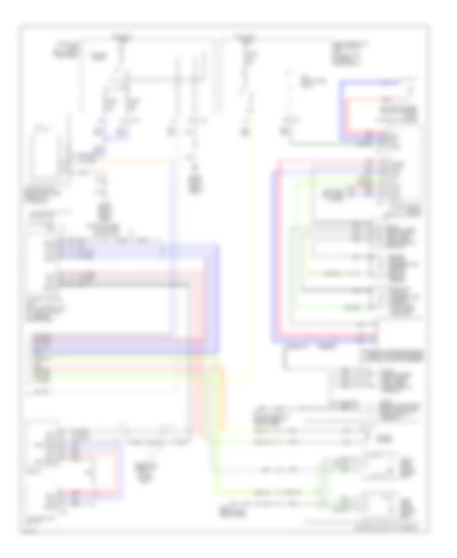
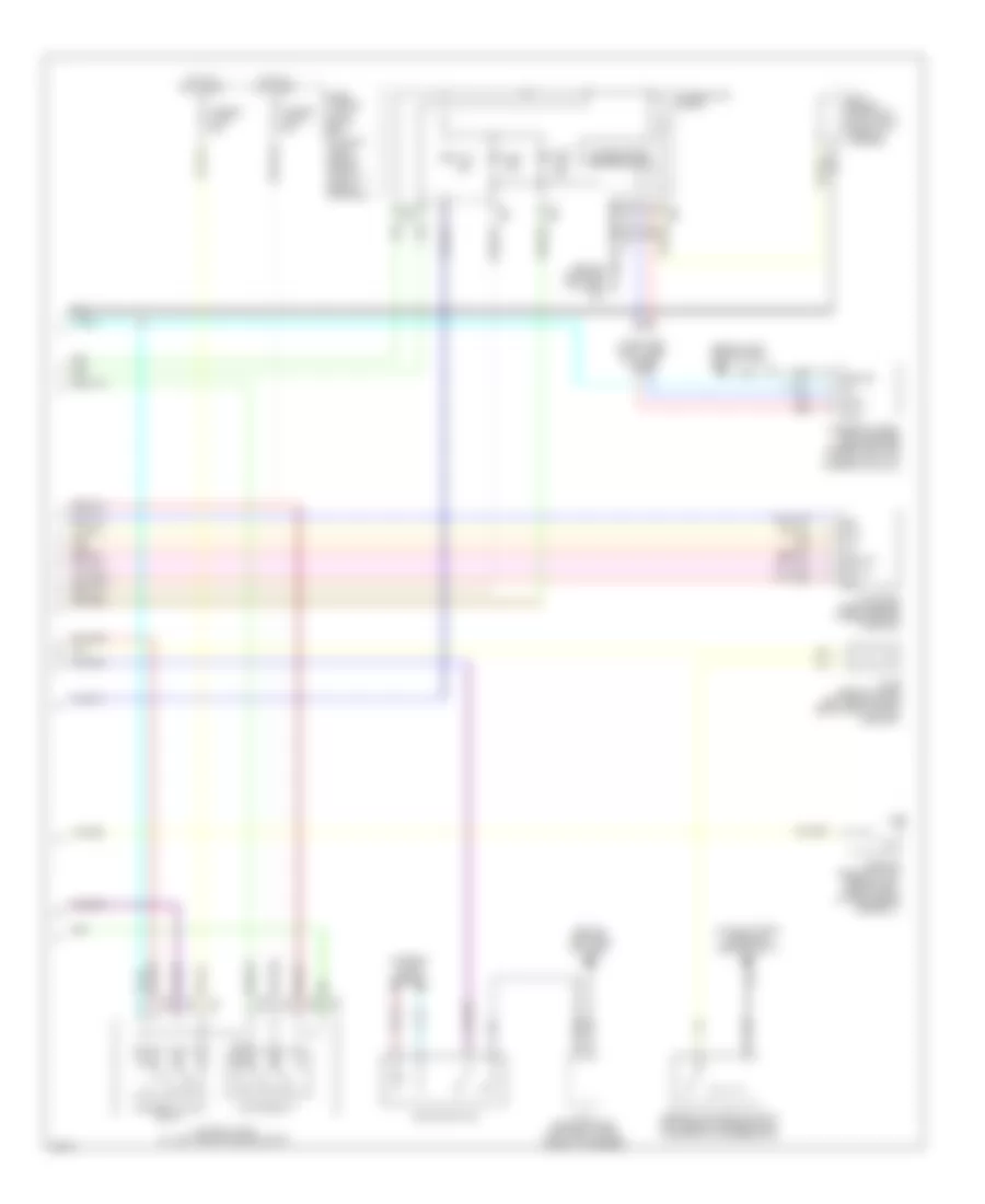
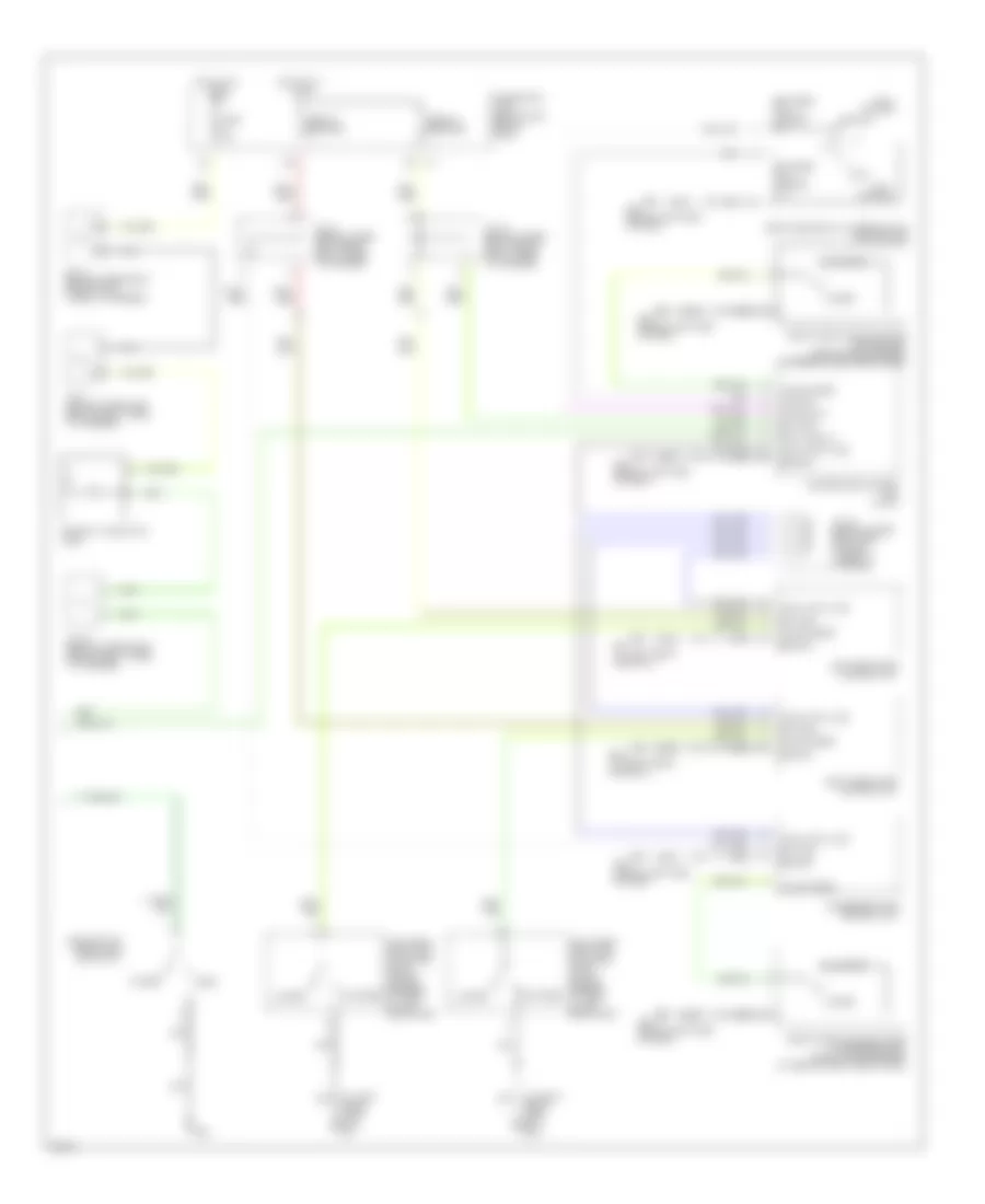
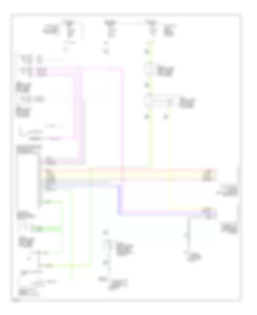
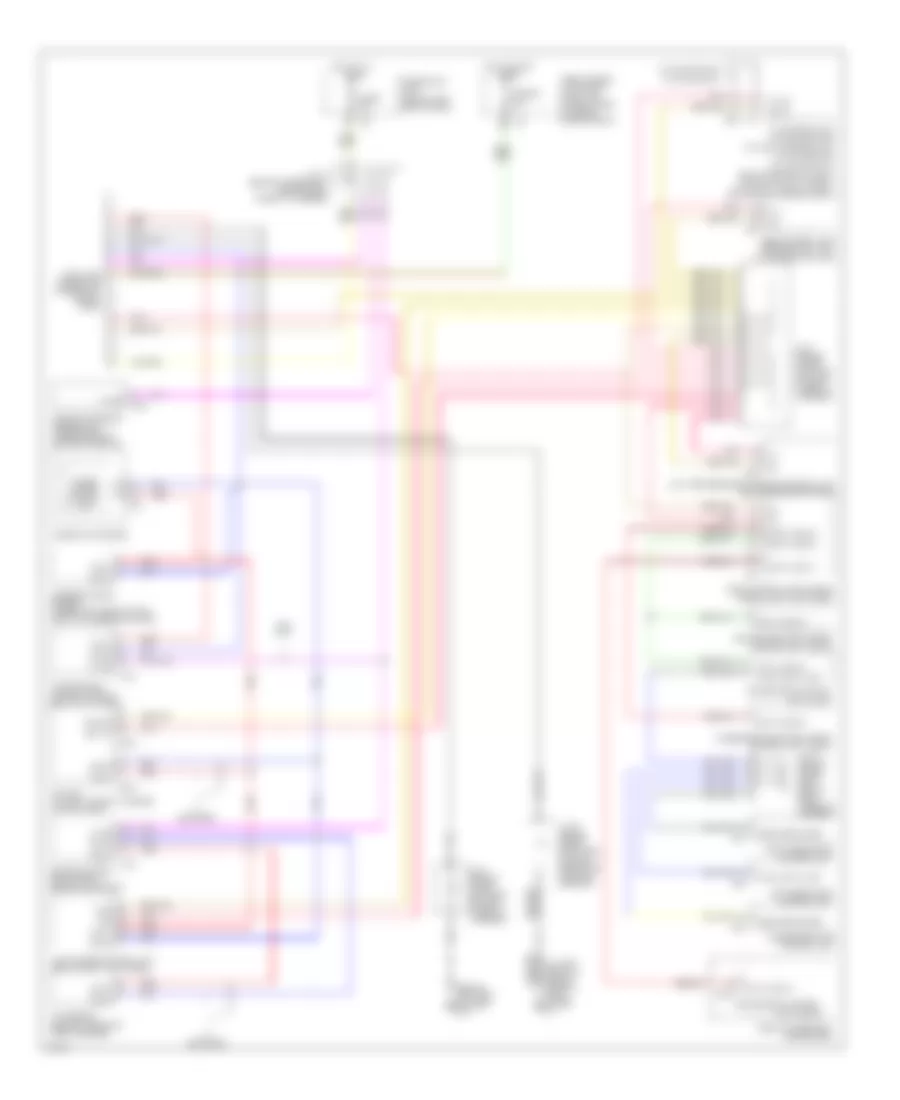
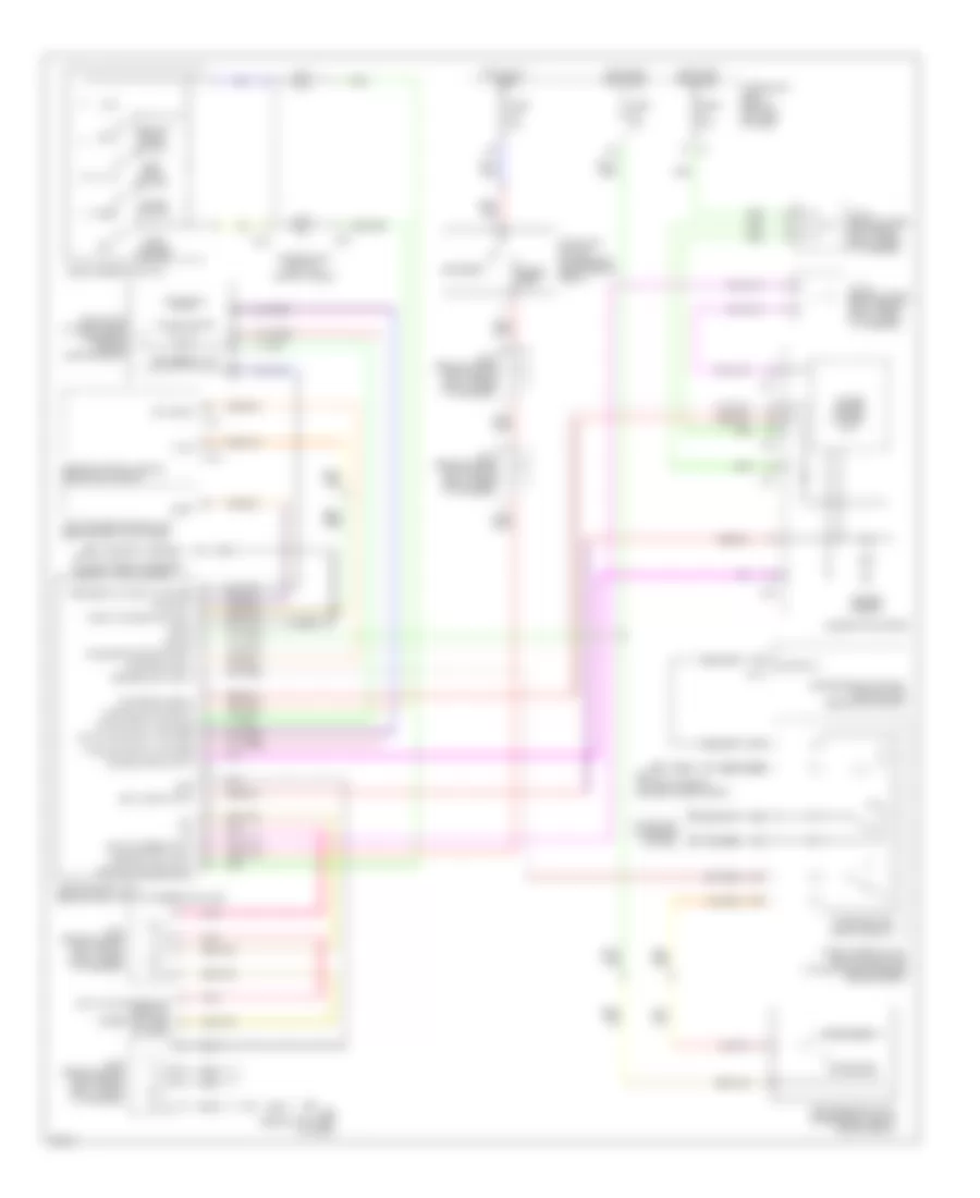
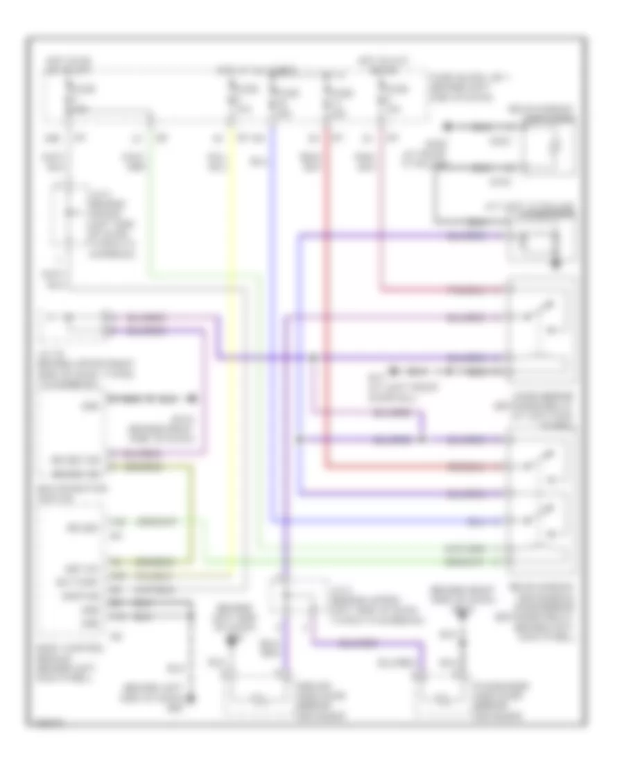
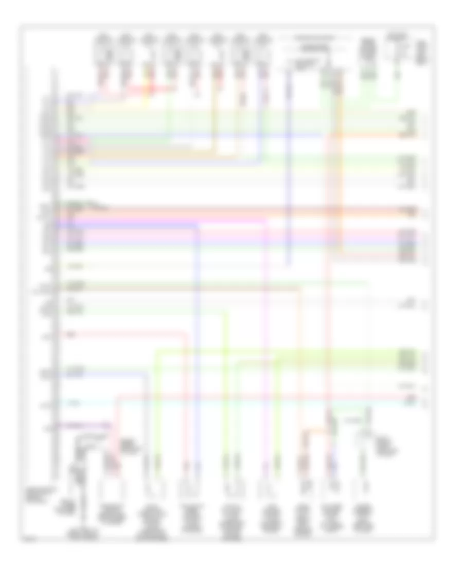
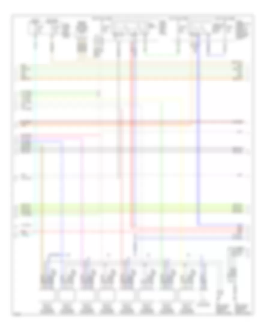
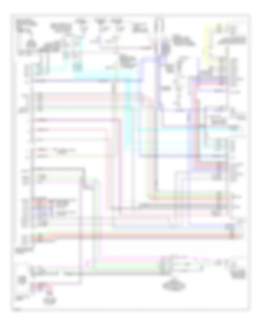
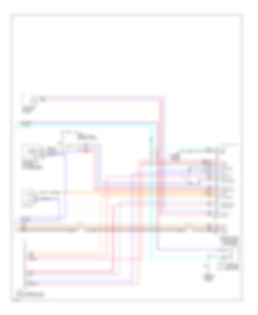
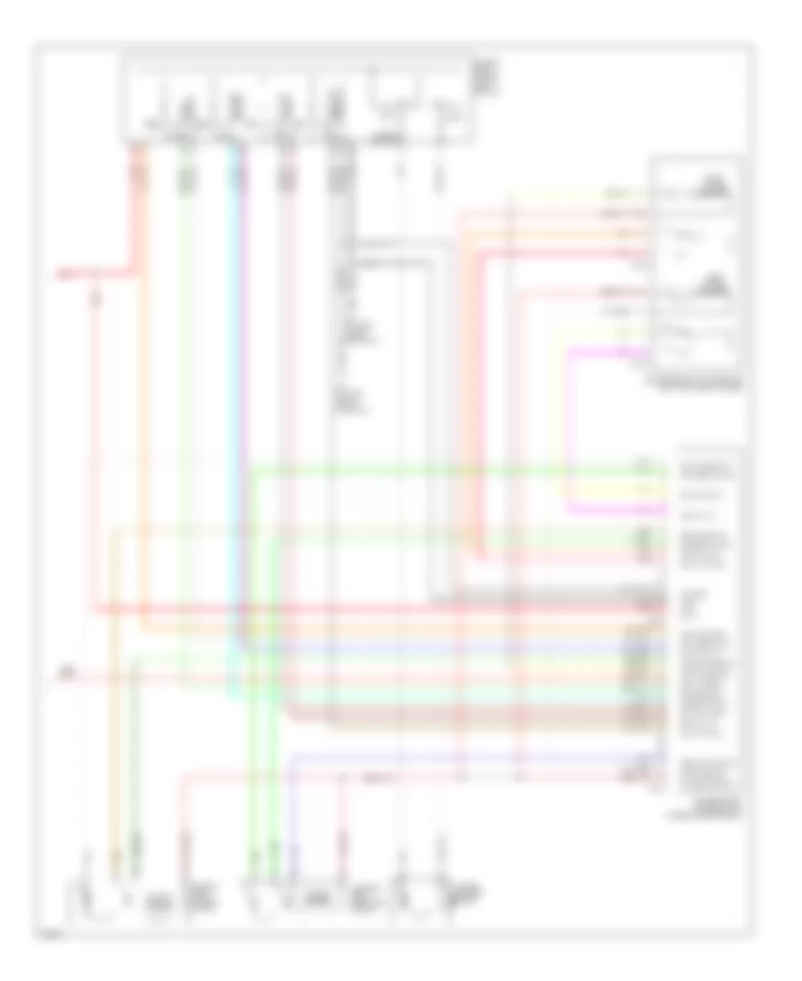
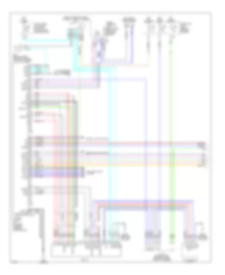
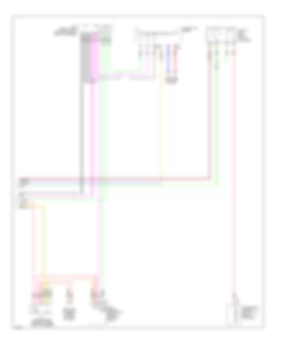
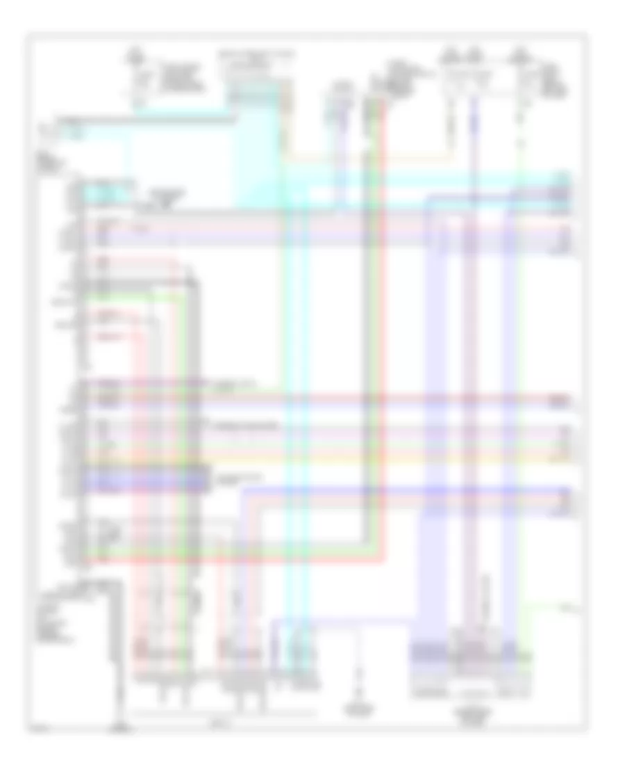
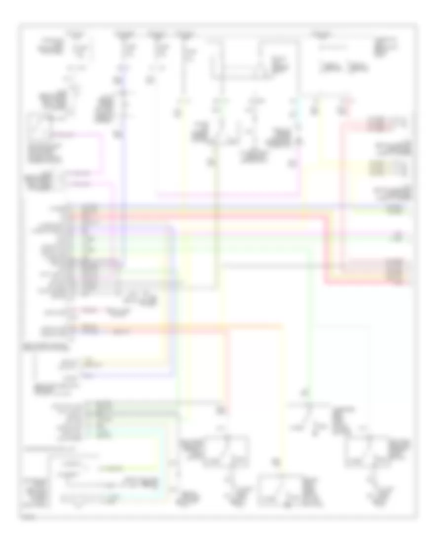
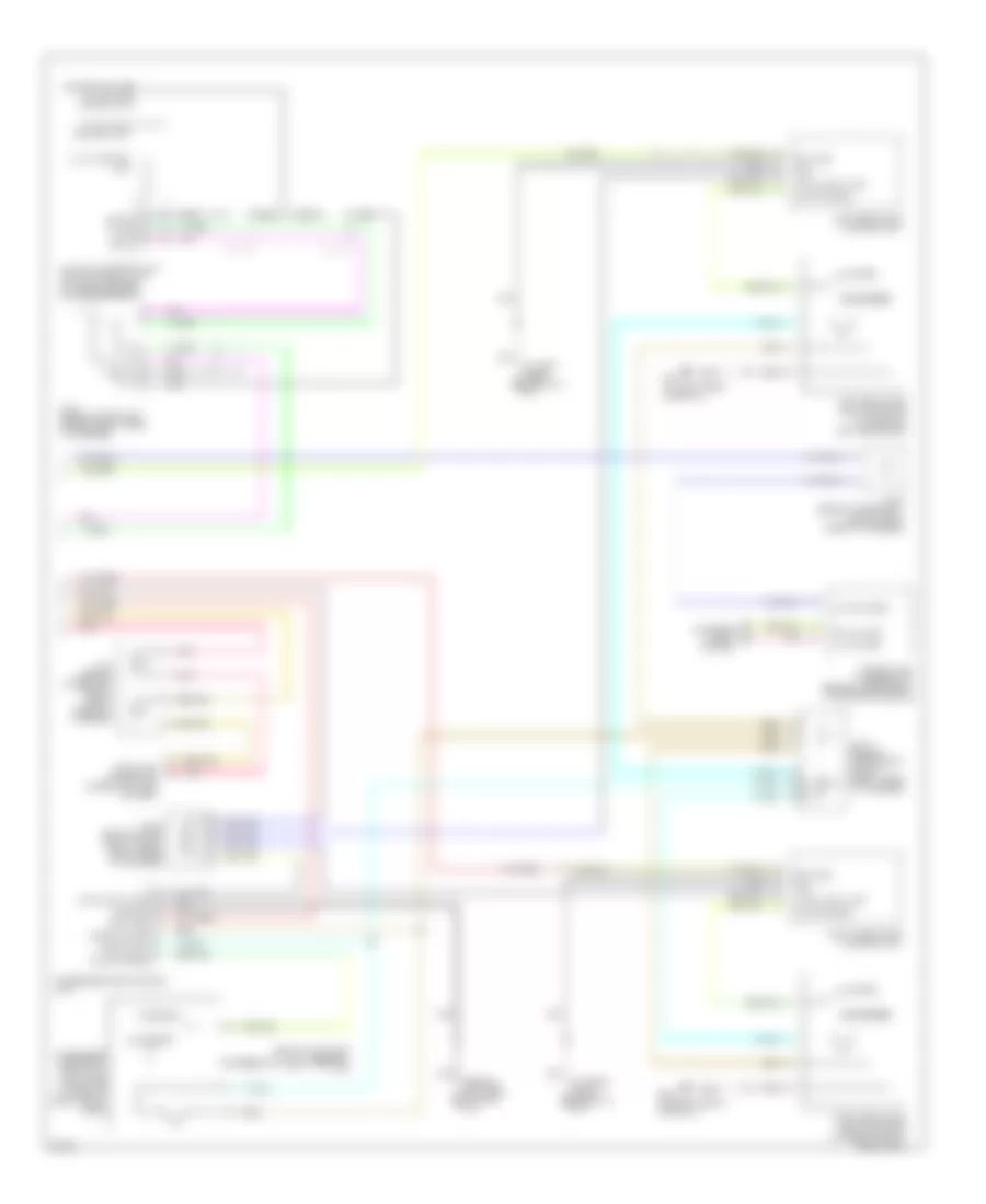
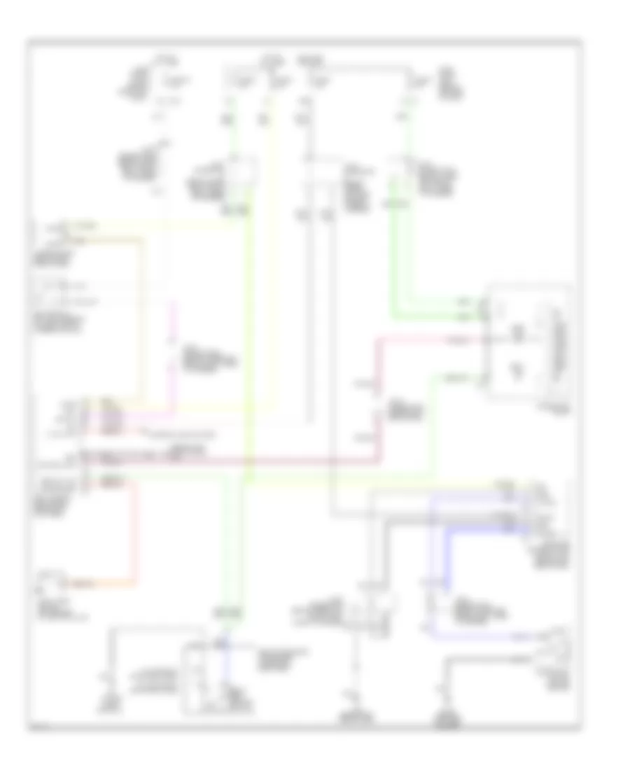
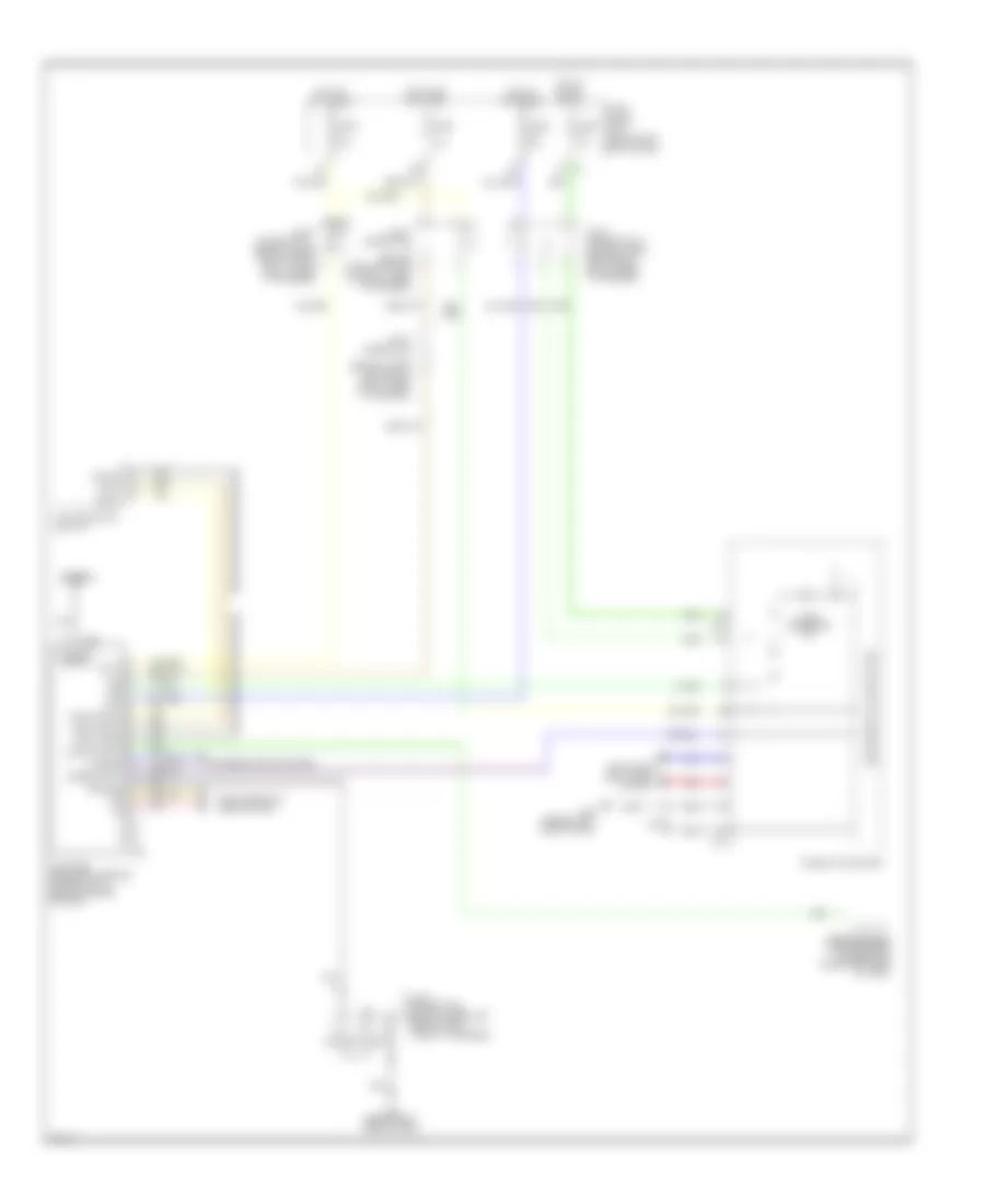
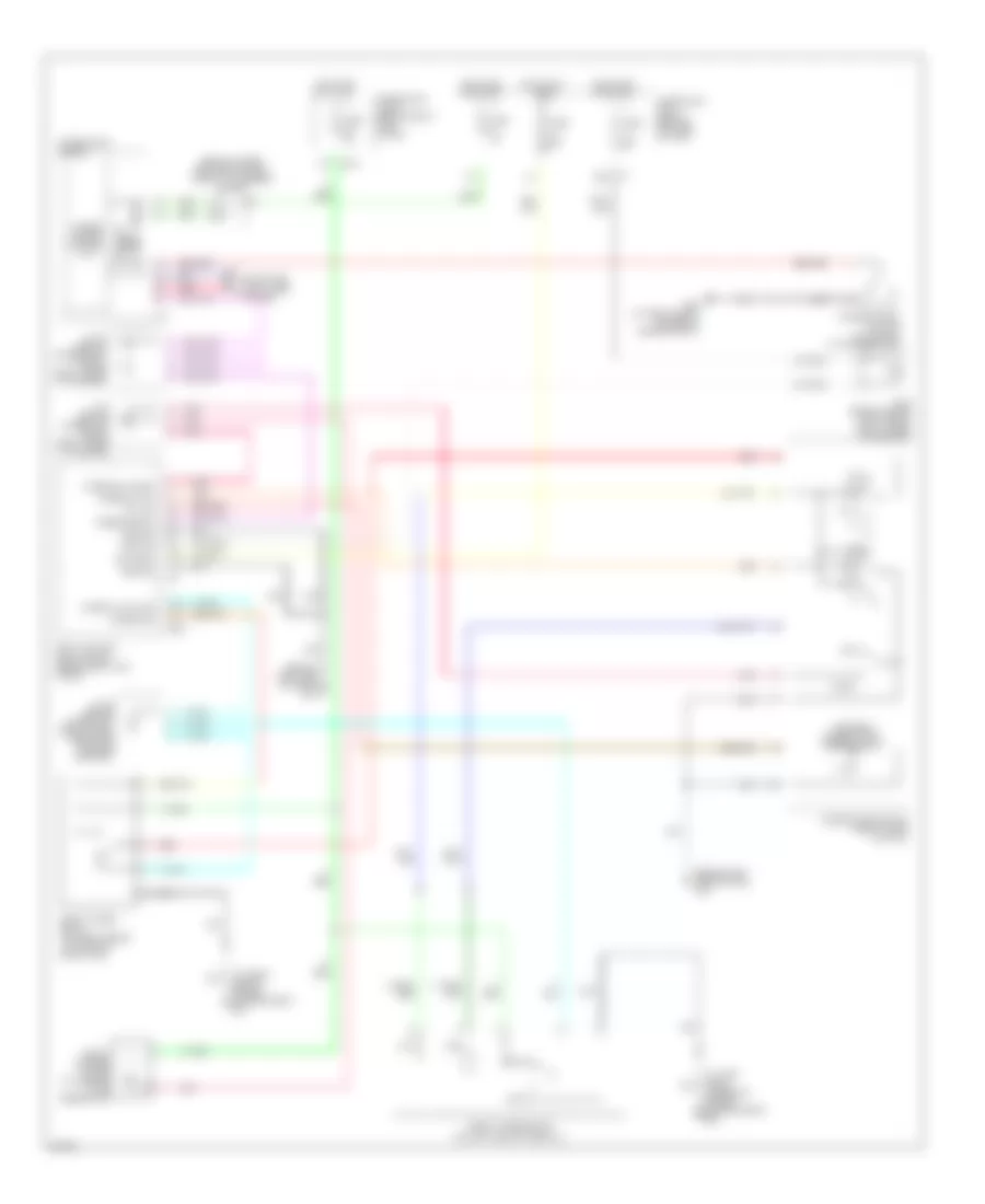
AIR CONDITIONING Automatic A/C Wiring Diagram (1 of 2) for Infiniti M45 2004 List of elements for Automatic A/C Wiring Diagram (1 of 2) for Infiniti M45 2004: 53 (behind left side of dash) m25 (behind right side of dash) m114 (behind right side of dash) m115 A/c auto amplifier (behind right side of dash, near blower motor) A/c-av (fr tx) Acc Air mix door motor (passenger side) (behind right side of dash, on heater unit) Amb sens Ambient sensor (behind center of front bumper) Av-a/c (fr rx) Bat Clk (fr) Combination meter Comp on comp on Compressor (at left front of engine) Computer data lines system Ecm comp Ecv Ecv solenoid valve F10 Fan on Fan pwm Fuse 10a Fuse block (j/b) 1 (behind left end of dash) Gnd Hot at all times Hot in acc or on Hot in on or start Ign In-vehicle sensor (behind lower center of dash) Incar sens Intake door motor (under right side of dash, on intake unit) Intake sens J/c 11 (behind upper right side of dash, taped to harness) J/c 14 (behind upper right side of dash, taped to harness) J/c 16 (behind upper right side of dash, taped to harness) J/c 19 (behind upper right side of dash, taped to harness) Lan sig M119 M120 M41 M42 Magnetic clutch Mode door motor (passenger side) (behind lower right side of dash, on heater unit) Pnk Red Sens gnd Speed sens Sun load sensor (under top left side of dash) Sun sens Unified meter control unit Vactr W/t sens Automatic A/C Wiring Diagram (2 of 2) for Infiniti M45 2004 List of elements for Automatic A/C Wiring Diagram (2 of 2) for Infiniti M45 2004: 56 11r 18r Ac-av Acclk Acrly Air conditioner relay Air mix door motor (driver side) Av & navi control unit (or av control unit) (at front center of luggage compartment) Av-ac Avcc Blower motor (below right side of dash, on intake unit) Blower relay Bus + Bus - Bus shield Can-h Can-l Computer data lines system Connector used w/ av & navi control unit Cooling fan speed control solenoid valve (on front of engine) Display Engine control module (behind glove box) Engine coolant temperature sensor (on top rear of engine) F101 F102 F8 (at left front of engine, near oil level gauge) Fuse 10a Fuse 15a Fuse block (j/b) 2 (behind right kick panel) Fuse, fusible link & relay block (j/b) (at right side of engine compartment) Gnd-a Heater & cooler unit assembly Hot at all times Intake sensor J/c 28 (behind upper right side of dash, near pass-through grommet) J/c 29 (behind upper right side of dash, near pass-through grommet) J/c 30 (behind upper right side of dash, near pass-through grommet) M114 (behind right side of dash) M115 (behind right side of dash) M144 M145 M83 Mode door motor (driver side) Multifunction switch Nca Pdpres Pnk Prf+ Prf- Radiator coolant temperature sensor (at bottom left side of radiator) Red Refrigerant pressure sensor (front right side of engine compartment, near condenser) Shield Twrf W/ av & navi control unit W/ av control unit
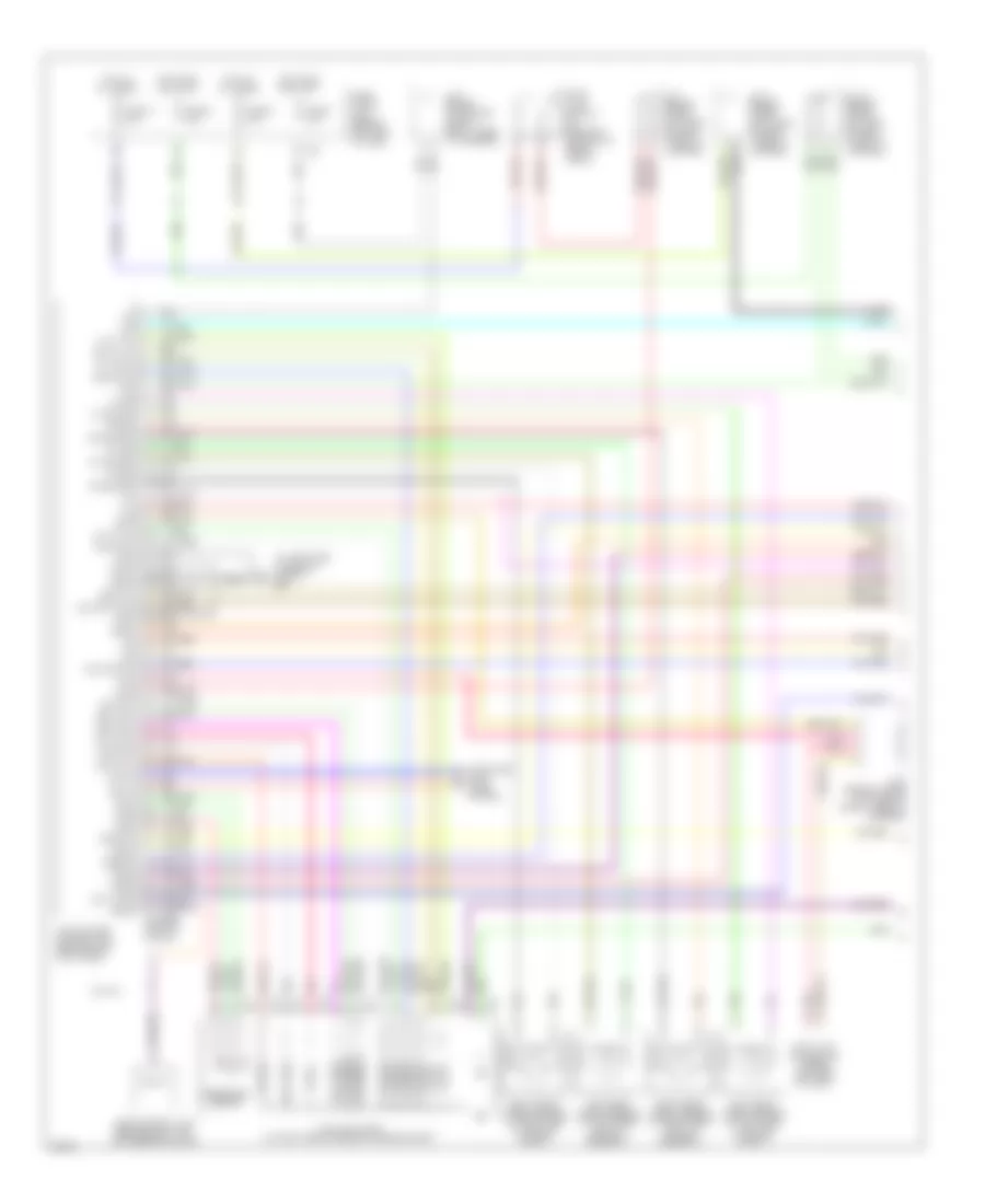
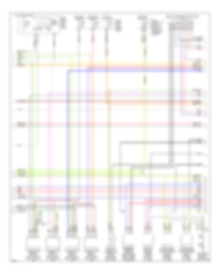
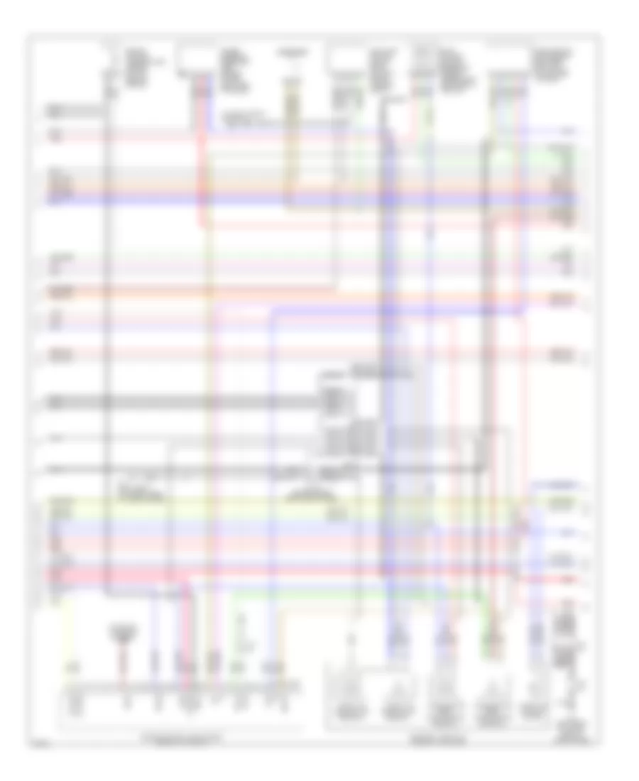
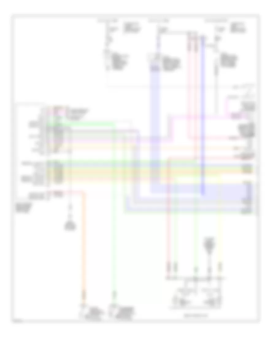
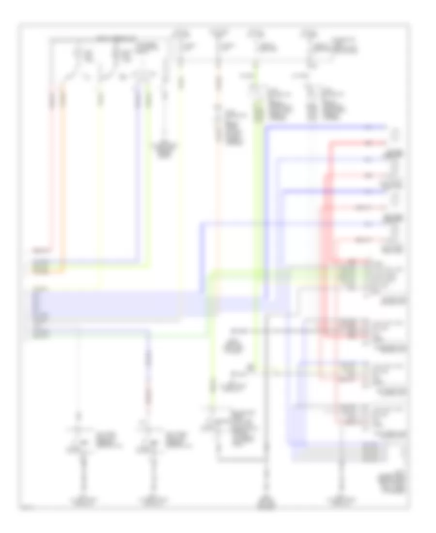
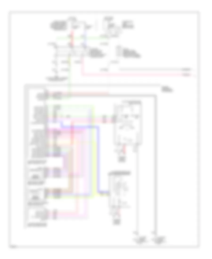
ANTI-LOCK BRAKES Anti-lock Brakes Wiring Diagram (1 of 2) for Infiniti M45 2004 List of elements for Anti-lock Brakes Wiring Diagram (1 of 2) for Infiniti M45 2004: 90 (at left side of engine compt) e67 (unused pins not shown) Abs w/l Ascd Ascd control unit (behind dash, left of steering column) Av1(fr) Av2(rl) Av3(rr) Av4(fl) Bls Can-h Can-l Computer data lines system Data link connector (under left side of dash) E21 E22 E23 Ev1(fr) Ev2(rl) Ev3(rr) Ev4(fl) Fl mv-av Fl mv-ev Fl ss Fl ss gnd Fr mv-av Fr mv-ev Fr ss Fr ss gnd Fuse 17 15a Fuse 6 10a Fuse 7 10a Fuse 9 10a Fuse block (j/b) 1 (behind left end of dash) Gnd Gnd1 Gnd2 Hot at all times Hot in on or start J/c 10 (behind upper left end of dash, taped to harness) J/c 11 (behind upper right side of dash, taped to harness) J/c 7 (behind upper left side of dash, taped to harness) J/c 8 (behind lower left side of dash, taped to harness) J/c 9 (behind lower left side of dash, taped to harness) Left front wheel sensor (at left side of engine compt) Left rear wheel sensor (at left rear spindle assembly) Lis Mav1(mc2) Mav2 (mc1) Nca Pkb sw Pnk Pressure sensor Pri usv Pri-mav Psm Pss Psu Red Right front wheel sensor (at right side of engine compt) Right rear wheel sensor (at right rear spindle assembly) Rl mv-av Rl mv-ev Rl ss Rl ss gnd Rr mv-av Rr mv-ev Rr ss Rr ss gnd Rxd Sec mav Sec usv Slip lamp Stop lamp switch (on bracket, above the brake pedal) Tcs in Txd Usv1(mc2) Usv2(mc1) Vcc Vdc actuator (at right rear corner of engine compt) Vdc off lamp Vdc off sw Vdc/tcs/abs control unit (behind right kick panel) Vout W/o icc Yrsm Yrsrff Yrss Yrst Yrsu Anti-lock Brakes Wiring Diagram (2 of 2) for Infiniti M45 2004 List of elements for Anti-lock Brakes Wiring Diagram (2 of 2) for Infiniti M45 2004: 40 (at right front corner of engine compt) e42 (behind left side of dash) m25 12v Abs ind Bite Brake fluid level switch (left rear of engine compt, on brake fluid reservoir) Bs out Can-h Can-l Combination meter Computer data lines system Drs out E55 E56 E57 Fuse, fusible link & relay box (at right front side of engine compt, in engine room box) Fusible link f 30a Fusible link k 50a Gnd Ground Hot at all times Interior lights system J/c 25 (behind lower left side of dash) near pass-through grommet) J/c 3 (behind upper left end of dash, taped to harness) J/c 5 (behind upper left side of dash, taped to harness) M41 M42 Motor relay Nca Parking brake switch (behind left side of dash, at park brake assembly) Red Ref Slip ind Solenoid valve relay Steering wheel angle sensor (under left side of dash, right of steering column) Unified meter control unit Vdc off ind Vdc off switch Vdc relay box (at left side of engine compt) Yaw rate/ side g sensor (under center console)
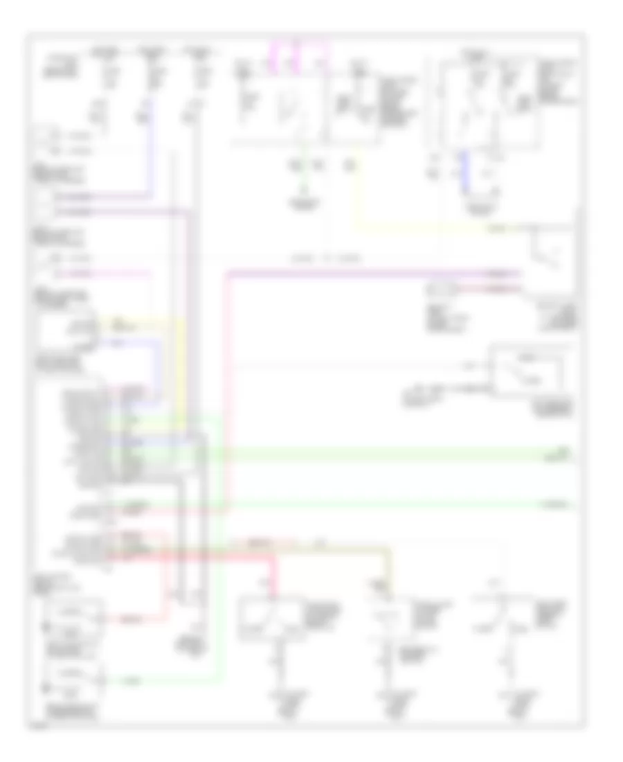
ANTI-THEFT Forced Entry Wiring Diagram (1 of 2) for Infiniti M45 2004 List of elements for Forced Entry Wiring Diagram (1 of 2) for Infiniti M45 2004: 57 (at right front door sill) b217 (behind left side of dash) m24 13r 1r e3 20b 25r Accessory B17 (at left front door sill) Battery Between full stroke & neutral Body control module (behind left kick panel) Closed Data line a-3 Data out Door sw (as) Door sw (dr) Door sw (rl) Door sw (rr) E204 Front door switch (driver side) (at left "b" pillar) Front door switch (passenger side) (at right "b" pillar) Fuse 10a Fuse 15a Fuse 20a Fuse block (j/b) 1 (behind left end of dash) Fuse, fusible link & relay block (j/b) (at right side of engine compartment) Fuse, fusible link & relay box (at right side of engine compartment, in engine room box) Ground Head- lamp relay Headlamp rly Headlights system Hood sw Horn chirp Hot at all times Hot in acc or on Hot in on or start Ignition J/c 10 (behind upper left end of dash, taped to harness) J/c 5 (behind upper left side of dash, taped to harness) J/c 9 (behind lower left side of dash, taped to harness) K/less gnd K/less power K/less signal Left rear door lock assembly (door switch) M1 4a Open Pnk Power Remote keyless entry receiver (at left "c" pillar) Right rear door lock assembly (door switch) Security horn (at right front engine compartment) Security horn relay (at left rear of engine compartment) Theft ind Trunk lid key cylinder switch (unlock switch) Trunk room lamp switch (at center rear of trunk lid) Trunk sw Trunk unlock sw Forced Entry Wiring Diagram (2 of 2) for Infiniti M45 2004 List of elements for Forced Entry Wiring Diagram (2 of 2) for Infiniti M45 2004: 42 (at left front door sill) b17 (at right front door sill) b217 B17 (at left front door sill) B217 (at right front door sill) Bat (c/b) Between full stroke & n Circuit breaker Closed Data line a-3 Driver door control unit (lcu01) E42 Front door key cylinder switch (driver side) Front door lock actuator (driver side) (door unlock sensor) (at rear of left front door) Front door lock actuator (passenger side) (door unlock sensor) (at rear of right front door) Full stroke Fuse 10a Fuse block (j/b) 1 (behind left end of dash) Ground Hood switch (near hood lock stay) Hot at all times J/c 11 (behind upper right side of dash, taped to harness) J/c 15 (behind upper right side of dash, taped to harness) J/c 16 (behind upper right side of dash, taped to harness) J/c 21 (behind upper left side of dash, taped to harness) J/c 3 (behind upper left end of dash, taped to harness) Left rear door control unit Left rear door lock actuator (door unlock sensor) (at rear of left rear door) Local data line Lock Lock sw Locked M24 (behind left side of dash) Nca Open Passenger door control unit Right rear door control unit Right rear door lock actuator (door unlock sensor) (at rear of left rear door) Security indicator lamp Unlock Unlock sens Unlock sw Unlocked Immobilizer Wiring Diagram for Infiniti M45 2004 List of elements for Immobilizer Wiring Diagram for Infiniti M45 2004: 26 (at left front of engine, near oil level gauge) f8 (behind left side of dash) m25 20b Engine control module (behind glove box) F102 Fuse 10a Fuse block (j/b) 1 (behind left end of dash) Fuse block (j/b) 2 (behind right kick panel) Hot at all times Hot in on or start Im line Inserted J/c 11 (behind upper right side of dash, taped to harness) J/c 16 (behind upper right side of dash, taped to harness) J/c 20 (behind upper right side of dash, taped to harness) J/c 29 (behind upper right side of dash, near pass-through grommet) J/c 3 (behind upper left end of dash, taped to harness) J/c 5 (behind upper left side of dash, taped to harness) Key switch & key lock solenoid (key switch) (at right side of steering column) M145 Nats antenna amplifier (behind lower left side of dash) Nats immu (behind dash, left of steering column) Red Security indicator lamp Steering lock control unit (behind center of dash) Withdrawn
BODY CONTROL MODULES Body Computer Module Wiring Diagram (1 of 2) for Infiniti M45 2004 List of elements for Body Computer Module Wiring Diagram (1 of 2) for Infiniti M45 2004: 62 Acc Auto sens Auto sens (5v) Auto sens (gnd) Body control module (bcm) (behind left kick panel) Chime Combo sw (auto) Data link connector (under left side of dash) Defog sw Defogger system Detent sw (key) Door locks system Door sw (as) Door sw (rl) Exterior lights system Flasher Fuse 14 10a Fuse 21 10a Fuse block (j/b) 1 (behind left end of dash) Gnd Hdlt relay Headlights system Hot in acc or on Hot in start Iiurx Iiutx Instrument cluster system Int (vr) Joint connector 10 (behind upper left end of dash, taped to harness) Joint connector 8 (behind lower left side of dash, taped to harness) K/less gnd K/less pwr (5v) K/less sig Light sw (1st) M24 (behind left side of dash) Memory sw 1 Memory sw 2 Memory systems Mirror sw down Mirror sw left Mirror sw right Mirror sw up Mirrors system Navigation system Pnk Red Select sw lh Select sw rh Set sw Speed sig Tail relay Telesco sw (fr) Telesco sw (rr) Tilt sens Tilt sw (down) Tilt sw (up) Tilt tele ss gnd Tilt/tele sen pwr Warning system Wiper sw (int) Wiper sw (wash) Wiper/washer system Body Computer Module Wiring Diagram (2 of 2) for Infiniti M45 2004 List of elements for Body Computer Module Wiring Diagram (2 of 2) for Infiniti M45 2004: 66 (or pnk) 20b All off Anti-theft system Batt Body control module (bcm) (behind left kick panel) Circuit breaker 1 Computer data lines system Data line a-1 Data line a2 Data line a3 Defogger system Door locks system Door sw (dr) Door sw (rr) Door warn lmp E204 Exterior lights system Fuse 1 10a Fuse 3 10a Fuse block (j/b) 1 (behind left end of dash) Gnd Headlights system Hood sw Horn chirp Hot at all times Hot in on or start Ign Ign key ill Instrument cluster system Interior lights system Joint connector 5 (behind upper left side of dash, taped to harness) Key switch M24 (behind left side of dash) Map/l (lh) Map/l (rh) Mem ind 2 Memory ind 1 Memory systems Personal lmp sw Pnk Rap output Red Rev-lmp sw Rl personal lmp Rr def Rr personal lmp Seat belt sw (dr) Tele motor (fr) Tele motor (rr) Telesco sens Theft ind Tilt motor (down) Tilt motor (up) Tilt tele batt Tilt tele gnd Total ill Trunk opener Trunk opener sw Trunk sw Trunk unlock sw Trunk, tailgate, fuel doors system Warning system Wiper amp Wiper auto stop Wiper/washer system
COMPUTER DATA LINES Computer Data Lines Wiring Diagram for Infiniti M45 2004 List of elements for Computer Data Lines Wiring Diagram for Infiniti M45 2004: 77 (at left front of engine near oil level gauge) f8 (behind left end of dash) (behind left side of dash) m25 (under left side of dash) (w/navigation: at front center of luggage compt) (w/o navigation: 33r Air bag diagnosis sensor unit (under rear of center console) Ascd control unit (behind dash, left of steering column) Av & navi control unit (w/ navigation) Av control unit (w/o navigation) Av-cn B143 B243 B244 B29 Behind center of dash) Body control module (bcm) (behind left kick panel) Can-h Can-l Cn-av Combination meter D38 D58 D78 Data line a1 Data line a2 Data line a3 Data link connector Ddl-rx Ddl-tx Driver door control unit (lcu01) Driver seat control unit (lcu02) Driver side door mirror control unit (lcu03) Engine control module (ecm) (behind glove box) F102 F103 Front power seat (driver side) Fuse 58 10a Fuse 6 10a Fuse block (j/b) 1 Fuse, fusible link & relay block (j/b) (at right side of engine compartment) Hot at all times Hot in on or start Icc sensor (behind center of front bumper) Icc unit (on right side of luggage compartment) If equipped J/c 11 (behind upper right side of dash, taped to harness) J/c 15 (behind upper right side of dash, taped to harness) J/c 29 (behind upper right side of dash, near pass through grommet) J/c 5 (behind upper left side of dash, taped to harness) J/c 8 (behind lower left side of dash, taped to harness) K-line Kline Left rear door control unit Local data line Low tire pressure warning control unit (behind center of dash) M103 M35 M41 M77 Non dtc Passenger door control unit Passenger side door mirror control unit (lcu04) Pnk Red Right rear door control unit Rxd Rxi Steering angle sensor (under left side of dash, right of steering column) Transmission control module (behind glove box) Txd Txi Unified meter control unit Vdc/tcs/abs control unit (behind right kick panel) W/ navigation W/o navigation
CRUISE CONTROL Cruise Control Wiring Diagram for Infiniti M45 2004 List of elements for Cruise Control Wiring Diagram for Infiniti M45 2004: 81 14r 15r 21r 24r 29r 31r A solenoid monitor input Actr output high side Air valve Air valve output low side Ascd Ascd brake switch (on bracket, above brake pedal) Ascd control unit (behind dash, left of steering column) Ascd pump (at right rear corner of engine compartment) Ascd steering switch Brake nc sw input Brake no sw input Cancel switch Combination meter Combination switch (spiral cable) Control sw ad input Control sw gnd input Cruise (green) Cruise lamp output Data link connector (partial) (under left side Depre- ssed Depressed E24 (at right side of engine compartment) Ecm prun input Engine control module (behind glove box) Etc prun F101 F102 F104 F8 (at left front of engine, near oil level gauge) Fuse 10a Fuse 15a Fuse block (j/b) 1 (behind left end of dash) Fuse, fusible link & relay block (j/b) (at right side of engine compartment) Gnd Gnd-c Hot at all times Hot in on or start Ign sw J/c 10 (behind upper left end of dash, taped to harness) J/c 16 (behind upper right side of dash, taped to harness) J/c 5 (behind upper left side of dash, taped to harness) J/c 7 (behind upper left side of dash, taped to harness) J/c 8 (behind lower left side of dash, taped to harness) M25 (behind left side of dash) M41 M42 M441 M53 Main (cruise) switch Od cancel signal Of dash) Off Park/neutral position relay Pnk Release valve Release valve out low side Released Resume/ accel switch Rxi Set Set lamp output Set/ coast switch Start rly Starting/ charging system Stoplight switch (on bracket, above brake pedal) Tcs input Throttle position input Transmission control module (tcm) (behind glove box) Tvoo Txi Unified meter control unit Vacuum motor Vacuum mtr out low side Vdc/tcs/abs control unit (behind right kick panel) Vehicle speed input Intelligent Cruise Control Wiring Diagram (1 of 2) for Infiniti M45 2004 List of elements for Intelligent Cruise Control Wiring Diagram (1 of 2) for Infiniti M45 2004: 70 14r 15r 21r 24r 29r 31r B243 B244 Bat-1 Bat-2 Bnc-sw Bno-sw Brake pressure sensor (at left rear corner of engine compartment) Buzz Can-h Can-l Combination meter Computer data lines system Corner of trunk) b257 Cruise (green) Data link connector (dlc) (partial) (under left side of dash) Ddl-rx Ddl-tx Depressed E24 (at right side of engine compartment) F104 Fuse 10a Fuse 15a Fuse block (j/b) 1 (behind left end of dash) Fuse, fusible link & relay block (j/b) (at right side of engine compartment) Fuse, fusible link & relay box (at right side of engine compartment, in engine room box) Gnd Gnd-1 Gnd-2 Gnd-3 Hot at all times Hot in on or start Icc brake switch (on bracket, above brake pedal) Icc unit (on right side of luggage compartment) Ign-1 Ign-2 J/c 10 (behind upper left end of dash, taped to harness) J/c 8 (behind lower left side of dash, taped to harness) M41 M42 Park/neutral position relay Parking brake switch (behind left side of dash, at park brake assembly) Pkb sw Pnk Psen-gnd Psen-pwr Psen-sig Red Released Rls-nc Rls-no Rls-pwr Sol+ Sol- Start rly Starting/ charging system Stp-lmp Transmission control module (tcm) (behind glove box) Unified meter control unit (with icc indicator) Vout Vpwr Warn Wip-h Wip-l Wiper/washer system Intelligent Cruise Control Wiring Diagram (2 of 2) for Infiniti M45 2004 List of elements for Intelligent Cruise Control Wiring Diagram (2 of 2) for Infiniti M45 2004: 53 (at right front door sill) b217 (at right side of engine compartment) e24 19b Accelerate/ resume switch Air valve Ascd pump (at right rear corner of engine compartment) B245 Boost solenoid Brake booster (at left rear of engine compt) Can-h Can-l Cancel switch Coast/ set switch Combination switch (spiral cable) Computer data lines system Cruise Distance switch Engine control module (behind glove box) F102 Fuse 10a Fuse block (j/b) 1 (behind left end of dash) Gnd Gnd-a Gnd-s Hot in on or start Icc brake hold relay (at left rear of engine compartment) Icc sensor (behind center of front bumper) Icc steering switch Icc unit (on right side of luggage compartment) Icc warning chime (below lower left side of dash) Ignition J/c 1 (behind upper left end of dash, taped to harness) J/c 25 (behind lower left side of dash, near pass-through grommet) J/c 3 (behind upper left end of dash, taped to harness) J/c 30 (behind upper right side of dash, near pass-through grommet) J/c 7 (behind upper left side of dash, taped to harness) M441 M53 Nca Od-cancel On/off switch Pnk Red Release valve Safety Stoplight switch (on bracket, above brake pedal) Strg gnd Strg sig T-rly Tvo Tvoo Vacuum motor Vent
DEFOGGERS Defoggers Wiring Diagram for Infiniti M45 2004 List of elements for Defoggers Wiring Diagram for Infiniti M45 2004: 32 (at left "c" pillar) condenser (behind left side of dash) m24 (behind right side of dash) m114 20b B17 (at left front door sill) B181 B421 B422 (at right "c" pillar) Battery Body control module (behind left kick panel) Def sw Door mirror defogger relay (at left kick panel) Driver side door mirror defogger Fuse 10a Fuse 20a Fuse block j/b 1 (behind left end of dash) Gnd Hot at all times Hot in acc or on Hot in on or start Ignition J/c 19 (behind upper right side of dash, taped to harness) J/c 2 (behind upper left side of dash, taped to harness) J/c 5 (behind upper left side of dash, taped to harness) M114 (behind right side of dash) Multifunction switch Passenger side door mirror defogger Rear window defogger Rear window defogger & door mirror defogger relay (behind left kick panel) Rr def Rr def f/b Rr def on
ELECTRONIC MUFFLER Electronic Muffler Wiring Diagram for Infiniti M45 2004 List of elements for Electronic Muffler Wiring Diagram for Infiniti M45 2004: 16 (behind upper right side of dash, taped to harness) joint connector 19 B256 (at right front corner of trunk) Close output Dual mode muffler actuator (at left rear of vehicle) Dual mode muffler control unit (at right side of luggage compartment) Engine control module (ecm) (behind glove box) F101 F102 Fuse 1 10a Fuse block (j/b) 1 (behind left end of dash) Ground Hot in on or start Ignition Open output Tachometer Tvo0
ELECTRONIC POWER STEERING Electronic Power Steering Wiring Diagram for Infiniti M45 2004 List of elements for Electronic Power Steering Wiring Diagram for Infiniti M45 2004: 28 (behind right side of dash) Can-h Can-l Combination meter E62 (at left front corner of engine compt) Engine control module (ecm) (behind glove box) F101 Fuse 10a Fuse block (j/b) 1 (behind left end of dash) Gnd Hot in on or start Joint connector 10 (behind upper left end of dash, taped to harness) Joint connector 16 (behind upper right side of dash, taped to harness) Joint connector 19 (behind upper right side of dash, taped to harness) Joint connector 9 (behind lower left side of dash, taped to harness) M114 M24 (behind left side of dash) M41 M42 Power steering control unit (behind right side of dash) Power steering solenoid valve (on steering rack assembly) Red Sol Tacho Unified meter control unit Vdc/tcs/abs control unit (behind right kick panel) Vign Vsp Power Tilt Steering Column Wiring Diagram for Infiniti M45 2004 List of elements for Power Tilt Steering Column Wiring Diagram for Infiniti M45 2004: 32 (behind lower left side of dash, taped to harness) joint connector 8 Backward Bat Body control module (bcm) (behind left kick panel) Circuit breaker 1 Data link connector (under left side of dash) Down E203 Forward Fuse 10a Fuse block (j/b) 1 (behind left end of dash) Fuse, fusible link & relay box (at right side of engine compt, in engine room box) Fusible link h 40a Gnd Hot at all times M24 (behind left side of dash) M25 (behind left side of dash) Pnk Steering position switch Telesco mtr (fr) Telesco mtr (rr) Telesco sw (fr) Telesco sw (rr) Telescopic motor (behind left side of dash) Telescopic switch Tilt motor (behind left side of dash) Tilt mtr (down) Tilt mtr (up) Tilt sw (down) Tilt sw (up) Tilt switch Tilt tele bat
ENGINE PERFORMANCE
4.5L 4.5L, Engine Performance Wiring Diagram (1 of 5) for Infiniti M45 2004 List of elements for 4.5L, Engine Performance Wiring Diagram (1 of 5) for Infiniti M45 2004: 66 (behind upper left end of dash) j/c 10 (behind upper right side of dash) A/c system Acrly Ascd control unit (behind dash, left of steering column) Combination meter Cooling fan speed control solenoid valve (on front of engine) Crankshaft position sensor (pos) (bottom rear of engine) Crtn Cvbv Dual mode muffler control unit (at right of luggage compt) Engine control module (ecm) (behind glove box) Etc prun Evap Evap canister purge volume control solenoid valve (under rear of vehicle, on evap canister) F8 (left front of engine, near oil level gauge) Fpcm Fpr Fuel injector Fuse 10a Fuse block (j/b) 1 (left end of dash) Hot in on or start Ign 1 Ign 2 Ign 3 Ign 4 Ign 5 Ign 6 Ign 7 Ign 8 Ignsw Inj 1 Inj 2 Inj 3 Inj 4 Inj 5 Inj 6 Inj 7 Inj 8 J/c J/c 19 (behind upper right side of dash) J/c 28 Led Malfunction indicator lamp Motrly Nca O2hfl O2hfr O2hrl O2hrr Pnk Pos Power steering control unit (behind right side of dash) Prf+ Prf- Prun in Red Ssoff Stsw Tacho Tp in Tvo0 Unified meter control unit Vacuum cut valve bypass valve (under rear of vehicle, forward of evap canister) Vias Vias control solenoid valve (top front center of engine) 4.5L, Engine Performance Wiring Diagram (2 of 5) for Infiniti M45 2004 List of elements for 4.5L, Engine Performance Wiring Diagram (2 of 5) for Infiniti M45 2004: 28 (behind upper right side of dash) j/c 19 22r Condenser Ecm relay F8 (left front of engine, near oil level gauge) F9 (left front of engine, near oil level gauge) Fuse 10a Fuse 15a Fuse 20a Fuse block (j/b) 1 (left end of dash) Fuse block (j/b) 2 (right kick panel) Fuse, fusible link & relay block (j/b) (in right front side of engine compt) Hot at all times Hot in on or start Hot in start Ignition coil 1 (w/ power transistor) Ignition coil 2 (w/ power transistor) Ignition coil 3 (w/ power transistor) Ignition coil 4 (w/ power transistor) Ignition coil 5 (w/ power transistor) Ignition coil 6 (w/ power transistor) Ignition coil 7 (w/ power transistor) Ignition coil 8 (w/ power transistor) Nca Plug spark Red Spark plug Throttle control motor relay 4.5L, Engine Performance Wiring Diagram (3 of 5) for Infiniti M45 2004 List of elements for 4.5L, Engine Performance Wiring Diagram (3 of 5) for Infiniti M45 2004: 25 (behind upper right side of dash) j/c 30 33r 34r Camshaft position sensor (phase) (on front of left cyl head) F8 (left front of engine, near oil level gauge) Fuel pump relay Fuse 10a Fuse 15a Fuse block (j/b) 1 (left end of dash) Fuse block (j/b) 2 (right kick panel) Fuse, fusible link & relay block (j/b) (in right front side of engine compt) Heated oxygen sensor 1 (bank 1) (on inlet of left manifold twc) Heated oxygen sensor 1 (bank 2) (on inlet of right manifold twc) Heated oxygen sensor 2 (bank 1) (on outlet of left manifold twc) Heated oxygen sensor 2 (bank 2) (on outlet of right manifold twc) Hot at all times Hot in on or start Intake valve timing control position sensor (bank 1) (on front of left cyl head) Intake valve timing control position sensor (bank 2) (on front of right cyl head) J/c Nca Pnk Radiator coolant temperature sensor (bottom left side of radiator) Red Refrigerant pressure sensor (front right side of engine compt, near condenser) 4.5L, Engine Performance Wiring Diagram (4 of 5) for Infiniti M45 2004 List of elements for 4.5L, Engine Performance Wiring Diagram (4 of 5) for Infiniti M45 2004: 35 (at right front door sill) Accelerator pedal position (app) sensor 1 Accelerator pedal position (app) sensor 2 Aps1 Avcc2 B217 Batt Condenser Electric throttle control actuator Engine control module (ecm) (behind glove box) Engine coolant temperature sensor (on top rear of engine) Evap control system pressure sensor (under right rear side of vehicle) F8 (left front of engine, near oil level gauge) Fuel pump control module (fpcm) (on right side of luggage compt) Gnd a Gnd a2 Ivcpusl Ivcpusr J/c J/c 28 J/c 29 (behind upper right side of dash) Mass airflow (maf) sensor (between air duct & air cleaner housing) Nca Neut Pdpres Phase Pnk Power steering pressure (psp) sensor (lower right side of engine) Qa+ Red Starting/ charging system Throttle control motor Throttle position (tp) sensor 1 Throttle position (tp) sensor 2 Tps2 4.5L, Engine Performance Wiring Diagram (5 of 5) for Infiniti M45 2004 List of elements for 4.5L, Engine Performance Wiring Diagram (5 of 5) for Infiniti M45 2004: 52 (at left front door sill) b17 Aps2 Avcc Brksw Can h Can l Cdcv Computer data lines system Dropping resistor Engine control module (ecm) (behind glove box) Evap canister vent control valve (under rear of vehicle, on evap canister) F8 (left front of engine, F9 (left front of engine, Fgauge+ Fgauge- Fpcmck Ftprs Fuel level sensor unit & fuel pump (in fuel tank) Gnd c Gnd e Gnd m Im lime Intake valve timing control solenoid valve (bank 1) (on top front of left cyl head) Intake valve timing control solenoid valve (bank 2) (on top front of right cyl head) Ivcl Ivcr J/c J/c 15 (behind upper right side of dash) J/c 7 (behind upper left side of dash) Kline Knk1 Knk2 Knock sensor (bank 1) (below left side of intake manifold) Knock sensor (bank 2) (below right side of intake manifold) Motor 1 Motor 2 Nats immu (behind dash, left of steering column) Nca Near oil level gauge) O2sfl O2sfr O2srl O2srr Pnk Pspres Qa- Red Stop lamp switch (on bracket, above brake pedal) Tps1 Tvo0 Twrf Vmot
EXTERIOR LIGHTS Back-up Lamps Wiring Diagram for Infiniti M45 2004 List of elements for Back-up Lamps Wiring Diagram for Infiniti M45 2004: 13 B57 (at center rear of trunk) Back- up Back-up lamp relay Back-up lamp relay (at left kick panel) F104 Fuse 10a Fuse block (j/b) 1 (behind left end of dash) Hot in on or start Joint connector 10 (behind upper left end of dash, taped to harness) Left rear combination lamp Red Right rear combination lamp Transmission control module (tcm) (behind glove box) Exterior Lamps Wiring Diagram (1 of 2) for Infiniti M45 2004 List of elements for Exterior Lamps Wiring Diagram (1 of 2) for Infiniti M45 2004: 63 12r 1st 20b 26r 2nd Auto B217 (at right front door sill) B256 (at right front corner of trunk) B57 (at center rear of trunk) Bat Body control module (bcm) (behind left kick panel) Comb sw Combi- nation switch (lighting switch) Door sw Driver front door switch (at left "b" pillar) E201 Fuse 1 10a Fuse 17 15a Fuse 54 15a Fuse 6 10a Fuse block (j/b) 1 (behind left end of dash) Fuse, fusible link & relay block (j/b) (at right side of engine compt) Gnd 1 Gnd 2 H/l rly H/l sw Headlamp battery saver control unit (behind left side of dash) Headlights system High- mounted stop lamp Hot at all times Hot in on or start Ign sw Joint connector (behind upper left side of dash, taped to harness) Joint connector (behind upper right side of dash, taped to harness) Joint connector 13 (behind upper right side of dash, taped to harness) Joint connector 21 (behind upper left side of dash, taped to harness) Joint connector 25 (behind lower left side of dash, near pass-through grommet) Joint connector 5 (behind upper left side of dash, taped to harness) Joint connector 7 (behind upper left side of dash, taped to harness) Left license lamp Left rear combination lamp Left rear side marker lamp M115 (behind right side of dash) M25 (behind left side of dash) M33 M34 Nca Off Passenger front door switch (at right "b" pillar) Rap in Rap out Right license lamp Right rear combination lamp Right rear side marker lamp Stop Stoplight switch (on bracket, above the brake pedal) T/l rly T/l rly 1 T/l rly 2 T/l sw Tail Tail lamp relay Turn Exterior Lamps Wiring Diagram (2 of 2) for Infiniti M45 2004 List of elements for Exterior Lamps Wiring Diagram (2 of 2) for Infiniti M45 2004: 44 (behind upper right side of dash, taped to harness) joint connector 20 10b 11b 17b 18b Bat Body control module (bcm) (behind left kick panel) Combination flasher unit (behind lower front of center console) Combination meter Combination switch (turn signal switch) Driver side door mirror (turn signal) (at mirror) E201 E42 (at right front corner of engine compt) E62 (at left front corner of engine compt) Fuse 22 15a Fuse 5 10a Fuse block (j/b) 1 (behind left end of dash) Gnd Haz sw & bcm Hazard Hazard switch Hot at all times Hot in on or start Ign sw Ill Interior lights system Left front combination lamp Left front side marker lamp Left turn Left turn ind Low tire pressure warning control unit (behind center of dash) M114 (behind right side of dash) M24 (behind left side of dash) M41 M42 Parking Passenger side door mirror (turn signal) (at mirror) Pnk Right front combination lamp Right front side marker lamp Right turn Right turn ind T/s sw Turn
GROUND DISTRIBUTION Ground Distribution Wiring Diagram (1 of 3) for Infiniti M45 2004 List of elements for Ground Distribution Wiring Diagram (1 of 3) for Infiniti M45 2004: 16 (at left front corner of engine compartment) e62 (at right front corner of engine compartment) e42 (at right side of engine compartment) e24 (behind left side of dash) m24 (behind left side of dash) m25 (behind right side of dash) m114 (behind right side of dash) m115 Combination meter (terminals: 20, 33 & 45), bcm (body control module) (terminals: 56, 113 & 114), shift lock control unit, hazard switch, clock, display (terminals: 22 & 24), multi function switch, combination flasher unit, handset (option), a/t device, front power socket, air bag diagnosis sensor unit, mode door motor (passenger side), air mix door motor (passenger side), power steering control unit, cd auto changer, fuse block (j/b) 2 (blower relay), driver side door mirror (turn signal, door mirror defogger), seat memory switch, driver side door mirror control unit (lcuo3), front power window regulator (driver side), driver door control unit (lcu01), trunk lid & fuel lid opener switch, front door lock actuator (driver side), front door key cylinder switch (driver side) & front cigarette lighter socket Door mirror (passenger side: turn signal, door mirror defogger), passenger side door mirror control unit (lcu04), front power window regulator (passenger side), passenger door control Front door lock actuator (passenger side) J/c 5 (behind upper left side of dash, taped to harness) Left front fog lamp & left front combination lamp: parking, turn Left headlamp aiming motor, daytime light control unit, right headlamp aiming motor, right front side marker lamp, washer level switch, hood switch, left front side marker lamp, brake fluid level switch, front wiper motor, climate controlled seat relay, fuse block (j/b) 1 (terminal 1e: accessory relay, trunk lid opener relay; terminal 1e: & terminal 5k: connected internally), driver side vanity mirror lamp, front interior lamp: left map lamp, right map lamp & interior lamp illumination switch, sunroof motor assembly, auto anti-dazzling inside mirror, passenger side vanity mirror lamp, rear interior lamp: left personal lamp & right personal lamp, power steering solenoid valve, right front fog lamp & right front combination lamp: parking, turn Left headlamp, right headlamp, fuse, fusible link & relay block (j/b) (terminal: 29r, ignition relay, park/neutral position relay), front wiper relay, a/t pv ign relay, icc brake hold relay, icc sensor & shield wire (tcm: transmission control module, terminal: 2 & 3) Unit & Vdc off switch, headlamp aiming switch, door mirror remote control switch, data link connector (terminal: 4), headlamp battery saver control unit (terminals: 4 & 11), av control unit (terminals: 1 & 4) (w/o navi), shield wire (a/t pv ign relay) (terminal: 5), illumination control switch, ascd control unit (terminal: 17), low tire pressure warning control unit, steering position switch (w/o automatic drive positioner), adp steering switch (w/automatic drive positioner), steering angle sensor, combination switch: front wiper switch (terminals: 17 & 20), steering lock control unit, blower motor, glove box lamp, intake door motor, a/c auto amp., mode door motor (driver side), air mix door motor (driver side) & combination switch: lighting switch (terminals: 5 & 8)) Ground Distribution Wiring Diagram (2 of 3) for Infiniti M45 2004 List of elements for Ground Distribution Wiring Diagram (2 of 3) for Infiniti M45 2004: 18 (at left front door sill) b16 (at left front of engine compartment) e69 (at left front of engine, near oil level gauge) f8 (at left front of engine, near oil level gauge) f9 (at left side of engine compartment) e67 (at right "c" pillar) b422 (at right front door sill) b216 Alternator Icc unit (terminals: 19, 20 & 46) Ignition coil (w/power transistor) 1, ignition coil (w/power transistor) 2, ignition coil (w/power transistor) 3, ignition coil (w/power transistor) 4, ignition coil (w/power transistor) 5, ignition coil (w/power transistor) 6, ignition coil (w/power transistor) 7, ignition coil (w/power transistor) 8, ecm (terminals 153, 156 & 159) & condenser J/c 28 (behind upper right side of dash, near pass-through grommet) J/c 29 (behind upper right side of dash, near pass-through grommet) Rear window defogger (-) Shield wire (air bag diagnosis sensor unit) Shield wire (air bag diagnosis sensor unit) (terminal: 40) Shield wire (air bag diagnosis sensor unit) (terminal: 44) Shield wire (electric throttle control actuator: throttle control motor, for circuit terminal: 3 & 6), shield wire (electric throttle control actuator: throttle position sensor, for circuit terminal: 4 & 5), shield wire (electric throttle control actuator: accelerator pedal position sensor, for circuit terminal: 7), shield wire (refrigerant pressure sensor: for circuit terminals: 1 & 2), shield wire (intake valve timing control position sensor (bank 1), shield wire (crankshaft position sensor (pos), shield wire (camshaft position sensor (phase)), shield wire (electric throttle control actuator (throttle position sensor, for circuit terminal: 1), shield wire (electric throttle control actuator: accelerator pedal position sensor, for circuit terminals: 8, 9, 10, 11 & 12), shield wire (evap control system pressure sensor) (for circuit terminals: 2 & 3), shield wire (mass air flow sensor: intake air temperature sensor), shield wire (electric throttle control actuator (throttle position sensor: for circuit terminal: 2), shield wire (intake valve timing control position sensor (bank 2)), crankshaft position sensor (pos), camshaft position sensor (phase), intake valve timing control position sensor (bank 1), intake valve timing control position sensor (bank 2), data link connector (terminal: 5), nats immu, heated oxygen sensor 2 (bank 2), heated oxygen sensor 2 (bank 1), ecm (terminals: 165 & 168), ascd control unit (terminal: 4), heated oxygen sensor 1 (bank 1), heated oxygen sensor 1 (bank 2), shield wire (tcm (transmission control module: terminals: 5, 14), tcm (transmission control module: terminals: 5, 14, 24 & 46) Vdc/tcs/abs control unit (terminals: 27, 28, 29 & 33) Ground Distribution Wiring Diagram (3 of 3) for Infiniti M45 2004 List of elements for Ground Distribution Wiring Diagram (3 of 3) for Infiniti M45 2004: 7 (at center rear of trunk) b57 (at left front door sill) b17 (at right front corner of trunk) b256 (at right front door sill) b217 Climate controlled seat control unit (driver side), climate controlled seat control unit (passenger side), shield wire (voice activated control module), terminal: 23), bose speaker amp, high-mounted stop lamp, fuel pump control module (fpcm), dual mode muffler control unit, trunk lid key cylinder switch (unlock switch), right license lamp, left license lamp, trunk room lamp switch, power seat switch (passenger side: w/o climate controlled seat), power seat switch (passenger side: w/climate controlled seat), seat belt buckle switch (passenger side: w/o climate controlled seat), seat belt buckle switch (passenger side: w/climate controlled seat), climate controlled seat switch (passenger side), right rear ashtray illumination, right rear door control unit, right rear door lock actuator, right rear door lock assembly (door switch) & shield wire (brake booster) (w/icc) Door mirror defogger relay, av & navi control unit (w/navi) (terminals: 1, 4 & 30), dropping resistor, left rear side marker lamp, left rear combination lamp: stop/tail, back-up & turn signal, trunk closure control unit, right rear side marker lamp, right rear combination lamp: stop/tail, back-up & turn signal, voice activated control module, option connector-2 for voice activated system, driver seat control unit (lcu02) (terminal: 14a & 15b), driver side power seat switch (terminal: 14, w/automatic drive positioner), driver side seat belt buckle switch, climate controlled seat switch (driver side) & driver side power seat switch (terminal: 15, w/o automatic drive positioner) Left rear ashtray illumination, left rear door control unit, left rear door lock actuator & left rear door lock assembly (door switch)
HEADLIGHTS Headlights Wiring Diagram, with DRL (1 of 3) for Infiniti M45 2004 List of elements for Headlights Wiring Diagram, with DRL (1 of 3) for Infiniti M45 2004: 73 (behind right side of dash) m115 (dlc) (under left side of dash) 1st 20b 2nd Acc Auto Auto light sen Auto light sen gnd Av control unit (behind center of dash) Bat Body control module (bcm) (behind left kick panel) Comb sw (auto) Combination switch (lighting switch) Data link connector Door sw as Door sw dr Driver side front front door switch (at left "b" pillar) Fuse 1 10a Fuse 10a Fuse 14 10a Fuse 21 10a Fuse 3 10a Fuse 6 10a Fuse block (in fuse, fusible link & relay box) Fuse block (j/b) 1 (behind left end of dash) Gnd Gnd1 Gnd2 H/l rly out1 H/l rly out2 H/l sw1 H/l sw2 H/lamp rly Headlamp battery saver control unit (behind left side of dash) Hot at all times Hot in on or acc Hot in on or start Hot in start Ign Ign sw Iiurx Iiutx Joint connector 10 (behind upper left end of dash, taped to harness) Joint connector 11 (behind upper right side of dash, taped to harness) Joint connector 16 (behind upper right side of dash) Joint connector 21 (behind upper left side of dash, taped to harness) Joint connector 5 (behind upper left side of dash, taped to harness) Joint connector 7 (behind upper left side of dash, taped to harness) Joint connector 8 (behind lower left side of dash) Joint connector 8 (behind lower left side of dash, taped to harness) Joint connector 9 (behind lower left side of dash, taped to harness) Light sw (1st) Low M24 (behind left side of dash) M25 (behind left side of dash) M33 M34 Navigation system Nca Off Optical sensor (on top right side of dash) Pass Pnk Rap input Rap output T/l rly out 1 T/l rly out2 T/l sw1 T/l sw2 Tail/l rly W/ navigation W/o navigation Headlights Wiring Diagram, with DRL (2 of 3) for Infiniti M45 2004 List of elements for Headlights Wiring Diagram, with DRL (2 of 3) for Infiniti M45 2004: 45 12r 13r 25r 26r Alt-l Daytime light control unit (at left front corner of engine compt) E10 E26 E27 E28 E39 E40 E42 (at right front corner of engine compt) E62 (at left front corner of engine compt) Fuse 54 15a Fuse 55 20a Fuse 57 20a Fuse 73 15a Fuse block (j/b) 1 (behind left end of dash) Fuse, fusible link & relay block (j/b) (at right side of engine compt) Fuse, fusible link & relay box (at right side of engine compt, in engine room box) Ground Headlamp relay 1 Headlamp relay 2 Hid High Hot at all times Ign Joint connector 13 (behind upper right side of dash, taped to harness) Joint connector 20 (behind upper right side of dash, taped to harness) Left headlamp Lh lamp Lmp fuse Lmp main Low Main sw Nca Parking brake switch (behind left side of dash, at park brake assembly) Passenger side front door switch (at right "b" pillar) Pkb sw Pnk Rh lamp Right headlamp Start Tail lamp relay Headlights Wiring Diagram, with DRL (3 of 3) for Infiniti M45 2004 List of elements for Headlights Wiring Diagram, with DRL (3 of 3) for Infiniti M45 2004: 23 Charge ind Combination meter Combination switch (lighting switch) E42 (at right front corner of engine compt) E62 (at left front corner of engine compt) Front fog lamp relay (behind left side of dash) Front fog lamp switch Fuse 10a Fuse 15a Fuse block (j/b) 1 (behind left end of dash) Fuse, fusible link & relay box (at right side of engine compt, in engine room box) High beam ind Hot at all times Hot in on or start Joint connector 10 (behind upper left end of dash, taped to harness) Left front fog lamp Low M115 (behind right side of dash) M41 M42 Pass Right front fog lamp Starting/ charging system Headlights Wiring Diagram, without DRL (1 of 2) for Infiniti M45 2004 List of elements for Headlights Wiring Diagram, without DRL (1 of 2) for Infiniti M45 2004: 69 (behind right side of dash) m115 (dlc) (under left side of dash) 1st 20b 2nd Acc Auto Auto light sen Auto light sen gnd Av control unit (behind center of dash) Bat Body control module (bcm) (behind left kick panel) Comb sw (auto) Combination switch (lighting switch) Data link connector Door sw as Door sw dr Driver side front door switch (at left "b" pillar) Fuse 1 10a Fuse 21 10a Fuse 3 10a Fuse 6 10a Fuse block (j/b) 1 (behind left end of dash) Gnd Gnd1 Gnd2 H/l rly out1 H/l rly out2 H/l sw1 H/l sw2 H/lamp rly Headlamp battery saver control unit (behind left side of dash) Hot at all times Hot in on or acc Hot in on or start Ign Ign sw Iiurx Iiutx Joint connector 10 (behind upper left end of dash, taped to harness) Joint connector 11 (behind upper right side of dash, taped to harness) Joint connector 16 (behind upper right side of dash) Joint connector 21 (behind upper left side of dash, taped to harness) Joint connector 5 (behind upper left side of dash, taped to harness) Joint connector 7 (behind upper left side of dash, taped to harness) Joint connector 8 (behind lower left side of dash, taped to harness) Joint connector 9 (behind lower left side of dash, taped to harness) Light sw (1st) Low M24 (behind left side of dash) M25 (behind left side of dash) M33 M34 Navigation system Nca Off Optical sensor (on top right side of dash) Pass Passenger side front door switch (at right "b" pillar) Pnk Rap input Rap output T/l rly out 1 T/l rly out2 T/l sw1 T/l sw2 Tail/l rly W/ navigation W/o navigation Headlights Wiring Diagram, without DRL (2 of 2) for Infiniti M45 2004 List of elements for Headlights Wiring Diagram, without DRL (2 of 2) for Infiniti M45 2004: 39 12r 13r 25r 26r Combination meter Combination switch (lighting switch) E10 E39 E40 E42 (at right front corner of engine compt) E62 (at left front corner of engine compt) Front fog lamp relay (behind left side of dash) Front fog lamp switch Fuse 15a Fuse 54 15a Fuse 55 20a Fuse 57 20a Fuse 73 15a Fuse block (j/b) 1 (behind left end of dash) Fuse, fusible link & relay block (j/b) (at right side of engine compt) Fuse, fusible link & relay box (at right side of engine compt, in engine room box) Headlamp relay 1 Headlamp relay 2 Hid High High beam indicator Hot at all times Joint connector 13 (behind upper right side of dash, taped to harness) Joint connector 20 (behind upper right side of dash, taped to harness) Left front fog lamp Left headlamp Low M115 (behind right side of dash) Nca Pass Pnk Right front fog lamp Right headlamp Tail lamp relay
HORN Horn Wiring Diagram for Infiniti M45 2004 List of elements for Horn Wiring Diagram for Infiniti M45 2004: 13 19r Combination switch (spiral cable) Fuse 56 15a Fuse, fusible link & relay block (j/b) (at right side of engine compt) High horn (at right front of engine compt) Horn relay Horn switch Hot at all times Joint connector 6 (behind right end of dash) Low horn (at right front of engine compt) M441 M53 Red
INSTRUMENT CLUSTER Gauges, Indicators & Clock Wiring Diagram for Infiniti M45 2004 List of elements for Gauges, Indicators & Clock Wiring Diagram for Infiniti M45 2004: 102 (at left front corner of engine compt) e62 (at left front door sill) b17 (at right front door sill) b217 (behind left side of dash) m24 (behind lower left side of dash, near pass-through grommet) joint connector 25 (green) (w/ odo, trip meter & a/t indicator) +12v 10k 15a 1e e201 5k r1 7c m1 A/t check ind A/t device (under center console) Abs ind Air bag ind Anti-lock brakes system Auto Auto anti- dazzling inside mirror compass B17 (at left front door sill) Bat Batt Belt ind Body control module (behind left kick panel) Brake fluid level switch (left rear of engine compartment, on brake fluid reservoir) Brake ind Charge ind Clock Combination meter Computer data lines system Cruise control system Cruise ind Door ind Door sw (as) Door sw (dr) Door sw (rl) Door sw (rr) Door warn lamp Driver side front door switch (at left "b" pillar) E62 (at left front corner of engine compt) Electronic power steering system Engine controls system Exterior lights system Fuel gauge Fuel ind Fuel level sensor unit & fuel pump (in fuel tank) Fuse 1 10a Fuse 21 10a Fuse 6 10a Fuse 8 10a Fuse 9 10a Fuse block (j/b) 1 (behind left end of dash) Gnd Headlights system High beam ind Hot at all times Hot in acc or on Hot in on or start Illum Ind out Instrument cluster system (w/ vehicle information system) Interior lights system Joint connector 10 (behind upper left end of dash, taped to harness) Joint connector 11 (behind upper right side of dash, taped to harness) Joint connector 15 (behind upper right side of dash, taped to harness) Joint connector 3 (behind upper left endof dash, taped to harness) Joint connector 6 (behind right end of dash) Left rear door lock assembly Left turn ind Light (+) Light (-) Low tire pressure warning control unit (behind center of dash) M114 (behind right side of dash) M41 M42 Malfunction indicator lamp Manual Mode select switch Nca Oil ind Oil pressure switch (on front center of engine) Parking brake switch (behind left side of dash, at park brake assembly) Passenger side front door switch (at right "b" pillar) Pnk Position select switch Red Right rear door lock assembly Right turn ind Seat belt buckle switch Set ind Slip ind Speedometer Starting/ charging system Tachometer Tire pressure ind Unified meter control unit Vdc off ind W/ automatic drive positioner w/o automatic drive positioner Washer ind Water temp gauge Wiper/washer system Vehicle Information System Wiring Diagram, with Navigation (1 of 2) for Infiniti M45 2004 List of elements for Vehicle Information System Wiring Diagram, with Navigation (1 of 2) for Infiniti M45 2004: 62 23r e3 Ac-av Acc Acclk Air conditioning system Av & navi control unit (at front center of luggage compt) Av-ac Av-cn Av-me B29 B30 B57 (at center rear of trunk) Bat Body control module (bcm) (behind left kick panel) Bus (+) Bus (-) Bus shield Cn-av Combination meter Combination switch (spiral cable) Computer data lines system Data out Display Fuse 1 10a Fuse 15a Fuse 21 10a Fuse block (j/b) 1 (behind left end of dash) Fuse, fusible link & relay block (j/b) (at right side of engine compt) Gnd Hot at all times Hot in acc or on Hot in on or start Ign Iiurx Iiutx Ill Ill con Interior lights system Joint connector 10 (behind upper left end of dash, taped to harness) Joint connector 3 (behind upper left end of dash, taped to harness) Joint connector 7 (behind upper left side of dash, taped to harness) Joint connector 9 (behind lower left side of dash, taped to harness) Low tire pressure warning control unit (behind center of dash) M1 19b M114 (behind right side of dash) M41 M42 M441 M53 Me-av Multifunction switch Nca Pnk Red Rgb gnd Rgb sync Rx strg Shield Sound systems Speed Steering switch Unified meter control unit Vehicle Information System Wiring Diagram, with Navigation (2 of 2) for Infiniti M45 2004 List of elements for Vehicle Information System Wiring Diagram, with Navigation (2 of 2) for Infiniti M45 2004: 41 (+) (-) Acc Acp a Acp b Audio out (+) Audio out (-) Audio phn (+) Audio phn (-) Audio shield Audio unit B234 B256 (at right front corner of trunk) B57 (at center rear of trunk) B69 B71 Batt Bose speaker amplifier (at center front of luggage compt) Bus (+) Bus (-) Gnd M86 M87 Mic in (+) Mic in (-) Microphone (at front of roof) Mute Mute pse in Nca Option connector 1 for voice activated system Option connector 2 for voice activated system Phn out (+) Phn out (-) Phn shield Phone (+) Phone (-) Pnk R10 Red Shield Voice activated control module (left rear of luggage compt) Vehicle Information System Wiring Diagram, without Navigation (1 of 2) for Infiniti M45 2004 List of elements for Vehicle Information System Wiring Diagram, without Navigation (1 of 2) for Infiniti M45 2004: 63 (behind upper left side of dash, taped to harness) joint connector 5 23r e3 Ac-av Acc Acclk Air conditioning system Av control unit (behind center of dash) Av-ac Av-cn Av-me Bat Body control module (bcm) (behind left kick panel) Bus (+) Bus (-) Bus shield Cn-av Combination meter Combination switch (spiral cable) Computer data lines system Data out Display Fuse 1 10a Fuse 15a Fuse 21 10a Fuse block (j/b) 1 (behind left end of dash) Fuse, fusible link & relay block (j/b) (at right side of engine compt) Gnd Hot at all times Hot in acc or on Hot in on or start Ign Iiurx Iiutx Ill Interior lights system Joint connector 10 (behind upper left end of dash, taped to harness) Joint connector 3 (behind upper left end of dash, taped to harness) Joint connector 7 (behind upper left side of dash, taped to harness) Joint connector 9 (behind lower left side of dash, taped to harness) Low tire pressure warning control unit (behind center of dash) M1 19b M114 (behind right side of dash) M25 (behind left side of dash) M41 M42 M441 M50 M53 M77 M78 Me-av Multifunction switch Nca Pnk Red Rgb gnd Rgb sync Rx strg Shield Sound systems Speed Steering switch Unified meter control unit Vehicle Information System Wiring Diagram, without Navigation (2 of 2) for Infiniti M45 2004 List of elements for Vehicle Information System Wiring Diagram, without Navigation (2 of 2) for Infiniti M45 2004: 41 (+) (-) Acc Acp a Acp b Audio out (+) Audio out (-) Audio phn (+) Audio phn (-) Audio shield Audio unit B234 B256 (at right front corner of trunk) B57 (at center rear of trunk) B69 B71 Batt Bose speaker amplifier (at center front of luggage compt) Bus (+) Bus (-) Gnd M86 M87 Mic in (+) Mic in (-) Microphone (at front of roof) Mute Mute pse in Nca Option connector 1 for voice activated system Option connector 2 for voice activated system Phn out (+) Phn out (-) Phn shield Phone (+) Phone (-) Pnk R10 Red Shield Voice activated control module (left rear of luggage compt)
INTERIOR LIGHTS Courtesy Lamps Wiring Diagram (1 of 2) for Infiniti M45 2004 List of elements for Courtesy Lamps Wiring Diagram (1 of 2) for Infiniti M45 2004: 51 (at right front corner of engine compt) 10k 20b Acc All off Auto Bat Body control module (bcm) (behind left kick panel) Computer data lines system Data line a3 Door sw (as) Door sw (dr) Door sw (rl) Door sw (rr) Driver side front door switch (at left "b" pillar) E42 Full Fuse 1 10a Fuse 32 10a Fuse 8 10a Fuse block (j/b) 1 (behind left end of dash) Fuse block (j/b) 2 (behind right kick panel) Gnd Half Hot at all times Hot in on or start Ign Ign key ill Ignition key hole illumination Iiurx Iiutx Joint connector 15 (behind upper right side of dash, taped to harness) Joint connector 20 (behind upper right side of dash, taped to harness) Joint connector 20 (behind upper right side of dash, taped to harness) Joint connector 5 (behind upper left side of dash, taped to harness) Key sw Key switch & key lock solenoid (key switch) Left personal light M145 M24 (behind left side of dash) Map/l (lh) Map/l (rh) Navigation system Passenger side front door switch (at right "b" pillar) Personal lamp (rl) Personal lamp (rr) Personal lamp sw Pnk Rear interior lamp Right personal light Total ill Courtesy Lamps Wiring Diagram (2 of 2) for Infiniti M45 2004 List of elements for Courtesy Lamps Wiring Diagram (2 of 2) for Infiniti M45 2004: 46 Auto B17 (at left front door sill) B217 (at right front door sill) Bat (c/b) Circuit breaker Closed D38 D58 D78 Data line a3 Driver door control unit Driver side front door lock actuator (door unlock sensor) (at rear of left front door) Drivers step lamp E62 (at left front corner of engine compt) Front interior lamp Fuse 21 10a Fuse 3 10a Fuse block (j/b) 1 (behind left end of dash) Gnd Hot at all times Hot in acc or on Instrument illumination circuit Joint connector (behind upper right side of dash, taped to harness) Joint connector (behind upper left end of dash, taped to harness) Joint connector (behind upper left side of dash, taped to harness) Joint connector 15 (behind upper right side of dash, taped to harness) Left map light Left rear door control unit Left rear door lock assembly (door switch) Left rear step lamp Local data line Locked M114 (behind right side of dash) M24 (behind left side of dash) Off Open Passenger door control unit Red Right front step lamp Right map light Right rear door control unit Right rear door lock assembly (door switch) Right rear step lamp Step/l Unlock sens Unlocked Instrument Illumination Wiring Diagram (1 of 2) for Infiniti M45 2004 List of elements for Instrument Illumination Wiring Diagram (1 of 2) for Infiniti M45 2004: 65 10k 12r 1st 20b 26r 2nd Auto Av & navi control unit (w/ navi) (at front center of luggage compt) Av control unit (w/o navi) (behind center of dash) B29 B57 (at center rear of trunk) Bat Body control module (bcm) (behind left kick panel) Comb sw (auto) Combination meter Combination switch (light switch) Diode (behind upper left side of dash, taped to harness) Door sw (as) Door sw (dr) Driver front door switch (at left "b" pillar) E201 Front interior lamp Fuse 1 10a Fuse 15a Fuse 6 10a Fuse 8 10a Fuse 9 10a Fuse block (j/b) 1 (behind left end of dash) Fuse, fusible link & relay block (j/b) (at right side of engine compt) Gnd1 Gnd2 Ground Headlamp battery saver control unit (behind left side of dash) Hot at all times Hot in on or start Ign sw Illumination Joint connector (behind upper left end of dash, taped to harness) Joint connector 11 (behind upper right side of dash, taped to harness) Joint connector 16 (behind upper right side of dash, taped to harness) Joint connector 21 (behind upper left side of dash, taped to harness) Joint connector 5 (behind upper left side of dash, taped to harness) Light sw (1st) M114 (behind right side of dash) M115 (behind right side of dash) M24 (behind left side of dash) M25 (behind left side of dash) M33 M34 M41 M42 M77 M78 Nca Off Passenger side front door switch (at right "b" pillar) Rap input Rap output T/l rly out 1 T/l rly out 2 T/l sw 1 T/l sw 2 Taillight relay Tal/l rly Unified meter control unit Instrument Illumination Wiring Diagram (2 of 2) for Infiniti M45 2004 List of elements for Instrument Illumination Wiring Diagram (2 of 2) for Infiniti M45 2004: 35 (behind right side of dash) m114 (behind right side of dash) m115 (under center console) a/t device Ashtray Audio unit B17 (at left front door sill) B217 (at right front door sill) Cd auto changer Climate controlled seat level switch Climate controlled seat switch Clock Driver side front power seat (w/ climate controlled seat) (under left front seat) Front cigarette lighter Glove box lamp Hazard switch Headlamp aiming switch Ill (+) Ill (-) Illumination control switch Joint connector 1 (behind upper left end of dash, taped to harness) Joint connector 13 (behind upper right side of dash, taped to harness) Joint connector 2 (behind upper left end of dash, taped to harness) L1a L2a Left rear ashtray illumination Lighter socket M25 (behind left side of dash) Multifunction switch Nca Passenger side front power seat (w/ climate controlled seat) (under right front seat) Red Right rear ashtray illumination Vdc off switch W/ navigation W/o navigation Vanity Mirror & Trunk Lamp Wiring Diagram for Infiniti M45 2004 List of elements for Vanity Mirror & Trunk Lamp Wiring Diagram for Infiniti M45 2004: 15 10k B256 (at right front corner of trunk) Diode (at left "c" pillar) Driver side vanity mirror lamp E62 (at left front corner of engine compt) Fuse 8 10a Fuse block (j/b) 1 (behind left end e201 Fuse block (j/b) 1 (behind left end of dash) Hot at all times Joint connector 15 (behind upper right side of dash, taped to harness) Of dash) Passenger side vanity mirror lamp Pnk Trunk room lamp Trunk room lamp switch (at center rear of trunk lid)
MEMORY SYSTEMS Memory Systems Wiring Diagram (1 of 3) for Infiniti M45 2004 List of elements for Memory Systems Wiring Diagram (1 of 3) for Infiniti M45 2004: 76 (behind left side of dash) 20b A/t device (detention switch) (under center console) Acc Adp steering switch Batt Bcm (behind left kick panel) Bwd Circuit breaker 1 Circuit breaker 2 Computer data lines system Data line 3 Data line a1 Data line a2 Detent switch Door sw (dr) Driver side front door switch Exterior lights system Fuse 10a Fuse block (j/b) 1 (behind left end of dash) Fuse block (j/b) 2 (behind right kick panel) Fwd Gnd Hot at all times Hot in on or acc Hot in on or start Hot in start Ign Iiurx Iiutx Instrument cluster system Joint connector 15 (behind upper right side of dash, taped to harness) Joint connector 2 (behind upper left end of dash) Joint connector 5 (behind upper left side of dash) Key switch Key switch & key lock solenoid (at right side of steering column) M114 (behind right side of dash) M115 (behind right side of dash) M145 M24 M24 (behind left side of dash) Mem 1 Mem 1 sw Mem 2 Mem 2 sw Mirror sw down Mirror sw left Mirror sw right Mirror sw up Pnk Red Rev lamp sw Seat memory switch Select sw left Select sw right Set sw Speed sig Tele motor (fr) Tele motor (rr) Tele sens Tele sw (fr) Tele sw (rr) Tele switch Telescopic motor (behind left side of dash) Telescopic sensor (right of steering column) Tilt batt Tilt motor (behind left side of dash) Tilt motor dwn Tilt motor up Tilt sens Tilt sensor (right of steering column) Tilt sw dwn Tilt sw up Tilt switch Tilt tele gnd Tilt/tele 5v Memory Systems Wiring Diagram (2 of 3) for Infiniti M45 2004 List of elements for Memory Systems Wiring Diagram (2 of 3) for Infiniti M45 2004: 28 Bat Data line a2 Data line a3 Door mirror remote control switch Down Driver side door mirror actuator Driver side door mirror control unit Gnd Joint connector 15 (behind upper right side of dash, taped to harness) Joint connector 15 (upper right side of dash, taped to harness) Joint connector 5 (upper left side of dash, taped to harness) Left M114 (behind right side of dash) M24 (behind left side of dash) M25 (behind left side of dash) Mirror motor Mirror sens (left/right) Mirror sens (up/down) Motor (left/right) Motor (up/down) Passenger side door mirror actuator Passenger side door mirror control unit Red Right Sensor (left/right) Sensor gnd Sensor power Sensor pwr Memory Systems Wiring Diagram (3 of 3) for Infiniti M45 2004 List of elements for Memory Systems Wiring Diagram (3 of 3) for Infiniti M45 2004: 54 14a 15b 16a 32a 32b 32c B142 B143 B148 B149 B17 (at left front door sill) Batt Bwd Bwd n Data line a1 Driver side power seat switch Driver side sliding motor Driver's seat control unit (under driver's seat) Driver's side lifting device (bottom of seat frame) Driver's side reclining motor Front lifting sensor Frt lift dwn Frt lift up Frt pulse sw Frt reclin mtr Frt reclin sw Frt slide mtr Frt slide sw Fwd Gnd Lumbar support motor Lumbar switch Pnk Pulse sw gnd Rear lifting sensor Reclin puls sw Recline switch Red Rr lft up Rr lift dwn Rr lift up Rr pulse sw Rr reclin mtr Rr reclin sw Rr slide mtr Rr slide sw Sensor Sig gnd Slide pulse sw Slide switch Sliding Sliding sensor Switch frt lift dn Switch rear lift dn
NAVIGATION Navigation Wiring Diagram, Base (1 of 2) for Infiniti M45 2004 List of elements for Navigation Wiring Diagram, Base (1 of 2) for Infiniti M45 2004: 58 (at center rear of trunk) b57 (behind upper left end of dash, taped to harness) j/c 3 19b 23r Ac-av Acc Acclk Air conditioning system Av & navi control unit (at front center of luggage compartment) Av-ac Av-cn Av-me B188 B231 B234 B29 B30 Bat Bose speaker amp (at center front of luggage compt) Bus shield Bus+ Bus- Ch1+ out Ch1- out Cn-av Display Fuse 10a Fuse 15a Fuse block (j/b) 1 (behind left end of dash) Fuse, fusible link & relay block (j/b) (at right side of engine comp) Gnd Gps ant gnd Gps antenna Gps sig Hot at all times Hot in acc or on Hot in on or start Ign Ill Ill con Interior lights system J/c 10 (behind upper left end of dash, taped to harness) J/c 9 (behind lower left side of dash, taped to harness) Left front door speaker M114 (behind right side of dash) Me-av Multi-function switch Navi + Navi - Nca Pnk Red Rgb gnd Rgb sync Shield Speed Voice + Voice - Navigation Wiring Diagram, Base (2 of 2) for Infiniti M45 2004 List of elements for Navigation Wiring Diagram, Base (2 of 2) for Infiniti M45 2004: 18 Back-up lamp relay (at left kick panel) Body control module (bcm) (behind left kick panel) Combination meter Computer data line system Data link connector (under left side of dash) F104 Iiurx Iiutx J/c 7 (behind upper left side of dash, taped to harness) J/c 8 (behind lower left side of dash, taped to harness) M41 M42 Nca Pnk Red Rev lamp rly Transmission control module (tcm) (behind glove box) Unified meter control unit Navigation Wiring Diagram, High Level (1 of 2) for Infiniti M45 2004 List of elements for Navigation Wiring Diagram, High Level (1 of 2) for Infiniti M45 2004: 53 (behind upper left of dash) j/c 3 (center rear of trunk) b57 19b 23r Ac-av Acc Acclk Air conditioning system Av & navi control unit (at center rear of luggage compartment) Av-ac Av-cn Av-me B188 B29 B30 B69 B71 Bat Bus shield Bus+ Bus- Cn-av Display Fuse 10a Fuse 15a Fuse block (j/b) 1 (behind left end of dash) Fuse, fusible link & relay block (j/b) (at right side of engine comp) Gnd Gps ant gnd Gps antenna Gps sig Hot at all times Hot in acc or on Hot in on or start Ign Ill Ill con Interior lights system J/c 10 (behind upper left side of dash) J/c 9 (behind lower left of dash) M114 (right side of dash) Me-av Nca Pnk Red Rgb gnd Rgb sync Shield Speed Voice + Voice - Voice activated control module (at left rear of luggage compt) Warning system Navigation Wiring Diagram, High Level (2 of 2) for Infiniti M45 2004 List of elements for Navigation Wiring Diagram, High Level (2 of 2) for Infiniti M45 2004: 61 (behind right side of dash) m114 (behind upper left side of dash, taped to harness) j/c 7 Acc Audio unit B231 B232 B233 B234 B256 (at right front corner of trunk) B80 B81 Back up Back-up Back-up lamp relay (at left kick panel) Body control module (bcm) (behind left kick panel) Bose speaker amplifier (at center front of luggage compt) Bus+ Bus- Cd auto changer Ch1+ out Ch1- out Chg req Combination meter Control unit Data gnd Data link connector (under left side of dash) Earth (case) F104 Fuse 20a Fuse, fusible link & relay block (j/b) (at right side of engine comp) Gnd Hot at all times Iiurx Iiutx J/c 8 (behind lower left side of dash, taped to harness) Jumping connector (for satellite radio receiver) Left front door speaker M114 (behind right side of dash) M41 M42 M86 M87 M88 Multi-function switch Navi + Navi - Nca Pnk Red Req Rev lamp rly Rx (chg) Rxd Shield Shield earth System data lines computer Transmission control module (tcm) (behind glove box) Tx (chg) Txd Unified meter Warning system
POWER DISTRIBUTION Power Distribution Wiring Diagram (1 of 3) for Infiniti M45 2004 List of elements for Power Distribution Wiring Diagram (1 of 3) for Infiniti M45 2004: 66 (at right side of engine compartment, in engine room box) fuse, fusible link & relay box 16r 20r 22r 23r 27r 28r 29r 2p e215 33r 34r Air conditioner relay Air conditioning system Anti-lock brakes system Anti-theft & door locks system B201 Battery Blower relay Cruise control system (w/ icc) E215 E24 (at right side of engine compartment) Ecm relay Engine controls system Engine controls, computer data lines & transmissions systems Engine controls, transmissions, shift interlock, door locks, anti-theft & power windows systems From fuse 13, 15a (diagram 2 of 3) From fuse 21, 10a (diagram 2 of 3) From ignition switch (diagram 2 of 3) Fuel pump relay Fuse 10a Fuse 15a Fuse 20a Fuse block (j/b) 2 (behind right kick panel) Fuse, fusible link & relay block (j/b) (at right side of engine compt) Fuse, fusible link & relay box (at right side of engine compartment, in engine room box) Fusible link b 50a Fusible link c 50a Fusible link f 30a Fusible link g 50a Fusible link h 40a Fusible link k 50a Fusible link l 50a Headlamp relay 1 Headlamp relay 2 Headlights system Horn relay Ignition relay M143 M144 M145 M24 (behind left side of dash) Nca Phone (handset) Pnk Red Seats system (w/ climate controlled seat) Sound & navigation systems Sound systems Starting/ charging system Tail lamp relay Throttle control motor relay To fuse block (j/b) 1 (diagram 2 of 3) To fuse block (j/b) 1 (diagram 3 of 3) To ignition switch (diagram 2 of 3) Transmissions system Wiper/ washer system Power Distribution Wiring Diagram (2 of 3) for Infiniti M45 2004 List of elements for Power Distribution Wiring Diagram (2 of 3) for Infiniti M45 2004: 59 (at right front corner of engine compartment) e42 (behind left end of dash) fuse block (j/b) 1 (behind left side of dash) m24 (behind upper right side of dash, taped to harness) j/c 15 (diagram 1 of 3) 10a 10c 19b 1b m1 1e e201 1f e202 20b 3f e202 5e e201 6a m1 7a m1 7d m1 7h b1 Acc Accessory relay Air conditioning system Anti-lock brakes & electronic power steering systems Canada Circuit breaker Computer data lines & memory systems Defogger, seats & electronic mufflers systems Door locks, anti-theft, power windows, defogger, power tops, memory, seats, headlights, exterior lights, interior lights, warning & wiper/washer systems E202 Engine controls & headlights systems Engine controls system Exterior lights system From fusible link c (diagram 1 of 3) From fusible link g c From ignition relay (diagram 1 of 3) Front cigarette lighter socket Front power socket Fuse 10a Fuse 15a Fuse block (in fuse, fusible link & relay block (j/b)) Fuse block (j/b) 1 (behind left end of dash) Headlights system Homelink universal transceiver, instrument cluster & power mirrors systems Ign Ignition switch J/c 19 (behind upper right side of dash, taped to harness) Lock Mirrors, defogger systems & handset (option) On off Pnk Red Shift interlock & cruise control systems Start Starting/ charging system To blower relay (diagram 1 of 3) To fuel pump relay (diagram 1 of 3) To fuse block (j/b) 1 (diagram 3 of 3) To ignition relay (diagram 1 of 3) Warning, door locks, anti-theft, memory, headlights, interior lights, sound, power antenna, navigation & instrument cluster systems Warning, navigation & cruise control systems Power Distribution Wiring Diagram (3 of 3) for Infiniti M45 2004 List of elements for Power Distribution Wiring Diagram (3 of 3) for Infiniti M45 2004: 26 (diagram 2 of 3) 10k 11b 1g e203 Circuit breaker Defogger system Door locks, anti-theft, power windows, interior lights & computer data lines systems Door locks, anti-theft, power windows, mirrors, power tops, memory, headlights, interior lights, warning, wiper/ washer & computer data lines systems Door locks, anti-theft, power windows, power tops, interior lights & computer data lines systems Electronic power steering & memory systems Electronic power steering, trunk, tailgate, fuel doors, Exterior lights system From accessory relay k From fusible link h, 40a (diagram 1 of 3) Fuse 10a Fuse 15a Fuse 20a Fuse block (j/b) 1 (behind left end of dash) Homelink universal transceiver, interior lights & instrument cluster systems Instrument cluster, computer data lines, transmissions, shift interlock, warning, anti-theft, air conditioning, headlights, exterior lights, interior lights, anti-lock brakes, phones (handset) & cruise control systems Interior lights system Power mirrors, memory & interior lights systems Seats, memory & computer data lines systems Shift interlock, anti-lock brakes, exterior lights & cruise control systems Trunk lid opener relay Trunk, tailgate & fuel doors system
POWER DOOR LOCKS Power Door Locks Wiring Diagram (1 of 2) for Infiniti M45 2004 List of elements for Power Door Locks Wiring Diagram (1 of 2) for Infiniti M45 2004: 64 (at left front door sill) b17 (at right front door sill) b217 (behind left side of dash) m24 10d 20d Acc Anti-theft system Bat (c/b) Battery Body control module (behind left kick panel) Circuit breaker Closed Data line a-3 Data line a3 Data out Door lock Door sw (as) Door sw (dr) Door sw (rl) Door sw (rr) Door unlock Driver door control unit Driver side front door lock actuator (at rear of left front door) Driver side front door switch (at left "b" pillar) E201 E204 E42 (at right front corner of engine compt) Flasher Fuse 10a Fuse block (j/b) 1 (behind left end of dash) Fuse block (j/b) 2 (behind right kick panel) Ground Horn chirp Hot at all times Hot in acc or on Iiurx Iiutx J/c 10 (behind upper left end of dash, taped to harness) J/c 16 (behind upper right side of dash, taped to harness) J/c 20 (behind upper right side of dash, taped to harness) J/c 21 (behind upper left side of dash, taped to harness) K/less gnd K/less power (5v) K/less signal Key sw Key switch & key lock solenoid (key switch) (at right side of steering column) Left rear door lock assembly (door switch) Local data line Locked M145 M24 (behind left side of dash) Off Open Passenger side front door switch (at right "b" pillar) Pnk Power Remote keyless entry receiver (at left "c" pillar) Right rear door lock assembly (door switch) Trunk lid opener actuator (center rear of deck lid) Trunk lid opener cancel switch Trunk lid opener relay Trunk opener Unlock sens Unlocked Power Door Locks Wiring Diagram (2 of 2) for Infiniti M45 2004 List of elements for Power Door Locks Wiring Diagram (2 of 2) for Infiniti M45 2004: 41 (at left front door sill) b17 (at right front door sill) b217 (behind left side of dash) m24 Av & navi control unit (or av control unit) (at front center of luggage compt) Av-me B17 (at left front door sill) B217 (at right front door sill) Bat (c/b) Combination flasher unit (behind lower front of center console) Connector used w/ av & navi control unit Data link connector (under left side of dash) Door lock Door unlock Exterior lights system Gnd Ground H/w sw & bcm J/c 11 (behind upper right side of dash, taped to harness) J/c 15 (behind upper right side of dash, taped to harness) J/c 20 (behind upper right side of dash, taped to harness) J/c 7 (behind upper left side of dash, taped to harness) J/c 8 (behind lower left side of dash, taped to harness) Left rear door control unit Left rear door lock actuator (at rear of left rear door) Lh t/s lamp Local data line Locked Me-av Nca Passenger door control unit Passenger side front door lock actuator (at rear of right front door) Pnk Rh t/s lamp Right rear door control unit Right rear door lock actuator (at rear of right rear door) Shield Un-locked Unlock sens Unlocked W/ av & navi control unit W/ av control unit
POWER MIRRORS Auto Anti-dazzling Inside Mirror Wiring Diagram for Infiniti M45 2004 List of elements for Auto Anti-dazzling Inside Mirror Wiring Diagram for Infiniti M45 2004: 17 +12v 10k Auto anti- dazzling inside mirror Bat Driver side door mirror (auto anti-dazzling mirror) E201 E42 (at right front corner of engine compartment) Fuse 1 10a Fuse 8 10a Fuse block (j/b) 1 (behind left end of dash) Gnd Hot at all times Hot in on or start Oec (+) Oec (-) Oec feed Oec return
POWER SEATS Climate Control Seats Wiring Diagram (1 of 2) for Infiniti M45 2004 List of elements for Climate Control Seats Wiring Diagram (1 of 2) for Infiniti M45 2004: 69 (at left front door sill) b17 (at right front door sill) b217 12v logic pwr 20b Back sen ret Back sen sig Back ted 1 Back ted 2 Blower (-) Blower ctrl Blower elec Blower tach Climate controlled seat blower motor Climate controlled seat control unit Climate controlled seat relay (at right side of engine compt) Climate controlled seat switch Climate controlled seat temperature dial Cool Cool ind Cool on ind Cool sw Cush sen ret Cush sen sig Cush ted 1 Cush ted 2 Driver side front power seat E42 (at right front corner of engine compt) Fuse 1 10a Fuse 71 15a Fuse 72 15a Fuse block (j/b) 1 (behind left end of dash) Fuse, fusible link & relay box (at right siee of engine compt, in engine room) Gnd Heat Heat ind Heat on ind Heat sw Hot at all times Hot in on or start Ign run Illum Interior lights system J10 J11 J12 J13 J14 J15 J16 J17 J18 J19 J20 J5 j5 Jca Joint connector 5 (behind upper left side of dash, taped to harness) L1a L2a Pwr gnd Pwr in Red Rpm ctrl Seat back thermal electric device Seat cushion thermal electric device Sensor Set point ctrl Tach out Ted-fin assembly Thumb sig pwr Climate Control Seats Wiring Diagram (2 of 2) for Infiniti M45 2004 List of elements for Climate Control Seats Wiring Diagram (2 of 2) for Infiniti M45 2004: 57 (at right front door sill) b217 12v logic pwr Back sen ret Back sen sig Back ted 1 Back ted 2 Blower (-) Blower ctrl Blower elec Blower tach Climate controlled seat blower motor Climate controlled seat control unit Climate controlled seat switch Climate controlled seat temperature dial Cool Cool ind Cool on ind Cool sw Cush sen ret Cush sen sig Cush ted 1 Cush ted 2 Gnd Heat Heat ind Heat on ind Heat sw Ign run Illum Interior lights system J10 J11 J12 J13 J14 J15 J16 J17 J18 J19 J20 J5 j5 Jca L1a L2a Passenger side front power seat Pwr gnd Pwr in Red Rpm ctrl Seat back thermal electric device Seat cushion thermal electric device Sensor Set point ctrl Tach out Ted-fin assembly Thumb sig pwr Passenger Power Seat Wiring Diagram for Infiniti M45 2004 List of elements for Passenger Power Seat Wiring Diagram for Infiniti M45 2004: 15 (at right front door sill) B217 Bwd Circuit breaker 2 Fuse block (j/b) 1 (behind left end of dash) Fwd Hot at all times Joint connector 15 (behind upper right side of dash, taped to harness) Passenger side front power seat Pnk Power seat switch Reclining motor Reclining switch Sliding motor Sliding switch
POWER TOP/SUNROOF Power Top/Sunroof Wiring Diagram for Infiniti M45 2004 List of elements for Power Top/Sunroof Wiring Diagram for Infiniti M45 2004: 36 16b Batt Body control module (behind left kick panel) Circuit breaker Close Closed Door sw (as) Door sw (dr) Driver side front door switch E201 E42 (at right front corner of engine compartment) Fuse 10a Fuse block j/b 1 (behind left end of dash) Gnd Hot at all times Hot in on or start Ignition J/c 16 (behind upper right side of dash, taped to harness) J/c 5 (behind upper left side of dash, taped to harness) M1 20b M24 (behind left side of dash) N down N open Open Passenger side front door switch Rap output Red Slide close sw Slide open sw Slide switch Sun roof motor assembly (at front of sun roof opening) Sun roof switch Sw gnd Tilt down sw Tilt switch Tilt up sw
POWER WINDOWS Power Windows Wiring Diagram (1 of 2) for Infiniti M45 2004 List of elements for Power Windows Wiring Diagram (1 of 2) for Infiniti M45 2004: 62 (behind left side of dash) m24 (behind right side of dash) m114 20b Auto down Auto up Bat Bat (c/b) Between full stroke & n Body control module (bcm) (behind left kick panel) Circuit breaker Closed Data line a-3 Data link connector (partial) (under left side of dash) Data out Door lock & unlock switch illumination Door sw (as) Door sw (dr) Down Driver door control unit (lcu01) Driver side Driver side front door key cylinder switch Driver side front power window regulator (at center of left front door) Encoder Encoder pwr Front door switch (driver side) (at left "b" pillar) Front door switch (passenger side) (at right "b" pillar) Front power window main switch Full closed Full stroke Fuse 10a Fuse block (j/b) 1 (behind left end of dash) Gnd Hot at all times Hot in on or start Ign Iiurx Iiutx J/c 15 (behind upper right side of dash, taped to harness) J/c 16 (behind upper right side of dash, taped to harness) J/c 21 (behind upper left side of dash, taped to harness) J/c 5 (behind upper left side of dash, taped to harness) J/c 8 (behind lower left side of dash, taped to harness) K/less gnd K/less power (5v) K/less signal Key switch Left rear Limit switch Local data line Lock Lock switch Open Other Passenger side Pnk Power Power window switch illumination Pulse Remote keyless entry receiver (at left "c" pillar) Right rear Un-lock Unlock switch Power Windows Wiring Diagram (2 of 2) for Infiniti M45 2004 List of elements for Power Windows Wiring Diagram (2 of 2) for Infiniti M45 2004: 46 (at left front door sill) b17 (at right front door sill) b217 (behind left side of dash) m24 Auto down Auto up Av & navi control unit (or av control unit) (at front center of luggage compt) Av-me B29 Bat (c/b) Connector used w/ av & navi control unit Door lock & unlock switch illumination Down Encoder Encoder pwr Front power window regulator (passenger side) (at center of right front door) Front power window sub- switch Front power window sub-switch Full closed Fuse 10a Fuse block (j/b) 2 (behind right kick panel) Gnd Hot at all times Inserted J/c 20 (behind upper right side of dash, taped to harness) J/c 7 (behind upper left side of dash, taped to harness) Key switch & key lock solenoid (key switch) (at right side of steering column) Left rear door control unit Left rear power window regulator (at center of left rear door) Left rear power window sub-switch Limit switch Local data line M145 M77 Me-av Nca Other Passenger door control unit Power window switch illumination Pulse Right rear door control unit Right rear power window regulator (at center of right rear door) Right rear power window sub-switch Shield W/ av & navi control unit W/ av control unit With- drawn
RADIO Radio Wiring Diagram (1 of 2) for Infiniti M45 2004 List of elements for Radio Wiring Diagram (1 of 2) for Infiniti M45 2004: 65 (behind right side of dash) m114 23r Acc Ant signal Antenna amp Antenna amplifier (behind right end of dash) Audio out lh+ Audio out lh- Audio out rh(+) Audio out rh(-) Audio out shld Audio unit B80 B81 Back up Back-up Bus (+) Bus (-) Cd auto changer Chg earth Chg lh in (+) Chg lh in (-) Chg req1 Chg req2 Chg rh in (+) Chg rh in (-) Data earth Earth (case) Fuse 21 10a Fuse 52 15a Fuse block (j/b) 1 (behind left end of dash) Fuse, fusible link & relay block (j/b) (at right front side of engine compt) Hot at all times Hot in on or acc Ill (+) Ill (-) Illum ctrl Interior lights system J/c 10 (behind upper left end of dash, taped to harness) J/c 3 (behind upper left end of dash, taped to harness) J/c 9 (behind lower left side of dash, taped to harness) Lh (+) out Lh (-) out Light switch M86 M87 M88 Nca Nds-cont Red Req Rh (+) out Rh (-) out Rx (chg-h/u) Rxd Satellite radio receiver jumping connector (at left side of trunk) Shield Shield earth (case) Sig shield Source-chg Tx (h/u-chg) Txd Window ant Window antenna (main) Window antenna (sub) Radio Wiring Diagram (2 of 2) for Infiniti M45 2004 List of elements for Radio Wiring Diagram (2 of 2) for Infiniti M45 2004: 59 (at front of roof) microphone Acc B231 B232 B233 B234 B256 (at right front corner of trunk) Bat Bose speaker amplifier (at center front of luggage compt) Bus (+) Bus (-) Bus + Bus - Bus shield Ch1+ output Ch1- output Ch2+ output Ch2- output Ch3+ output Ch3- output Ch4+ output Ch4- output Ch5+ output Ch5- output Ch7+ output Ch7- output Ch8+ output Ch8- output Combination switch (spiral cable) Data Display Fuse 20a Fuse, fusible link and relay box (at right side of engine compt, in engine room box) Gnd Ground Horns system Hot at all times Left front door speaker Left instrument speaker Left rear door speaker M441 M53 Mic + Mic - Mic shield Multifunction switch Nca Radio in lh (+) Radio in lh (-) Radio in rh (+) Radio in rh (-) Red Right front door speaker Right instrument speaker Right rear door speaker Rx strg Shield Steering switch Woofer
SHIFT INTERLOCK Shift Interlock Wiring Diagram for Infiniti M45 2004 List of elements for Shift Interlock Wiring Diagram for Infiniti M45 2004: 33 (behind left side of dash) m24 A/t device Bat (+) Brake sw Combination meter Detent sw Detent sw (key) Detention switch (key) Detention switch (shift) Exterior lights system Fuse 10a Fuse 15a Fuse block (j/b) 1 (behind left end of dash) Fuse block (j/b) 2 (behind right kick panel) Gnd Hot at all times Hot in on or start Ign sw Inserted Key lock sol Key lock solenoid Key switch & key lock solenoid M145 Navigation system Others Red Shift lock control unit (behind left side dash) Shift lock sol Shift lock solenoid Stop light switch (on bracket, above brake pedal) Unfied meter control unit Vsp sig Withdrawn
STARTING/CHARGING Charging Wiring Diagram for Infiniti M45 2004 List of elements for Charging Wiring Diagram for Infiniti M45 2004: 17 20r Alternator Battery Charge indicator Combination meter E307 (at right front of engine compartment) Fuse 56 15a Fuse 9 10a Fuse block (j/b) 1 (behind left end of dash) Fuse, fusible link & relay box (at right side of engine compartment, in engine room box) Hot at all times Hot in on or start Joint connector (behind upper left end of dash, taped to harness) M41 M42 Nca Starting circuit Starting Wiring Diagram for Infiniti M45 2004 List of elements for Starting Wiring Diagram for Infiniti M45 2004: 25 14r 15r 21r 24r 29r 31r Acc Alternator (at right side of engine) Battery Cruise control system E24 (at right side of engine compartment) F104 Fuse, fusible link & relay block (at right side of engine compartment, in engine room box) Fuse, fusible link & relay box (at right side of engine compartment, in engine room box) Fusible link g 50a Hot at all times Ignition switch Lock Nca Off Park/ neutral position relay Start Start rly Starter motor (at right rear of engine) Transmission control module (tcm) (behind glove box)
SUPPLEMENTAL RESTRAINTS Supplemental Restraints Wiring Diagram (1 of 2) for Infiniti M45 2004 List of elements for Supplemental Restraints Wiring Diagram (1 of 2) for Infiniti M45 2004: 62 (at left front door sill) b16 (at right front door sill) b216 (behind left side of dash) m24 (behind right side of dash) m114 Air bag Air bag diagnosis sensor unit (under rear of center console) Air bag w/l As1 + As1 - As2 + As2 - B13 B213 C-lh + C-lh - C-rh + C-rh - Combination meter Data link connector (partial) (under left side of dash) Dr1 + Dr1 - (dr2 -) Dr2 + Eczs + Eczs - Eczs gnd Fuse 10a Fuse block (j/b) 1 (behind left end of dash) Gnd Hot in on or start Ignition J/c 10 (behind upper left end of dash, taped to harness) J/c 11 (behind upper right side of dash, taped to harness) K-line Left front side air bag module (under left front seat) Left lock input Left side air bag (satellite) sensor (at base of left "b" pillar) Left side curtain air bag module (base of left "c" pillar) M103 M41 M42 Nca P-lh + P-lh - P-rh + P-rh - Pnk Red Right front seat belt pre-tensioner (at right "b" pillar) Right front side air bag module (under right front seat) Right lock input Right side air bag (satellite) sensor (at base of right "b" pillar) Right side curtain air bag module (base of right "c" pillar) S-lh + S-lh - S-rh + S-rh - Sat lh + Sat lh - Sat rh + Sat rh - Seat belt Unified meter control unit Supplemental Restraints Wiring Diagram (2 of 2) for Infiniti M45 2004 List of elements for Supplemental Restraints Wiring Diagram (2 of 2) for Infiniti M45 2004: 18 (at left front door sill) b17 (at left front of engine compartment) e69 (at right front door sill) b217 14 (or 15a) Combination switch (spiral cable) Crash zone sensor (at center front of engine compartment) Driver air bag module Driver side front power seat Fastened Front passenger air bag module (behind right side of dash) Left front seat belt pre- tensioner (at left "b" pillar) M445 M446 M54 Nca Passenger side front power seat Seat belt buckle switch Unfastened
TRANSMISSION A/T Wiring Diagram (1 of 2) for Infiniti M45 2004 List of elements for A/T Wiring Diagram (1 of 2) for Infiniti M45 2004: 57 A/t assembly A/t fluid temperature sensor 1 A/t fluid temperature sensor 2 Atf1 gnd Atf2 gnd D/c-1 D/c-2 Data bit1 Direct clutch solenoid F26 F27 F28 Fr/b-1 Front brake solenoid Gnd High & low reverse clutch solenoid Hlr/c-1 I/c-1 I/c-2 Inh gnd Inh-sw3 Input clutch solenoid Lc/b-1 Lc/b-2 Line pressure solenoid Low coast brake solenoid Mon Nca Park/ neutral position switch Pnk Pressure switch 1 (fr/b) Pressure switch 2 (lc/b) Pressure switch 3 (i/c) Pressure switch 5 (d/c) Pressure switch 6 (hlr/c) Psb2 Psc2 Red Revolution sensor Sel1 Sel2 Sel3 Sel4 Shift control unit Ss gnd Ss vin Sw gnd Sw3 out T1 out T2 out Torque converter clutch solenoid Turbine Turbine revolution sensor Vcc Vign out Vin Vout A/T Wiring Diagram (2 of 2) for Infiniti M45 2004 List of elements for A/T Wiring Diagram (2 of 2) for Infiniti M45 2004: 78 (behind right side of dash) (right front of engine compt) a/t pv ignition relay (with a/t indicator) A/t check ind A/t device Atf1 Atf2 Auto Back-up lamp relay (at left kick panel) Batt Can-h Can-l Combination meter Computer data lines system Connector (dlc) (under left side of dash) Data bit1 Data link Dc sol Down E24 (right side of engine compt) Ecm relay Engine control module (behind glove box) Engine controls system Exterior lights system F8 (left front of engine) Fb sol Fuse 10a Fuse block (j/b) 1 (behind left end of dash) Fuse block (j/b) 2 (behind right kick panel) Gnd-c Gnd-p Hot at all times Hot in on or start Ic sol Illum Inh-sw1 Inh-sw2 Inh-sw3 atcu Inh-sw3 mon Inh-sw4 Interior lights system J/c 10 (behind upper left end of dash) J/c 11 (behind upper right side of dash) J/c 19 (behind upper right side of dash) J/c 20 (behind upper right side of dash) J/c 5 (behind upper left side of dash) K-line Lcb sol M114 M24 (behind left side of dash) M25 (behind left side of dash) Manual Mode select switch Nca Pl sol Pnk Position select switch Psb2 Psc2 Pvign Rc sol Red Rev rly Sel1 Sel2 Sel3 Sel4 Ssoff Start rly Starting/ charging system Tcc sol Transmission control module (behind glove box) Turbine 1 Turbine 2 Unified meter control unit Vign Vign out Vsp1
TRUNK, TAILGATE, FUEL DOOR Trunk & Fuel Door Release Wiring Diagram for Infiniti M45 2004 List of elements for Trunk & Fuel Door Release Wiring Diagram for Infiniti M45 2004: 23 10d m1 1e e201 20d 4a m1 6j b2 Bat Body control module (bcm) (behind left kick panel) E42 (at right front corner of engine compt) Fuel lid opener actuator (on right side of luggage compt) Fuel lid opener switch Fuse 15 10a Fuse 3 10a Fuse block (j/b) 1 (behind left end of dash) Gnd Hot at all times M24 (behind left side of dash) Trunk lid & fuel lid opener switch Trunk lid opener actuator (center rear of deck lid) Trunk lid opener cancel switch Trunk lid opener relay Trunk lid opener switch Trunk opener Trunk opener switch Trunk Pull-Down Wiring Diagram for Infiniti M45 2004 List of elements for Trunk Pull-Down Wiring Diagram for Infiniti M45 2004: 17 (at left front door sill) b17 (at rear center of luggage compt) trunk closure control unit B217 (at right front door sill) Fuse 10a Fuse block (j/b) 1 (behind left end of dash) Gnd Hot at all times Lock sw Nca Output Pnk Power Stop sw Stop switch Trunk closure control Trunk closure motor Trunk room lamp switch (at center rear of trunk lid)
WARNING SYSTEMS Chime Wiring Diagram for Infiniti M45 2004 List of elements for Chime Wiring Diagram for Infiniti M45 2004: 63 (behind left side of dash) (behind left side of dash) m24 (w/ icc indicator) unified meter control unit 15a 1st 20b 2nd 7c m1 Auto B17 (at left front door sill) Bat Belt ind Body control module (bcm) (behind left kick panel) Chime Combination meter Combination switch (lighting switch) Door ind Door sw (dr) Dr warn lamp Exterior lights system Front door switch (driver side) (at left "b" pillar) Front power seat (driver side) (under left front seat) Fuse 1 10a Fuse 3 10a Fuse 32 10a Fuse 6 10a Fuse 9 10a Fuse block (j/b) 1 (behind left end of dash) Fuse block (j/b) 2 (behind right kick panel) Gnd Gnd1 Gnd2 Headlamp battery saver control unit Hot at all times Hot in on or start Ign Ign sw Joint connector (behind upper left side of dash, taped to harness) Joint connector (behind upper right side of dash, taped to harness) Joint connector 10 (behind upper left end of dash, taped to harness) Joint connector 20 (behind upper right side of dash, taped to harness) Joint connector 21 (behind upper left side of dash, taped to harness) Joint connector 5 (behind upper left side of dash, taped to harness) Joint connector 6 (behind right end of dash) Key sw Key switch & key lock solenoid (at right side of steering column) Lt sw (1st) M115 (behind right side of dash) M145 6n M25 (behind left side of dash) M33 M34 M41 M42 Nca Off Seat belt buckle switch Seat blt sw T/l sw1 T/l sw2 W/ automatic drive positioner W/o automatic drive positioner Warning chime (behind right side of dash) Tire Pressure Monitoring Wiring Diagram for Infiniti M45 2004 List of elements for Tire Pressure Monitoring Wiring Diagram for Infiniti M45 2004: 45 (behind left 19b Acc Antenna Antenna signal Batt Bus + Bus - Combination meter Commi (bus+) Commi (bus-) Commi (gnd) Computer data lines system Diag-id input End of dash) Exterior lights system Fuse 10a Fuse block (j/b) 1 Ground Hazard Hot at all times Hot in acc or on Hot in on or start Ign Joint connector (behind upper left end of dash, taped to harness) Joint connector 10 (behind upper left end of dash, taped to harness) Joint connector 11 (behind upper right side of dash, taped to harness) Joint connector 5 (behind upper left side of dash, taped to harness) Led Low tire pressure warning control unit (behind center of dash) M24 (behind left side of dash) M25 (behind left side of dash) M41 M42 M424 M84 Multifunction switch Nca Pnk Red Shield Speed input Tire pressure ind Tire pressure warning check connector (under left side of dash) Unified meter control unit
WIPER/WASHER Wiper/Washer Wiring Diagram for Infiniti M45 2004 List of elements for Wiper/Washer Wiring Diagram for Infiniti M45 2004: 50 (at right side of engine compartment) e24 (behind left side of dash) m24 (behind left side of dash) m25 (behind upper left end of dash, taped to harness) j/c 10 20b Battery Body control module (bcm) (behind left kick panel) Combination meter Combination switch (front wiper switch) Computer data lines system Corner of engine compartment) e62 E204 E215 E42 (at right front corner of engine compt) Front washer motor (in washer fluid reservoir) Front wiper motor (on left side of firewall) Front wiper relay (in fuse, fusible link & relay block (j/b)) Fuse 10a Fuse 20a Fuse block (j/b) 1 (behind left end of dash) Fuse block (j/b) 2 (behind right kick panel) Ground High Hot at all times Hot in on or start Ignition Int Int (vr) J/c 16 (behind upper right side of dash, taped to harness) J/c 25 (behind lower left side of dash, near pass -through grommet) J/c 5 (behind upper left side of dash, taped to harness) J/c 9 (behind lower left side of dash, taped to harness) Low M41 Mist Move Off Pnk Red Speed signal Stop Unified meter control unit Variable intermittent wiper volume Wash Washer ind Washer level switch (in washer fluid reservoir) Wiper amp Wiper auto stop Wiper sw (wash) Wiper sw int