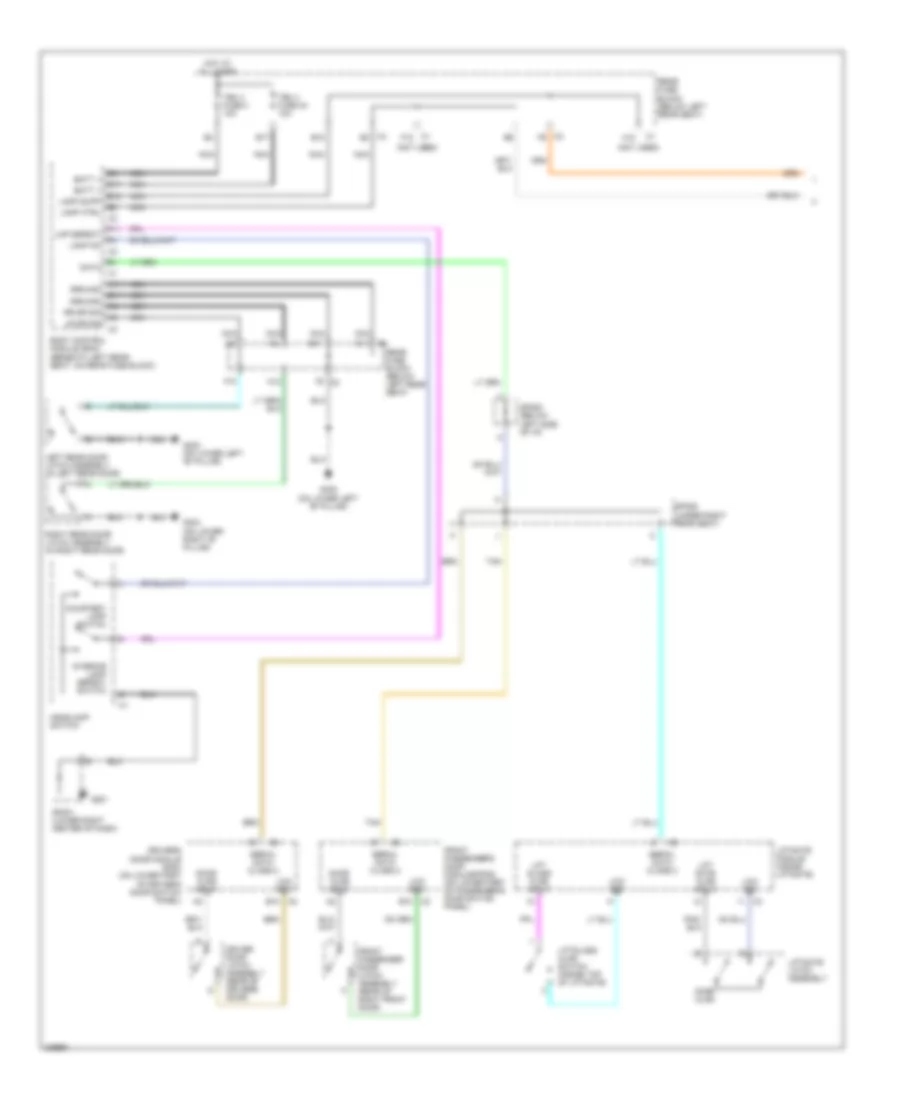
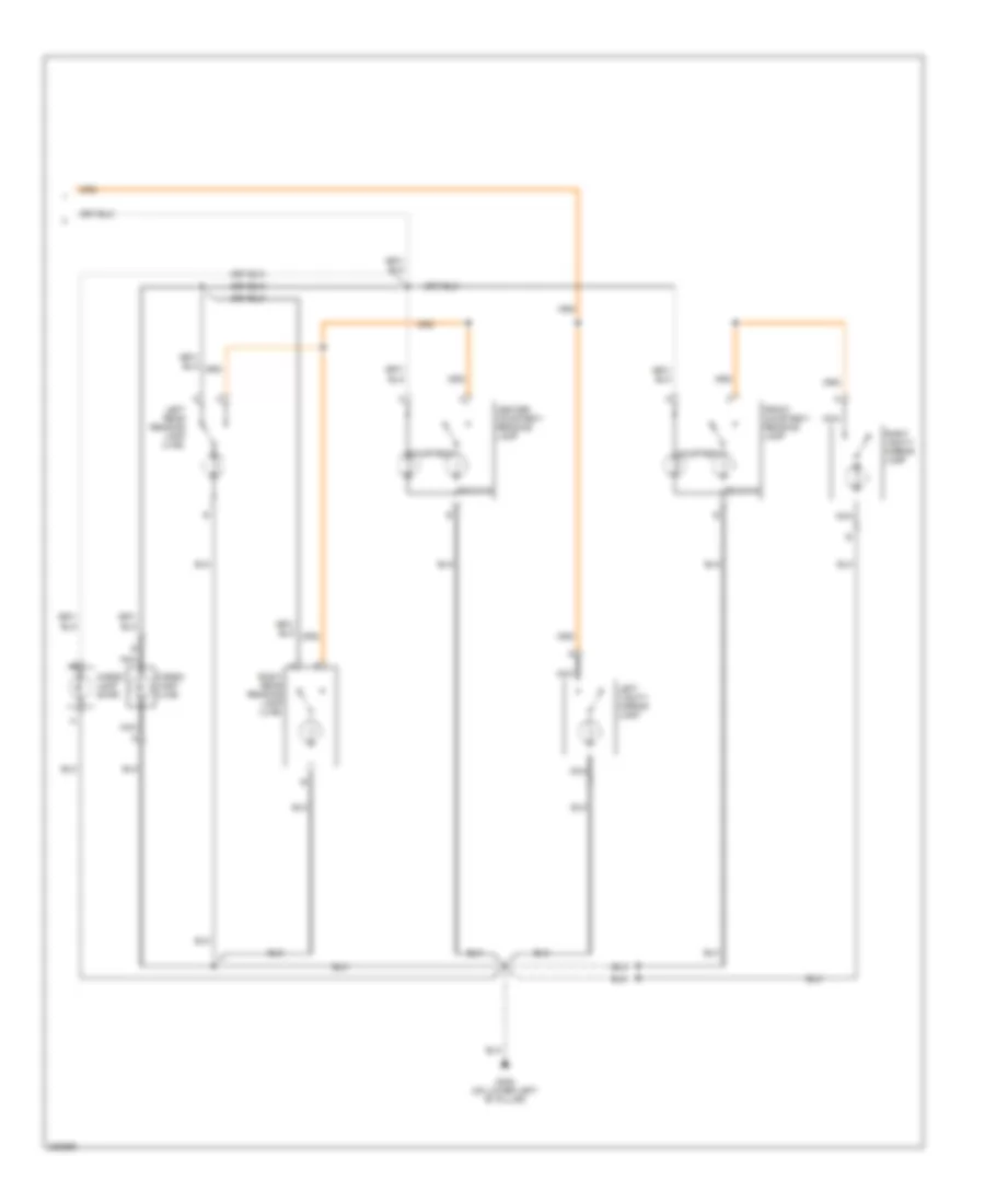
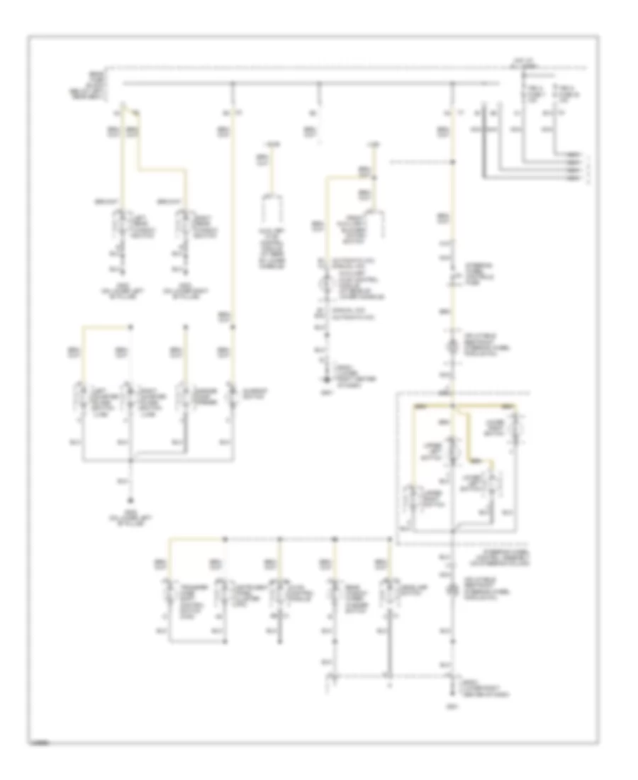
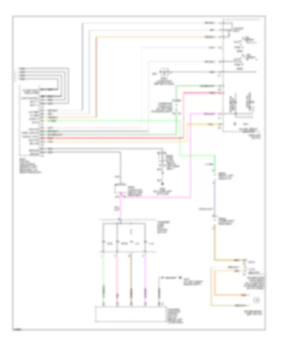
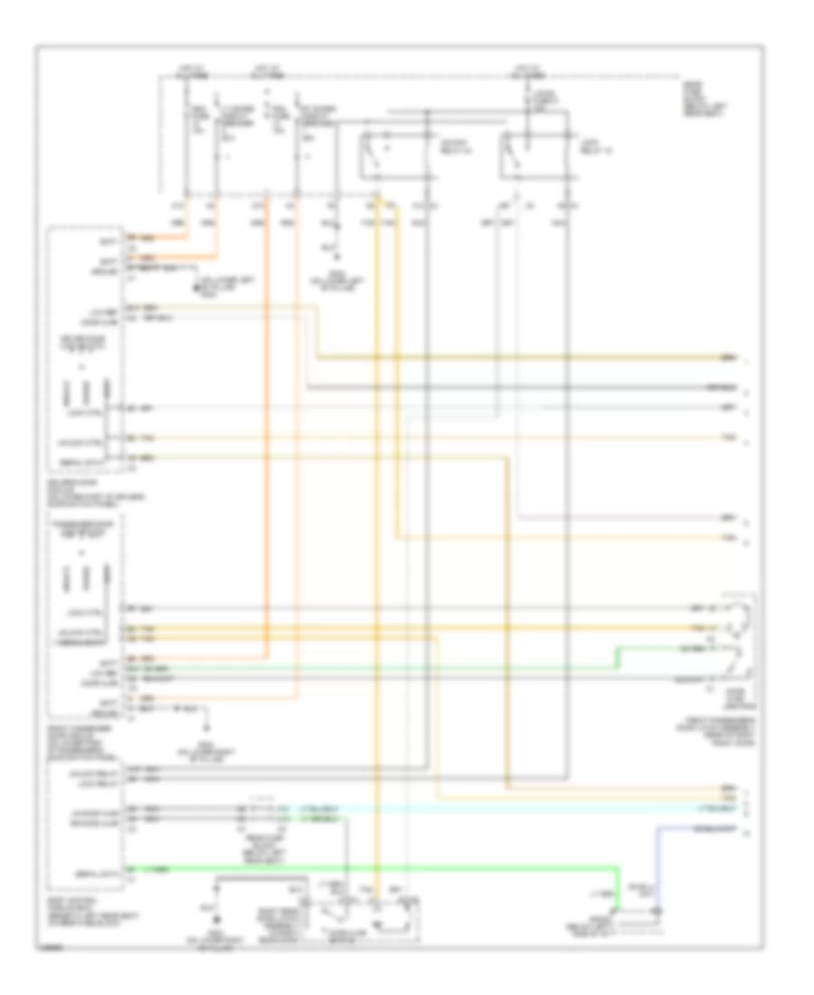
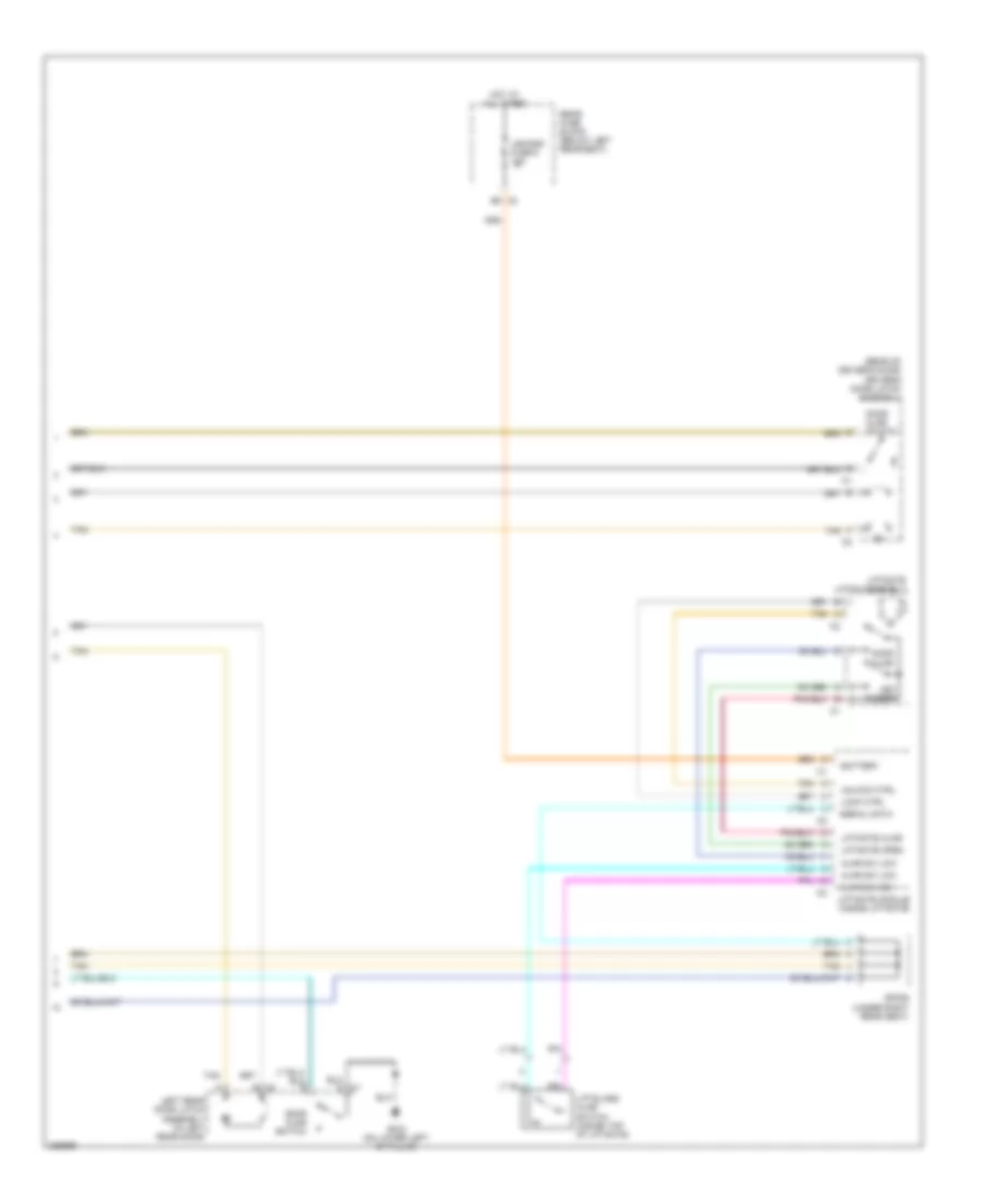
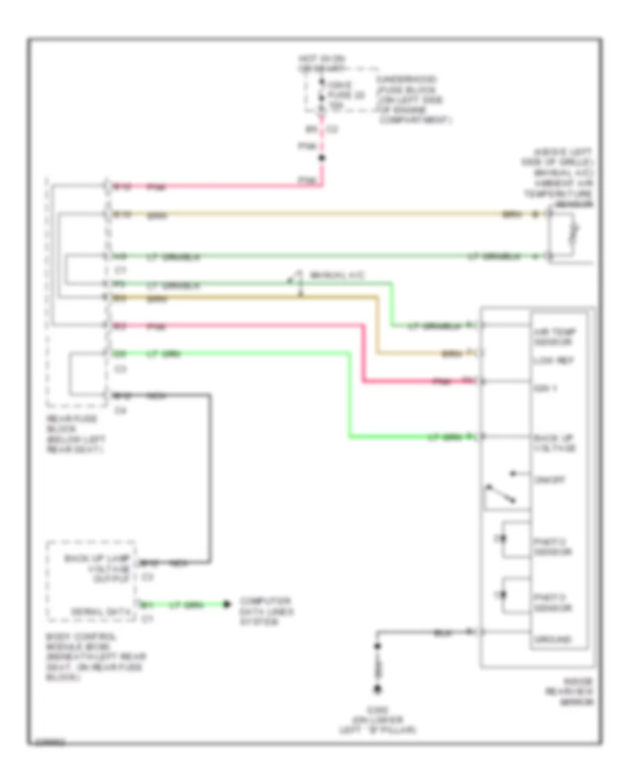
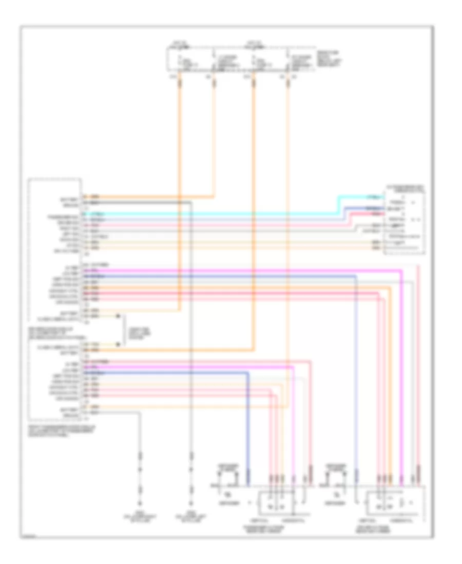
Diagram sections — 29 (78 total)
AIR CONDITIONING ANTI-LOCK BRAKES ANTI-THEFT BODY CONTROL MODULES COMPUTER DATA LINES COOLING FAN CRUISE CONTROL DEFOGGERS ENGINE PERFORMANCE EXTERIOR LIGHTS GROUND DISTRIBUTION HEADLIGHTS HORN INSTRUMENT CLUSTER INTERIOR LIGHTS MEMORY SYSTEMS POWER DISTRIBUTION POWER DOOR LOCKS POWER MIRRORS POWER SEATS POWER TOP/SUNROOF POWER WINDOWS RADIO SHIFT INTERLOCK STARTING/CHARGING SUPPLEMENTAL RESTRAINTS TRANSMISSION WARNING SYSTEMS WIPER/WASHER
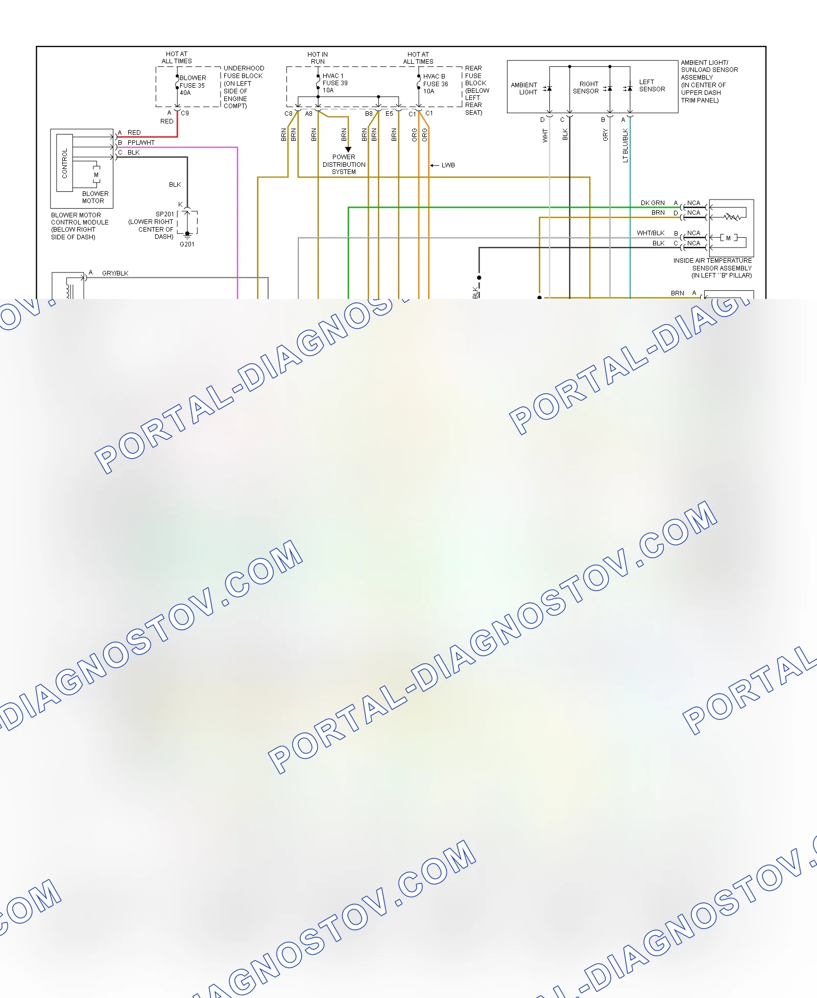
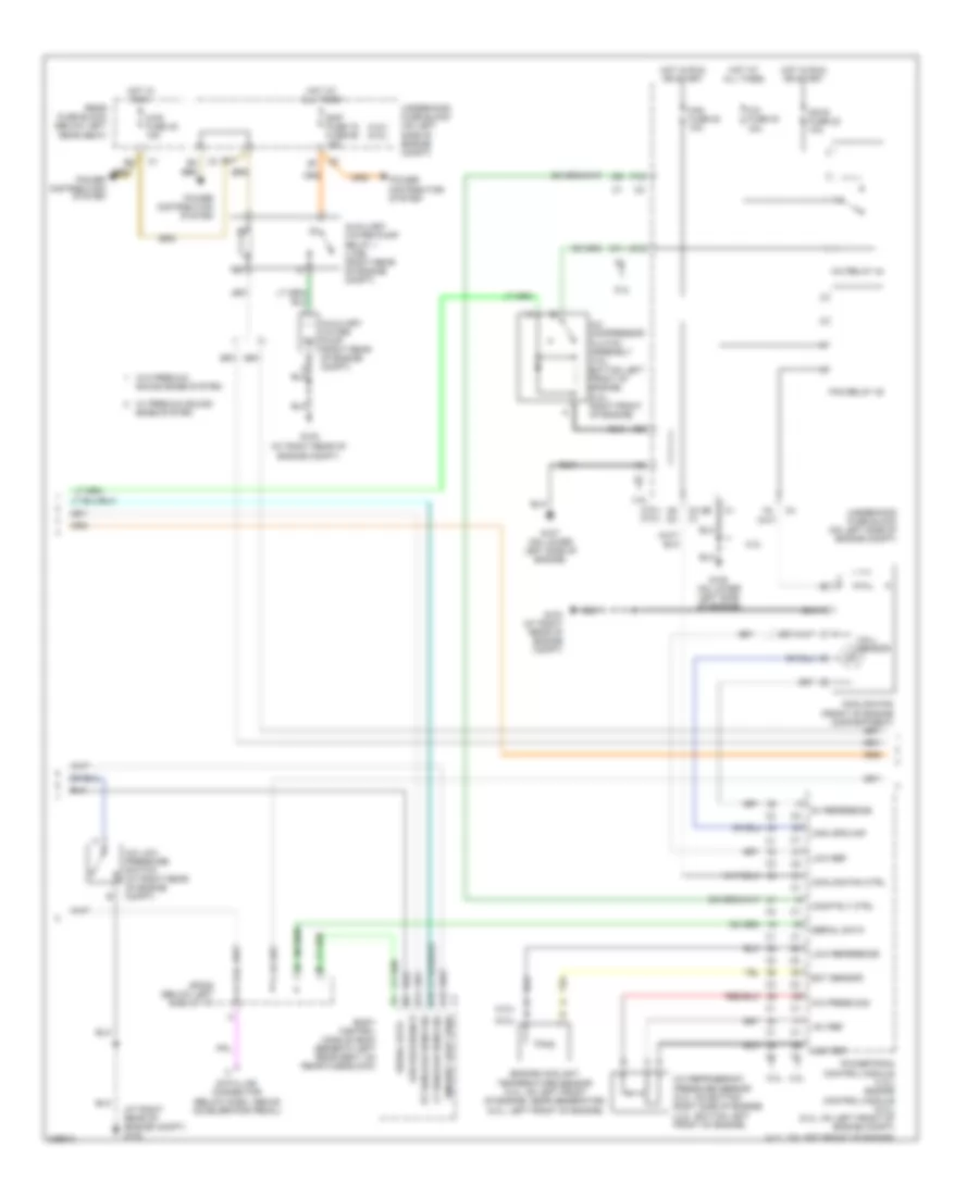
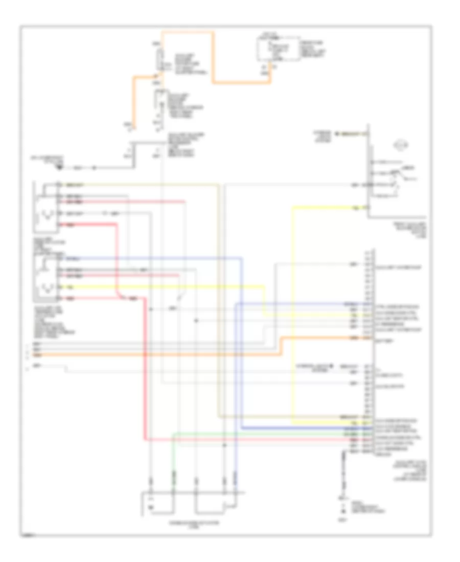
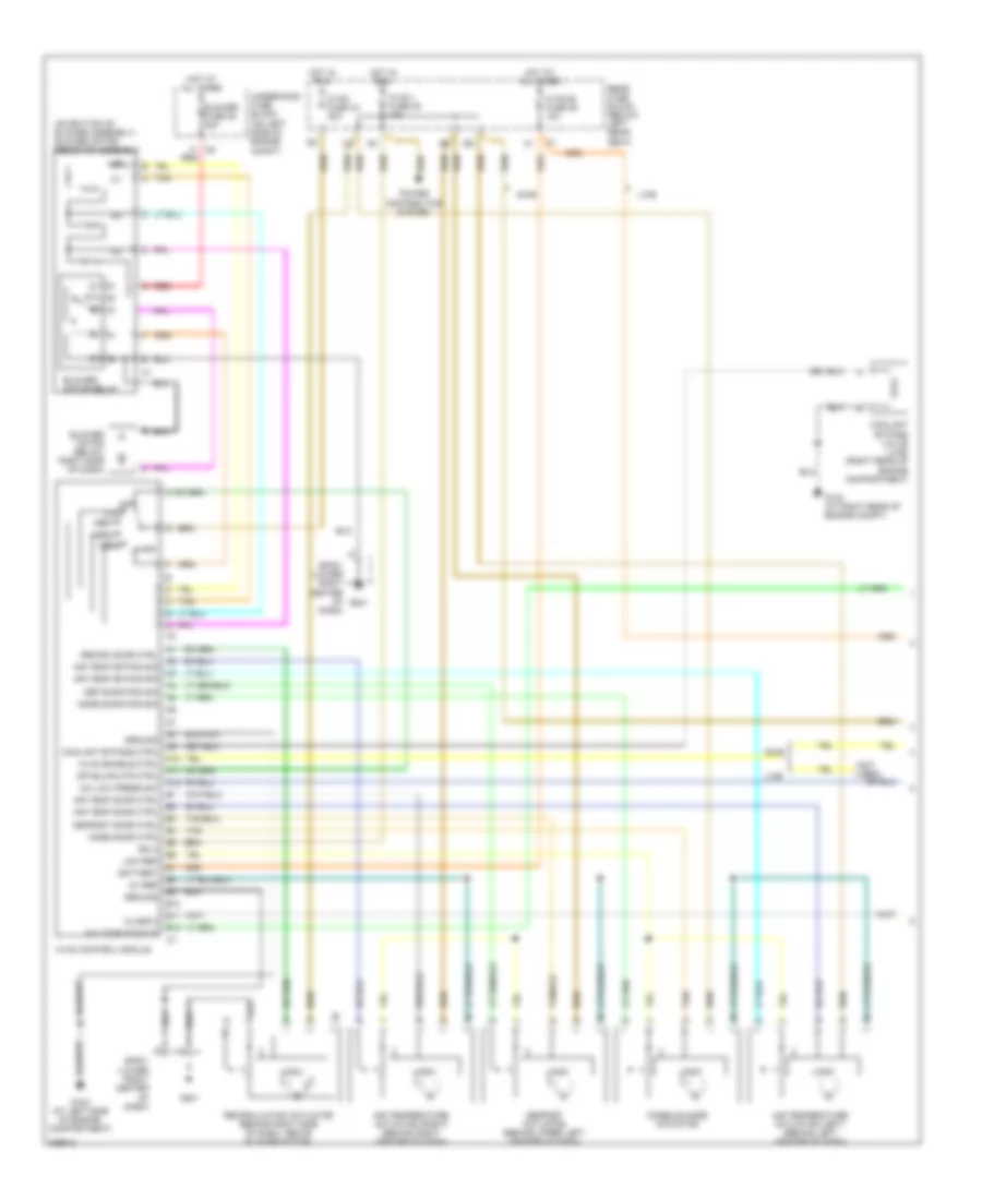
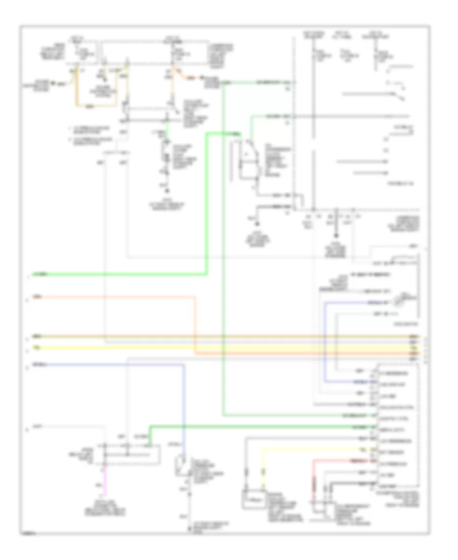
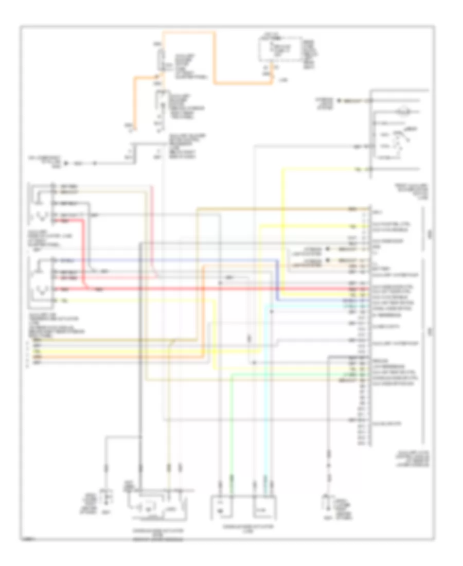
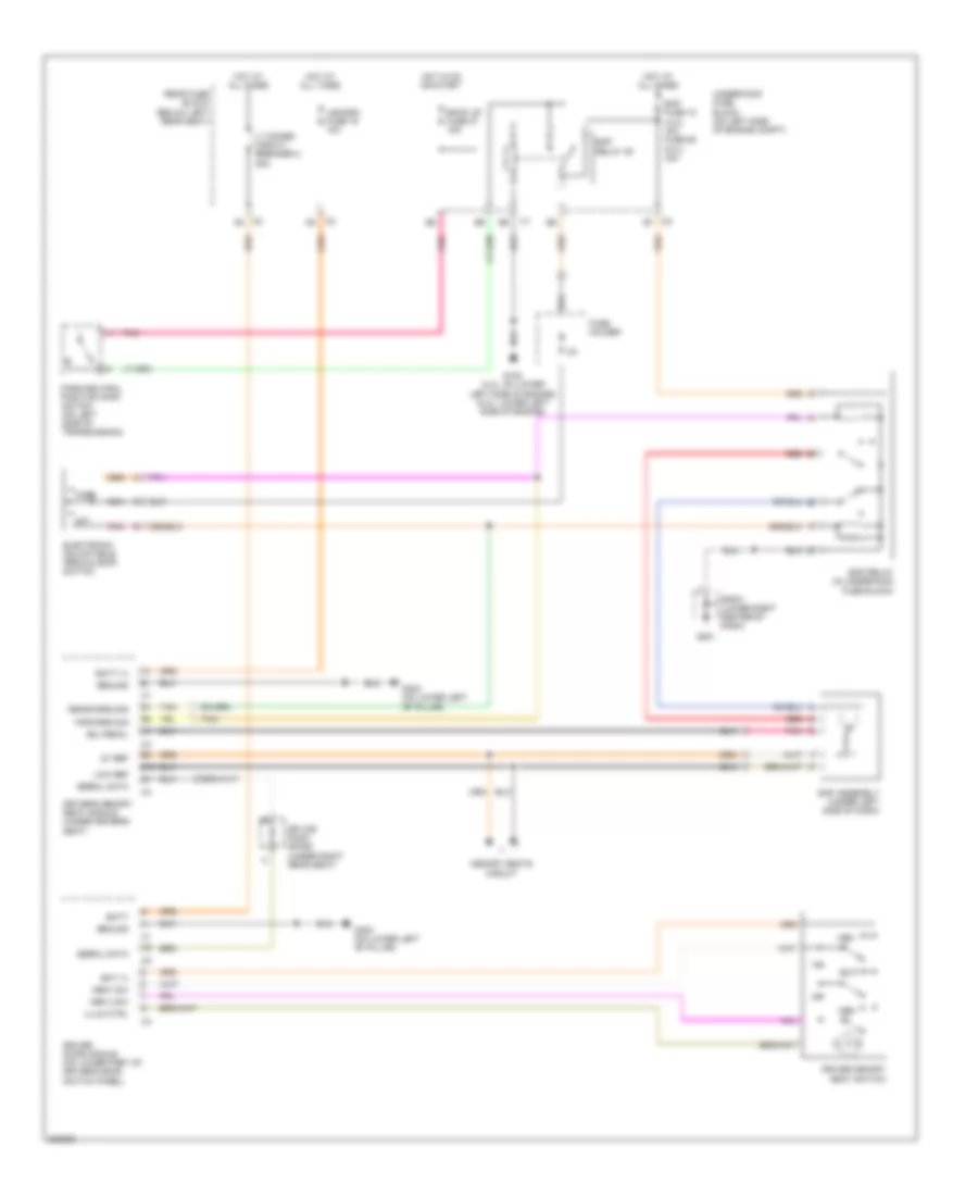
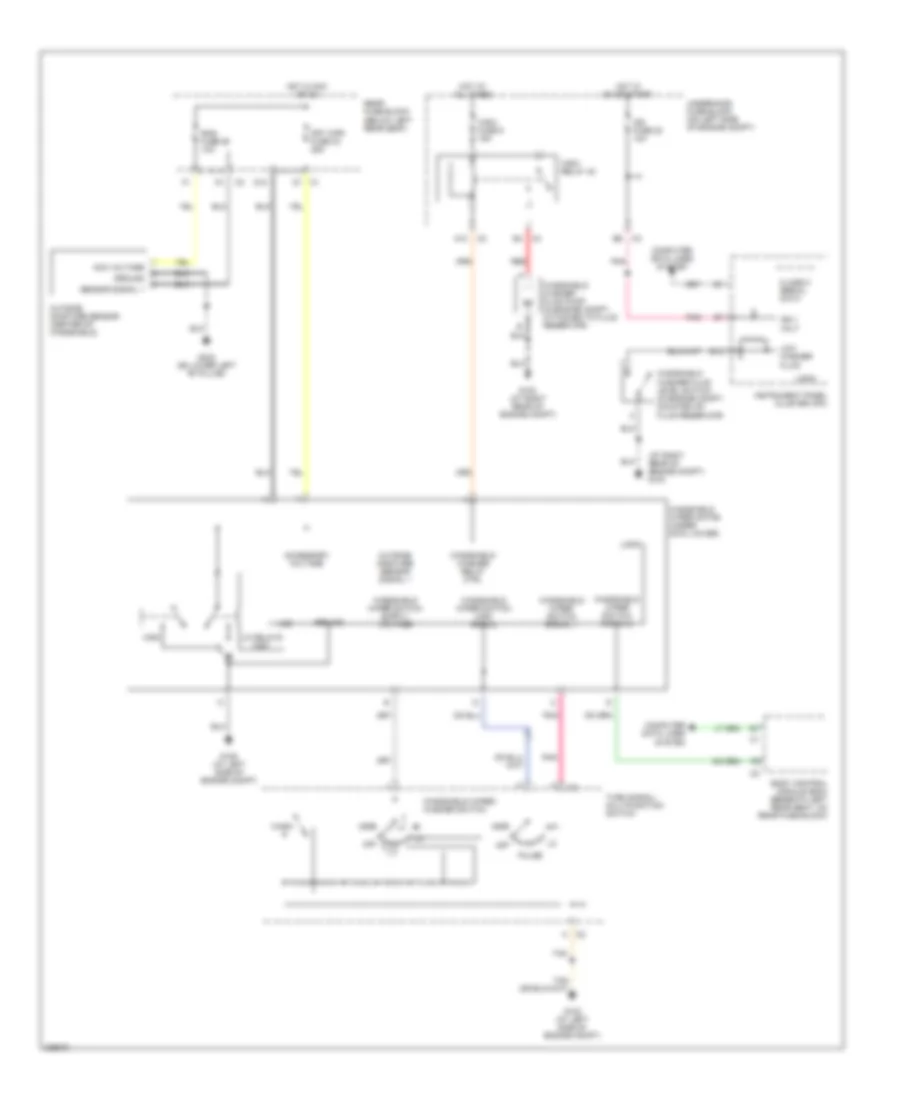
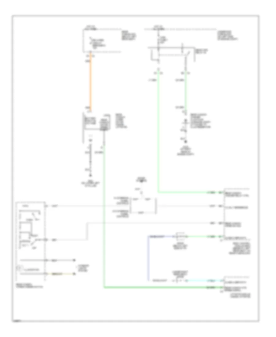
AIR CONDITIONING Automatic A/C Wiring Diagram (1 of 3) for Isuzu Ascender S 2006 List of elements for Automatic A/C Wiring Diagram (1 of 3) for Isuzu Ascender S 2006: 70 5v ref A/c comp status A/c low press sw A10 A11 A12 Air temp door ctrl Air temp dr pos sig Air temperature actuator (left) (behind left center of dash) Air temperature actuator (right) (behind right center of dash) Ambient air temp sig Ambient air temperature sensor (above left side of grille) Ambient light Ambient light/ sunload sensor assembly (in center of upper dash trim panel) B10 B11 B12 Battery Blower fuse 35 40a Blower motor Blower motor control module (below right side of dash) Blwr mtr spd ctrl Class 2 Control Coolant bypass ctrl Coolant bypass valve (lwb) (right rear of engine compartment) Def door pos sig Defrost actuator (behind upper left center of dash) Defrost door ctrl G102 (at left side of engine compartment) G103 (at right rear of engine compt) G201 G302 (on lower left ``b" pillar) Ground Hot at all times Hot in run Hvac 1 fuse 39 10a Hvac b fuse 36 10a Hvac control module Ign 3 Inside air temp ctrl Inside air temp sig Inside air temperature sensor assembly (in left ``b" pillar) Left sensor Low ref Low reference Lower left air temperature sensor (in lower left air duct assembly) Lower right air temperature sensor (in lower right air duct assembly) Lwb Lwr lt air temp sig Lwr rt air temp sig Mode actuator (behind upper left center of dash) Mode door ctrl Mode door pos sig Nca Power distribution system Rear fuse block (below left rear seat) Recirc door ctrl Recirc dr pos sig Recirculation actuator (behind right side of dash, above blower motor) Red Right sensor Solid state Sp201 (lower right center of dash) Tan Underhood fuse block (on left side of engine compt) Upper left air temperature sensor (in upper air duct) Upper right air temperature sensor (in upper air duct) Uppr lt air temp sig Uppr rt air temp sig Automatic A/C Wiring Diagram (2 of 3) for Isuzu Ascender S 2006 List of elements for Automatic A/C Wiring Diagram (2 of 3) for Isuzu Ascender S 2006: 62 (4.2l) (5.3l) (4.2l: on left front of engine) (5.3l) a (at right rear of engine compt) (at right rear of engine compt) g103 +5v ref 4.2l (4.2l) (5.3l) 4wd fuse 48 15a 5.3l 5.3l 4.2l 5v reference A/c compressor clutch assembly (4.2l: bottom left front of engine) (5.3l: right front of engine) A/c fuse 30 10a A/c low pressure switch (at right rear of engine compt) A/c press sig A/c refrigerant pressure sensor (5.3l: on bottom right side of engine) (4.2l: bottom left front of engine) A/c relay 44 A12 A5 d4 Ambient light sens Auxiliary water pump (right rear of engine compt) Auxiliary water pump relay 1 (lwb) (right rear of engine compt) B (4.2l) B11 B12 Body control module (bcm) (beneath left rear seat, on rear fuse block) C2 c1 Comp rly ctrl Cooling fan (front of engine compartment) Cooling fan ctrl D11 Data link connector (below dash, above accelerator pedal) E12 Eap fuse 15 fuse 59 15a Ect sensor Engine coolant temperature sensor (4.2l: on left front of engine, near generator) (5.3l: left front of engine) F12 Fan fuse 20 10a Fan relay 45 G103 G103 (at right rear of engine compt) G107 (on lower left side of engine) G108 (on lower left side of engine) Hall sensor High spd maf Hot at all times Hot in run Hot in run or start Ign e fuse 22 10a Low ref Low reference Lt sunload sens sig Power distribution system Power distribution system Powertrain control module (4.2l) engine control module (5.3l) (5.3l: on left front of engine compt) Rear fuse block (below left rear seat) Rt sunload sens sig Serial data Sp205 (below left side of i/p) Underhood fuse block (on left side of engine compt) W/ premium sound bose system W/o premium sound bose system Automatic A/C Wiring Diagram (3 of 3) for Isuzu Ascender S 2006 List of elements for Automatic A/C Wiring Diagram (3 of 3) for Isuzu Ascender S 2006: 49 (on lower right "d" pillar) g402 30a 5v reference A10 A11 A12 A13 A14 A15 A16 Aux act door ctrl Aux air temp dr ctrl Aux air temp dr pos Aux blwr mtr Aux hvac enable Aux mode door ctrl Aux mode dr pos sig Auxiliary air temperature actuator (lwb) (on rear hvac module, behind right rear interior body panel) Auxiliary blower motor (behind interior right rear trim panel) Auxiliary blower motor control processor (lwb) (below right side of dash) Auxiliary blower motor fuse (at right quarter panel) Auxiliary hvac control module (lwb) (at rear of lower console) Auxiliary mode actuator (lwb) (at right quarter panel) Auxiliary water pump B10 B11 B12 B13 B14 B15 B16 Battery Class 2 data Console mode actuator (lwb) Console mode dr ctrl Ctrl mode dr pos sig Front auxiliary blower motor switch (lwb) G201 Ground Hot at all times Ill Interior lights system Low reference Off Rear Rear fuse block (below left rear seat) Red Rr hvac fuse 13 30a (lwb) Sp201 (lower right center of dash) Manual A/C Wiring Diagram (1 of 3) for Isuzu Ascender S 2006 List of elements for Manual A/C Wiring Diagram (1 of 3) for Isuzu Ascender S 2006: 61 (not used) (on bottom of blower assembly) blower motor resistor assembly 5v ref 87a A red A/c comp status A/c low press sw A10 A11 A12 Air temp door ctrl Air temp dr pos sig Air temperature actuator (left) (behind left center of dash) Air temperature actuator (right) (behind right center of dash) B10 B11 B12 Battery Blower fuse 35 40a Blower motor (below right side of dash) Blower motor relay Class 2 Console mode actuator Coolant bypass ctrl Coolant bypass valve (lwb) (right rear of engine compartment) Def door pos sig Defrost actuator (behind upper left center of dash) Defrost door ctrl G102 (at left side of engine compartment) G103 (at right rear of engine compt) G201 Ground High Hot at all times Hot in run Hvac control module Hvac enable ctrl Hvac fuse 44 30a Hvac i fuse 39 10a Hvac-b fuse 36 10a Ign 3 Logic Low Low ref Lwb Med1 Med2 Med3 Mode door ctrl Mode door pos sig Off Off blwr mtr ctrl Power distribution system Rear fuse block (below left rear seat) Recirc door ctrl Recirculation actuator (behind right side of dash, above blower motor) Red Sp201 (lower right center of dash) Swb Tan Underhood fuse block (on left side of engine compt) Manual A/C Wiring Diagram (2 of 3) for Isuzu Ascender S 2006 List of elements for Manual A/C Wiring Diagram (2 of 3) for Isuzu Ascender S 2006: 47 (at right rear of engine compt) (at right rear of engine compt) g103 +5v ref 4wd fuse 48 15a 5v reference A/c compressor clutch assembly (bottom left front of engine) A/c fuse 30 10a A/c low pressure switch (at right rear of engine compt) A/c press sig A/c refrigerant pressure sensor (bottom left front of engine) A/c relay Auxiliary water pump (right rear of engine compt) Auxiliary water pump relay 1 (lwb) (right rear of engine compt) B11 Bose system Comp rly ctrl Cooling fan Cooling fan ctrl Data link connector (below dash, above accelerator pedal) E12 Eap fuse 15 15a Ect sensor Engine coolant temperature (ect) sensor (on left front of engine, near generator) F12 Fan fuse 20 10a Fan relay 45 G103 G103 (at right rear of engine compt) G107 (on lower left side of engine) G108 (on lower left side of engine) Hall sensor High spd maf Hot at all times Hot in run Hot in run or start Ign e fuse 22 10a Low ref Low reference Power distribution system Power distribution system Powertrain control module (pcm) (on left front of engine) Rear fuse block (below left rear seat) Serial data Sp205 (below left side of i/p) Underhood fuse block (on left side of engine compt) W/ premium sound W/o premium sound bose system Manual A/C Wiring Diagram (3 of 3) for Isuzu Ascender S 2006 List of elements for Manual A/C Wiring Diagram (3 of 3) for Isuzu Ascender S 2006: 59 (lwb) (not used) (on lower right ``d" pillar) g402 30a 5v reference A10 A11 A12 A13 A14 A15 A16 Auc hvac enable Aux act door ctrl Aux air temp dr ctrl Aux air temp dr pos Aux blwr mtr Aux mode door Aux mode door ctrl Aux mode dr pos sig Aux pump rel ctrl Auxiliary air temperature actuator (lwb) (on rear hvac module, behind right rear interior body panel) Auxiliary blower motor (behind interior right rear trim panel) Auxiliary blower motor control processor (lwb) (below right side of dash) Auxiliary blower motor fuse (at right quarter panel) Auxiliary hvac control module (at rear of lower console) Auxiliary mode actuator (at right quarter panel) Auxiliary water pump B10 B11 B12 B13 B14 B15 B16 Battery Class 2 data Consl mode dr pos Console mode actuator (lwb) Console mode actuator (swb) (rear of lower console) Console mode dr ctrl Front auxiliary blower motor switch (lwb) G201 Gnd Ground Hot at all times Ign 3 Ill Interior lights system Logic Low reference Lwb Off Rear Rear fuse block (below left rear seat) Red Rr hvac fuse 13 30a Sp201 (lower right center of dash) Swb
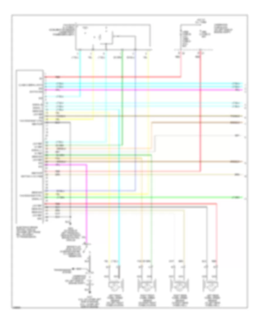
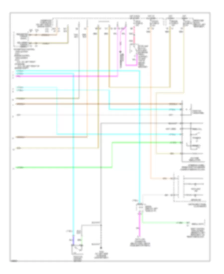
ANTI-LOCK BRAKES Anti-lock Brakes Wiring Diagram (1 of 2) for Isuzu Ascender S 2006 List of elements for Anti-lock Brakes Wiring Diagram (1 of 2) for Isuzu Ascender S 2006: 40 (in brake master (on left side of 5v ref Abs fuse 33 60a Abs pump Brake fluid Class 2 serial data Cylinder fluid Electronic brake control module (on inner left frame rail, adjacent to transmission) Engine compt) G107 (4.2l: on lower left side of engine) (5.3l: lower left side of engine) G304 (outside of left frame rail, near electronic brake control module) Gnd Hot at all times Ignition 3 voltage Left front wheel speed sensor (on left front wheelhousing) Left rear wheel speed sensor (in left rear wheelwell) Level switch Low ref Nca Red Reservoir) Right front wheel speed sensor (on right front wheelhousing) Right rear wheel speed sensor (in right rear wheelwell) Sens sig Sig Signal 1 Signal 2 Signal a Signal b Switch sig System Tan Transmissions Underhood fuse block Underhood fuse block (on left side of engine compt) Vses fuse 58 (4.2l) vses fuse 61 (5.3l) 60a Yaw rate & lateral acceleration sensor (under front passenger's seat) Yaw ring rast ctrl Yaw ring rastctrl Anti-lock Brakes Wiring Diagram (2 of 2) for Isuzu Ascender S 2006 List of elements for Anti-lock Brakes Wiring Diagram (2 of 2) for Isuzu Ascender S 2006: 50 (4.2l) (4.2l: on left front (5.3l) (5.3l: on left front of (not used) 4.2l 4.2l 5.3l 5.3l Anti-lock ind B10 B11 Body control module (bcm) (beneath left rear seat, on Brake fuse 51 10a Brake ind C1 a7 C1 b10 C11 Data link connector (below dash, above accelerator pedal) Delivered Engine compt) Engine control G102 (at left side of engine compartment) Hot at all times Hot in run Hot in run or start Hvac 1 fuse 39 10a Ign e fuse 22 10a Index pul Instrument panel cluster(ipc) Ipc/dic fuse 24 10a Module (ecm) Module (pcm) Of engine) Phase a Phase b Pnk Position handwheel Powertrain control Rear fuse block (below left rear seat) Rear fuse block) Requested Serial data Sp205 (below left side of i/p) Steering wheel/ speed position sensor (under steering column) Stoplamp switch (w/o eap: on brake pedal support) (w/ eap: top of brake pedal bracket) Torque signal Traction control switch Transmissions system Underhood fuse block (on left side of engine compt) Voltage regulator
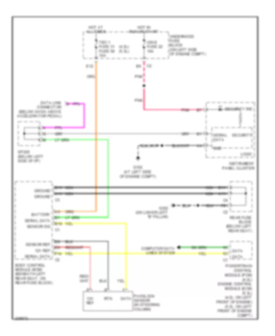
ANTI-THEFT Immobilizer Wiring Diagram for Isuzu Ascender S 2006 List of elements for Immobilizer Wiring Diagram for Isuzu Ascender S 2006: 35 (4.2l) (5.3l) 12v ref A11 B10 B11 Battery Body control module (bcm) (beneath left rear seat, on rear fuse block) Computer data lines system Data Data link connector (below dash, above accelerator pedal) E12 F14 G102 (at left side of engine compt) G302 (on lower left "b" pillar) Gnd Ground Hot at all times Hot in run or start Ign e fuse 22 10a Instrument panel cluster Logic Nca Passlock sensor (in steering column) Pnk Powertrain control module (pcm) (4.2l) engine control module (ecm) (5.3l) (4.2l: on left front of engine) (5.3l: on left front of engine compt) Rear fuse block (below left rear seat) Rtn Security Security ind Sensor ref Sensor sig Serial data Sp205 (below left side of i/p) Tbc 1 fuse 31 fuse 58 10a Underhood fuse block (on left side of engine compt)
BODY CONTROL MODULES
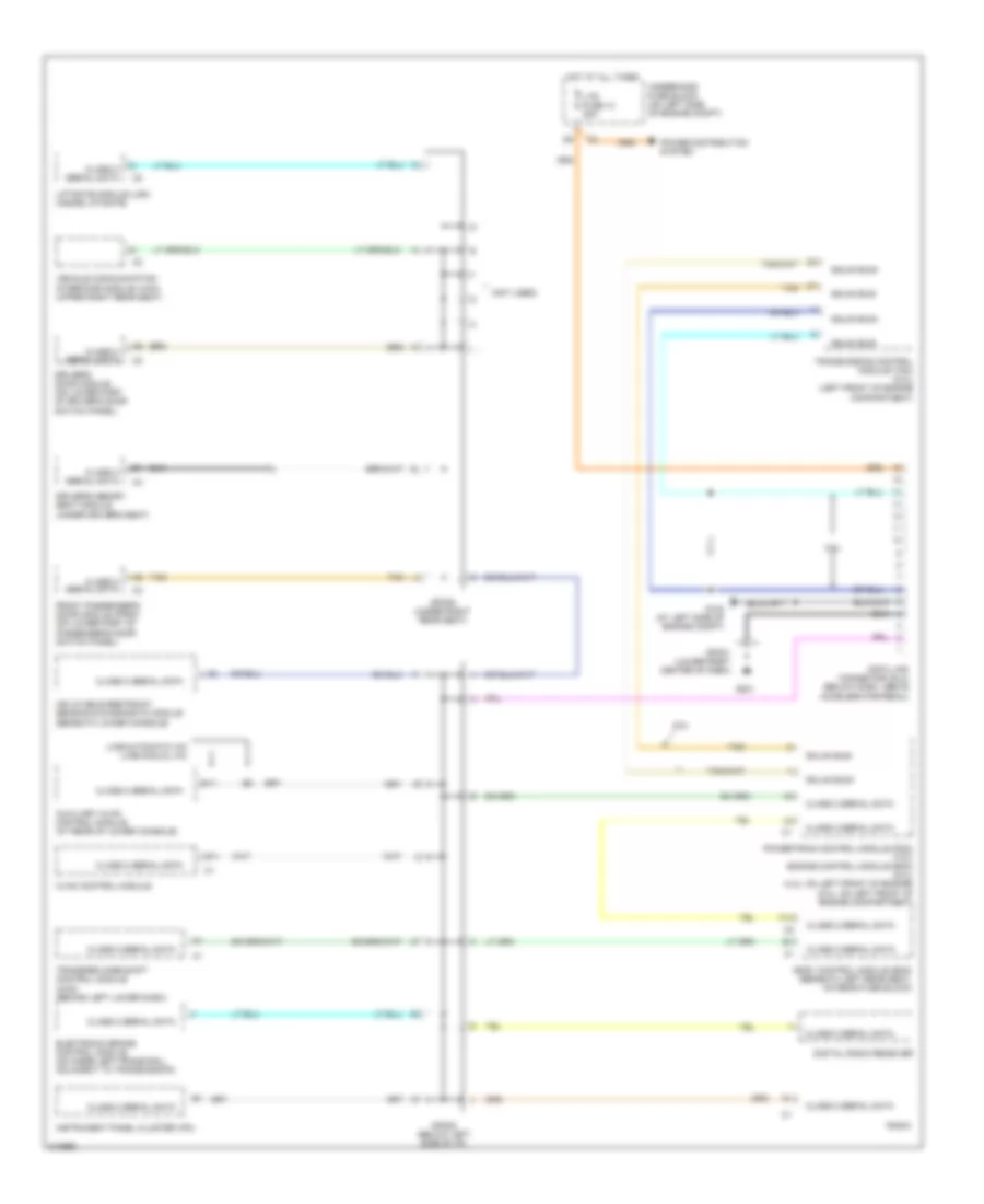
COMPUTER DATA LINES Computer Data Lines Wiring Diagram for Isuzu Ascender S 2006 List of elements for Computer Data Lines Wiring Diagram for Isuzu Ascender S 2006: 36 (not used) 5.3l A11 Auxiliary hvac control module (at rear of lower console) B11 Body control module (bcm) (beneath left rear seat, on rear fuse block) Class 2 serial data Data link connector (dlc) (below dash, above accelerator pedal) Digital radio receiver Driver's door module (on lower part of driver's door switch panel) Driver's memory seat module (under driver's seat) Electronic brake control module (on inner left frame rail, adjacent to transmission) F14 Front passenger's door module (fpdm) (on lower part of passenger's door switch panel) G102 (at left side of engine compt) G201 Gmlan bus+ Gmlan bus- Hot at all times Hvac control module Inflatable restraint sensing & diagnostic module (beneath lower console) Instrument panel cluster (ipc) Liftgate module (lgm) (inside liftgate) Ltr fuse 13 20a Lwb-automatic a/c lwb-manual a/c Power distribution system Powertrain control module (pcm) (4.2l) engine control module (ecm) (5.3l) (4.2l: on left front of engine) (5.3l: on left front of engine compartment) Radio Sp201 (lower right center of dash) Sp205 (below left side of i/p) Sp306 (under right rear seat) Tan Transfer case shift control module (4wd) (behind left lower dash) Transmission control module (tcm) (5.3l) (left front of engine compartment) Underhood fuse block (on left side of engine compt) Vehicle communication interface module (vcim) (upper right rear seat)
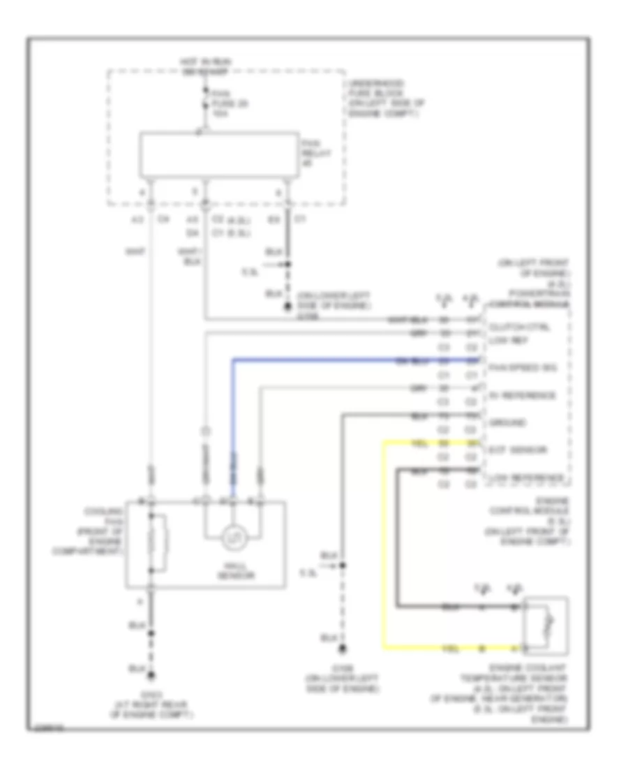
COOLING FAN Cooling Fan Wiring Diagram for Isuzu Ascender S 2006 List of elements for Cooling Fan Wiring Diagram for Isuzu Ascender S 2006: 23 (4.2l) (5.3l) (on left front of engine) (4.2l) powertrain control module (on lower left side of engine) g108 4.2l 5.3l 5v reference Clutch ctrl Cooling fan (front of engine compartment) Ect sensor Engine control module (5.3l) (on left front of engine compt) Engine coolant temperature sensor (4.2l: on left front of engine, near generator) (5.3l: on left front engine) Fan fuse 20 10a Fan relay Fan speed sig G103 (at right rear of engine compt) G108 (on lower left side of engine) Ground Hall sensor Hot in run or start Low ref Low reference Underhood fuse block (on left side of engine compt)
CRUISE CONTROL
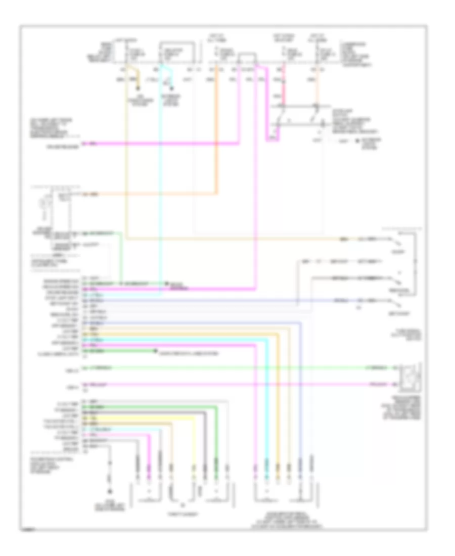
4.2L 4.2L, Cruise Control Wiring Diagram for Isuzu Ascender S 2006 List of elements for 4.2L, Cruise Control Wiring Diagram for Isuzu Ascender S 2006: 61 (on inner left frame rail, adjacent to transmission) electronic brake control module 5 volt ref A12 Accelerator pedal position (app) sensor (w/ eap: under left side of i/p) (w/o eap: on accelerator bracket) Air conditioning system App sensor 1 App sensor 2 B10 B4 c1 Batt volt C9 c2 Class 2 serial data Close Computer data lines system Cruise engaged ind Cruise release E1 c2 E3 c3 Engine spd sig Engine speed sig Exterior lights system G108 (on lower left side of engine) Ground Hot at all times Hot in run Hot in run or start Hvac 1 fuse 39 10a Ign e fuse 22 10a Instrument panel cluster (ipc) Ipc/dic fuse 24 10a Logic Low ref Nca On sw On/off Open Pnk Powertrain control module (pcm) (on left front of engine) Rear fuse block (below left rear seat) Res/accel Res/accel sw Set/coast Set/coast sw Sound systems St/lp fuse 12 25a Stop lamp input Stoplamp switch (w/o eap: on brake pedal support) (w/ eap: top of brake pedal bracket) Tac motor ctrl 1 Tac motor ctrl 2 Tan Throttle body Tp sensor 1 Tp sensor 2 Turn signal/ multi-function switch Underhood fuse block (on left side of engine compartment) Veh stop fuse 34 15a Vehicle spd sig Vehicle speed sensor (vss) (2wd: on right rear of transmission) (4wd: on left rear of transfer case) Vehicle speed sig Vss hi Vss lo
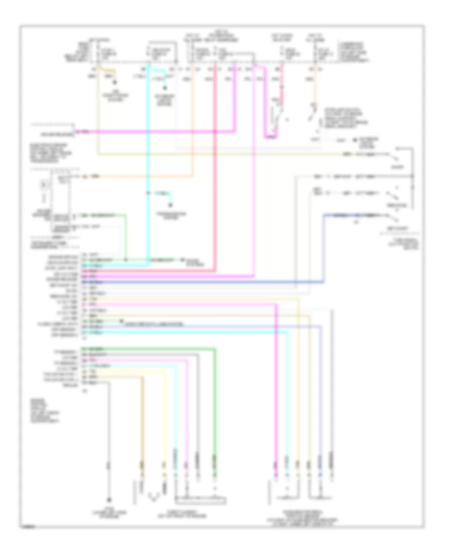
5.3L 5.3L, Cruise Control Wiring Diagram for Isuzu Ascender S 2006 List of elements for 5.3L, Cruise Control Wiring Diagram for Isuzu Ascender S 2006: 60 5 volt ref A12 Accelerator pedal position sensor (w/o eap: on accelerator bracket) (w/ eap: under left side of i/p) Air conditioning system App sensor 1 App sensor 2 B10 B4 c1 Batt volt C9 c2 Class 2 serial data Close Computer data lines system Cruise engaged ind Cruise release E1 c1 E1 c2 E3 c3 Electronic brake control module (on inner left frame rail, adjacent to transmission) Engine control module (on left front of engine compartment) Engine spd sig Exterior lights system G108 (lower left side of engine) Ground Hot at all times Hot in run or start Hot in run rear fuse block (below left rear seat) Hot w/ powertrain relay energized Hvac 1 fuse 39 10a Ign e fuse 22 10a Ign voltage Instrument panel cluster (ipc) Ipc/dic fuse 24 10a Logic Low ref Nca On sw On/off Open Pnk Res/accel Res/accel sw Set/coast Set/coast sw Sound systems St/lp fuse 12 25a Stop lamp input Stoplamp switch (w/o eap: on brake pedal support) (w/ eap: top of brake pedal bracket) Tac fuse 23 15a Tac motor ctrl 1 Tac motor ctrl 2 Tan Throttle body (on top front of engine) Tp sensor 1 Tp sensor 2 Transmissions system Turn signal/ multi-function switch Underhood fuse block (on left side of engine compartment) Veh stop fuse 34 15a Vehicle spd sig
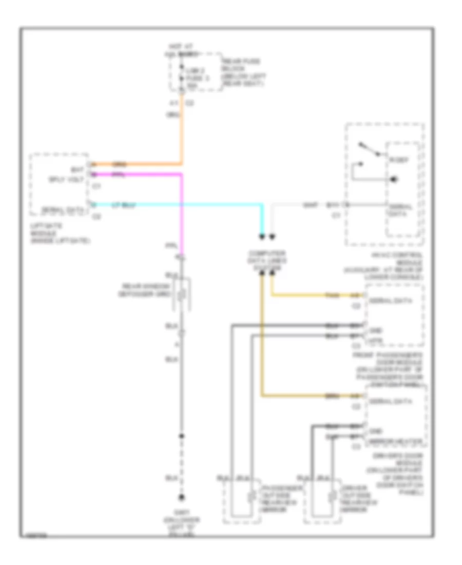
DEFOGGERS Defoggers Wiring Diagram for Isuzu Ascender S 2006 List of elements for Defoggers Wiring Diagram for Isuzu Ascender S 2006: 22 A1 c2 B11 Bat Computer data lines system Driver outside rearview mirror Driver's door module (on lower part of driver's door switch panel) Front passenger's door module (on lower part of passenger's door switch panel) G401 (on lower left "d" pillar) Gnd Hot at all times Htr Hvac control module (auxiliary: at rear of lower console) Lgm 2 fuse 3 30a Liftgate module (inside liftgate) Mirror heater Passenger outside rearview mirror R def Rear fuse block (below left rear seat) Rear window defogger grid Serial data Sply volt Tan
ENGINE PERFORMANCE
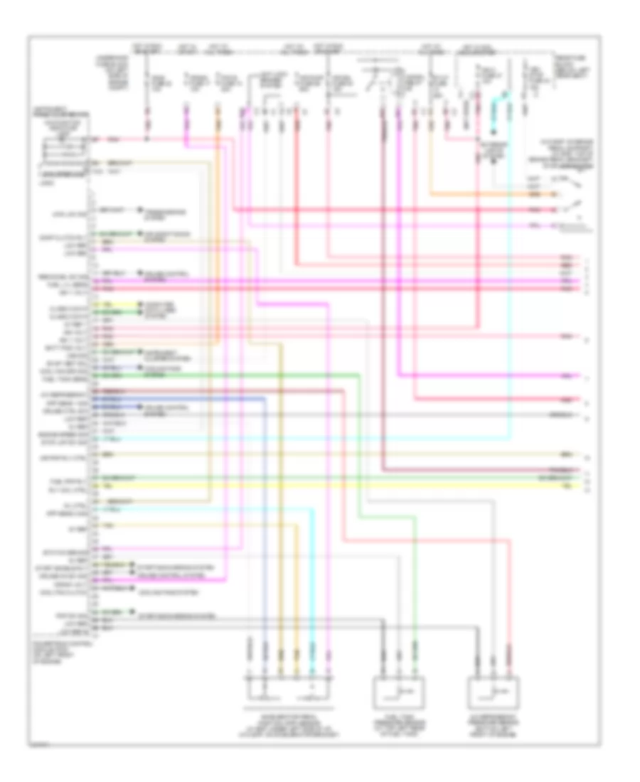
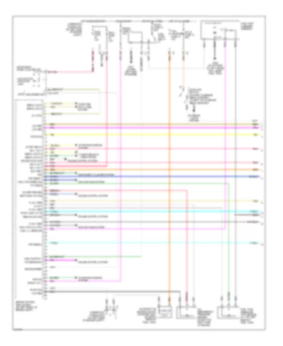
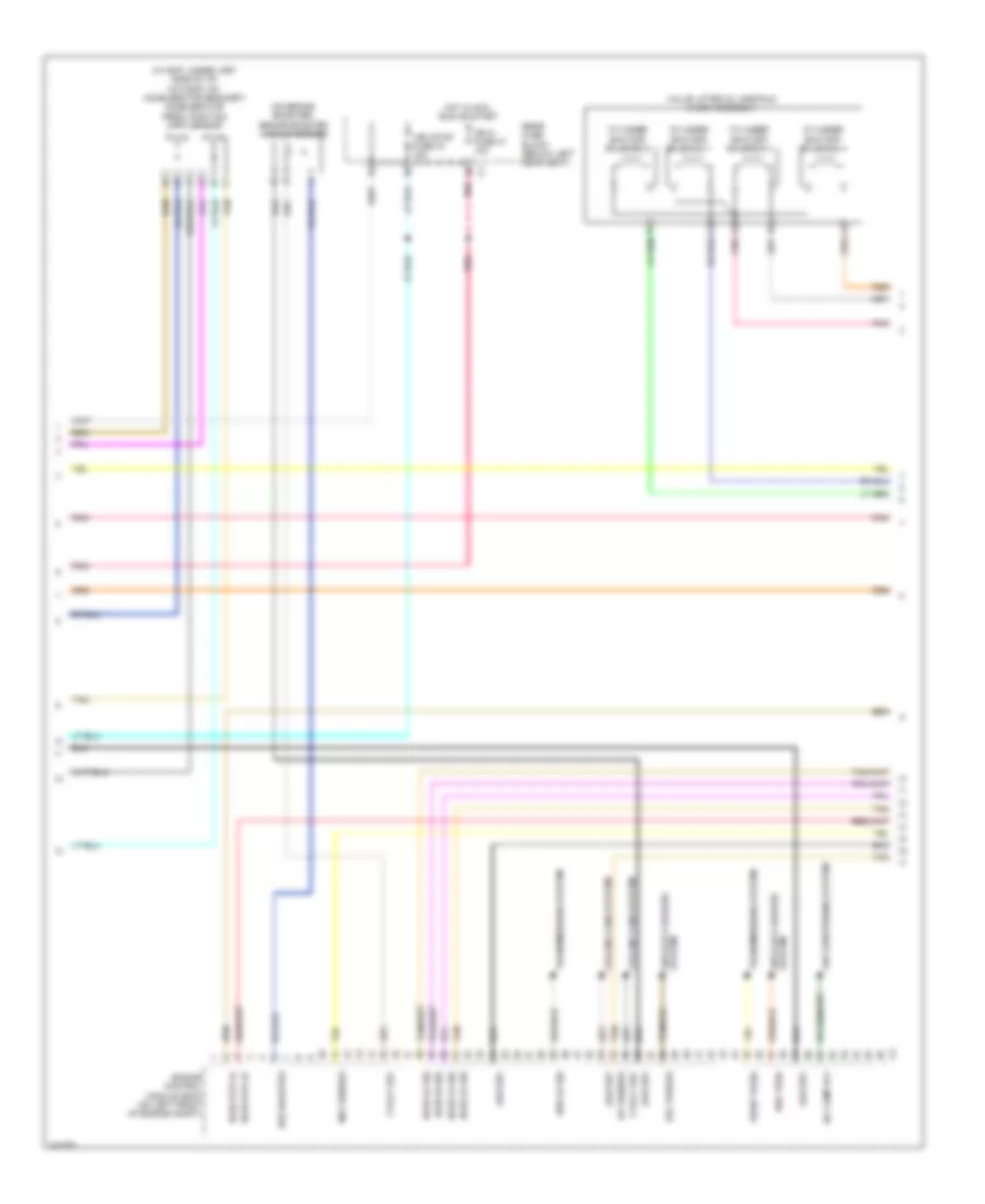
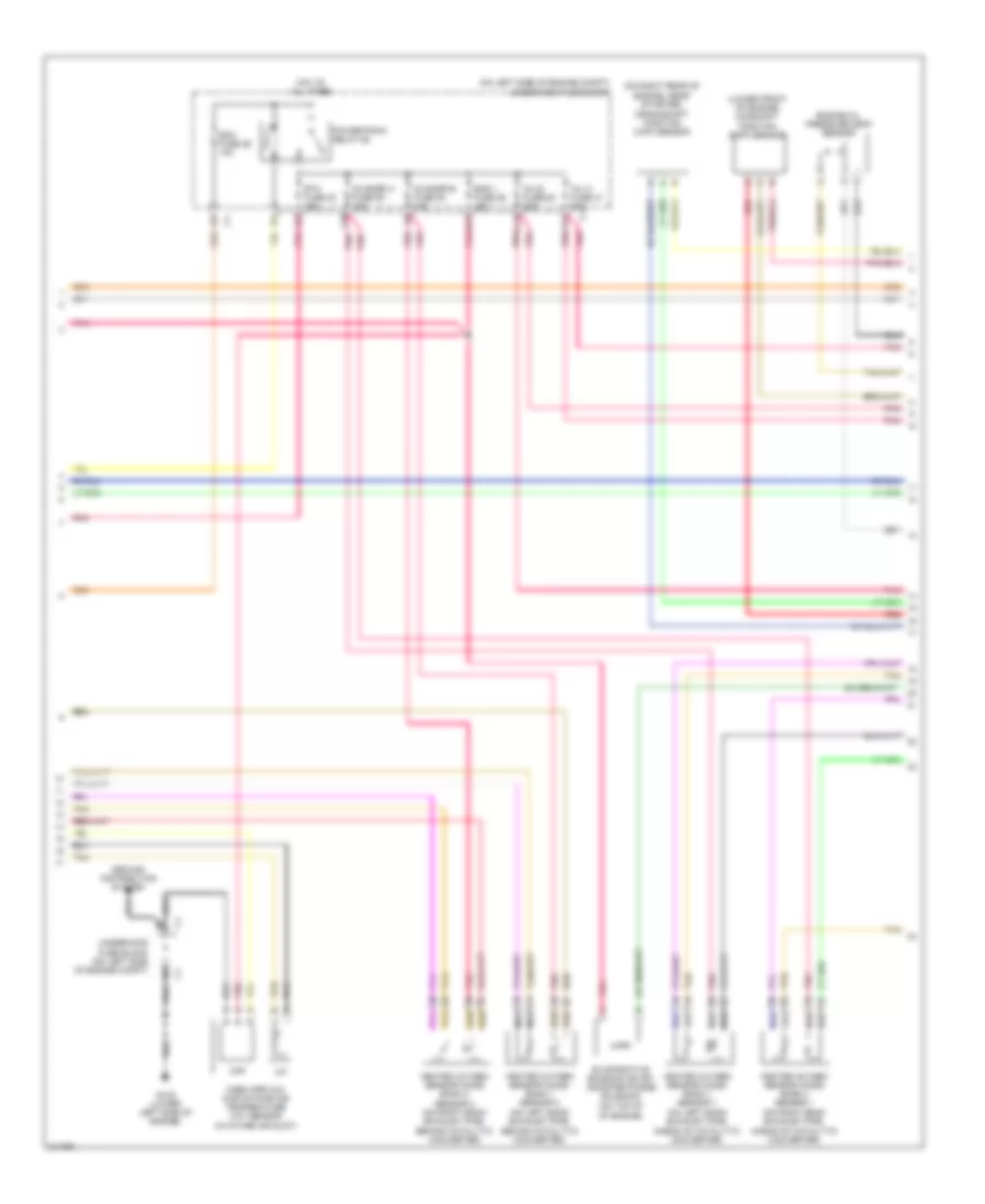
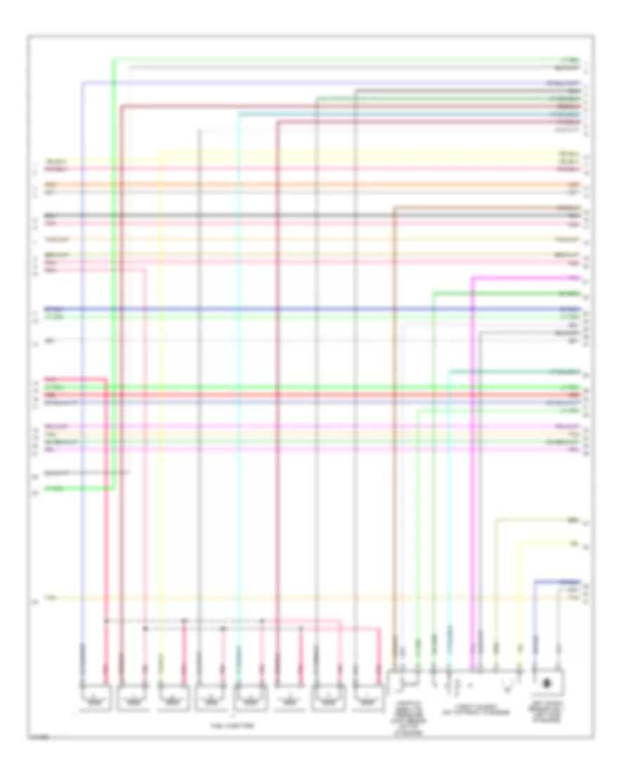
4.2L 4.2L, Engine Performance Wiring Diagram (1 of 5) for Isuzu Ascender S 2006 List of elements for 4.2L, Engine Performance Wiring Diagram (1 of 5) for Isuzu Ascender S 2006: 73 (not used) (w/o eap: on brake pedal support) (w/ eap: top of brake pedal bracket) stoplamp switch 4wd low sig 5v ref 5v ref 1 A/c refrigerant A/c refrigerant pressure sensor (bottom left front of engine) A12 Accelerator pedal position (app) sensor (w/ eap: under left side of i/p) (w/o eap: on accelerator bracket) Air conditioning system Air pmp rly ctrl Air pump fuse 56 60a Air sol fuse 54 15a Air sol relay Anti-lock brakes system App sens 1 sig App sens 2 sig B10 Batt pos volt Class 2 data Comp clutch rly Computer data lines system Cool fan clutch Cool fan spd sig Cooling fans system Crank fuse 17 10a Crank volt Cruise control system Cruise ctrl sw Cruise on sw sig D11 E11 Eng speed sig Engine speed sig Etc/tcc brk sig Evap vent sol Exterior lights system Fuel lvl sens Fuel pmp rly Fuel tank pressure sensor (at top left rear of fuel tank) Fuel tank sens Hot at all times Hot in acc, run or start Hot in run or start Hot in start Ign 1 volt Ign e fuse 22 10a Ign o fuse 47 10a Ign volt Instrument cluster system Instrument panel cluster (ipc) Logic Low ref Low ref b Malfunction indicator lamp Mil ctrl Pcm b fuse 10 20a Pnk Pnp sw sig Powertrain control module (pcm) (on left front of engine) Rear fuse block (below left rear seat) Red Res/accel sw sig Rly coil ctrl St/lp fuse 25a Start enable rly Starting/charging system Stop lmp sw sig Tan Transmissions system Underhood fuse block (on left side of engine compt) Veh stop fuse 34 15a Vss sig 4.2L, Engine Performance Wiring Diagram (2 of 5) for Isuzu Ascender S 2006 List of elements for 4.2L, Engine Performance Wiring Diagram (2 of 5) for Isuzu Ascender S 2006: 30 (on left frame rail, near ebcm) secondary air injection (air) pump (on left frame rail, near ebcm) secondary air injection (air) pump relay A red A11 C10 C11 Etc fuse 23 10a Evaporative emission (evap) canister purge solenoid (left side of engine) Evaporative emission canister vent solenoid (rear of fuel tank) Fuel pump & sender assembly Fuel pump relay G107 (on lower left side of engine) G305 (on outside of left frame rail, near fuel tank) Ground distribution system Heated oxygen sensor (ho2s) 1 (right side of engine, on exhaust manifold) Heated oxygen sensor (ho2s) 2 (in exhaust pipe, adjacent to transmission) Hot at all times Lwb Nca O2 snsr fuse 29 10a Pcm b fuse 10 20a Pnk Powertrain relay 57 Red Secondary air injection (air) solenoid (right rear of engine compt) Swb Tan Tcm cnstr fuse 26 10a Throttle body Underhood fuse block (on left side of engine compt) 4.2L, Engine Performance Wiring Diagram (3 of 5) for Isuzu Ascender S 2006 List of elements for 4.2L, Engine Performance Wiring Diagram (3 of 5) for Isuzu Ascender S 2006: 59 (in intake air duct) mass airflow (maf)/ intake air temperature (iat) sensor (on left front of engine) powertrain control module (pcm) (on left rear of engine, below starter) crankshaft position (ckp) sensor (on right front of cylinder head) camshaft position (cmp) sensor (on upper left side of engine) manifold absolute pressure (map) sensor 12v ref 5v ref 5v ref 1 Air sol rly ctrl Camshaft actuator solenoid assembly (on right front of cylinder head) Camshaft pos sol Charging system starting/ Ckp sig Cmp sens sig Cooling fans system Ect sens sig Engine coolant temperature (ect) sensor (on left front of engine, near generator) Front knock sensor (ks) 1 (on lower left front of engine block) Front knock sensor (ks) 2 (on lower left rear of engine block) Fuel inj 1 ctrl Fuel inj 2 ctrl Fuel inj 3 ctrl Fuel inj 4 ctrl Fuel inj 5 ctrl Fuel inj 6 ctrl G108 (on lower left side of engine) Gen field duty Gen turn on sig Ground Ground distribution system Hall effect sensor Ho2s hi sig b1 s1 Ho2s htr lo b1 s1 Ho2s lo sig b1 s1 Iat Iat sens sig Ign coil 1 ctrl Ign coil 2 ctrl Ign coil 3 ctrl Ign coil 4 ctrl Ign coil 5 ctrl Ign coil 6 ctrl Ks 1 sig Ks 2 sig Low ref Low ref b Maf Maf sens sig Map sens sig Pnk Powertrain control module (pcm) (on left front of engine) Red Starting/ charging system Tac mtr ctrl 1 Tac mtr ctrl 2 Tan Tp sens 1 sig Tp sens 2 sig Underhood fuse block (on left side of engine compt) 4.2L, Engine Performance Wiring Diagram (4 of 5) for Isuzu Ascender S 2006 List of elements for 4.2L, Engine Performance Wiring Diagram (4 of 5) for Isuzu Ascender S 2006: 29 (pc) solenoid valve pressure control (tcc) solenoid valve torque converter clutch 1-2 shift solenoid (1-2 ss) valve 2-3 shift solenoid (2-3 ss) valve 3-2 shift solnoid (3-2ss) valve Automatic transmission Automatic transmission fluid pressure manual valve position switch C10 D10 D2 switch D3 switch D4 switch E10 F10 Fluid temperature sensor automatic transmission Fuel injectors (left side of engine) G109 (on lower left side of of engine) Hot in run or start Ignition coils (top of engine) Lo switch Nca Pcm 1 fuse 28 15a Pnk Red Rev switch Spark plug Tan Torque converter clutch pulse width modulation (tcc pmw) solenoid valve Underhood fuse block (on left side of engine compt) 4.2L, Engine Performance Wiring Diagram (5 of 5) for Isuzu Ascender S 2006 List of elements for 4.2L, Engine Performance Wiring Diagram (5 of 5) for Isuzu Ascender S 2006: 35 1-2 shift sol ctrl 2-3 shift sol ctrl 3-2 sol vlv ctrl Air inj vlv 1 ctrl Anti-lock brakes system C1 underhood fuse block (on left side of engine compt) Deliver torque sig Engine oil pressure switch (on bottom right side of engine) Evap purge sol Fluid temp sens G108 (on lower left side of engine) Ground distribution system Ho2s hi b1 s2 Ho2s htr lo b1 s2 Low ref Oil pres sw sig Park/neutral position switch (on left side of transmission) Pc sol vlv ctrl Pc sol vlv hi ctrl Pnk Powertrain control module (pcm) (on left front of engine) Pres sw sig c Press sw sig a Red Req torque sig Tcc pwm sol vlv Tcc sol vlv ctrl Tfp sw sig b Trs sig a Trs sig b Trs sig c Trs sig p Vehicle speed sensor (2wd: on right rear of transmission) (4wd: on left rear of transfer case) Vss high sig Vss low sig
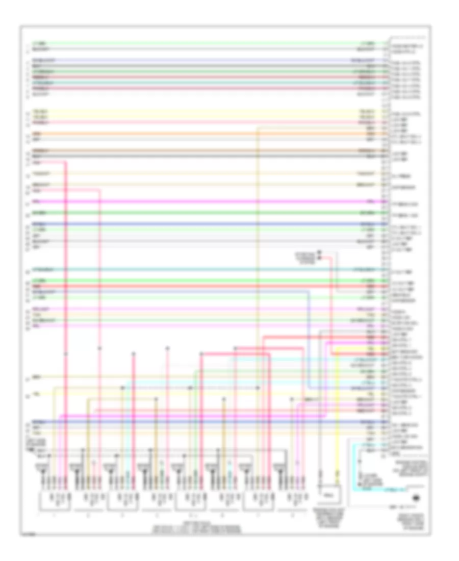
5.3L 5.3L, Engine Performance Wiring Diagram (1 of 5) for Isuzu Ascender S 2006 List of elements for 5.3L, Engine Performance Wiring Diagram (1 of 5) for Isuzu Ascender S 2006: 62 (not used) 5 volt 5 volt ref A/c ref pre sen A/c refrigerant pressure sensor (on bottom right side of engine) A12 App sens 1 App sens 2 Battery Computer data lines system Cool fan clu ctrl Cool fan speed sig Cooling fans system Crank fuse 17 10a Crank volt Cruise control system Cruise on sw sig Ecm 1 fuse 10a Eng speed sig Engine control module (ecm) (on left front of engine compt) Engine speed Evap can Evaporative emission (evap) canister vent solenoid (rear of fuel tank) Exterior lights system Ftp sens Fuel lvl sens sig Fuel pump & sender assembly Fuel pump relay Fuel pump rly Fuel tank pressure (ftp) sensor (at top left rear of fuel tank) G107 (lower left side of engine) G305 (on outside of left frame rail, near fuel tank) Hot at all times Hot in run or start Hot in start Ign 0 volt Ign 1 volt Ign e fuse 10a Instrument cluster system Instrument panel cluster (ipc) Logic Low ref Malfunction indicator lamp Mil ctrl Pcm b fuse 10 20a Pnk Pnp sw Pwr diag Res/acc sw sig Serial data Serial data 2 Set/coast sw sig St/lp fuse 12 25a Start relay Starting/charging system Stop lamp volts Stoplamp switch (w/o eap: on brake pedal support) (w/ eap: top of brake pedal bracket) Tan Tcc brake sw Tcm/ canister fuse 15 10a Underhood fuse block (on left side of engine compt) Vss 5.3L, Engine Performance Wiring Diagram (2 of 5) for Isuzu Ascender S 2006 List of elements for 5.3L, Engine Performance Wiring Diagram (2 of 5) for Isuzu Ascender S 2006: 31 (on brake booster) brake booster vacuum sensor (w/ eap: under lfet side of i/p) (w/o eap: on accelerator bracket) accelerator pedal position (app) sensor 4wd lo sig 5 volt ref A/c comp rly Air conditioning system Anti-lock brakes system Brk booster Cooling fans system Cylinder shutoff solenoid 1 Cylinder shutoff solenoid 2 Cylinder shutoff solenoid 3 Cylinder shutoff solenoid 4 Del torque Engine control module (ecm) (on left front of engine compt) Front hi sig Ho2s hi sig Ho2s htr lo Ho2s lo sig Hot in acc, run or start Iat sensor Ign o fuse 47 10a Low ref Maf sensor Pnk Rear fuse block (below left rear seat) Req torq Tan Transmissions system Valve lifter oil manifold (vlom) assembly Veh stop fuse 34 15a 5.3L, Engine Performance Wiring Diagram (3 of 5) for Isuzu Ascender S 2006 List of elements for 5.3L, Engine Performance Wiring Diagram (3 of 5) for Isuzu Ascender S 2006: 34 (lower front of engine) camshaft position (cmp) sensor (on left side of engine compt) underhood fuse block (on right rear of engine, near starter) crankshaft position (ckp) sensor (on top of of engine) A11 C11 Ecm fuse 29 10a Eng 1 fuse 26 15a Engine oil pressure (eop) sensor Etc fuse 23 15a Evaporative emission (evap) canister purge solenoid F10 F11 f11 G108 (lower left side of engine) Ground distribution system Heated oxygen sensor (ho2s) bank 1 sensor 1 (on left bank exhaust pipe, ahead of catalytic converter) Heated oxygen sensor (ho2s) bank 1 sensor 2 (on left bank exhaust pipe, behind catalytic converter) Heated oxygen sensor (ho2s) bank 2 sensor 1 (on right bank exhaust pipe, ahead of catalytic converter) Heated oxygen sensor (ho2s) bank 2 sensor 2 (on right bank exhaust pipe, behind catalytic converter) Hot at all times Iat Inj a fuse 31 20a Inj b fuse 56 20a Maf Mass airflow (maf)/intake air temperature (iat) sensor (in intake air duct) Nca O2 snsr a fuse 55 10a O2 snsr b fuse 54 10a Pnk Pnk pnk Powertrain relay 60 Red Tan Underhood fuse block (on left side of engine compt) 5.3L, Engine Performance Wiring Diagram (4 of 5) for Isuzu Ascender S 2006 List of elements for 5.3L, Engine Performance Wiring Diagram (4 of 5) for Isuzu Ascender S 2006: 7 Fuel injectors Left knock sensor (ks) 1 (left side of engine) Manifold absolute pressure (map) sensor (on top of engine) Pnk Red Tan Throttle body (on top front of engine) 5.3L, Engine Performance Wiring Diagram (5 of 5) for Isuzu Ascender S 2006 List of elements for 5.3L, Engine Performance Wiring Diagram (5 of 5) for Isuzu Ascender S 2006: 59 (left side of engine) g109 12 volt ref 5 volt ref Ckp sensor Cmp sensor Ctrl Cyl shut sol 1 Cyl shut sol 2 Cyl shut sol 3 Cyl shut sol 4 Ect sens sig Engine control module (ecm) (on left front of engine compt) Engine coolant temperature (ect) sensor (left front of engine) Evap can sol Fuel inj 1 ctrl Fuel inj 2 ctrl Fuel inj 3 ctrl Fuel inj 4 ctrl Fuel inj 5 ctrl Fuel inj 6 ctrl Fuel inj 7 ctrl Fuel inj 8 ctrl Gen field Gen turn on sig Gnd Ho2s heater lo Ho2s hi Ho2s hi sig Ho2s htr lo Ho2s low Ho2s low sig Ign Ign ctrl 1 Ign ctrl 2 Ign ctrl 3 Ign ctrl 4 Ign ctrl 5 Ign ctrl 6 Ign ctrl 7 Ign ctrl 8 Ignition coils (ign coils 1, 3, 5 & 7: top left side of engine) (ign coils 2, 4, 6 & 8: top right side of engine) Ks 1 sens sig Ks 2 sensor sig Low ref Map sensor Nca Nca nca Oil press Pnk Red Ref lo Right knock sensor (ks) 2 (right side of engine) Spark plug Starting/ charging system Tac mtr ctrl 1 Tac mtr ctrl 2 Tan Tp sens 1 sig Tp sens 2 sig
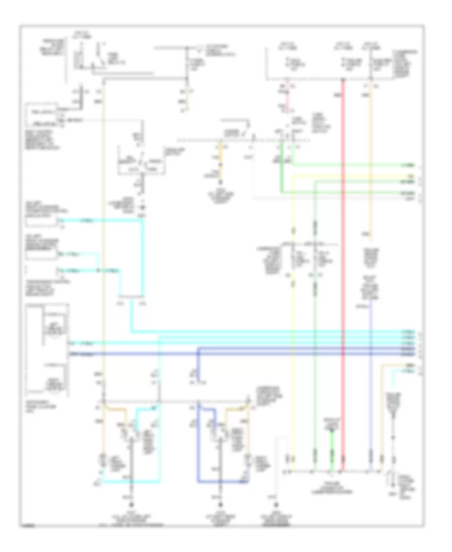
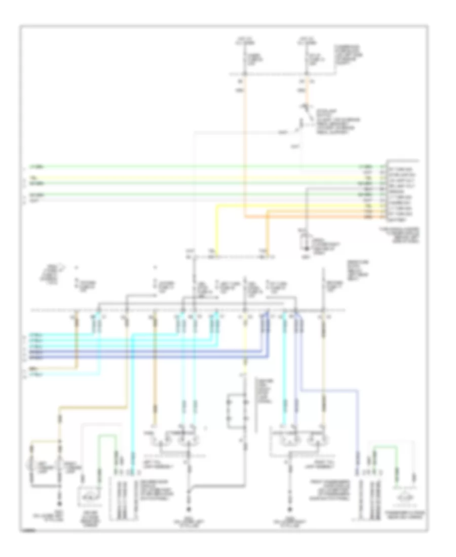
EXTERIOR LIGHTS Exterior Lamps Wiring Diagram (1 of 2) for Isuzu Ascender S 2006 List of elements for Exterior Lamps Wiring Diagram (1 of 2) for Isuzu Ascender S 2006: 52 (ipc) (on left front of engine) engine control module (ecm) (on left front of engine) powertrain control module (pcm) 4.2l 5.3l A10 A14 Auto Back-up lamps circuit Body control module (bcm) (beneath left rear seat, on rear fuse block) D10 Drl defeat Elek brk fuse 19 30a F park fuse 37 10a G102 (at left side of engine compt) G103 (at right rear of engine compt) G107 (4.2l: on lower left side of engine) (5.3l: lower left side of engine) G201 G403 (on left side of rear frame crossmember) Hazard switch Head Headlamp switch Hot at all times Ign e fuse 22 10a Instrument panel cluster Left Left front marker lamp Left front park/ turn signal lamp Left turn ind Nca Park Park lamp relay 30 Pnk Prk lmp on Prk lmp rly Rear fuse block (below left rear seat) Red Right Right front marker lamp Right front park/ turn signal lamp Right turn ind Sp201 (lower right center of dash) Tan To tr park fuse 42 (diagram 2 0f 2) Trailer connector (under rear bumper) Trailer fuse 32 30a Transmission control module (tcm) (left front of engine compt) Trl l trn fuse 51 10a Trl r trn fuse 50 10a Turn signal/ multi- function switch Turn switch Underhood fuse block (on left side of engine compt) Exterior Lamps Wiring Diagram (2 of 2) for Isuzu Ascender S 2006 List of elements for Exterior Lamps Wiring Diagram (2 of 2) for Isuzu Ascender S 2006: 45 Battery C2 f2 Center high mount stop lamp (chmsl) Driver outside rearview mirror Driver's door module (on lower part of driver's door switch panel) From a f park fuse 37 (diagram 1 0f 2) Front passenger's door module (on lower part of passenger's door switch panel) G201 G401 (on lower left "d" pillar) G402 (on lower right "d" pillar) Ground Hazard sw Hazrd fuse 52 25a Hot at all times Left license lamp Left tail lamp assembly Left turn fuse 38 10a Lr lamp volt Lr park fuse 14 10a Lt trn sig voltage Lt turn sig Mirror lt turn sig Mirror rt turn sig Park Passenger outside rearview mirror Rear fuse block (below left rear seat) Right license lamp Right tail lamp assembly Rr lamp volt Rr park fuse 17 10a Rt trn sig voltage Rt turn fuse 43 10a Rt turn sig Sp201 (lower right center of dash) St/lp fuse 12 25a Stop Stoplamp sw Stoplamp switch (w/ eap: top of brake pedal bracket) (w/o eap: on brake pedal support) Tan Tr park fuse 42 10a Turn Turn signal/hazard flasher module (behind left side of dash) Underhood fuse block (on left side of engine compt) Veh chmsl fuse 16 10a Veh stop fuse 34 15a
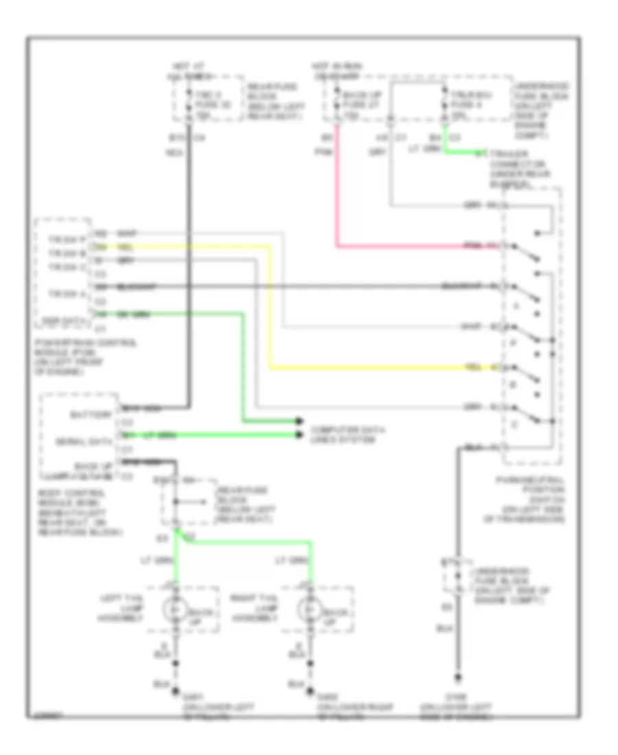
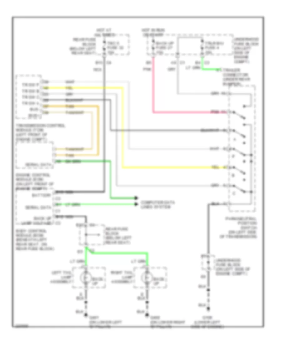
4.2L 4.2L, Back-up Lamps Wiring Diagram for Isuzu Ascender S 2006 List of elements for 4.2L, Back-up Lamps Wiring Diagram for Isuzu Ascender S 2006: 33 A trailer connector (under rear bumper) A9 c1 B12 B13 B13 c4 Back up Back up fuse 27 15a Back up lamp voltage c3 Battery Body control module (bcm) (beneath left rear seat, on rear fuse block) C3 b4 Computer data lines system G108 (on lower left side of engine) G401 (on lower left "d" pillar) G402 (on lower right "d" pillar) Hot at all times Hot in run or start Left tail lamp assembly Nca Park/neutral position switch (on left side of transmission) Pnk Powertrain control module (pcm) (on left front of engine) Rear fuse block (below left rear seat) Right tail lamp assembly Ser data Serial data Tbc 5 fuse 32 10a Tr sw a Tr sw b Tr sw c Tr sw p Trlr b/u fuse 4 10a Underhood fuse block (on left side of engine compt)
5.3L 5.3L, Back-up Lamps Wiring Diagram for Isuzu Ascender S 2006 List of elements for 5.3L, Back-up Lamps Wiring Diagram for Isuzu Ascender S 2006: 36 A trailer connector (under rear bumper) A9 c1 B12 B13 B13 c4 Back up Back up fuse 27 15a Back up lamp voltage c3 Battery Body control module (bcm) (beneath left rear seat, on rear fuse block) Bus+ Bus- C3 b4 Computer data lines system Engine control module (ecm) (on left front of engine compt) G108 (lower left side of engine) G401 (on lower left "d" pillar) G402 (on lower right "d" pillar) Hot at all times Hot in run or start Left tail lamp assembly Nca Park/neutral position switch (on left side of transmission) Pnk Rear fuse block (below left rear seat) Right tail lamp assembly Serial data Tan Tbc 5 fuse 32 10a Tr sw a Tr sw b Tr sw c Tr sw p Transmission control module (tcm) (left front of engine compt) Trlr b/u fuse 4 10a Underhood fuse block (on left side of engine compt)
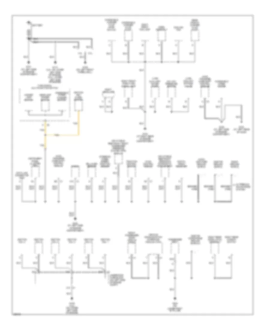
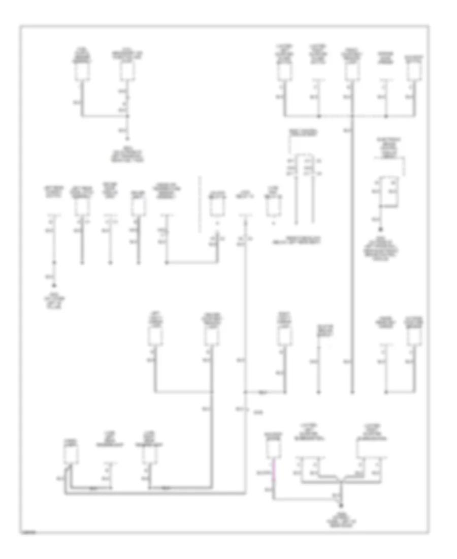
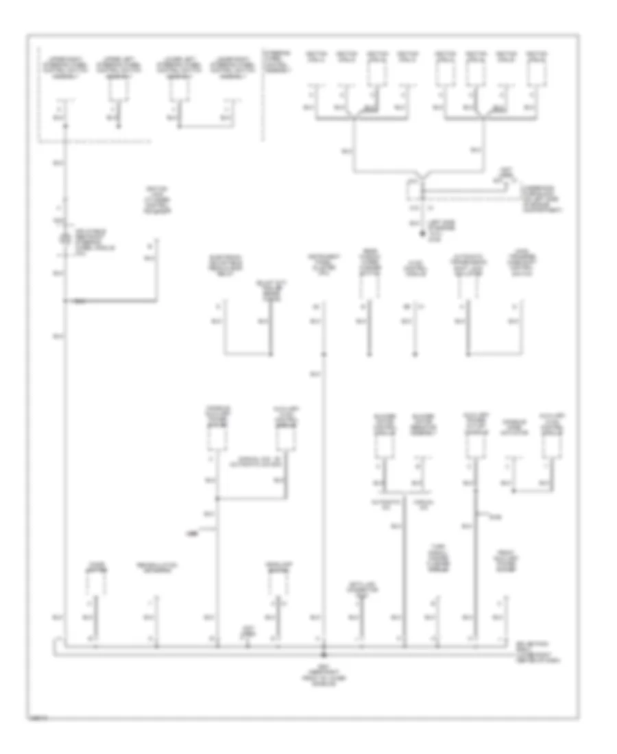
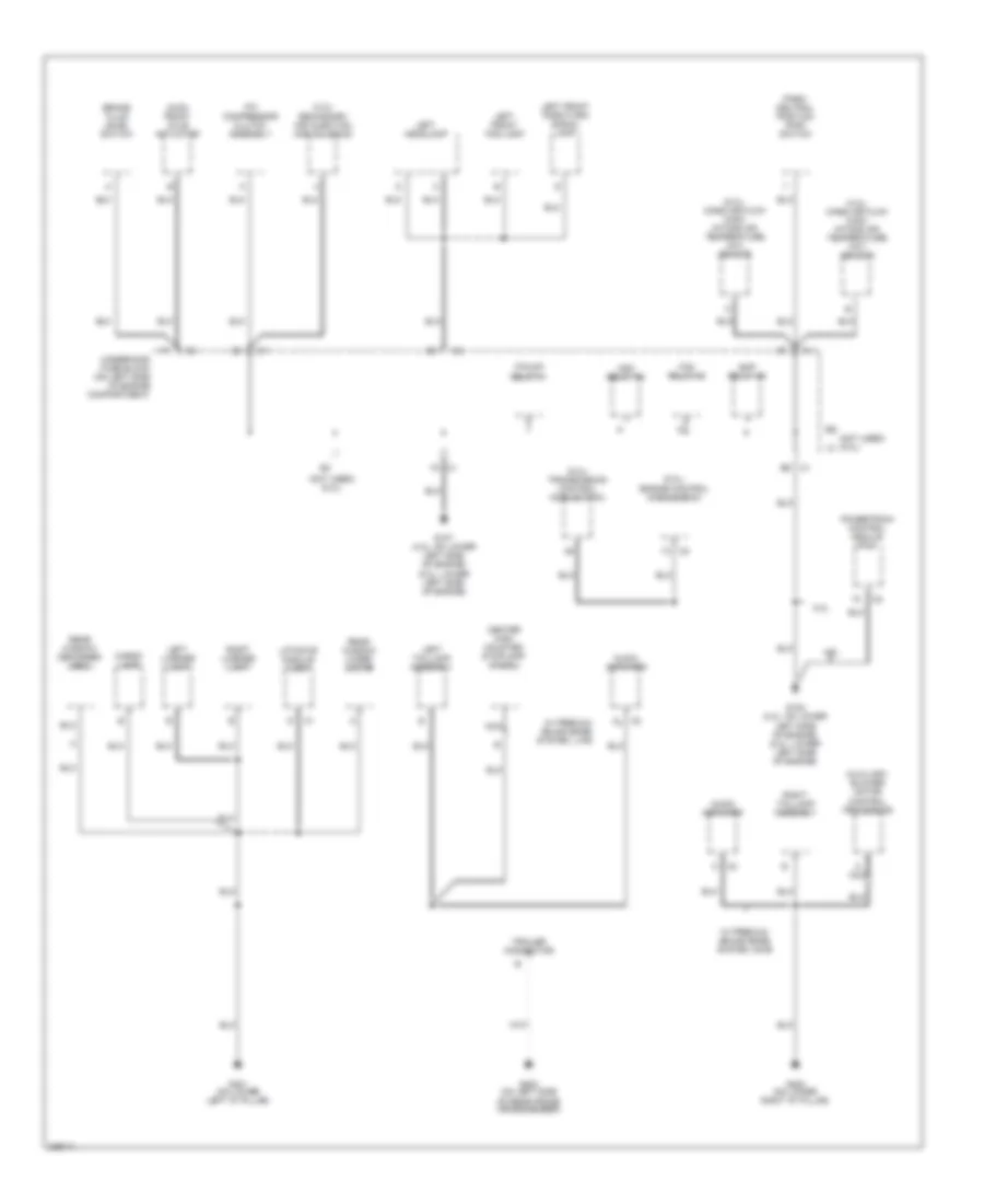
GROUND DISTRIBUTION Ground Distribution Wiring Diagram (1 of 4) for Isuzu Ascender S 2006 List of elements for Ground Distribution Wiring Diagram (1 of 4) for Isuzu Ascender S 2006: 66 (4wd) transfer case shift control module (lwb) (lwb) coolant bypass valve 4.2l 5.3l A/c low pressure switch A12 Audio amplifier ground shield Auxiliary water pump Battery Braided wire C10 Cooling fan D10 Data link connector (dlc) Digital radio receiver E10 F10 Front passenger door module (fpdm) G101 (at left side of engine compartment) G102 (at left side of engine compartment) G103 (at right rear of engine compartment) G104 (at left rear of hood) G105 (at left side of engine compartment) G106 (on left front wheelwell) G109 (4.2l) (on lower left side of engine) G110 (4.2l: on lower left side of engine) (5.3l: lower left side of engine) G303 (on lower right "b" pillar) Hazard lamp switch Headlamp dimmer switch Horn assembly Hvac control module Ignition coil 1 Ignition coil 2 Ignition coil 3 Ignition coil 4 Ignition coil 5 Ignition coil 6 Ignition key alarm switch Inflatable restraint front passenger presence system (pps) module Inflatable restraint sensing & diagnostic module (sdm) Instrument panel cluster (ipc) Nca Onstar ground shield Onstar microphone ground shield 2 Passenger seat Radio Radio ground shield Rear window washer fluid pump Right front fog lamp Right front park/turn signal lamp Right headlamp Right rear door latch assembly Right rear window switch Rollover sensor Steering wheel speed/ position sensor Tan Traction control switch Turn signal multifunction switch Underhood fuse block (on left side of engine compt) Vehicle communication interface module (vcim) W/ premium sound bose system Windshield washer fluid level switch Windshield washer fluid pump Windshield wiper motor Windshield wiper/ washer switch Ground Distribution Wiring Diagram (2 of 4) for Isuzu Ascender S 2006 List of elements for Ground Distribution Wiring Diagram (2 of 4) for Isuzu Ascender S 2006: 37 (4.2l) secondary air injection (air) pump (limited) left quarter glass switch (limited) right quarter glass switch (lwb) left rear reading lamp (lwb) rap relay 22 (lwb) right rear reading lamp A11 B11 Body control module (bcm) Cargo lamp Center courtesy/ reading lamp Driver door module (ddm) Driver seat Electronic brake control module (ebcm) Front courtesy/ reading lamp Fuel pump & sender assembly G302 (on lower G304 (outside of left frame rail, near electronic brake control module) G305 (on outside of left frame rail, near fuel tank) G306 (on body panel, left of rear door) Garage door opener Inside air temperature sensor assembly Inside rearview mirror Left "b" pillar) Left rear door latch assembly Left rear window switch Left vanity mirror lamp Lock relay 18 Nca On star ground shield 1 Outside moisture sensor Rear fuse block (below left rear seat) Right vanity mirror lamp Sun roof motor Sun roof switch Swb Unlock relay 24 Ground Distribution Wiring Diagram (3 of 4) for Isuzu Ascender S 2006 List of elements for Ground Distribution Wiring Diagram (3 of 4) for Isuzu Ascender S 2006: 50 (4wd) transfer case shift control switch (5.3l) (left side of engine) (manual a/c) (automatic a/c) (not used) Automatic a/c Automatic transmission shift lock actuator Auxiliary hvac control module Auxiliary power outlet console B1 b16 Blower motor control module Blower motor resistor assembly C10 Cigar lighter Console auxiliary power outlet Console mode actuator D10 Data link connector (dlc) E10 Electronic adjustable pedals (eap) relay Front auxiliary power outlet G109 G201 (near right front of lower console) Headlamp switch Hvac control module Ignition coil 1 Ignition coil 2 Ignition coil 3 Ignition coil 4 Ignition coil 5 Ignition coil 6 Ignition coil 7 Ignition coil 8 Ignition lock cylinder control actuator Inflatable restraint steering wheel module coil Instrument panel cluster (ipc) Lower left steering wheel control switch assembly Lower right steering wheel control switch assembly Lwb lwb lwb lwb Manual a/c Nca Rear window wiper/ washer switch Recirculation actuator Splice pack sp201 (lower right center of dash) Steering wheel control assembly Swb Turn signal/ hazard flasher module Underhood fuse block (on left side of engine compartment) Upper left steering wheel control switch assembly Upper right steering wheel control switch assembly Ground Distribution Wiring Diagram (4 of 4) for Isuzu Ascender S 2006 List of elements for Ground Distribution Wiring Diagram (4 of 4) for Isuzu Ascender S 2006: 43 (4.2l) mass air flow (maf)/ intake air temperature (iat) sensor (4.2l) secondary air injection (air) solenoid (4wd) front axle actuator (5.3l) engine control module (ecm) (5.3l) mass air flow (maf)/ intake air temperature (iat) sensor (5.3l) transmission control module (tcm) (not used) (5.3l) 4.2l 5.3l A nca A/c compressor clutch assembly Audio amplifier Auxiliary blower motor control processor Brake fluid level switch Cargo lamp Center high mounted stoplamp (chmsl) E6 c1 Eap relay 49 F/pump relay 41 Fan relay 45 G107 (4.2l: on lower left side of engine) (5.3l: lower left side of engine) G108 (4.2l: on lower left side of engine) (5.3l: lower left side of engine) G401 (on lower left "d" pillar) G402 (on lower right "d" pillar) G403 (on left side of rear frame crossmember) Hdm relay 46 Left front fog lamp Left front park/turn signal lamp Left headlamp Left license lamp Left taillamp assembly Liftgate module (lgm) Nca Park/ neutral position (pnp) switch Powertrain control module (pcm) Rear window defogger grid Rear window wiper motor Right license lamp Right taillamp assembly Trailer connector Underhood fuse block (on left side of engine compartment) W/ premium sound bose system, lwb W/ premium sound bose system, swb
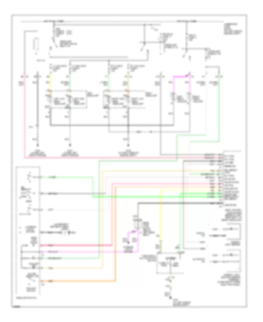
HEADLIGHTS Headlights Wiring Diagram for Isuzu Ascender S 2006 List of elements for Headlights Wiring Diagram for Isuzu Ascender S 2006: 75 (4.2l) (5.3l) (lower right center of dash) sp201 10a 4.2l 5.3l A c2 A12 Ahl/drl defeat ind Ambient light sensor Ambient light/ sunload sensor assembly (in center of upper dash trim panel) Auto Automatic a/c B10 B14 B14 c4 B3 c2 Body control module (bcm) (beneath left rear seat, on rear fuse block) C12 c2 C2 c2 C4 f2 Drl defeat Drl defeat ctrl E11 E14 E6 c1 F10 Flash to pass Fog lp fuse 11 15a Foglamp ind Foglamp relay 39 Foglamp sw Foglamp switch G102 (at left side of engine compt) G103 (at right rear of engine compt) G107 (lower left side of engine) G108 (lower left side of engine) G201 Hdlmp on sig Hdm fuse 53 fuse 57 15a Head Head- lamp on ind Headlamp driver module relay 46 Headlamp hi-relay 43 Headlamp switch High beam Hot at all times Ign coils fuse 14 (5.3l) Ind ctrl Interior lights system Led dim sig Left front foglamp Left headlamp Left high beam headlamp Left low beam headlamp Low beam Low ref Lt high hdlp fuse 5 10a Lt low hdlp fuse 6 10a Manual a/c Nca Park Pnk Rear fuse block (below left rear seat) Right front foglamp Right headlamp Right high beam headlamp Right low beam headlamp Rly ctrl Rt hi hdlp fuse 2 10a Rt low hdlp fuse 3 10a Sense sig Sw on sig Tan Turn signal/ multifunction switch Underhood fuse block (on left side of engine compt)
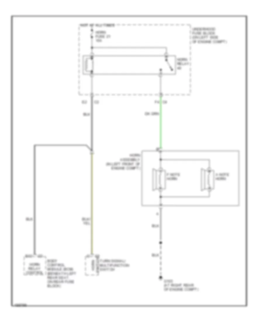
HORN Horn Wiring Diagram for Isuzu Ascender S 2006 List of elements for Horn Wiring Diagram for Isuzu Ascender S 2006: 14 A note horn Body control module (bcm) (beneath left rear seat, on rear fuse block) E12 F note horn F4 c4 G103 (at right rear of engine compt) Horn assembly (in left front of engine compt) Horn fuse 21 15a Horn relay Horn relay control Hot at all times Switch Turn signal/ multifunction switch horn Underhood fuse block (on left side of engine compt)
INSTRUMENT CLUSTER
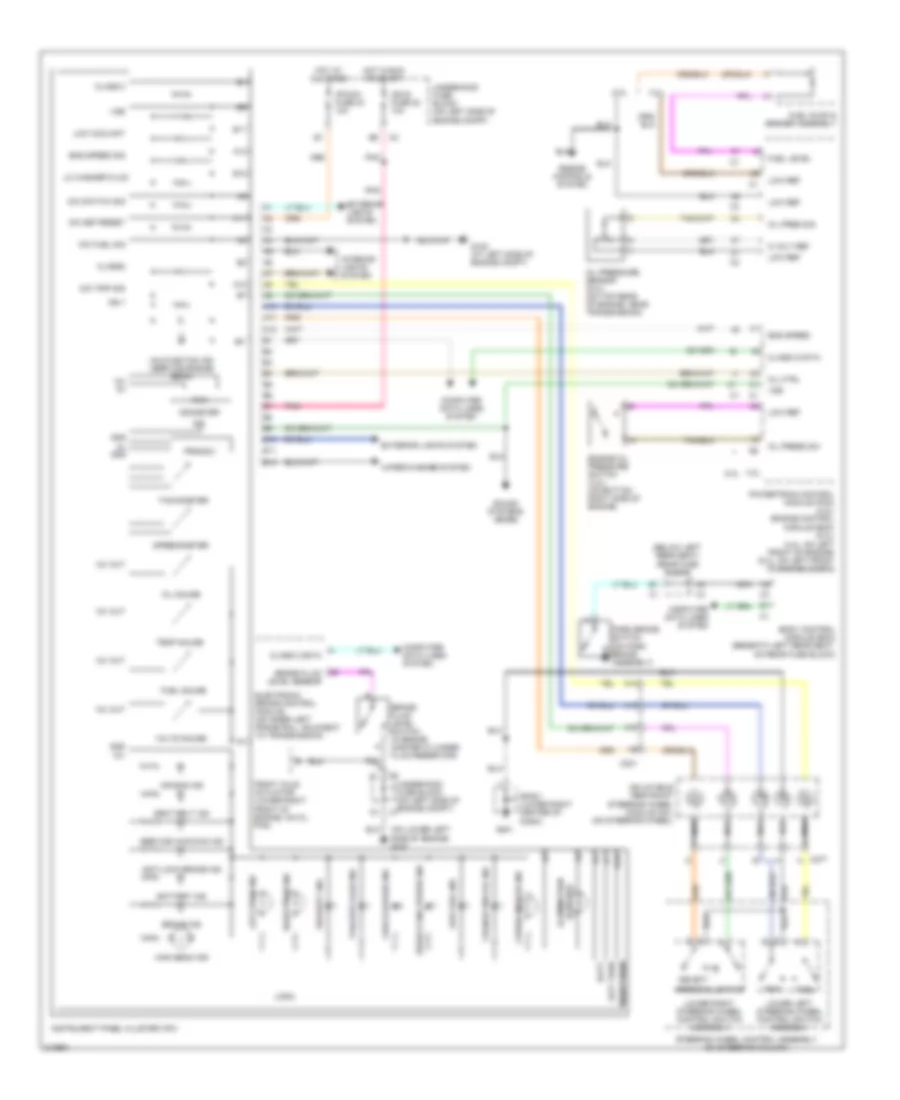
INTERIOR LIGHTS Courtesy Lamps Wiring Diagram (1 of 2) for Isuzu Ascender S 2006 List of elements for Courtesy Lamps Wiring Diagram (1 of 2) for Isuzu Ascender S 2006: 53 (not used) A11 A12 B11 B17 B18 Batt + Body control module (bcm) (beneath left rear seat, on rear fuse block) C1 f12 C2 b10 C3 f6 C4 b3 Courtesy lamp switch Data Door ajar Door ajar input Driver door latch assembly (rear of driver's door) Driver's door module (ddm) (on lower part of driver's door switch panel) F10 F11 F8 c2 Front passenger door latch assembly (rear of right front door) Front passenger's door module(fpdm) (on lower part of passenger's door switch panel) G201 G302 (on lower left "b" pillar) G303 (on lower right "b" pillar) Ground Headlamp switch Hot at all times Interior lamp defeat switch Lamp ctrl Lamp on Lamp supp Left rear door latch assembly (in left rear door) Lift gate ajar input Lift glass ajar input Liftgate latch assembly Liftgate module (inside liftgate) Liftglass ajar switch (inside top of liftgate) Lmp defeat Low ref Lr dr sig Nca Rear fuse block (below left rear seat) Right rear door latch assembly (in right rear door) Rr dr sig Serial data class 2 Sp201 (lower right center of dash) Sp205 (below left side of i/p) Sp306 (under right rear seat) Tan Tbc 3 fuse 4 10a Tbc 4 fuse 40 10a Courtesy Lamps Wiring Diagram (2 of 2) for Isuzu Ascender S 2006 List of elements for Courtesy Lamps Wiring Diagram (2 of 2) for Isuzu Ascender S 2006: 12 Cargo lamp (lwb) Cargo lamp (swb) Center courtesy/ reading lamp Courtesy Front courtesy/ reading lamp G302 (on lower left "b" pillar) Left rear reading lamp (lwb) Left vanity mirror lamp Nca Reading Right rear reading lamp (lwb) Right vanity mirror lamp Instrument Illumination Wiring Diagram (1 of 2) for Isuzu Ascender S 2006 List of elements for Instrument Illumination Wiring Diagram (1 of 2) for Isuzu Ascender S 2006: 42 (automatic a/c) (automatic a/c) (manual a/c) (manual a/c) A15 Auxiliary hvac control module (at rear of lower console) B c1 B1 a1 B1 b16 B9 c1 C1 c C3 e3 C4 b13 Front auxiliary blower motor switch G201 G302 (on lower left "b" pillar) G303 (on lower right "b" pillar) Garage door opener Headlamp switch Hot at all times Hvac control module Inflatable restraint steering wheel module coil Instrument panel cluster (ipc) Left quarter glass switch (lwb) Left rear window switch Lower left switch Lower right switch Lwb Nca Rear fuse block (below left rear seat) Rear window wiper/ washer switch Right quarter glass switch (lwb) Right rear window switch Sp201 (lower right center of dash) Steering wheel control assembly (on steering column) Steering wheel controls fuse Sunroof switch Swb Tbc 2 fuse 7 10a Tbc 5 fuse 32 10a Transfer case shift control switch (4wd) Upper left switch Upper right switch Instrument Illumination Wiring Diagram (2 of 2) for Isuzu Ascender S 2006 List of elements for Instrument Illumination Wiring Diagram (2 of 2) for Isuzu Ascender S 2006: 53 2wd 4 hi 4 lo 5v ref Afwd Ahl/drl defeat indicator Auto B1 pulse width modulated B10 B11 B13 B14 Batt + Body control module (bcm) (beneath left rear seat, on rear fuse block) C4 b11 D1 c2 Data Dimming Driver memory seat switch Driver's door module(ddm) (on lower part of driver's door switch panel) Drl defeat Drl ind E11 E14 F8 c2 Fog rly ctrl G102 (at left side of engine compt) G201 G302 (on lower left "b" pillar) Ground Hdlp on Head Headlamp on indicator Headlamp switch Illum Input Lamp control Lamp indicator front fog Led dim Low ref Mem pwr Nca Park Park lamp on Pnk Rear fuse block (below left rear seat) Sp201 (lower right center of dash) Sp205 (below left side of i/p) Sp306 (under right rear seat) Tan Transfer case shift control module (behind left lower dash) Transfer case shift control switch Underhood fuse block (on left side of engine compt)
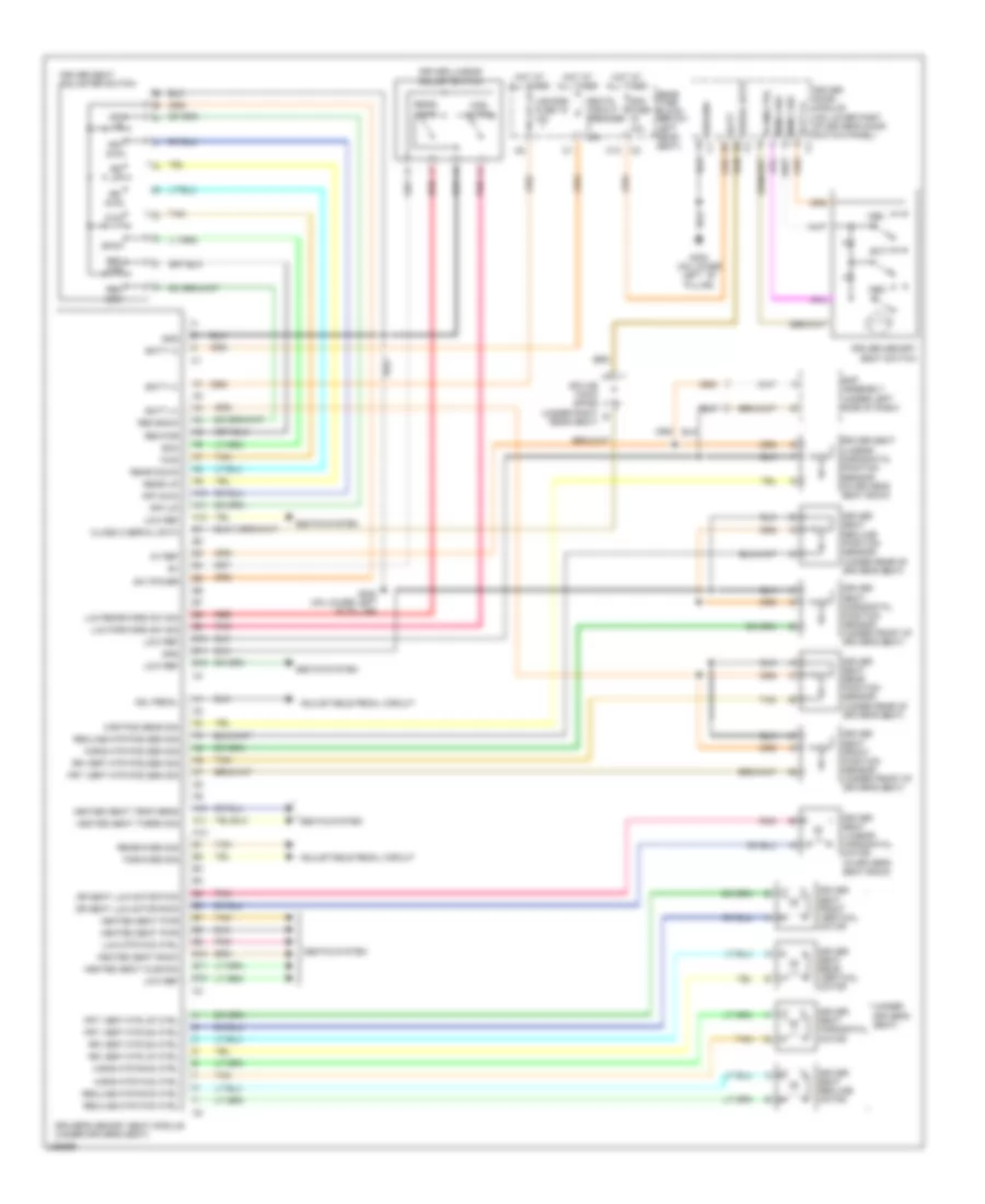
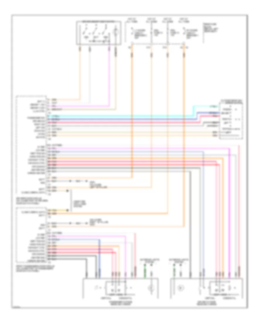
MEMORY SYSTEMS Adjustable Pedal Wiring Diagram for Isuzu Ascender S 2006 List of elements for Adjustable Pedal Wiring Diagram for Isuzu Ascender S 2006: 48 5v ref Adj pedal Aft B10 Back up fuse 27 15a Bat (+) Batt Batt (+) C2 a5 C2 a8 C2 e7 Driver door module (on lower part of driver's door switch panel) Driver memory seat switch Driver's memory seat module (under driver's seat) Eap assembly (under left side of dash) Eap fuse 15 (4.2l) 15a fuse 59 (5.3l) 15a Eap relay (in underhood fuse block) Eap relay 49 Electronic adjustable pedals (eap) switch Exit Fore Forward sig Fuse holder G108 (4.2l: on lower left side of engine) (5.3l: lower left side of engine) G201 G302 (on lower left "b" pillar) Ground Hot at all times Hot in on or start Illum ctrl Lgm/dsm fuse 19 10a Low ref Lt doors circuit breaker 2 25a Mem Mem 2 sw Mem1 sw Memory seats circuit Nca Park/neutral position (pnp) switch (on left side of transmission) Pnk Rear fuse block (below left rear seat) Rearward sig Red Serial data Sp201 (lower right center of dash) Splice pack sp306 (under right rear seat) Tan Underhood fuse block (on left side of engine compt) Driver"s Memory Seat Wiring Diagram for Isuzu Ascender S 2006 List of elements for Driver"s Memory Seat Wiring Diagram for Isuzu Ascender S 2006: 94 (under 5v ref A10 A11 A12 Adj pedal Adjustable pedal circuit B10 B11 B12 Bac Back Batt Batt (+) C2 c10 Class 2 serial data Ddm fuse 10a Dr seat lum motor fwd Dr seat lum motor rwd Driver door module (on lower part of driver's door switch panel) Driver lumbar adjust switch Driver memory seat switch Driver seat adjuster switch Driver seat front position sensor (under front of driver's seat) Driver seat front vertical motor Driver seat horizontal motor Driver seat horizontal position sensor (under front of driver's seat) Driver seat lumbar horizontal motor (in driver's seat back) Driver seat lumbar horizontal position sensor (in driver's seat back) Driver seat rear position sensor (under rear of driver's seat) Driver seat rear vertical motor Driver seat recline motor Driver seat recline position sensor (under rear of driver's seat) Driver's seat) Driver's memory seat module (under driver's seat) Eap assembly (under left side of dash) Exit For- ward Forward sig Frt dwn Frt up Frt vert mtr dn ctrl Frt vert mtr pos sen sig Frt vert mtr up ctrl Frt-dwn Frt-up Fwd G302 (on lower left ``b" pillar) Gnd Ground c1 Heated seat back Heated seat cushion Heated seat pwr Heated seat temp sens Heated seat therm sig Hor pos sens sig Horiz mtr fwd ctrl Horiz mtr pos sen sig Horiz mtr rwd ctrl Hot at all times Illum ctrl Lgm/dsm fuse 19 10a Low ref Lum forward sw sig Lum mtr fwd ctrl Lum rearward sw sig Mem Mem 1 sw Mem 2 sw Pnk Rear down Rear fuse block (below left rear seat) Rear up Rear- ward Rearward sig Rec bck Rec for Rec-back Rec-for Recline mtr fwd ctrl Recline mtr pos sen sig Recline mtr rwd ctrl Red Rr dwn Rr up Rr vert mtr dn ctrl Rr vert mtr pos sen sig Rr vert mtr up ctrl Seats circuit breaker 30a Seats system Serial data c2 Splice pack sp306 (under right rear seat) Sw power Tan Memory Mirrors Wiring Diagram for Isuzu Ascender S 2006 List of elements for Memory Mirrors Wiring Diagram for Isuzu Ascender S 2006: 56 (on lower right ``b" pillar) g303 5v ref Bat (+) Batt C10 Class 2 serial data Computer data lines system D10 Ddm fuse 10 10a Door switch panel) Down Down sig Driver Driver memory seat switch Driver outside rearview mirror Driver sig Driver's door module (on lower part of driver's Exit Exterior lights system Front passenger's door module (on lower part of passenger's door switch panel) G302 (on lower left ``b" pillar) Gnd Heater gnd Horiz Horiz pos sig Horizontal Hot at all times Ign pwr Illum ctrl Left Left sig Low ref Lt doors circuit breaker 2 25a Mem Memory 1 sw Memory 2 sw Mir common Mir down ctrl Mir right ctrl Mirror heater Outside rearview mirror switch Pass Passenger outside rearview mirror Passenger sig Pdm fuse 12 10a Pnk Rear fuse block (below left rear seat) Red Right Right sig Rt doors circuit breaker 1 25a Tan Up sig Vert Vert pos sig Vertical
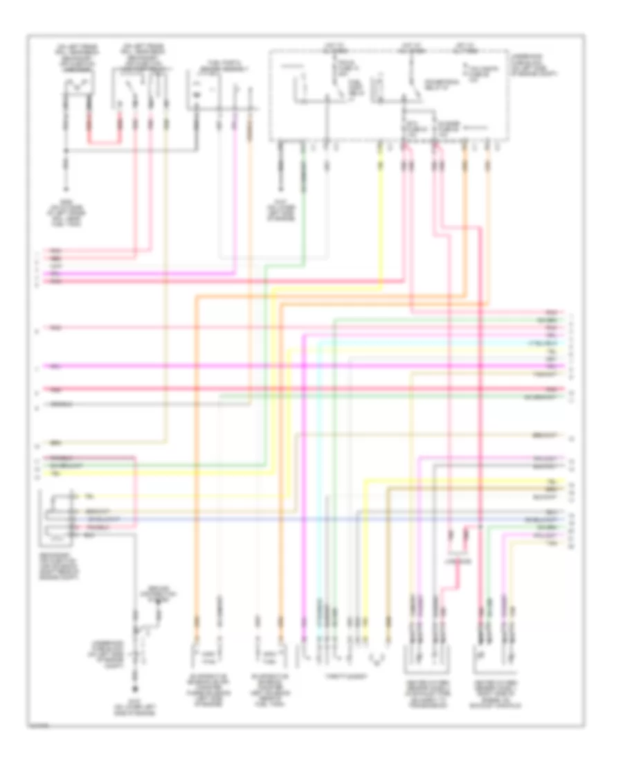
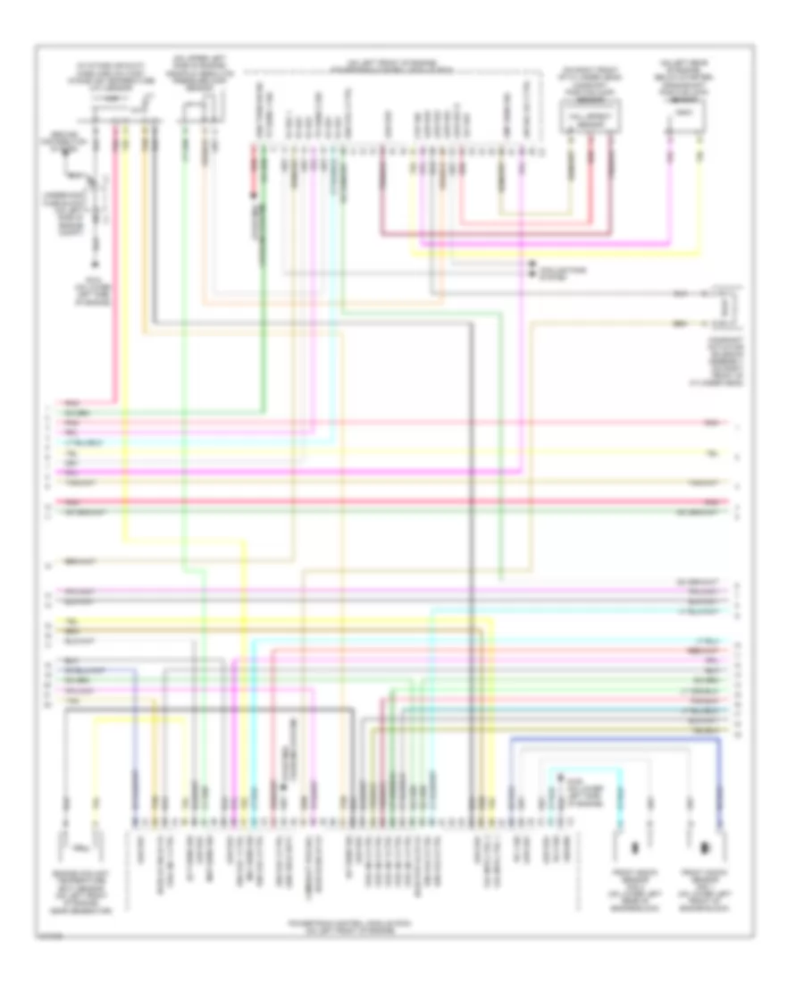
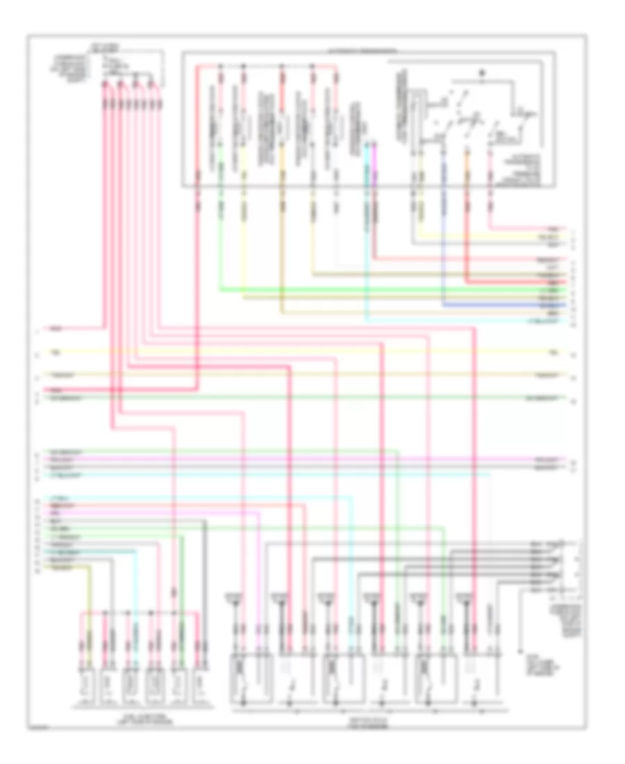
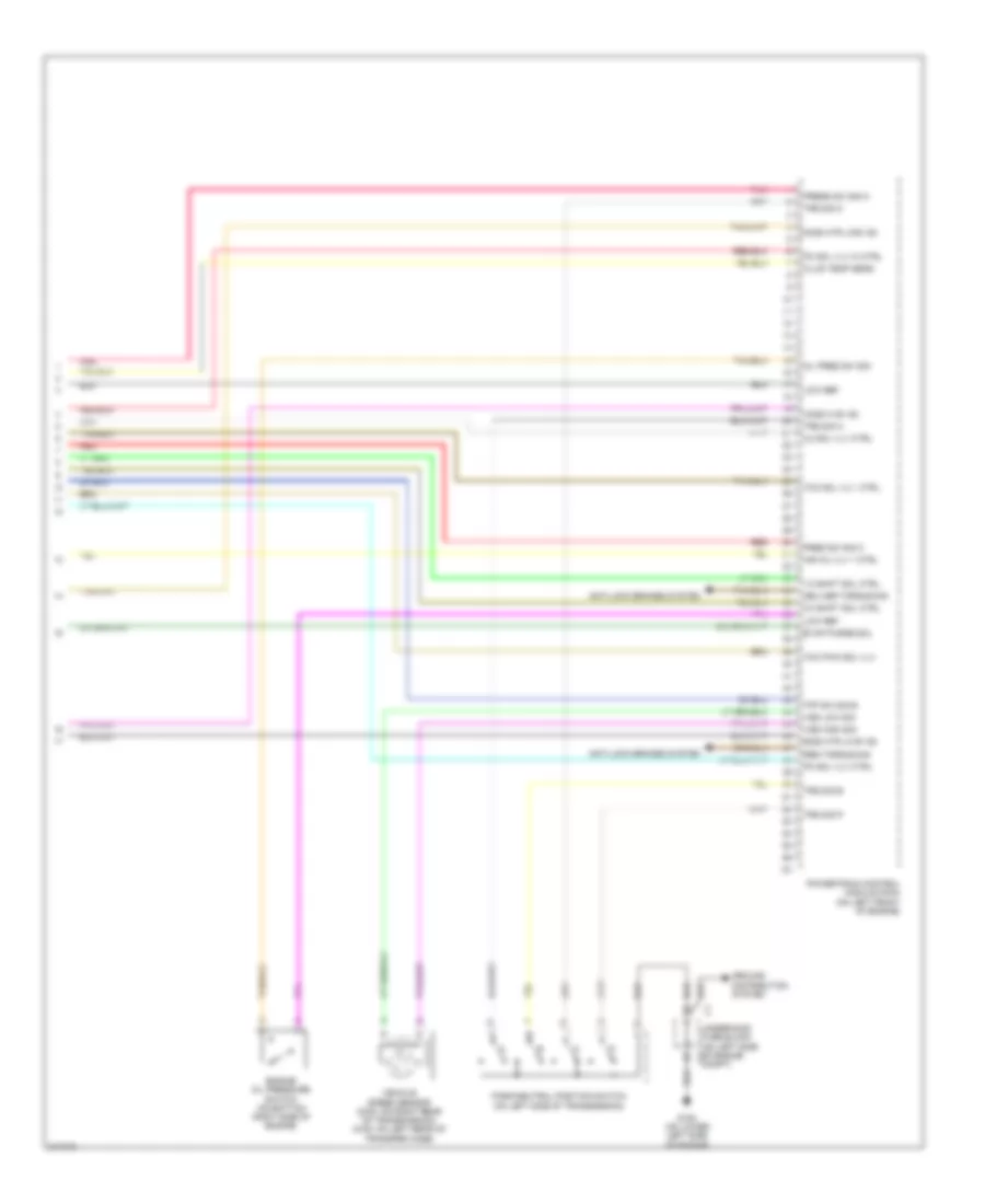
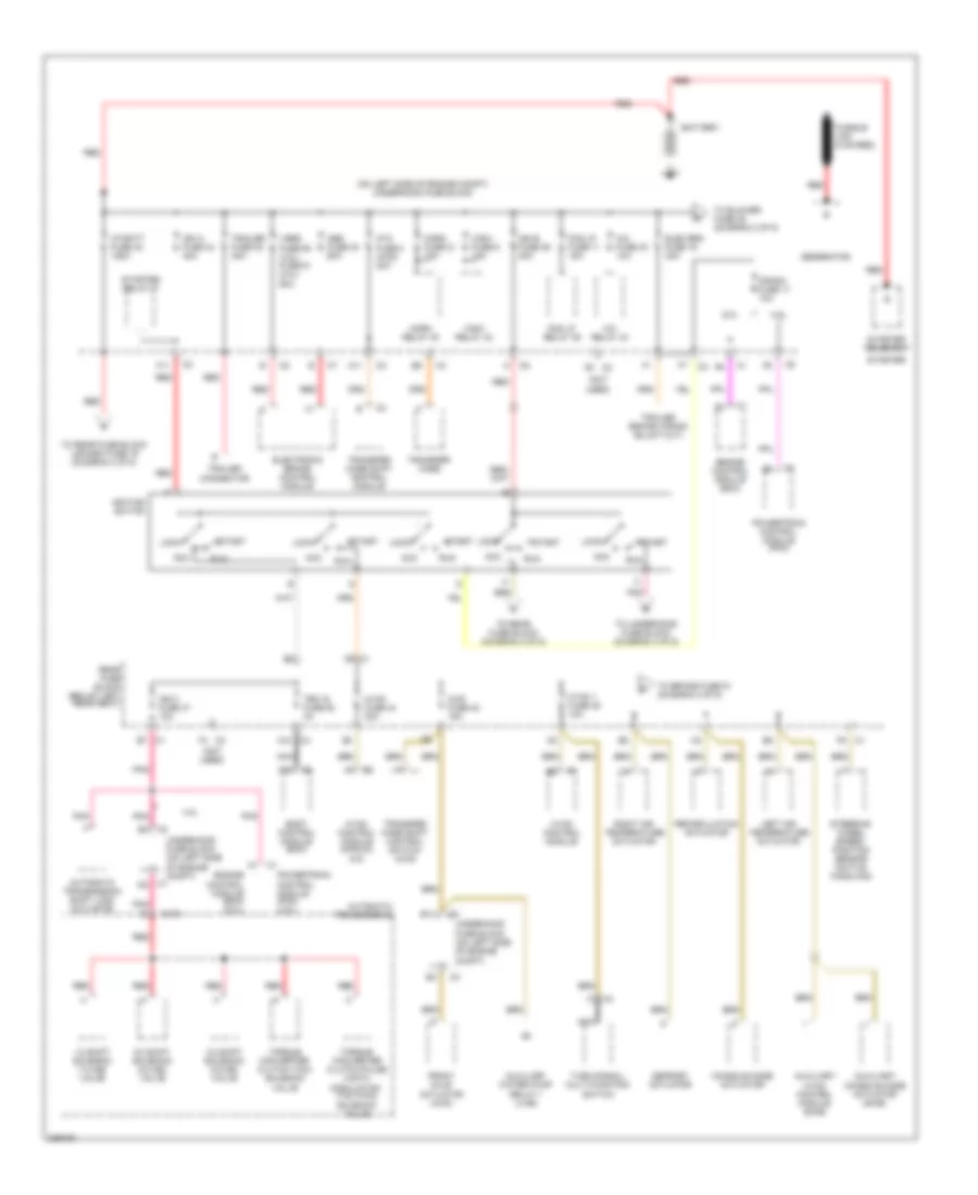
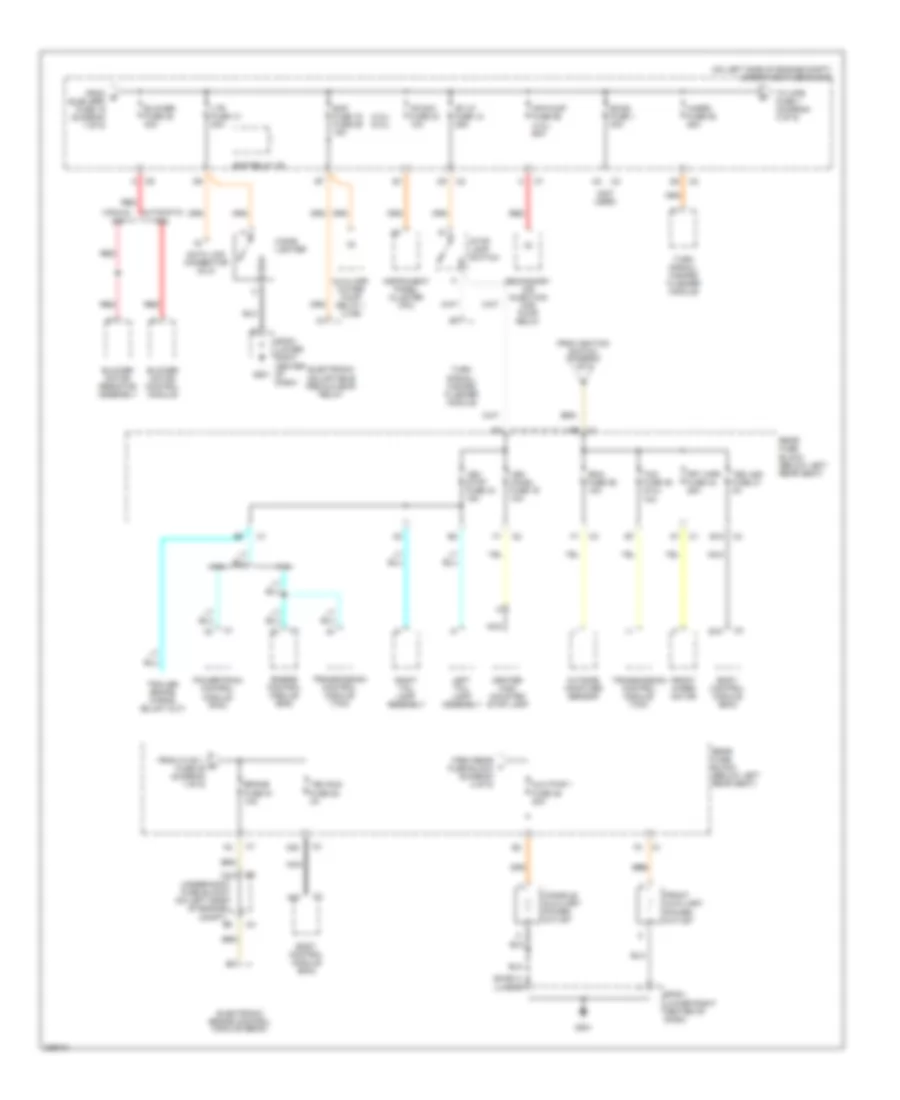
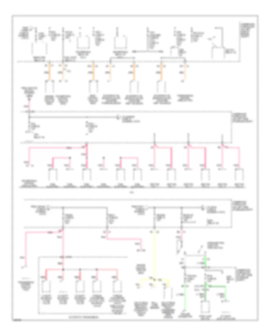
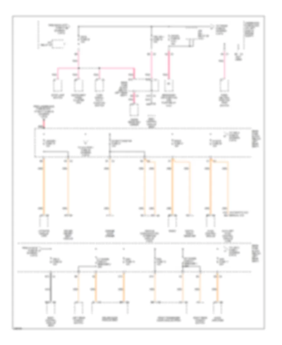
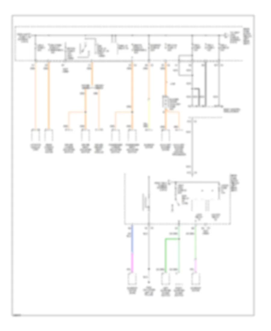
POWER DISTRIBUTION Power Distribution Wiring Diagram (1 of 5) for Isuzu Ascender S 2006 List of elements for Power Distribution Wiring Diagram (1 of 5) for Isuzu Ascender S 2006: 85 (not used) (on left side of engine compt) underhood fuse block 1-2 shift solenoid (1-2 ss) valve 2-3 shift solenoid (2-3 ss) valve 3-2 shift solenoid (3-2 ss) valve 4.2l 4wd fuse 48 15a 5.3l A/c fuse 30 10a A/c relay 44 A11 A18 Abs fuse 33 60a Acc Atc fuse 8 (4wd) 30a Automatic transmission Automatic transmission shift lock actuator Auxiliary console mode actuator (swb) Auxiliary hvac control module (swb) Auxiliary water pump relay 1 (lwb) B11 Battery Body control module (bcm) C175 C2 f6 Console mode actuator Crank fuse 17 10a D9 c1 Defrost actuator Elec brk fuse 19 30a Electronic brake control module Engine control module (ecm) Engine control module (ecm) (5.3l) F11 Fog lp fuse 11 15a Fog lp relay 39 Front axle actuator (4wd) Fusible link (8 ga-red) Generator Horn fuse 21 15a Horn relay 40 Hvac 1 fuse 39 10a Hvac control module Hvac control module (manual a/c) Hvac fuse 44 30a I/p batt fuse 48 125a Ign 0 fuse 47 10a Ign a fuse 34 40a Ign b fuse 36 40a Ignition switch Left air temperature actuator Lock Nca Pnk Powertrain control module (pcm) Powertrain control module (pcm) (4.2l) Rear fuse block (below left rear seat) Recirculation actuator Red Right air temperature actuator Run Start Starter Starter relay 47 Starter solenoid Steering wheel speed/ position sensor (active handling) Tbc ig fuse 50 3a To blower fuse 35 (diagram 2 of 5) To brake fuse 51 (diagram 2 of 5) To rear fuse block (diagram 2 of 5) To rear fuse block lgm/dsm fuse 19 (diagram 4 of 5) To underhood fuse block (diagram 3 of 5) Torque converter clutch (tcc) solenoid valve Torque converter clutch pulse width modulation (tcc pwm) solenoid valve Trailer connector Trailer fuse 32 30a Transfer case Transfer case shift control module Transfer case shift control switch (4wd) Turn signal/ multi-function switch Underhood fuse block (on left side of engine compt) Underhood fuse block (on left side of engine compt) c1 Vses fuse 58 (4.2l) fuse 61 (5.3l) 60a Wsw fuse 9 15a Wsw relay 42 Power Distribution Wiring Diagram (2 of 5) for Isuzu Ascender S 2006 List of elements for Power Distribution Wiring Diagram (2 of 5) for Isuzu Ascender S 2006: 63 (4.2l) (5.3l) (lwb) (not used) (on left side of engine compt) underhood fuse block (swb) m e 4.2l 5.3l A20 Air pump fuse 56 (4.2l) 60a Automatic a/c Aux pwr 1 fuse 46 20a Auxiliary water pump relay 1 (lwb) B15 Blower fuse 35 40a Blower motor control module Blower motor resistor assembly Body control module (bcm) Brake fuse 51 10a C11 Center high mounted stop lamp Cigar lighter Console auxiliary power outlet Data link connector (dlc) Eap fuse 15 fuse 59 15a Eap relay 49 Ecas fuse 1 30a Electronic adjustable pedals (eap) relay Electronic brake control module (ebcm) Engine control module (ecm) From b elec brk fuse 19 (diagram 1 of 5) From hvac 1 c fuse 39 (diagram 1 of 5) From ignition switch (diagram 1 of 5) From rear l fuse block (diagram 4 of 5) Front auxiliary power outlet Front wiper motor Frt wpr fuse 33 25a G201 Hazrd fuse 52 25a Instrument panel cluster (ipc) Ipc/dic fuse 24 10a Left tail lamp assembly Ltr fuse 13 20a Manual a/c Nca Outside moisture sensor Powertrain control module (pcm) Rain fuse 29 10a Rear fuse block (below left rear seat) Red Right tail lamp assembly Secondary air injection (air) pump relay Sp201 (lower right center of dash) St/lp fuse 12 25a Stop lamp switch Tbc acc fuse 31 3a Tbc run fuse 52 3a Tcm fuse 35 (5.3l) 10a To wpr fuse 7 (diagram 3 of 5) Transmission control module (tcm) Turn signal/ hazard flasher module Underhood fuse block (on left side of engine compt) Veh chmsl fuse 16 10a Veh stop fuse 34 15a Power Distribution Wiring Diagram (3 of 5) for Isuzu Ascender S 2006 List of elements for Power Distribution Wiring Diagram (3 of 5) for Isuzu Ascender S 2006: 75 (4.2l) (5.3l) (diagram 4 of 5) 1-2 shift solenoid (1-2 ss) valve 2-3 shift solenoid (2-3 ss) valve 3-2 shift solenoid (3-2 ss) valve 4.2l 5.3l A/t shift lock actuator A5 c3 Air bag fuse 18 10a Automatic transmission B11 c1 Back-up fuse 27 15a Body control module (bcm) Btsi fuse 25 10a C175 C2 f8 E10 E12 Eap relay Eap relay 49 Ecm 1 fuse 28 (5.3l) 15a Ecm fuse 29 (5.3l) 10a Engine control module (ecm) Evaporative emission (evap) canister purge solenoid Evaporative emission (evap) canister vent solenoid Fan fuse 20 10a Fan relay 45 From air sol fuse 54 m From d hazrd fuse 52 (diagram 2 of 5) From ignition switch (diagram 1 of 5) From pcm 1 fuse 28 f (diagram 3 of 5) Fuel injector 1 Fuel injector 2 Fuel injector 3 Fuel injector 4 Fuel injector 5 Fuel injector 6 Fuel pump relay 41 Hdlp-hi relay 43 Hdm fuse 53 (4.2l) fuse 57 (5.3l) 15a Hdm relay Ign coils fuse 14 (5.3l) 10a Ignition coil 1 Ignition coil 2 Ignition coil 3 Ignition coil 4 Ignition coil 5 Ignition coil 6 Inflatable restraint front passenger presence (pps) module Inflatable restraint sensing & diagnostic module (sdm) Park/neutral position (pnp) switch Pcm 1 fuse 28 (4.2l) 15a Pcm b fuse 10 20a Pnk Powertrain control module (pcm) Powertrain relay 57 (4.2l) Powertrain relay 60 (5.3l) Rear wpr relay 38 Red Roll- over sensor Stop lamp switch Tbc 1 fuse 31 (4.2l) fuse 58 (5.3l) 10a Tcm/ canister fuse 26 (4.2l) fuse 15 (5.3l) 10a To air bag fuse 18 (diagram 3 of 5) To ign e fuse 22 (diagram 4 of 5) Torque converter clutch (tcc) solenoid valve Torque converter clutch pulse width modulation (tcc pwm) solenoid valve Trailer connector Trans fuse 53 (5.3l) 15a Transmission control module (tcm) Trlr b/u fuse 4 10a Underhood fuse block (on left side of engine compt) Wpr fuse 7 20a Power Distribution Wiring Diagram (4 of 5) for Isuzu Ascender S 2006 List of elements for Power Distribution Wiring Diagram (4 of 5) for Isuzu Ascender S 2006: 56 (not used) A/c relay 44 A16 (automatic a/c) (manual a/c) A19 Air sol fuse 54 (4.2l) 15a Air sol relay 55 (4.2l) Amp fuse 11 20a Audio amplifier Auxiliary hvac control module (lwb) B13 Body control module (bcm) C10 D10 D12 Ddm fuse 10 10a Digital radio receiver Driver door module (ddm) Driver memory seat module E12 E2 c3 From back-up fuse 27 g (diagram 3 of 5) From hvac b fuse 36 h (diagram 4 of 5) From underhood fuse block, i/p batt fuse 48 (diagram 1 of 5) Front passenger door module (fpdm) Garage door opener Hvac b fuse 36 10a Hvac control module Ign e fuse 22 10a Inside rearview mirror Instrument panel cluster (ipc) Left rear window switch Lgm/dsm fuse 19 10a Liftgate module (lgm) Lt doors circuit breaker 2 25a Nca Oh batt/onstar fuse 27 10a Park/ neutral position (pnp) switch Pdm fuse 12 10a Pnk Radio Radio fuse 41 15a Rear fuse block (below left rear seat) Red Right rear window switch Rt doors circuit breaker 1 25a Secondary air injection (air) pump relay (4.2l) Stop lamp switch Tbc 5 fuse 32 10a Tbc ign 1 fuse 16 10a To aux pwr 1 fuse 46 (diagram 2 of 5) To lgm 2 fuse 3 (diagram 5 of 5) To tbc 5 fuse 32 (diagram 4 of 5) To trans fuse 53 (diagram 3 of 5) Turn signal/ multi- function switch Underhood fuse block (on left side of engine compt) Vehicle communication interface module (vcim) Power Distribution Wiring Diagram (5 of 5) for Isuzu Ascender S 2006 List of elements for Power Distribution Wiring Diagram (5 of 5) for Isuzu Ascender S 2006: 44 (not used) A12 Auxiliary blower motor Auxiliary blower motor control processor B17 B17 c3 Blower motor auxiliary fuse 30a Body control module (bcm) Driver lumbar adjuster switch Driver memory seat module Driver seat adjuster switch From amp fuse 11 j (diagram 4 of 5) From tbc 4 k fuse 40 (diagram 5 of 5) G302 (on lower left "b" pillar) Left quarter glass switch Lgm 2 fuse 3 30a Liftgate module (lgm) Lock relay Locks fuse 10a Lwb Memory seats Nca Park lp relay 30 Passenger lumbar adjuster switch Passenger seat adjuster switch Power seats Rap relay (lwb) Rear fuse block (below left rear seat) Rear window wiper motor Right quarter glass switch Rr fog fuse 5 10a (not used) Rr fog lp relay 45 (not used) Rr hvac fuse 13 30a Rr wiper circuit breaker 9 15a Seats circuit breaker 8 30a Sunroof fuse 28 20a Sunroof motor Sunroof motor (swb) Tbc 2 fuse 7 10a Tbc 3 fuse 4 10a Tbc 4 fuse 40 10a To vent wdo fuse 20 (diagram 5 of 5) Unlock relay Vent wdo fuse 20 20a
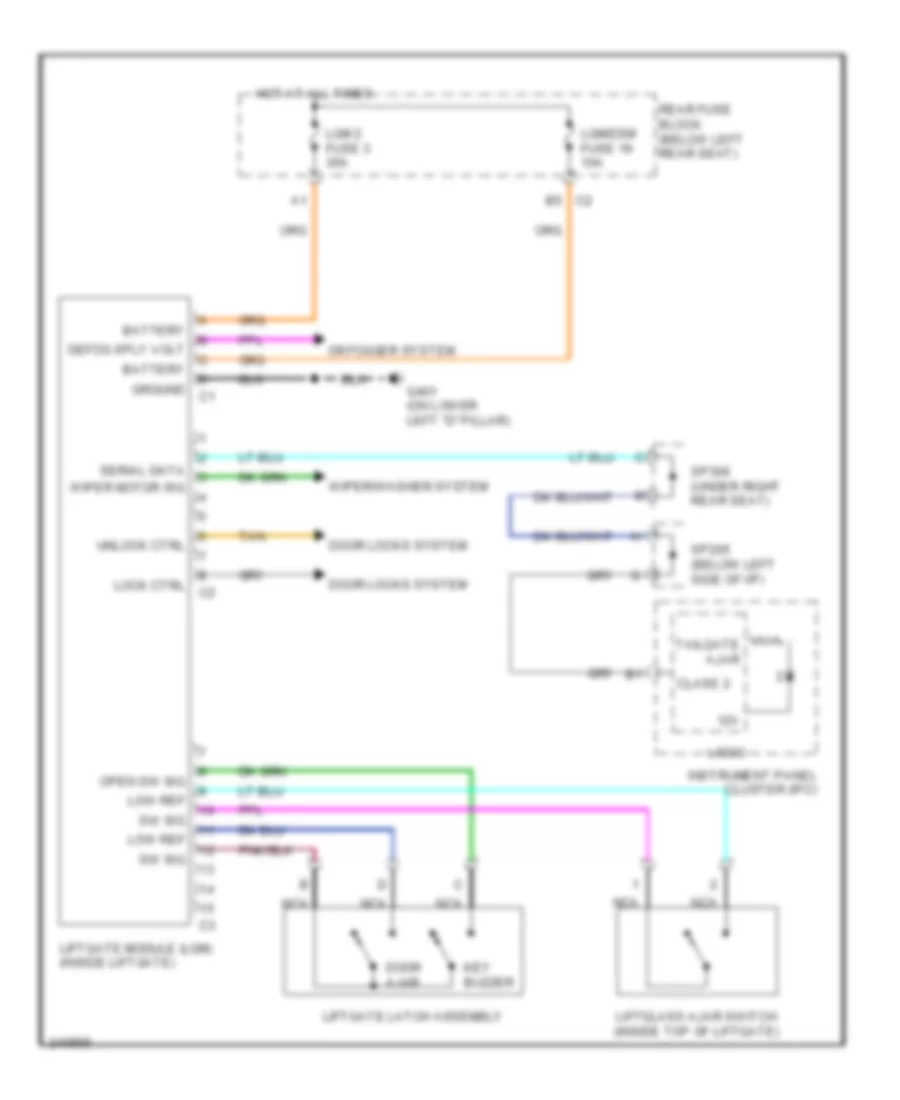
POWER DOOR LOCKS Power Door Locks Wiring Diagram (1 of 2) for Isuzu Ascender S 2006 List of elements for Power Door Locks Wiring Diagram (1 of 2) for Isuzu Ascender S 2006: 47 (on lower left "b" pillar) g302 A12 A13 B c2 B10 Batt Body control module (bcm) (beneath left rear seat, on rear fuse block) C c1 C10 C4 a13 C4 a5 D10 Ddm fuse 10a Door ajar Door ajar switch Driver door lock switch Driver's door module (on lower part of driver's door switch panel) F10 Front passenger door module (on lower part of passenger's door switch panel) Front passenger's door latch assembly (rear of right front door) G302 (on lower left "b" pillar) G303 (on lower right "b" pillar) Ground Hot at all times Lock Lock ctrl Lock relay Lock relay 18 Locks fuse 21 10a Low ref Lr door ajar Lt doors circuit breaker 25a Nca Passenger door lock switch Pdm fuse 10a Power Rear fuse block (below left rear seat) Right rear door latch assembly (in right rear door) Rr door ajar Rt doors circuit breaker 25a Serial data Sp205 (below left side of i/p) Tan Unlock Unlock ctrl Unlock relay Unlock relay 24 Power Door Locks Wiring Diagram (2 of 2) for Isuzu Ascender S 2006 List of elements for Power Door Locks Wiring Diagram (2 of 2) for Isuzu Ascender S 2006: 24 (rear of driver's door) driver's door latch assembly Ajar sw low Ajar sw sig B c2 Battery C2 b5 Door ajar Door ajar switch G302 (on lower left "b" pillar) Hot at all times Key buzzer Left rear door latch assembly (in left rear door) Lgm/dsm fuse 6 10a Liftgate ajar Liftgate latch assembly Liftgate module (inside liftgate) Liftgate open Liftglass ajar switch (inside top of liftgate) Lock ctrl Rear fuse block (below left rear seat) Serial data Sp306 (under right rear seat) Tan Unlock ctrl
POWER MIRRORS Automatic Day/Night Mirror Wiring Diagram for Isuzu Ascender S 2006 List of elements for Automatic Day/Night Mirror Wiring Diagram for Isuzu Ascender S 2006: 25 (above left side of grille) (manual a/c) ambient air temperature sensor Air temp sensor B12 B6 c2 Back up lamp voltage output Back up voltage Body control module (bcm) (beneath left rear seat, on rear fuse block) Computer data lines system E10 E12 G302 (on lower left ``b" pillar) Ground Hot in on or start Ign 1 Ign e fuse 22 10a Inside rearview mirror Low ref Manual a/c Nca On/off Photo sensor Pnk Rear fuse block (below left rear seat) Serial data Underhood fuse block (on left side of engine compartment) Power Mirrors Wiring Diagram for Isuzu Ascender S 2006 List of elements for Power Mirrors Wiring Diagram for Isuzu Ascender S 2006: 45 5v ref Battery C10 Class 2 serial data Computer data lines system D10 Ddm fuse 10 10a Defogger Defogger system Down Down sig Driver Driver outside rearview mirror Driver sig Driver's door module (on lower part of driver's door switch panel) Front passenger's door module (on lower part of passenger's door switch panel) G302 (on lower left "b" pillar) G303 (on lower right "b" pillar) Ground Horiz pos sig Horizontal Hot at all times Ign voltage Left Left sig Low ref Lt doors circuit breaker 2 25a Mir common Mir down ctrl Mir right ctrl Outside rearview mirror switch Pass Passenger outside rearview mirror Passenger sig Pdm fuse 12 10a Pnk Rear fuse block (below left rear seat) Red Right Right sig Rt doors circuit breaker 1 25a Tan Up sig Vert pos sig Vertical
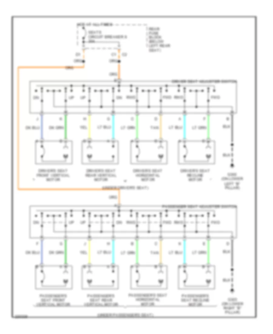
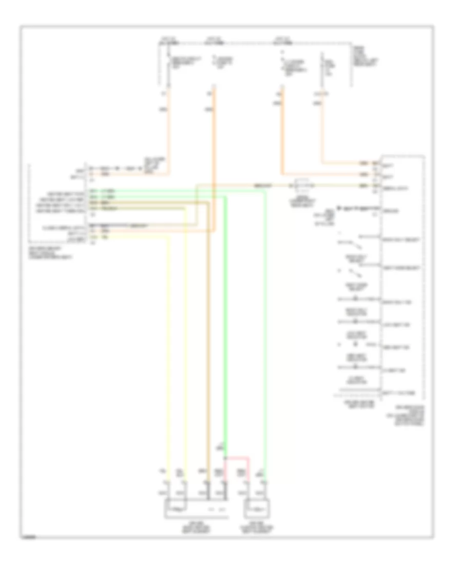
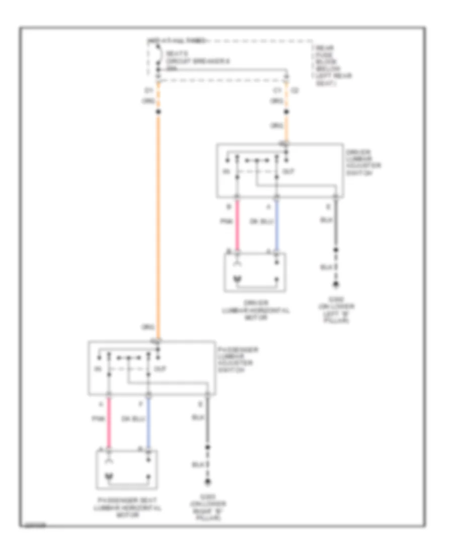
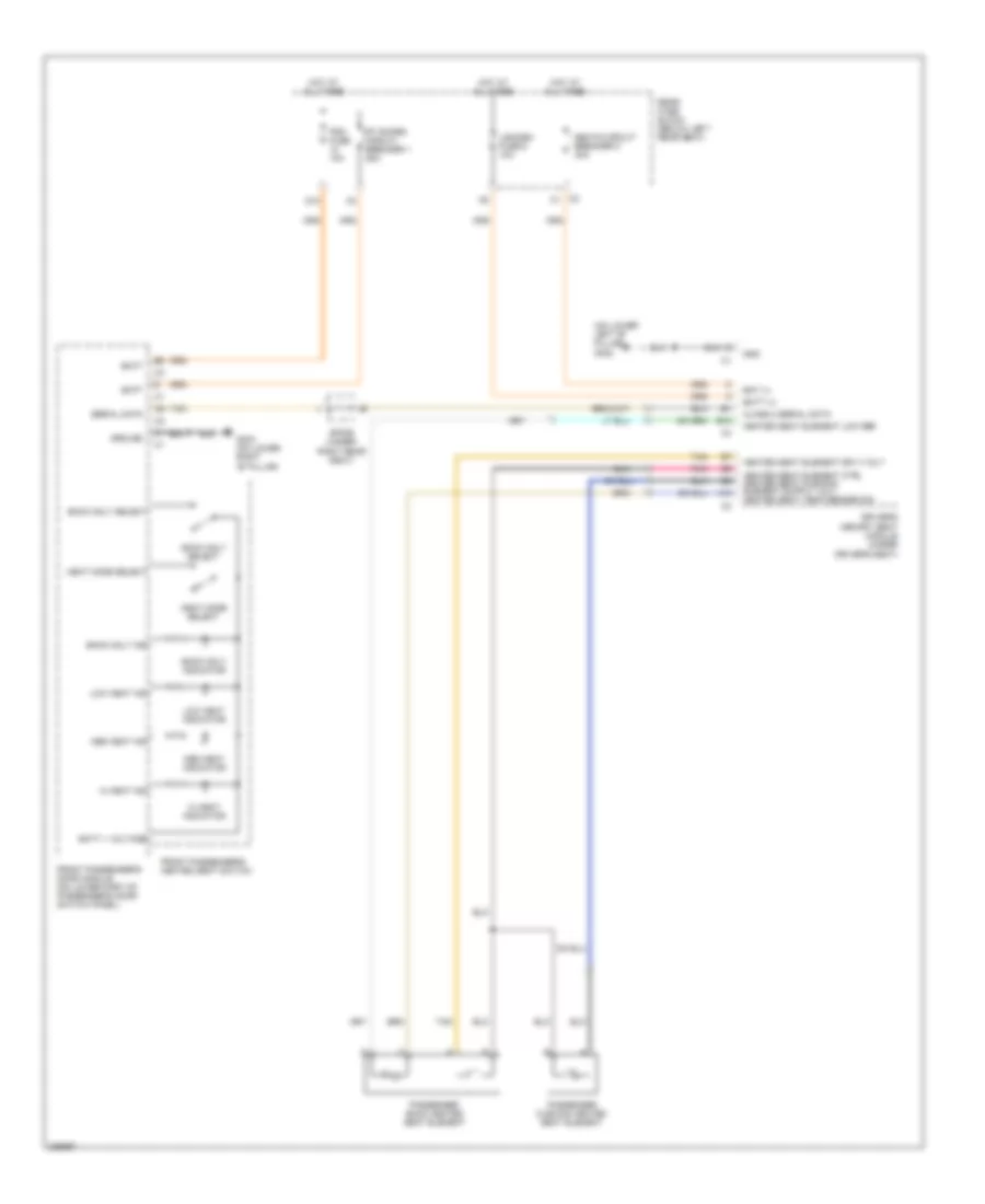
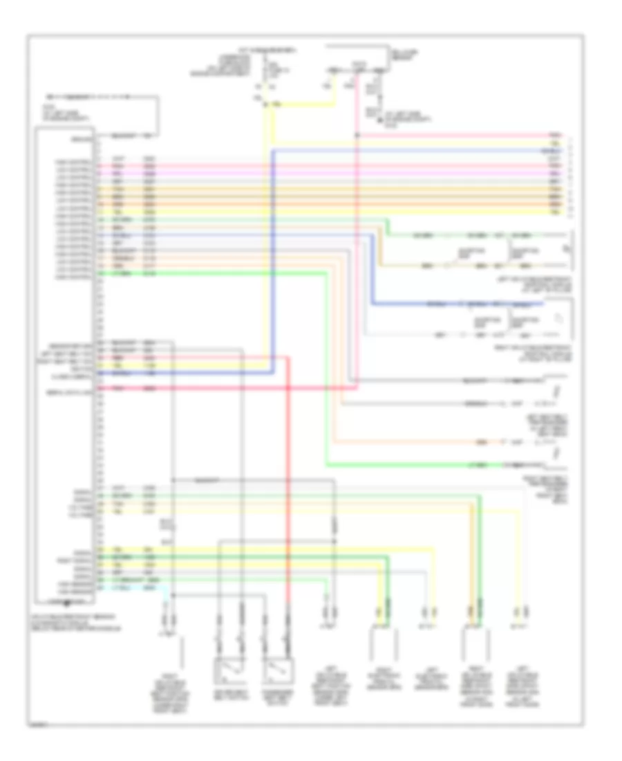
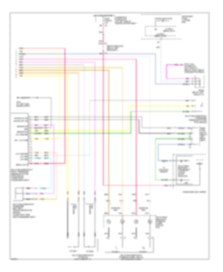
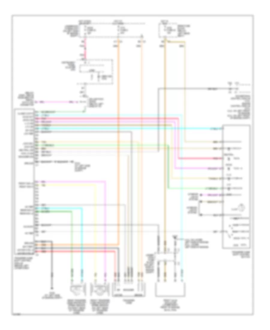
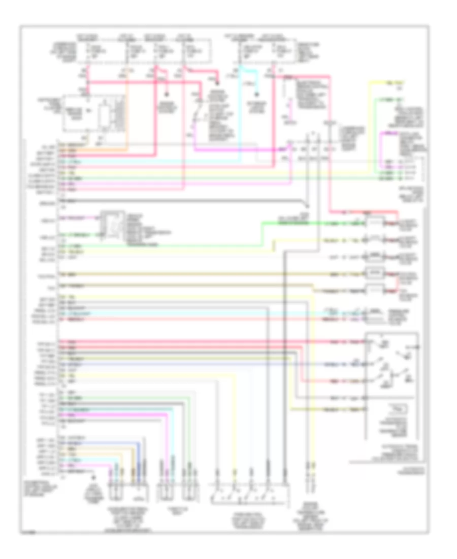
POWER SEATS 8-Way Adjustable Power Seat Wiring Diagram for Isuzu Ascender S 2006 List of elements for 8-Way Adjustable Power Seat Wiring Diagram for Isuzu Ascender S 2006: 21 (under driver's seat) (under passenger's seat) Driver seat adjuster switch Driver's seat front vertical motor Driver's seat horizontal motor Driver's seat rear vertical motor Driver's seat recline motor Fwd G302 (on lower G303 (on lower right "b" pillar) Hot at all times Left "b" pillar) Passenger seat adjuster switch Passenger's seat front vertical motor Passenger's seat horizontal motor Passenger's seat rear vertical motor Passenger's seat recline motor Rear fuse block (below left rear seat) Rwd Seats circuit breaker 8 30a Tan Driver"s Heated Seat Wiring Diagram for Isuzu Ascender S 2006 List of elements for Driver"s Heated Seat Wiring Diagram for Isuzu Ascender S 2006: 44 (on lower left "b" pillar) g302 A11 A12 B10 B11 B12 Back only ind Back only indicator Back only select Bat (+) Batt Batt (+) Batt + voltage C2 c10 Class 2 serial data Ddm fuse 10a Driver back heated seat element Driver cushion heated seat element Driver heated seat switch Driver's door module (on lower part of driver's door switch panel) Driver's memory seat module (under driver's seat) G302 (on lower left "b" pillar) Gnd Ground Heat mode select Heated seat low ref Heated seat pwr Heated seat sply volt Heated seat therm sig Hi heat ind Hi heat indicator Hot at all times Lgm/dsm fuse 19 10a Low heat ind Low heat indicator Low ref Lt doors circuit breaker 2 25a Med heat ind Med heat indicator Nca Rear fuse block (below left rear seat) Seats circuit breaker 8 30a Serial data Sp306 (under right rear seat) Lumbar Wiring Diagram for Isuzu Ascender S 2006 List of elements for Lumbar Wiring Diagram for Isuzu Ascender S 2006: 13 Driver lumbar adjuster switch Driver lumbar horizontal motor G302 (on lower G303 (on lower Hot at all times Left "b" pillar) Out Passenger lumbar adjuster switch Passenger seat lumbar horizontal motor Pnk Rear fuse block (below left rear seat) Right "b" pillar) Seats circuit breaker 8 30a Passenger"s Heated Seat Wiring Diagram for Isuzu Ascender S 2006 List of elements for Passenger"s Heated Seat Wiring Diagram for Isuzu Ascender S 2006: 40 (on lower left "b" pillar) g302 A10 B12 Back only ind Back only indicator Back only select Bat (+) Batt Batt (+) Batt + voltage C2 c1 Class 2 serial data D10 Driver's memory seat module (under driver's seat) Front passenger's door module (on lower part of passenger's door switch panel) Front passenger's heated seat switch G303 (on lower right "b" pillar) Gnd Ground Heat mode select Heated seat element low ref Heated seat element sply volt Hi heat ind Hi heat indicator Hot at all times Lgm/dsm fuse 6 10a Low heat ind Low heat indicator Med heat ind Med heat indicator Passenger back heated seat element Passenger cushion heated seat element Pdm fuse 10a Pnk Rear fuse block (below left rear seat) Rt doors circuit breaker 1 25a Seats circuit breaker 8 30a Serial data Sp306 (under right rear seat) Tan
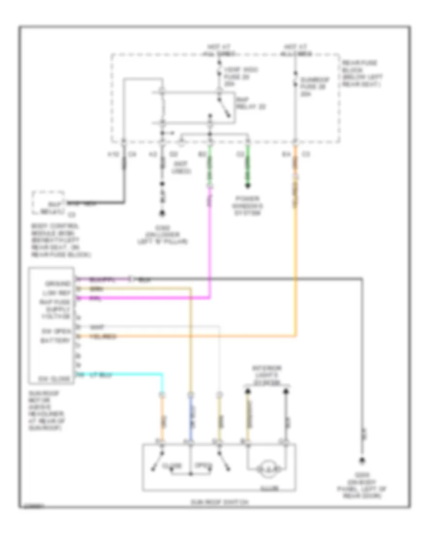
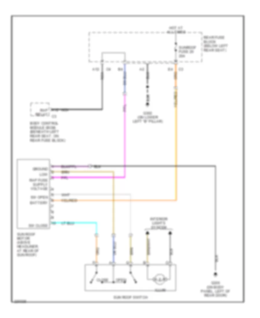
POWER TOP/SUNROOF Power Top/Sunroof Wiring Diagram, Long Wheel Base for Isuzu Ascender S 2006 List of elements for Power Top/Sunroof Wiring Diagram, Long Wheel Base for Isuzu Ascender S 2006: 24 (not used) A12 nca A12 rap relay c3 Battery Body control module (bcm) (beneath left rear seat, on rear fuse block) Close G302 (on lower left "b" pillar) G306 (on body panel, left of rear door) Ground Hot at all times Illum Interior lights system Low ref Nca Open Power windows system Rap relay 22 Rear fuse block (below left rear seat) Sun roof motor (above headliner, at rear of sun roof) Sun roof switch Sunroof fuse 28 20a Sw close Sw open Vent wdo fuse 20 20a Power Top/Sunroof Wiring Diagram, Short Wheel Base for Isuzu Ascender S 2006 List of elements for Power Top/Sunroof Wiring Diagram, Short Wheel Base for Isuzu Ascender S 2006: 20 A12 nca A12 rap relay c3 Battery Body control module (bcm) (beneath left rear seat, on rear fuse block) Close G302 (on lower left "b" pillar) G306 (on body panel, left of rear door) Ground Hot at all times Illum Interior lights system Low Nca Open Rear fuse block (below left rear seat) Sun roof motor (above headliner, at rear of sun roof) Sun roof switch Sunroof fuse 20 20a Sw close Sw open
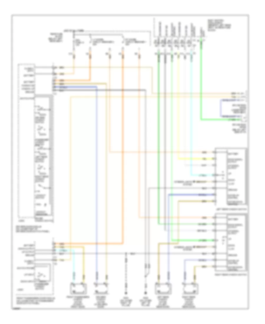
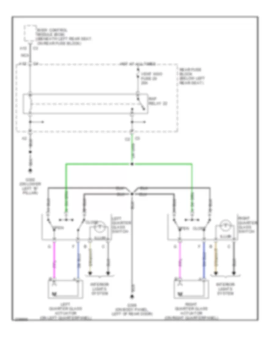
POWER WINDOWS Power Windows Wiring Diagram for Isuzu Ascender S 2006 List of elements for Power Windows Wiring Diagram for Isuzu Ascender S 2006: 57 (on lower left ``b" pillar) (on lower right ``b" pillar) A6 nca B5 nca B6 nca B7 nca B8 nca B9 nca Battery Body control module (bcm) (beneath left rear seat, on rear fuse block) Class 2 data Ddm fuse 10 10a Down Down input Down output Down signal output Driver window switch Driver's door module (on lower part of driver's door switch panel) Driver's window motor (in driver's door) Drivers window switch Front passenger's door module (on lower part of passenger's door switch panel) Front passenger's window motor (in right front door) G302 G303 Ground Hot at all times Illum Interior lights system Left rear window motor (in left rear door) Left rear window switch Lockout indicator Lockout switch Logic Lr down sig Lr lockout control Lr up sig Lt doors circuit breaker 2 25a Motor down control Motor up control Passenger window switch Rear fuse block (below left rear seat) Right rear window motor (in right rear door) Right rear window switch Rr down sig Rr lockout control Rr up sig Rt doors circuit breaker 1 25a Splice pack sp205 (below left side of i/p) Splice pack sp306 (under right rear seat) Switch power Switch pwr Tan Up input Up output Up signal output Window dn Window up Rear Quarter Windows Wiring Diagram for Isuzu Ascender S 2006 List of elements for Rear Quarter Windows Wiring Diagram for Isuzu Ascender S 2006: 17 A12 Body control module (bcm) (beneath left rear seat, on rear fuse block) Close G302 (on lower left "b" pillar) G306 (on body panel, left of rear door) Hot at all times Illum Interior lights system Left quarter glass actuator (on left quarterpanel) Left quarter glass switch Nca Open Rap relay 22 Rear fuse block (below left rear seat) Right quarter glass actuator (on right quarterpanel) Right quarter glass switch Vent wdo fuse 20 20a
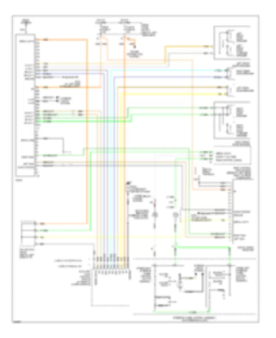
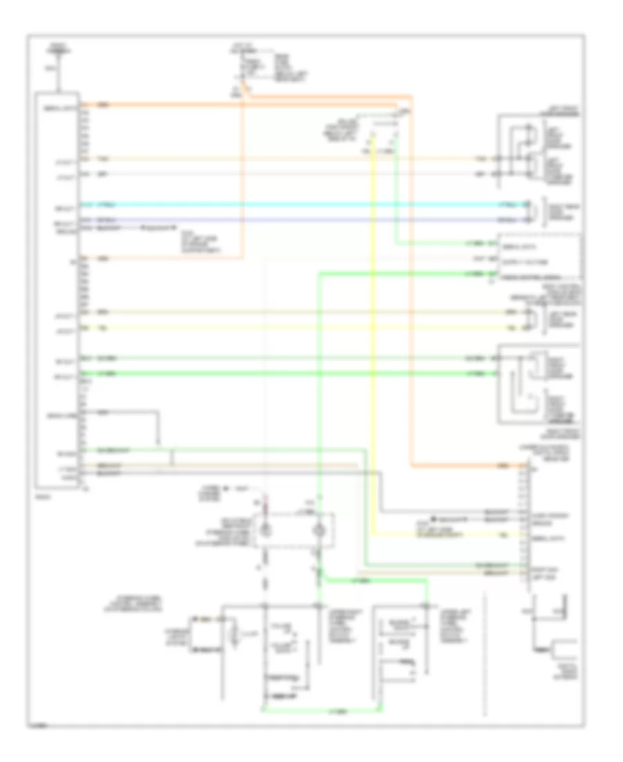
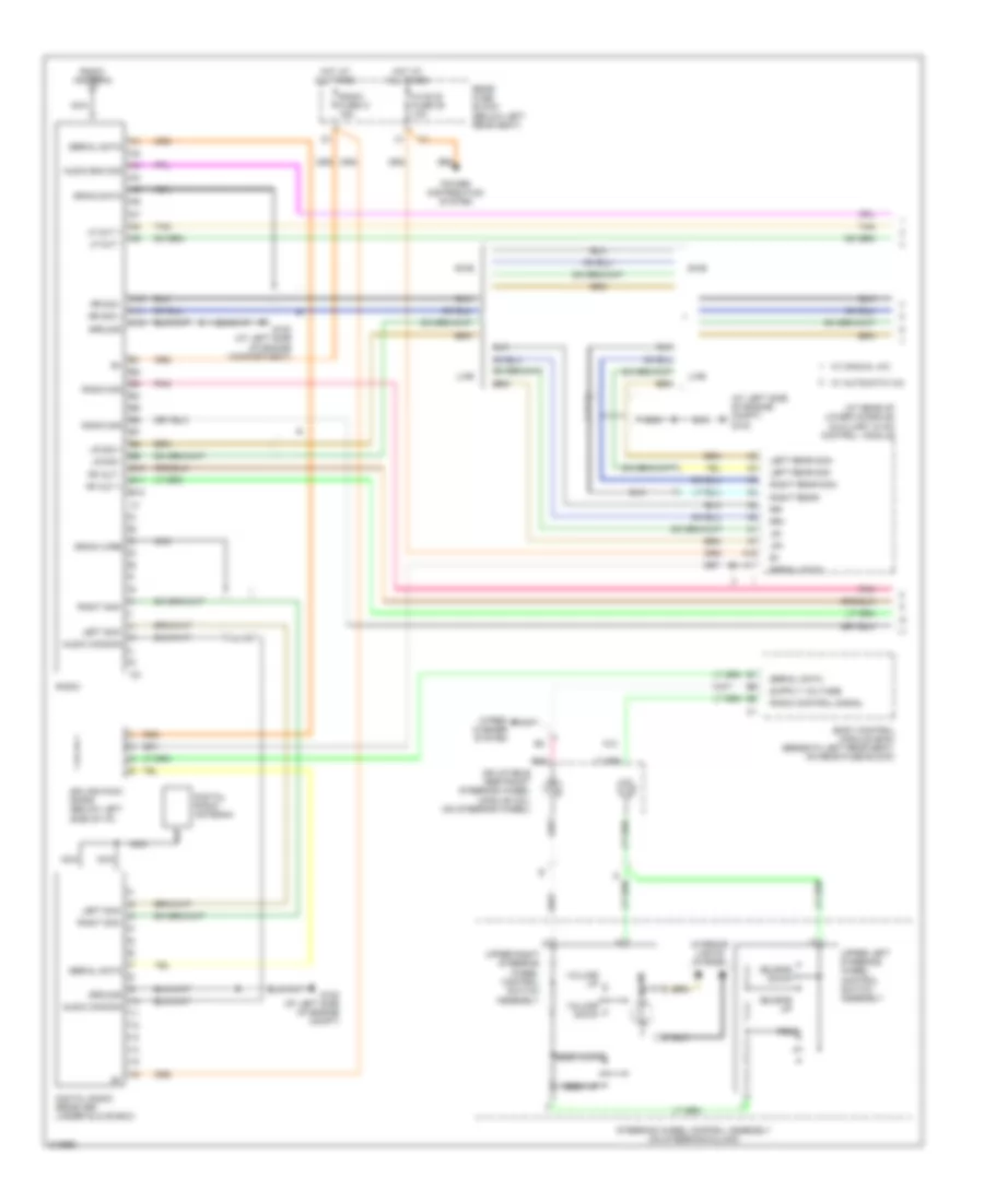
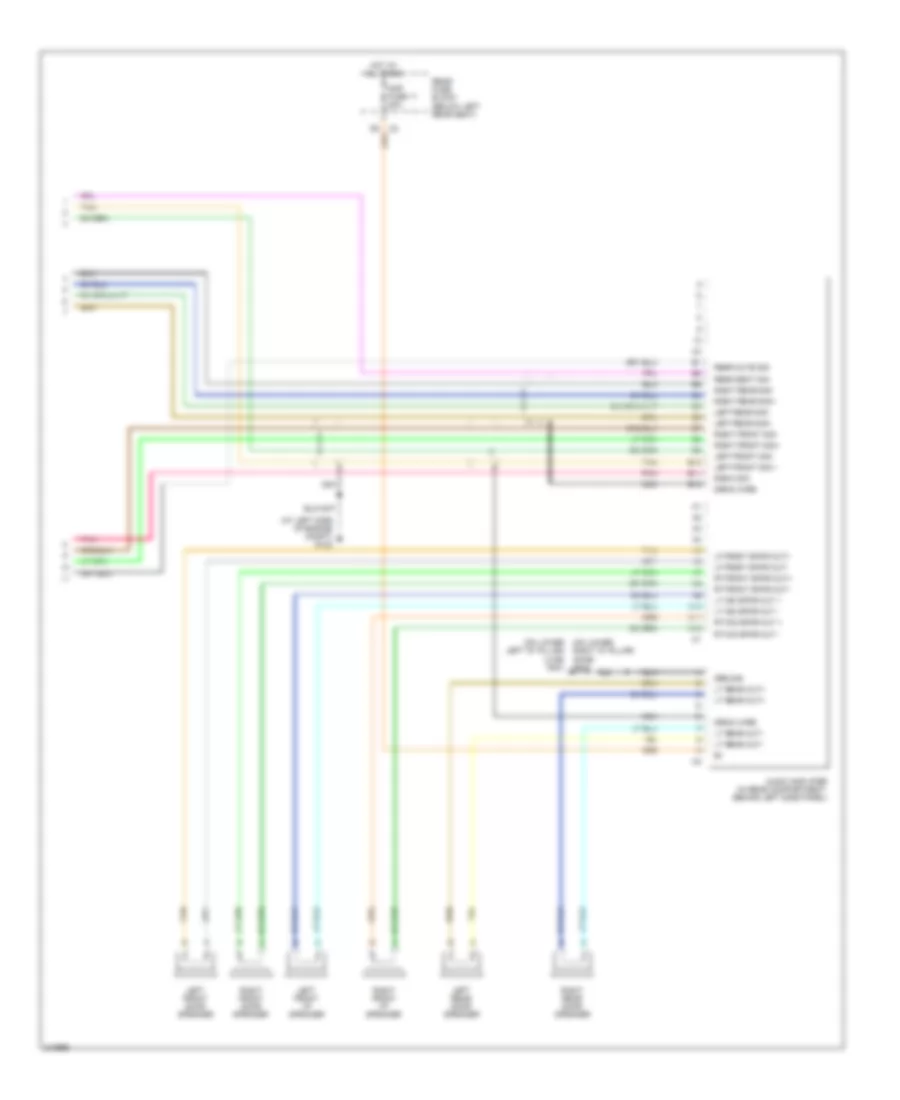
RADIO Base Radio Wiring Diagram, with Rear Seat Audio for Isuzu Ascender S 2006 List of elements for Base Radio Wiring Diagram, with Rear Seat Audio for Isuzu Ascender S 2006: 67 (lwb) w/ automatic a/c (lwb) w/ manual a/c A10 A11 A12 A16 Audio commom Auxiliary hvac control module (at rear of lower console) B10 B11 B12 B16 Body control module (bcm) (beneath left rear seat, on rear fuse block) Digital radio antenna Digital radio receiver Drain wire G102 (at left side of engine compt) G201 Ground Hot at all times Hvac b fuse 36 10a Illum Inflatable restraint steering wheel module coil Interior lights system Left front door speaker Left front door tweeter speaker Left rear door speaker Left sig+ Lf out + Lf out - Lr out + Lr out - Lr+ Lr- Nca Pnk Power distribution system Prog Radio Radio antenna Radio control signal Radio fuse 41 15a Rear fuse block (below left rear seat) Rf out + Rf out - Right front door speaker Right front door tweeter speaker Right rear door speaker Right sig+ Rr out + Rr out - Rr+ Rr- Seek down Seek up Serial data Source down Source up Sp201 (lower right center of dash) Splice pack sp205 (below left side of i/p) Steering wheel control assembly (on steering column) Tan Upper left steering wheel control switch assembly Upper right steering wheel control switch assembly Volume down Volume up Wiper/ washer system Base Radio Wiring Diagram, without Rear Seat Audio for Isuzu Ascender S 2006 List of elements for Base Radio Wiring Diagram, without Rear Seat Audio for Isuzu Ascender S 2006: 58 (under glove box) digital radio receiver A10 A11 A12 Audio Audio common B10 B11 B12 Body control module (bcm) (beneath left rear seat, on rear fuse block) Digital radio antenna Drain wire G102 (at left side of engine compartment) G102 (at left side of engine compt) Ground Hot at all times Illum Inflatable restraint steering wheel module coil (on steering wheel) Interior lights system Left front door speaker Left front door tweeter speaker Left rear door speaker Left sig+ Lf out + Lf out - Lr out + Lr out - Lt sig+ Nca Pnk Prog Radio Radio antenna Radio control signal Radio fuse 41 15a Rear fuse block (below left rear seat) Rf out + Rf out - Rh sig+ Right front door speaker Right front door tweeter speaker Right rear door speaker Right sig+ Rr out + Rr out - Seek down Seek up Serial data Source down Source up Splice pack sp205 (below left side of i/p) Steering wheel control assembly (on steering column) Tan Upper left steering wheel control switch assembly Upper right steering wheel control switch assembly Volume down Volume up Wiper/ washer system Premium Radio Wiring Diagram (1 of 2) for Isuzu Ascender S 2006 List of elements for Premium Radio Wiring Diagram (1 of 2) for Isuzu Ascender S 2006: 70 (at left side of engine compt) g102 (at rear of lower console) A10 A11 A12 A16 Audio common Audio ena sig Auxiliary hvac control module B10 B11 B12 Body control module (bcm) (beneath left rear seat, on rear fuse block) Digital radio antenna Digital radio receiver (under glove box) Drain data Drain wire G102 (at left side of engine compartment) G102 (at left side of engine compt) Ground Hot at all times Hvac b fuse 36 10a Illum Inflatable restraint steering wheel module coil (on steering wheel) Interior lights system Left rear sig+ Left rear sig- Left sig+ Lf out + Lf out - Lr sig + Lr sig - Lr+ Lr- Lwb Nca Pnk Power distribution system Prog Radio Radio antenna Radio control signal Radio fuse 41 15a Radio sig Rear fuse block (below left rear seat) Rf out + Rf out - Right rear sig+ Right rear- Right sig+ Rr sig + Rr sig - Rr+ Rr- Seek down Seek up Serial data Source down Source up Splice pack sp205 (below left side of i/p) Steering wheel control assembly (on steering column) Swb Tan Upper left steering wheel control switch assembly Upper right steering wheel control switch assembly Volume down Volume up W/ automatic a/c W/ manual a/c Wiper/ washer system Premium Radio Wiring Diagram (2 of 2) for Isuzu Ascender S 2006 List of elements for Premium Radio Wiring Diagram (2 of 2) for Isuzu Ascender S 2006: 46 (at left side of engine compt) g102 (on lower left "d" pillar) (lwb) g401 (on lower right "d" pillar) (swb) g402 A a A10 A11 A12 Amp fuse 11 20a Audio amplifier (in rear compartment, behind left side panel) B10 B11 B12 Drain wire Ground Hot at all times Left front door speaker Left front i/p speaker Left front sig + Left front sig- Left rear door speaker Left rear sig+ Left rear sig- Lf front spkr out+ Lf front spkr out- Lt mid spkr out + Lt mid spkr out - Lt rear out+ Lt rear out- Nca Pnk Radio sig Rear fuse block (below left rear seat) Rear mute sig Rear seat sig Right front door speaker Right front i/p speaker Right front sig+ Right front sig- Right rear door speaker Right rear sig+ Right rear sig- Rt front spkr out+ Rt front spkr out- Rt mid spkr out + Rt mid spkr out - Tan
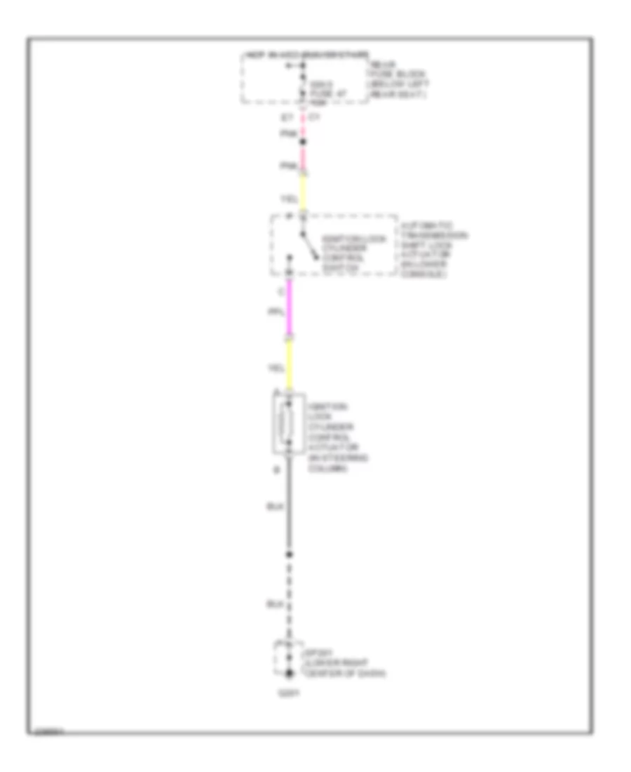
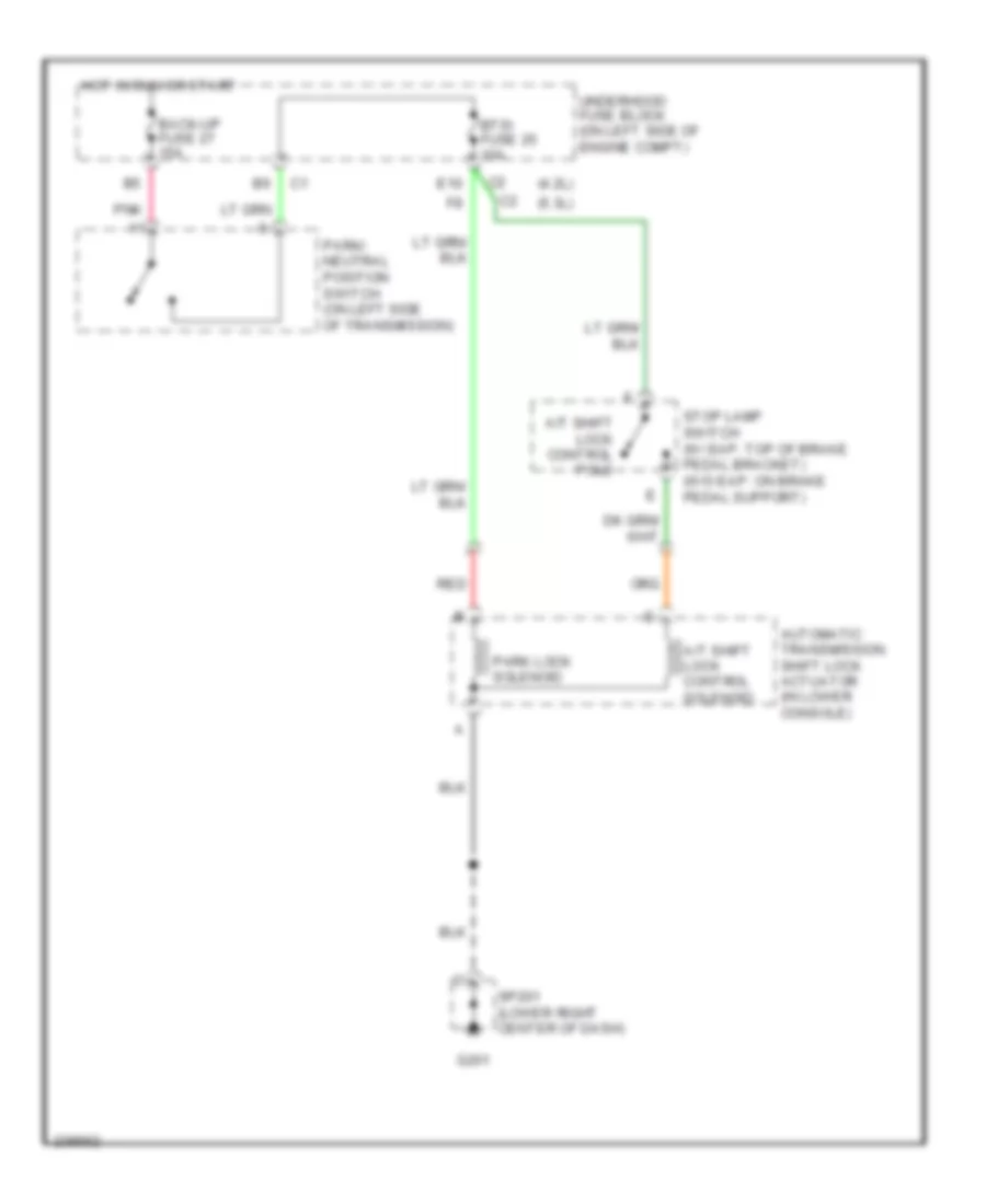
SHIFT INTERLOCK Ignition Lock Solenoid Wiring Diagram for Isuzu Ascender S 2006 List of elements for Ignition Lock Solenoid Wiring Diagram for Isuzu Ascender S 2006: 9 Automatic transmission shift lock actuator (in lower console) G201 Hot in acc, run or start Ign 0 fuse 47 10a Ignition lock cylinder control actuator (in steering column) Ignition lock cylinder control switch Pnk Rear fuse block (below left rear seat) Sp201 (lower right center of dash) Shift Interlock Wiring Diagram for Isuzu Ascender S 2006 List of elements for Shift Interlock Wiring Diagram for Isuzu Ascender S 2006: 17 (4.2l) (5.3l) A/t shift lock control pole A/t shift lock control solenoid Automatic transmission shift lock actuator (in lower console) Back-up fuse 27 15a Btsi fuse 25 10a E10 G201 Hot in run or start Park lock solenoid Park/ neutral position switch (on left side of transmission) Pnk Red Sp201 (lower right center of dash) Stop lamp switch (w/ eap: top of brake pedal bracket) (w/o eap: on brake pedal support) Underhood fuse block (on left side of engine compt)
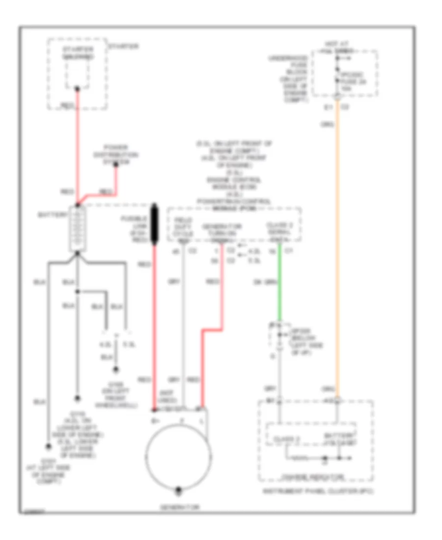
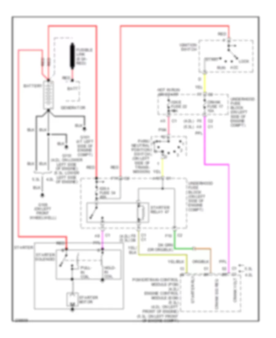
STARTING/CHARGING Charging Wiring Diagram for Isuzu Ascender S 2006 List of elements for Charging Wiring Diagram for Isuzu Ascender S 2006: 25 (5.3l: on left front of engine compt) (4.2l: on left front of engine) (5.3l) engine control module (ecm) (4.2l) powertrain control module (pcm) (not used) 4.2l 5.3l Battery Battery voltage Charge indicator Class 2 Class 2 serial data Field duty cycle sig Fusible link (8 ga- red) G101 (at left side of engine compt) G106 (on left front wheelwell) G110 (4.2l: on lower left side of engine) (5.3l: lower left side of engine) Generator Generator turn on signal Hot at all times Instrument panel cluster (ipc) Ipc/dic fuse 24 10a Power distribution system Red Sp205 (below left side of i/p) Starter Starter solenoid Underhood fuse block (on left side of engine compt) Starting Wiring Diagram for Isuzu Ascender S 2006 List of elements for Starting Wiring Diagram for Isuzu Ascender S 2006: 40 (4.2l) (4.2l) (5.3l) (5.3l) 4.2l 5.3l A10 Acc Batt Battery C1 c1 Crank fuse 17 10a Crank sig req Crank volt F10 F11 F8 d8 Fusible link (8 ga- red) G101 (at left side of engine compt) G106 (on left front wheelwell) G110 (4.2l: on lower left side of engine) (5.3l: lower left side of engine) Generator Hold- in coil Hot in run or start Ign a fuse 34 40a Ign e fuse 22 10a Ignition switch Lock Park/ neutral position switch (on left side of trans- mission) Pnk Powertrain control module (pcm) (4.2l) engine control module (ecm) (5.3l) (4.2l: on left front of engine) (5.3l: on left front of engine compt) Pull- in coil Red Run Start Starter Starter motor Starter relay 47 Starter rly Starter solenoid Underhood fuse block (on left side of engine compt)
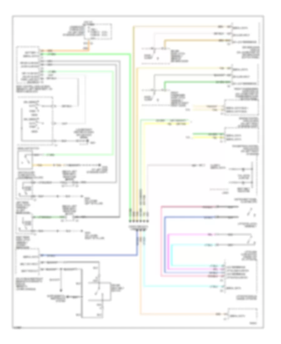
SUPPLEMENTAL RESTRAINTS Supplemental Restraints Wiring Diagram (1 of 2) for Isuzu Ascender S 2006 List of elements for Supplemental Restraints Wiring Diagram (1 of 2) for Isuzu Ascender S 2006: 45 (at left side of engine compt) g102 (in left front door) (in right front door) Bar Case ground Class 2 serial Data link Driver seat belt switch G102 (at left side of engine compt) Gnd Ground High control High sensor Hot in run or start Ign 1 Ignition Inflatable restraint sensing & diagnostic module (below rear of center console) Left electronic frontal sensor (efs) Left inflatable restraint roof rail module (at left "b" pillar) Left inflatable restraint seat position sensor (sps) (under left front seat) Left inflatable restraint side impact sensor (sis) Left seat belt pretensioner (in left front seat back) Left seat belt sw Low control Nca Passenger seat belt switch Pnk Red Right electronic frontal sensor (efs) Right inflatable restraint roof rail module (at right "b" pillar) Right inflatable restraint seat position sensor (sps) (under right front seat) Right inflatable restraint side impact sensor (sis) Right seat belt pretensioner (in right front seat back) Right seat belt sw Right signal Rollover sensor Sensor return Serial data link Shorting Shorting bar Signal Sir fuse 18 10a Tan Underhood fuse block (on left side of engine compartment) Voltage Supplemental Restraints Wiring Diagram (2 of 2) for Isuzu Ascender S 2006 List of elements for Supplemental Restraints Wiring Diagram (2 of 2) for Isuzu Ascender S 2006: 43 (under right side Air bag indicator Air bag off ind Air bag on ind B12 Bar shorting Class 2 serial data Data link connector (dlc) (partial) (below dash, above accelerator pedal) E12 G102 (at left side engine compt) Gnd Hot in run or start Ign Ign 1 voltage Ign e fuse 22 10a Inflatable restraint front passenger presence system (pps) module (under front passenger's seat) Inflatable restraint i/p module (right side of i/p) Inflatable restraint passenger air bag on/off indicator Inflatable restraint passenger presence system (pps) sensor Inflatable restraint passenger seat belt tension retractor Inflatable restraint steering wheel module (on steering wheel) Inflatable restraint steering wheel module coil Inside rearview mirror Instrument panel cluster (ipc) Logic Low ref Nca Off Pnk Rear fuse block (below left rear seat) Red Sensor Sensor sig Serial data Shorting bar Side passenger's seat) Sp205 (below left side of i/p) Stage 1 Stage 2 Tan Underhood fuse block (on left side of engine compartment) Voltage ref W/ occupant sensor
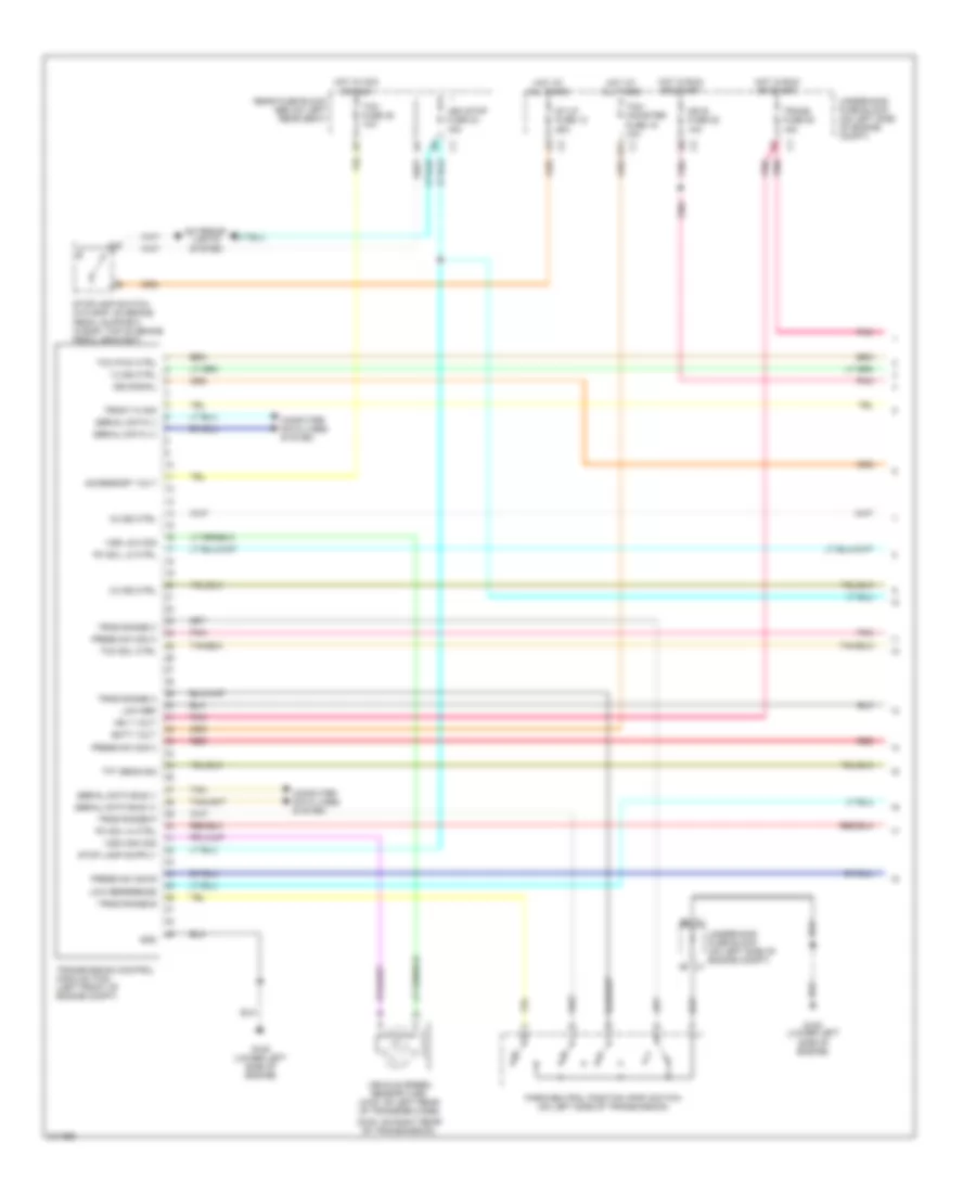
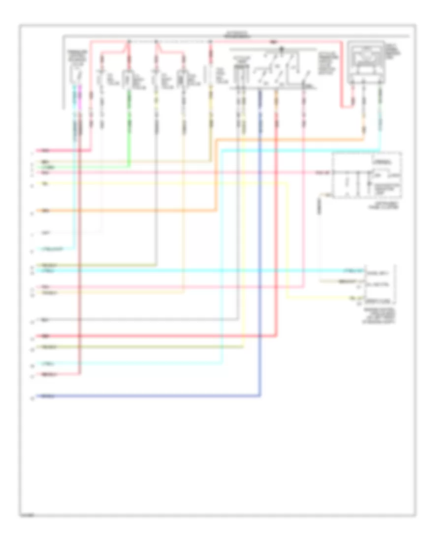
TRANSMISSION Transfer Case Wiring Diagram for Isuzu Ascender S 2006 List of elements for Transfer Case Wiring Diagram for Isuzu Ascender S 2006: 67 (4.2l: on lower left side of engine) (5.3l: lower left side of engine) (below dash, above accelerator pedal) data link connector +5v ref 2wd 2wd ind 4 hi 4 hi ind 4 lo 4 lo ind 4.2l 4wd fuse 48 15a 4wd lo sig 5.3l Afwd Afwd ind Atc fuse 8 30a Axle act Axle sw B11 Battery Brake C2 a11 Class 2 data E11 E5 c3 Encoder Encoder sig Front axle actuator (lower right front of engine, on oil pan) Front sig hi Front sig lo Front transfer case propshaft speed sensor (on left rear of transfer case) G102 (at left side of engine compt) G105 (at left side of engine compt) G107 Ground Hot at all times Hot in run Hot in run or start Illum Ing e fuse 22 10a Instrument panel cluster (ipc) Interior lights system Lock sol Logic Low ref Motor Motor ctrl a Motor ctrl b Neut Neutral Neutral ind Pnk Powertrain control module (4.2l) engine control module (5.3l) (4.2l: on left front of engine) (5.3l: on left front of engine compt) Rear fuse block (below left rear seat) Rear sig hi Rear sig lo Rear transfer case propshaft speed sensor (on right rear of transfer case) Red Service 4wd Splice pack sp205 (below left side of i/p) Sw sig Tan Transfer case Transfer case shift control module (behind left lower dash) Transfer case shift control switch Under- hood fuse block (on left side of engine compt) Underhood fuse block (on left side of engine compt)
4.2L 4.2L, A/T Wiring Diagram for Isuzu Ascender S 2006 List of elements for 4.2L, A/T Wiring Diagram for Isuzu Ascender S 2006: 94 1-2 shift red solenoid valve 2-3 shift red solenoid valve 3-2 shift red solenoid valve 4wd circuit (w/ 2-spd transfer case) 4wd lo Accelerator pedal position sensor (w/ eap: under left side of i/p) (w/o eap: on accelerator bracket) App 1 +5v App 1 lo App 1 sig App 2 +5v App 2 lo App 2 sig Automatic trans- mission fluid pressure manual valve position switch Automatic transmission Automatic transmission fluid temperature sensor B10 Battery Body control module (bcm) (beneath left rear seat, on rear fuse block) C2 a7 Class 2 data D2 c1 D2 sw D3 sw D4 sw Data link connector (below dash, above accelerator pedal) E3 c2 E3 c3 Ect ref Ect sig Electronic brake control module (on inner left frame rail, adjacent to transmission) Engine controls system Engine coolant temperature sensor (on left front of engine, near generator) Etc fuse 23 10a Exterior lights system F14 G108 (on lower left side of engine) Ground Hot at all times Hot in acc, run or start Hot in run or start Ign 0 fuse 47 10a Ignition Ignition 1 Ing e fuse 22 10a Instrument panel cluster (ipc) Lo sw Mil ind P r n d Park/neutral position switch (on left side of transmission) Pcm 1 fuse 28 15a Pcm b fuse 10 20a Pcs sol (hi) Pcs sol (lo) Pnk Powertrain control module (on left front of engine) Pressure control solenoid valve Prndl a in Prndl b in Prndl c in Prndl p in Rear fuse block (below left rear seat) Red Rev sw Service engine soon Sol (3-2) Solenoid valve Splice pack sp205 (below left side of i/p) Ss (1-2) Ss (2-3) Stoplamp in Stoplamp switch (w/ eap: top of brake pedal bracket) (w/o eap: on brake pedal support) Tan Tcc Tcc brake sw Tcc pmw red Tcc pwm Tcc red Tfp sw a Tfp sw b Tfp sw c Tft ref Tft sig Throttle body Tp 1 +5v Tp 1 lo Tp 1 sig Tp 2 +5v Tp 2 lo Tp 2 sig Underhood fuse block (on left side of engine compt) Veh stop fuse 34 15a Vehicle speed sensor (2wd: on right rear of transmission) (4wd: on left rear of transfer case) Vss (hi) Vss (lo)
5.3L 5.3L, A/T Wiring Diagram (1 of 2) for Isuzu Ascender S 2006 List of elements for 5.3L, A/T Wiring Diagram (1 of 2) for Isuzu Ascender S 2006: 54 (2wd: on right rear of transmission) 1-2 ss ctrl 2-3 ss ctrl 3-2 ss ctrl Accessory volt B11 Batt volt Computer data lines system Exterior lights system Front hi sig G108 (lower left side of engine) Gnd Hot at all times Hot in acc or run Hot in run or start Ign 1 volt Ign e fuse 22 10a Iss signal Low ref Low reference Park/neutral position (pnp) switch (on left side of transmission) Pc sol hi ctrl Pc sol lo ctrl Pnk Pnk pnk Press sw sig a Press sw sig b Press sw sig c Rear fuse block (below left rear seat) Red Serial data (+) Serial data (-) Serial data bus (+) Serial data bus (-) St/lp fuse 12 25a Stoplamp switch (w/o eap: on brake pedal support) (w/eap: top of brake pedal bracket) Tan Tcc pwm ctrl Tcc sol ctrl Tcm fuse 35 10a Tcm/ canister fuse 15 10a Tft sens sig Trans fuse 53 15a Transmission control module (tcm) (left front of engine compt) Trns range a Trns range b Trns range c Trns range p Underhood fuse block (on left side of engine compt) Underhood fuse block (on left side of engine compt) c1 Veh stop fuse 34 15a Vehicle speed sensor (vss) (4wd: on left rear of transfer case) Vss high sig Vss low sig 5.3L, A/T Wiring Diagram (2 of 2) for Isuzu Ascender S 2006 List of elements for 5.3L, A/T Wiring Diagram (2 of 2) for Isuzu Ascender S 2006: 23 1-2 shift sol valve 2-3 shift sol valve 3-2 sol valve A/t fluid pressure manual valve position switch A/t fluid temp sensor Automatic transmission Chmsl sply Engine control module (ecm) (on left front of engine compt) Front hi sig Ign Input speed sensor (iss) Instrument panel cluster Logic Malfunction indicator lamp Mil ind ctrl Pnk Pressure control solenoid valve Prnd321 Red Rev Tan Tcc pwm sol valve Tcc sol valve
WARNING SYSTEMS Chime Wiring Diagram for Isuzu Ascender S 2006 List of elements for Chime Wiring Diagram for Isuzu Ascender S 2006: 64 (4.2l) (5.3l) (below left rear seat) rear fuse block (lower right center of dash) splice pack sp201 (or tan) 10a 4.2l 5.3l A12 Auto B10 Battery + Belt sw input Body control module (bcm) (beneath left rear seat, on rear fuse block) Class 2 serial data Computer data lines system Door ajar Dr ajar input Driver door latch assembly (rear of driver's door) Driver seat belt switch Driver's door module (on lower part of driver's door switch panel) Drl defeat E12 c2 Engine control module (ecm) (on left front of engine compt) F10 Front passenger door latch assembly (rear of right front door) Front passenger's door module (on lower part of passenger's door switch panel) G102 (at left side of engine compt) G201 G302 (on lower left "b" pillar) G303 (on lower right "b" pillar) Hdlmp on sig Head Headlamp switch Hot at all times Ignition & key alarm switch (in steering column) Inflatable restraint sensing & diagnostic module (beneath lower console) Instrument panel cluster (ipc) Key in ign sw Left rear door latch assembly (in left rear door) Liftgate ajar sw Liftgate latch assembly Liftgate module (inside liftgate) Liftglass ajar sw Liftglass ajar switch (inside top of liftgate) Logic Low reference Lr dr ajar sig Nca Park Park lamp sw on input Powertrain control module (pcm) (on left front of engine) Radio Right rear door latch assembly (in right rear door) Rr dr ajar sig Seat belt indicator Seat pos out Serial data Serial data bus + Serial data bus - Sw low reference Tail gate ajar ind Tan Tbc 1 fuse 31 fuse 58 Underhood fuse block (on left side of engine compt) Liftgate Ajar Warning Wiring Diagram for Isuzu Ascender S 2006 List of elements for Liftgate Ajar Warning Wiring Diagram for Isuzu Ascender S 2006: 33 12v B5 c2 Battery Class 2 Defog sply volt Defogger system Door ajar Door locks system G401 (on lower left "d" pillar) Ground Hot at all times Instrument panel cluster (ipc) Key buzzer Lgm 2 fuse 3 30a Lgm/dsm fuse 19 10a Liftgate latch assembly Liftgate module (lgm) (inside liftgate) Liftglass ajar switch (inside top of liftgate) Lock ctrl Logic Low ref Nca Open sw sig Rear fuse block (below left rear seat) Serial data Sp205 (below left side of i/p) Sp306 (under right rear seat) Sw sig Tailgate ajar Tan Unlock ctrl Wiper motor sig Wiper/washer system
WIPER/WASHER Front Wiper/Washer Wiring Diagram for Isuzu Ascender S 2006 List of elements for Front Wiper/Washer Wiring Diagram for Isuzu Ascender S 2006: 50 (at right rear of engine compt) g103 A12 Acc voltage Accessory voltage B12 Body control module (bcm) (beneath left rear seat, on rear fuse block) Class 2 serial data Computer data lines system D10 Frt wpr fuse 33 25a G102 (at left side of engine compt) G103 (at right rear of engine compt) G105 (at left side of engine compt) G302 (on lower left "b" pillar) Ground High Hot at all times Hot in acc or on Hot in on or start Ign 1 volt Ign fuse 22 10a Instrument panel cluster (ipc) Lo delays mist Logic Low washer fluid Lsd Mist Off Outside moisture sensor (center of windshield) Outside moisture sensor signal 1 Pnk Pulse Rain fuse 29 10a Rear fuse block (below left rear seat) Red Sensor signal 1 Tan Turn signal/ multifunction switch Underhood fuse block (on left side of engine compt) Wash Windshield washer fluid level switch (in engine compt, mounted on fluid reservoir) Windshield washer fluid pump (in engine compt, attached to fluid reservoir) Windshield washer relay ctrl Windshield wiper motor (under cowl cover) Windshield wiper switch high signal Windshield wiper switch signal 1 Windshield wiper switch signal 2 Windshield wiper/ washer switch Wsw fuse 9 15a Wsw relay 42 Rear Wiper/Washer Wiring Diagram for Isuzu Ascender S 2006 List of elements for Rear Wiper/Washer Wiring Diagram for Isuzu Ascender S 2006: 33 (under right rear seat) sp306 12 volt reference Battery positive voltage Body control module (bcm) (beneath left rear seat, on rear fuse block) Class 2 ser data Cont Dly 1 Dly 2 G103 (at right rear of engine compt) G401 (on lower left "d" pillar) Hot at all times Illumination Interior lights system Liftgate module (inside liftgate) Logic Off Rear fuse block (below left rear seat) Rear window motor speed signal Rear window mtr speed signal c2 Rear window washer fluid pump (in engine compt, attached to fluid reservoir) Rear window washer relay ctrl Rear window wiper motor (inside liftgate) Rear window wiper sw sig Rear window wiper/washer switch Rear wpr relay 38 Rr wiper circuit breaker 9 15a Sound systems Sp205 (below left side of i/p) Underhood fuse block (on left side of engine compt) W/ steering wheel controls W/o steering wheel controls Wash Wpr fuse 7 20a