Diagram sections — 28 (59 total)
AIR CONDITIONING ANTI-LOCK BRAKES ANTI-THEFT BODY COMPUTER COMPUTER DATA LINES COOLING FAN CRUISE CONTROL DEFOGGERS ELECTRONIC SUSPENSION ENGINE PERFORMANCE EXTERIOR LIGHTS GROUND DISTRIBUTION HEADLIGHTS HORN INSTRUMENT CLUSTER INTERIOR LIGHTS POWER DISTRIBUTION POWER DOOR LOCKS POWER MIRRORS POWER SEATS POWER TOP/SUNROOF POWER WINDOWS RADIO SHIFT INTERLOCKS STARTING/CHARGING SUPPLEMENTAL RESTRAINTS WARNING SYSTEMS WIPER/WASHER
AIR CONDITIONING
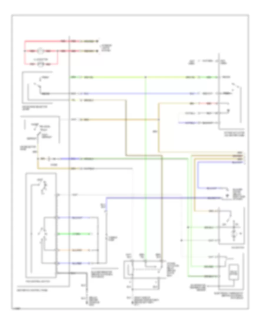
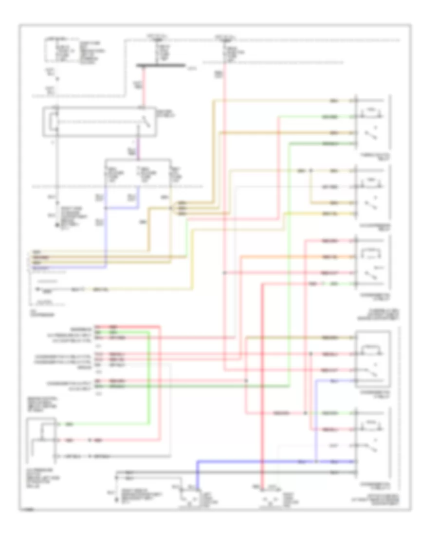
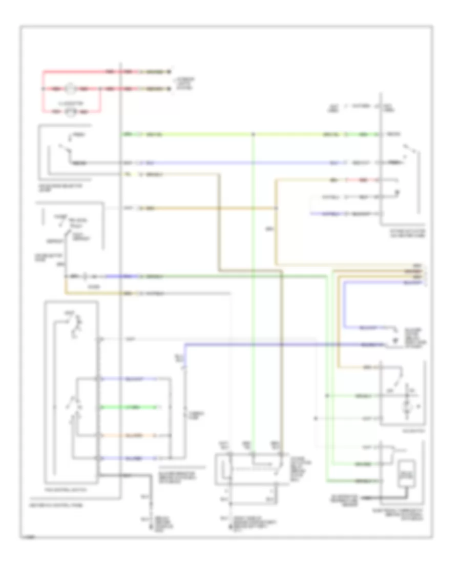
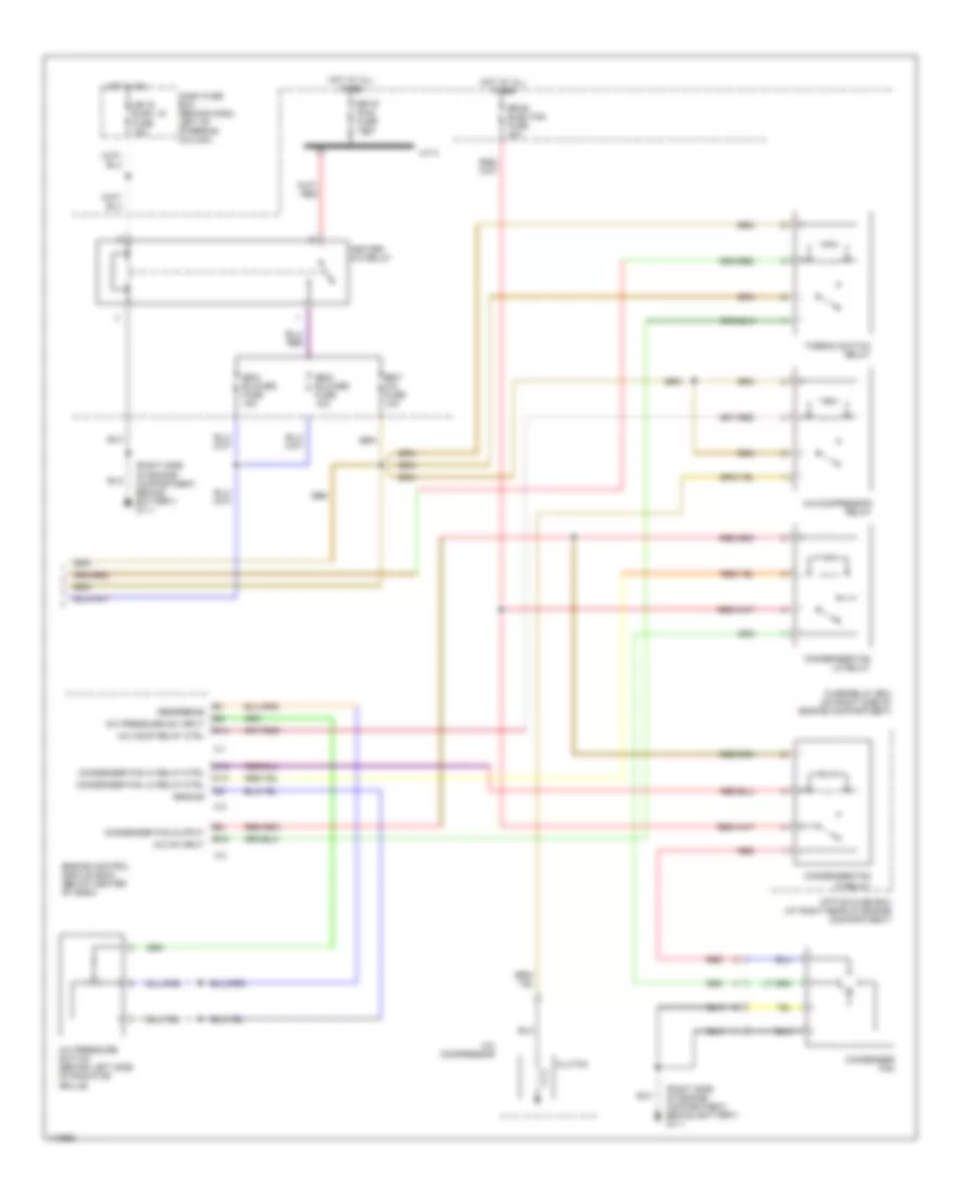
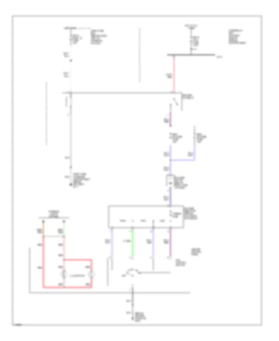
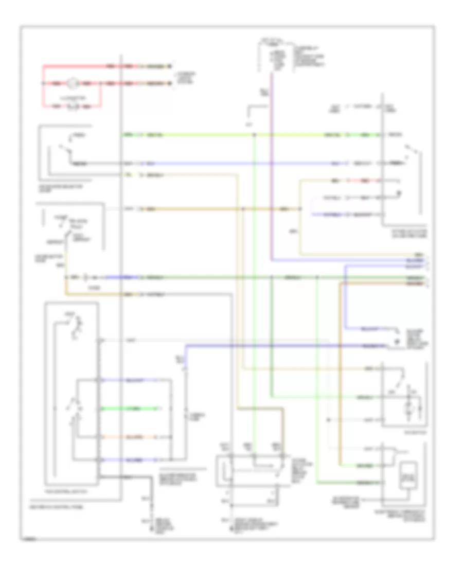
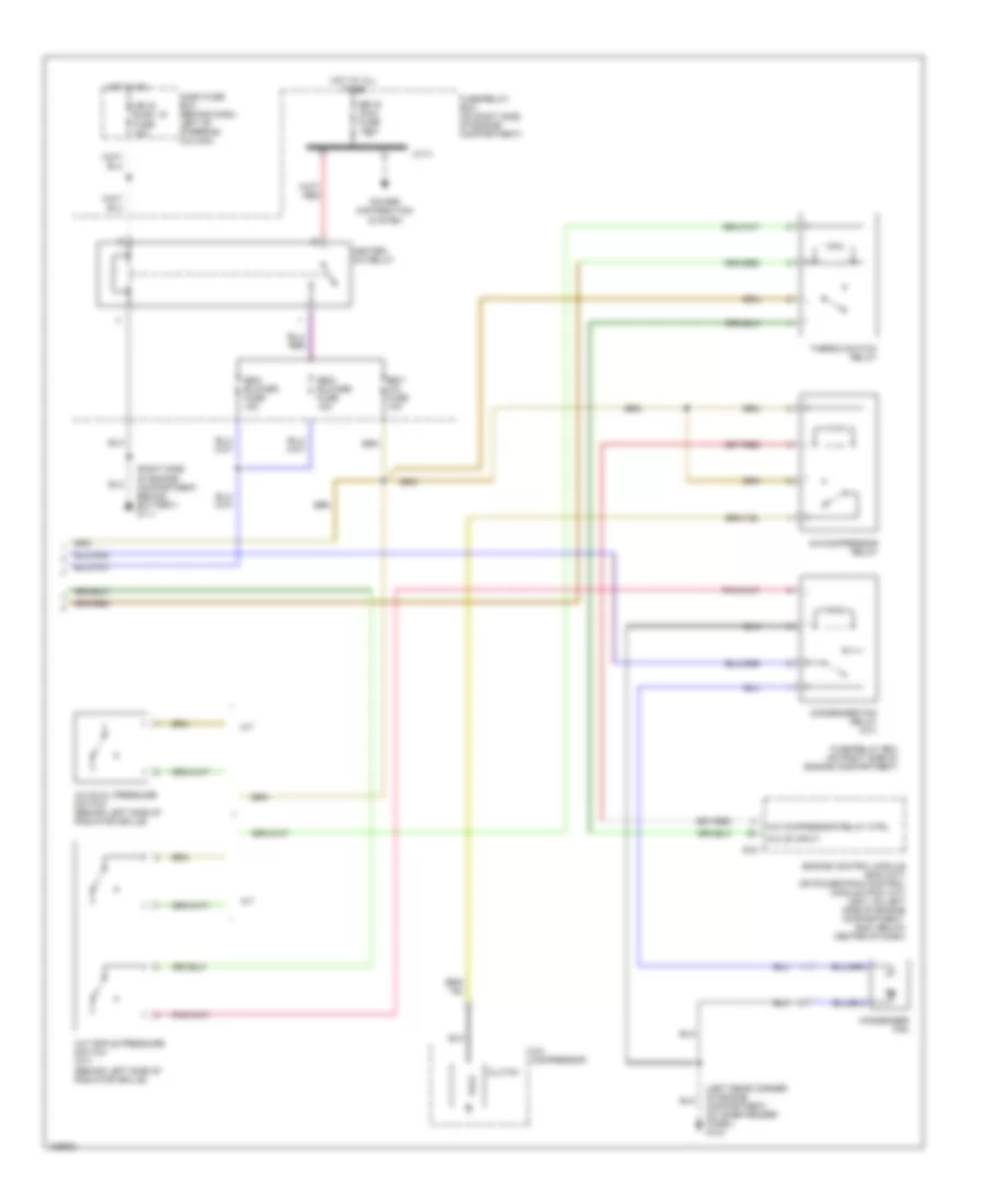
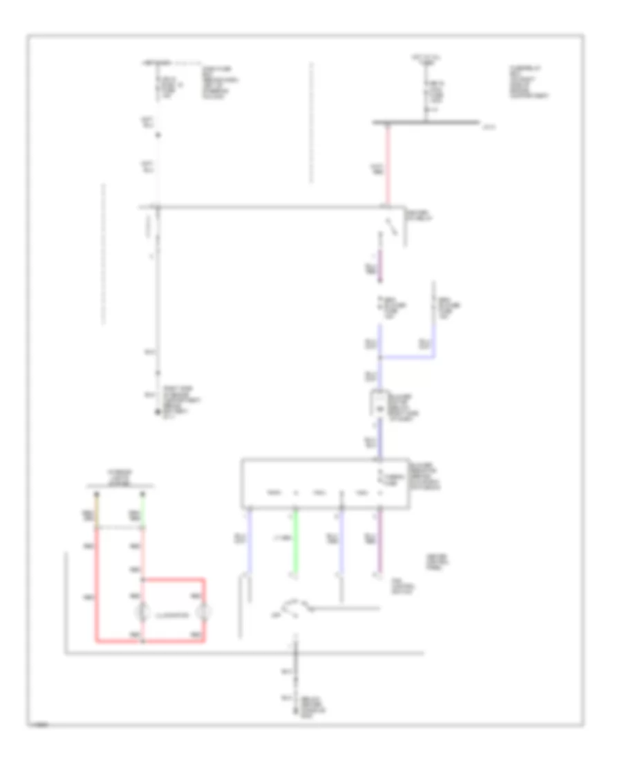
2.2L 2.2L, Manual A/C Wiring Diagram, A/T (1 of 2) for Isuzu Rodeo LSE 2001 List of elements for 2.2L, Manual A/C Wiring Diagram, A/T (1 of 2) for Isuzu Rodeo LSE 2001: 28 (below center console) g302 (not used) (right side of engine compartment, behind battery) g111 A/c switch Air selector knob Air source selector lever Bi-level Blower motor (below right side of dash) Blower resistor (behind glove box, on plenum) Defrost Diode Electronic thermostat (behind glove box, on plenum) Evaporator temperature sensor Face Fan control switch Foot Foot/ defrost Fresh Heater-a/c control panel Illumination Intake actuator (on heater case) Intake actuator relay (behind glove box) Interior lights system Off Recirc Red Solid state Thermo fuse 2.2L, Manual A/C Wiring Diagram, A/T (2 of 2) for Isuzu Rodeo LSE 2001 List of elements for 2.2L, Manual A/C Wiring Diagram, A/T (2 of 2) for Isuzu Rodeo LSE 2001: 41 (right side of engine compartment, behind battery) g111 A/c comp relay ctrl A/c compressor A/c compressor relay A/c on input A/c pressure sw input A/c pressure switch (behind left side of radiator grille) B14 C-1 C-2 C-3 C12 C13 Cb-15 elec. ig fuse 15a Clutch Condenser fan hi relay Condenser fan hi relay 2 Condenser fan hi relay ctrl Condenser fan lo relay Condenser fan lo relay ctrl Condenser fan output Dash fuse box (behind dash, left of steering column) E15 Eb-16 main fuse 100a Eb-20 elec fan fuse 40a Eb-5 blower fuse 15a Eb-6 blower fuse 15a Eb-7 a/c fuse 10a Engine control module (ecm) (below center of dash) Fuse/relay box (on right side of engine compartment) Ground Heater- a/c relay Hot at all times Hot in on J/c a Left hand cooling fan Option fuse box (at right rear of engine compartment) Red Reference Right hand cooling fan Thermo switch relay 2.2L, Manual A/C Wiring Diagram, M/T (1 of 2) for Isuzu Rodeo LSE 2001 List of elements for 2.2L, Manual A/C Wiring Diagram, M/T (1 of 2) for Isuzu Rodeo LSE 2001: 29 (below center console) g302 (not used) (right side of engine compartment, behind battery) g111 A/c switch Air selector knob Air source selector lever Bi-level Blower motor (below right side of dash) Blower resistor (behind glove box, on plenum) Defrost Diode Electronic thermostat (behind glove box, on plenum) Evaporator temperature sensor Face Fan control switch Foot Foot/ defrost Fresh Heater-a/c control panel Illumination Intake actuator (on heater case) Intake actuator relay (behind glove box) Interior lights system Nca Off Recirc Red Solid state Thermo fuse 2.2L, Manual A/C Wiring Diagram, M/T (2 of 2) for Isuzu Rodeo LSE 2001 List of elements for 2.2L, Manual A/C Wiring Diagram, M/T (2 of 2) for Isuzu Rodeo LSE 2001: 39 (right side of engine compartment, behind battery) g111 A/c comp relay ctrl A/c compressor A/c compressor relay A/c on input A/c pressure sw input A/c pressure switch (behind left side of radiator grille) B14 C-1 C-2 C-3 C12 C13 Cb-15 elec. ig fuse 15a Clutch Condenser fan Condenser fan hi relay Condenser fan hi relay ctrl Condenser fan lo relay Condenser fan lo relay ctrl Condenser fan output Dash fuse box (behind dash, left of steering column) E15 Eb-16 main fuse 100a Eb-20 elec fan fuse 40a Eb-5 blower fuse 15a Eb-6 blower fuse 15a Eb-7 a/c fuse 10a Engine control module (ecm) (below center of dash) Fuse/relay box (on right side of engine compartment) Ground Heater- a/c relay Hot at all times Hot in on J/c a Option fuse box (at right rear of engine compartment) Red Reference Thermo switch relay Heater Wiring Diagram for Isuzu Rodeo LSE 2001 List of elements for Heater Wiring Diagram for Isuzu Rodeo LSE 2001: 21 (below center console) g302 (right side of engine compartment, behind battery) g111 Blower motor (below right side of dash) Blower resistor (behind glove box, on plenum) Cb-15 elec. ig fuse 15a Dash fuse box (behind dash, left of steering column) Eb-16 main fuse 100a Eb-5 blower fuse 15a Eb-6 blower fuse 15a Fan control switch Fuse/relay box (on right side of engine compartment) Heater control panel Heater- a/c relay Hot at all times Hot in on Illumination Interior lights system J/c a Off Red Thermo fuse
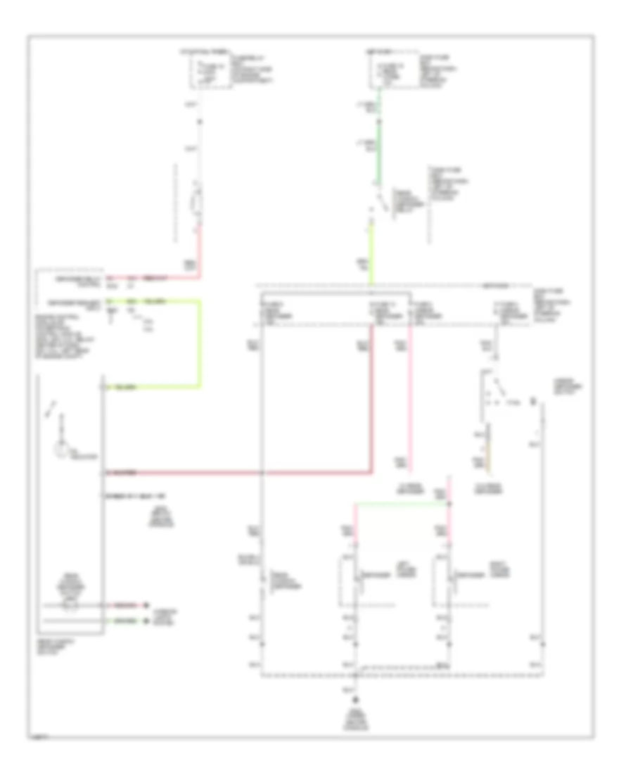
3.2L 3.2L, Manual A/C Wiring Diagram (1 of 2) for Isuzu Rodeo LSE 2001 List of elements for 3.2L, Manual A/C Wiring Diagram (1 of 2) for Isuzu Rodeo LSE 2001: 32 (below center console) g302 (not used) (right side of engine compartment, behind battery) g111 A/c switch A/t Air selector knob Air source selector lever Bi-level Blower motor (below right side of dash) Blower resistor (behind glove box, on plenum) Defrost Diode Eb-20 (cond fan) fuse 30a Electronic thermostat (behind glove box, on plenum) Evaporator temperature sensor Face Fan control switch Foot Foot/ defrost Fresh Fuse/relay box (on right side of engiine compartment) Heater-a/c control panel Hot at all times Illumination Intake actuator (on heater case) Intake actuator relay (behind glove box) Interior lights system Off Recirc Red Solid state Thermo fuse 3.2L, Manual A/C Wiring Diagram (2 of 2) for Isuzu Rodeo LSE 2001 List of elements for 3.2L, Manual A/C Wiring Diagram (2 of 2) for Isuzu Rodeo LSE 2001: 28 (left rear corner of engine compartment, on inner fender panel) g104 (right side of engine compartment, behind battery) g111 A/c compressor A/c compressor relay A/c compressor relay ctrl A/c dual pressure switch (behind left side of radiator grille) A/c on input A/c triple pressure switch (a/t) (behind left side of radiator grille) A/t Cb-15 elec. ig fuse 15a Clutch Condenser fan Condenser fan relay (a/t) Dash fuse box (behind dash, left of steering column) E-21 Eb-16 main fuse 100a Eb-5 blower fuse 15a Eb-6 blower fuse 15a Eb-7 a/c fuse 10a Engine control module (ecm) (m/t) or powertrain control module (pcm) (a/t) (2001: on left side of engine compartment, 2000: below center of dash) Fuse/relay box (on right side of engine compartment) Heater- a/c relay Hot at all times Hot in on J/c a M/t Power distribution system Thermo switch relay Heater Wiring Diagram for Isuzu Rodeo LSE 2001 List of elements for Heater Wiring Diagram for Isuzu Rodeo LSE 2001: 21 (below center console) g302 (right side of engine compartment, behind battery) g111 Blower motor (below right side of dash) Blower resistor (behind glove box, on plenum) Cb-15 elec. ig fuse 15a Dash fuse box (behind dash, left of steering column) Eb-16 main fuse 100a Eb-5 blower fuse 15a Eb-6 blower fuse 15a Fan control switch Fuse/relay box (on right side of engine compartment) Heater control panel Heater- a/c relay Hot at all times Hot in on Illumination Interior lights system J/c a Off Red Thermo fuse
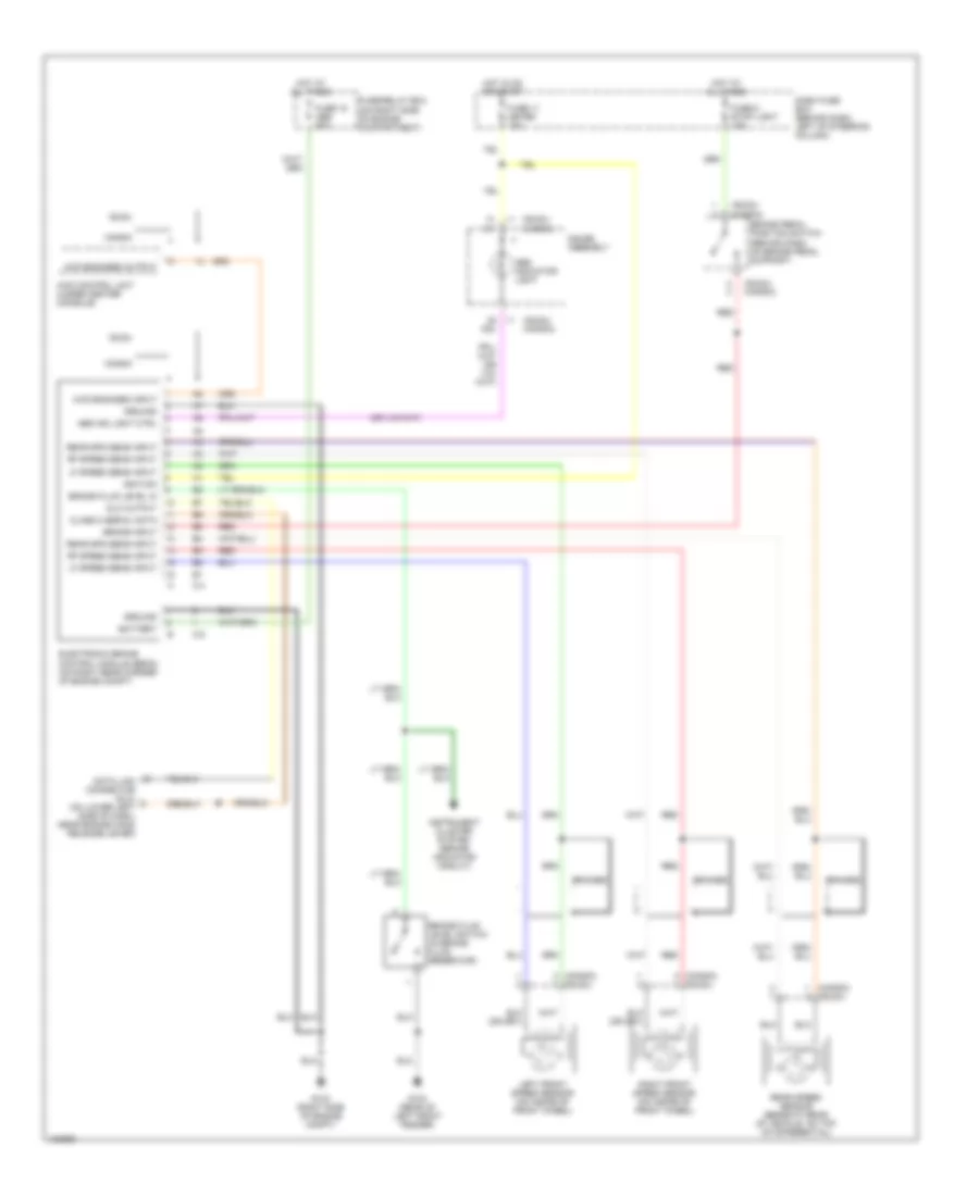
ANTI-LOCK BRAKES Anti-lock Brake Wiring Diagrams for Isuzu Rodeo LSE 2001 List of elements for Anti-lock Brake Wiring Diagrams for Isuzu Rodeo LSE 2001: 44 (honda) (isuzu) (isuzu) (honda) 4wd control unit (under center console) 4wd engaged input 4wd engaged output A23 Abs ind light ctrl Abs indicator light Battery Braided Brake fluid level in Brake fluid level switch (in brake fluid reservoir) Brake input Brake pedal position switch (behind dash, on brake pedal support) C-4 C-5 Class 2 serial data Dash fuse box (behind dash, left of steering column) Data link connector (dlc) (on lower left side of dash, near engine hood release lever) Dlc output Electronic brake control module (ebcm) (on right rear corner of engine compt) Fuse 11 meter 15a Fuse 18 abs 50a Fuse 6 stop light 15a Fuse/relay box (on right side of engine compartment) G103 (right side of engine compt) G104 (rear of left front fender) Gauge assembly Ground Honda Hot at all times Hot in on or start I-1 Ignition Instrument cluster system (brake indicator circuit) Isuzu Left front speed sensor (on inside of front wheel) Lf speed sens input Rear spd sens input Rear speed sensor (beneath rear of vehicle, on top of differential) Red Rf speed sens input Right front speed sensor (on inside of front wheel)
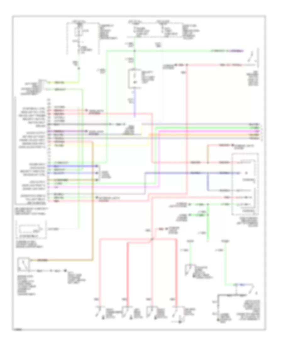
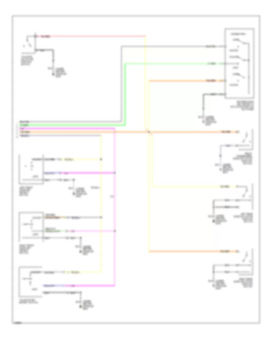
ANTI-THEFT Anti-theft Wiring Diagram (1 of 2) for Isuzu Rodeo LSE 2001 List of elements for Anti-theft Wiring Diagram (1 of 2) for Isuzu Rodeo LSE 2001: 55 (under center console) g302 Amigo Anti- theft fuse cb-20 10a Anti-theft horn (on right side of engine compartment) Ceiling light trigger Coil Dash fuse box (behind dash, left of steering column) Diode box Disarm lock input Disarm unlock input Door lock posit in Door locks system Door unlock posit in Door/hatch open in Dr door act ctrl Driver's door switch Engine hood input Engine hood switch (closed with hood open) (at right rear corner of engine compartment) Exterior lights system Front passenger's door switch Fuse/relay box (on right side of engine compartment) G111 (right side of engine compt, behind battery) G302 (under center console) Ground Hatch gate open switch (closed with hatch gate open) (inside top center of tailgate, on latch assembly) Headlight rly ctrl Headlights systems Horn fuse eb-2 10a Hot at all times Hot in acc or on Ignition input Interior lights system J/c b Key in ignition Key reminder switch (part of ignition switch) Key rod act posit Keyless entry & security control unit (above right kick panel) Left rear door switch Lock output Lock/unlock Power door lock fuse cb-7 20a Power input Red Right rear door switch Rodeo Security horn ctrl Security ind ctrl Security or anti-theft indicator light Starter relay Starter rly ctrl Tailgate open switch (left rear cargo compt) Taillight relay Unlock output Warning systems Wiper/ washer systems Anti-theft Wiring Diagram (2 of 2) for Isuzu Rodeo LSE 2001 List of elements for Anti-theft Wiring Diagram (2 of 2) for Isuzu Rodeo LSE 2001: 12 (momentary) (under center console) g302 Driver's door key detect & actuator position switches Front passenger's door actuator position switch Left front door key detect switch Left rear door actuator position switch Lock Right front door key detect switch Right rear door actuator position switch Tailgate actuator position switch Tailgate key detect switch Unlock
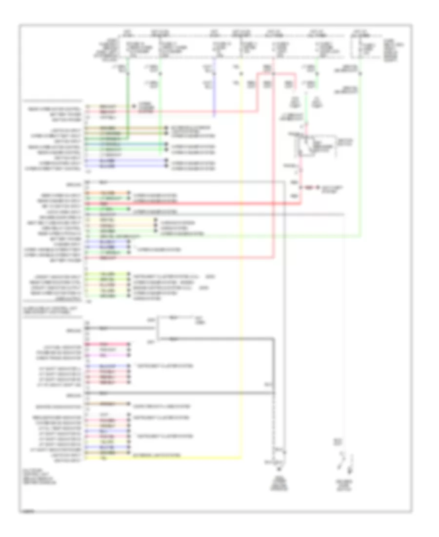
BODY COMPUTER Body Computer Wiring Diagrams for Isuzu Rodeo LSE 2001 List of elements for Body Computer Wiring Diagrams for Isuzu Rodeo LSE 2001: 78 (2000) (rodeo) A/t (p) (or m/t) shift ind A/t oil temp indicator A/t shift indicator (2) A/t shift indicator (3) A/t shift indicator (d) A/t shift indicator (l) A/t shift indicator (n) A/t shift indicator (r) A/t shift indicator power Alarm & relay control unit (above right kick panel) Anti-theft system Battery power Check trans indicator Computer data lines system Dash fuse box (behind dash, left of steering column) Driver's door open in Driver's door switch Ecm/pcm communication Engine controls system (2.2l) Exterior & interior lights system Exterior lights system Fuse 11 meter 15a Fuse 15 elec. ig. 15a Fuse 16 rear wiper & washer 10a Fuse 17 front wiper & washer 20a Fuse 2 horn 10a Fuse 5 dome light 10a Fuse 7 power door lock 20a Fuse/ relay box (right side of engine compt) G302 (under center console) Ground Hatch open input Horn output Horn relay control Horns system Hot at all times Hot in on Hot in on or start I-41 I-42 Ignition input Ignition power Ignition switch Instrument cluster system Instrument cluster system (2.2l) Key in ignition input Key reminder switch Lights on input Low fuel indicator Multiplex control unit (below rear of center console) Not used Pnk Power drive indicator Rear washer control Rear washer on input Rear wiper motor control Rear wiper motor park in Rear wiper mtr run in Rear wiper on input Rear wiper run/park ctrl Red Reduce power indicator Seat belt unbuckled input Upshift indicator input Upshift indicator output W/ anti- theft W/o anti- theft Warning systems Washer input Winter drive indicator Wiper intermittent input Wiper run/park input Wiper variable intermittent Wiper/ washer system Wiper/intermittent control Wiper/washer system
COMPUTER DATA LINES
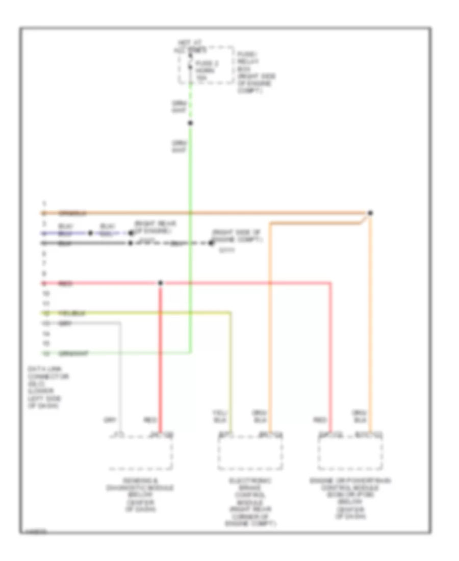
2.2L 2.2L, Computer Data Lines for Isuzu Rodeo LSE 2001 List of elements for 2.2L, Computer Data Lines for Isuzu Rodeo LSE 2001: 16 (right rear of engine) (right side of engine compt) B6 c4 C1 b13 D4 c2 Data link connector (dlc) (lower left side of dash) Electronic brake control module (right rear corner of engine compt) Engine or powertrain control module (ecm) or (pcm) (below center of dash) Fuse 2 horn 10a Fuse/ relay box (right side of engine compt) G111 G117 Hot at all times I30 Red Sensing & diagnostic module (below center of dash)
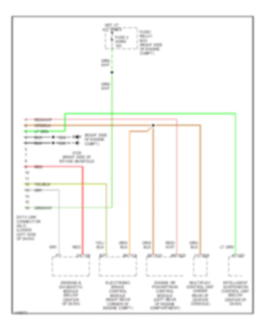
3.2L 3.2L, Computer Data Lines for Isuzu Rodeo LSE 2001 List of elements for 3.2L, Computer Data Lines for Isuzu Rodeo LSE 2001: 19 (right side of engine compt) B26 C4 b6 C52 Data link connector (dlc) (lower left side of dash) E21 E22 Electronic brake control module (right rear corner of engine compt) Engine or powertrain control module (left rear of engine compartment) Fuse 2 horn 10a Fuse/ relay box (right side of engine compt) G111 G120 (right side of intake manifold) Hot at all times I30 Intelligent suspension control unit (below center of dash) Multiplex control unit (under rear of center console) Red Sensing & diagnostic module (below center of dash)
COOLING FAN
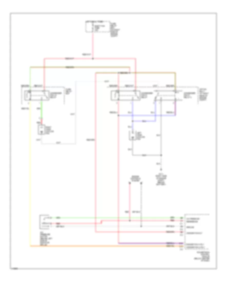
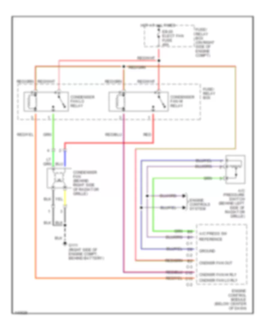
2.2L 2.2L, Cooling Fan Wiring Diagram, A/T for Isuzu Rodeo LSE 2001 List of elements for 2.2L, Cooling Fan Wiring Diagram, A/T for Isuzu Rodeo LSE 2001: 26 A/c press sw A/c pressure switch (behind left side of radiator grille) C-1 C-2 C-3 C12 C13 Cndnsr fan hi rly Cndnsr fan lo rly Cndnsr fan out Condenser fan hi relay Condenser fan hi relay 2 Condenser fan lo relay Elect fan fuse 40a Engine controls system Fuse/ relay box Fuse/ relay box (on right side of engine compt) G111 (right side of engine compt, behind battery) Ground Hot at all times Left hand cooling fan Option box 1 (at right rear of engine compt) Powertrain control module (below center of dash) Red Reference Right hand cooling fan 2.2L, Cooling Fan Wiring Diagram, M/T for Isuzu Rodeo LSE 2001 List of elements for 2.2L, Cooling Fan Wiring Diagram, M/T for Isuzu Rodeo LSE 2001: 23 A/c press sw A/c pressure switch (behind left side of radiator grille) C-1 C-2 C-3 C12 C13 Cndnsr fan hi rly Cndnsr fan lo rly Cndnsr fan out Condenser fan (behind right side of radiator grille) Condenser fan hi relay Condenser fan lo relay Eb-20 elect fan fuse 40a Engine control module (below center of dash) Engine controls system Fuse/ relay box Fuse/ relay box (on right side of engine compt) G111 (right side of engine compt, behind battery) Ground Hot at all times Red Reference
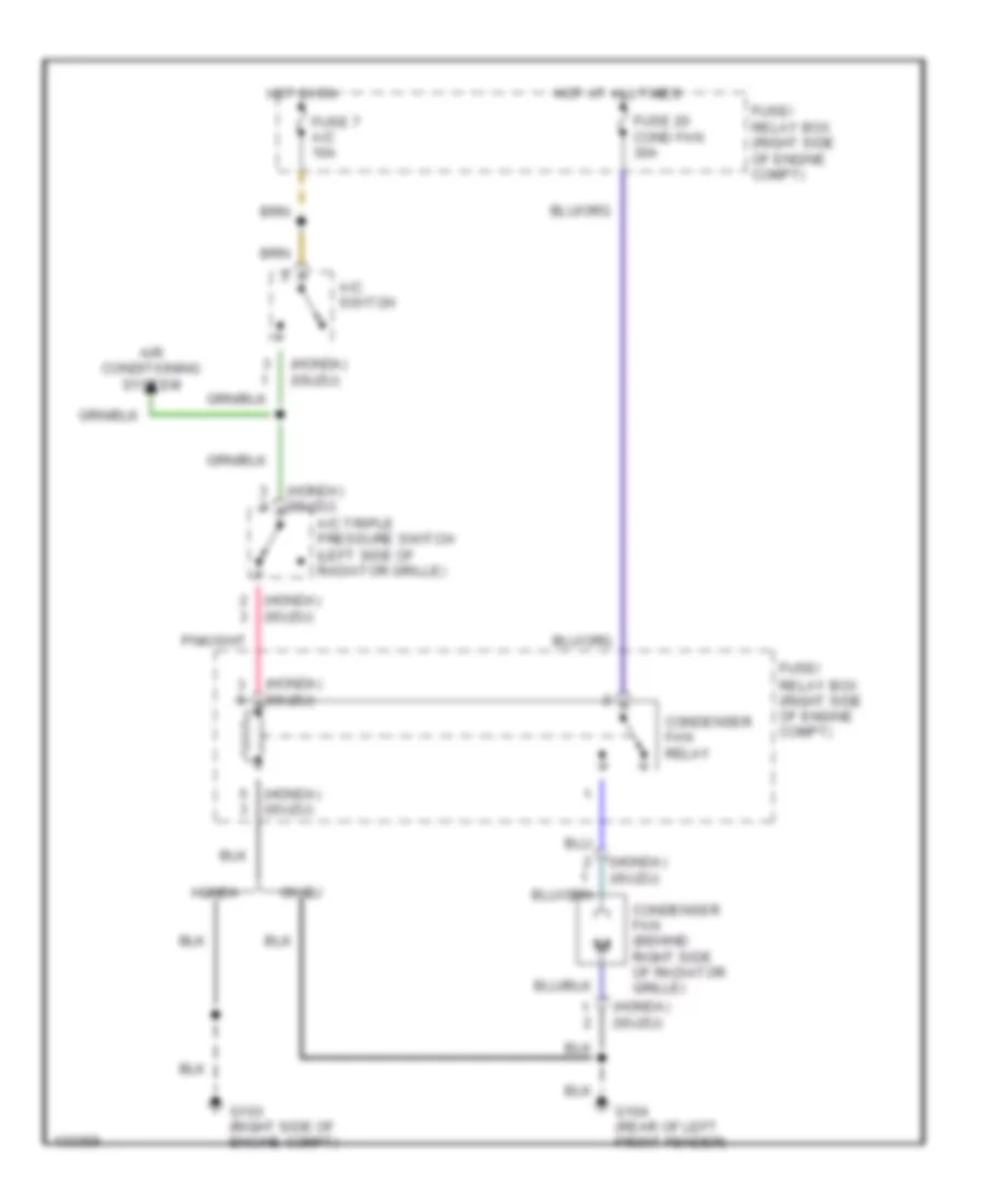
3.2L 3.2L, Cooling Fan Wiring Diagram for Isuzu Rodeo LSE 2001 List of elements for 3.2L, Cooling Fan Wiring Diagram for Isuzu Rodeo LSE 2001: 15 (honda) (isuzu) A/c switch A/c triple pressure switch (left side of radiator grille) Air conditioning system Condenser fan (behind right side of radiator grille) Condenser fan relay Fuse 20 cond fan 30a Fuse 7 a/c 10a Fuse/ relay box (right side of engine compt) G103 (right side of engine compt) G104 (rear of left front fender) Honda Hot at all times Hot in on Isuzu
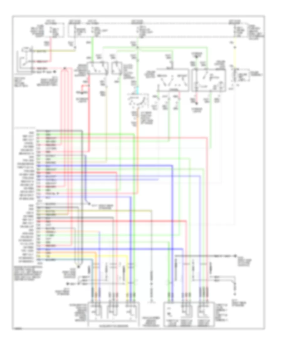
CRUISE CONTROL Cruise Control Wiring Diagram for Isuzu Rodeo LSE 2001 List of elements for Cruise Control Wiring Diagram for Isuzu Rodeo LSE 2001: 63 (right rear of engine) A/t gear position switch (left side of trans) Acceleration position sensor assembly (on accel pedal bracket) Acceleration sensors Ap sen1 gnd Ap sen2 gnd Ap sensor 1 Ap sensor 2 Ap sensor 3 Aps3 gnd Brake sw in Brake switch (on brake pedal support) Cancel Cb-11 meter fuse 15a Cb-14 back-up/ turn light fuse 15a Cb-6 stop light fuse 15a Clutch switch (on clutch pedal support) Cruise brake Cruise control main switch Cruise control res/acc switch Cruise lmp Cruise set light Cruise sw Dash fuse box (behind dash, left of steering column) Drive input E-21 E-22 Eb-17 ecm fuse 30a Engine fuse 12 15a Engine or powertrain control module (2001 3.2l: left rear of engine compartment) (2000, 2001 2.2l: below center of dash) Exterior lights Fuse/ relay box (right side of engine compt) G111 (right side of engine compt behind battery) G117 G117 (right rear of engine) G120 (right side of intake manifold) Gauge assembly Gnd Hot at all times Hot in on or start I-9 Ign feed Illum Interior lights On ind On switch Pcm main relay (in fuse/ relay box) Red Ref volt Res/acc in Set/cst Th val mtr Throttle position sensor 1 Throttle position sensor 2 Throttle val Throttle valve assembly (on throttle body assembly) Throttle valve motor Tps 1 sign Tps1 gnd Tps2 gnd Tps2 sign Vehicle speed sensor (rear of transmission) Vss in
DEFOGGERS Defogger Wiring Diagram for Isuzu Rodeo LSE 2001 List of elements for Defogger Wiring Diagram for Isuzu Rodeo LSE 2001: 32 2.2l 3.2l A14 C-1 C-3 Dash fuse box (behind dash, left of steering column) Defogger Defogger relay control e-22 Defogger request input e-22 E12 Engine control module or powertrain control module (2000, 2001 2.2l: below center of dash, 2001 3.2l: left rear of engine compt) Fuse 10 rear defogger 15a Fuse 16 main 100a Fuse 16 rear wiper 10a Fuse 8 mirror defogger 10a Fuse 9 rear defogger 15a Fuse/relay box (on right side of engine compartment) G302 (below center console) G302 (under center console) Hot at all times Hot in on Interior lights system Left power mirror Mirror defogger switch On indicator Rear window defogger Rear window defogger relay Rear window defogger switch Rear window defogger switch light Right power mirror W/ rear defogger W/o rear defogger
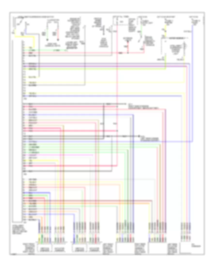
ELECTRONIC SUSPENSION Electronic Suspension Wiring Diagram for Isuzu Rodeo LSE 2001 List of elements for Electronic Suspension Wiring Diagram for Isuzu Rodeo LSE 2001: 35 (lower left side of dash) data link connector 30a Actuator g-sensor Brake switch (beneath center console) C50 C51 C52 Dash and console lights Engine or powertrain control module (2001 3.2l: left rear of engine compartment, 2000, 2001 2.2l: below center of dash) Exterior lights Fuse 11 meter 15a Fuse 15 elec. 15a Fuse 6 stop light 15a G-3 g-sensor G104 (left rear corner of engine compart) G111 (right side of engine compartment, behind battery) G120 (right side of intake manifold) Hot at all times Hot in on Hot in on or start Illumination Intelligent suspension control unit (below center ogf dash) Intelligent suspension mode switch Intelligent suspension warning system light Left front actuator assembly (on top of left front shock) Left rear actuator assembly (on top of left rear shock) Meter assembly Off Option fuse box (right rear of engine compt) Pnk Red Right front actuator assembly (on top of right front shock) Right rear actuator assembly (on top of right rear shock) Vehicle speed sensor (rear of trans) Verticle g-sensor
ENGINE PERFORMANCE
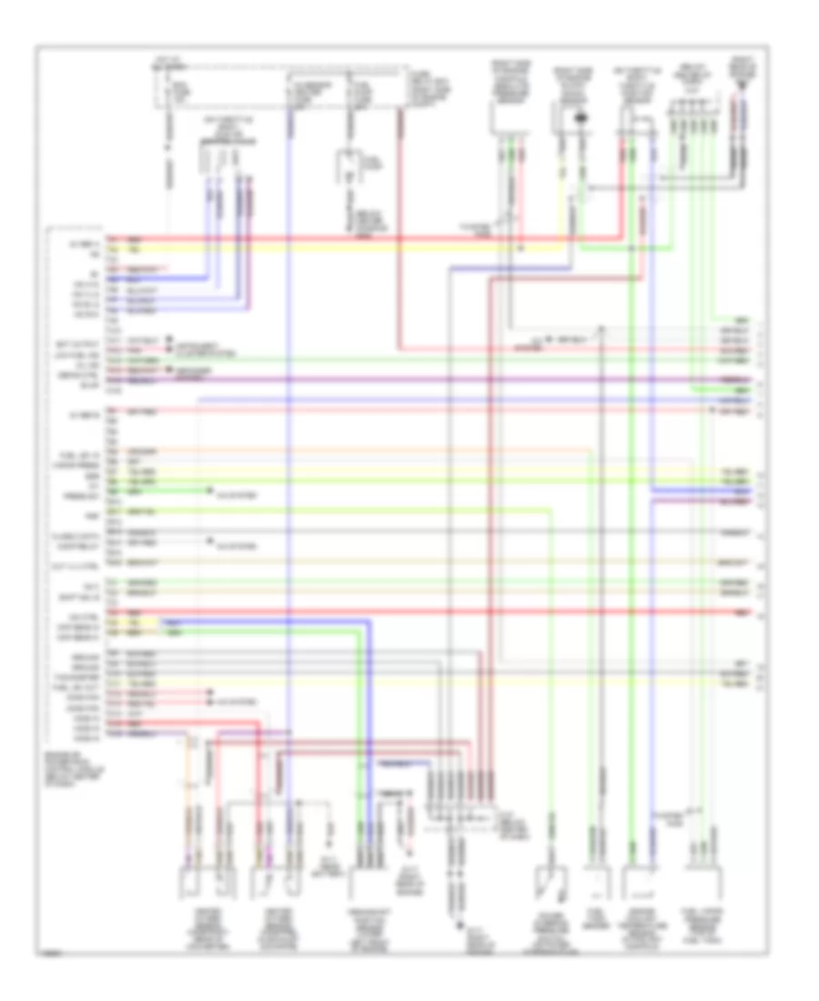
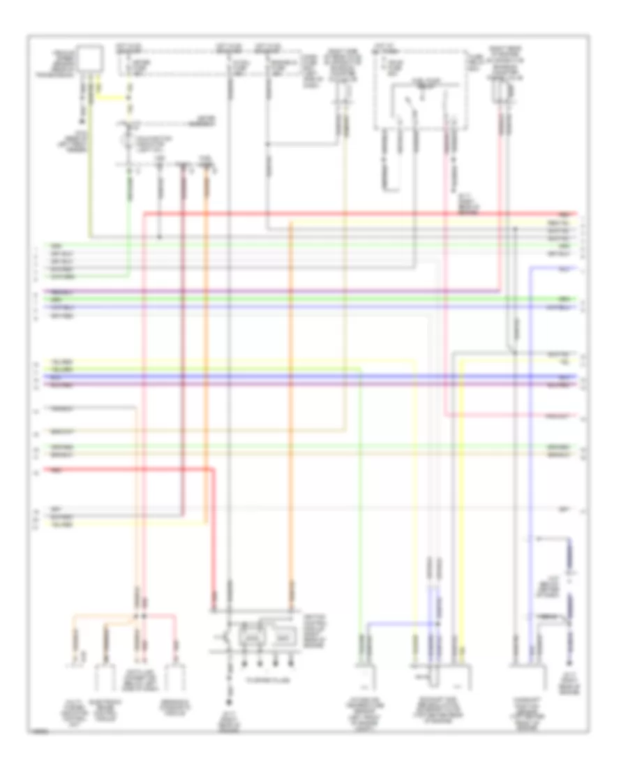
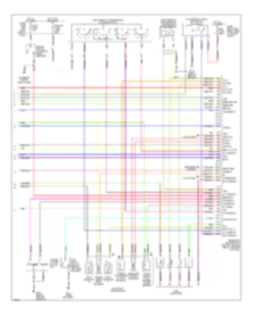
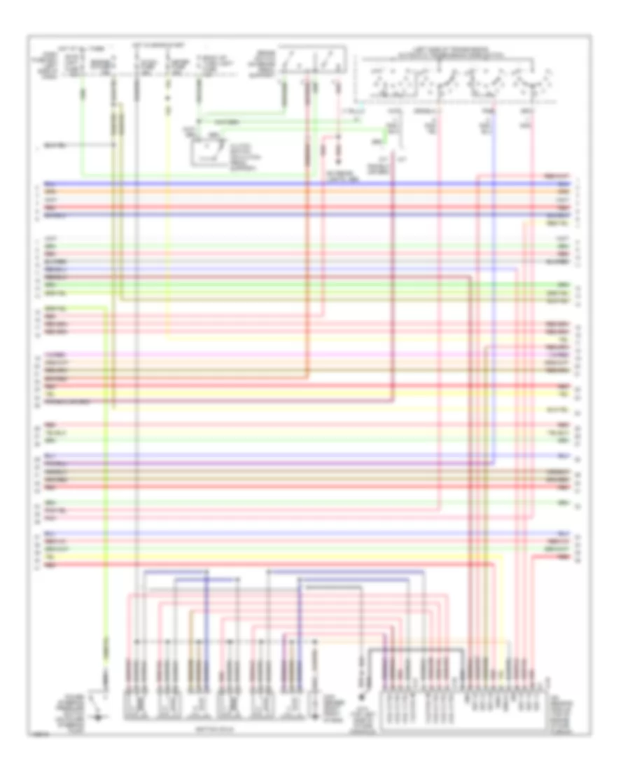
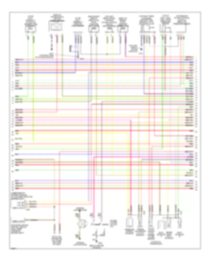
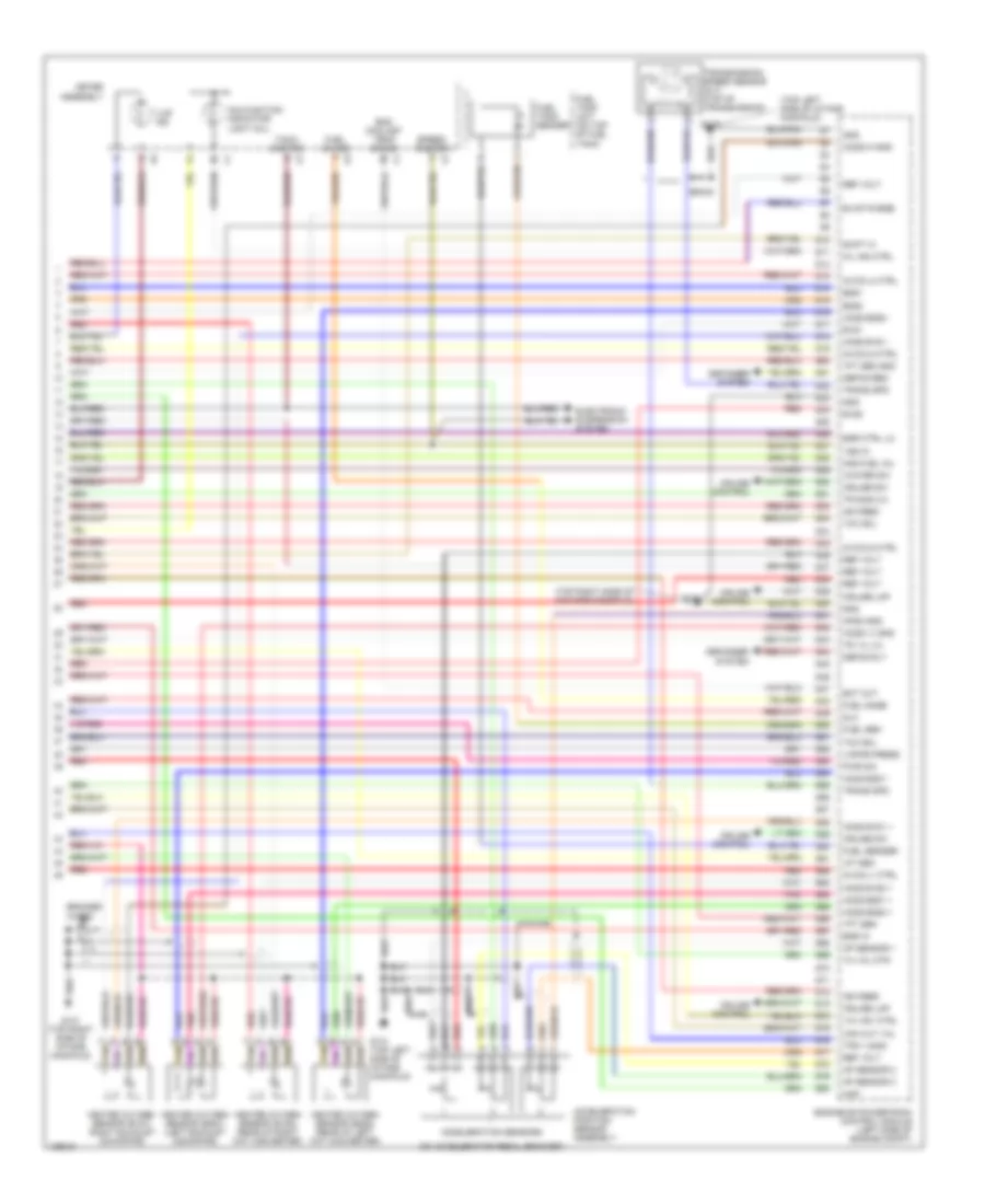
2.2L 2.2L, Engine Performance Wiring Diagrams (1 of 3) for Isuzu Rodeo LSE 2001 List of elements for 2.2L, Engine Performance Wiring Diagrams (1 of 3) for Isuzu Rodeo LSE 2001: 88 (below (on throttle body) (on throttle body) idle air control valve (right rear of engine) g117 (right side of engine block) (right side of engine) 5v ref a 5v ref b A/c system A10 A11 A12 A13 A14 A15 A16 B10 B11 B12 B13 B14 B15 B16 Braid C-37 C-37 (below center of dash) C10 C11 C12 C13 C14 C15 C16 Center console) g302 Center of dash) Ckp sens hi Ckp sens in Class 2 data Comp relay Cond fan Crankshaft position sensor (lower left front of engine) Cut vlv ctrl Defog ctrl Defogger system Ecm fuse 15a Ect output Egr Engine coolant temperature sensor (in coolant manifold) Engine or powertrain control module (below center of dash) Evap Fuel lev in Fuel lev out Fuel pump Fuel pump fuse 20a Fuel tank sender Fuel vapor pressure sensor (top of fuel tank) Fuse/ relay box (right side of engine compt) G111 (near battery) G117 (right rear of engine) Ground Heated oxygen sensor (ho2s-post) (rear of converter) Heated oxygen sensor (ho2s-pre) (in exhaust downpipe) Ho2s in Hot at all times Iac a hi Iac a lo Iac b hi Iac b lo Iat Icm ctrl Inj 2 Instrument cluster system Knock sensor Low fuel ind Manifold absolute pressure sensor Mil ind O2 sensor heater fuse 20a Pnk Power steering pressure switch (on power steering pump) Press sw Psp Red Shift sol b Tachometer Tan Throttle position sensor Twisted pair Vapor press 2.2L, Engine Performance Wiring Diagrams (2 of 3) for Isuzu Rodeo LSE 2001 List of elements for 2.2L, Engine Performance Wiring Diagrams (2 of 3) for Isuzu Rodeo LSE 2001: 37 (right rear of engine) (right side of rear axle) evaporative emission canister cut valve B-26 Braid C-37 (below center of dash) Camshaft position sensor (top center Dash fuse box (left side of dash) Data link connector (below left side of dash) Electronic brake control module Engine ig fuse 15a Evaporative emission canister purge valve Exhaust gas recirculation solenoid valve (top center rear of engine) Front of engine) Fuel level Fuel pump relay Fuse/ relay box G104 (rear of left front fender) G117 (right rear of engine) Hot at all times Hot in on or start I-1 I-2 I-9 Ig coil fuse 15a Ign b1 fuse 60a Ignition control module (right rear of engine) Intake air temperature sensor (left front of engine compt) Malfunction indicator light (mil) Meter assembly Meter fuse 15a Multi- plexed indicator control unit Red Sensing & diagnostic module Tach To spark plugs Vehicle speed sensor (rear of transmission) Vss in 2.2L, Engine Performance Wiring Diagrams (3 of 3) for Isuzu Rodeo LSE 2001 List of elements for 2.2L, Engine Performance Wiring Diagrams (3 of 3) for Isuzu Rodeo LSE 2001: 89 (in fuse/relay box) ecm or pcm main relay (left rear of transmission) transmission speed sensor (left side of transmission) a/t mode switch A/c request A/c system A/t mode sw Automatic transmission Backup/ turn fuse 15a Bba sol Braid Brake sw Brake switch (on brake pedal bracket) Cmp sens in Cond fan D10 D11 D12 D13 D14 D15 D16 Dash fuse box (left side of dash) Defog req Defogger system Duty sol E10 E11 E12 E13 E14 E15 E16 Ecm fuse 15a Ects Egr vlv ctrl Engine or powertrain control module (below center of dash) Exterior lights, abs system F10 F11 F12 F13 F14 F15 F16 Fp relay Fuel injectors Fuse/ relay box (right side of engine compt) G111 (near battery) G117 G117 (right rear of engine) G302 (below center console) Ho2s in Hot at all times Hot in on or start Icm ctrl Ignition Inj 1 Inj 3 Inj 4 Kick down switch (behind left side of dash) Kick dwn sw M-6 M-7 Map Pc sol + Pc sol - Pnk Power Power sw Power/ winter switch (a/t) Pressure control solenoid Red Sens grd Sens return Shift sol a Shift solenoid a Shift solenoid b Stop fuse 15a Switched b+ Tcc sol Tft sens Torque converter clutch solenoid Tps Trans- mission fluid temper- ature sensor Tss + Tss - Vss Winter Winter sw
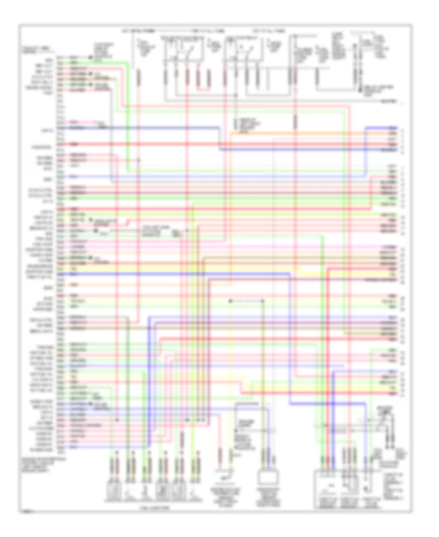
3.2L 3.2L, Engine Performance Wiring Diagrams (2 of 4) for Isuzu Rodeo LSE 2001 List of elements for 3.2L, Engine Performance Wiring Diagrams (2 of 4) for Isuzu Rodeo LSE 2001: 42 (left side of transmission) automatic transmission mode switch 1,3,5 coil in 2,4,6 coil in A/t Back up/ turn light fuse 15a Brake switch (on brake pedal support) Clutch switch (on clutch pedal support) Coil 1 ctrl Coil 2 ctrl Coil 3 ctrl Coil 4 ctrl Coil 5 ctrl Coil 6 ctrl Con- denser (right front of eng) Dash fuse box (left side of dash) E-16 E-17 E-18 Engine ig fuse 15a Est 11 Est 12 Est 13 Est 21 Est 22 Est 23 Exterior lights, abs G131 (top left side of intake manifold) Gnd Hot at all times Hot in on or start Ig coil fuse 15a Ign Ignition coils Ion sensing module (top of engine intake plenum) Ioncq1 Ionk1 M/t Meter fuse 15a Pnk Power steering pressure switch (on power steering pump) Red Stop light fuse 15a 3.2L, Engine Performance Wiring Diagrams (3 of 4) for Isuzu Rodeo LSE 2001 List of elements for 3.2L, Engine Performance Wiring Diagrams (3 of 4) for Isuzu Rodeo LSE 2001: 34 "u/s" ind (above right side of rear axle) evap canister cut valve (below center console) (front of engine) evap canister purge valve (in air duct assembly) intake air temperature sensor (in air duct assembly) mass air flow sensor (rear of transmission) vehicle speed sensor (top left rear of eng) variable intake manifold vacuum switch valve (top left side of intake manifold) (top of fuel tank) fuel vapor pressure sensor (top rear of intake manifold) manifold absolute pressure sensor (top right rear of engine) exhaust gas recirculation solenoid valve (under rear of center console) multiplexed indicator control unit A11 Automatic transmission B-26 Data link connector (on lower left side of dash) E-52 E-54 Electronic brake control module (right rear corner of engine compt) G131 G131 (top right side of intake manifold) G302 Interior lights system Power Power/ winter switch (a/t) Pressure control solenoid Red Serial data Shift solenoid a Shift solenoid b Torque converter clutch solenoid Trans- mission fluid temper- ature sensor Winter
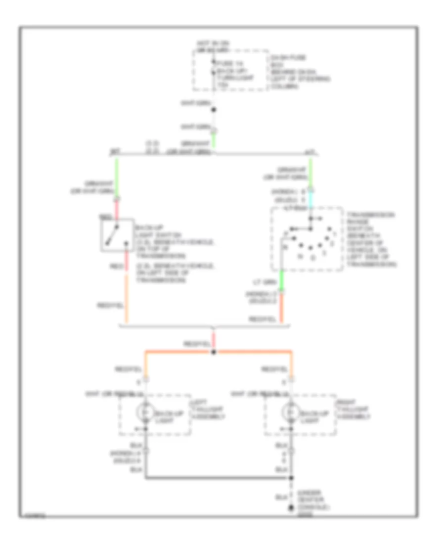
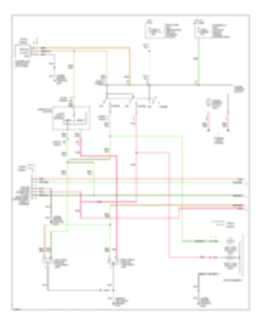
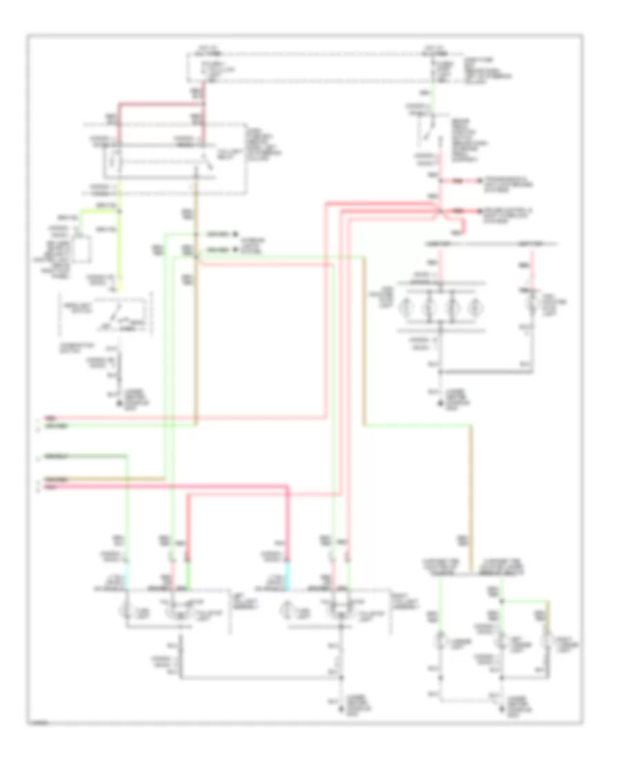
EXTERIOR LIGHTS Back-up Lamps Wiring Diagram for Isuzu Rodeo LSE 2001 List of elements for Back-up Lamps Wiring Diagram for Isuzu Rodeo LSE 2001: 16 (2.2l: beneath vehicle, on left side of transmission) (3.2) (2.2) (honda) (isuzu) (under center console) g302 A/t Back-up light Back-up light switch (3.2l: beneath vehicle, on top of transmission) Dash fuse box (behind dash, left of steering column) Fuse 14 back up/ turn light 15a Hot in on or start Left taillight assembly M/t Red Right taillight assembly Transmission range switch (beneath center of vehicle, on left side of transmission) Exterior Lamps Wiring Diagram (1 of 2) for Isuzu Rodeo LSE 2001 List of elements for Exterior Lamps Wiring Diagram (1 of 2) for Isuzu Rodeo LSE 2001: 36 (honda) (isuzu) (isuzu) (honda) (rear of left front fender) g104 (under center console) g302 B11 B12 B16 Combination switch Dash fuse box (behind dash, left of steering column) Flasher unit (above left kick panel) Fuse 1 hazard 15a Fuse 15 elect ig 15a Fuse/relay box (on right side of engine compartment) Gauge assembly Gnd Hazard Hazard warning switch Hazard warning switch light Hot at all times Hot in on Ignition Interior lights system Left Left front parking/ turn signal light Left turn indicator light Off Output Pnk Rear cargo compartment, taped to harness) Red Right Right front parking/ turn signal light Right turn indicator light Trailer lighting connector (in left Turn signal switch Exterior Lamps Wiring Diagram (2 of 2) for Isuzu Rodeo LSE 2001 List of elements for Exterior Lamps Wiring Diagram (2 of 2) for Isuzu Rodeo LSE 2001: 37 (honda) (honda) (isuzu) (honda) a (isuzu) (under center console) g302 Brake pedal position switch (behind dash, on brake pedal support) Combination switch Cruise control & shift interlock systems Dash fuse box (behind dash, left of steering column) Fuse 4 tail/illumi light 15a Fuse 6 stop light 15a Hard-top Head Headlight switch High mounted stop light Hot at all times Interior lights system Keyless entry & security control unit (above right kick panel) Left license light Left taillight assembly License light Off Park Pnk Red Red red Right license light Right taillight assembly Soft-top Stop Tail Tail/stop light Taillight relay Transmission & anti-lock brakes systems Turn light W/spare tire mounted on tailgate W/spare tire mounted under rear of vehicle
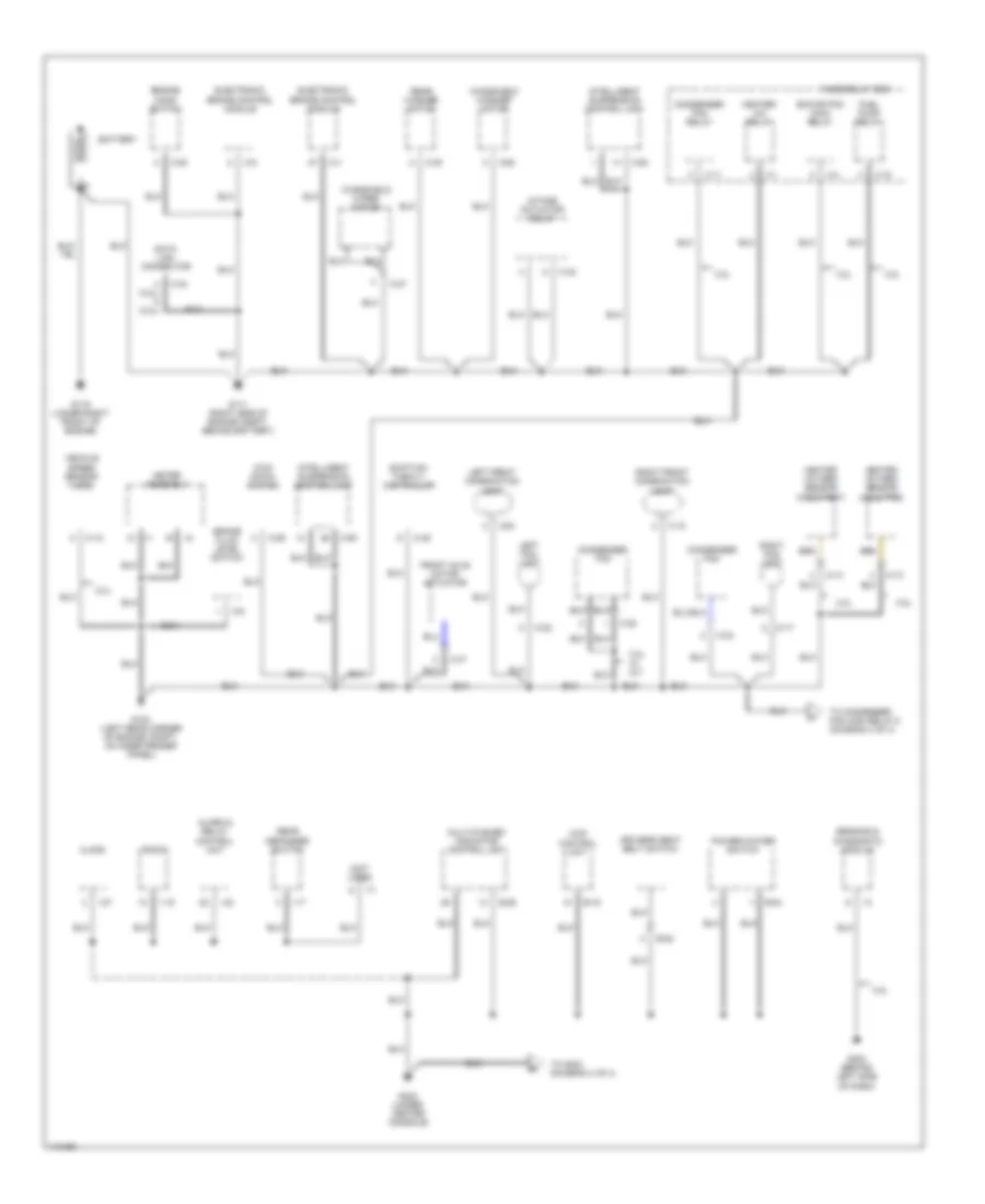
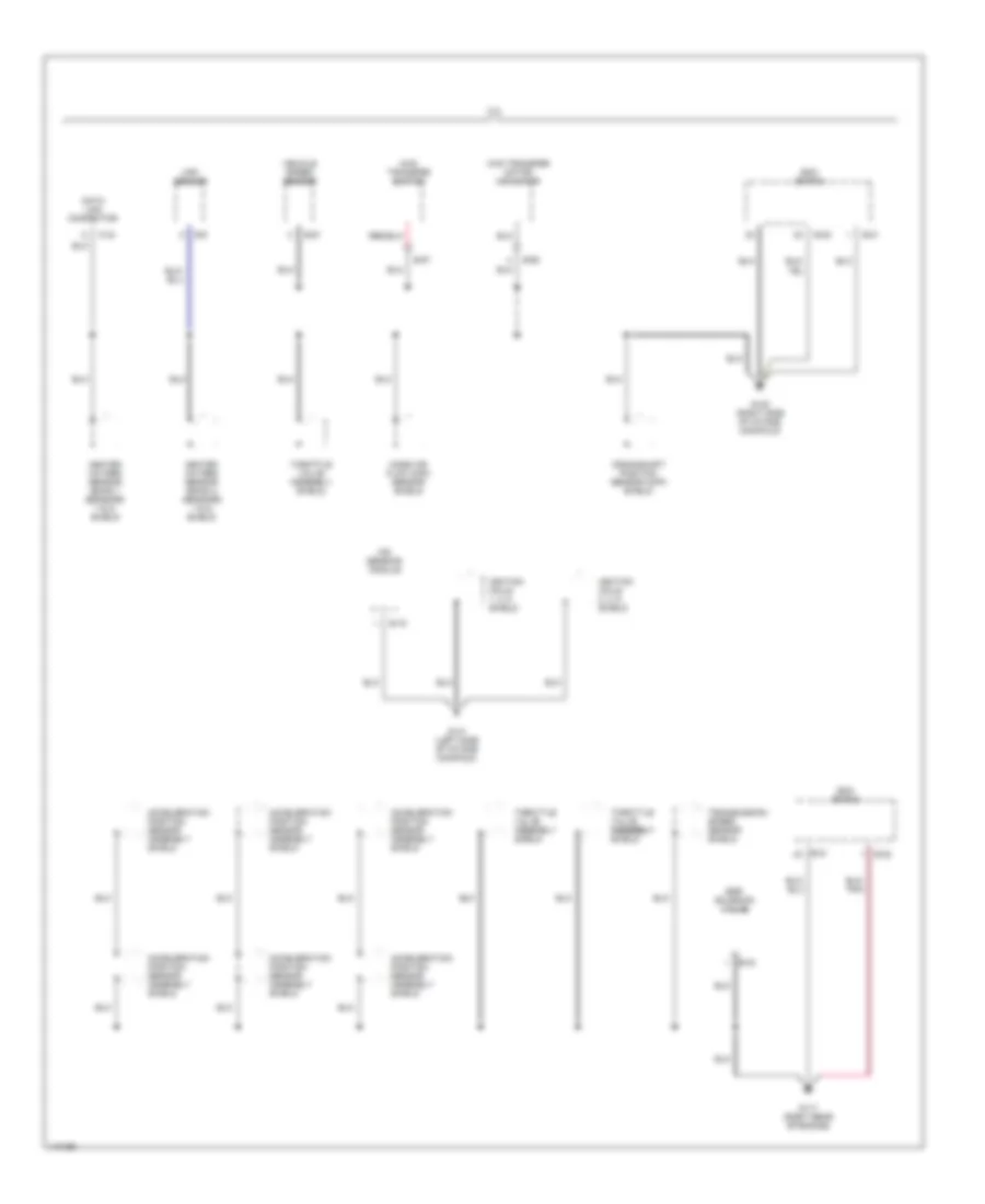
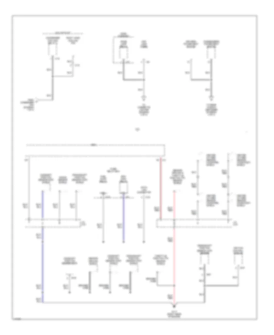
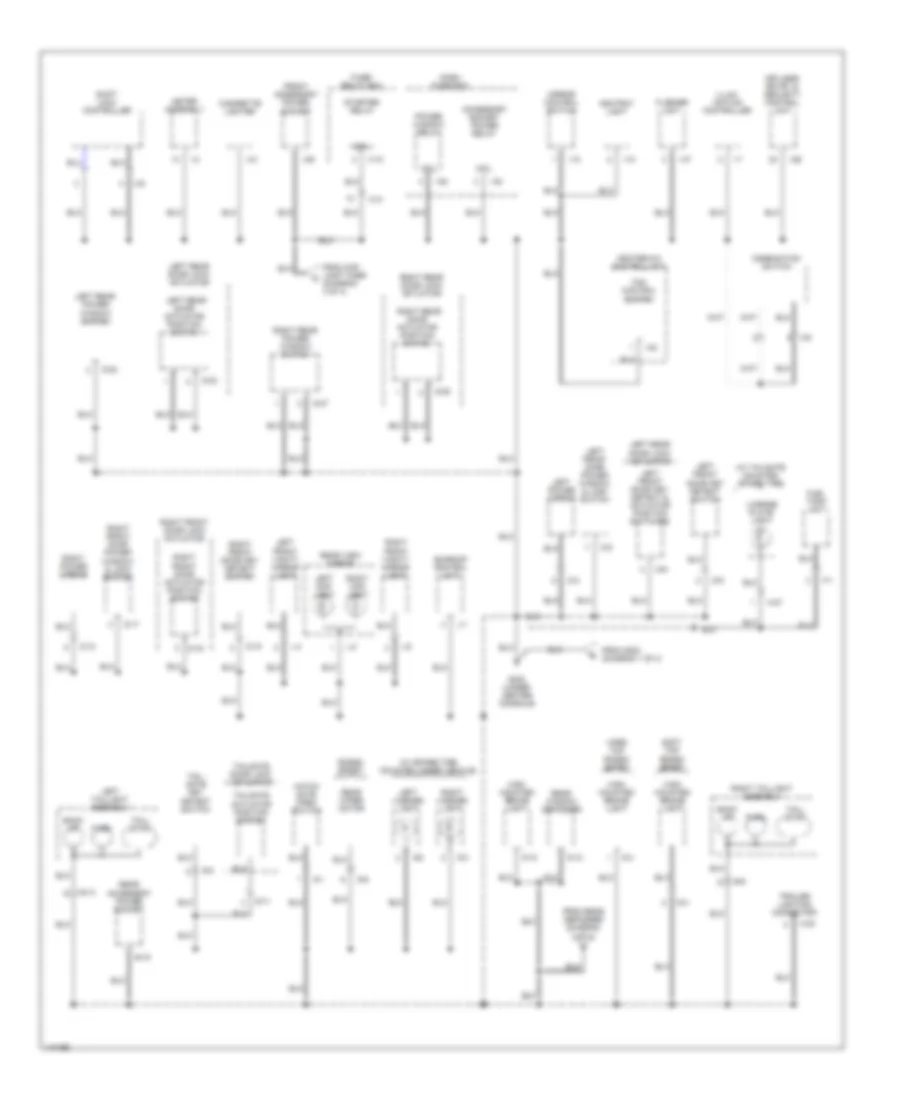
GROUND DISTRIBUTION Ground Distribution Wiring Diagram (1 of 4) for Isuzu Rodeo LSE 2001 List of elements for Ground Distribution Wiring Diagram (1 of 4) for Isuzu Rodeo LSE 2001: 85 (3.2l) (2.2l) (not used) 1-15 2.2l 2.2l w/ m/t 3.2l 4wd control unit Alarm & relay control unit B-19 B-22 B-24 B-26 Battery Brake fluid level switch C-17 C-18 C-20 C-22 C-23 C-24 C-27 C-28 C-29 C-30 C-34 C-35 C-4 C-42 C-47 C-49 C-5 C-50 C-6 Clock Condenser fan Condenser fan relay Data link connector Driver's seat belt switch Ecm or pcm main relay Electronic brake control module Engine hood switch Front axle motor actuator Fuel pump relay Fuse/relay box G104 (left rear corner of engine compt, on inner fender panel) G111 (right side of engine compt, behind battery) G119 (lower right front of engine) G202 (behind left side of dash) G302 (under center console) Heated oxygen sensor (ho2s-post) Heated oxygen sensor (ho2s-pre) Heater- a/c relay I-1 I-17 I-2 I-27 I-3 I-42 Intake actuator relay Intelligent suspension control unit Kick down switch Left fog light Left front combination light M-10 M-13 M-14 Meter assembly Multi-plexed indicator control unit Power/winter switch Radio Rear defogger switch Rear washer motor Right fog light Right front combination light Sensing & diagnostic module Shift-on- the-fly controller To condenser fan high relay 2 (diagram 3 of 4) To g302 (diagram 4 of 4) Vehicle speed sensor (vss) Windshield washer motor Windshield wiper motor X-1 X-11 X-12 X-4 Ground Distribution Wiring Diagram (2 of 4) for Isuzu Rodeo LSE 2001 List of elements for Ground Distribution Wiring Diagram (2 of 4) for Isuzu Rodeo LSE 2001: 31 3.2l 4wd transfer motor actuator 4wd transfer switch Acceleration position sensor assembly shield C-34 Crankshaft position sensor (ckp) shield Data link connector E-16 E-21 E-22 E-33 E-57 E-6 E-60 E-61 Ecm or pcm Egr solenoid valve G117 (right rear of engine) G120 (right side of intake manifold) G131 (left side of intake manifold) Heated oxygen sensor (bank 1 sensors 1 & 2) shield Heated oxygen sensor (bank 2 sensors 1 & 2) shield Ignition coils 1, 3, 5 shield Ignition coils 2, 4, 6 shield Ion sensing module Maf sensor Mass air flow (maf) sensor shield Throttle valve assembly assembly shield Throttle valve assembly shield Transmission speed sensor shield Vehicle speed sensor Ground Distribution Wiring Diagram (3 of 4) for Isuzu Rodeo LSE 2001 List of elements for Ground Distribution Wiring Diagram (3 of 4) for Isuzu Rodeo LSE 2001: 43 2.2l 2.2l with a/t Braided wire C-2 C-34 C-72 Camshaft position sensor (cmp) Camshaft position sensor (cmp) shield Coil Condenser fan high relay 2 Crankshaft position sensor (ckp) sensor Crankshaft position sensor (ckp) shield Dash fuse box Data link connector Dome lamp relay Driver's power seat switch E-27 E-32 E-37 Ecm Ecm main relay From a condenser fan (diagram 1 of 4) Fuel pump relay Fuse/ relay box G117 (right rear of engine) Heated oxygen sensor (ho2s-post) shield Heated oxygen sensor (ho2s-pre) shield I-37 I-54 Ignition control module J/c c-37 Knock sensor shield Map lamp timer Passenger's power seat switch Right hand cooling fan Sensor ground & throttle position (tp) sensor shield Sensor ground shield Throttle position (tp) sensor shield To cigarette lighter (diagram 4 of 4) To rear window defogger (diagram 4 of 4) X-12 X-15 X-4
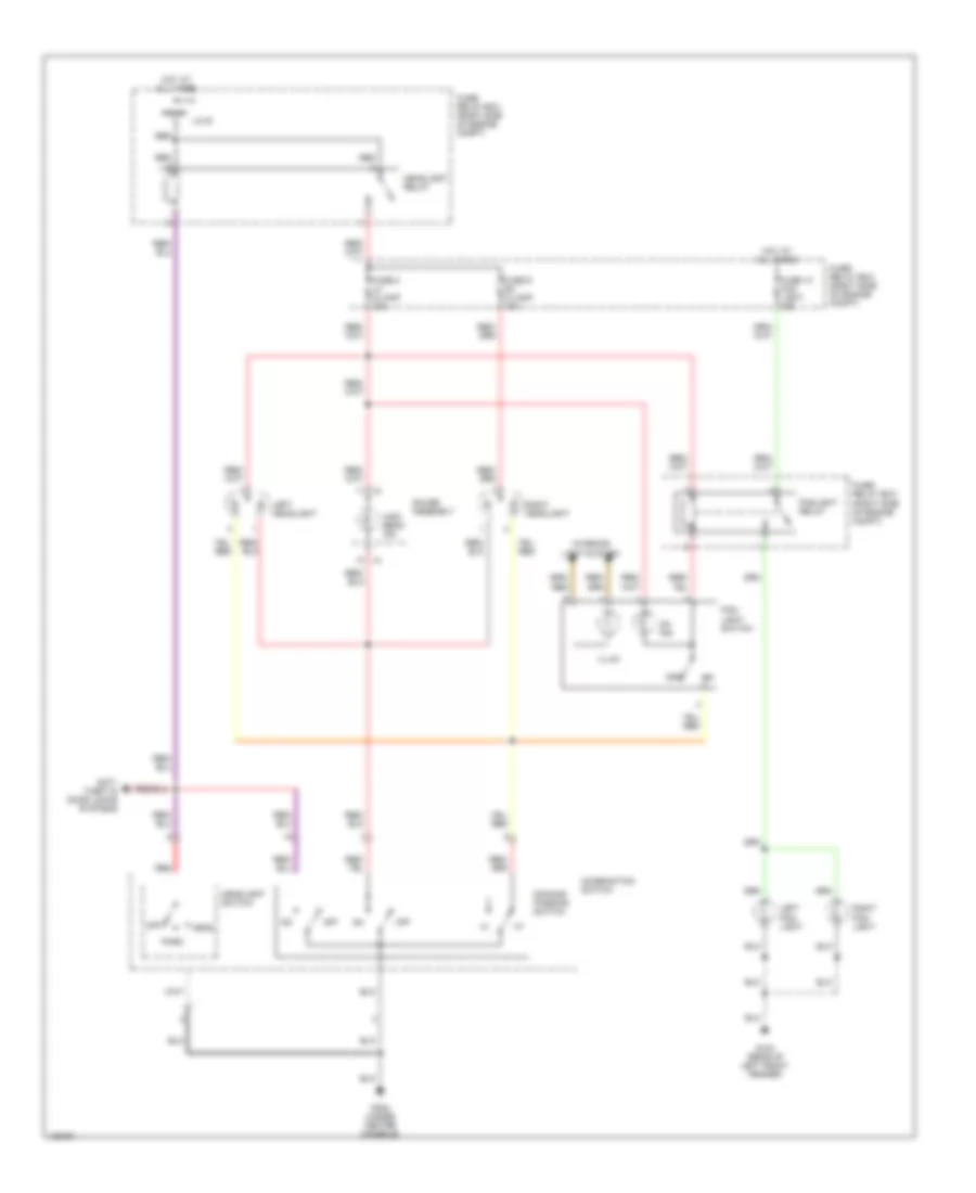
HEADLIGHTS Headlight Wiring Diagram for Isuzu Rodeo LSE 2001 List of elements for Headlight Wiring Diagram for Isuzu Rodeo LSE 2001: 29 Anti- theft & door locks systems Combination switch Dimming/ passing switch Fog- light switch Foglight relay Fuse 10 fog light 15a Fuse 8 lh h/lamp 10a Fuse 9 rh h/lamp 10a Fuse/ relay box (right side of engine compt) G104 (rear of left front fender) G302 (under center console) Gauge assembly Head Headlight relay Headlight switch High beam ind Hot at all times I-2 Illum Interior light system J/c b Left fog- light Left headlight Off On ind Park Red Right fog- light Right headlight
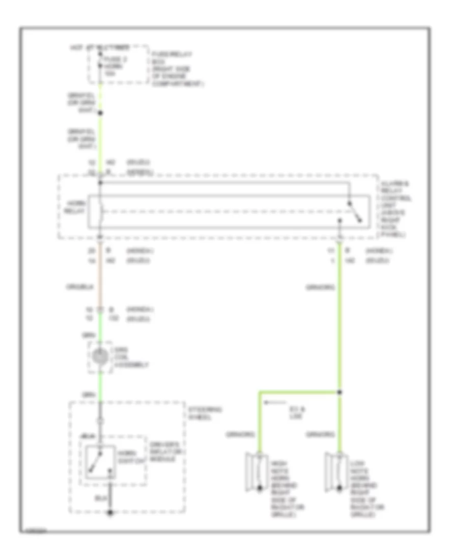
HORN Horn Wiring Diagram for Isuzu Rodeo LSE 2001 List of elements for Horn Wiring Diagram for Isuzu Rodeo LSE 2001: 16 (honda) (isuzu) Alarm & relay control unit (above right kick panel) Driver's inflator module Ex & lse Fuse 2 horn 10a Fuse/relay box (right side of engine compartment) High note horn (behind right side of radiator grille) Horn relay Horn switch Hot at all times I32 I42 Low note horn (behind right side of radiator grille) Srs coil assembly Steering wheel
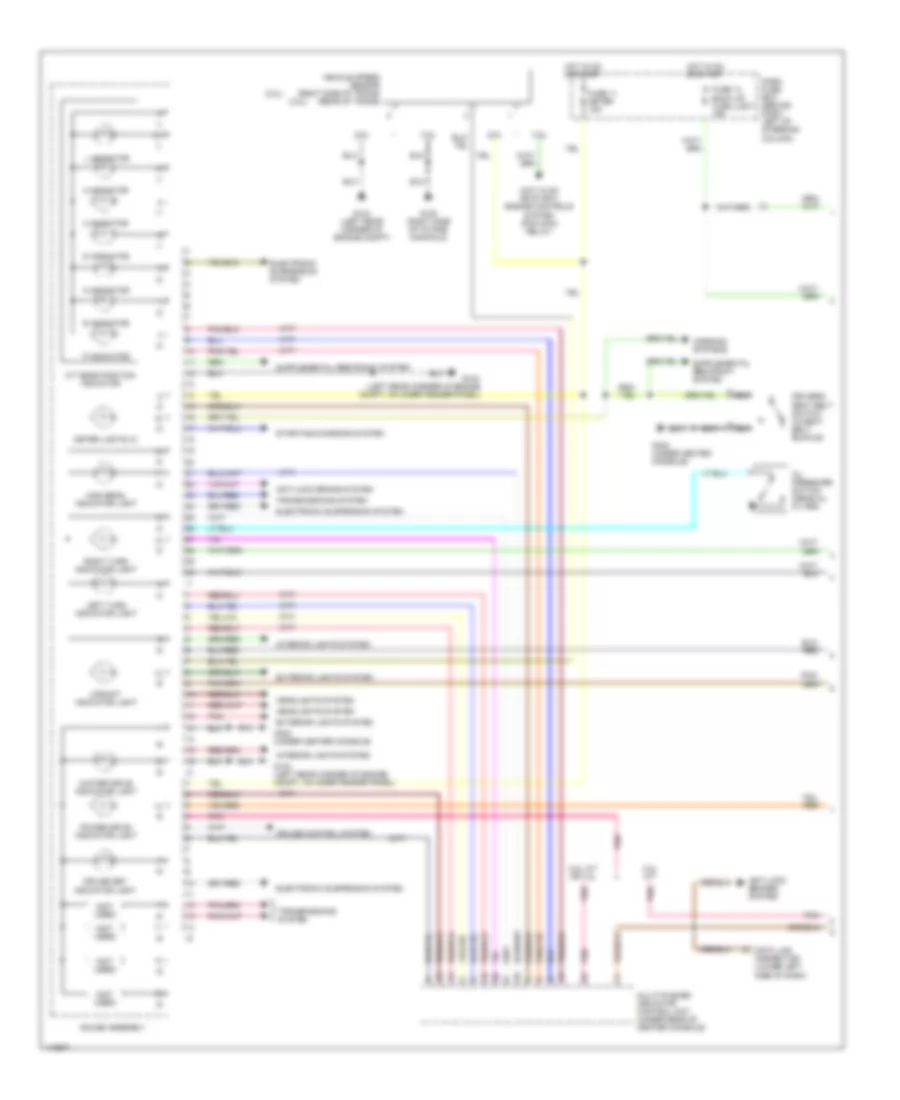
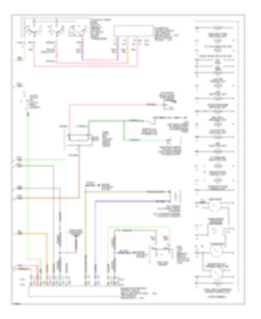
INSTRUMENT CLUSTER Instrument Cluster Wiring Diagram (1 of 2) for Isuzu Rodeo LSE 2001 List of elements for Instrument Cluster Wiring Diagram (1 of 2) for Isuzu Rodeo LSE 2001: 51 (2.2l) (3.2l) (a/t) (hot in on or start) engine controls system (pcm main relay) (m/t) (not used) 2 indicator 2.2l 2.2l a/t or 3.2l 2.2l m/t 3 indicator 3.2l A/t gear position indicator Anti-lock brake system Anti-lock brakes system Cruise control system Cruise set indicator light D indicator Dash fuse box (behind dash, left of steering column) Data link connector (lower left side of dash) Driver's seat belt switch (in seat belt buckle) Electronic suspension system Exterior lights system Fuse 11 meter 15a Fuse 14 back up/ turn light 15a G104 (left rear corner of engine compt) G104 (left rear corner of engine compt, on inner fender panel) G120 (right side of intake manifold) G302 (under center console) Gauge assembly Headlights system High beam indicator light Hot in on or start Interior lights system L indicator Left turn indicator light Meter lights (4) Muliti-plexed indicator control unit (under rear of center console) N indicator Oil pressure switch (near oil filter) P indicator Pnk Power drive indicator light R indicator Right turn indicator light Starting/charging system Transmissions system Upshift indicator light Vehicle speed sensor (right side of trans) (rear of trans) Warning systems Winter drive indicator light Instrument Cluster Wiring Diagram (2 of 2) for Isuzu Rodeo LSE 2001 List of elements for Instrument Cluster Wiring Diagram (2 of 2) for Isuzu Rodeo LSE 2001: 49 (2.2l) (2.2l) c2 (2.2l: on rear of engine, in coolant mainfold) (3.2l) (3.2l) e22 (not used) (on parking brake lever) 10.1 ohms 4wd indicator light A/t fluid indicator light A11 A12 Abs indicator light Air bag readiness indicator light Automatic trans mode switch (beneath center of vehicle, on left side of transmission) B13 Brake fluid level switch (in reservoir) Brake system warning light C11 Charging system warning light Check trans indicator light Clutch switch (on clutch pedal support) Diode box b E21 E22 Ect sensor (3.2l: on right front of engine) Electronic brake control module (right rear corner of engine compt) Electronic suspension system Engine controls system Engine coolant temperature gauge Engine or powertrain control module (below center of dash) (left rear of engine compt) F15 Fuel gauge Fuel tank sender Fuel tank unit (beneath rear of vehicle, in top of fuel tank) Fuse/ relay box (on right side of engine compt) G104 (left rear corner of engine compt, on inner fender panel) Gauge assembly Intelligent suspension system warning light Low fuel warning light Malfunction indicator light Oil pressure indicator light Park brake switch Pnk Powertrain control module (left rear of engine compt) (below center of dash) Reduced power indicator light Seat belt reminder light Speedometer/ odometer/ trip meter Tachometer
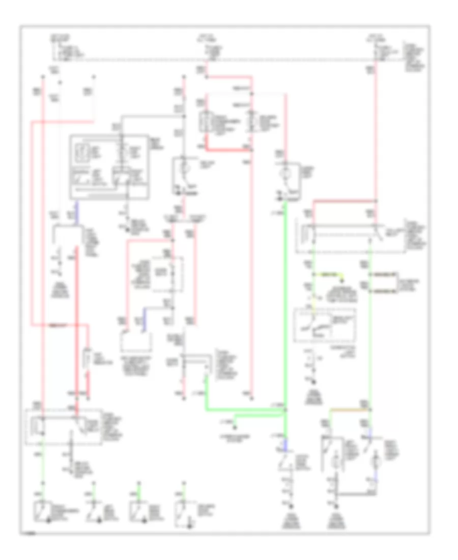
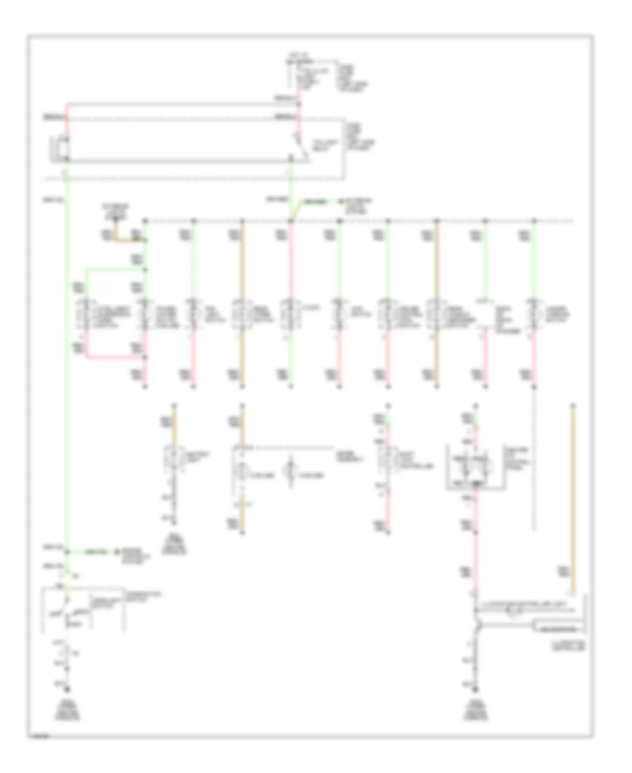
INTERIOR LIGHTS Courtesy Lamps Wiring Diagram for Isuzu Rodeo LSE 2001 List of elements for Courtesy Lamps Wiring Diagram for Isuzu Rodeo LSE 2001: 44 (below center console) g302 Cargo area light Ceiling light Combination light swtich Dash fuse box (behind dash, left of steering column) Diode box 5 Diode box 6 Dome light relay Door Driver's door courtesy light Driver's door switch Exterior lights system Exterior lights, engine controls, anti- theft systems Front passenger's door courtesy light Front passenger's door switch Fuse 14 back up/ turn light 15a Fuse 4 tail/illum light 15a Fuse 5 dome light 10a G302 (under center console) Hatch gate open switch Head Headlight switch Hot at all times Hot in on or start I32 Keyless entry & security control unit (above right kick panel) Left front vanity mirror light Left map light Left map light switch Left rear door switch Map light resistor Map light timer (upper right kick panel) Off Park Rear view mirror Red Right front vanity mirror light Right map light Right map light switch Right rear door switch Taillight relay W/ anti- theft W/o anti- theft Wiper/washer system Instrument Illumination Wiring Diagram for Isuzu Rodeo LSE 2001 List of elements for Instrument Illumination Wiring Diagram for Isuzu Rodeo LSE 2001: 34 (2 bulbs) 4wd switch Ashtray light Center console) Clock Combination swtich Cruise control main switch Dash fuse box (left side of dash) Engine controls system Exterior lights system Fog light switch G302 (under Hazard warning switch Head Headlight switch Heater- a/c control panel Hot at all times I-2 I32 Illumination controller Illumination controller light Intelligent suspension mode switch Meter assembly Off Park Power/ winter switch (2 bulbs) Radio or radio/ cd changer Rear window defogger switch Rear wiper switch Red Shift lock controller Solid state Tail/illum light fuse 4 15a Taillight relay
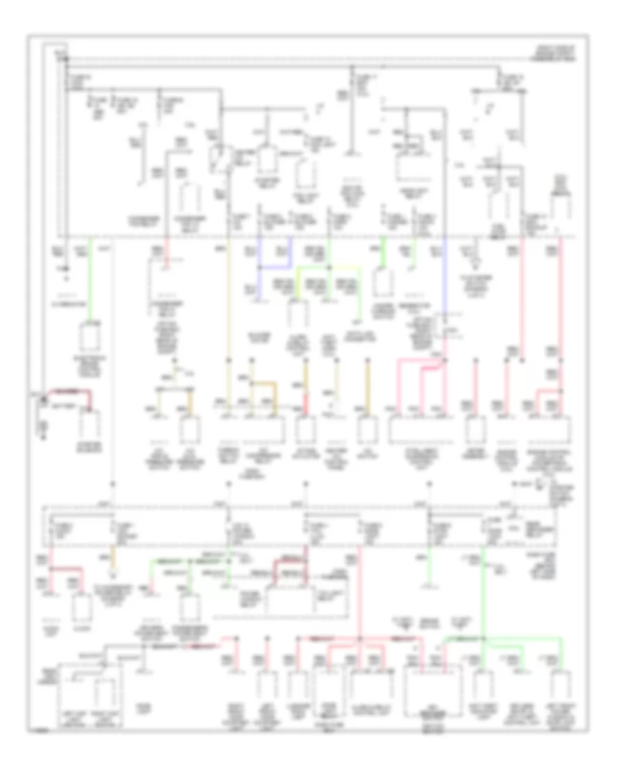
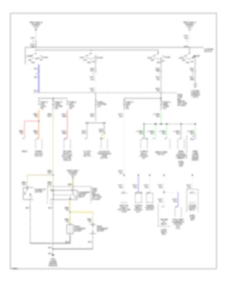
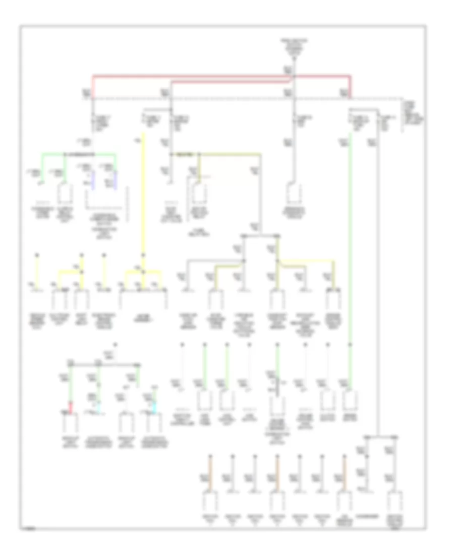
POWER DISTRIBUTION Power Distribution Wiring Diagram (1 of 3) for Isuzu Rodeo LSE 2001 List of elements for Power Distribution Wiring Diagram (1 of 3) for Isuzu Rodeo LSE 2001: 97 (2.2l) ecm main relay (right side of engine compt) fuse/relay box 2.2l 3.2l 3.2l only 30a A/c compressor relay A/c dual pressure switch A/c switch A/c triple pressure switch A/t Alarm & relay control unit Alternator Anti- theft horn (3.2l) Anti-theft indicator light Audio unit Battery Blower motor Brake switch C-5 C.b. 21 power window 30a Clock Coil Condenser fan hi relay Condenser fan lo relay Condenser fan relay Dash fuse box Dash fuse box (behind left side of dash) Data link connector Dome light Dome light relay Driver's power seat switch Ecm or pcm main relay (3.2l) Electronic brake control module Engine control module (2.2l) Engine control module or powertrain control module (3.2l) Fog light relay Fuel pump relay Fuse 1 acc socket 20a Fuse 1 hazard 15a Fuse 10 fog light 15a Fuse 13 ecm, backup 15a Fuse 15 ign, b1 60a Fuse 16 main 100a Fuse 17 ecm 30a (3.2l) Fuse 19 ign. b2 50a Fuse 2 audio 15a Fuse 2 horn 10a Fuse 20 fan 30a Fuse 3 acg-s 10a (3.2l) Fuse 4 tail/ illum 15a Fuse 5 blower 15a Fuse 5 dome light 10a Fuse 6 blower 15a Fuse 6 stop light 15a Fuse 7 a/c 10a Fuse abs 50a Fuse door lock 20a Generator (3.2l) Hazard warning switch Headlight relay Heater- a/c control panel Heater- a/c relay I-41 I-42 Ignition switch Intake actuator Intelligent suspension control unit J/c a J/c b Key reminder switch Keyless entry & anti-theft control unit Left front door courtesy light Left front power window & door lock switch Left map light switch Luggage room light M/t Meter assembly Option fuse box (right rear of engine compt) P-2 P-4 P-9 Passenger's power seat switch Pnk Power window relay Rear defogger relay Rear view mirror Red Right front door courtesy light Right map light switch Starter relay Starter solenoid Taillight relay Thermo- switch relay To accessory power relay (diagram 2 of 3) To starter switch (diagram 2 of 3) W/ anti- theft Power Distribution Wiring Diagram (2 of 3) for Isuzu Rodeo LSE 2001 List of elements for Power Distribution Wiring Diagram (2 of 3) for Isuzu Rodeo LSE 2001: 40 A/t Acc Accessory socket relay Alarm & relay control unit Automatic transmission mode switch Cigarette lighter Clutch start switch Dash fuse box Dash fuse box (behind left side of dash) From fuse 1 (diagram 1 of 3) From fuse 15 (diagram 1 of 3) From fuse 19 (diagram 1 of 3) Front accessory socket Fuse 15 elec ign 15a Fuse 16 rear wiper 10a Fuse 18 acc. audio 10a Fuse 19 cigar lighter 15a Fuse 20 anti- theft 10a Fuse 3 starter 10a Fuse/ relay box G302 (under center console) Hazard warning switch Heater a/c relay I-41 Intelligent suspension control unit (3.2l) Keyless entry & anti-theft control module Lock M/t Mirror control switch Off Power window relay Radio Rear accessory socket Rear window defogger relay Rear wiper motor (rodeo sport) Rear wiper switch Shift-on- the-fly controller (4wd) Start Starter switch To dash fuse box (diagram 3 of 3) Power Distribution Wiring Diagram (3 of 3) for Isuzu Rodeo LSE 2001 List of elements for Power Distribution Wiring Diagram (3 of 3) for Isuzu Rodeo LSE 2001: 54 2.2l 3.2l 3.2l a/t 3.2l m/t 4wd control unit 4wd switch A/t A1 c4 Alarm & relay control unit Automatic transmission mode switch B-26 Back-up light switch Brake switch Camshaft position (cmp) sensor Clutch switch Combination light switch Condenser Cruise control main switch Cruise control switch Dash fuse box (behind left side of dash) E5 c3 Ecm or pcm main relay Electronic brake control module Engine control module (ecm) Evap canister purge valve Evap vent canister cut valve Exhaust gas recirculation (egr) solenoid valve From ignition switch (diagram 2 of 3) Fuse 11 meter 15a Fuse 12 engine ign 15a Fuse 13 ign coil 15a Fuse 14 backup/ turn 15a Fuse 17 front wiper 20a Fuse 22 srs 10a Fuse/ relay box I-1 I-31 I-9 Ignition coil Ignition control module (icm) Ion sensing module M/t Map lamp timer Mass air flow (maf) sensor Meter assembly Multiplex control unit Red Sensing & diagnostic module Shift lock relay Shift-on- the-fly controller Variable air induction vacuum switching valve Vehicle speed sensor (2.2l) Windshield wiper motor Windshield wiper/washer switch
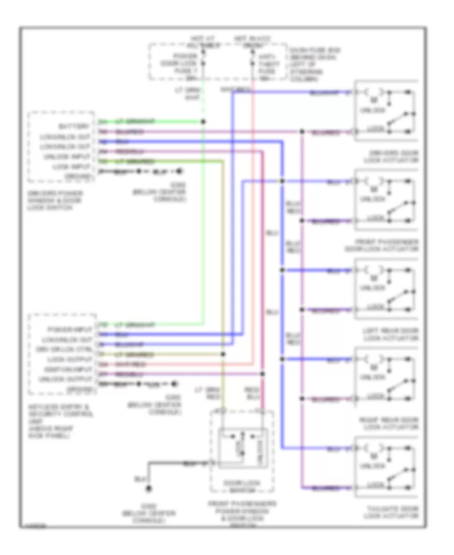
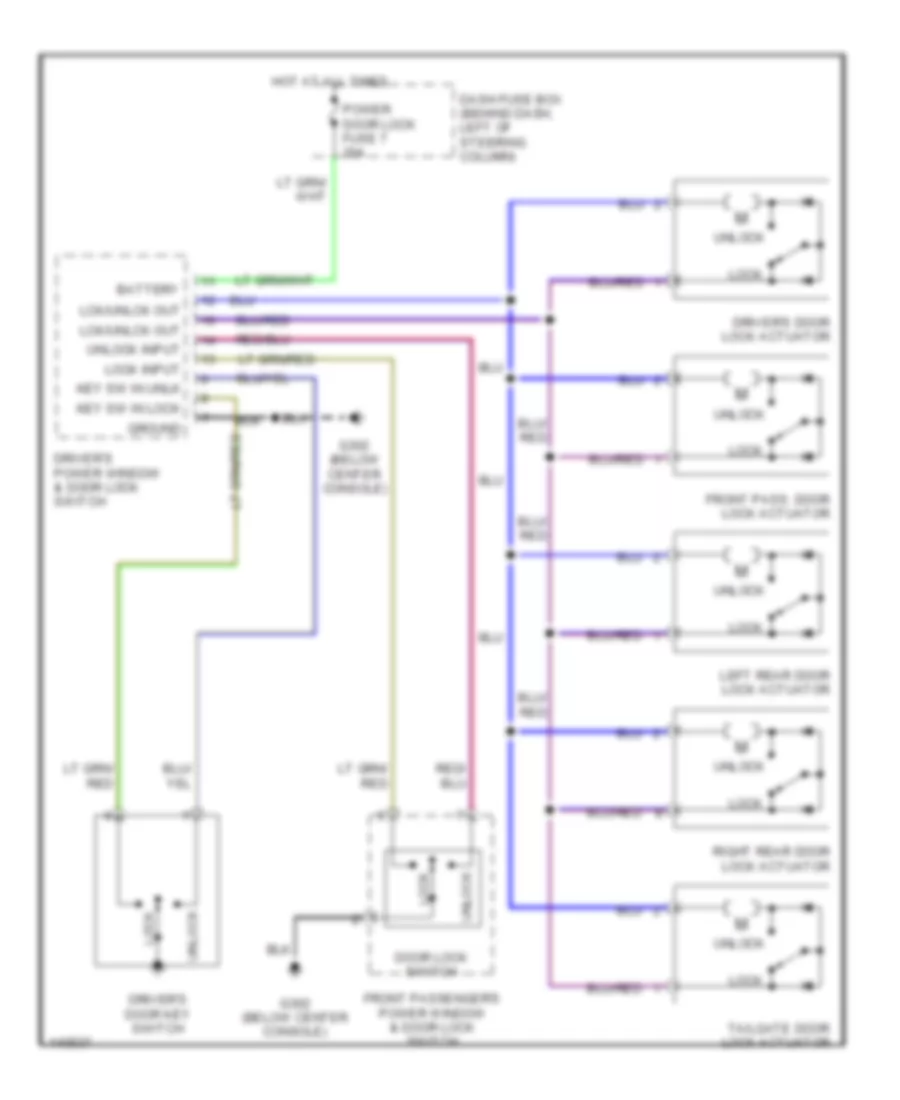
POWER DOOR LOCKS Power Door Lock Wiring Diagram, with Keyless Entry for Isuzu Rodeo LSE 2001 List of elements for Power Door Lock Wiring Diagram, with Keyless Entry for Isuzu Rodeo LSE 2001: 27 Anti- theft fuse 10a Battery Dash fuse box (behind dash, left of steering column) Door lock switch Driver's door lock actuator Driver's power window & door lock switch Drv dr lck ctrl Front passenger door lock actuator Front passenger's power window & door lock switch G302 (below center console) Ground Hot at all times Hot in acc or on Ignition input Keyless entry & security control unit (above right kick panel) Lck/unlck out Left rear door lock actuator Lock Lock input Lock output Power door lock fuse 7 20a Power input Right rear door lock actuator Tailgate door lock actuator Unlock Unlock input Unlock output Power Door Lock Wiring Diagram, without Keyless Entry for Isuzu Rodeo LSE 2001 List of elements for Power Door Lock Wiring Diagram, without Keyless Entry for Isuzu Rodeo LSE 2001: 22 Battery Dash fuse box (behind dash, left of steering column) Door lock switch Driver's door key switch Driver's door lock actuator Driver's power window & door lock switch Front pass. door lock actuator Front passenger's power window & door lock switch G302 (below center console) Ground Hot at all times Key sw in lock Key sw in unlk Lck/unlck out Left rear door lock actuator Lock Lock input Power door lock fuse 7 20a Right rear door lock actuator Tailgate door lock actuator Unlock Unlock input
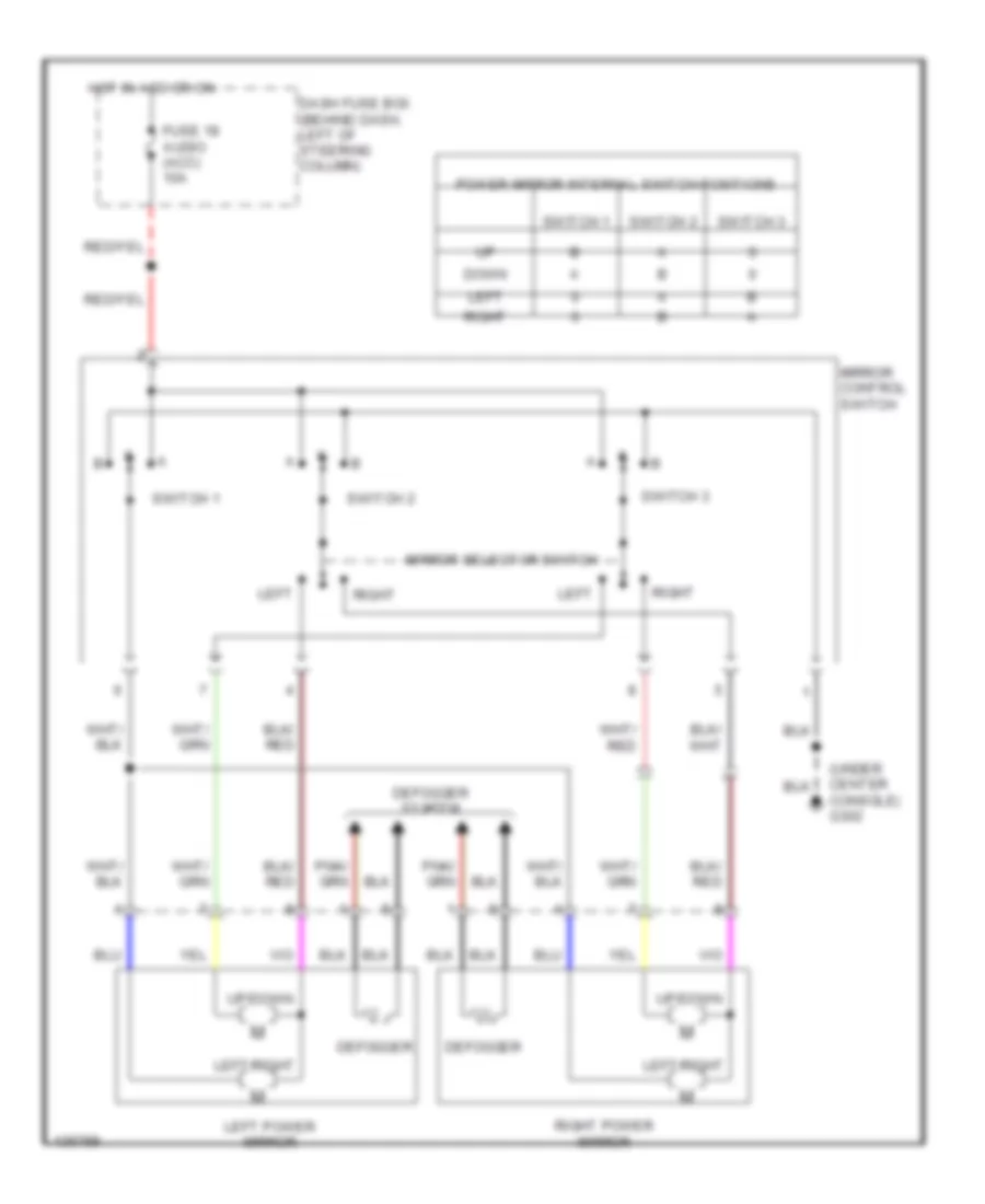
POWER MIRRORS Power Mirror Wiring Diagram for Isuzu Rodeo LSE 2001 List of elements for Power Mirror Wiring Diagram for Isuzu Rodeo LSE 2001: 19 (under center console) g302 Dash fuse box (behind dash, left of steering column) Defogger Defogger system Down Fuse 18 audio (acc) 10a Hot in acc or on Left Left power mirror Left/right Mirror control switch Mirror selector switch Power mirror internal switch positions Right Right power mirror Switch 1 Switch 2 Switch 3 Up/down
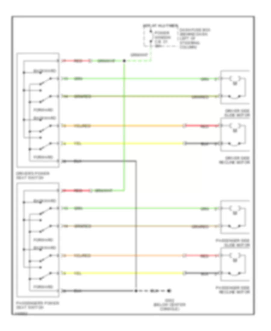
POWER SEATS Power Seat Wiring Diagrams for Isuzu Rodeo LSE 2001 List of elements for Power Seat Wiring Diagrams for Isuzu Rodeo LSE 2001: 13 Backward Dash fuse box (behind dash, left of steering column) Driver side recline motor Driver side slide motor Driver's power seat switch Forward G302 (below center console) Hot at all times Passenger side recline motor Passenger side slide motor Passenger's power seat switch Power window c.b. 21 30a Red
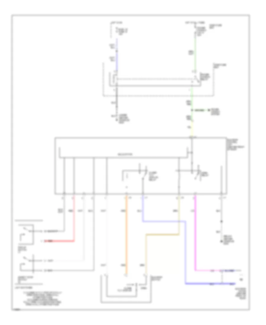
POWER TOP/SUNROOF Power Top/Sunroof Wiring Diagrams for Isuzu Rodeo LSE 2001 List of elements for Power Top/Sunroof Wiring Diagrams for Isuzu Rodeo LSE 2001: 24 (1) closed in tilt (pop-up) & fully open positions. open in all other positions (2) closed during opening, fully open, & closing positions. open in all other positions. (below center console) g302 (under center console) g302 Close/ tilt (pop-up) Close/ tilt (pop-up) relay Dash fuse box Elec. ig fuse 15 15a Hot at all times Hot in on J-1 J-2 Limit switches Open Open relay Pop-up switch (1) Power window c.b. 21 30a Power window relay Power window system Red Safety stop switch (2) Solid state Sun roof control unit (center front of roof) Sun roof motor (center front of roof) Sun roof switch
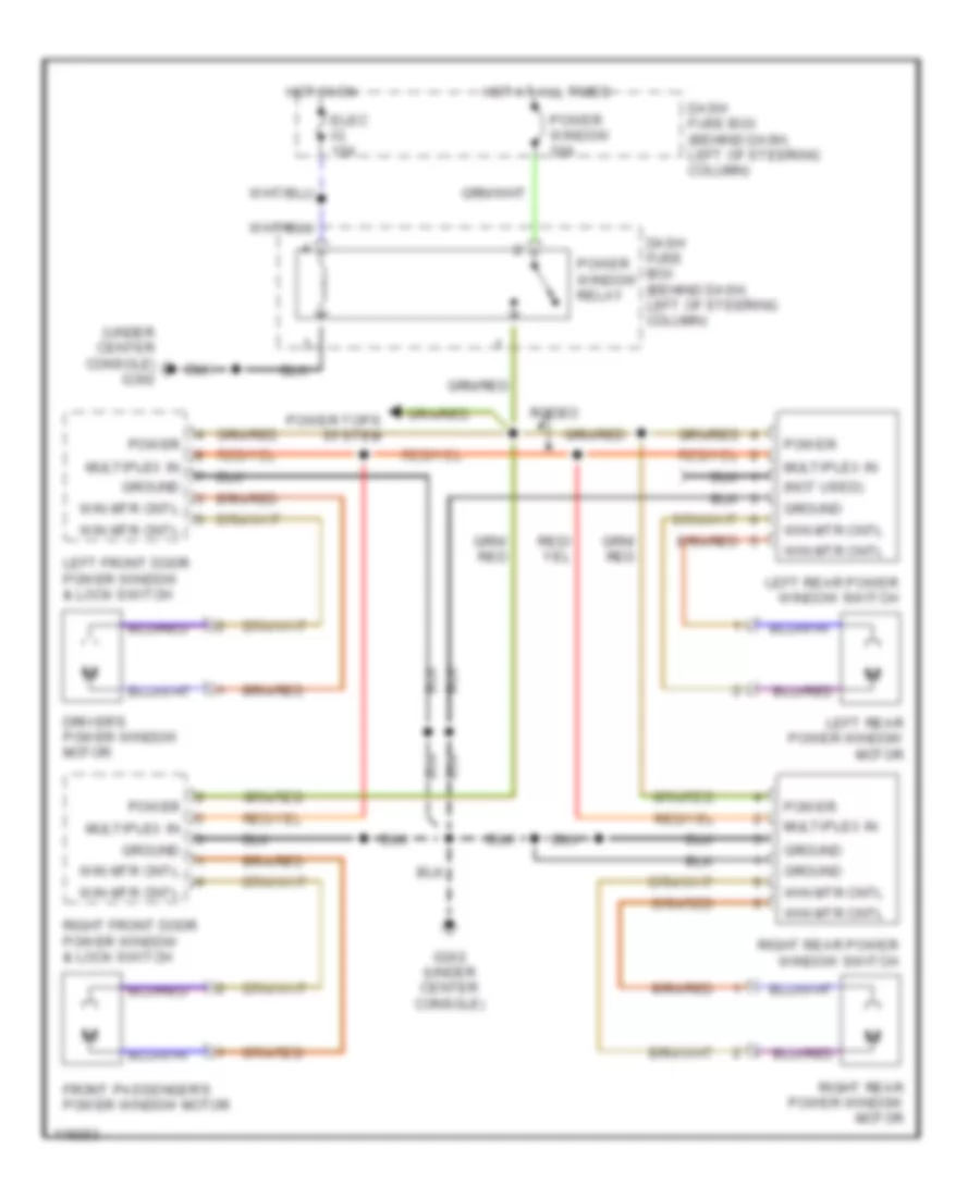
POWER WINDOWS Power Window Wiring Diagram for Isuzu Rodeo LSE 2001 List of elements for Power Window Wiring Diagram for Isuzu Rodeo LSE 2001: 23 (not used) (under center console) g302 Dash fuse box (behind dash, left of steering column) Driver's power window motor Elec ig 15a Front passenger's power window motor G302 (under center console) Ground Hot at all times Hot in on Left front door power window & lock switch Left rear power window motor Left rear power window switch Multiplex in Power Power tops system Power window 30a Power window relay Right front door power window & lock switch Right rear power window motor Right rear power window switch Rodeo Win mtr cntl
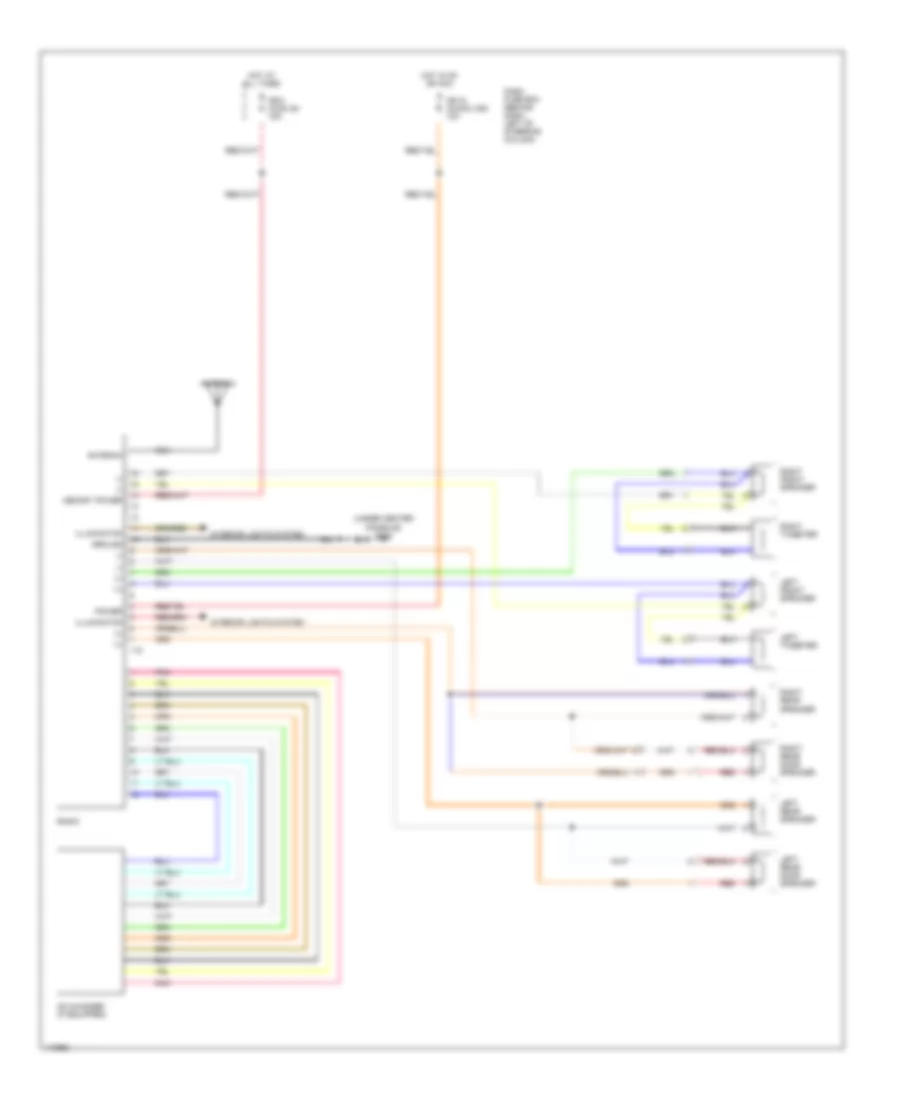
RADIO Radio Wiring Diagrams for Isuzu Rodeo LSE 2001 List of elements for Radio Wiring Diagrams for Isuzu Rodeo LSE 2001: 29 (-) antenna power illuminaton (+) (+) (-) (under center console) g302 Antenna Cb-18 (audio) acc 10a Cb-2 (audi) b+ 15a Cd changer (if equipped) Dash fuse box (behind dash, left of steering column) Hot at all times Hot in on or acc I-15 Illuminaton ground (-) (-) (+) (+) Interior lights system Left front speaker Left rear door speaker Left rear speaker Left tweeter Memory power Nca Pnk Radio Red Right front speaker Right rear door speaker Right rear speaker Right tweeter
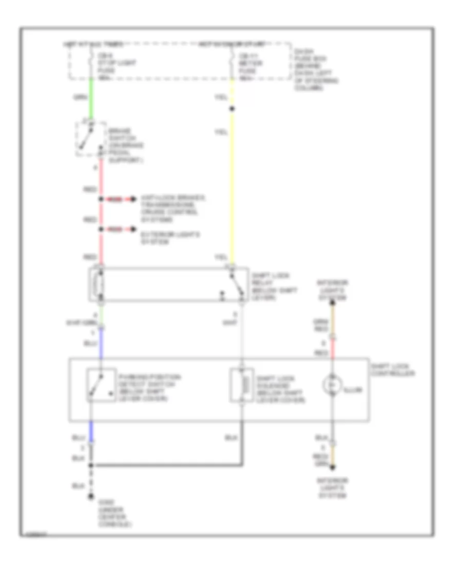
SHIFT INTERLOCKS Shift Interlock Wiring Diagram for Isuzu Rodeo LSE 2001 List of elements for Shift Interlock Wiring Diagram for Isuzu Rodeo LSE 2001: 16 Anti-lock brakes, transmissions, cruise control systems Brake switch (on brake pedal support) Cb-11 meter fuse 10a Cb-6 stop light fuse 15a Dash fuse box (behind dash, left of steering column) Exterior lights system G302 (under center console) Hot at all times Hot in on or start Illum Interior lights system Parking position detect switch (below shift lever cover) Red Shift lock controller Shift lock relay (below shift lever) Shift lock solenoid (below shift lever cover)
STARTING/CHARGING
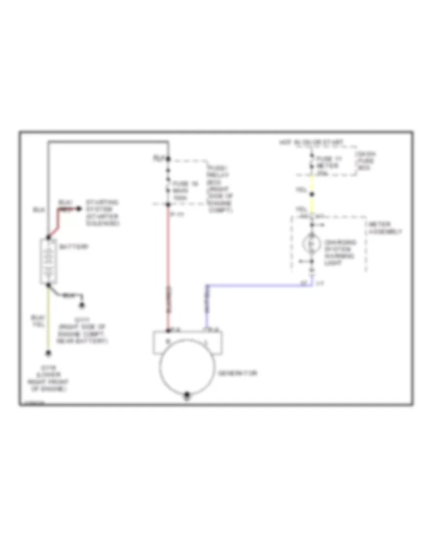
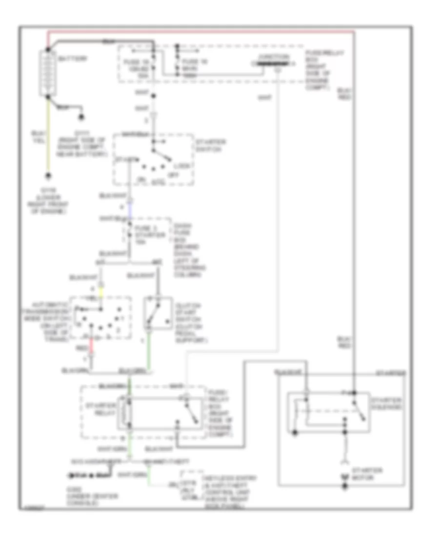
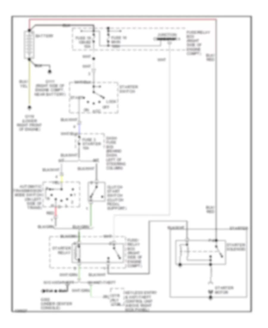
2.2L 2.2L, Charging Wiring Diagram for Isuzu Rodeo LSE 2001 List of elements for 2.2L, Charging Wiring Diagram for Isuzu Rodeo LSE 2001: 16 Battery Charging system warning light Dash fuse box Fuse 11 meter 15a Fuse 16 main 100a Fuse/ relay box (right side of engine compt) G111 (right side of engine compt, near battery) G119 (lower right front of engine) Generator Hot in on or start I-1 Meter assembly P-11 P-8 P-9 Starting system (starter solenoid) Starting Wiring Diagram for Isuzu Rodeo LSE 2001 List of elements for Starting Wiring Diagram for Isuzu Rodeo LSE 2001: 31 A/t Acc Automatic transmission mode switch (on left side of trans) Battery Clutch start switch (clutch pedal support) Dash fuse box (behind dash, left of steering column) Fuse 16 main 100a Fuse 19 ign-b2 50a Fuse 3 starter 10a Fuse/ relay box (right side of engine compt) Fuse/relay box (right side of engine compt) G111 (right side of engine compt, near battery) G119 (lower right front of engine) G302 (under center console) Junction connector a Keyless entry & anti-theft control unit (above right kick panel) Lock M/t Off P-4 Red Rly ctrl Start Starter Starter motor Starter relay Starter solenoid Starter switch Str W/ anti-theft W/o anti-theft
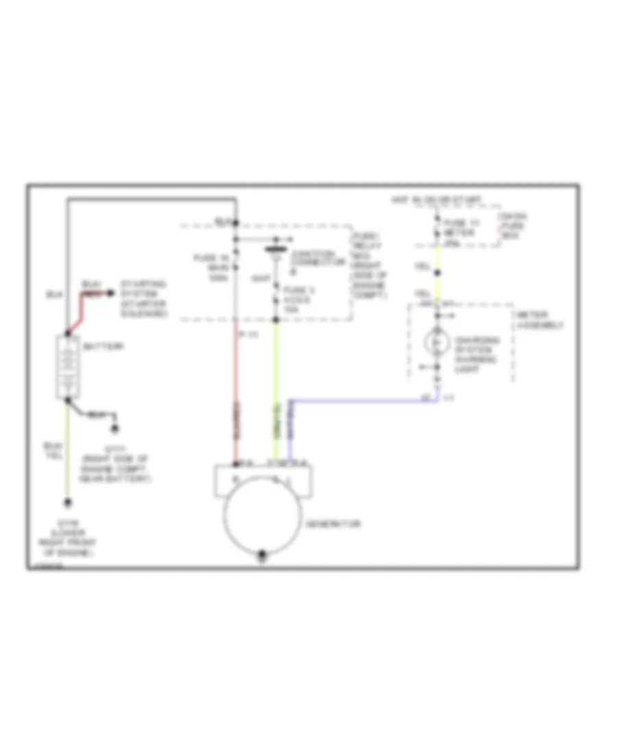
3.2L 3.2L, Charging Wiring Diagram for Isuzu Rodeo LSE 2001 List of elements for 3.2L, Charging Wiring Diagram for Isuzu Rodeo LSE 2001: 18 Battery Charging system warning light Dash fuse box Fuse 11 meter 15a Fuse 16 main 100a Fuse 3 acg-s 10a Fuse/ relay box (right side of engine compt) G111 (right side of engine compt, near battery) G119 (lower right front of engine) Generator Hot in on or start I-1 Junction connector b Meter assembly P-11 P-8 P-9 Starting system (starter solenoid) Starting Wiring Diagram for Isuzu Rodeo LSE 2001 List of elements for Starting Wiring Diagram for Isuzu Rodeo LSE 2001: 31 A/t Acc Automatic transmission mode switch (on left side of trans) Battery Clutch start switch (clutch pedal support) Dash fuse box (behind dash, left of steering column) Fuse 16 main 100a Fuse 19 ign-b2 50a Fuse 3 starter 10a Fuse/ relay box (right side of engine compt) Fuse/relay box (right side of engine compt) G111 (right side of engine compt, near battery) G119 (lower right front of engine) G302 (under center console) Junction connector a Keyless entry & anti-theft control unit (above right kick panel) Lock M/t Off P-4 Red Rly ctrl Start Starter Starter motor Starter relay Starter solenoid Starter switch Str W/ anti-theft W/o anti-theft
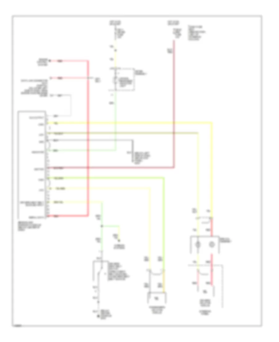
SUPPLEMENTAL RESTRAINTS Supplemental Restraint Wiring Diagram for Isuzu Rodeo LSE 2001 List of elements for Supplemental Restraint Wiring Diagram for Isuzu Rodeo LSE 2001: 28 (below center console) g302 (below left side of dash, above kick panel) g202 Air bag readiness indicator light Cb-11 meter fuse 15a Cb-22 srs fuse 10a Dash fuse box (behind dash, left of steering column) Data link connector (dlc) (partial) (on lower left side of dash, near engine hood release lever) Dlc output Driver's inflator module Driver's seat belt buckled input Driver's seat belt switch (open w/seat belt buckled) (in driver's seat belt buckle) Engine control system Gnd High Hot in on or start I-1 Ignition Indicator Low Meter assembly Only Passenger's inflator module Red Sensing and diagnostic module (below center of dash) Serial data Srs coil assembly Steering wheel Warning systems
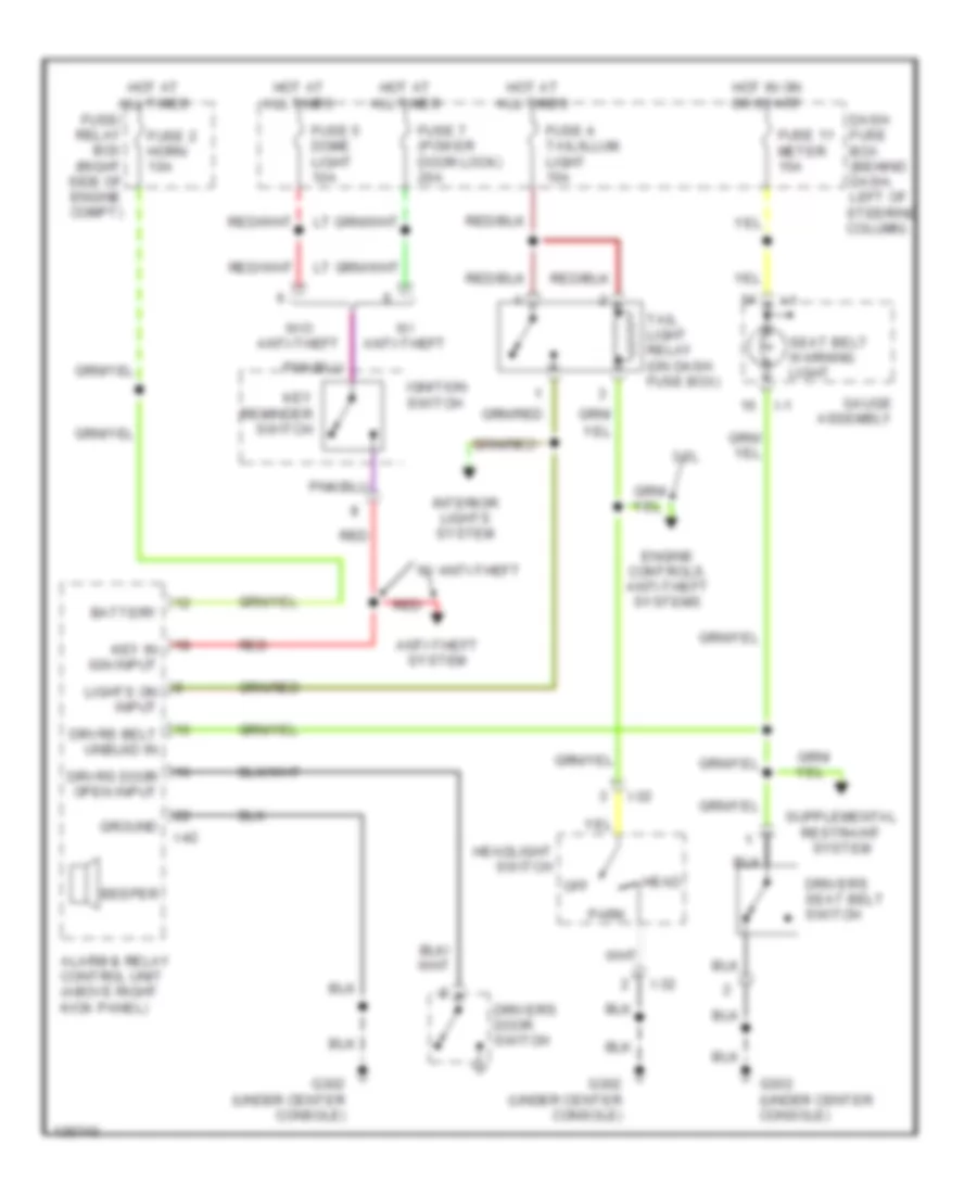
WARNING SYSTEMS Warning System Wiring Diagrams for Isuzu Rodeo LSE 2001 List of elements for Warning System Wiring Diagrams for Isuzu Rodeo LSE 2001: 38 3.2l Alarm & relay control unit (above right kick panel) Anti-theft system Battery Beeper Dash fuse box (behind dash, left of steering column) Driver's door switch Driver's seat belt switch Drvrs door open input Engine controls, anti-theft systems Fuse 11 meter 15a Fuse 2 horn 10a Fuse 4 tail/illum. light 15a Fuse 5 dome light 10a Fuse 7 (power door lock) 20a Fuse/ relay box (right side of engine compt) G302 (under center console) Gauge assembly Ground Head Headlight switch Hot at all times Hot in on or start I-1 I-32 I-42 Ignition switch Interior lights system Key in ign input Key reminder switch Lights on input Off Park Red Seat belt warning light Tail light relay (on dash fuse box) W/ anti-theft W/o anti-theft
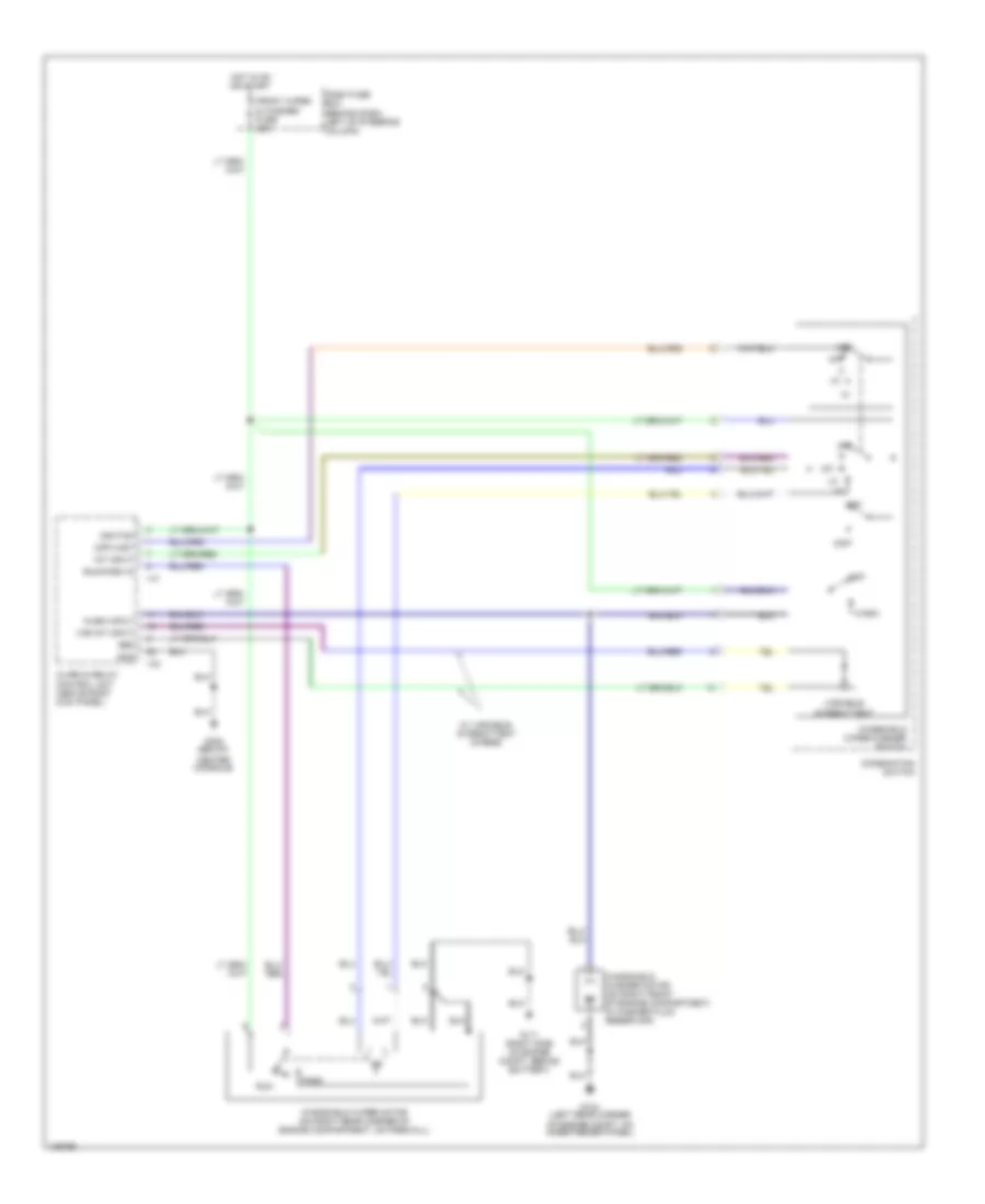
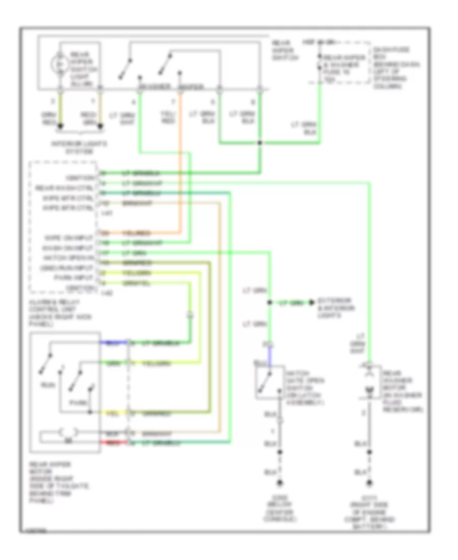
WIPER/WASHER Front Wiper/Washer Wiring Diagram for Isuzu Rodeo LSE 2001 List of elements for Front Wiper/Washer Wiring Diagram for Isuzu Rodeo LSE 2001: 30 (off) mist Alarm & relay control unit (above right kick panel) Center console) Combination switch Dash fuse box (behind dash, left of steering column) Front wiper & washer fuse 20a G104 (left rear corner of engine compt, on inner fender panel) G111 (right side of engine compt, behind battery) G302 (below Gnd Hot in on or start I-41 I-42 Ignition Int Int input Mist Off Park Ref Run Run/park in Var int input Variable intermittent W/ variable intermittent wipers Wash Wash input Windshield washer motor (on right front of engine compartment, in washer fluid reservoir) Windshield wiper motor (on right rear corner of engine compartment, on firewall) Windshield wiper/washer switch Rear Wiper/Washer Wiring Diagram for Isuzu Rodeo LSE 2001 List of elements for Rear Wiper/Washer Wiring Diagram for Isuzu Rodeo LSE 2001: 28 (gnd) run input Alarm & relay control unit (above right kick panel) Dash fuse box (behind dash, left of steering column) Exterior & interior lights G111 (right side of engine compt, behind battery) G302 (below center console) Hatch gate open switch (on latch assembly) Hatch open in Hot in on I-41 I-42 Ignition Interior lights system Park Park input Rear wash ctrl Rear washer motor (in washer fluid reservoir) Rear wiper & washer fuse 16 10a Rear wiper motor (inside right side of tailgate, behind trim panel) Rear wiper switch Rear wiper switch light (illum) Red Run Wash on input Washer Wipe mtr ctrl Wipe on input Wiper