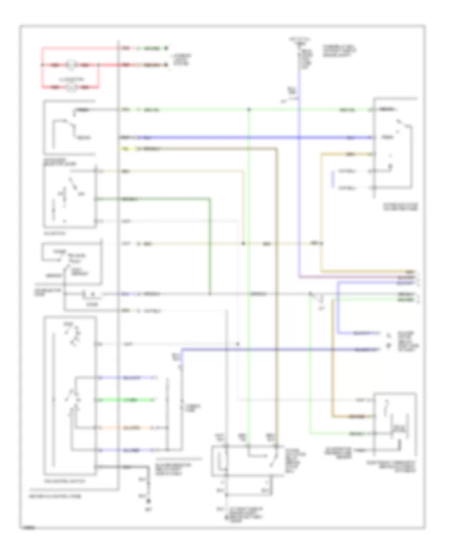
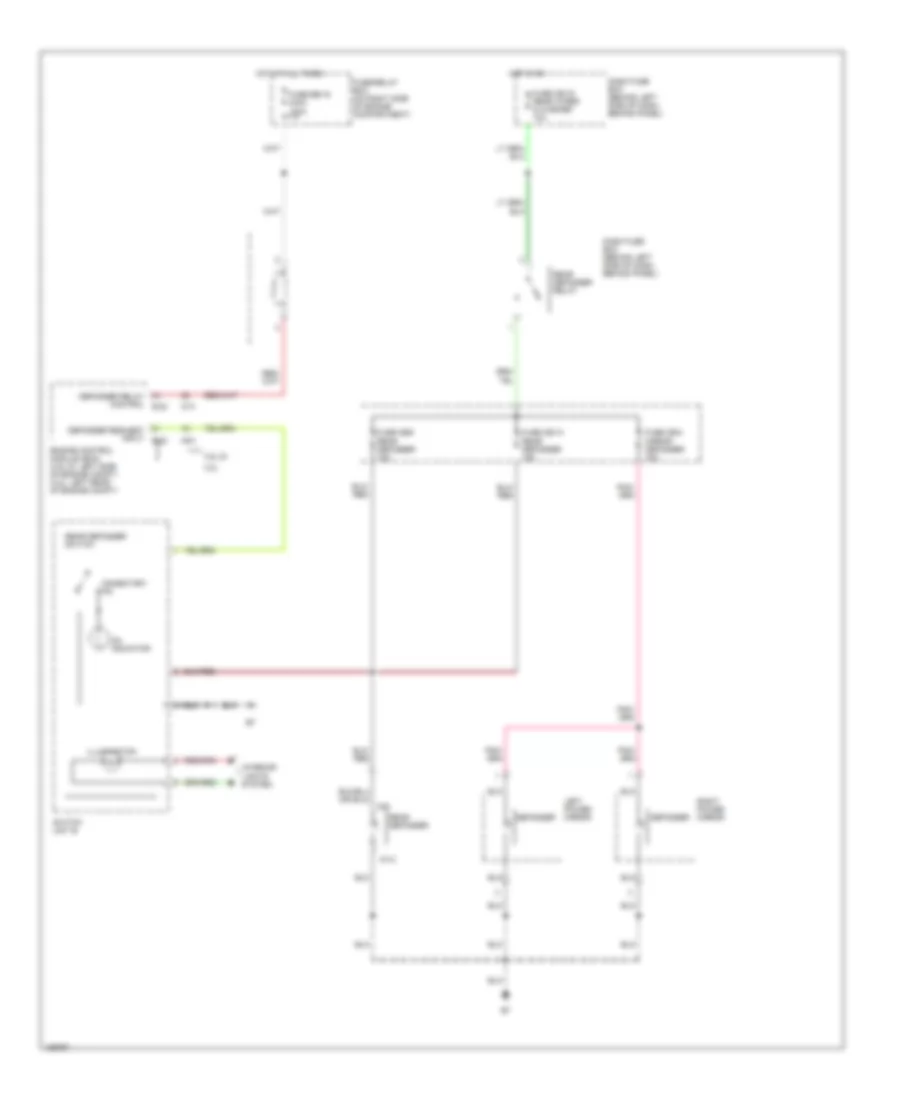
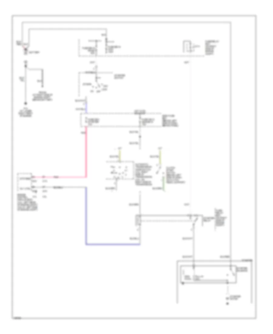
AIR CONDITIONING
Heater Wiring Diagram for Isuzu Rodeo S 2004

List of elements for Heater Wiring Diagram for Isuzu Rodeo S 2004:
- B07
- Blower motor (below right side of dash)
- Blower resistor (below right side of dash)
- C36/p6 (at right side of engine compt, behind battery)
- Cb 15 elec ig fuse 10a
- Dash fuse box (behind left side of dash, behind panel)
- Eb 16 main fuse 100a
- Eb 5 blower fuse 15a
- Eb 6 blower fuse 15a
- Fan control switch
- Fuse/relay box (on right side of engine compartment)
- Heater a/c control panel
- Heater-a/c relay
- Hot at all times
- Hot in on
- Illumination
- Interior lights system
- J/c a
- Off
- Red
- Thermo fuse
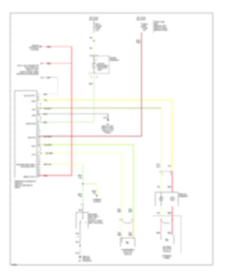
3.2L
3.2L, Manual A/C Wiring Diagram (1 of 2) for Isuzu Rodeo S 2004
List of elements for 3.2L, Manual A/C Wiring Diagram (1 of 2) for Isuzu Rodeo S 2004:
- (at right side of engine compt, behind battery) c36/p6
- A/c switch
- A/t
- Air selector knob
- Air source selector lever
- B07
- Bi-level
- Blower motor (below right side of dash)
- Blower resistor (below right side of dash)
- Defrost
- Diode
- Eb 20 (cond fan) fuse 30a
- Electronic thermostat (behind glove box, on plenum)
- Evaporator temperature sensor
- Face
- Fan control switch
- Foot
- Foot/ defrost
- Fresh
- Fuse/relay box (on right side of engine compt)
- Heater a/c control panel
- Hot at all times
- Illumination
- Intake actuator (on heater case)
- Intake actuator relay (behind glove box)
- Interior lights system
- Nca
- Off
- Recirc
- Red
- Solid state
- Thermo fuse
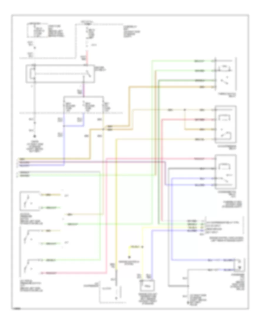
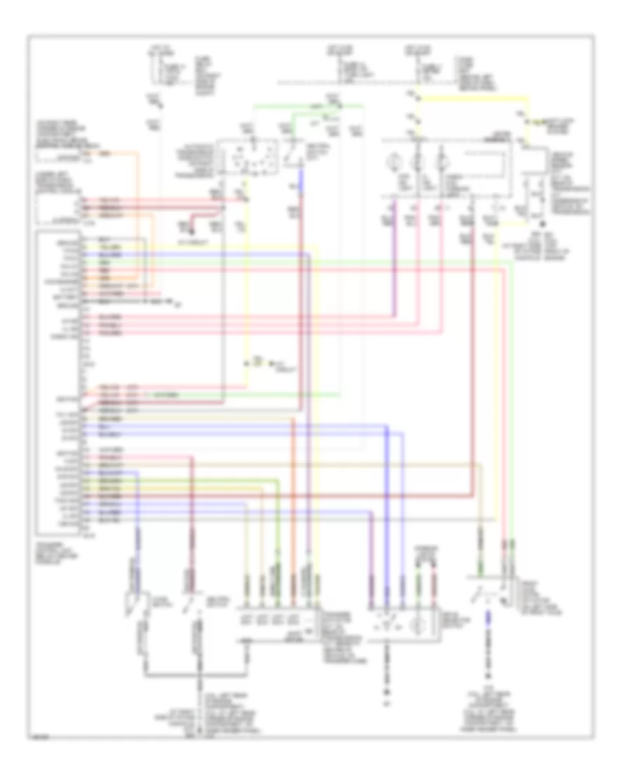
3.2L, Manual A/C Wiring Diagram (2 of 2) for Isuzu Rodeo S 2004
List of elements for 3.2L, Manual A/C Wiring Diagram (2 of 2) for Isuzu Rodeo S 2004:
- (at right side of engine compt, behind battery) p6/c36
- (left rear of engine compt)
- A/c compressor
- A/c compressor relay
- A/c compressor relay ctrl
- A/c dual pressure switch (behind left side of radiator grille)
- A/c on input
- A/c triple pressure switch (a/t) (behind left side of radiator grille)
- A/t
- C36/p6 (at right side of engine compt, behind battery)
- Cb 15 elec ig fuse 10a
- Clutch
- Condenser fan (a/t) (behind right side of radiator grille)
- Condenser fan relay (a/t)
- Dash fuse box (behind left side of dash, behind panel)
- E-21
- Eb 16 main fuse 100a
- Eb 5 blower fuse 15a
- Eb 6 blower fuse 15a
- Eb 7 a/c fuse 10a
- Ect input
- Engine control module (ecm)
- Engine controls system
- Engine coolant temperature (ect) sensor (on right front of engine)
- Fuse/relay box (on right side of engine compt)
- Fuse/relay box (on right side of engine compt)
- Heater- a/c relay
- Hot at all times
- Hot in on
- J/c a
- M/t
- Sens ground
- Thermo switch relay
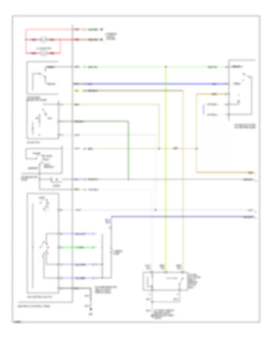
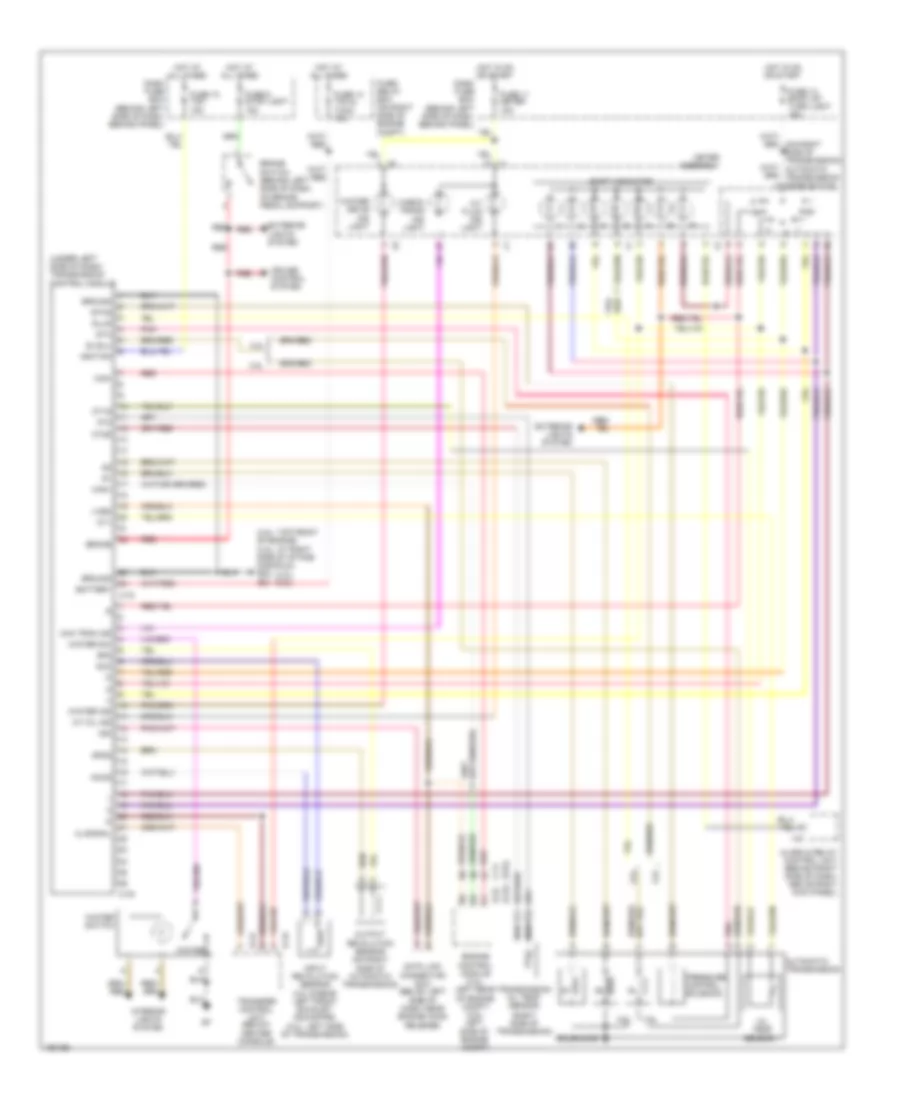
3.5L
3.5L, Manual A/C Wiring Diagram (1 of 2) for Isuzu Rodeo S 2004
List of elements for 3.5L, Manual A/C Wiring Diagram (1 of 2) for Isuzu Rodeo S 2004:
- (at right side of engine compt, behind battery) c36/p6
- A/c switch
- Air selector knob
- Air source selector lever
- B07
- Bi-level
- Blower resistor (below right side of dash)
- Defrost
- Diode
- Face
- Fan control switch
- Foot
- Foot/ defrost
- Fresh
- Heater a/c control panel
- Illumination
- Intake actuator (on heater case)
- Intake actuator relay (behind glove box)
- Interior lights system
- Off
- Recirc
- Red
- Thermo fuse
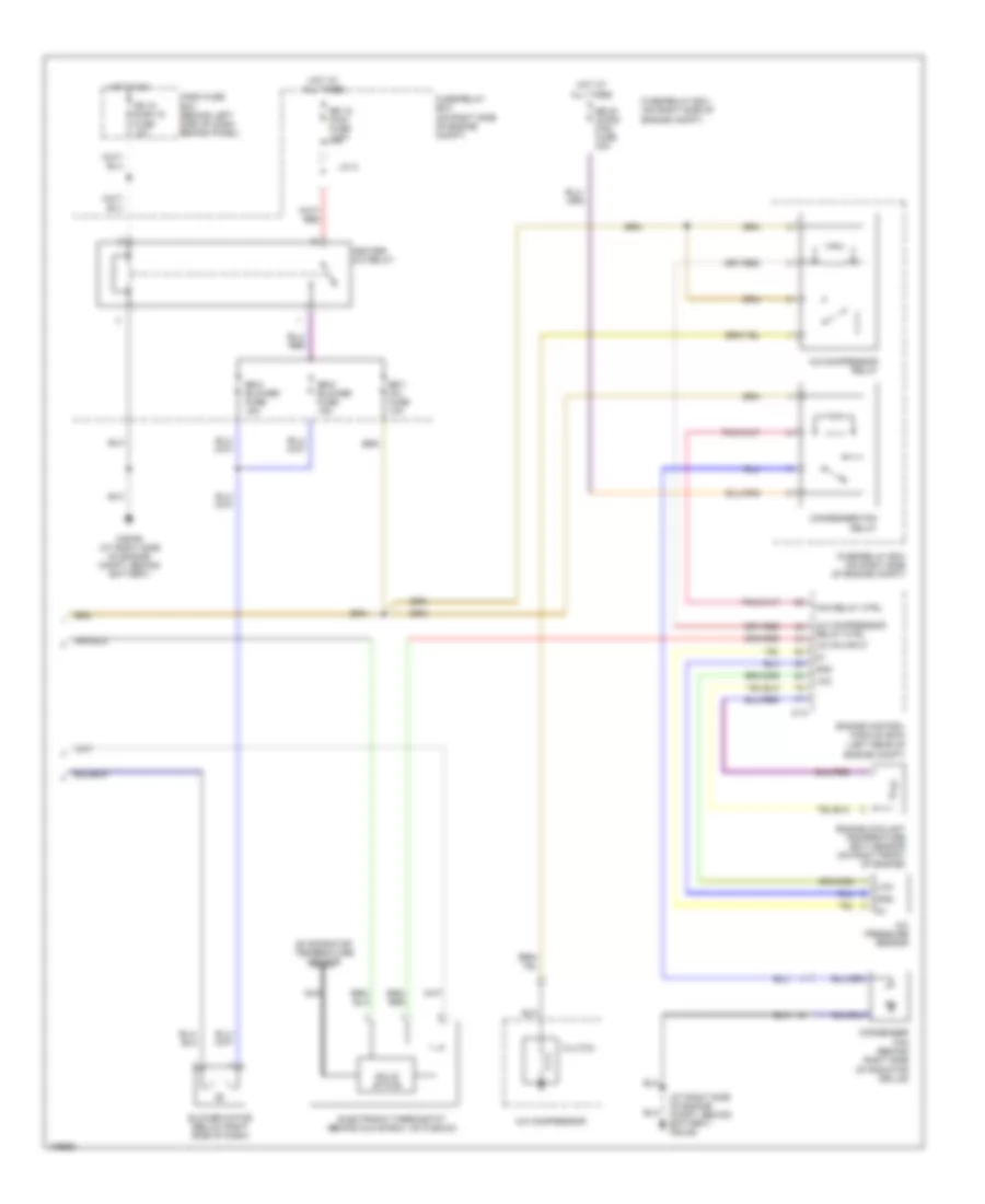
3.5L, Manual A/C Wiring Diagram (2 of 2) for Isuzu Rodeo S 2004
List of elements for 3.5L, Manual A/C Wiring Diagram (2 of 2) for Isuzu Rodeo S 2004:
- (at right side of engine compt, behind battery) p6/c36
- (left rear of engine compt)
- A/c compressor
- A/c compressor relay
- A/c compressor relay ctrl
- A/c on input
- A/c pressure sensor
- Blower motor (below right side of dash)
- C-74
- C36/p6 (at right side of engine compt, behind battery)
- Cb 15 elec ig fuse 10a
- Clutch
- Condenser fan (behind right side of radiator grille)
- Condenser fan relay
- Dash fuse box (behind left side of dash, behind panel)
- Eb 16 main fuse 100a
- Eb 20 (cond fan) fuse 30a
- Eb 5 blower fuse 15a
- Eb 6 blower fuse 15a
- Eb 7 a/c fuse 10a
- Electronic thermostat (behind glove box, on plenum)
- Engine control module (ecm)
- Engine coolant temperature (ect) sensor (on right front of engine)
- Evaporator temperature sensor
- Fan relay ctrl
- Fuse/relay box (on right side of engine compt)
- Fuse/relay box (on right side of engine compt)
- Gnd
- Heater- a/c relay
- Hot at all times
- Hot in on
- J/c a
- Nca
- Solid state
- Vcc
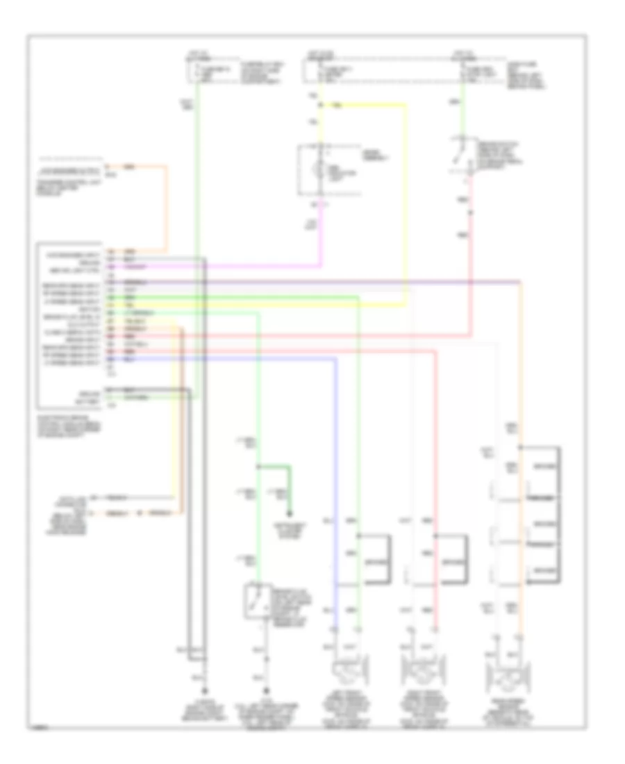
ANTI-LOCK BRAKES
Anti-lock Brakes Wiring Diagram for Isuzu Rodeo S 2004
List of elements for Anti-lock Brakes Wiring Diagram for Isuzu Rodeo S 2004:
- 4wd engaged input
- 4wd engaged output
- Abs ind light ctrl
- Abs indicator light
- B-42
- Battery
- Braided
- Brake fluid level in
- Brake fluid level switch (on left rear of engine compt, in brake fluid reservoir)
- Brake input
- Brake switch (behind left side of dash, on brake pedal support)
- C-16 (3.2l: left rear corner of engine compt, on inner fender panel) (3.5l: left rear of engine compt)
- C-36/p-6 (right side of engine compt, behind battery)
- C-4
- C-5
- Class 2 serial data
- Dash fuse box (behind left side of dash, behind panel)
- Data link connector (dlc) (below left side of dash, near engine hood release)
- Dlc output
- Electronic brake control module (ebcm) (on right rear corner of engine compt)
- Fuse cb-11 meter 15a
- Fuse cb-6 stop light 15a
- Fuse eb-18 abs 50a
- Fuse/relay box (on right side of engine compartment)
- Ground
- Hot at all times
- Hot in on or start
- I-1
- Ignition
- Instrument cluster system
- Left front speed sensor (4wd: on inside of front knuckle spindle) (2wd: on inside of front wheels)
- Lf speed sens input
- Meter assembly
- Rear spd sens input
- Rear speed sensor (beneath rear of vehicle, on top of differential)
- Red
- Rf speed sens input
- Right front speed sensor (4wd: on inside of front knuckle spindle) (2wd: on inside of front wheels)
- Transfer control unit (below center console)
ANTI-THEFT
Forced Entry Wiring Diagram (1 of 2) for Isuzu Rodeo S 2004
List of elements for Forced Entry Wiring Diagram (1 of 2) for Isuzu Rodeo S 2004:
- Act pos locked
- Act pos unlocked
- Anti- theft fuse 23 10a
- Anti-theft horn (on right rear corner of engine compartment)
- Anti-theft indicator light
- Battery input
- C36/p6 (at right side of engine compt, behind battery)
- Dash fuse box (behind left side of dash, behind panel)
- Diode box 5
- Disarm lock input
- Disarm unlock input
- Door locks system
- Door/hatch open in
- Dr door act ctrl
- Engine hood input
- Engine hood switch (at right rear corner of engine compt)
- Exterior lights system
- Fuse/relay box (on right side of engine compartment)
- Ground
- Hatch gate open switch (inside top center of tailgate, on latch assembly)
- Headlight rly ctrl
- Headlights system
- Horn fuse 2 10a
- Hot at all times
- Hot in acc or on
- Ignition input
- Ignition switch
- Interior lights system
- J/c b
- Key in ignition
- Key reminder switch
- Key rod act posit
- Keyless entry & anti-theft control unit (behind right side of dash, above kick panel)
- Left front door switch
- Left rear door switch
- Lock input
- Lock/unlock input
- Power door lock fuse 7 20a
- Red
- Right front door switch
- Right rear door switch
- Security horn ctrl
- Security ind ctrl
- Switch unit a
- Taillight relay
- Unlock input
- Warning system
- Wiper/ washer system
Forced Entry Wiring Diagram (2 of 2) for Isuzu Rodeo S 2004
List of elements for Forced Entry Wiring Diagram (2 of 2) for Isuzu Rodeo S 2004:
- (momentary)
- Driver's door key detect & actuator position switches
- Left front door key detect switch (inside rear of left front door, on key cylinder)
- Left front door lock actuator (in left front door)
- Left rear door actuator position switch
- Left rear door lock actuator (in left rear door)
- Lock
- Right front door actuator position switch
- Right front door key detect switch
- Right front door lock actuator
- Right rear door actuator position switch
- Right rear door lock actuator
- Tailgate actuator position switch
- Tailgate door lock actuator (at center of tailgate)
- Tailgate key detect switch (in center of tailgate)
- Unlock
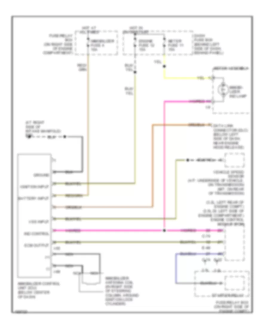
Immobilizer Wiring Diagram for Isuzu Rodeo S 2004
List of elements for Immobilizer Wiring Diagram for Isuzu Rodeo S 2004:
- (+)
- (-)
- (3.2l: left rear of engine compt) (3.5l di: left side of engine compartment) engine control module (ecm)
- (at right side of intake manifold) e30
- 3.2l
- 3.5l
- Battery input
- C-74
- Dash fuse box (behind left side of dash, behind panel)
- Data link connector (dlc) (below left side of dash, near engine hood release)
- E-22
- E-48
- Ecm output
- Engine fuse 12 15a
- Fuse/relay box (on right side of engine compartment)
- Fuse/relay box (on right side of engine compt)
- Ground
- Hot at all times
- Hot in on or start
- I-55
- I-9
- I-99
- Ignition input
- Immobi- lizer ind lamp
- Immobilizer antenna coil (in right side of steering column, around ignition lock cylinder)
- Immobilizer control unit (icu) (below center of dash)
- Immobilizer fuse 4 10a
- Ind control
- Meter assembly
- Meter fuse 11 15a
- Nca
- Starter relay
- Vehicle speed sensor (a/t: underside of vehicle, on transmission) (m/t: on rear of transmission)
- Vss input
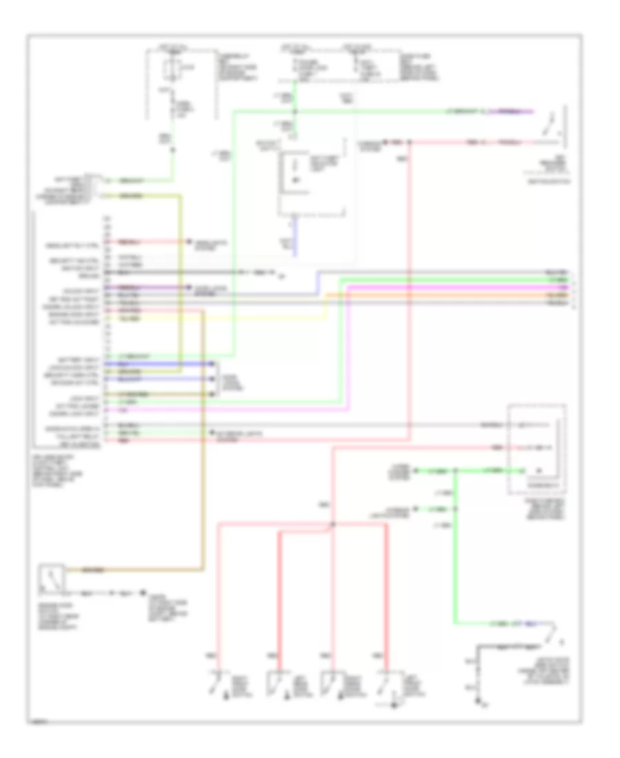
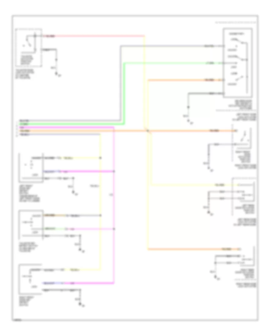
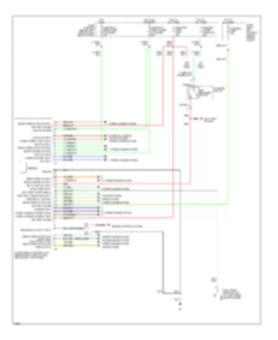
BODY CONTROL MODULES
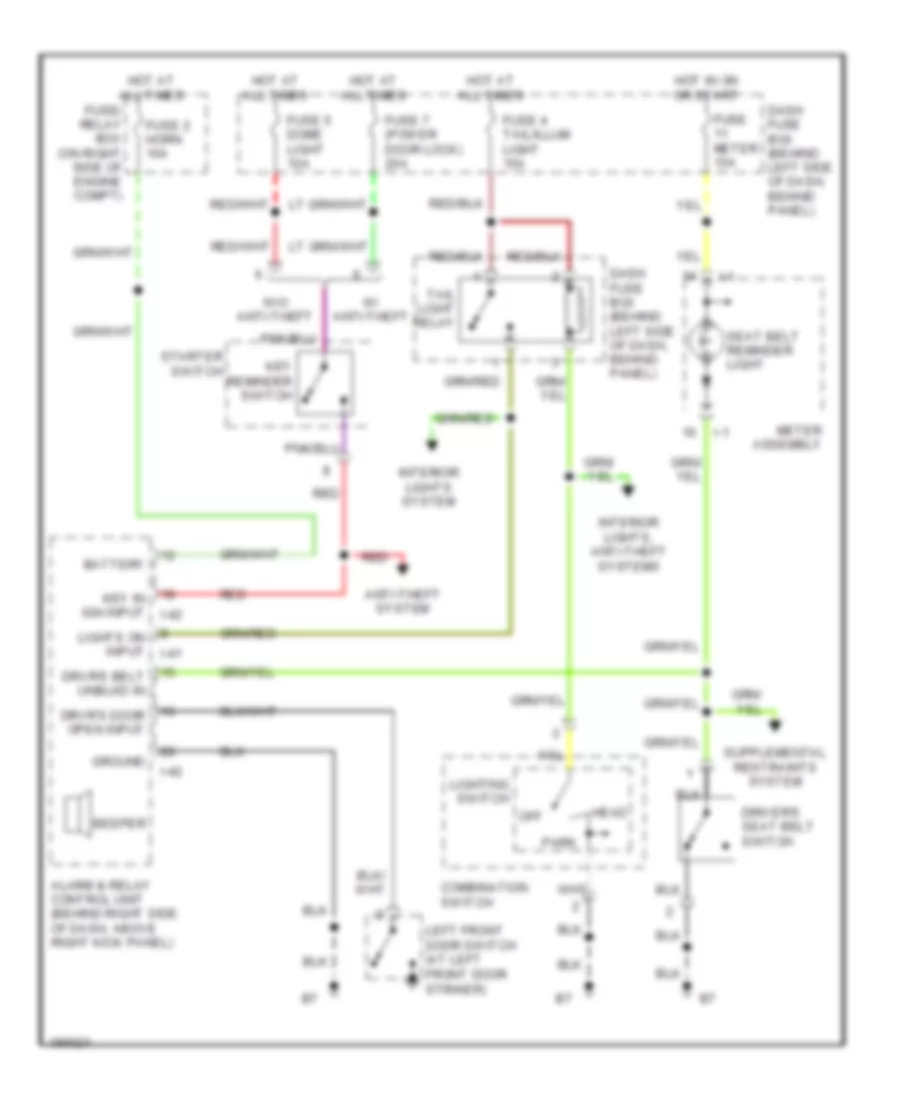
Body Control Modules Wiring Diagram for Isuzu Rodeo S 2004
List of elements for Body Control Modules Wiring Diagram for Isuzu Rodeo S 2004:
- 3.2l a/t
- 3.2l m/t
- Alarm & relay control unit (behind right side of dash, above right kick panel)
- Anti-theft system
- Battery power
- Beeper
- Dash fuse box (behind left side of dash, behind panel)
- Engine controls system
- Exterior, interior lights systems
- Fuse cb-16 rear wiper & washer 10a
- Fuse cb-17 front wiper & washer 20a
- Fuse cb-5 dome light 10a
- Fuse cb-7 power door lock 20a
- Fuse eb-2 horn 10a
- Fuse/ relay box (on right side of engine compt)
- Ground
- Ground or up shift input
- Hatch open input
- Horn output
- Horn relay control
- Horns system
- Hot at all times
- Hot in on
- Hot in on or start
- I41
- I42
- Ignition input
- Ignition power
- Key in ignition input
- Key reminder switch
- Left front door open in
- Left front door switch (at left front door striker)
- Lights on input
- Off input
- Rear washer control
- Rear washer on input
- Rear wiper motor control
- Rear wiper motor ctrl
- Rear wiper motor ctrl shift ind(1) (or up shift ctrl)
- Rear wiper on input
- Red
- Seat belt unbuckled input
- Starter switch
- Transmissions system
- W/ anti- theft
- W/o anti- theft
- Warning system
- Washer input
- Wiper intermittent input
- Wiper run/park input
- Wiper variable intermittent
- Wiper/washer system
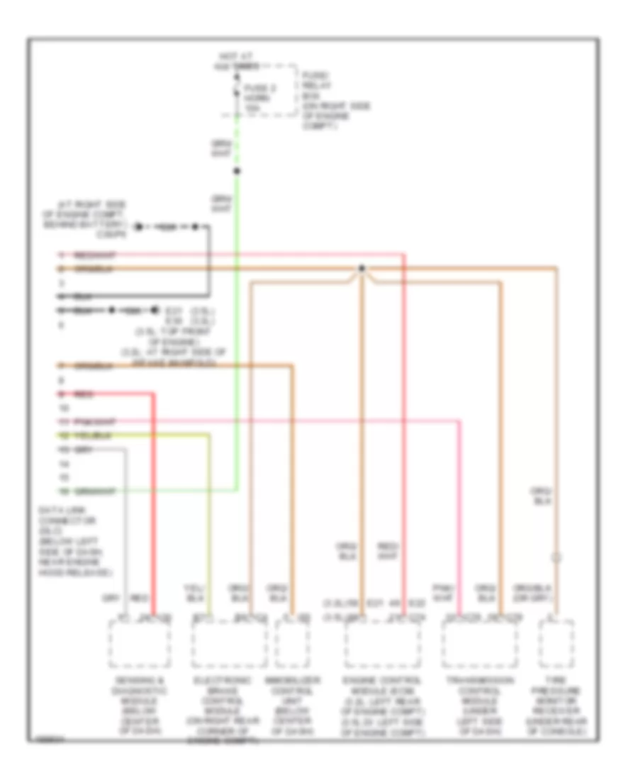
COMPUTER DATA LINES
Computer Data Lines Wiring Diagram for Isuzu Rodeo S 2004
List of elements for Computer Data Lines Wiring Diagram for Isuzu Rodeo S 2004:
- (3.2l)
- (3.5l)
- (3.5l) (3.2l)
- (at right side of engine compt, behind battery) c36/p6
- C4 b6
- C74
- C78
- C79
- Data link connector (dlc) (below left side of dash, near engine hood release)
- E21
- E21 e30 (3.5l: top front of engine) (3.2l: at right side of intake manifold)
- E22
- Electronic brake control module (on right rear corner of engine compt)
- Engine control module (ecm) (3.2l: left rear of engine compt) (3.5l di: left side of engine compt)
- Fuse 2 horn 10a
- Fuse/ relay box (on right side of engine compt)
- Hot at all times
- I30
- I55
- Immobilizer control unit (below center of dash)
- Red
- Sensing & diagnostic module (below center of dash)
- Tire pressure monitor receiver (under rear of console)
- Transmission control module (under left side of dash)
CRUISE CONTROL
3.2L
3.2L, Cruise Control Wiring Diagram for Isuzu Rodeo S 2004
List of elements for 3.2L, Cruise Control Wiring Diagram for Isuzu Rodeo S 2004:
- (below center of dash) immobilizer control unit
- Acceleration position sensor assembly
- Acceleration sensors
- Ap sen1 gnd
- Ap sen2 gnd
- Ap sensor 1
- Ap sensor 2
- Ap sensor 3
- Aps3 gnd
- B-19
- Brake sw in
- Brake switch (behind left side of dash, on brake pedal support)
- C-4
- C16 (at left rear corner of engine compt, on inner fender panel)
- Cancel
- Cancel in
- Cb-11 meter fuse 15a
- Cb-12 engine ig fuse 15a
- Cb-14 back-up/ turn light fuse 15a
- Cb-6 stop light fuse 15a
- Clutch switch (m/t) (behind left side of dash, on clutch pedal support)
- Cruise brake
- Cruise control main switch
- Cruise control switch
- Cruise lmp
- Cruise set light
- Cruise sw
- Dash fuse box (behind left side of dash, behind panel)
- Drive input
- E-21
- E-22
- E28 (at left side of intake manifold)
- E30 (at right side of intake manifold)
- Eb-17 ecm fuse 30a
- Ecm main relay
- Electronic brake control module (ebcm) (on right rear corner of engine compartment)
- Engine control module (ecm) (left rear of engine compt)
- Engine controls system
- Fuse/relay box (on right side of engine compt)
- Gnd
- Hot at all times
- Hot in on or start
- I-2
- I-55
- I-9
- Ign
- Ign feed
- Illumination
- Ind on/off cruise
- Interior lights system
- Meter assembly
- Nca
- On switch
- Pnk
- Red
- Ref volt
- Res/acc
- Set/cst
- Solid state sensor
- Speedometer
- Srs coil assembly
- Steering wheel
- Switch unit a
- Th val mtr+
- Throttle position sensor 1
- Throttle position sensor 2
- Throttle val-
- Throttle valve assembly
- Throttle valve motor
- Tps 1 sign
- Tps1 gnd
- Tps2 gnd
- Tps2 sign
- Transfer control unit (below center console)
- Vehicle speed sensor (underside of vehicle, on transmission)
- Vss in
3.5L
3.5L, Cruise Control Wiring Diagram for Isuzu Rodeo S 2004
List of elements for 3.5L, Cruise Control Wiring Diagram for Isuzu Rodeo S 2004:
- (below center of dash) immobilizer control unit
- (top front of engine)
- 5v reference
- Acceleration pedal position sensor (above accelerator pedal)
- Acceleration sensors
- B-19
- Brake input
- Brake sw in
- Brake switch (behind left side of dash, on brake pedal support)
- C-4
- C-74
- Cancel
- Cancel input
- Cruise control main switch
- Cruise control switch
- Cruise on in
- Cruise set light
- Dash fuse box (behind left side of dash, behind panel)
- E-48
- E21
- E21 (top front of engine)
- Ecm
- Ecm main relay
- Electronic brake control module (ebcm) (on right rear corner of engine compt)
- Engine control module (ecm) (left side of engine compt)
- Engine controls system
- Fuse-11 meter fuse 15a
- Fuse-12 engine ig fuse 15a
- Fuse-14 back-up/ turn light fuse 15a
- Fuse-17 ecm fuse 30a
- Fuse-6 stop light fuse 15a
- Fuse/relay box (on right side of engine compt)
- Fwd (+)
- Ground
- Hot at all times
- Hot in on or start
- I-2
- I-55
- I-9
- Ign
- Ignition input
- Ignition input ignition input
- Illumination
- Immobilizer in
- Ind control
- Ind on/off cruise
- Interior lights system
- Meter assembly
- Nca
- Pnk
- Red
- Res/acc
- Rev (-)
- Sensor gnd
- Set/cst
- Signal
- Solid state sensor
- Speedometer
- Srs coil assembly
- Steering wheel
- Switch unit a
- Throttle position sensor 1
- Throttle position sensor 2
- Throttle valve assembly
- Throttle valve motor
- Tps 1 signal
- Tps 2 sig
- Transfer control unit (below center console)
- Vehicle speed sensor (vss) (a/t: underside of vehicle, on transmission) (m/t: on rear of transmission)
- Vss in
DEFOGGERS
Defoggers Wiring Diagram for Isuzu Rodeo S 2004
List of elements for Defoggers Wiring Diagram for Isuzu Rodeo S 2004:
- 3.2l
- 3.5l di
- C-74
- Dash fuse box (behind left side of dash, behind panel)
- Defogger
- Defogger relay control e-22
- Defogger request input e-22
- Engine control module (ecm) (3.5l di: left side of engine compt) (3.2l: left rear of engine compt)
- Fuse cb-10 rear defogger 15a
- Fuse cb-16 rear wiper & washer 10a
- Fuse cb-8 mirror defogger 10a
- Fuse cb-9 rear defogger 15a
- Fuse eb-16 main 100a
- Fuse/relay box (on right side of engine compartment)
- G-12
- G-9
- Hot at all times
- Hot in on
- Illumination
- Interior lights system
- Left power mirror
- Momentary on
- On indicator
- Rear defogger
- Rear defogger relay
- Rear defogger switch
- Right power mirror
- Switch unit b
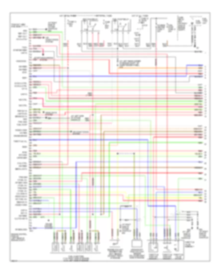
ENGINE PERFORMANCE
3.2L
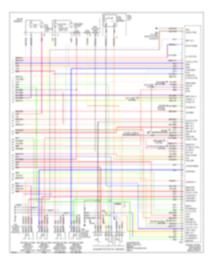
3.2L, Engine Performance Wiring Diagram (1 of 4) for Isuzu Rodeo S 2004
List of elements for 3.2L, Engine Performance Wiring Diagram (1 of 4) for Isuzu Rodeo S 2004:
- (at left rear corner of engine compt, on inner fender panel) c16
- (at left side of intake manifold)
- (at right side of intake manifold) e30
- (m/t)
- 2 fuel inj
- 3 fuel inj
- 4 fuel inj
- 5 inj ctrl
- A/c clutch
- A/c req
- Air conditioning system
- Ap sen1 gnd
- Ap sen2 gnd
- B1s1
- B1s2
- B2s1
- B2s2
- Brake sw in
- C.q. sign in
- Ckp in
- Clutch sw in
- Crankshaft position (ckp) sensor (on lower right side of engine)
- Cruise brake
- Cruise control system
- E-21
- E28
- E28 (at left side of intake manifold)
- E30 (at right side of intake manifold)
- Ecm main relay
- Ect in
- Engine control module (left rear of engine compt)
- Engine coolant temperature (ect) sensor (on right front of engine)
- Etc gnd
- Fuel injectors (1,3,5: right side of engine) (2,4,6: left side of engine)
- Fuel pump
- Fuel pump fuse 12 20a
- Fuel pump relay
- Fuel tank unit
- Fuse 13 ecm 10a
- Fuse 15 ign b1 60a
- Fuse ecm 30a
- Fuse/ relay box (on right side of engine compt)
- Gnd
- Headlights system
- Ho2s b1s2 -
- Ho2s2 h gnd
- Hot at all times
- Iat in
- Ig coil2 ctrl
- Ig coil3 ctrl
- Ign feed
- Ind ctrl
- J/c b
- Knock sig in
- Lights on
- Maf in
- Map in
- N01 fuel inj
- O2 sens heater fuse 11 20a
- Pins not used: 8-12, 35-36
- Pnk
- Psp sw in
- Red
- Ref volt
- Res/acc in
- Serial data
- Starter feed
- Starting/charging system
- Tach
- Throttle position sensor 1
- Throttle position sensor 2
- Throttle val
- Throttle valve assembly
- Throttle valve motor
- Tps1 gnd
- Tps2 gnd
- Tps2 sign
- Vapor sen
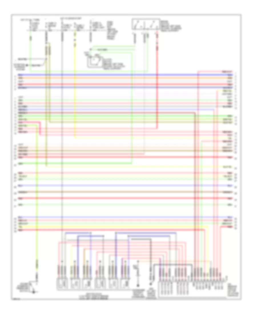
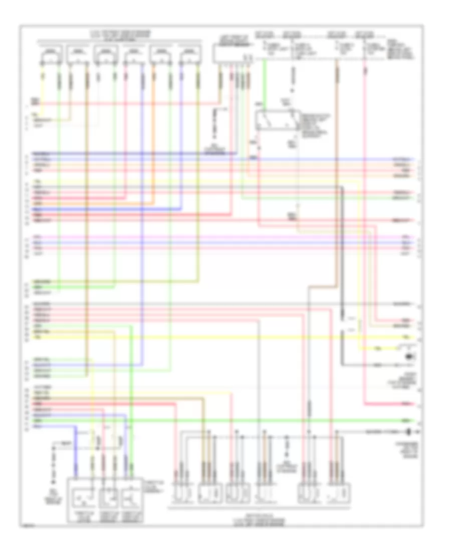
3.2L, Engine Performance Wiring Diagram (2 of 4) for Isuzu Rodeo S 2004
List of elements for 3.2L, Engine Performance Wiring Diagram (2 of 4) for Isuzu Rodeo S 2004:
- 1,3,5 coil in
- 2,4,6 coil in
- Brake switch (behind left side of dash, on brake pedal support)
- Clutch switch (behind left side of dash, on clutch pedal support)
- Coil 1 ctrl
- Coil 2 ctrl
- Coil 3 ctrl
- Coil 4 ctrl
- Coil 5 ctrl
- Coil 6 ctrl
- Condenser (0n right front of condenser)
- Dash fuse box (behind left side of dash, behind panel)
- E-16
- E-17
- E-18
- E29 (at left side of intake manifold)
- Est 11
- Est 12
- Est 13
- Est 21
- Est 22
- Est 23
- Fuse 11 meter 15a
- Fuse 12 engine ig 15a
- Fuse 13 ig coil 15a
- Fuse 14 back up/ turn light 15a
- Fuse 6 stop light 15a
- Gnd
- Hot at all times
- Hot in on or start
- Ign
- Ignition coils (1,3,5: right side of engine) (2,4,6: left side of engine)
- Ion sensing module (on top of intake manifold)
- Ioncq1
- Ionk1
- Pnk
- Power steering pressure switch
- Red
- Starting/ charging system
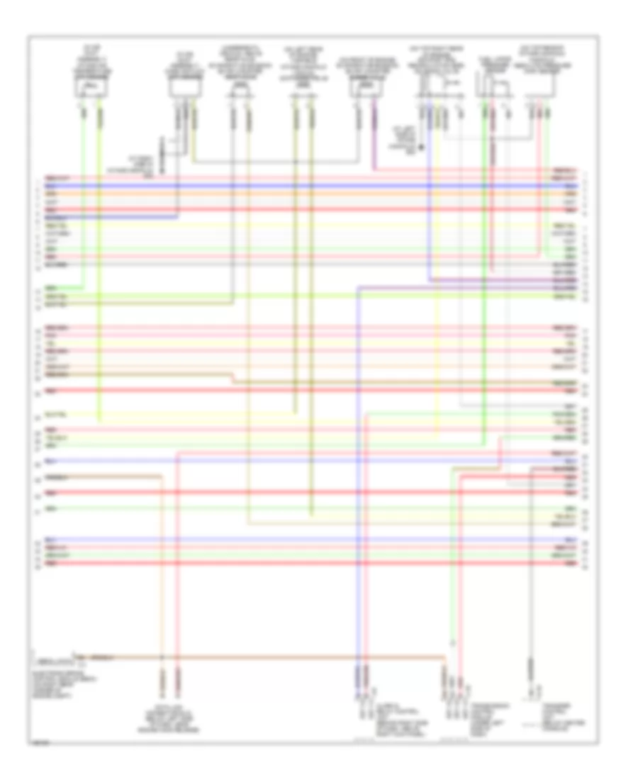
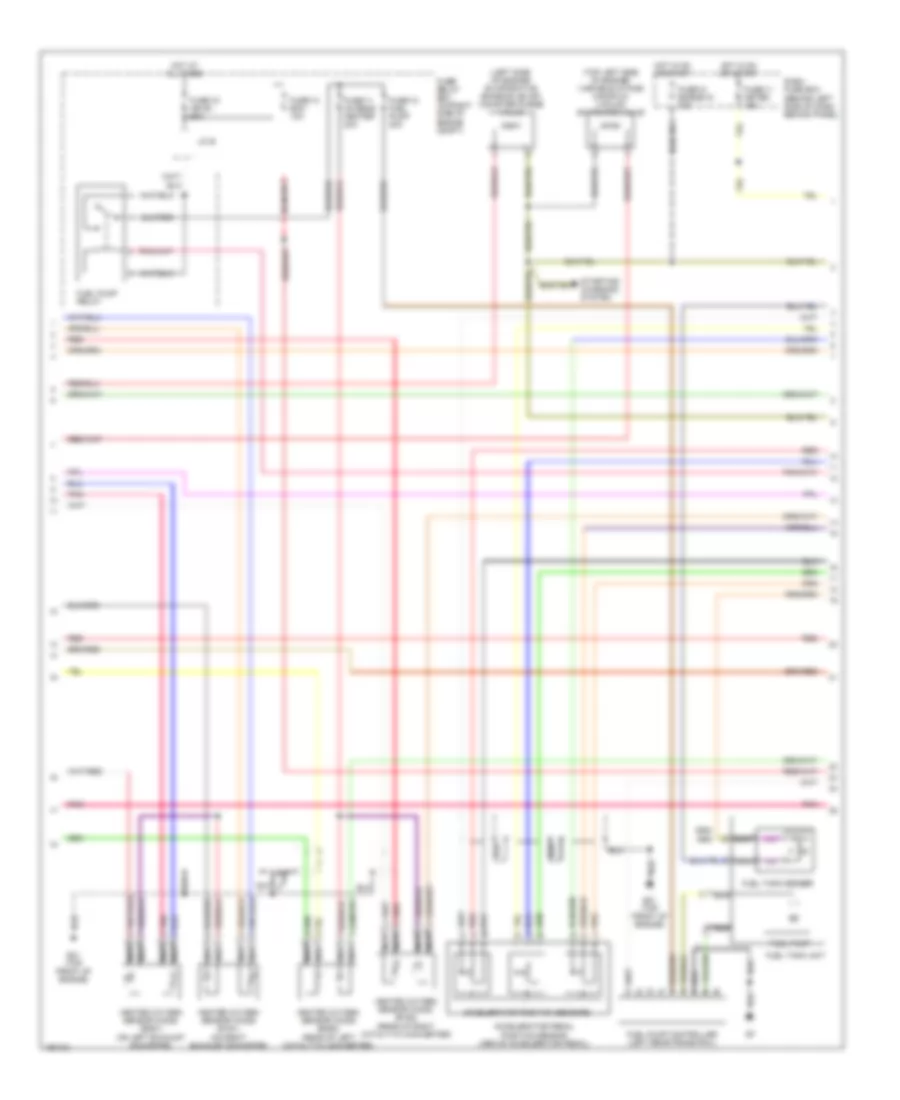
3.2L, Engine Performance Wiring Diagram (3 of 4) for Isuzu Rodeo S 2004
List of elements for 3.2L, Engine Performance Wiring Diagram (3 of 4) for Isuzu Rodeo S 2004:
- (at left side of intake manifold) e28
- (in air duct assembly) intake air temperature (iat) sensor
- (in air duct assembly) mass air flow (maf) sensor
- (on front of engine) evaporative emission (evap) canister purge valve
- (on left rear of engine) variable intake manifold vacuum switching valve
- (on top rear of intake manifold) manifold absolute pressure (map) sensor
- (on top right rear of engine) exhaust gas recirculation (egr) solenoid valve
- (underneath vehicle, above rear axle) evaporative emission (evap) canister vent valve
- Alarm & relay control unit (behind right side of dash, above right kick panel)
- B-19
- C-4
- C-78
- Data link connector (dlc) (below left side of dash, near engine hood release)
- Electronic brake control module (ebcm) (on right rear corner of engine compt)
- Est 11
- Est 12
- Est 13
- Fuel vapor pressure sensor
- I-42
- Pnk
- Red
- Serial data
- Transfer control unit (below center console)
- Transmission control module (under left side of dash)
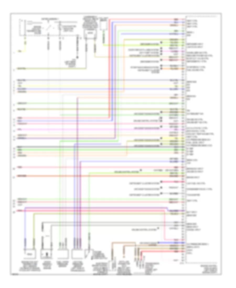
3.2L, Engine Performance Wiring Diagram (4 of 4) for Isuzu Rodeo S 2004
List of elements for 3.2L, Engine Performance Wiring Diagram (4 of 4) for Isuzu Rodeo S 2004:
- "u/s" ind
- (at right side of intake manifold)
- 6 fuel inj
- Accelerator pedal position sensor (above accelerator pedal)
- Accelerator positioin sensors
- Anti-theft system
- Ap sensor 1
- Ap sensor 2
- Ap sensor 3
- Aps3 gnd
- B1s1
- B1s2
- B2s1
- B2s2
- Can +
- Can cut val
- Can-
- Cruise control system
- Cruise lmp
- Cruise sw
- Defog req
- Defog rly
- Defogger system
- Defogger sysyem
- Dlc
- E-22
- E28 (at left side of intake manifold)
- E30
- E30 (at right side of intake manifold)
- Ect out
- Egr ctrl hi
- Egr in
- Eng coolant temp gauge
- Engine control module (ecm) (left rear of engine compt)
- Evap purge
- F-1
- Fuel gauge
- Fuel sen
- Fuel tank sender
- Fuel tank unit
- Gnd
- Ground
- Heated oxygen sensor (ho2s) (b1s1) (in right front exhaust pipe)
- Heated oxygen sensor (ho2s) (b1s2) (rear of right catalytic converter)
- Heated oxygen sensor (ho2s) (b2s1) (in left front exhaust pipe)
- Heated oxygen sensor (ho2s) (b2s2) (rear of left catalytic converter)
- Ho2s b1s1 +
- Ho2s b1s1 -
- Ho2s b1s2 +
- Ho2s b2s1 +
- Ho2s b2s1 -
- Ho2s b2s2 +
- Ho2s b2s2 -
- Ho2s1 h gnd
- Ho2s1h gnd
- I-1
- I-2
- I-9
- Ig coil1 ctrl
- Ig coil4 ctrl
- Ig coil5 ctrl
- Ig coil6 ctrl
- Ign feed
- Imm ind
- Immobil in
- Low fuel warning light
- Malfunc- tion indicator light (mil)
- Meter assembly
- Mil ind ctrl
- Nca
- Pnk
- Red
- Reduced power ind
- Ref volt
- Sens gnd
- St relay ctrl
- Starting/charging system
- Tach- ometer
- Th val mtr
- Tps 1 sign
- Up ind in
- Vapor press
- Vim vsv ctrl
3.5L
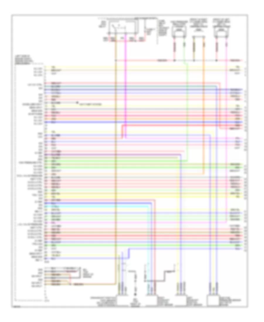
3.5L, Engine Performance Wiring Diagram (1 of 4) for Isuzu Rodeo S 2004
List of elements for 3.5L, Engine Performance Wiring Diagram (1 of 4) for Isuzu Rodeo S 2004:
- (front of left cylinder head) left oil control valve
- (front of right cylinder head) right oil control valve
- (left side of engine compt) engine control module (ecm)
- 5v ref
- Anti-theft system
- C-74
- Crankshaft position (ckp) sensor (on lower right side of engine)
- E-48
- E21 (top front of engine)
- Ecm main relay
- Evap purge
- Fuse-17 ecm 30a
- Fuse/ relay box (on right side of engine compt)
- Gnd
- Heat ctrl
- High fuel pressure sensor (on top of engine)
- High pressure ctrl
- High pressure regulator valve
- Hot in on or start
- Ig coil1 ctrl
- Ig coil2 ctrl
- Ig coil3 ctrl
- Ig coil4 ctrl
- Ig coil5 ctrl
- Ig coil6 ctrl
- Ign input
- Immobilizer input
- Inj high
- Inj low
- L oil valve pressure
- Left camshaft position (cmp) sensor
- Nca
- Pnk
- R oil valve pressure
- Red
- Rev (+)
- Rev (-)
- Right camshaft position (cmp) sensor
- Sens gnd
- Sens input
- Sig
- Tps 1 sig
- Tps 2 sig
- Vcc
- Vim vcv ctrl
3.5L, Engine Performance Wiring Diagram (2 of 4) for Isuzu Rodeo S 2004
List of elements for 3.5L, Engine Performance Wiring Diagram (2 of 4) for Isuzu Rodeo S 2004:
- (1,3,5: top right side of engine) (2,4,6: top left side of engine) fuel injectors
- (left front of engine compt) maf/iat sensor
- Brake switch (behind left side of dash, on brake pedal support)
- Condenser (on top front of engine)
- Dash fuse box (behind left side of dash, behind panel)
- E21 (top front of engine)
- E23 (top front of engine)
- Fuse-13 ig coil 15a
- Fuse-14 back-up/ turn light 15a
- Fuse-3 starter 10a
- Fuse-6 stop light 15a
- Hot in on or start
- Iat
- Ignition coils (1,3,5: right side of engine) (2,4,6: left side of engine)
- Knock sensor 1 (top of engine)
- Nca
- Pnk
- Red
- Throttle position sensor 1
- Throttle position sensor 2
- Throttle valve assembly
- Throttle valve motor
3.5L, Engine Performance Wiring Diagram (3 of 4) for Isuzu Rodeo S 2004
List of elements for 3.5L, Engine Performance Wiring Diagram (3 of 4) for Isuzu Rodeo S 2004:
- (left side of engine) evaporative emission (evap) canister purge valve
- (top left side of engine) variable intake manifold vacuum switching valve
- Accelerator pedal position sensor (above accelerator pedal)
- Accelerator position sensors
- Dash fuse box (behind left side of dash, behind panel)
- E21 (top front of engine)
- Fuel pump
- Fuel pump controller (left rear frame rail)
- Fuel pump relay
- Fuel tank sender
- Fuel tank unit
- Fuse-11 meter 15a
- Fuse-11 o2 sens, heater 20a
- Fuse-12 engine ig 15a
- Fuse-12 fuel pump 20a
- Fuse-13 ecm 10a
- Fuse-15 ign b1 60a
- Fuse/ relay box (on right side of engine compt)
- Heated oxygen sensor (ho2s) (b1s1) (on right exhaust downpipe)
- Heated oxygen sensor (ho2s) (b1s2) (rear of right catalytic converter)
- Heated oxygen sensor (ho2s) (b2s1) (on left exhaust downpipe)
- Heated oxygen sensor (ho2s) (b2s2) (rear of left catalytic converter)
- Hot at all times
- Hot in on or start
- J/c b
- Nca
- Pnk
- Red
- Starting/ charging system
3.5L, Engine Performance Wiring Diagram (4 of 4) for Isuzu Rodeo S 2004
List of elements for 3.5L, Engine Performance Wiring Diagram (4 of 4) for Isuzu Rodeo S 2004:
- (underneath vehicle, above rear axle) evaporative emission (evap) canister vent valve
- 5v ref
- A/c clutch rly ctrl
- A/c pressure sens (-)
- A/c pressure sens (5v)
- A/c pressure sens (vcc)
- A/c request sig
- Air conditioning system
- Anti-theft system
- B6 serial data
- Brake input
- Brake sw input
- C-4
- C-74
- C-78
- C16 (left rear of engine compt)
- Can-h
- Can-l
- Cancel input
- Canl-h
- Canl-l
- Computer data lines system
- Condenser fan rly ctrl
- Coolant temp gauge ctrl
- Cruise control system
- Cruise ind ctrl
- Cruise on input
- Cruise set ind ctrl
- Data link connector (dlc) (below left side of dash, near engine hood release)
- Defogger input
- Defogger rly ctrl
- Defogger system
- Ecm main rly ctrl
- Ect input
- Electronic brake control module (ebcm) (on right rear corner of engine compt)
- Engine control module (ecm) (left side of engine compt)
- Engine coolant temperature (ect) sensor (on rear of engine, in coolant manifold)
- Engine coolant temperature gauge
- Evap cut valve ctrl
- Fuel gauge ctrl
- Fuel level input
- Fuel vapor pressure sensor
- Gnd
- Heat ctrl
- I-1
- I-2
- Ign
- Immobilizer ind ctrl
- Instrument cluster system
- J1850
- Knock sensor 2 (top of engine)
- Lights on input
- Low fuel ind ctrl
- Low fuel pressure sensor (left side of transmission)
- Malfunction indicator light (mil)
- Meter assembly
- Nca
- Pnk
- Power steering pressure (psp) switch
- Red
- Reduced power ind ctrl
- Sens (-)
- Sens (vcc)
- Sens gnd
- Sens input
- Sens sig
- Serial data
- Sig
- Starter rly ctrl
- Starting/charging system
- Tachometer
- Taillight relay
- Transmission control module (under left side of dash)
- Vcc
EXTERIOR LIGHTS
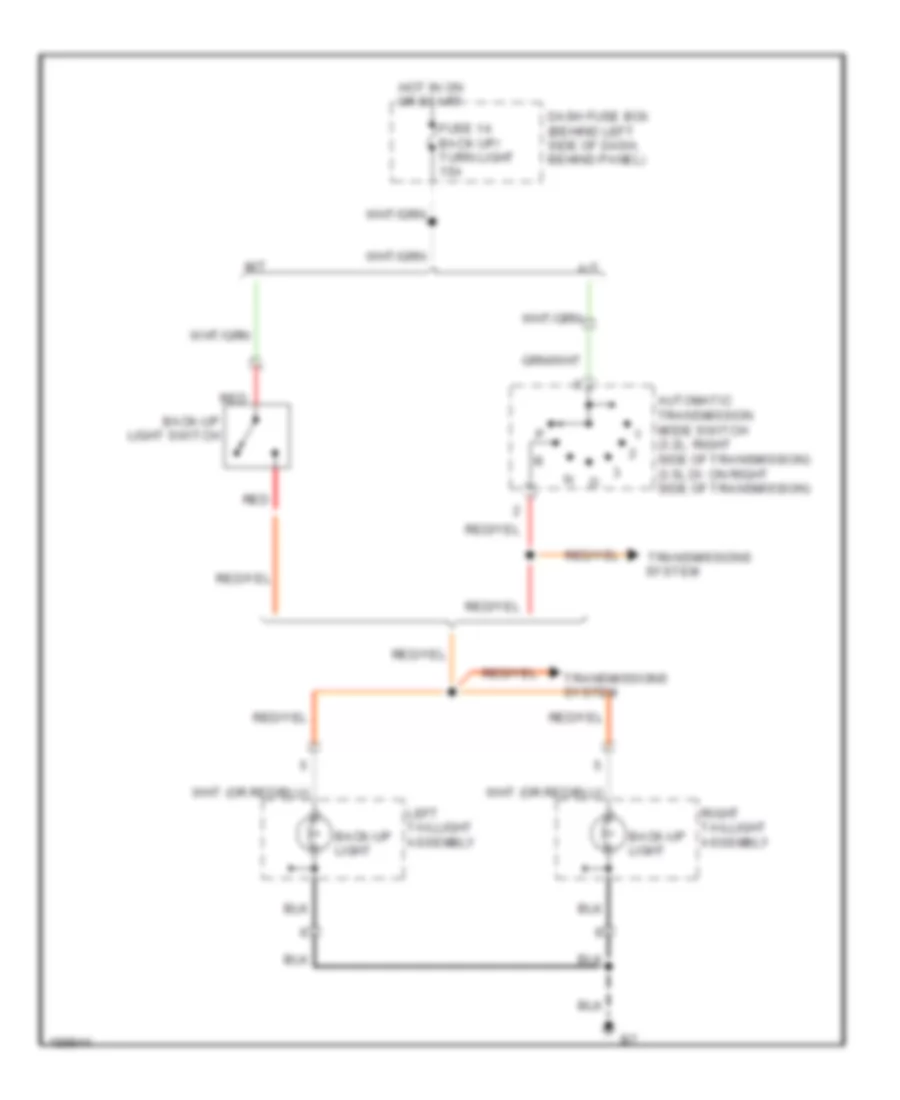
Back-up Lamps Wiring Diagram for Isuzu Rodeo S 2004
List of elements for Back-up Lamps Wiring Diagram for Isuzu Rodeo S 2004:
- A/t
- Automatic transmission mode switch (3.2l: right side of transmission) (3.5l di: on right side of transmission)
- Back-up light
- Back-up light switch
- Dash fuse box (behind left side of dash, behind panel)
- Fuse 14 back up/ turn light 15a
- Hot in on or start
- Left taillight assembly
- M/t
- Red
- Right taillight assembly
- System
- Transmissions
- Transmissions system
Exterior Lamps Wiring Diagram (1 of 2) for Isuzu Rodeo S 2004
List of elements for Exterior Lamps Wiring Diagram (1 of 2) for Isuzu Rodeo S 2004:
- (3.5l di: left rear of engine compt) (3.2l: at left rear corner of engine compt, on inner fender panel) c16
- Brake input
- Combination switch
- Converter (under vehicle, behind left rear wheel)
- Dash fuse box (behind left side of dash, behind panel)
- Flasher unit (above left kick panel)
- Fuse 1 hazard 15a
- Fuse 14 back up/ turn light 15a
- Fuse/relay box (on right side of engine compartment)
- Gnd
- Hazard
- Hazard warning switch
- Hazard warning switch light
- Hot at all times
- Hot in on or start
- I-2
- Ignition
- Interior lights system
- Left
- Left front combination light
- Left turn indicator light
- Left turn sig/haz input
- Left turn sig/haz output
- Light on input
- Light on output
- Meter assembly
- Off
- Output
- Pnk
- Red
- Right
- Right front combination light
- Right turn indicator light
- Right turn sig/haz input
- Right turn sig/haz output
- Trailer connector
- Trailer harness connector (in left "d" pillar, behind trim)
- Turn signal switch
Exterior Lamps Wiring Diagram (2 of 2) for Isuzu Rodeo S 2004
List of elements for Exterior Lamps Wiring Diagram (2 of 2) for Isuzu Rodeo S 2004:
- Brake switch (behind left side of of dash, on brake pedal support)
- Combination switch
- Dash fuse box (behind left side of dash, behind panel)
- Engine controls system
- Fuse 4 tail/illumi light 15a
- Fuse 6 stop light 15a
- Head
- High mount stop light
- Hot at all times
- Interior lights system
- Keyless entry & anti-theft control unit (behind right side of dash, above kick panel)
- Left license light
- Left taillight assembly
- License light
- Lighting switch
- Off
- Park
- Pnk
- Red
- Right license light
- Right taillight assembly
- Shift interlock system
- Stop
- Tail
- Tail/stop light
- Taillight relay
- Transmissions, anti-lock brakes, cruise control systems
- Turn light
- W/ optional spare tire mounted on rear door
- W/o optional spare tire mounted on rear door
GROUND DISTRIBUTION
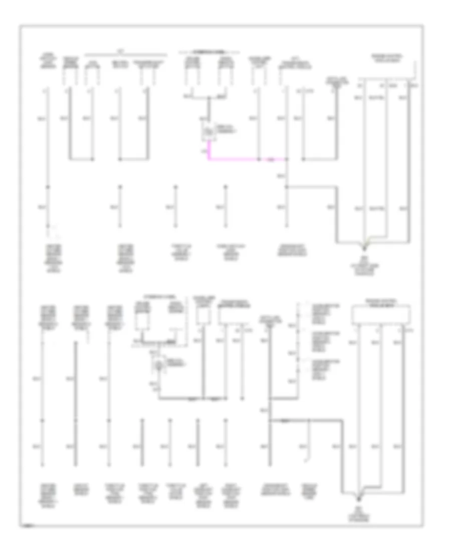
Ground Distribution Wiring Diagram (1 of 3) for Isuzu Rodeo S 2004
List of elements for Ground Distribution Wiring Diagram (1 of 3) for Isuzu Rodeo S 2004:
- (ebcm)
- (on right side of engine compt) fuse/relay box
- (w/ amplifier)
- (w/o amplifier)
- 2-4wd switch
- 3.2l
- 3.2l, w/ a/t
- A/t
- Acceleration pedal position sensor shields
- Alarm & relay control unit
- Amplifier
- B-41
- B07
- Battery
- Brake fluid level switch
- C-4
- C-5
- C16 (3.2l: at left rear corner of engine compt, on inner fender panel) (3.5l: left rear of engine compt)
- Condenser fan
- Condenser fan relay
- Data link connector (dlc)
- Driver's seat belt switch
- E-16
- E-21
- E-22
- E-33
- E28 (3.2l) (at left side of intake manifold)
- E29 (3.2l) (at left side of intake manifold)
- Ecm main relay
- Electronic brake control module
- Electronic brake control module (ebcm)
- Engine control module (ecm)
- Engine hood switch
- Exhaust gas recirculation (egr) solenoid valve
- Front axle motor actuator
- Fuel pump relay
- Heater- a/c relay
- I-1
- I-2
- I-42
- I43 (below left side of dash, above kick panel)
- Ignition coils 1, 3 & 5 shield
- Ignition coils 2, 4 & 6 shield
- Intake actuator relay
- Ion sensing module
- Left foglight
- Left front combination light
- Meter assembly
- Neutral switch
- P06/c36 (at right side of engine compt, behind battery)
- P10 (at lower right front of engine)
- Radio
- Rear defogger switch
- Rear washer motor
- Right foglight
- Right front combination light
- Sensing & diagnostic module (sdm)
- Switch unit b
- Throttle valve assembly assembly shield
- Throttle valve assembly shield
- Tire pressure monitor receiver
- To b07 (diagram 3 of 3)
- Transfer actuator
- Windshield washer motor
- Windshield wiper motor
- Winter switch
Ground Distribution Wiring Diagram (2 of 3) for Isuzu Rodeo S 2004
List of elements for Ground Distribution Wiring Diagram (2 of 3) for Isuzu Rodeo S 2004:
- (a/t) transmission control module
- 4wd switch
- Accelerator position sensor 1 (aps 1) shield
- Accelerator position sensor 2 (aps 2) shield
- Accelerator position sensor 3 (aps 3) shield
- C-74
- C-78
- Crankshaft position (ckp) sensor shield
- Cruise control switch
- Data link connector (dlc)
- E-21
- E-22
- E21 (3.5l) (top front of engine)
- E30 (3.2l) (at right side of intake manifold)
- Engine control
- Heated oxygen sensor (bank 1 sensor 1) shield
- Heated oxygen sensor (bank 1 sensor 2) shield
- Heated oxygen sensor (bank 1 sensors 1 & 2) shield
- Heated oxygen sensor (bank 2 sensor 1) shield
- Heated oxygen sensor (bank 2 sensor 2) shield
- Heated oxygen sensor (bank 2 sensors 1 & 2) shield
- Immobilizer control unit
- Left camshaft position (cmp) sensor shield
- M/t
- Maf/iat sensor shield
- Mass air flow (maf) sensor
- Mass air flow (maf) sensor shield
- Module (ecm)
- Neutral switch
- Radio remote switch
- Right camshaft position (cmp) sensor shield
- Srs coil assembly
- Steering wheel
- Throttle position (tps) sensor 1 shield
- Throttle position (tps) sensor 2 shield
- Throttle valve assembly shield
- Throttle valve motor shield
- Transfer shift actuator
- Transmission control module
- Vehicle speed sensor
- Vehicle speed sensor (vss)
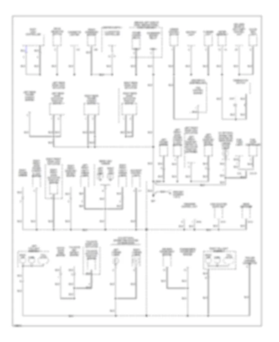
Ground Distribution Wiring Diagram (3 of 3) for Isuzu Rodeo S 2004
List of elements for Ground Distribution Wiring Diagram (3 of 3) for Isuzu Rodeo S 2004:
- (behind left side of dash, behind panel) dash fuse box
- (w/ optional spare tire mounted on rear door) license plate light
- 3.2l
- 3.5l di
- Accessory socket relay
- Ashtray light
- B-42
- B07
- Back up
- Cigarette lighter
- Coil
- Combination switch
- Drive selector switch
- Driver's power seat switch
- Fan control switch
- Flasher unit
- From b07 (diagram 1 of 3)
- Front accessory socket
- Fuel pump controller
- Fuel tank unit
- G-10
- G-12
- Glove box light
- Hatch gate open switch
- Heater-a/c control unit
- High mounted stoplight
- I-2
- I-21
- I-29
- Illumination controller
- J-1
- Keyless entry & anti-theft control unit
- Left front door key detect & actuator position switches
- Left front door key detect switch
- Left front door lock actuator
- Left front door power window & lock switch
- Left front vanity mirror light
- Left license light
- Left map light
- Left power mirror
- Left rear door actuator position switch
- Left rear door lock actuator
- Left rear power window switch
- Left taillight assembly
- Meter assembly
- Mirror control switch
- Passenger's power seat switch
- Power window relay
- Rear defogger
- Rear view mirror
- Right front door actuator position switch
- Right front door key detect switch
- Right front door lock actuator
- Right front door power window & lock switch
- Right front vanity mirror light
- Right license light
- Right map light
- Right power mirror
- Right rear door actuator position switch
- Right rear door lock actuator
- Right rear power window switch
- Right taillight assembly
- Shift lock controller
- Sun roof control unit
- Switch unit a
- Tail/ stop
- Tailgate actuator position switch
- Tailgate door lock actuator
- Tailgate key detect switch
- Trailer harness connector
- Transfer control unit
- Turn
- W/o optional spare tire mounted on rear door
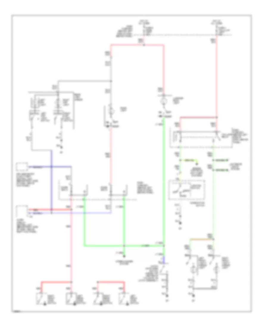
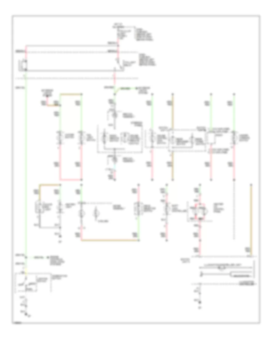
HEADLIGHTS
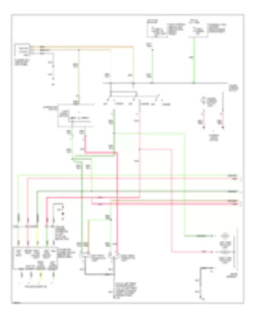
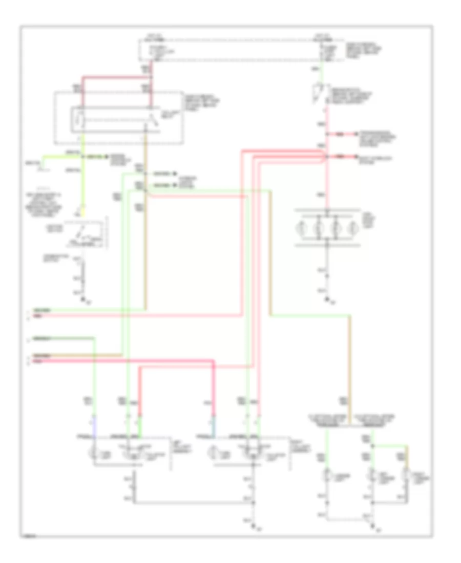
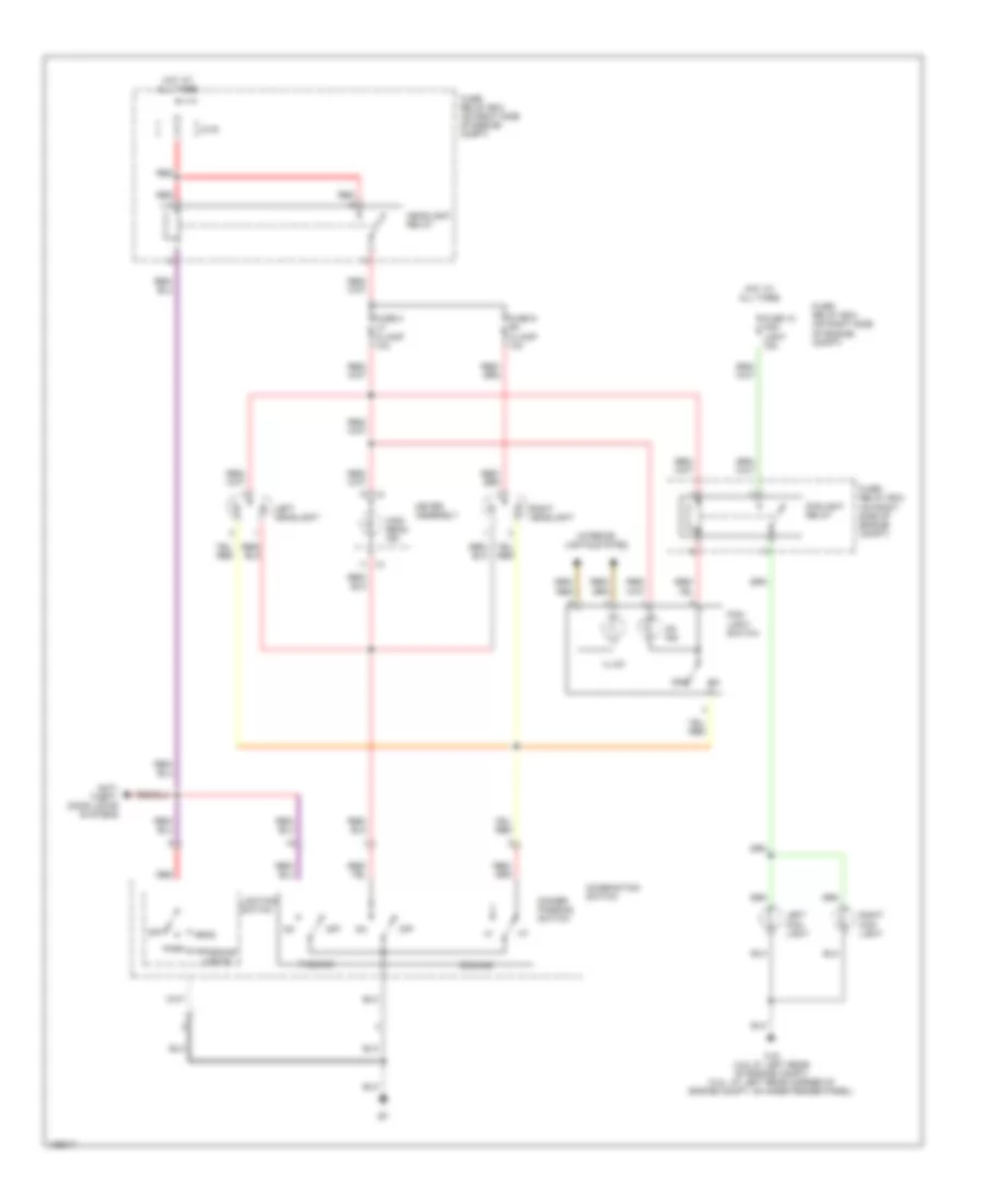
Headlights Wiring Diagram for Isuzu Rodeo S 2004
List of elements for Headlights Wiring Diagram for Isuzu Rodeo S 2004:
- Anti- theft, door locks systems
- C16 (3.5l di: left rear of engine compt) (3.2l: at left rear corner of engine compt, on inner fender panel)
- Combination switch
- Dimmer passing switch
- Dimming
- Fog- light switch
- Foglight relay
- Fuse 10 fog light 15a
- Fuse 8 lh h/lamp 10a
- Fuse 9 rh h/lamp 10a
- Fuse/ relay box (on right side of engine compt)
- Head
- Headlight relay
- High beam ind
- Hot at all times
- I-2
- Illum
- Interior lights system
- J/c b
- Left fog- light
- Left headlight
- Lighting switch
- Meter assembly
- Off
- On ind
- Park
- Parking lights
- Passing
- Red
- Right fog- light
- Right headlight
HORN
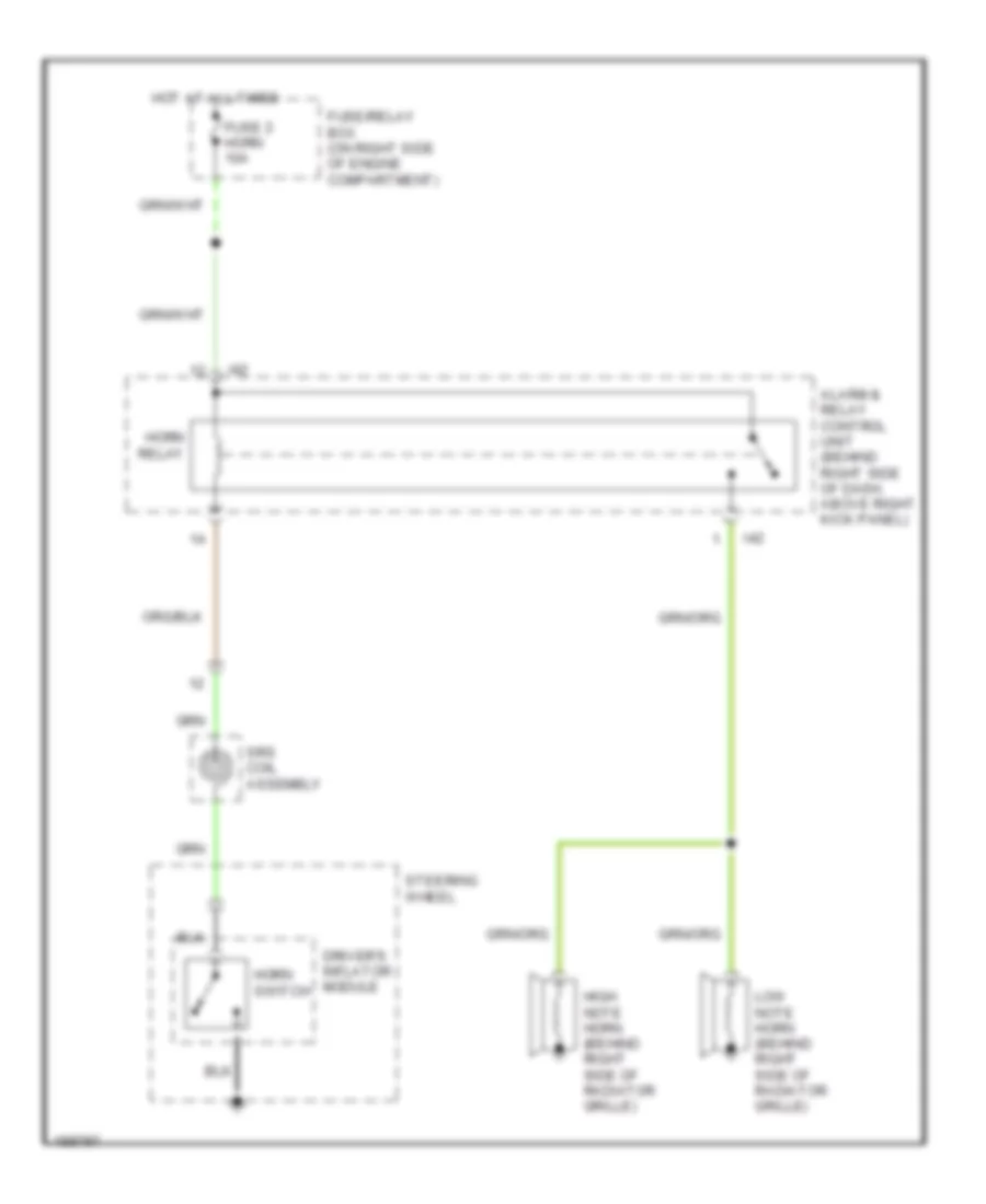
Horn Wiring Diagram for Isuzu Rodeo S 2004
List of elements for Horn Wiring Diagram for Isuzu Rodeo S 2004:
- Alarm & relay control unit (behind right side of dash, above right kick panel)
- Driver's inflator module
- Fuse 2 horn 10a
- Fuse/relay box (on right side of engine compartment)
- High note horn (behind right side of radiator grille)
- Horn relay
- Horn switch
- Hot at all times
- I42
- Low note horn (behind right side of radiator grille)
- Srs coil assembly
- Steering wheel
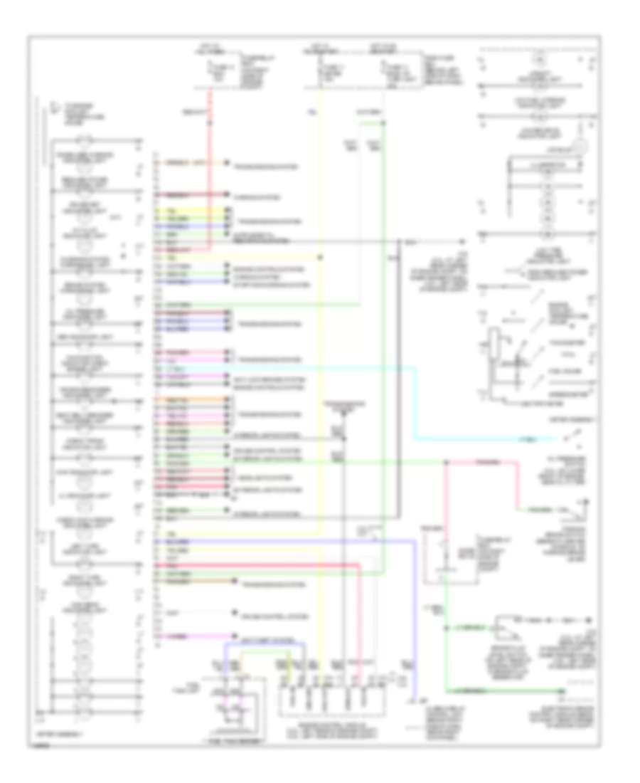
INSTRUMENT CLUSTER
Instrument Cluster Wiring Diagram for Isuzu Rodeo S 2004
List of elements for Instrument Cluster Wiring Diagram for Isuzu Rodeo S 2004:
- (a/t)
- 3.2l
- 3.2l m/t
- 3.5l
- 4l indicator light
- 4wd indicator light
- A/t fluid indicator light
- Abs indicator light
- Air bag readiness indicator light
- Alarm & relay control unit (behind right side of dash, above right kick panel)
- Anti-lock brakes system
- Anti-theft system
- Brake fluid level switch (on left rear of engine compt, in brake fluid reservoir)
- Brake system warning ind light
- C16 (3.2l: at left rear corner of engine compt, on inner fender panel) (3.5l: left rear of engine compt)
- C74
- Charging system warning ind light
- Check 4wd warning indicator light
- Check trans indicator light
- Cruise control system
- Cruise set indicator light
- Dash fuse box (behind left side of dash, behind panel)
- Diode box b
- E21
- E22
- Electronic brake control module (ebcm) (on right rear corner of engine compt)
- Engine control module (3.2l: left rear of engine compt) (3.5l: left side of engine compt)
- Engine controls system
- Engine coolant temperature gauge
- Exterior lights system
- From reduced power indicator light
- Fuel gauge
- Fuel in
- Fuel out
- Fuel tank sender
- Fuel tank unit
- Fule in
- Fuse 11 meter 15a
- Fuse 13 ecm 10a
- Fuse 14 back up/ turn light 15a
- Fuse/relay box (on right side of engine compt)
- Headlights system
- High beam indicator light
- Hot at all times
- Hot in on or start
- I42
- Illumination
- Immobilizer warning indicator light
- Interior lights system
- Lcd bulb
- Left turn indicator light
- Low fuel warning indicator light
- Low tire pressure indicator light
- Malfunction indicator check engine light
- Meter assembly
- Nca
- Odo/trip meter
- Oil pressure indicator light
- Oil pressure switch (3.2l: on lower front of engine, near oil filter)
- Parking brake switch (beneath center console, on parking brake lever)
- Pnk
- Reduced power indicator light
- Right turn indicator light
- Rpm out
- Seat belt reminder indicator light
- Sns gnd
- Speedometer
- Starting/charging system
- Tachometer
- To engine coolant temperature gauge
- Transmissions system
- Upshift indicator light
- Warning system
- Winter drive indicator light
INTERIOR LIGHTS
Courtesy Lamps Wiring Diagram for Isuzu Rodeo S 2004
List of elements for Courtesy Lamps Wiring Diagram for Isuzu Rodeo S 2004:
- Alarm & relay control unit (behind right side of dash, above right kick panel)
- Combination swtich
- Dash fuse box (behind left side of dash, behind panel)
- Dash fuse box (behind left side of dash, behind panel)
- Diode box 5
- Diode box 6
- Dome light
- Door
- Engine controls, anti-theft systems
- Exterior lights system
- Fuse 4 tail/illum light 15a
- Fuse 5 dome light 10a
- Hatch gate open switch (inside top center of tailgate, on latch assembly)
- Head
- Hot at all times
- I-42
- Keyless entry & anti-theft control unit (behind right side of dash, above kick panel)
- Left front door switch
- Left front vanity mirror light
- Left map light
- Left map light switch
- Left rear door switch
- Lighting switch
- Luggage room light
- Off
- Park
- Rear view mirror
- Red
- Right front door switch
- Right front vanity mirror light
- Right map light
- Right map light switch
- Right rear door switch
- Taillamp relay
- Wiper/washer system
Instrument Illumination Wiring Diagram for Isuzu Rodeo S 2004
List of elements for Instrument Illumination Wiring Diagram for Isuzu Rodeo S 2004:
- (2 bulbs)
- (w/ amplifier)
- (w/o amplifier)
- Ashtray light
- Combination swtich
- Cruise control main switch
- Cruise control remote switch
- Dash fuse box (behind left side of dash, behind panel)
- Drive selector switch
- Engine controls, door locks systems
- Exterior lights system
- Fog light switch
- Glove box light
- Hazard warning switch
- Head
- Heater- a/c control panel
- Hot at all times
- I-2
- Illumination controller
- Illumination controller light
- Lighting switch
- Meter assembly
- Nca
- Off
- Park
- Radio
- Radio remote switch
- Rear defogger switch
- Rear wiper switch
- Red
- Shift lock controller
- Solid state
- Srs coil assembly
- Steering wheel
- Switch unit a
- Switch unit b
- Tail/illum light fuse 4 15a
- Taillight relay
- Winter switch
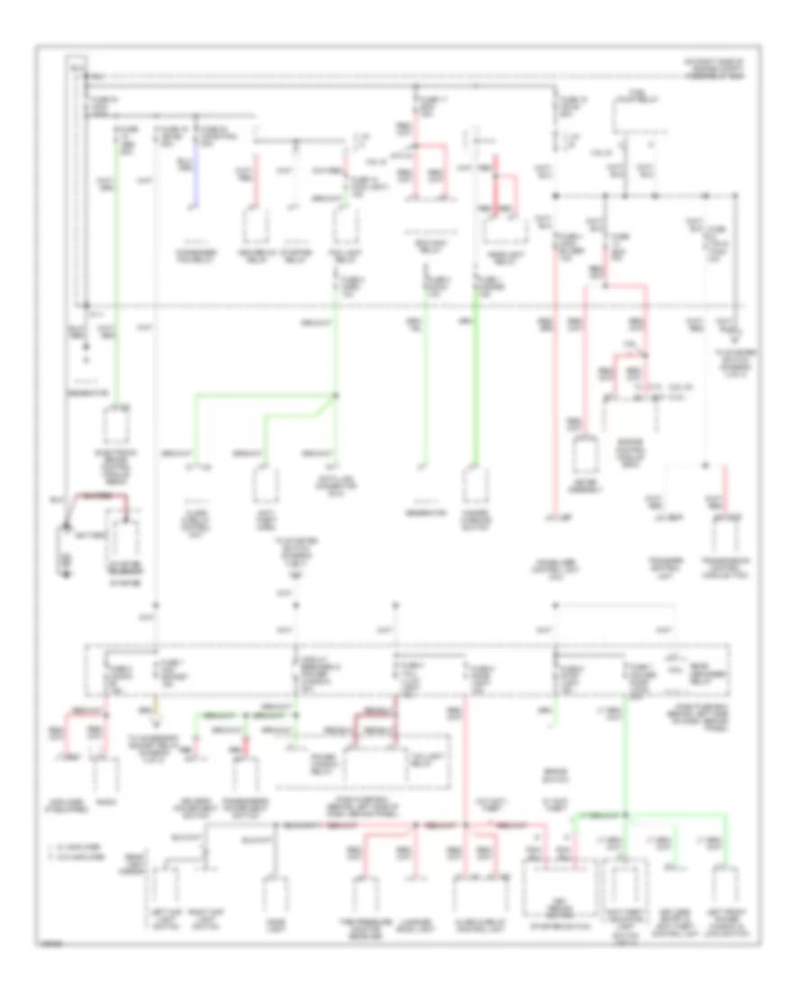
POWER DISTRIBUTION
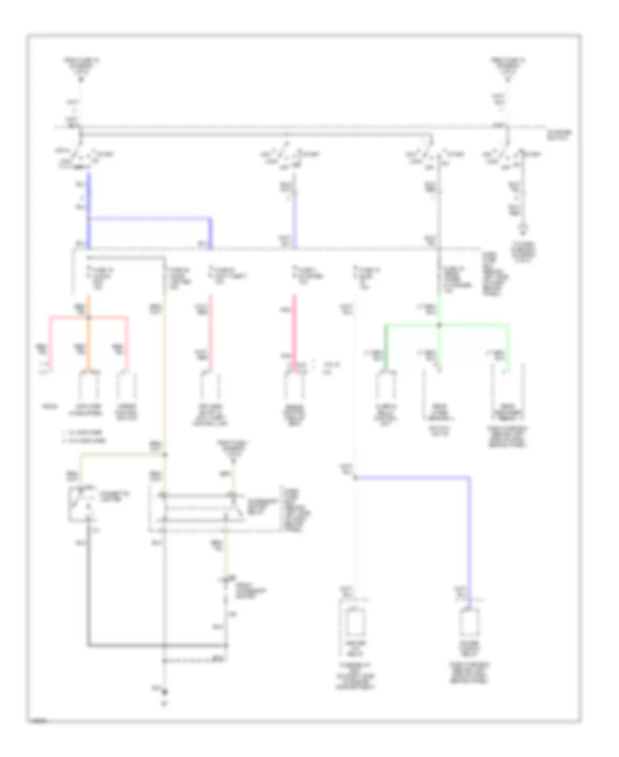
Power Distribution Wiring Diagram (1 of 3) for Isuzu Rodeo S 2004
List of elements for Power Distribution Wiring Diagram (1 of 3) for Isuzu Rodeo S 2004:
- (3.2l) e-21
- (3.5l di)
- (on right side of engine compt) fuse/relay box
- 3.2l
- 3.5l di
- Alarm & relay control unit
- Amplifier (if equipped)
- Anti- theft horn
- Anti-theft indicator light
- B-41
- B-42
- Battery
- Brake switch
- C-5
- C-74
- C-78
- Circuit breaker 21 (power window) 30a
- Coil
- Condenser fan relay
- Dash fuse box (behind left side of dash, behind panel)
- Data link connector (dlc)
- Dome light
- Driver's power seat switch
- Ecm main relay
- Electronic brake control module (ebcm)
- Engine control module (ecm)
- Fog light relay
- Fuel pump relay
- Fuse 1 acc socket 15a
- Fuse 1 hazard 15a
- Fuse 10 (fog light) 15a
- Fuse 15 ign b1 60a
- Fuse 16 main 100a
- Fuse 17 ecm 30a
- Fuse 19 ign b2 50a
- Fuse 2 (audio) b+ 15a
- Fuse 2 horn 10a
- Fuse 20 (cond fan) 30a
- Fuse 3 acg-5 10a
- Fuse 4 immo- bilizer 10a
- Fuse 4 tail/ illum light 15a
- Fuse 5 dome light 10a
- Fuse 6 stop light 15a
- Fuse 7 (power door lock) 20a
- Fuse abs 50a
- Fuse ecm 10a
- Generator
- Hazard warning switch
- Headlight relay
- Heater-a/c relay
- I-1
- I-41
- I-42
- I-55
- Immobilizer control unit (icu)
- J/c a
- J/c b
- Key remind switch
- Keyless entry & anti-theft control unit
- Left front power window & lock switch
- Left map light switch
- Luggage room light
- Meter assembly
- P-11
- P-2
- Passenger's power seat switch
- Power window relay
- Radio
- Rear defogger relay
- Rear view mirror
- Red
- Right map light switch
- Starter
- Starter relay
- Starter solenoid
- Starter switch
- Switch unit a
- Taillight relay
- Tire pressure monitor receiver
- To accessory socket relay (diagram 2 of 3)
- To starter switch (diagram 2 of 3)
- Transfer control unit
- Transmission control module (tcm)
- W/ amplifier
- W/ anti- theft
- W/o amplifier
- W/o anti- theft
Power Distribution Wiring Diagram (2 of 3) for Isuzu Rodeo S 2004
List of elements for Power Distribution Wiring Diagram (2 of 3) for Isuzu Rodeo S 2004:
- (if equipped)
- 3.2l
- 3.5l di
- Acc
- Accessory socket relay
- Alarm & relay control unit
- Amplifier
- B-41
- C-74
- Cigarette lighter
- Dash fuse box (behind left side of dash, behind panel)
- E-21
- Engine control module (ecm)
- From fuse 1 (diagram 1 of 3)
- From fuse 15 (diagram 1 of 3)
- From fuse 19 (diagram 1 of 3)
- Front accessory socket
- Fuse 15 elec ig 10a
- Fuse 16 (rear wiper & washer) 10a
- Fuse 19 (audio) acc 10a
- Fuse 20 cigar lighter 15a
- Fuse 23 (anti-theft) 10a
- Fuse 3 starter 10a
- Fuse/relay box (on right side of engine compartment)
- Heater a/c relay
- I-21
- I-22
- I-28
- I-29
- I-41
- Keyless entry & anti-theft control unit
- Lock
- Mirror control switch
- Off
- Pnk
- Power window relay
- Radio
- Rear defogger relay
- Rear wiper switch
- Start
- Starter switch
- Switch unit b
- To dash fuse box (diagram 3 of 3)
- W/ amplifier
- W/o amplifier
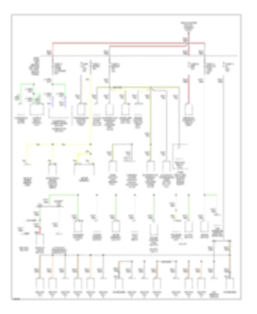
Power Distribution Wiring Diagram (3 of 3) for Isuzu Rodeo S 2004
List of elements for Power Distribution Wiring Diagram (3 of 3) for Isuzu Rodeo S 2004:
- (3.2l)
- (3.5l)
- 3.2l
- 3.2l m/t
- 3.5l
- A1 c4
- Alarm & relay control unit
- Automatic transmission mode switch
- Automatic transmission mode switch (3.2l a/t, 3.5l)
- B-19
- Back-up lights switch
- Brake switch
- C-74
- C-78
- Clutch start switch (3.2l m/t)
- Clutch switch
- Combination switch
- Condenser
- Cruise control main switch
- Dash fuse box (behind left side of dash, behind panel)
- E-64
- Ecm main relay (3.2l)
- Electronic brake control module (ebcm)
- Engine control module (ecm) (3.5l)
- Evaporative emission (evap) canister purge valve
- Evaporative emissions (evap) canister vent valve
- Except 3.2l m/t
- From starter switch (diagram 2 of 3)
- Fuse 11 meter 15a
- Fuse 12 engine ign 15a
- Fuse 13 ig coil 15a
- Fuse 14 back-up/ turn light 15a
- Fuse 17 front wiper & washer 20a
- Fuse 22 srs 10a
- Fuse tcm 15a
- Fuse/ relay box (on right side of engine compt)
- Hazard warning switch
- I-1
- I-55
- I-9
- Ignition coil
- Immobilizer control unit (icu)
- Ion sensing module
- Mass air flow (maf) sensor (3.2l)
- Meter assembly
- Meter assembly (3.2l m/t)
- Neutral switch
- Red
- Sensing & diagnostic module (sdm)
- Shift lock relay
- Switch unit a
- Tire pressure monitor receiver
- Transfer control unit
- Transmission control module (tcm)
- Variable intake manifold vacuum switching valve
- Vehicle speed sensor (vss)
- Windshield wiper motor
- Windshield wiper/washer switch
POWER DOOR LOCKS
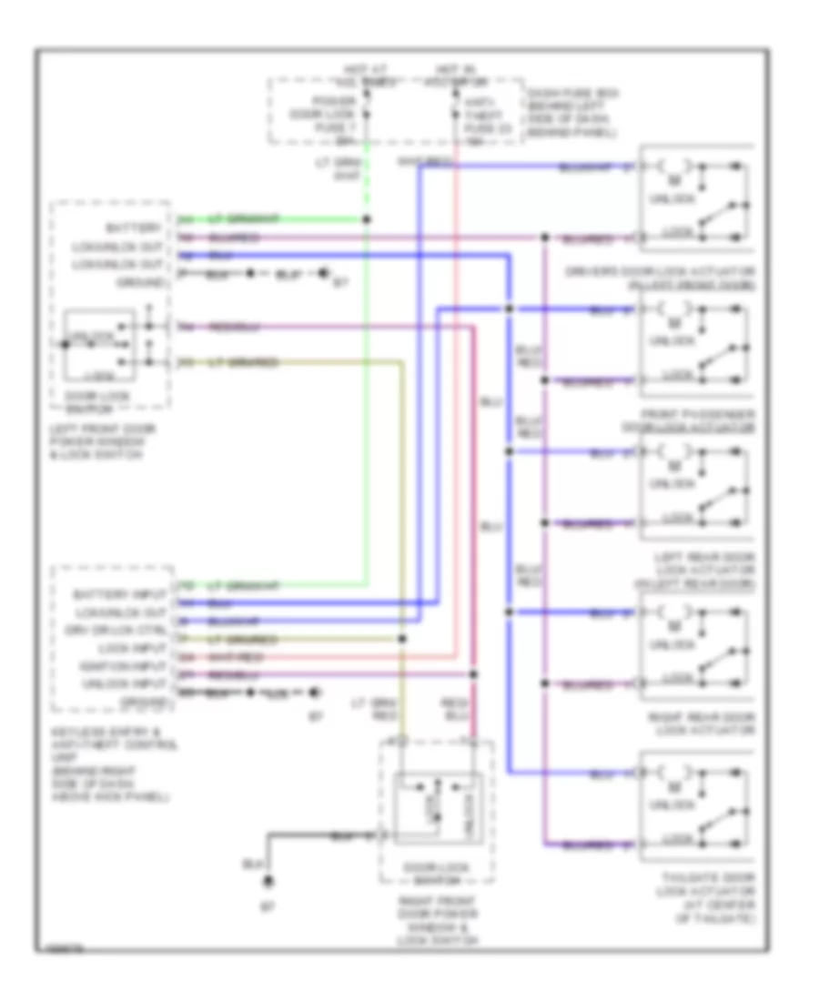
Power Door Locks Wiring Diagram, with Keyless Entry for Isuzu Rodeo S 2004
List of elements for Power Door Locks Wiring Diagram, with Keyless Entry for Isuzu Rodeo S 2004:
- Anti- theft fuse 23 10a
- Battery
- Battery input
- Dash fuse box (behind left side of dash, behind panel)
- Door lock switch
- Driver's door lock actuator (in left front door)
- Drv dr lck ctrl
- Front passenger door lock actuator
- Ground
- Hot at all times
- Hot in acc or on
- Ignition input
- Keyless entry & anti-theft control unit (behind right side of dash, above kick panel)
- Lck/unlck out
- Left front door power window & lock switch
- Left rear door lock actuator (in left rear door)
- Lock
- Lock input
- Power door lock fuse 7 20a
- Right front door power window & lock switch
- Right rear door lock actuator
- Tailgate door lock actuator (at center of tailgate)
- Unlock
- Unlock input
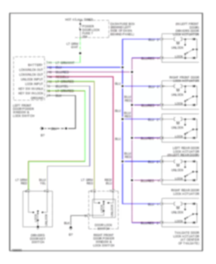
Power Door Locks Wiring Diagram, without Keyless Entry for Isuzu Rodeo S 2004
List of elements for Power Door Locks Wiring Diagram, without Keyless Entry for Isuzu Rodeo S 2004:
- (in left front door) driver's door lock actuator
- Battery
- Dash fuse box (behind left side of dash, behind panel)
- Door lock switch
- Driver's door key switch
- Ground
- Hot at all times
- Key sw in lock
- Key sw in unlk
- Lck/unlck out
- Left front door power window & lock switch
- Left rear door lock actuator (in left rear door)
- Lock
- Lock input
- Power door lock fuse 7 20a
- Right front door lock actuator
- Right front door power window & lock switch
- Right rear door lock actuator
- Tailgate door lock actuator (at center of tailgate)
- Unlock
- Unlock input
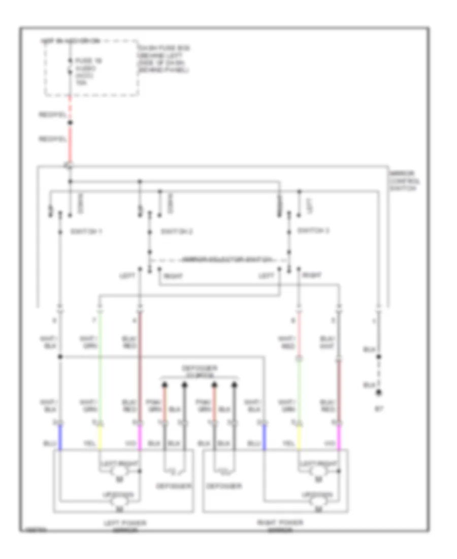
POWER MIRRORS
Power Mirrors Wiring Diagram for Isuzu Rodeo S 2004
List of elements for Power Mirrors Wiring Diagram for Isuzu Rodeo S 2004:
- Dash fuse box (behind left side of dash, behind panel)
- Defogger
- Defogger system
- Down
- Fuse 18 audio (acc) 10a
- Hot in acc or on
- Left
- Left power mirror
- Left/right
- Mirror control switch
- Mirror selector switch
- Right
- Right power mirror
- Switch 1
- Switch 2
- Switch 3
- Up/down
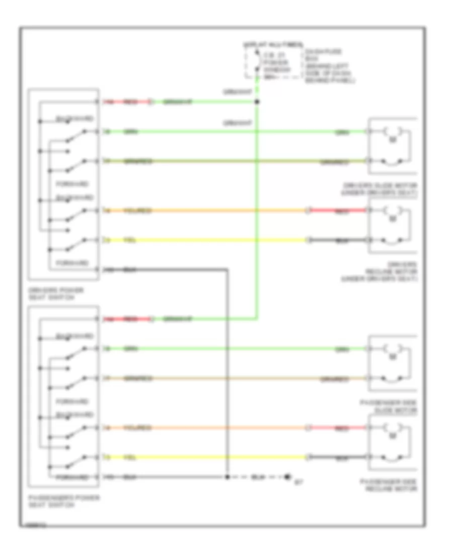
POWER SEATS
Power Seats Wiring Diagram for Isuzu Rodeo S 2004
List of elements for Power Seats Wiring Diagram for Isuzu Rodeo S 2004:
- Backward
- C.b. 21 power window 30a
- Dash fuse box (behind left side of dash, behind panel)
- Driver's power seat switch
- Driver's recline motor (under driver's seat)
- Driver's slide motor (under driver's seat)
- Forward
- Hot at all times
- Passenger side recline motor
- Passenger side slide motor
- Passenger's power seat switch
- Red
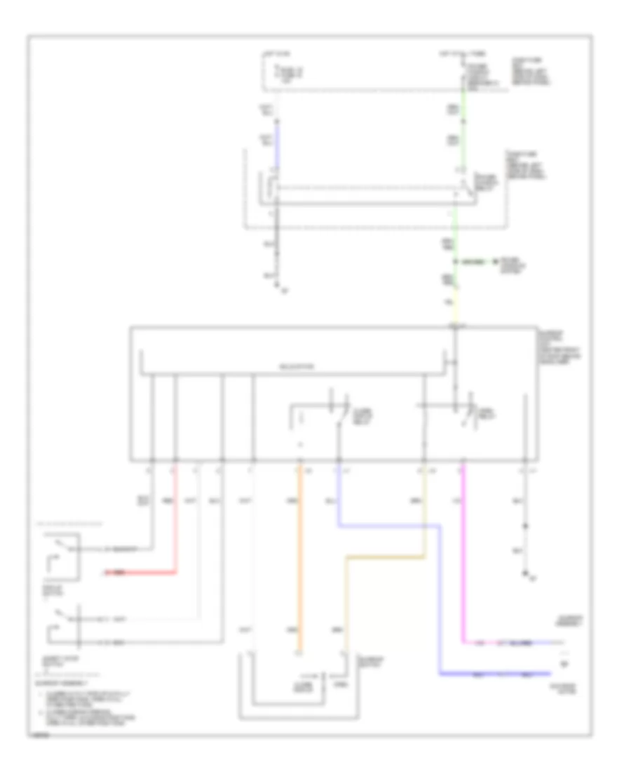
POWER TOP/SUNROOF
Power Top/Sunroof Wiring Diagram for Isuzu Rodeo S 2004
List of elements for Power Top/Sunroof Wiring Diagram for Isuzu Rodeo S 2004:
- Close/ pop-up
- Close/ pop-up relay
- Closed during opening,
- Closed in tilt (pop-up) & fully
- Dash fuse box (behind left side of dash, behind panel)
- Elec. ig fuse 15 10a
- Fully open, & closing positions. open in all other positions.
- Hot at all times
- Hot in on
- J-1
- J-2
- Open
- Open positions. open in all other positions
- Open relay
- Pop-up switch
- Power window circuit breaker 21 30a
- Power window relay
- Power windows system
- Red
- Safety stop switch
- Solid state
- Sun roof motor
- Sunroof assembly
- Sunroof control unit (center front of roof behind headliner)
- Sunroof switch
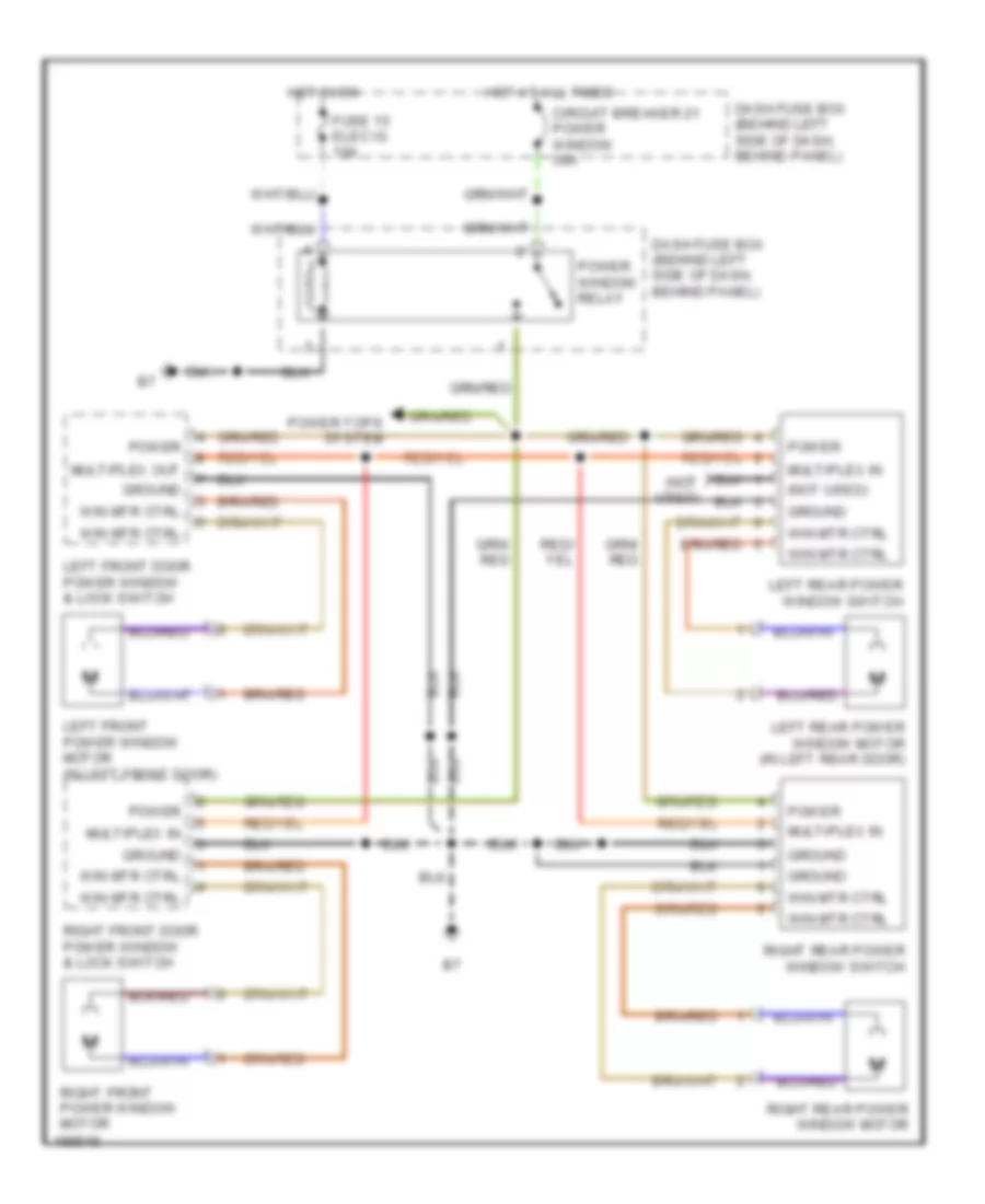
POWER WINDOWS
Power Windows Wiring Diagram for Isuzu Rodeo S 2004
List of elements for Power Windows Wiring Diagram for Isuzu Rodeo S 2004:
- (not used)
- Circuit breaker 21 power window 30a
- Dash fuse box (behind left side of dash, behind panel)
- Fuse 15 elec ig 10a
- Ground
- Hot at all times
- Hot in on
- Left front door power window & lock switch
- Left front power window motor (in left front door)
- Left rear power window motor (in left rear door)
- Left rear power window switch
- Multiplex in
- Multiplex out
- Power
- Power tops system
- Power window relay
- Right front door power window & lock switch
- Right front power window motor
- Right rear power window motor
- Right rear power window switch
- Win mtr ctrl
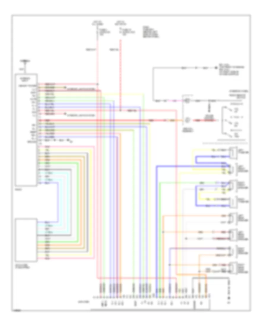
RADIO
Radio Wiring Diagram, with Amplifier for Isuzu Rodeo S 2004
List of elements for Radio Wiring Diagram, with Amplifier for Isuzu Rodeo S 2004:
- (3.2l)
- (3.5l)
- Acc
- Amp +
- Amp+
- Amplifier
- Antenna
- Antenna input
- B40
- B41
- Beep
- Cd player (if equipped)
- Ch/ trk
- Cruise control system
- Dash fuse box (behind left side of dash, behind panel)
- E21 (top front of engine) e30 (at right side of intake manifold)
- Fl +
- Fl -
- Fr +
- Fr -
- Fuse 19 (audio) acc 10a
- Fuse 2 (audio) b+ 15a
- Ground
- Hot at all times
- Hot in acc or on
- I15
- Ill+
- Ill-
- Interior lights system
- Left front speaker
- Left rear door speaker
- Left rear speaker
- Left tweeter
- Memory power
- Mute
- Nca
- Pnk
- Radio
- Radio remote switch
- Red
- Right front speaker
- Right rear door speaker
- Right rear speaker
- Right tweeter
- Rl +
- Rl -
- Rr +
- Rr -
- Srs coil assembly
- Steering wheel
- Vol dn
- Vol up
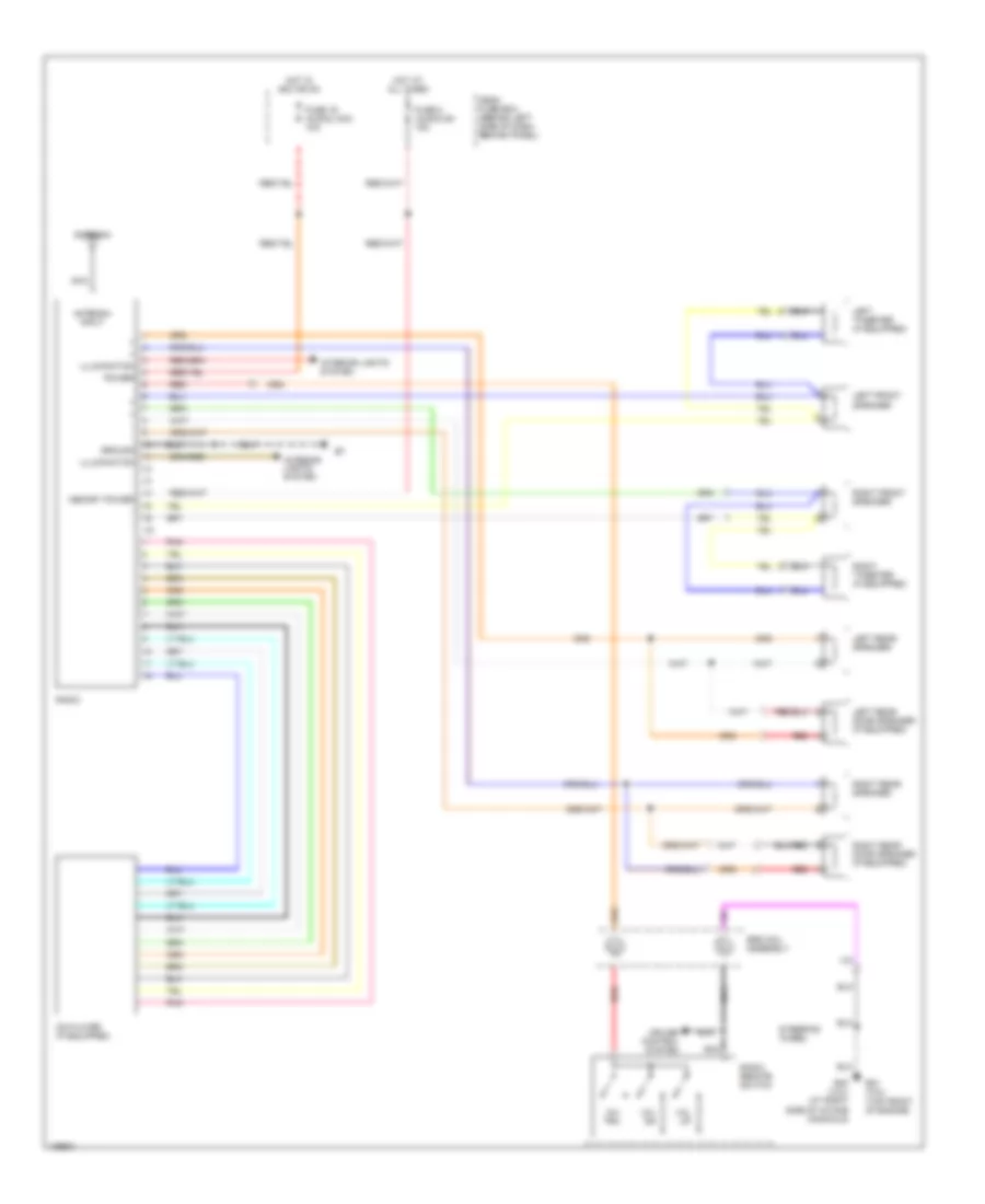
Radio Wiring Diagram, without Amplifier for Isuzu Rodeo S 2004
List of elements for Radio Wiring Diagram, without Amplifier for Isuzu Rodeo S 2004:
- Antenna
- Antenna input
- Cd player (if equipped)
- Ch/ trk
- Cruise control system
- Dash fuse box (behind left side of dash, behind panel)
- E21 (3.5l) (top front of engine)
- E30 (3.2l) (at right side of intake manifold)
- Fuse 19 (audio) acc 10a
- Fuse 2 (audio) b+ 15a
- Ground
- Hot at all times
- Hot in acc or on
- I15
- Illumination
- Interior lights system
- Left front speaker
- Left rear door speaker (if equipped)
- Left rear speaker
- Left tweeter (if equipped)
- Memory power
- Nca
- Pnk
- Power
- Radio
- Radio remote switch
- Red
- Right front speaker
- Right rear door speaker (if equipped)
- Right rear speaker
- Right tweeter (if equipped)
- Srs coil assembly
- Steering wheel
- Vol dn
- Vol up
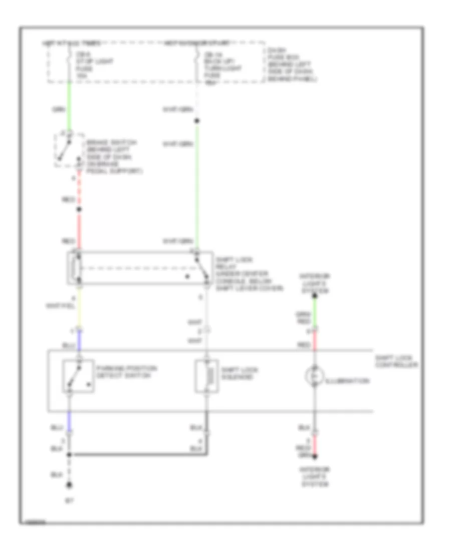
SHIFT INTERLOCK
Shift Interlock Wiring Diagram for Isuzu Rodeo S 2004
List of elements for Shift Interlock Wiring Diagram for Isuzu Rodeo S 2004:
- Brake switch (behind left side of dash, on brake pedal support)
- Cb-14 back up/ turn light fuse 15a
- Cb-6 stop light fuse 15a
- Dash fuse box (behind left side of dash, behind panel)
- Hot at all times
- Hot in on or start
- Illumination
- Interior lights system
- Parking position detect switch
- Red
- Shift lock controller
- Shift lock relay (under center console, below shift lever cover)
- Shift lock solenoid
STARTING/CHARGING
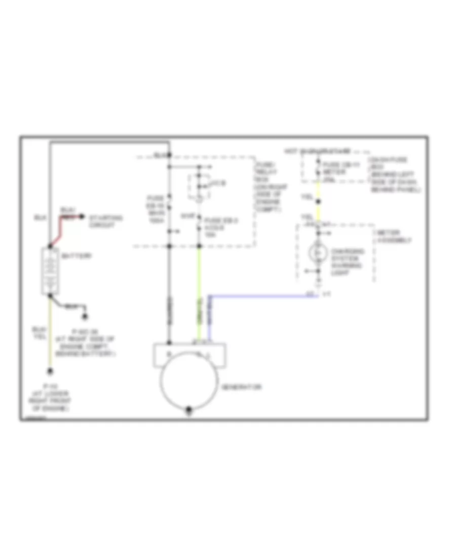
Charging Wiring Diagram for Isuzu Rodeo S 2004
List of elements for Charging Wiring Diagram for Isuzu Rodeo S 2004:
- Battery
- Charging system warning light
- Dash fuse box (behind left side of dash, behind panel)
- Fuse cb-11 meter 15a
- Fuse eb-16 main 100a
- Fuse eb-3 acg-s 10a
- Fuse/ relay box (on right side of engine compt)
- Generator
- Hot in on or start
- I-1
- J/c b
- Meter assembly
- P-10 (at lower right front of engine)
- P-6/c-36 (at right side of engine compt, behind battery)
- Starting circuit
Starting Wiring Diagram for Isuzu Rodeo S 2004
List of elements for Starting Wiring Diagram for Isuzu Rodeo S 2004:
- 3.2l
- 3.5l
- A/t
- Acc
- Automatic transmission mode switch (3.2l: right side of transmission) (3.5l: on right side of transmission)
- Battery
- C-74
- Clutch start switch (behind left side of dash, on clutch pedal support)
- Dash fuse box (behind left side of dash, behind panel)
- E-21
- E-22
- Engine control module (ecm) (3.2l: left rear of engine compt) (3.5l di: left side of engine compt)
- Fuse cb-12 engine ig 15a
- Fuse cb-3 starter 10a
- Fuse eb-16 main 100a
- Fuse eb-19 ign-b2 50a
- Fuse/ relay box (on right side of engine compt)
- Fuse/relay box (on right side of engine compt)
- Hoid- in coil
- Hot in on or start
- J/c a
- Lock
- M/t
- Off
- P10 (at lower right front of engine)
- P6/c36 (at right side of engine compt, behind battery)
- Pnk
- Pull-in coil
- Rly ctrl
- Start
- Starter
- Starter motor
- Starter relay
- Starter solenoid
- Starter switch
- Str feed
SUPPLEMENTAL RESTRAINTS
Supplemental Restraints Wiring Diagram for Isuzu Rodeo S 2004
List of elements for Supplemental Restraints Wiring Diagram for Isuzu Rodeo S 2004:
- (below center console)
- Air bag readiness indicator light
- Cb-11 meter fuse 15a
- Cb-22 srs fuse 10a
- Dash fuse box (behind left side of dash, behind panel)
- Data link connector (dlc) (partial) (below left side of dash, near engine hood release)
- Dlc output
- Driver's inflator module
- Driver's seat belt buckled input
- Driver's seat belt switch (open w/ seat belt buckled)
- Engine controls system
- Gnd
- High
- Hot in on or start
- I-1
- I43 (below left side of dash, above kick panel)
- Ignition
- Indicator
- Low
- Meter assembly
- Passenger's inflator module
- Red
- Sensing & diagnostic module (below center of dash)
- Serial data
- Srs coil assembly
- Steering wheel
- Warning system
TRANSMISSION
4WD Wiring Diagram, Shift on the Fly for Isuzu Rodeo S 2004
List of elements for 4WD Wiring Diagram, Shift on the Fly for Isuzu Rodeo S 2004:
- (3.2l) (at right side
- (3.5l: left rear of engine compartment) (3.2l: at left rear corner of engine compartment, on inner fender panel) c16
- (a/t)
- (at right side of intake manifold) (m/t) e30
- (m/t)
- (on right rear corner of engine compartment) electronic brake control module (ebcm)
- (under left side of dash) transmission control module
- 2-4wd switch
- 2h sw
- 4h ind
- 4h sw
- 4l ind
- 4l ind light
- 4l sw
- 4l-out
- 4l-signal
- 4wd engage
- 4wd ind light
- 4wd sig
- 4wd sw
- A/t circuit
- Automatic transmission mode switch (on right side of transmission)
- Axl-m1
- Axl-m2
- Axle sw
- B-19
- B-42
- Battery
- Brakes system
- C-4
- C-79
- C16 (3.5l: left rear of engine compartment) (3.2l: at left rear corner of engine compartment, on inner fender panel)
- Check 4wd warning light
- Check ind
- Dash fuse box (behind left side of dash, behind panel)
- Drive selector switch
- E30 e21 (3.5l) (top front of of intake manifold)
- Engine)
- Front axle motor actuator (on left side of front axle)
- Fuse 11 meter 15a
- Fuse 14 back up/ turn light 15a
- Fuse 14 tcm & tccm 10a
- Fuse/ relay box (on right side of engine compt)
- Gnd
- Ground
- Hot at all times
- Hot in on or start
- I-1
- I-2
- Ignition
- Interior lights system
- Limit sw1
- Limit sw2
- Limit sw3
- Limit sw4
- Ls1-sw
- Ls2-sw
- Ls3-sw
- Ls4-sw
- M/t
- Meter assembly
- N sw
- Neutral switch
- Neutral switch (m/t)
- Red
- Shift motor
- T/f-m1
- T/f-m2
- T/m 1-sw
- Tach sig
- Transfer actuator (a/t: on rear of transmission) (m/t: beneath center of vehicle, on transfer case)
- Transfer control unit (below center console)
- Vehicle speed sensor (m/t) (m/t: on rear of transmission) (a/t: underside of vehicle, on transmission)
- Vss sig
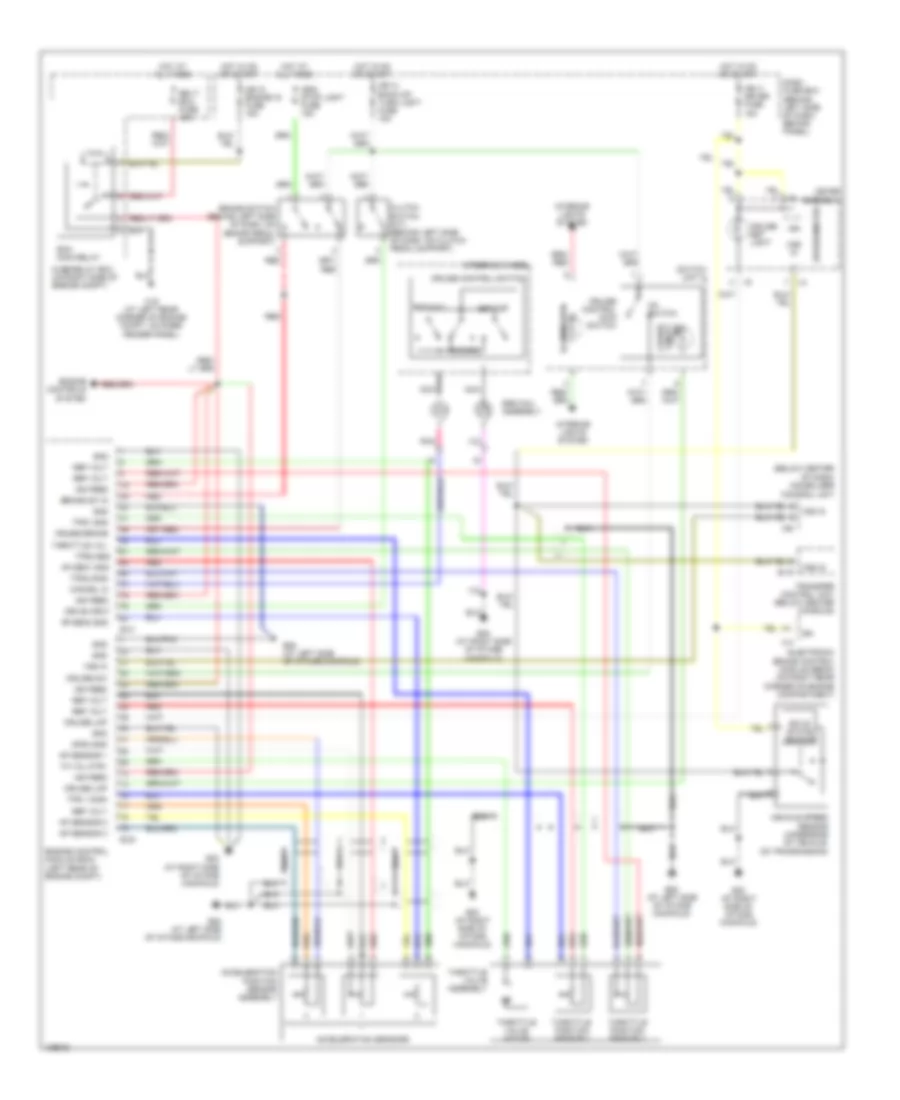
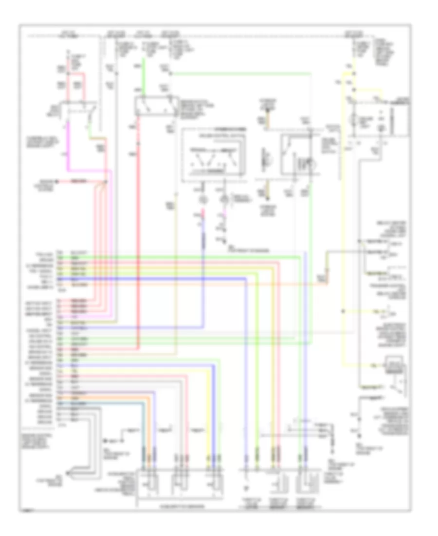
A/T Wiring Diagram for Isuzu Rodeo S 2004
List of elements for A/T Wiring Diagram for Isuzu Rodeo S 2004:
- (3.2l)
- (3.2l) (3.5l)
- (3.5l)
- (3.5l: top front of engine) (3.2l: at right side of intake manifold)
- (on right side of transmission) automatic transmission mode switch
- (right side of transmission)
- (under left side of dash) transmission control module
- 3.2l
- 3.5l
- 4l-signal
- A/t fluid ind light
- A/t oil ind
- Alarm & relay control unit (behind right side of dash, above right kick panel)
- Automatic transmission
- B-19
- B-42
- Battery
- Brake
- Brake switch (behind left side of dash, on brake pedal support)
- C-74
- C-78
- C-79
- Can+
- Can-
- Check trans ind light
- Chk tran ind
- Cruise control system
- Dash fuse box (behind left side of dash, behind panel)
- Data link connector (dlc) (below left side of dash, near engine hood release)
- Dgi
- E-22
- E30 e21
- Engine control module (3.2l: left rear of engine compt) (3.5l: left side of engine compt)
- Exterior lights system
- Fuse 11 meter 15a
- Fuse 14 back up/ turn light 15a
- Fuse 14 tcm & tccm 10a
- Fuse 18 tcm 15a
- Fuse 6 stop light 15a
- Fuse/ relay box (on right side of engine compt)
- Ground
- Hot at all times
- Hot in on or start
- I-1
- I-2
- I-42
- I-9
- Ignition
- Input revolution sensor (3.5: dinear left front exhaust downpipe) (3.2l: left side of transmission)
- Interior lights system
- J1850
- Meter assembly
- Nco
- Ncog
- Oil temp sensor 1
- Ot1
- Ot1g
- Ot2
- Ot2g
- Output revolution sensor (on right side of automatic transmission)
- Pnk
- Pressure control solenoid
- Red
- Shift indicator
- Sl/slu
- Slug
- Solenoids
- Sp2
- Sp2g
- Sth
- Sthg
- Transfer control unit (below center console)
- Transmission oil temp sensor
- Winter
- Winter drive ind light
- Winter ind
- Winter sw
- Winter switch
WARNING SYSTEMS
Chime Wiring Diagram for Isuzu Rodeo S 2004
List of elements for Chime Wiring Diagram for Isuzu Rodeo S 2004:
- Alarm & relay control unit (behind right side of dash, above right kick panel)
- Anti-theft system
- Battery
- Beeper
- Combination switch
- Dash fuse box (behind left side of dash, behind panel)
- Driver's seat belt switch
- Drvr's door open input
- Fuse 2 horn 10a
- Fuse 4 tail/illum light 15a
- Fuse 5 dome light 10a
- Fuse 7 (power door lock) 20a
- Fuse meter 15a
- Fuse/ relay box (on right side of engine compt)
- Ground
- Head
- Hot at all times
- Hot in on or start
- I-1
- I-41
- I-42
- Interior lights system
- Interior lights, anti-theft systems
- Key in ign input
- Key reminder switch
- Left front door switch (at left front door striker)
- Lighting switch
- Lights on input
- Meter assembly
- Off
- Park
- Red
- Seat belt reminder light
- Starter switch
- Tail light relay
- W/ anti-theft
- W/o anti-theft
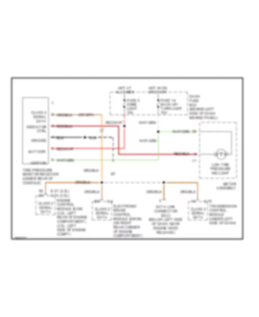
Tire Pressure Monitoring Wiring Diagram for Isuzu Rodeo S 2004
List of elements for Tire Pressure Monitoring Wiring Diagram for Isuzu Rodeo S 2004:
- Battery
- C-4
- C-79
- Class 2 serial data
- Dash fuse box (behind left side of dash, behind panel)
- Data link connector (dlc) (below left side of dash, near engine hood release)
- E-21 (3.2l) (3.5l) c-74
- Electronic brake control module (ebcm) (on right rear corner of engine compartment)
- Engine control module (ecm) (3.2l: left rear of engine compartment) (3.5l: left side of engine compt)
- Fuse 14 back up/ turn light 15a
- Fuse 5 dome light 10a
- Ground
- Hot at all times
- Hot in on or start
- I-1
- Ignition
- Indicator ctrl
- Low tire pressure ind light
- Meter assembly
- Tire pressure monitor receiver (under rear of console)
- Transmission control module (under left side of dash)
WIPER/WASHER
Front Wiper/Washer Wiring Diagram for Isuzu Rodeo S 2004
List of elements for Front Wiper/Washer Wiring Diagram for Isuzu Rodeo S 2004:
- Alarm & relay control unit (behind right side of dash, above right kick panel)
- C36/p6 (at right side of engine compt, behind battery)
- Combination switch
- Dash fuse box (behind left side of dash, behind panel)
- Front wiper & washer fuse 17 20a
- Gnd
- Hot in on or start
- I-41
- I-42
- Ignition
- Int
- Int input
- Off
- Off input
- Park
- Ref
- Run
- Run/park in
- Var int input
- Variable intermittent
- W/ variable intermittent wipers
- Wash
- Wash input
- Windshield washer motor (on right front of engine compartment, in washer fluid reservoir)
- Windshield wiper motor (on right rear corner of engine compartment, on firewall)
- Windshield wiper/washer switch
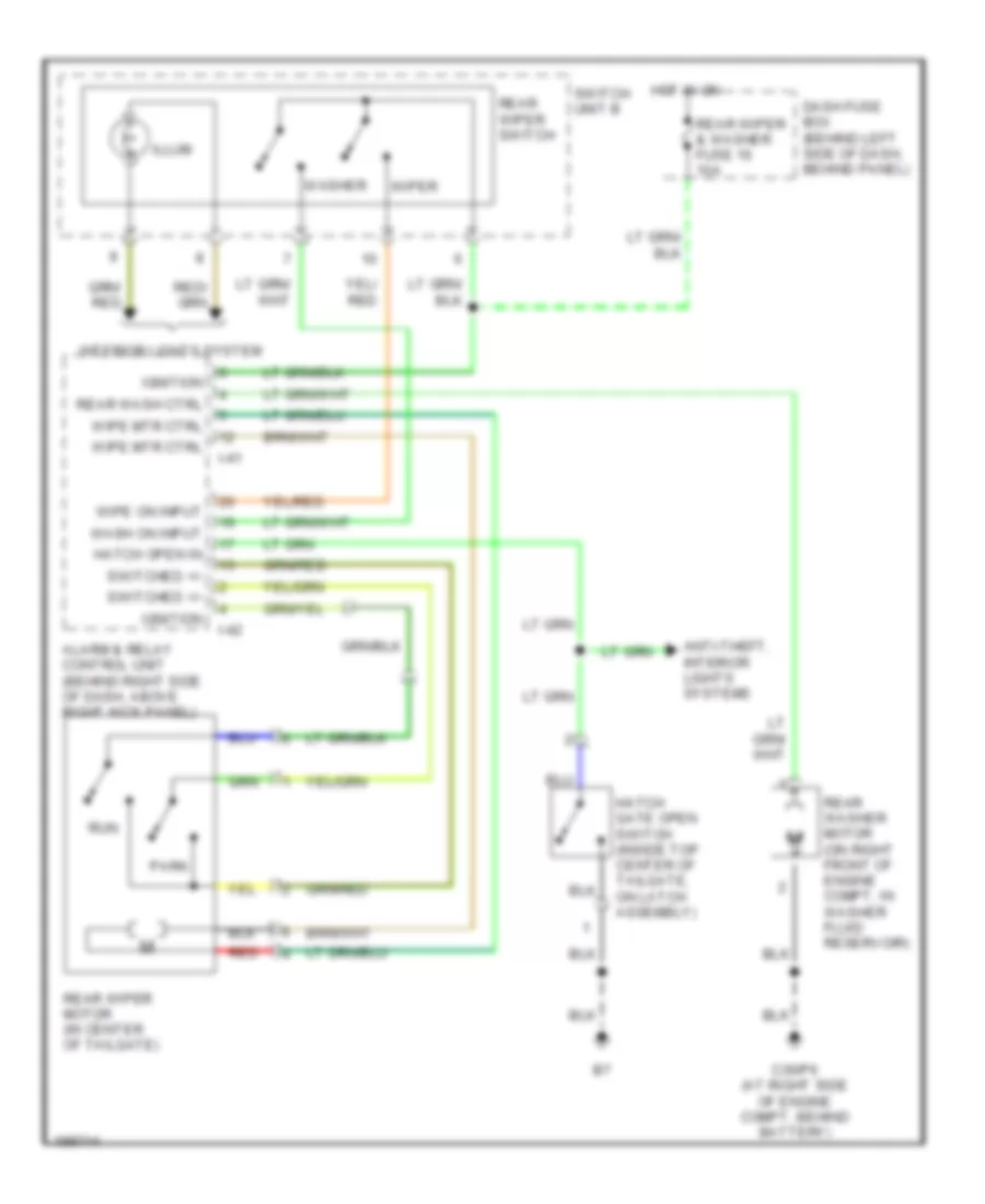
Rear Wiper/Washer Wiring Diagram for Isuzu Rodeo S 2004
List of elements for Rear Wiper/Washer Wiring Diagram for Isuzu Rodeo S 2004:
- Alarm & relay control unit (behind right side of dash, above right kick panel)
- Anti-theft, interior lights systems
- C36/p6 (at right side of engine compt, behind battery)
- Dash fuse box (behind left side of dash, behind panel)
- Hatch gate open switch (inside top center of tailgate, on latch assembly)
- Hatch open in
- Hot in on
- I-41
- I-42
- Ignition
- Illum
- Interior lights system
- Park
- Rear wash ctrl
- Rear washer motor (on right front of engine compt, in washer fluid reservoir)
- Rear wiper & washer fuse 16 10a
- Rear wiper motor (in center of tailgate)
- Rear wiper switch
- Red
- Run
- Switch unit b
- Switched +/-
- Wash on input
- Washer
- Wipe mtr ctrl
- Wipe on input
- Wiper