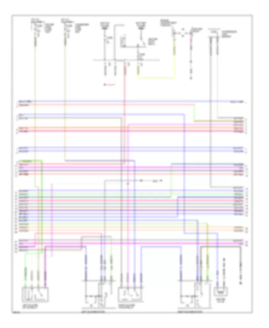
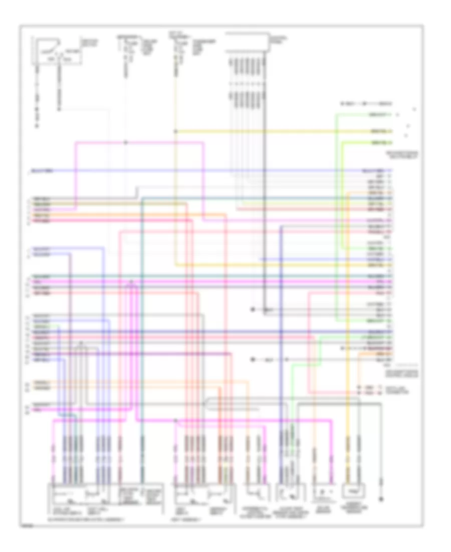
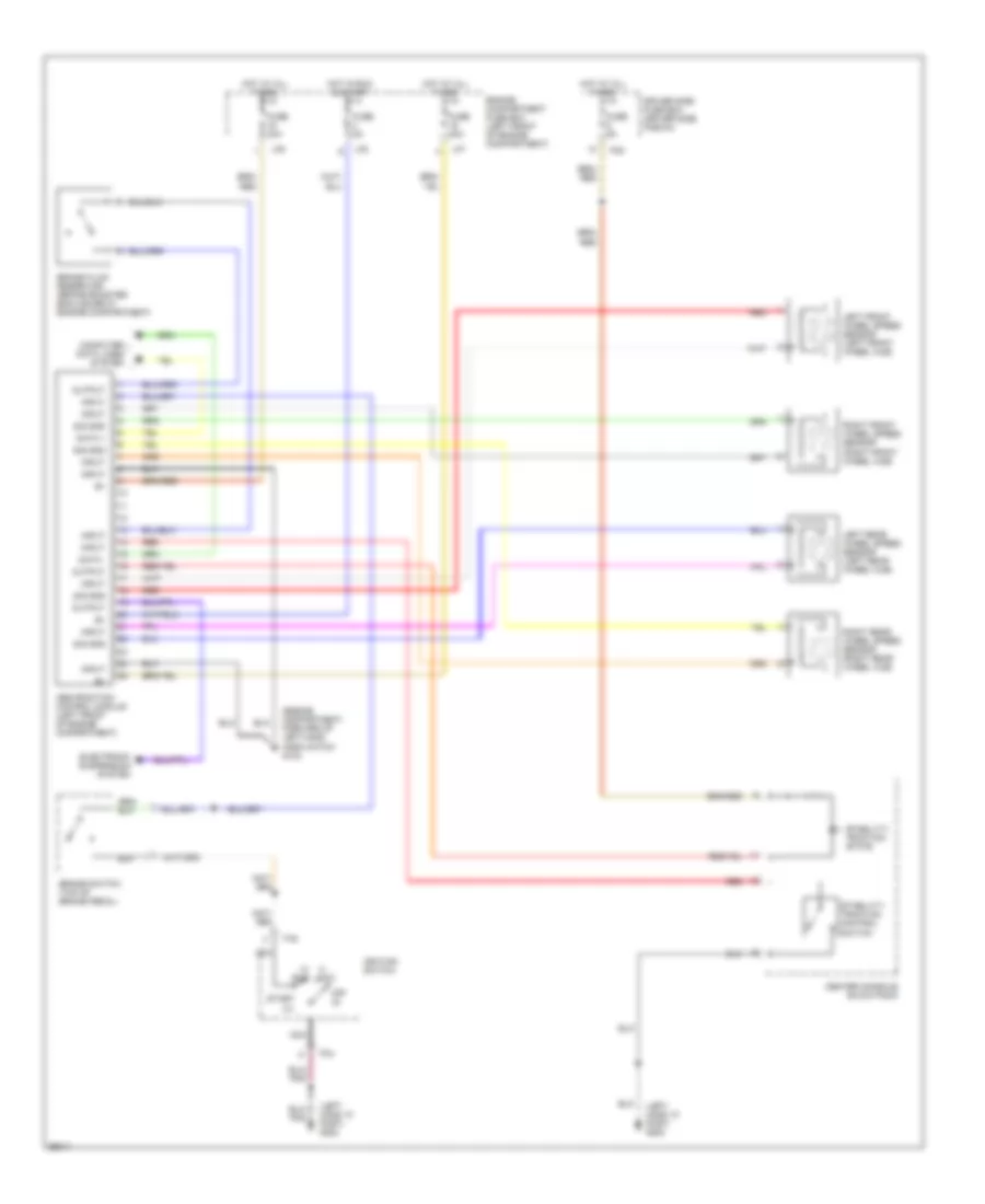
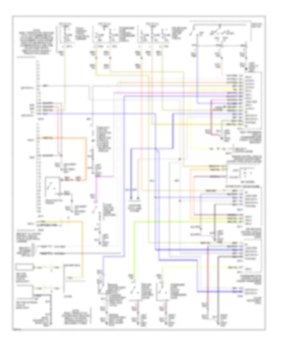
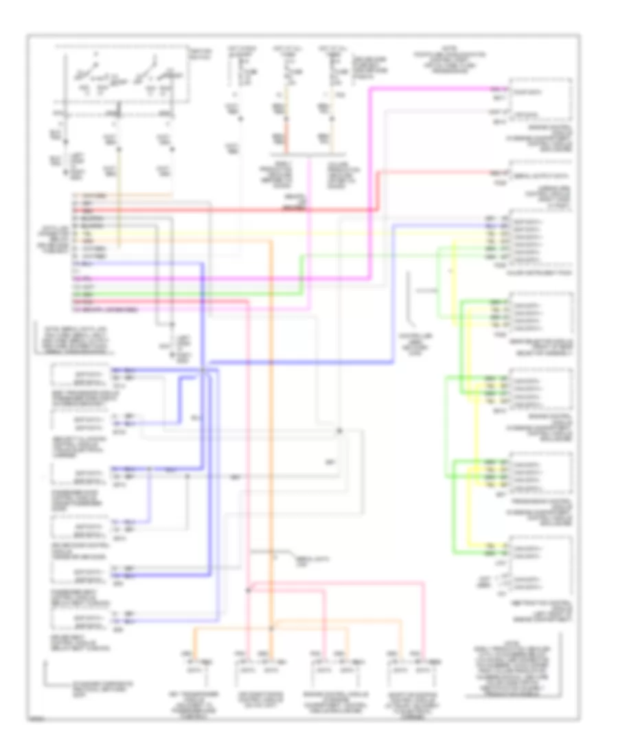
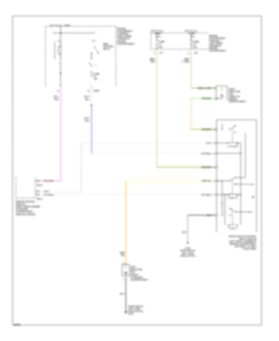
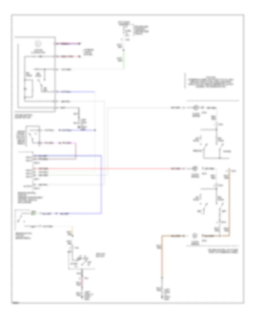
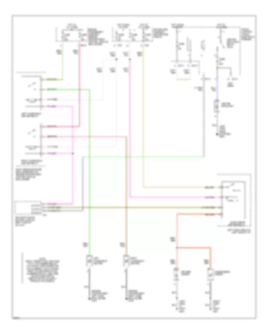
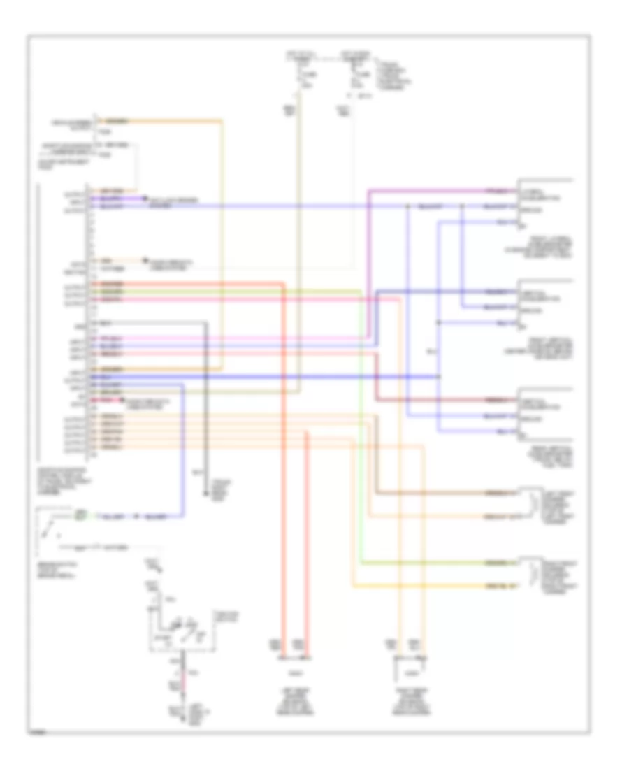
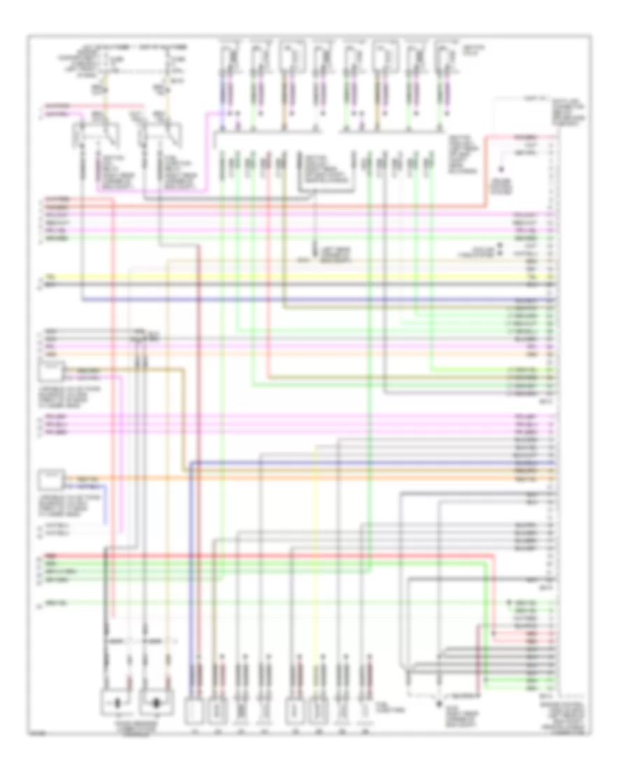
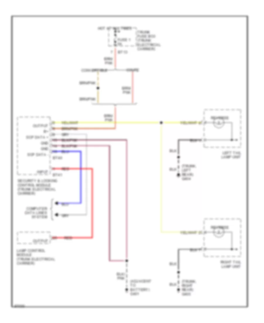
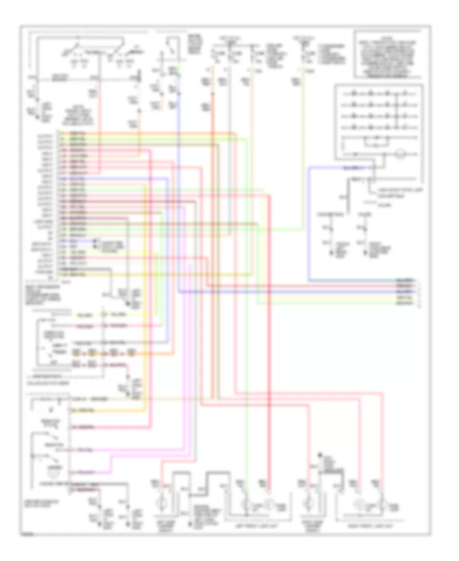
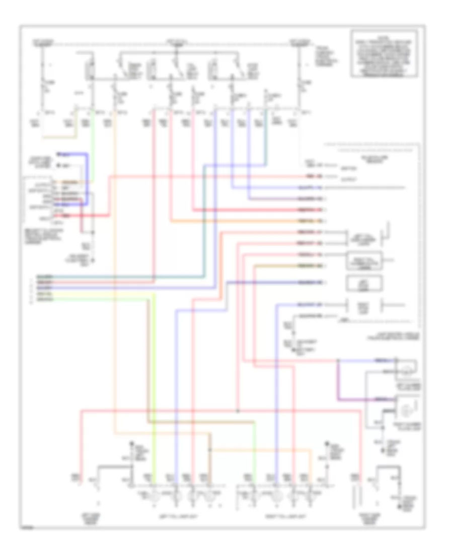
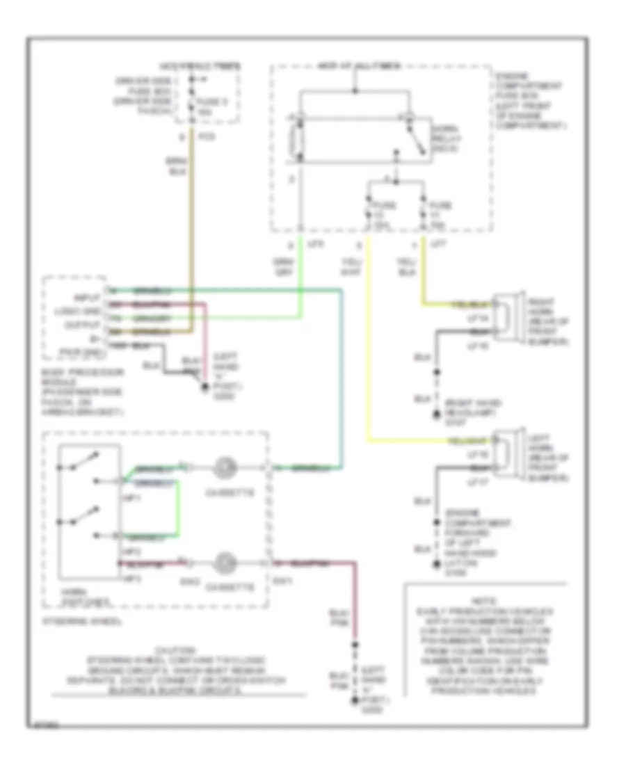
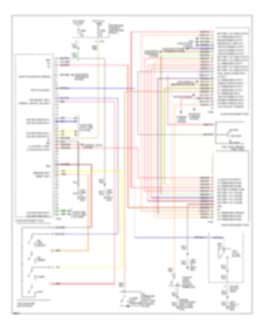
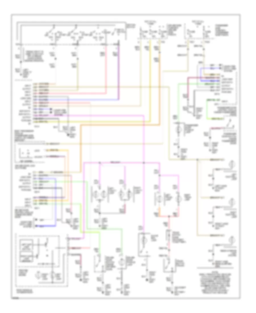
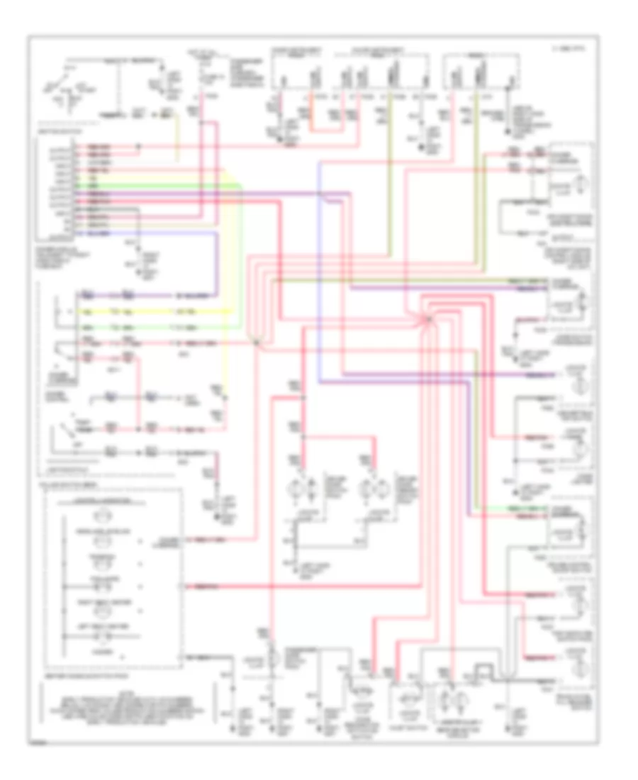
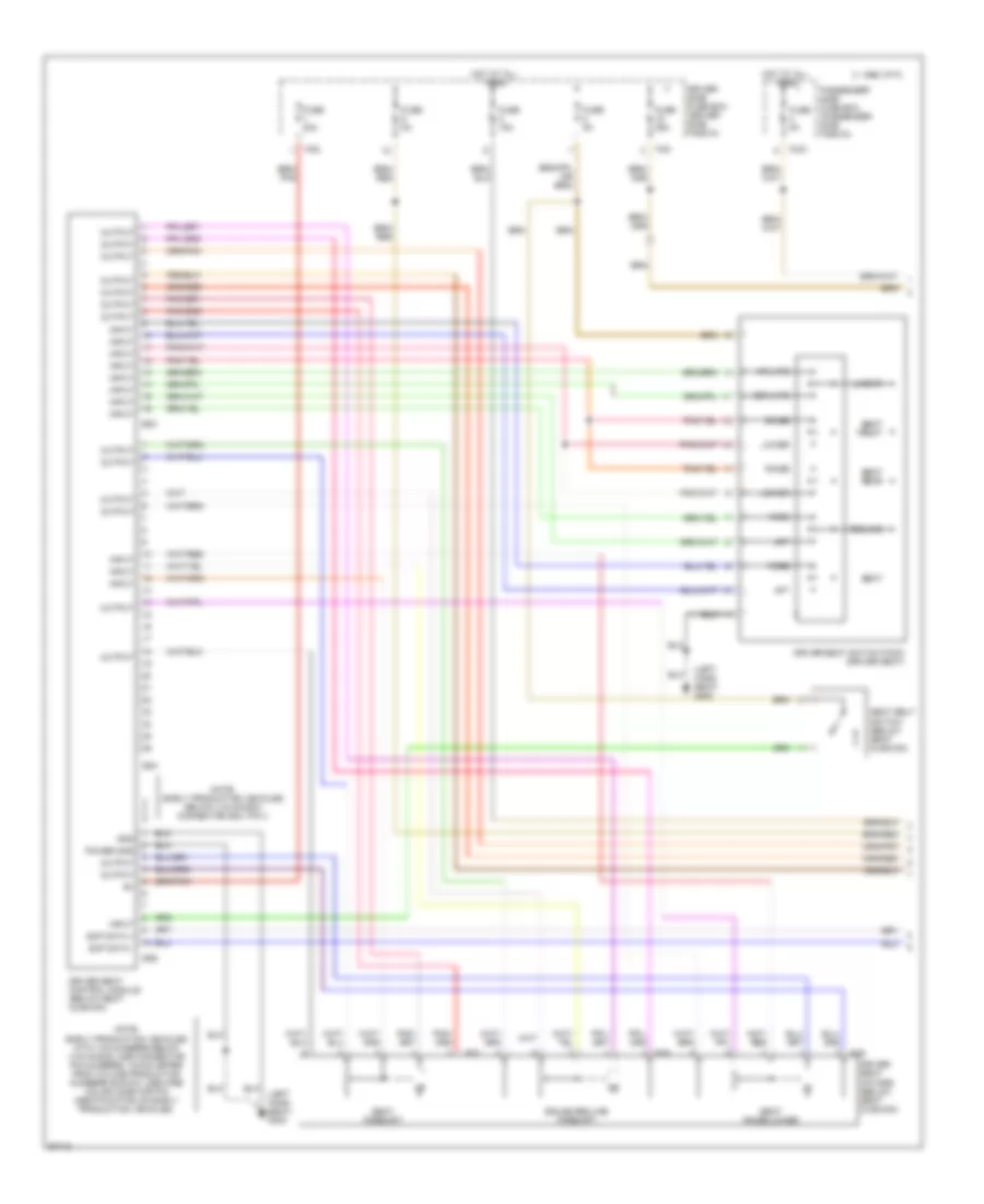
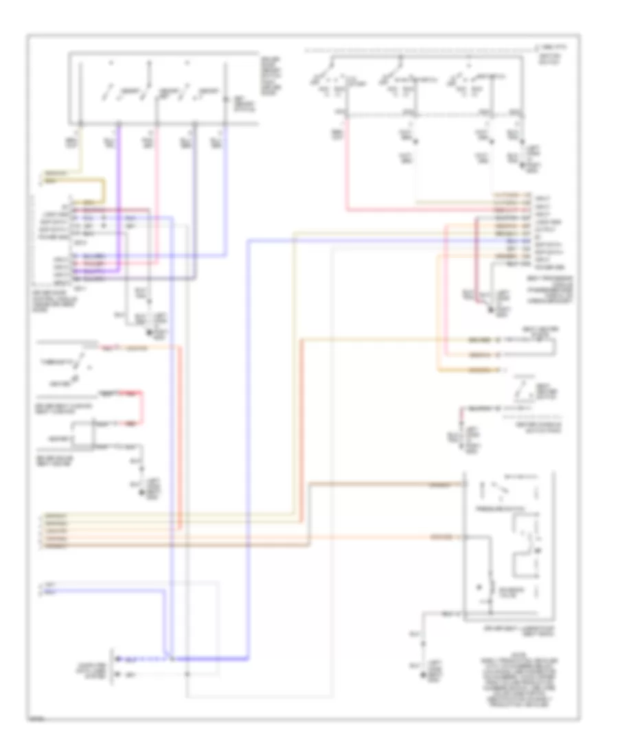
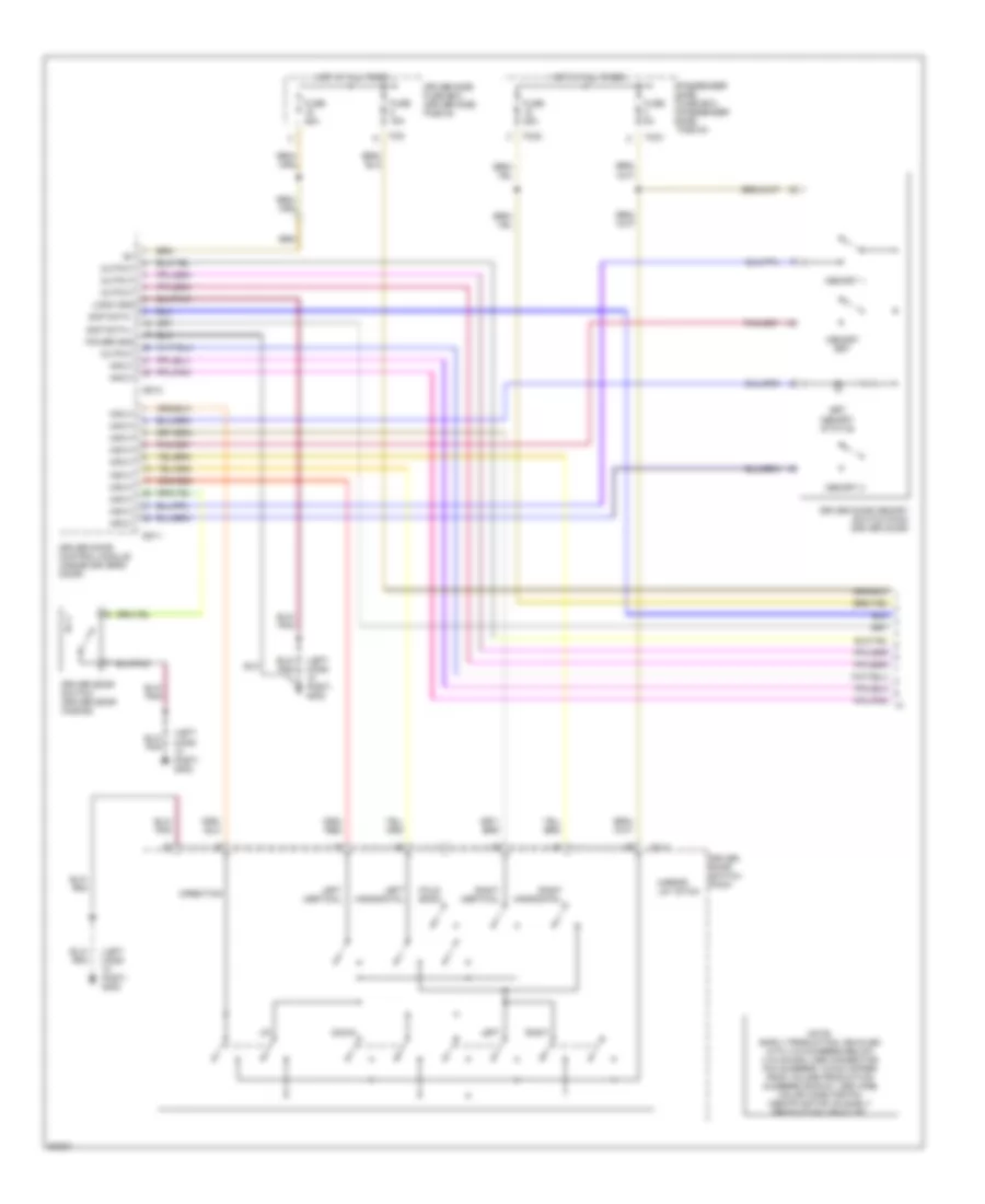
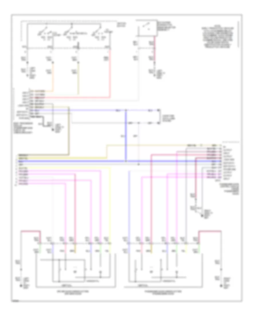
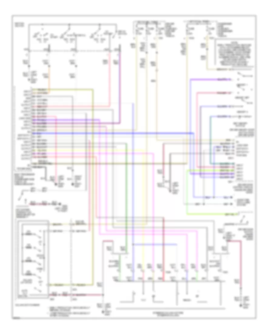
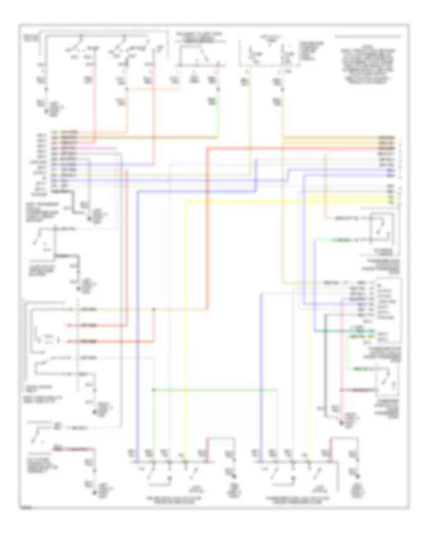
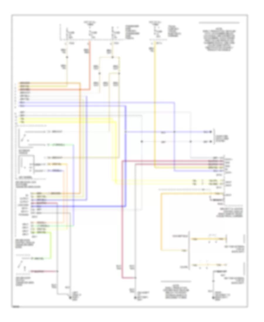
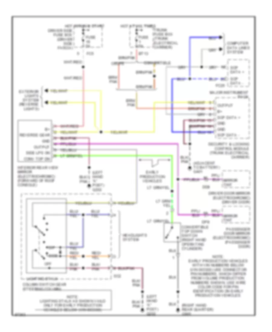
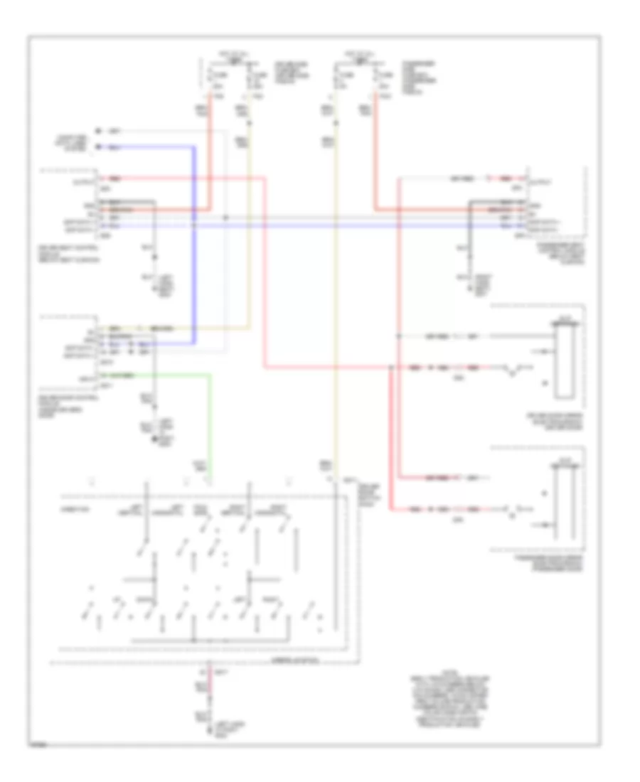
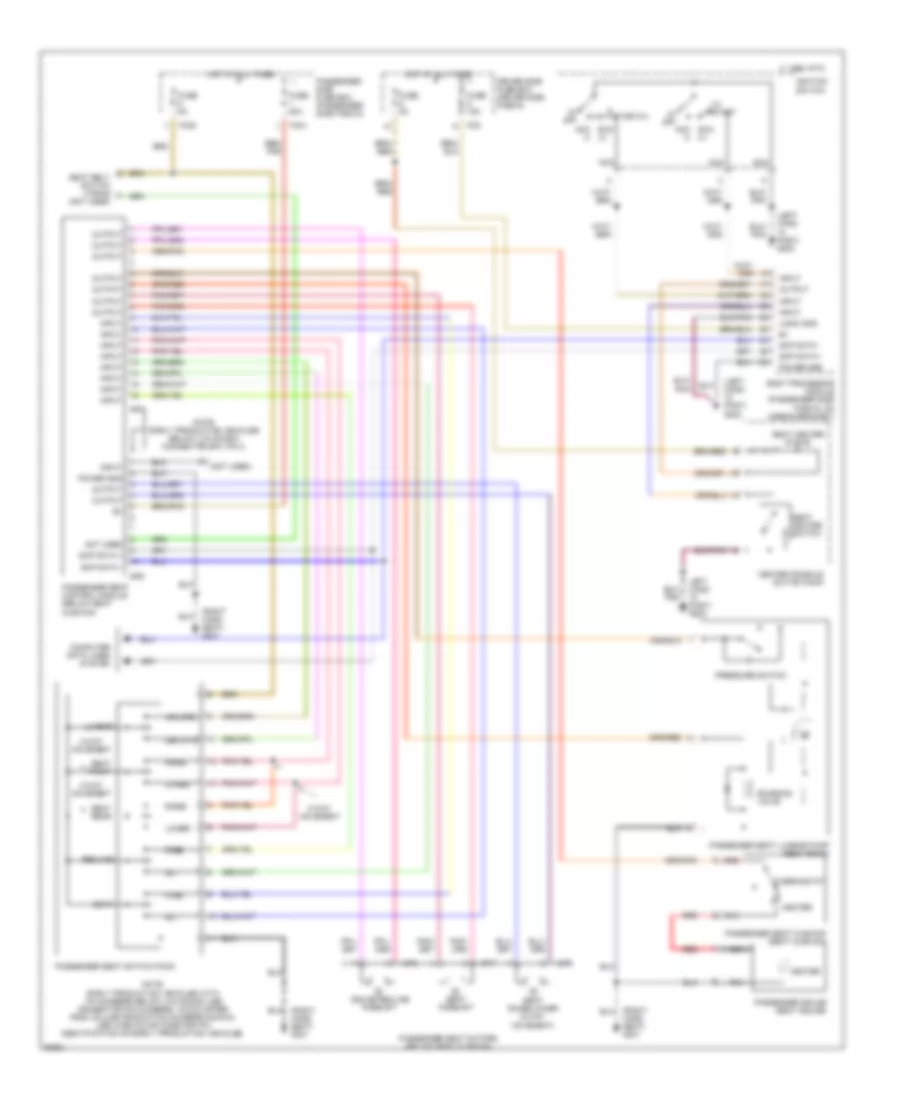
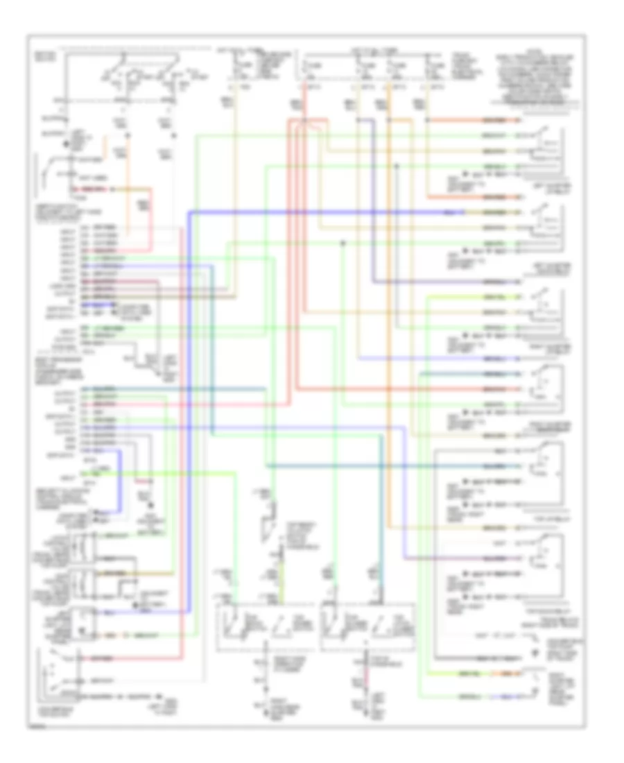
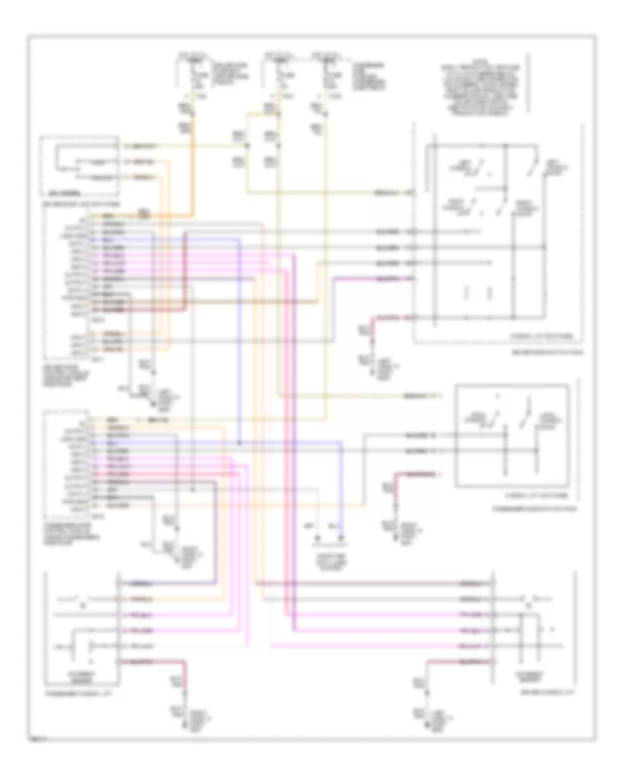
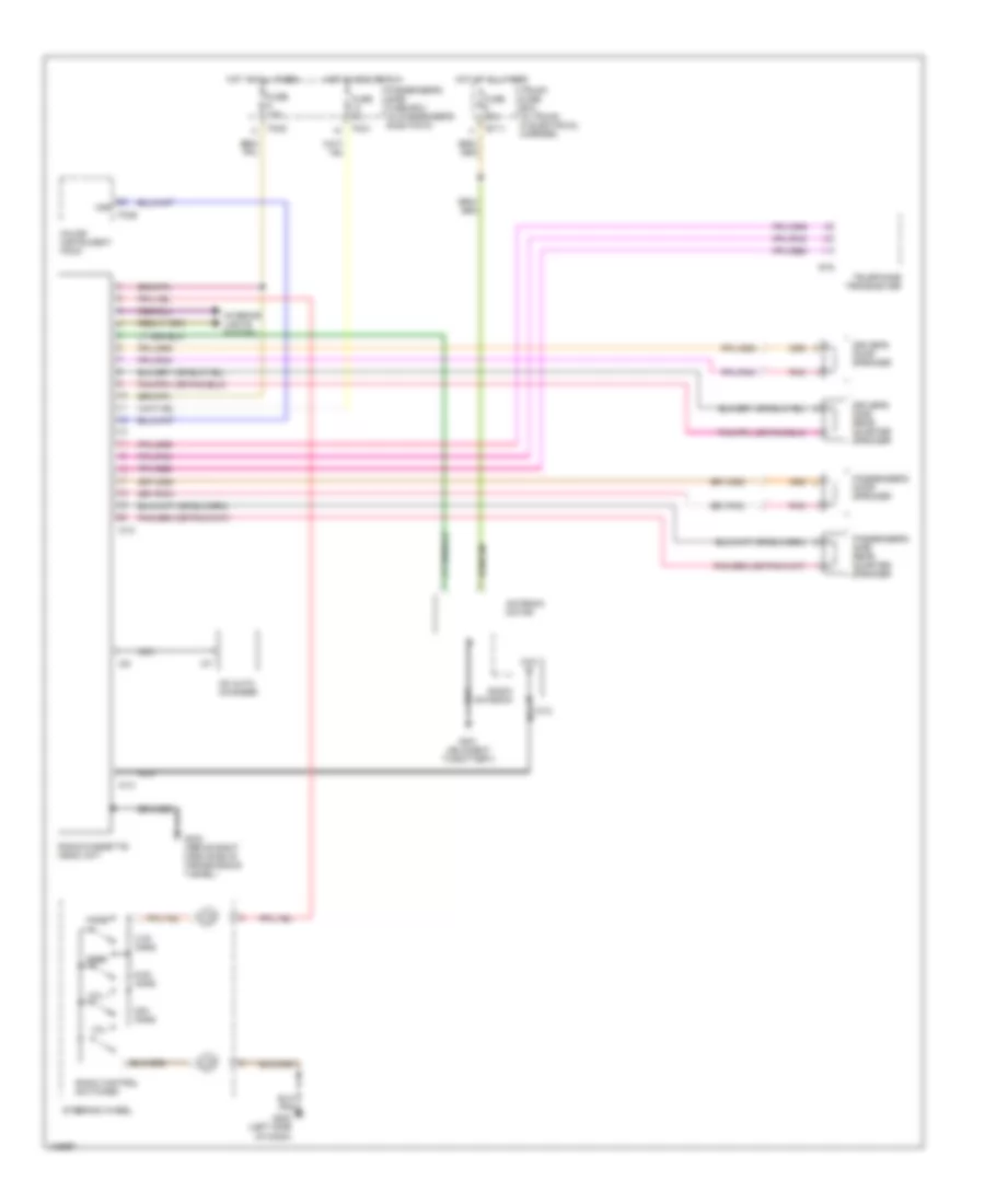
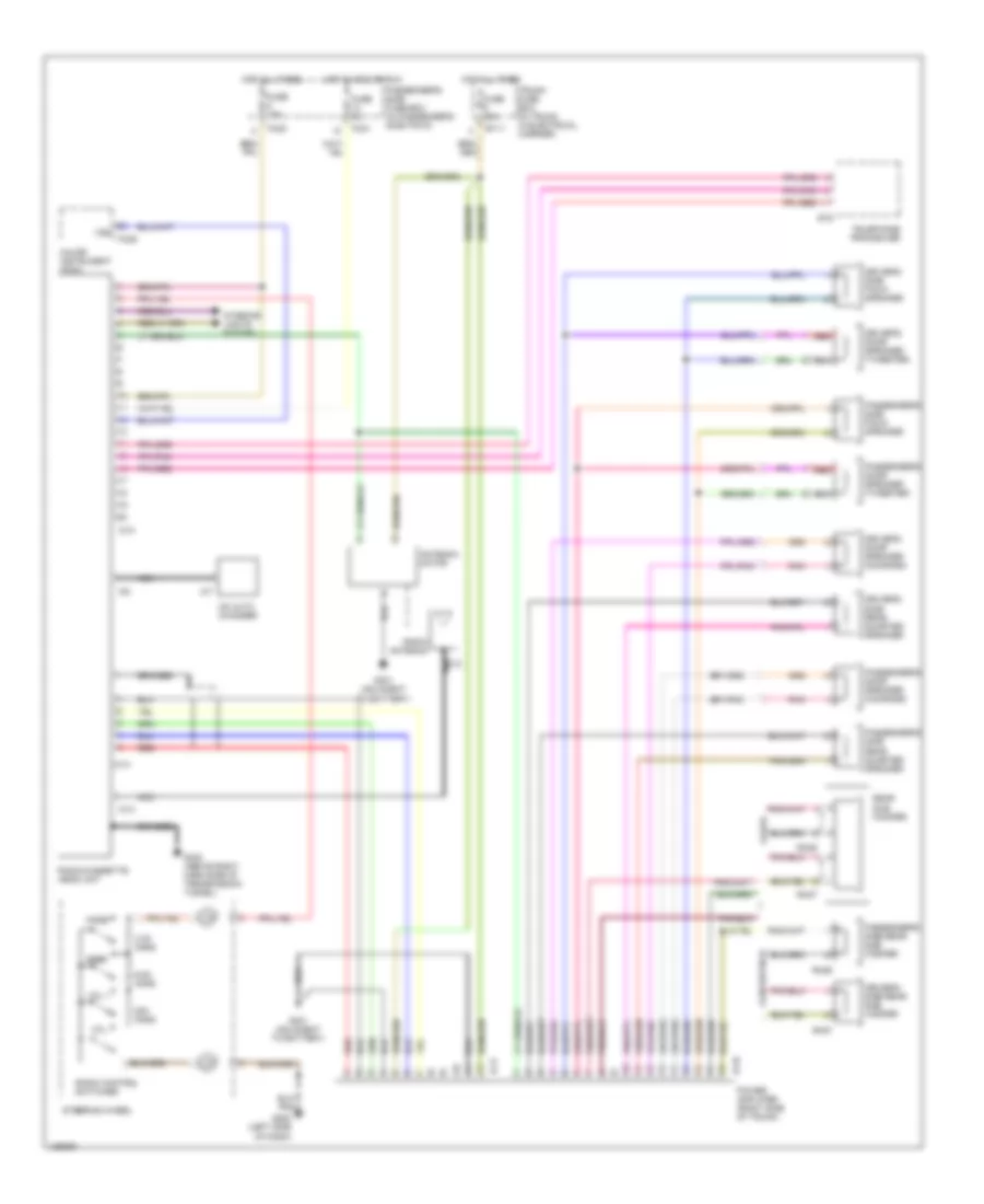
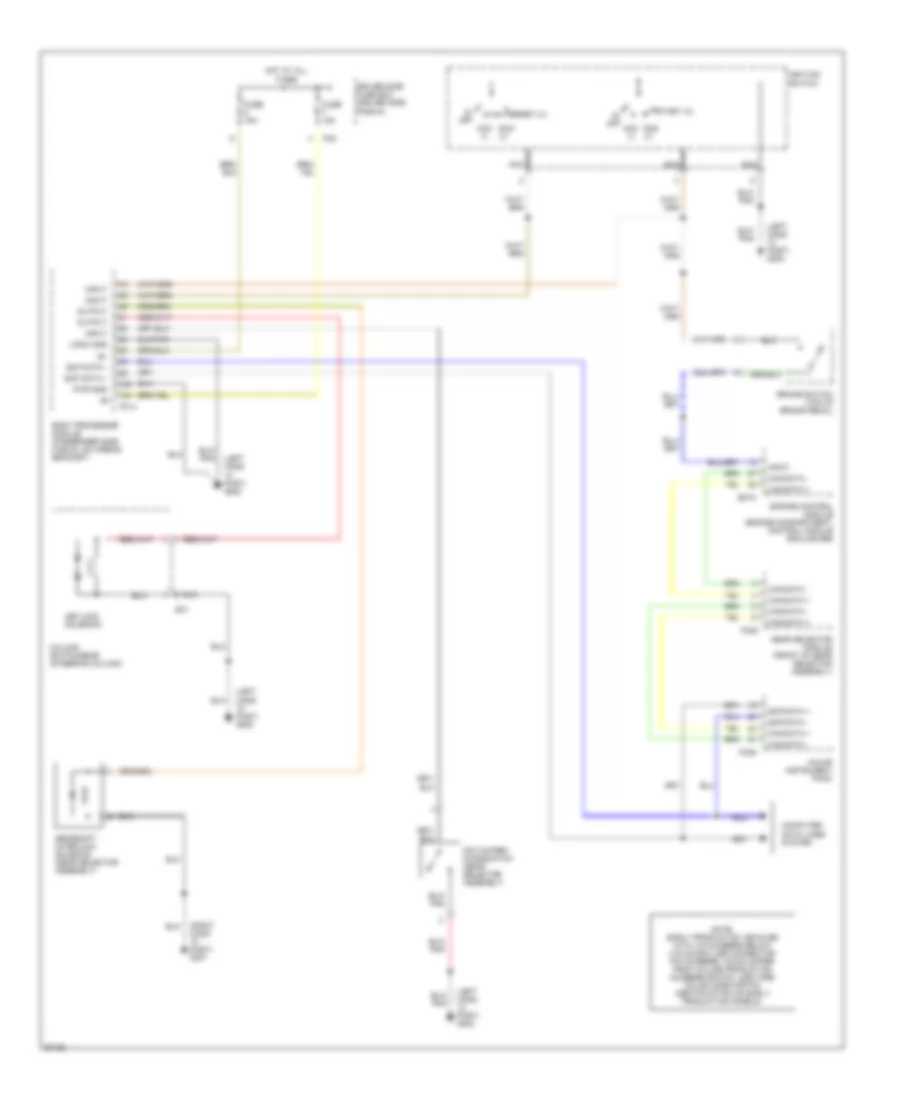
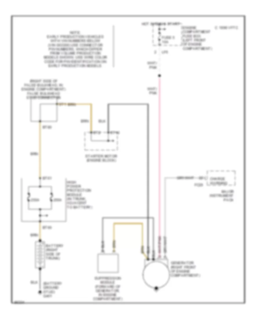
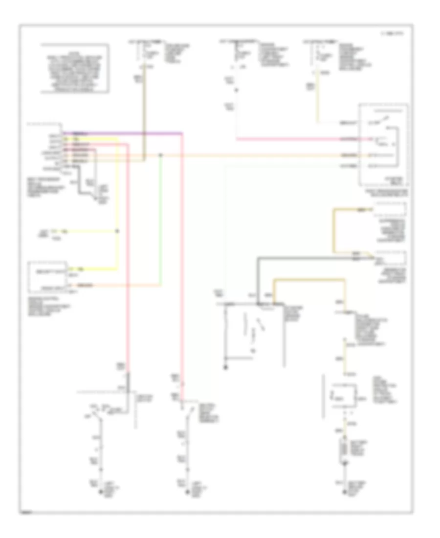
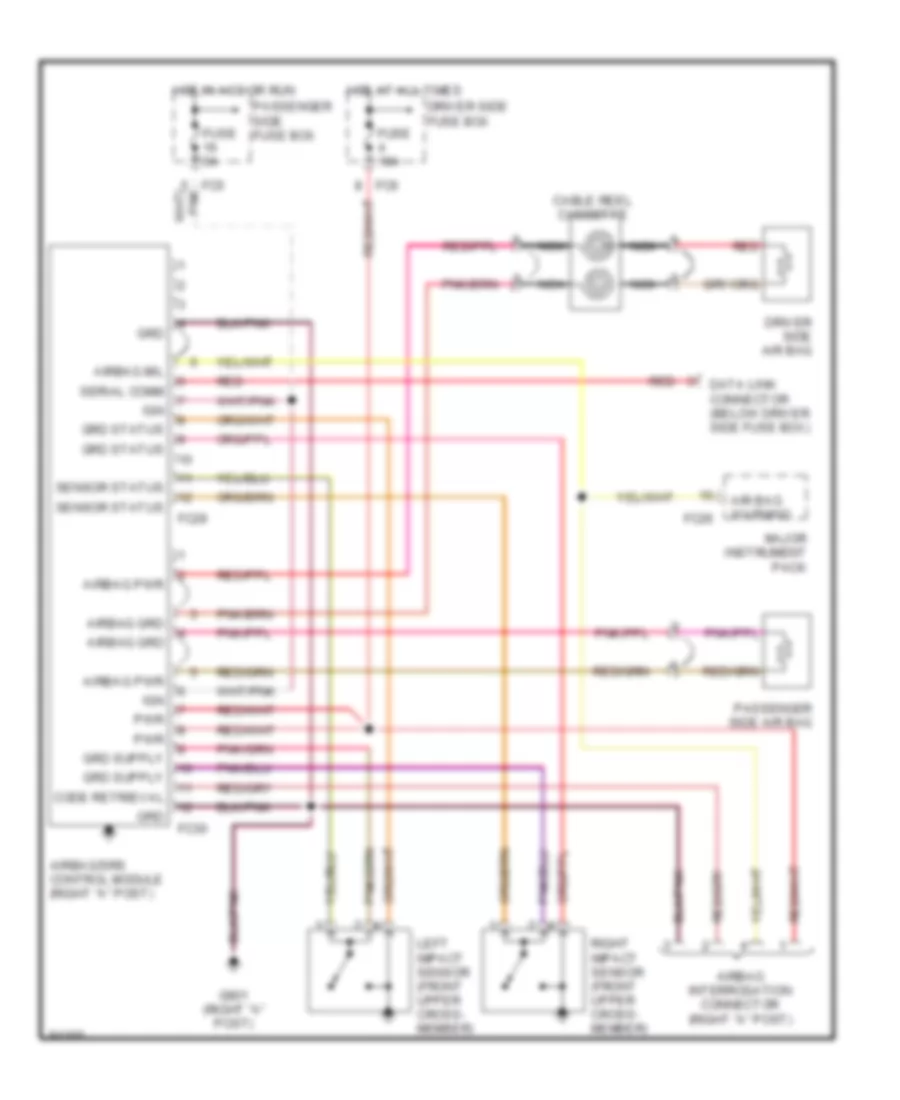
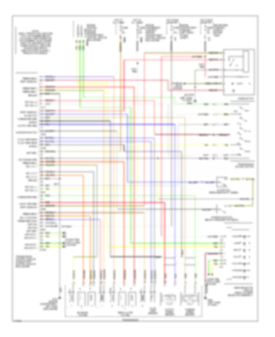
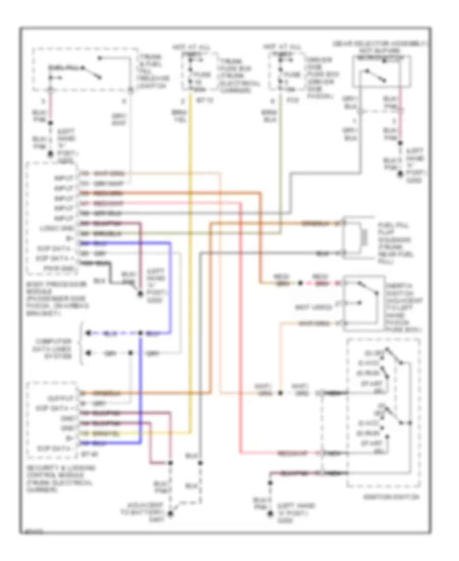
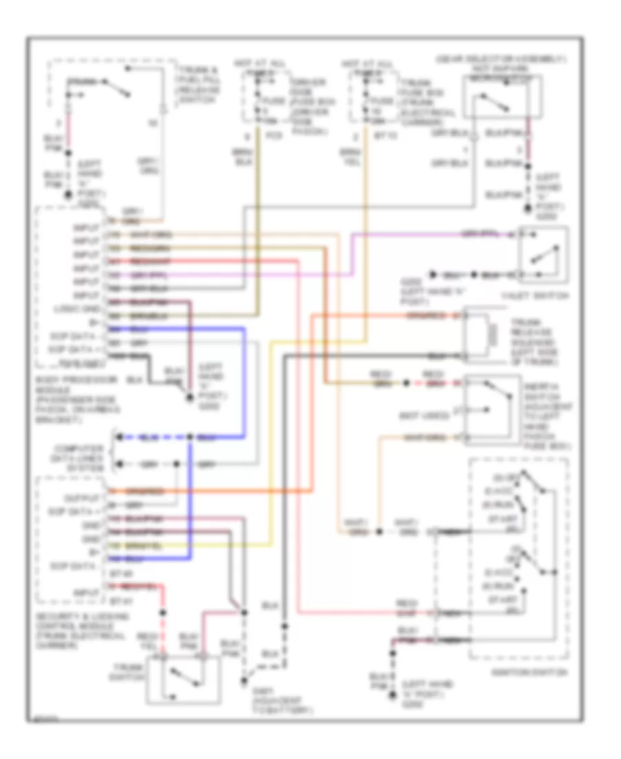
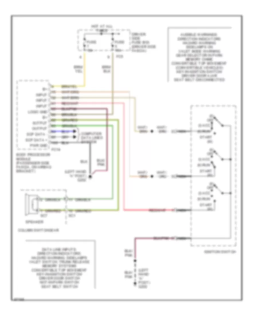
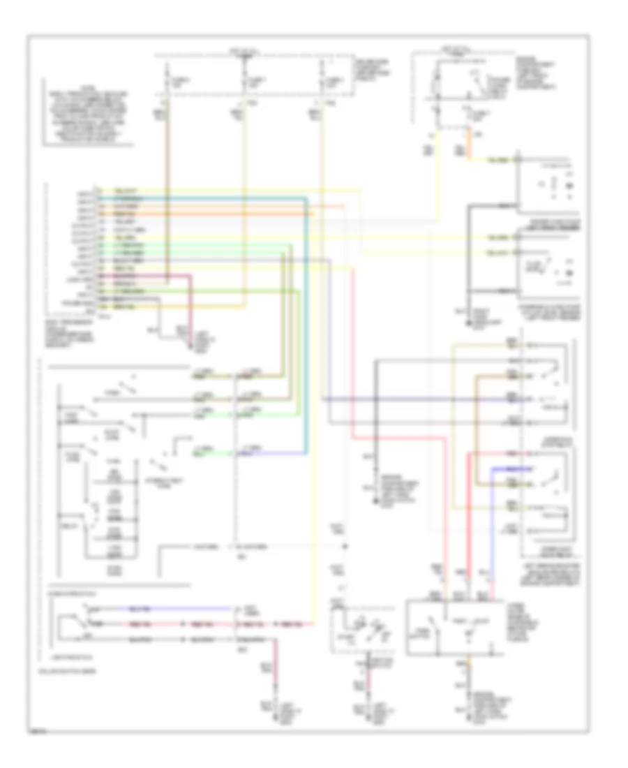
List of elements for Anti-theft Wiring Diagram for Jaguar XK8 1997:
71
(0) off
(adjacent to battery) g401
(engine compartment, right hand enclosure) g105
(iii) start
(left hand "a" post) g202
(right hand "a" post) g201
(roof, adjacent to backlight) g909
Acc (i)
B +
Body processor module (passenger side fascia, on airbag bracket)
Braided wire
Bt13
Bt40
Bt41
Computer data lines system
Convertible
Coupe
Data
Dd10
Dd11
Dp10
Dp11
Driver door control module (inside driver's door)
Driver door lock swtches
Driver door switch (inside driver's door)
Driver side fuse box (driver side fascia)
Em10
Engine compartment security switch (in engine compartment, near right hand hood latch)
Engine control module (engine compartment, control module enclosure)
Fc14
Fc20
Fc21
Fc25
Fc5
Fuse 15a
Fuse 20a
Fuse 25a
Fuse 5a
Gnd
Horns system
Hot at all times
Ignition switch
Input
Key barrel
Key fob antenna (top of backlight)
Key in
Lock
Logic gnd
Major instrument pack
Nca
Note: early production convertible vehicles (below vin 003300)- antenna shield is grounded to g909.
Note; early production vehicles with vin numbers below (vin 003300) use connector pin numbers, which differ from volume production numbers shown. use wire color code for pin identification on early production models.
Output
Passenger door control module (inside passenger's door)
Passenger door switch (inside passenger's door)
Passenger side fuse box (passenger side fascia)
Pwr gnd
Rh20
Rh7
Run (ii)
Scp data +
Scp data -
Security & locking control module (trunk, electrical carrier)
Security acknowledge
Security active indicator (gear selector module) (in front of gear selector module)
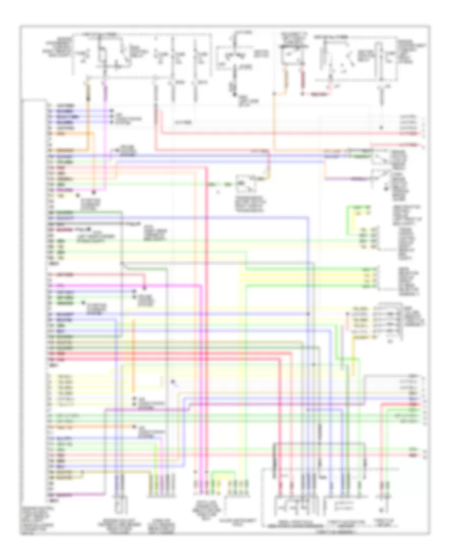
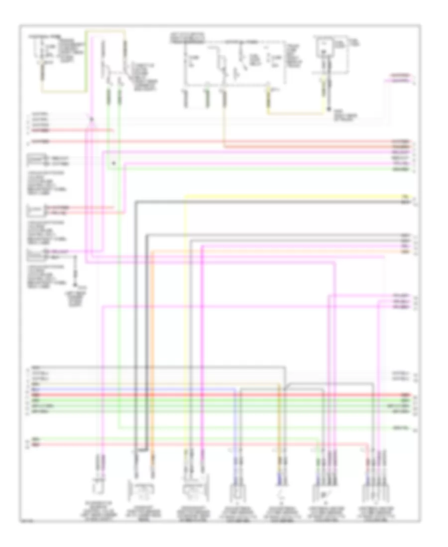
List of elements for Computer Data Lines for Jaguar XK8 1997:
65
(0) off
(iii) start
(left hand "a" post) g202
(not used)
Abs/traction control module (left front of engine compartment)
Ac4
Acc (i)
Adaptive damping control module (in trunk, adjacent to electrical carrier)
Air conditioning control module (on a/c unit)
Airbag/ srs control module (right hand "a" post)
Body processor module (passenger side fascia, on airbag bracket)
Bt40
Bt69
Can data +
Can data -
Controller area network (can)
Data
Data link connector (below
Dd10
Dp10
Driver door control module (inside driver door)
Driver seat control module (below seat cushion)
Driver side fuse box (driver side fascia)
Driver side fuse box)
Early production vehicles (before vin 003300)
Em10
Em11
Em13
Em7
Engine control module (in engine compartment, control module enclosure)
F37
Fc14
Fc22
Fc25
Fc29
Fc5
Fc88
Fccp data
Fuse 5a
Gear selector module (front of gear selector assembly)
Hot at all times
Hot in run & start
Ignition switch
Key transponder module (adjacent to passenger side fuse box)
Lf37
Major instrument pack
Nca
Note: early production vehicles with vin numbers below (vin 003300) use connector pin numbers, which differ from volume production numbers shown. use wire color code for pin identification on early production models.
Note: fccp-flash communication control port; vfp-voltage, flash programming
Passenger door control module (inside passenger door)
Passenger seat control module (below seat cushion)
Pnk
Red
Run (ii)
Scp data +
Scp data -
Sd5
Security & locking control module (trunk electrical carrier)
Serial data link
Serial output data
Sp5
Standard corporate protocal network (scp)
Transmission control module (in engine compartment, control module enclosure)
List of elements for Defogger Wiring Diagram for Jaguar XK8 1997:
35
(engine compartment, left hand enclosure) g104
(engine compartment, right hand enclosure) g105
(left hand "a" post) g202
(left hand rear quarter) g904
(not used)
(right hand "a" post) g201
Ac1
Air conditioning control module (right side of a/c unit)
Bt10
Bt13
Door mirror heater relay
Driver side fuse box (driver side fascia)
Driver's mirror
Em19
Engine management fuse box (engine compartment, control module enclosure)
Fc5
Fc6
Fuse 10a
Fuse 25a
Fuse 30a
Fuse 5a
Heated backlight
Heated backlight relay (no.2)
Hot at all times
Hot in run & start
Left fascia relays (left side of i/p)
Left windshield heater
Left windshield heater relay
Note: early production vehicles with vin numbers below (vin 003300) use connector pin numbers, which differ from volume production numbers shown. use wire color code for pin identification on early production models.
Output
Passenger's mirror
Right brake booster enclosure relays (engine compartment, control module enclosure)
Right windshield heater
Right windshield heater relay
Trunk fuse box (trunk electrical carrier)
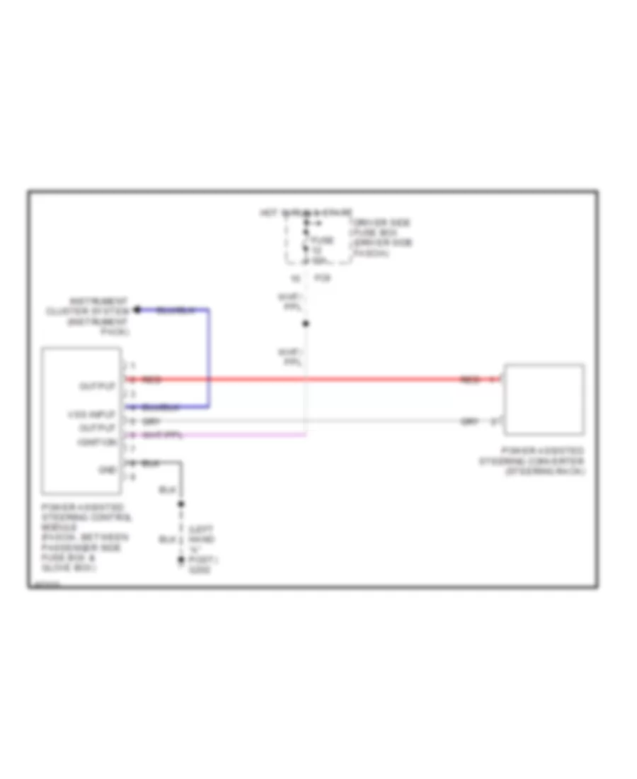
ELECTRONIC POWER STEERING
Electronic Power Steering Wiring Diagram for Jaguar XK8 1997
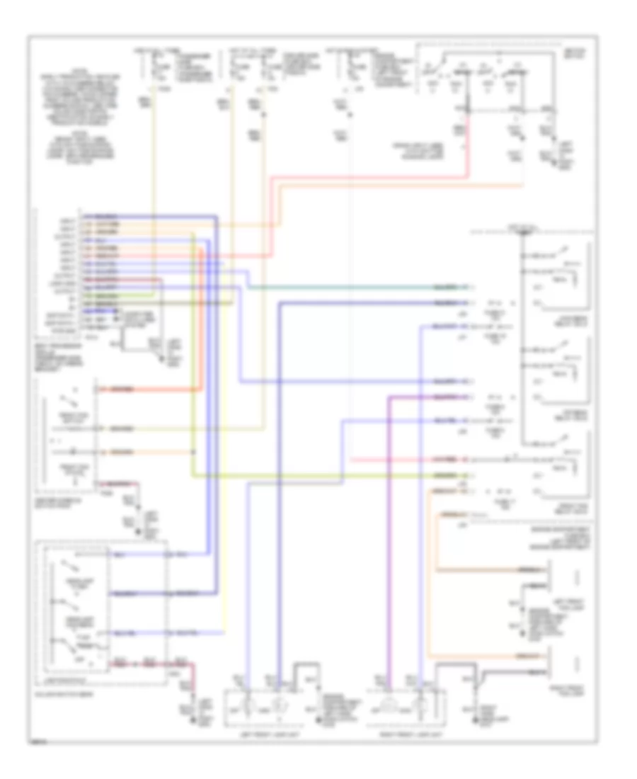
List of elements for Exterior Lamps Wiring Diagram (1 of 2) for Jaguar XK8 1997:
58
(0) off
(engine compartment, forward of left hand hood catch) g100
(i)
(ii)
(iii)
(left hand "a" post) g202
(right hand rear quarter) g905
(trunk, left rear) g405
9 or 16
Acc
Body processor module (passenger side fascia, on airbag bracket)
Brake switch (top of brake pedal)
Center console switch pack
Column switch gear
Computer data lines system
Convertible
Coupe
Dip
Direction indicator
Driver side fuse box (driver side fascia)
Fc14
Fc20
Fc5
Fuse 15a
Fuse 5a
G107 (right hand headlamp)
Hazard
Hazard state
High mount stop lamp
Hot at all times
Ignition switch
Input
Left front lamp unit
Left side marker (front)
Lighting stalk
Logic gnd
Nca
Note: "crank" input activates general bulb failure output.
Note: early production vehicles with vin numbers below (vin 003300) use connector pin numbers, which differ from volume production numbers shown. use wire color code for pin identification on early production models.
Off
Off (0) acc
Output
Passenger side fuse box (passenger side fascia)
Pnk
Pwr gnd
Rear fog
Rear fog state
Red/ pnk
Red/pnk
Right front lamp unit
Right side marker (front)
Run
Scp data +
Scp data -
Side
Side- lamp
Start
Turn (di)
Exterior Lamps Wiring Diagram (2 of 2) for Jaguar XK8 1997
List of elements for Exterior Lamps Wiring Diagram (2 of 2) for Jaguar XK8 1997:
50
(adjacent to battery) g401
(not used)
(trunk, left rear) g404
(trunk, right rear) g405
Bt10
Bt11
Bt12
Bt13
Bt40
Bt41
Bulb failure sensing
Computer data lines system
Fog
Fuse 10a
Fuse 5a
Fuse 6 5a
Fuse 8 5a
G404 (trunk, left rear)
G405 (trunk, right rear)
Gnd
Hot at all times
Hot in run & start
Ignition
Input
Lamp control module (trunk electrical carier)
Left number plate lamp
Left side marker (rear)
Left stop lamp
Left tail lamp unit
Left tail; side marker lamps
Note: early production vehicles with vin numbers below (vin 003300) use connector pin numbers, which differ from volume production numbers shown. use wire color code for pin identification on early production models.
Output
Rear fog relay (no.1)
Red
Red/ pnk
Red/pnk
Right number plate lamp
Right side marker (rear)
Right stop lamp
Right tail lamp unit
Right tail; number plate lamps
Scp data +
Scp data -
Security & locking control module (trunk electrical carrier)
Stop
Stop lamp relay (no.5)
Tail
Tail lamp relay (no.3)
Trunk fuse box (trunk, electrical carrier)
Turn (di)
GROUND DISTRIBUTION
Ground Distribution Wiring Diagram (1 of 2) for Jaguar XK8 1997
List of elements for Ground Distribution Wiring Diagram (1 of 2) for Jaguar XK8 1997:
20
Abs/traction control module wiper motor wiper run/ stop relay
Air conditioning control module auto tilt switch body processor module center console switch pack convertible top switch cruise control switches data link connector garage door opener gear selector module horn switches (steering wheel) ignition switch ignition switch (key-in switch) interior rear view mirror (electro-chromic) left vanity lamp lighting stalk major instrument pack minor instrument pack mode switch mode switch (transmission) neutral switch not-in-park microswitch radio control switches (steering wheel) right vanity lamp roof console seat heater switch steering column motors top closed switch top latch closed switch trip cycle switch trunk & fuel fill release switch
Air conditioning isolate relay center console switch pack cigar lighter convertible top switch cruise control on/off switch driver door control module driver door lock actuator driver door memory switch pack driver door mirror motors driver door puddle lamp driver door switch driver door switch pack driver mirror driver window lift gear selector module keylock solenoid left blower motor left footwell lamp major instrument pack mirror joy stick power assisted steering control module security active indicator (gear selector module) stability/ traction control switch trip computer switch pack trunk & fuel fill release switch valet switch window lift switches (driver door switch pack)
Airbag interrogation connector airbag/ srs control module
Braided wire
Coolant level switch engine compartment security switch engine control module right windshield heater
Driver seat control module driver seat lumbar pump driver squab
Ecm & tcm cooling fan fuel injection relay heater pump heater valve ignition module 1 ignition module 2 left windshield heater transmission control module vacuum switching valves
G100 (engine compartment, forward of left hand hood catch)
G104 (engine compartment, forward of left hand hood catch)
G104 (engine compartment, left hand enclosure)
G105 (engine compartment, right hand enclosure)
G107 (right hand headlamp)
G201 (right hand "a" post)
G202 (left hand "a" post)
G300 (left hand seat)
G302 (radio/cassette head unit ground) (above right hand side of transmission tunnel)
Left front fog lamp left front lamp unit left headlamp leveling actuator left horn left radiator fan left side marker radiator fan control relay module refrigerant 4-way pressure switch
Power wash pump right front fog lamp right front lamp unit right headlamp leveling actuator right horn right side marker windshield wash pump & fluid level sensor
Radio radio/ cassette head unit
Ground Distribution Wiring Diagram (2 of 2) for Jaguar XK8 1997
List of elements for Ground Distribution Wiring Diagram (2 of 2) for Jaguar XK8 1997:
18
Adaptive damping control module delay timer fuel pump right side marker right tail lamp unit top down relay top up relay trunk accessory connector
Antenna motor fuel fill flap solenoid lamp control module latch control valve left quarter down relay left quarter up relay main control valve power amplifier right quarter down relay right quarter up relay security & locking control module top down relay top up relay trunk release solenoid trunk switch
Aspirator assembly body processor module dimmer module door locking relay fascia accessory connector gearshift interlock solenoid glove box lamp passenger door control module passenger door lock actuator passenger door mirror motors passenger door puddle lamp passenger door switch passenger door switch pack passenger mirror passenger window lift right blower motor right footwell lamp telephone transceiver voice recognition activation switch window lift switches (passenger door switch pack)
Battery
Convertible top down switch high mount stop lamp (coupe) rear interior lamp (coupe) top down switch top raised switch
G201 (right hand "a" post)
G301 (right hand seat)
G401 (adjacent to battery)
G401 (battery ground stud)
G405 (trunk, left rear)
G405 (trunk, right rear)
G904 (left hand rear quarter)
G905 (right hand rear quarter)
G909 (roof, adjacent to backlight)
Heated backlight
High mount stop lamp (convertible) left number plate lamp left side marker left tail lamp unit right number plate lamp
List of elements for Headlamps Wiring Diagram for Jaguar XK8 1997:
63
(0)
(engine compartment, forward of left hand hood catch) g100
(i)
(ii)
(iii)
(left hand "a" post) g202
(right hand headlamp) g107
Acc
Body processor module (passenger side fascia, on airbag bracket)
Center console switch pack
Column switch gear
Computer data lines system
Crank input used with daytime running lamps
Dip
Dip beam relay (no.5)
Driver side fuse box (driver side fascia)
Engine compartment fuse box (left front of engine comartment)
Engine compartment fuse box (left front of engine compartment)
Fc14
Fc20
Fc5
Fc55
Front fog relay (no.2)
Front fog state
Front fog switch
Fuse 15a
Fuse 17 15a
Fuse 19 10a
Fuse 21 10a
Fuse 5a
Fuse 6 10a
Fuse 8 10a
Headlamp flash
Headlamp main beam
Hot at all times
Hot in run & start
Ignition switch
Input
Left front fog lamp
Left front lamp unit
Lf5
Lf6
Lf7
Lf8
Lighting stalk
Logic gnd
Main
Main beam relay (no.3)
Nca
Note: "crank" input used with daytime running lamps. daytime running lamps - bpm programmed function.
Note: early production vehicles with vin numbers below (vin 003300) use connector pin numbers, which differ from volume production numbers shown. use wire color code for pin identification on early production models.
Off
Output
Passenger side fuse box (passenger side fascia)
Pwr gnd
Right front fog lamp
Right front lamp unit
Run
Sc2
Scp data +
Scp data -
Side
Start
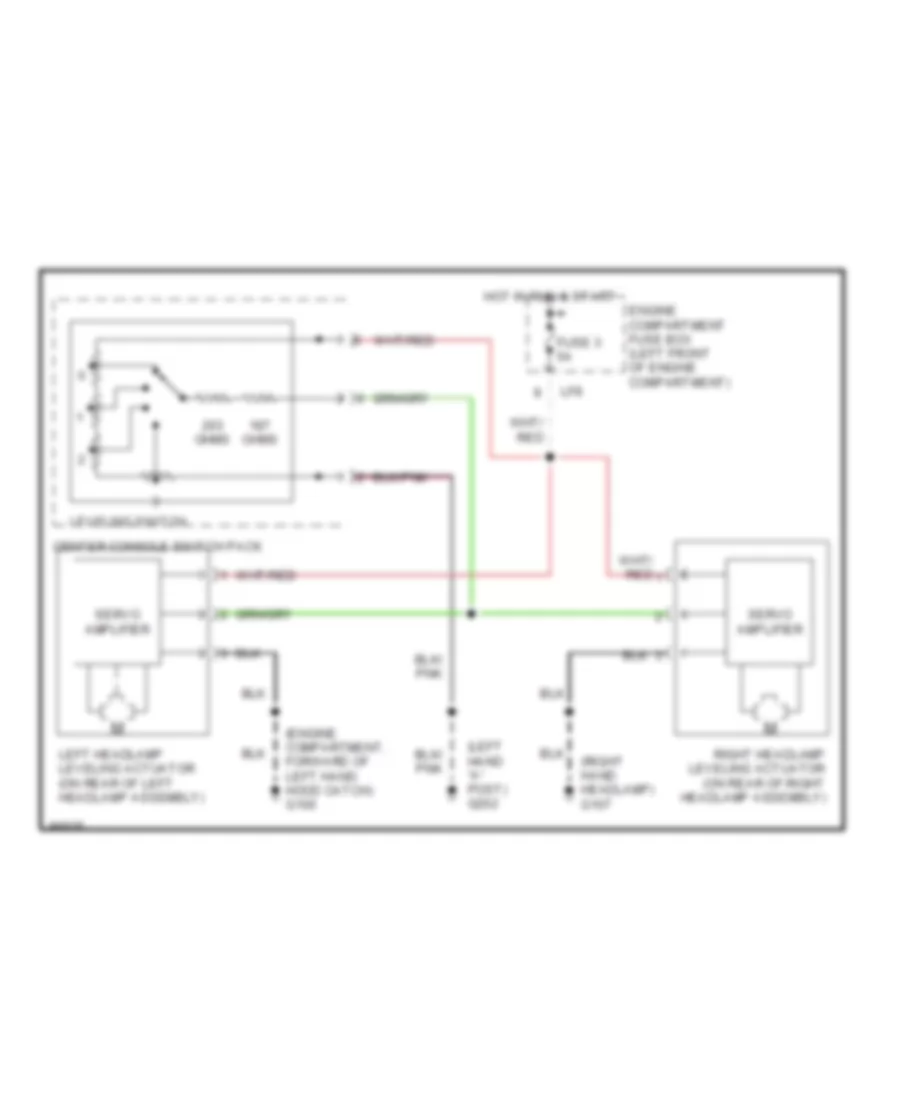
Headlamps Leveling Wiring Diagram for Jaguar XK8 1997
List of elements for Horn Wiring Diagram for Jaguar XK8 1997:
32
(engine compartment, forward of left hand hood latch) g100
(left hand "a" post) g202
(right hand headlamp) g107
Body processor module (passenger side fascia, on airbag bracket)
Cassette
Driver side fuse box (driver side fascia)
Engine compartment fuse box (left front of engine compartment)
Fc5
Fuse 10a
Fuse 5 15a
Horn relay (no.6)
Horn switches
Hot at all times
Hp1
Hp2
Hp3
Input
Left horn (rear of front bumper)
Lf14
Lf15
Lf16
Lf17
Lf6
Lf7
Logic gnd
Note: early production vehicles with vin numbers below (vin 003300) use connector pin numbers, which differ from volume production numbers shown. use wire color code for pin identification on early production vehicles.
Output
Pwr gnd
Right horn (rear of front bumper)
Steering wheel
Sw1
Sw2
INSTRUMENT CLUSTER
Instrument Cluster Wiring Diagram for Jaguar XK8 1997
List of elements for Courtesy Lamps Wiring Diagram for Jaguar XK8 1997:
65
"crank input" is used to switch off interior lamps during engine cranking.
(0) off
(adjacent to battery) g401
(i)
(iii) start
(left hand "a" post) g202
(right hand "a" post) g201
(right hand rear quarter) g905
Acc (i)
Acc run (ii)
Body processor module (passenger side fascia, on airbag bracket)
Computer data lines system
Dd10
Dd11
Dp10
Dp11
Driver door control module (inside driver's door)
Driver door lock switches
Driver door puddle lamp
Driver door switch (inside driver's door)
Driver side fuse box (driver side fascia)
Fc14
Fc20
Fc21
Fc5
Fuse 15a
Fuse 25a
Fuse 5a
Glove box lamp
Hand "a" post) g202
Hot at all times
Ignition switch
Input
Key barrel
Key-in switch
Left footwell lamp
Left map lamp
Left map lamp switch
Left trunk lamp
Left vanity lamp
Lock
Logic gnd
Nca
Note; early production vehicles with vin numbers below (vin 003300) use connector pin numbers, which differ from volume production numbers shown. use wire color code for pin identification on early production vehicles.
Output
Passenger door control module (inside passenger's door)
Passenger door puddle lamp
Passenger door switch (inside passenger's door)
Passenger side fuse box (passenger side fascia)
Pnk
Printed circuit board
Pwr gnd
Rear interior lamp (coupe)
Right footwell lamp
Right map lamp
Right map lamp switch
Right trunk lamp
Right vanity lamp
Roof console (interior roof)
Run (ii)
Scp data +
Scp data -
Trunk switch (trunk)
Trunk switch diode (adjacent to battery)
Unlock
Instrument Illumination Wiring Diagram for Jaguar XK8 1997
List of elements for Instrument Illumination Wiring Diagram for Jaguar XK8 1997:
74
(0) off
(above right hand side of transmission tunnel) g302
(iii) start
(left hand "a" post) g202
(not used)
(right hand "a" post) g201
1996 vftc c
Ac4
Acc (i)
Air conditioning control module (right side of a/c unit)
Air conditioning control panel
Braided wire
Center console switch pack
Cigar lighter
Column switch gear
Convertible top switch
Cruise control on/off switch
Dimmer control
Dimmer module (adjacent to right hand fascia fuse box)
Dimmer override
Dip
Driver door memory switch pack
Driver door switch pack
Fc20
Fc25
Fc26
Fc27
Fc35
Fc41
Fc42
Fc43
Fc59
Fc62
Fc63
Fc79
Fog lamps
Fuse 18 10a
Gear selector module
Gnd
Hazard
Headlamp leveling
Hot at all times
Ic10
Ignition switch
Input
Left seat heater
Lighting stalk
Locate illum
Locate illumination
Major instrument pack
Minor instrument pack
Mode switch (transmission)
Nca
Note: early production vehicles with vin numbers below (vin 003300) use connector pin numbers, which differ from volume production numbers shown. use wire color code for pin identification on early production vehicles.
Off
Output
Override dimmer
Passenger door switch pack
Passenger side fuse box (passenger side fascia)
Radio
Red
Red/ pnk
Red/pnk
Right seat heater
Run (ii)
Sc11
Sc2
Sc3
Side
Traction
Trip computer switch pack
Trunk & fuel fill release switch
Valet switch
Voice recognition activation switch
MEMORY SYSTEMS
Driver's Memory Seat Wiring Diagram (1 of 2) for Jaguar XK8 1997
List of elements for Driver's Memory Seat Wiring Diagram (1 of 2) for Jaguar XK8 1997:
44
(left hand seat) g300
1996 vftc c
Aft
Deflate
Driver seat control module (below seat cushion)
Driver seat motors (below seat cushion)
Driver seat switch pack (driver seat)
Driver side fuse box (driver side fascia)
Fc21
Fc5
Fc6
Fore
Fuse 15a
Fuse 20a
Fuse 25a
Fuse 5a
Gnd
Hot at all times
Inflate
Input
Lower
Lumbar
Note: early production vehicles below (vin 003300) connector sd4, pin 3.
Note: early production vehicles with vin numbers below (vin 003300) use connector pin numbers, which differ from volume production numbers shown. use wire color code for pin identification on early production vehicles.
Output
Passenger side fuse box (passenger side fascia)
Power gnd
Raise
Recline
Scp data +
Scp data -
Sd3
Sd4
Sd5
Sd7
Sd8
Sd9
Seat
Seat belt switch (below seat cushion)
Seat fore/aft
Seat front
Seat raise/lower
Seat rear
Squab recline fore/aft
Driver's Memory Seat Wiring Diagram (2 of 2) for Jaguar XK8 1997
List of elements for Driver's Memory Seat Wiring Diagram (2 of 2) for Jaguar XK8 1997:
38
(0) off
(i)
(iii) start
(left hand "a" post) g202
(left hand seat) g300
1996 vftc c
Acc run (ii)
Body processor module (passenger side fascia, on airbag bracket)
Center console switch pack
Computer data lines system
Dd10
Dd11
Driver door control module (inside driver's door)
Driver door memory switch pack (driver door)
Driver seat cushion (seat cushion)
Driver seat lumbar pump (seat back)
Driver squab (seat squab)
Heater
Ignition switch
Input
Left hand "a" post) g202
Logic gnd
Memory
Memory set
Nca
Note: early production vehicles with vin numbers below (vin 003300) use connector pin numbers, which differ from volume production numbers shown. use wire color code for pin identification on early production vehicles.
Output
Power gnd
Pressure switch
Red
Scp data +
Scp data -
Seat heater state
Seat heater switch
Set memory status
Solenoid valve
Start(iii)
Thermostat
Memory Mirrors Wiring Diagram (1 of 2) for Jaguar XK8 1997
List of elements for Memory Mirrors Wiring Diagram (1 of 2) for Jaguar XK8 1997:
38
(left hand "a" post) g202
Dd10
Dd11
Dd17
Direction
Down
Driver door control module (inside driver's door)
Driver door memory switch pack (driver door)
Driver door switch (driver door casing)
Driver door switch pack
Driver side fuse box (driver side fascia)
Fc20
Fc21
Fc5
Fold- back
Fuse 15a
Fuse 25a
Fuse 5a
Hot at all times
Input
Left
Left horizontal
Left vertical
Logic gnd
Memory 1
Memory 2
Memory set
Mirror joy stick
Note: early production vehicles with vin numbers below (vin 003300) use connector pin numbers, which differ from volume production numbers shown. use wire color code for pin identification on early production vehicles.
Output
Passenger side fuse box (passenger side fascia)
Power gnd
Right
Right horizontal
Right vertical
Scp data +
Scp data -
Set memory status
Memory Mirrors Wiring Diagram (2 of 2) for Jaguar XK8 1997
List of elements for Memory Mirrors Wiring Diagram (2 of 2) for Jaguar XK8 1997:
27
(0) off
(i)
(iii) start
(left hand "a" post) g202
(right hand "a" post) g201
Acc run (ii)
Body processor module (passenger side fascia, on airbag bracket)
Computer data lines system
Dp10
Driver door mirror motors (driver's door)
Horizontal
Ignition switch
Input
Logic gnd
Nca
Not-in-park microswitch (gear selector assembly)
Note: early production vehicles with vin numbers below (vin 003300) use connector pin numbers, which differ from volume production numbers shown. use wire color code for pin identification on early production vehicles.
Output
Passenger door control module (inside passenger's door)
Passenger door mirror motors (passenger's door)
Pnk
Power gnd
Pwr gnd
Scp data +
Scp data -
Start(iii)
Vertical
Steering Column Movement Wiring Diagram for Jaguar XK8 1997
List of elements for Steering Column Movement Wiring Diagram for Jaguar XK8 1997:
61
(0) off
(i)
(iii) start
(left hand "a" post) g202
(right hand "a" post) g201
Acc run (ii)
Aft
Auto tilt switch
Body processor module (passenger side fascia, on airbag bracket)
Column joy stick
Column switchgear
Computer data lines system
Dd10
Dd11
Down
Driver door control module (inside driver's door)
Driver door switch (inside driver's door)
Driver memory door switch pack (driver door)
Driver side fuse box (driver side fascia)
Early production vehicles built * before vin 003300
Fc20
Fc21
Fc5
Fc60
Fc61
Fore
Fuse 15a
Fuse 20a
Fuse 25a
Fuse 5a
G202 (left hand "a" post)
Gnd
Hot at all times
Ignition switch
Input
Key-in switch
Later production vehicles built ** after vin 003300
Logic gnd
Memory 1
Memory 2
Memory set
Nca
Not-in-park microswitch (gear selector assembly)
Note: early production vehicles with vin numbers below (vin 003300) use connector pin numbers, which differ from volume production numbers shown. use wire color code for pin identification on early production vehicles.
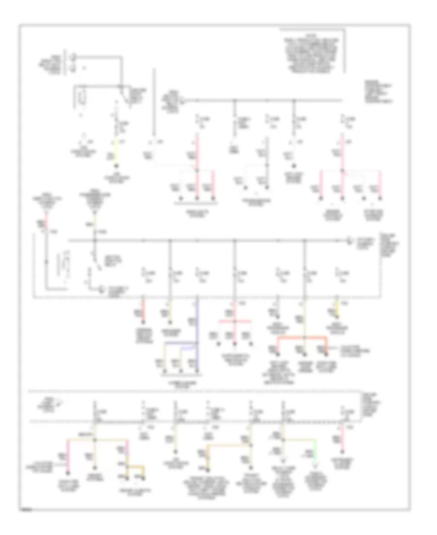
List of elements for Power Distribution Wiring Diagram (1 of 6) for Jaguar XK8 1997:
80
(0) off
(i) acc
(ii) run
(iii) start
(left hand "a" post) g202
(not used)
(trunk, right rear) g405
250a
250a (x2)
25a
After dealer prep
Air conditioning system
An1
Battery
Before dealer prep
Body processor module (passenger side fascia, airbag bracket)
Bt44
Bt60
Bt61
Bt62
Bt63
Bt65
Bt66
Bt79
Bt80
Defogger system
Delay timer (trunk, adjacent to battery)
Em10
Em19
Em20
Em70
Em71
Ems control relay
Engine control module (engine compartment, control module enclosure)
Engine controls system
Engine management fuse box (engine compartment, control module enclosure)
False bulkhead stud connector (engine compartment, right side of false bulkhead)
Fc14
Fc91
From driver side fuse box (fuse 17, 10a) (diagram 3 of 6)
Fuse 1 (not used)
Fuse 10a
Fuse 11 (not used)
Fuse 13 (not used)
Fuse 2 (not used)
Fuse 25a
Fuse 30a
Fuse 5a
Fuse 6 (not used)
Fuse 7 (not used)
Generator (right front of engine compartment)
Harness removed during dealer prep
High power protection module (trunk, adjacent to battery)
Ignition switch
Inertia switch (adjacent to left hand fascia fuse box)
Input
Lf71
Lt1
Note: early production vehicles with vin numbers below (vin 003300) use connector pin numbers, which differ from volume production models shown. use wire color code for pin identification on early production models.
Output
Pnk
Power windows system, drivers side & passengers side fuse boxes
Red
St1
St10
St11
St2
Starter motor (engine block)
Starting/ charging system
Suppression module (engine compartment, forward of generator)
To driver side fuse box (diagram 3 of 6)
To engine compartment fuse box (diagram 2 of 6)
To fuse 10 (diagram 2 of 6)
To passenger side fuse box (diagram 4 of 6)
To trunk fuse box (diagram 5 of 6)
To trunk fuse box (diagram 6 of 6)
Transit isolation device (trunk, adjacent to battery)
Transit isolation diode (lt2) (trunk, adjacent to battery)
Transmissions system
Tunnel stud connector (transmission tunnel)
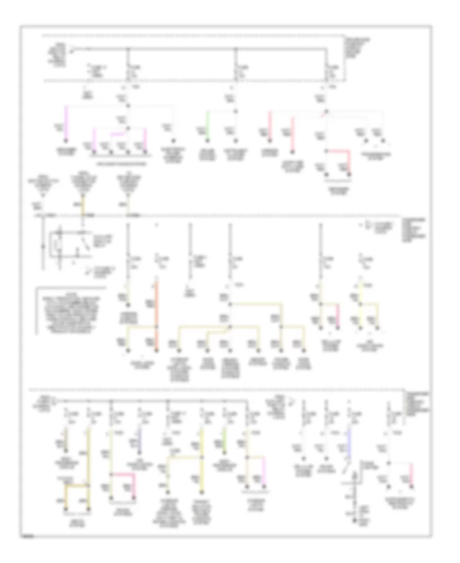
Power Distribution Wiring Diagram (2 of 6) for Jaguar XK8 1997
List of elements for Power Distribution Wiring Diagram (2 of 6) for Jaguar XK8 1997:
47
(headlights system)
(horns system)
(not used)
(wiper/ washer system)
Air conditioning system
Anti-lock brakes system
Cooling fans system
Dip beam relay (no.5)
Em19
Em20
Engine compartment fuse box (left front engine compartment)
Engine controls system
Engine management fuse box (engine compartment, control module enclosure)
From ems control e relay (diagram 1 of 6)
From inertia switch diagram (1 of 6)
From power wash relay (n0.4) (diagram 2 of 6)
From tunnel stud connector (diagram 1 of 6)
Front fog relay (no.2)
Fuse 10 (not used)
Fuse 10a
Fuse 17 15a
Fuse 19 10a
Fuse 20 (not used)
Fuse 21 10a
Fuse 22 (not used)
Fuse 30a
Fuse 5a
Fuse 6 10a
Fuse 8 10a
Fuse 9 (not used)
Headlights system
Horn relay (no.6)
Horns system
Ignition positive relay
Lf5
Lf6
Lf7
Lf70
Lf8
Main beam relay (no.3)
Note: early production vehicles with vin numbers below (vin 003300) use connector pin numbers, which differ from volume production models shown. use wire color code for pin identification on early production models.
Power- wash relay (no.4)
To fuse 3 diagram (3 of 6)
To heater pump relay (no.1) (diagram 3 of 6)
To main beam relay (no.3) (diagram 2 of 6)
Transmissions system
Wiper/ washer system
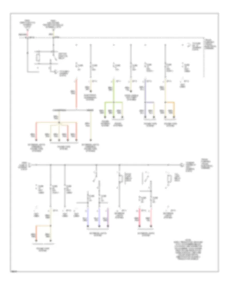
Power Distribution Wiring Diagram (3 of 6) for Jaguar XK8 1997
List of elements for Power Distribution Wiring Diagram (3 of 6) for Jaguar XK8 1997:
52
(air conditioning system)
(not used)
(valid for models after vin: 003300)
(valid for models before vin: 003300)
Air conditioning system
Anti-lock brakes system
Anti-lock brakes, headlights, exterior lights, memory & seats systems
Body processor module
Computer data lines system
Defogger system
Delay timer (diagram 1 of 6) & trunk accessory connector (diagram 6 of 6)
Driver side fuse box (fascia, driver side)
Engine compartment fuse box (left front engine compartment)
Engine controls system
Fascia accessory connector (diagram 6 of 6)
Fc5
Fc6
Fc92
From front fog relay (n0.2) (diagram 2 of 6)
From fuse 7 r (diagram 3 of 6)
From ignition positive relay (diagram 2 of 6)
From inertia switch (diagram 1 of 6)
From passenger side fuse box (diagram 4 of 6)
Fuse 10a
Fuse 13 (not used)
Fuse 15a
Fuse 2 (not used)
Fuse 20a
Fuse 25a
Fuse 30a
Fuse 5a
Fuse 9 (not used)
Garage door opener
Headlights system
Heater pump relay (no.1)
Ignition positive relay
Instrument cluster system
Lf5
Lf6
Lf7
Lf8
Memory & seats system
Memory systems
Mirrors, seats & memory systems
Note: early production vehicles with vin numbers below (vin 003300) use connector pin numbers, which differ from volume production models shown. use wire color code for pin identification on early production models.
Starting/ charging system
To fuse 10 (diagram 4 of 6)
To fuse 8 (diagram 3 of 6)
Transit isolation device & power windows system
Transit isolation device, interior lights, memory, door locks, anti-theft, power windows & mirrors systems
Transmissions system
Wiper/washer system
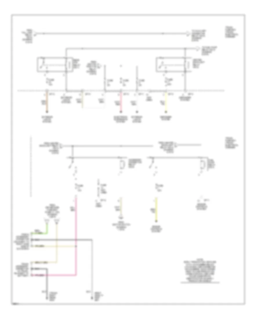
Power Distribution Wiring Diagram (4 of 6) for Jaguar XK8 1997
List of elements for Power Distribution Wiring Diagram (4 of 6) for Jaguar XK8 1997:
53
(left hand "a" post) g202
(not used)
Air conditioning system
Auxiliary positive relay
Body processor module
Cellular phones system
Cigar lighter
Computer data lines system
Cruise control system
Defogger system
Door locks system
Driver side fuse box (fascia, driver side)
Electronic power steering system
Fc20
Fc21
Fc5
Fc6
Fc90
Fc93
From auxiliary positive relay (diagram 4 of 6)
From fuse 6 t (diagram 4 of 6)
From ignition positive relay (diagram 3 of 6)
From ignition switch (diagram 1 of 6)
From tunnel stud connector (diagram 1 of 6)
Fuse
Fuse 10 (not used)
Fuse 10a
Fuse 13 (not used)
Fuse 15a
Fuse 20a
Fuse 25a
Fuse 3 (not used)
Fuse 5a
Instrument cluster system
Interior lights system
Interior lights, door locks, & power windows systems
Interior lights, mirrors, door locks, anti-theft & power windows systems
Memory systems
Memory, mirrors & power windows systems
Mirrors & seats systems
Mirrors system
Note: early production vehicles with vin numbers below (vin 003300) use connector pin numbers, which differ from volume production models shown. use wire color code for pin identification on early production models.
Passenger side fuse box (fascia, passenger side)
Passenger side fuse box (fascia, passenger side)
Power windows system
Seats system
Sound systems
To driver side fuse box (diagram 3 of 6)
To fuse 10 (diagram 4 of 6)
To fuse 7 (diagram 4 of 6)
Transit isolation device & power windows system
Transmissions system
W/3-way seat
Power Distribution Wiring Diagram (5 of 6) for Jaguar XK8 1997
List of elements for Power Distribution Wiring Diagram (5 of 6) for Jaguar XK8 1997:
34
(exterior lights system)
(not used)
Bt10
Bt11
Bt12
Bt13
Bt64
Convertible
Coupe
Door locks & anti-theft systems
Electronic suspension system
Exterior lights system
Exterior lights, mirrors & power tops systems
From fuse 16 (diagram 5 of 6)
From high power protection module (diagram 1 of 6)
From inertia switch diagram (1 of 6)
Fuse (not used)
Fuse 10a
Fuse 20a
Fuse 20a (conv.)
Fuse 40a (conv.)
Fuse 5a
Ignition positive relay
Note: early production vehicles with vin numbers below (vin 003300) use connector pin numbers, which differ from volume production models shown. use wire color code for pin identification on early production models.
Power antenna system
Power tops system
Red/ pnk
Sound systems
Stop lamp relay (no.5)
Tail lamp relay (no.3)
To fuse 3 diagram (6 of 6)
To fuse no. 18 (diagram 5 of 6)
To rear fog relay (no.1) (diagram 6 of 6)
Trunk fuse box (trunk, electrical carrier)
Power Distribution Wiring Diagram (6 of 6) for Jaguar XK8 1997
List of elements for Power Distribution Wiring Diagram (6 of 6) for Jaguar XK8 1997:
37
(defogger system)
(engine controls system)
(exterior lights system)
(no.5) (diagram 5 of 6)
(not used)
(right hand "a" post g201
(trunk, right rear) g405
Accessory connector relay (no.6)
Bt10
Bt11
Bt12
Bt13
Defogger system
Electronic suspension system
Engine controls system
Exterior lights system
Fascia accessory connector (adjacent to right hand side of glove box)
From driver side fuse box (fuse 17, 10a) (diagram 3 of 6)
From heated backlight relay x (no.2) (diagram 6 of 6)
From heated backlight y relay (no.2) (diagram 6 of 6)
From ignition positive u
From ignition switch (diagram 1 of 6)
From tail lamp relay w
Fuel pump relay (no.4)
Fuse (not used)
Fuse 10a
Fuse 20a
Fuse 25a
Fuse 5a
Heated backlight relay (no.2)
Note: early production vehicles with vin numbers below (vin 003300) use connector pin numbers, which differ from volume production models shown. use wire color code for pin identification on early production models.
Rear fog relay (no.1)
Relay (diagram 5 of 6)
To auxiliary connector relay (no.6) (diagram 6 of 6)
To fuel pump relay (no.4) (diagram 6 of 6)
Trunk accessory connector (in trunk, adjacent to battery)
Trunk fuse box (trunk, electrical carrier)
POWER DOOR LOCKS
Power Door Lock Wiring Diagram (1 of 2) for Jaguar XK8 1997
List of elements for Power Door Lock Wiring Diagram (1 of 2) for Jaguar XK8 1997:
39
(adjacent to left hand fascia fuse box) inertia switch
(left hand "a" post) g202
(not used)
(right hand "a" post) g201
Acc
Body processor module (passenger side fascia, airbag bracket)
Data +
Data -
Door locking relay
Dp10
Dp11
Driver door lock actuator (inside driver's door)
Driver side fuse box (driver side fascia)
Exterior handle
Fc5
Fuse 15a
Fuse 25a
G201 (right hand "a" post)
G202 (left hand "a" post)
Hot at all times
Ignition switch
Input
Key in
Lock status
Logic gnd
Nca
Not-in-park microswitch (gear selector assembly)
Note; early production vehicles with vin numbers below (vin 003300) use connector pin numbers, which differ from volume production numbers shown. use wire color code for pin identification on early production models.
Off
Output
Passenger door control module (inside passenger's door)
Passenger door lock actuator (inside passenger's door)
Passenger door lock switch (inside passenger's door)
Passenger door switch (inside passenger's door)
Pwr gnd
Right fascia relays (right side of i/p)
Run
Start
Valet switch (driver knee bolster)
Power Door Lock Wiring Diagram (2 of 2) for Jaguar XK8 1997
List of elements for Power Door Lock Wiring Diagram (2 of 2) for Jaguar XK8 1997:
42
(adjacent to battery) g401
(left hand "a" post) g202
(roof, adjacent to backlight) g909
Braid
Bt13
Bt40
Bt41
Computer data lines system
Convertible
Coupe
Data +
Data -
Dd10
Dd11
Driver door control module (inside driver's door)
Driver door lock switches (inside driver's door)
Driver door switch (inside driver's door)
Exterior handle
Fc20
Fc21
Fuse 10a
Fuse 20a
Fuse 25a
Fuse 5a
Gnd
Hot at all times
Input
Key barrel
Key fob antenna (top of backlight)
Lock
Logic gnd
Note: early production convertible vehicles (below vin 003300)- antenna shield is grounded to g909.
Note; early production vehicles with vin numbers below (vin 003300) use connector pin numbers, which differ from volume production numbers shown. use wire color code for pin identification on early production models.
Output
Passenger side fuse box (passenger side fascia)
Pwr gnd
Rh20
Rh7
Security & locking control module (right side of trunk, in electrical carrier)
Tan
Trunk fuse box (trunk, electrical carrier)
Unlock
POWER MIRRORS
Electrochromic Mirrors Wiring Diagram for Jaguar XK8 1997
List of elements for Electrochromic Mirrors Wiring Diagram for Jaguar XK8 1997:
41
"a" post) g202
(adjacent to battery) g401
(left hand "a" post) g202
(right hand rear quarter) g905
Bt13
Column switch gear (steering column)
Computer data lines system
Conv top dn
Convertible
Convertible top down switch (right hand operating cylinder)
Coupe
Dd8
Dip
Dp8
Driver door mirror (electrochromic) (driver door)
Driver side fuse box (driver side fascia)
Early production vehicles
Exterior lights system (reverse lights)
Fc25
Fc5
Fuse 5a
Gnd
Headlights system
Hot at all times
Hot in run & start
Interior rear view mirror (electrochromic) (forward of roof console)
Lighting stalk
Major instrument pack
Note: early production vehicles with vin numbers below (vin 003300) use connector pin numbers, which differ from volume production numbers shown. use wire color code for pin identification on early production vehicles.
Note: lighting stalk as shown vaild only for early production vehicles below (vin 003300).
Off
Output
Passenger door mirror (electrochromic) (passenger door)
Reverse gear
Sc2
Scp data +
Scp data -
Security & locking control module (trunk electrical carrier)
Side
Side lps on
Trunk fuse box (trunk electrical carrier)
Fold-back Mirrors Wiring Diagram for Jaguar XK8 1997
List of elements for Fold-back Mirrors Wiring Diagram for Jaguar XK8 1997:
46
(left hand "a" post) g202
(left hand seat) g300
(right hand seat) g301
Computer data lines system
Dd10
Dd11
Dd17
Dd8
Direction
Down
Dp8
Driver door control module (inside driver's door)
Driver door mirror (electrochromic) (driver door)
Driver door switch pack
Driver seat control module (below seat cushion)
Driver side fuse box (driver side fascia)
Fc21
Fc5
Fc6
Fold- back
Fuse 20a
Fuse 25a
Fuse 5a
Gnd
Hot at all times
Input
Left
Left horizontal
Left vertical
Mirror joystick
Note: early production vehicles with vin numbers below (vin 003300) use connector pin numbers, which differ from volume production numbers shown. use wire color code for pin identification on early production vehicles.
Output
Passenger door mirror (electrochromic) (passenger door)
Passenger seat control module (below seat cushion)
Passenger side fuse box (passenger side fascia)
Red
Right
Right horizontal
Right vertical
Scp data +
Scp data -
Sd3
Sd5
Slip mechanism
Sp3
Sp5
POWER SEATS
Passenger's Power Seat Wiring Diagram for Jaguar XK8 1997
List of elements for Passenger's Power Seat Wiring Diagram for Jaguar XK8 1997:
67
(0) off
(i)
(iii) start
(left hand "a" post) g202
(not used)
(right hand seat) g301
1996 vftc c
3-way movement
Acc run (ii)
Aft
Body processor module (passenger side fascia, on airbag bracket)
Center console switch pack
Computer data lines system
Deflate
Driver side fuse box (driver side fascia)
Fc20
Fc21
Fc5
Fore
Fuse 15a
Fuse 20a
Fuse 5a
Heater
Hot at all times
Ignition switch
Inflate
Input
Left hand "a" post) g202
Logic gnd
Lower
Lumbar
Nca
Not used
Note: early production vehicles below (vin 003300) connector sp4, pin 3.
Note: early production vehicles with vin numbers below (vin 003300) use connector pin numbers, which differ from volume production numbers shown. use wire color code for pin identification on early production vehicles.
Output
Passenger seat control module (below seat cushion)
Passenger seat cushion (seat cushion)
Passenger seat lumbar pump (seat back)
Passenger seat motors (below seat cushion)
Passenger seat switch pack
Passenger side fuse box (passenger side fascia)
Passenger squab (seat squab)
Power gnd
Pressure switch
Raise
Recline
Red
Scp data +
Scp data -
Seat
Seat belt switch wiring (not used)
Seat fore/aft
Seat front
Seat heater state
Seat heater switch
Seat raise/lower (3-way movement)
Seat rear
Solenoid valve
Sp3
Sp5
Sp7
Sp8
Sp9
Squab recline fore/aft
Start(iii)
Thermostat
POWER TOP/SUNROOF
Power Top/Sunroof Wiring Diagrams for Jaguar XK8 1997
List of elements for Power Top/Sunroof Wiring Diagrams for Jaguar XK8 1997:
61
(0) off
(adjacent to battery) g401
(iii) start
(left hand "a" post) g202
(not used)
(right hand operating cylinder)
(right hand rear quarter) g905
(top of windshield)
Acc (i)
Body processor module (passenger side fascia, on airbag bracket)
Bt10
Bt12
Bt13
Bt40
Bt41
Computer data lines system
Convertible top pump (right side of trunk)
Convertible top switch
Down
Driver side fuse box (driver side fascia)
Fc14
Fc46
Fc5
Fuse 15a
Fuse 20a
Fuse 40a
Fuse 5a
G202 (left hand "a" post)
G401 (adjacent to battery)
G405 (trunk, right rear)
Gnd
Hot at all times
Ignition switch
Inertia switch (adjacent to left hand fascia fuse box)
Input
Latch control valve (trunk, near convertible top pump)
Left quarter down relay
Left quarter light lift (rear quarter panel)
Left quarter up relay
Logic gnd
Main control valve (trunk, near convertible top pump)
Nca
Note; early production vehicles with vin numbers below (vin 003300) use connector pin numbers, which differ from volume production numbers shown. use wire color code for pin identification on early production vehicles.
Output
Pwr gnd
Right quarter down relay
Right quarter light lift (rear quarter panel)
Right quarter up relay
Run (ii)
Scp data +
Scp data -
Security & locking control module (trunk electrical carrier)
List of elements for Power Window Wiring Diagram for Jaguar XK8 1997:
39
(left hand "a" post) g202
(right hand "a" post) g201
Computer data lines system
Data +
Data -
Dd10
Dd11
Dp10
Driver door control module (inside driver's side door)
Driver door lock switches
Driver door switch pack
Driver side fuse box (driver side fascia)
Driver window lift
Fc20
Fc21
Fc5
Fuse 25a
Fuse 5a
Hot at all times
Input
Key barrel
Left window down
Left window up
Local window down
Local window up
Lock
Logic gnd
Movement sensor
Note: early production vehicles with vin numbers below (vin 003300) use connector pin numbers, which differ from volume production numbers shown. use wire color code for pin identification on early production models.
Output
Passenger door control module (inside passenger's side door)
Passenger door switch pack
Passenger side fuse box (passenger side fascia)
Passenger window lift
Pwr gnd
Right window down
Right window up
Unlock
Window lift switches
RADIO
Radio Wiring Diagrams, Base Radio for Jaguar XK8 1997
Note: early production vehicles with vin numbers below (vin 003300) use connector pin numbers, which differ from volume production numbers shown. use wire color code for pin identification on early production models.
List of elements for 4.0L, Charging Wiring Diagram for Jaguar XK8 1997:
23
(battery ground stud) g401
(right side of false bulkhead, in engine compartment) false bulkhead stud connector
1996 vftc c
250a
Battery (right side of trunk)
Bt60
Bt61
Bt80
Charge warning
Engine compartment fuse box (left front of engine compartment)
Fc26
Fuse 5 10a
Generator (right front of engine compartment)
High power protection module (in trunk, adjacent to battery)
Hot in run & start
Lf6
Major instrument pack
Note: early production vehicles with vin numbers below (vin 003300) use connector pin numbers, which differ from volume production models shown. use wire color code for pin identification on early production models.
St1
St10
St2
Starter motor (engine block)
Suppression module (forward of generator, in engine compartment)
List of elements for 4.0L, Starting Wiring Diagram for Jaguar XK8 1997:
53
(battery ground stud) g401
(left hand "a" post) g202
(not used)
1996 vftc c
250a
Acc i
An1/ st11
Battery (right side of trunk)
Body processor module (on airbag bracket, passenger side fascia)
Bt60
Bt61
Bt80
Crank input
Data
Driver side fuse box (driver side fascia)
Em10
Em11
Em20
Engine compartment fuse box (left front of engine compartment)
Engine control module (engine compartment, control module enclosure)
Engine management fuse box (engine compartment, control module enclosure)
False bulkhead stud connector (right side of false bulkhead, in engine compartment)
Fc14
Fc22
Fc5
Fuse 3 25a
Fuse 5 10a
Fuse 5 15a
Generator (right front of engine compartment)
High power protection module (in trunk, adjacent to battery)
Hot at all times
Hot in run & start
Ignition switch
Input
Lf6
Logig gnd
Nca
Neutral switch (gear selector assembly)
Note: early production vehicles with vin numbers below (vin 003300) use connector pin numbers, which differ from volume production models shown. use wire color code for pin identification on early production models.
Off
Output
Pwr gnd
Right brake booster enclosure relays
Run ii
Security data
St1
St10
St2
St3
Start iii
Starter motor (engine block)
Starter relay
Suppression module (forward of generator, in engine compartment)
SUPPLEMENTAL RESTRAINTS
Supplemental Restraint Wiring Diagram for Jaguar XK8 1997
List of elements for A/T Wiring Diagram for Jaguar XK8 1997:
69
(left hand "a" post) g202
10-11
19-20
24-25
38-41
46-50
56-81
87-88
Battery
Can data +
Can data -
Computer data lines system
D-4 switch
D-4 switch (rear gear shift assem)
Driver side fuse box (fascia, driver side)
Em20
Enclosure) em10
Engine compartment fuse box (left front of eng compt)
Engine control module (engine compartment, control module p, n sig
Engine management fuse box (engine compartment, control module enclosure)
Fc5
Fluid temp sens
Fluid temp sensor
Fuse 10a
Fuse 5a
G104 (engine compartment, left hand enclosure)
G202 (left hand "a" post)
Gear selector module (front of gear selector assembly)
Ground
Hot at all times
Hot in run or start
Ignition
Interior lights system
Kickdown switch
Kickdown switch (below accelerator pedal)
Lfb
Mode switch
Nca
Note: early production vehicles with vin numbers below (vin 003300) use connector pin numbers, which differ from volume production models shown. use wire color code for pin identification on early production models.
Ouput spd sen
Output spd sen
Output speed sensor
P,n
Press reg 1
Press reg 2
Press reg 3
Press reg 4
Press reg 5
Press reg comm
Red
Red/pnk
Regulaltor valves
Rot sw l1
Rot sw l2
Rot sw l3
Rot sw l4
Shield
Sol vlv 1
Sol vlv 2
Sol vlv 3
Sol vlvs comm
Solenoid valves
Sprt mode sw
Sw common grd
Transmission
Transmission control module (in eng compt control module enclosure)
Transmission rotary switch
Turbine spd sen
Turbine speed sensor
TRUNK, TAILGATE, FUEL DOOR
Fuel Door Release Wiring Diagram for Jaguar XK8 1997
List of elements for Warning System Wiring Diagrams for Jaguar XK8 1997:
27
0utput
(0) off
(i) acc
(ii) run
(left hand "a" post) g202
Audible warnings: direction indicators hazard warning sidelamps on valet mode warning gear selector in park memory chime convertible top movement (convertible vehicles) key-in-ignition switch/ driver door ajar seat belt disconnected
Body processor module (passenger side fascia, on airbag bracket)
Column switchgear
Computer data lines system
Data line inputs: direction indicators; hazard warning; sidelamps valet switch; trunk release memory systems convertible top movement key-in-ignition switch/ driver door switch not-in-park switch seat belt switch
List of elements for Wiper/Washer Wiring Diagram for Jaguar XK8 1997:
54
(engine compartment, forward of left hand hood catch) g104
(engine compartment, forward of left hand hood catch) g104
(i) acc
(ii) run
(left hand "a" post) g202
(not used)
(right hand headlamp) g107
Body processor module (passenger side fascia, on airbag bracket)
Column switch gear
Delay
Dip
Driver side fuse box (driver side fascia)
Engine compartment fuse box (left front of engine compartment)
Fast
Fast wipe
Fc14
Fc5
Fc6
Flick wipe
Fluid level
Fuse 3 30a
Fuse 5 15a
Fuse 7 15a
Fuse 7 30a
Hot at all times
Ignition nca switch
Input
Intermittent wipe
Left brake booster enclosure relays (left rear corner of engine compartment)
Lf6
Lighting stalk
Logic gnd
Note: early production vehicles with vin numbers below (vin 003300) use connector pin numbrers, which differ from volume production numbers shown. use wire color code for pin identification on early production models.
Off
Off (0)
Ohms
Output
Park switch
Power gnd
Power wash pump (left front fender)
Power wash relay (no.4)
Red
Sc1
Sc2
Side
Slow
Slow wipe
Start (iii)
Wash
Wash/wipe stalk
Windshield wash pump & fluid level sensor (left front fender)
Wiper fast/ slow relay
Wiper motor (base of windshield, behind air intake plenum)
We use cookies to enhance your browsing experience, serve
personalized ads or content, and analyze our traffic. By clicking "Accept All",
you consent to our use of cookies. Privacy Policy