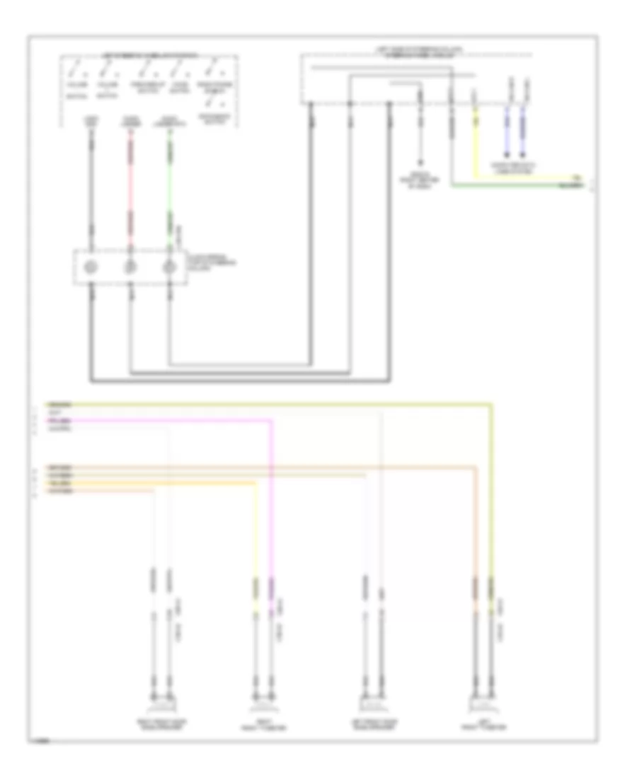
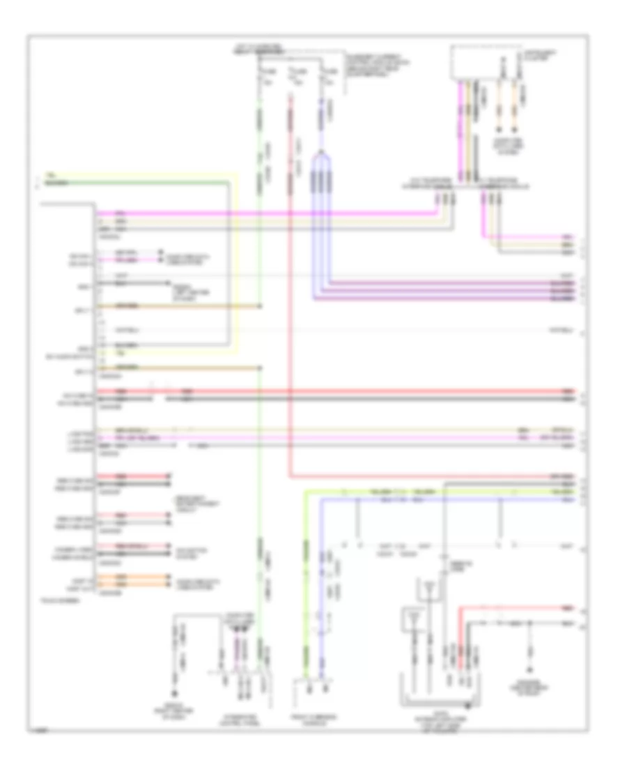
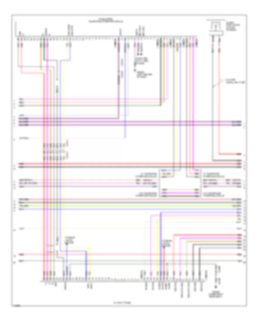
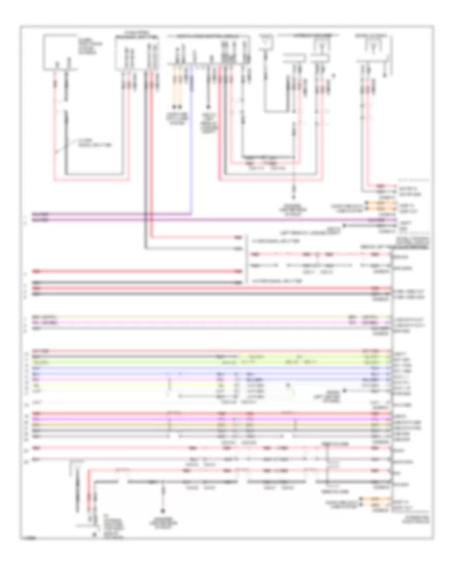
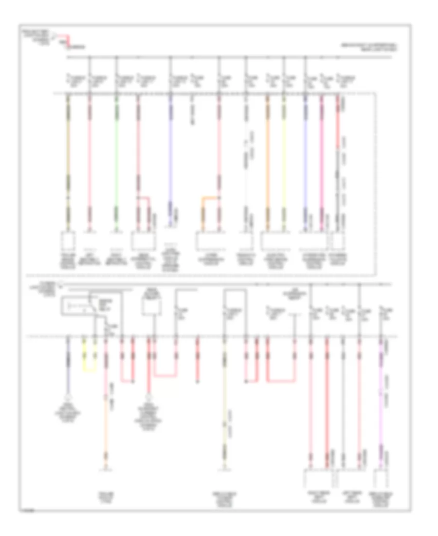
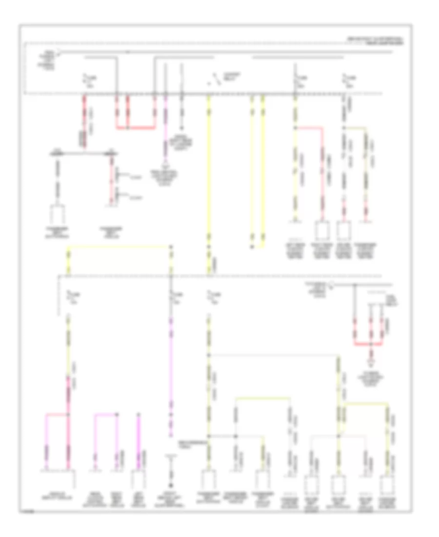
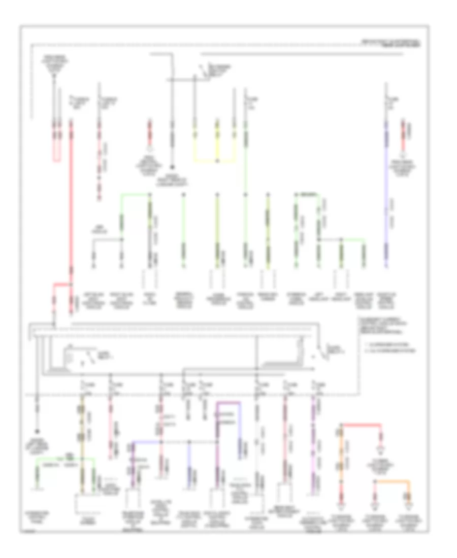
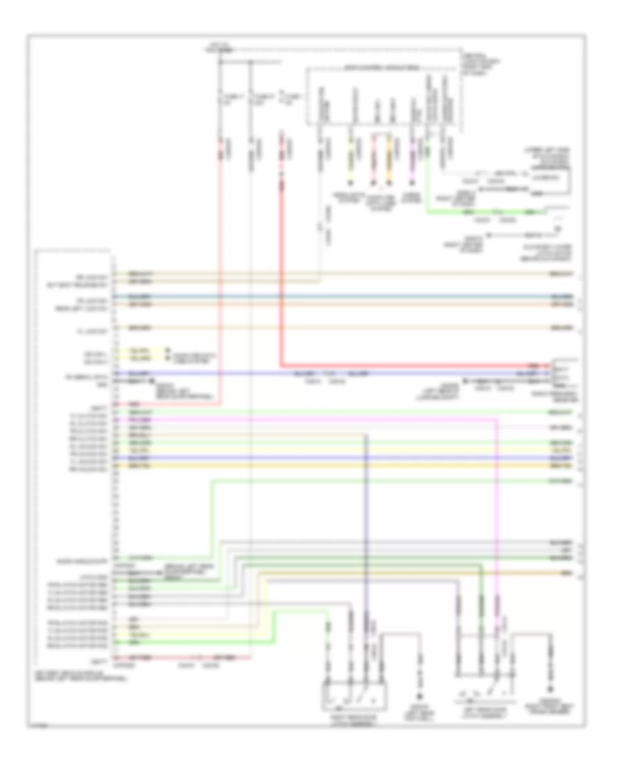
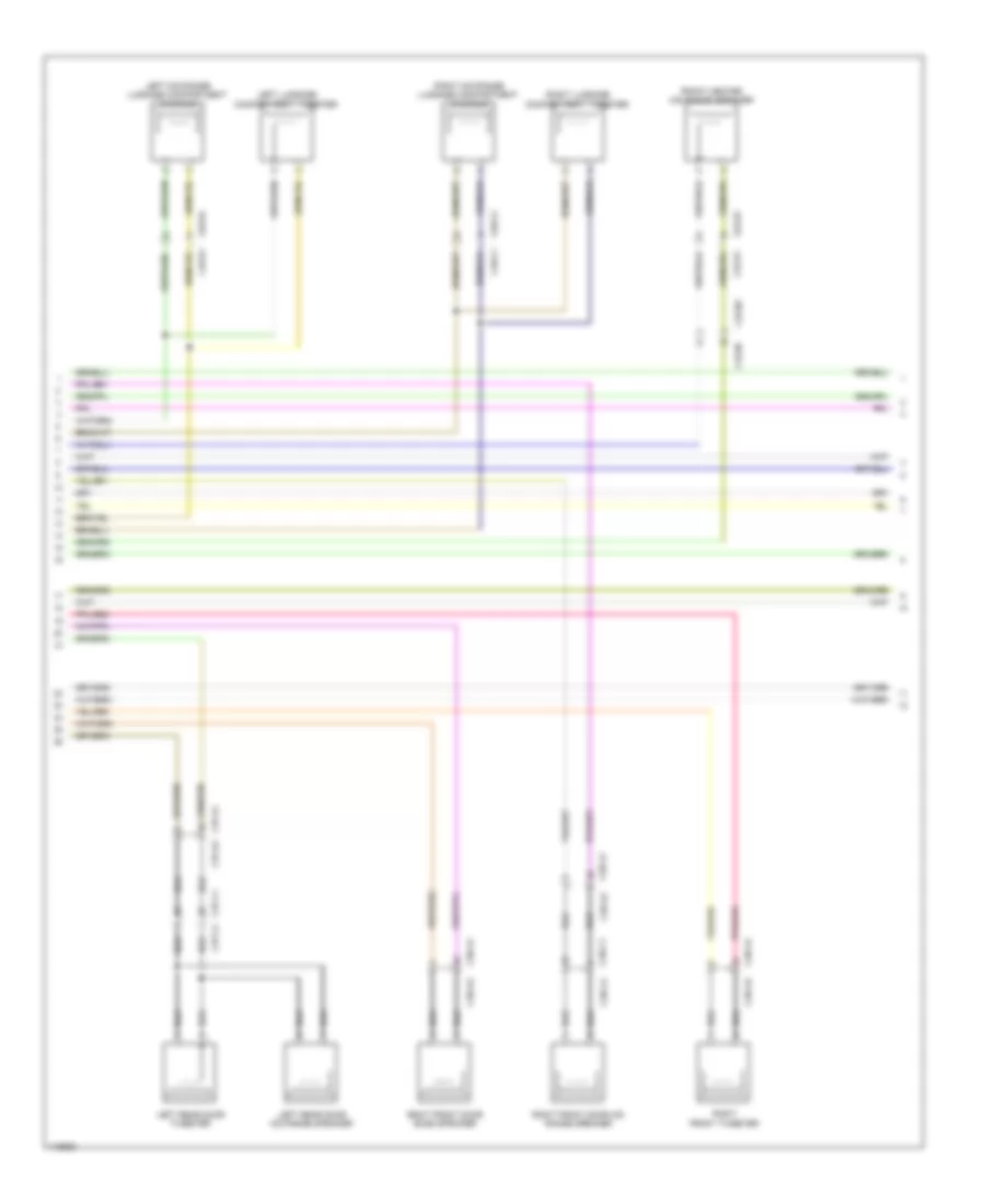
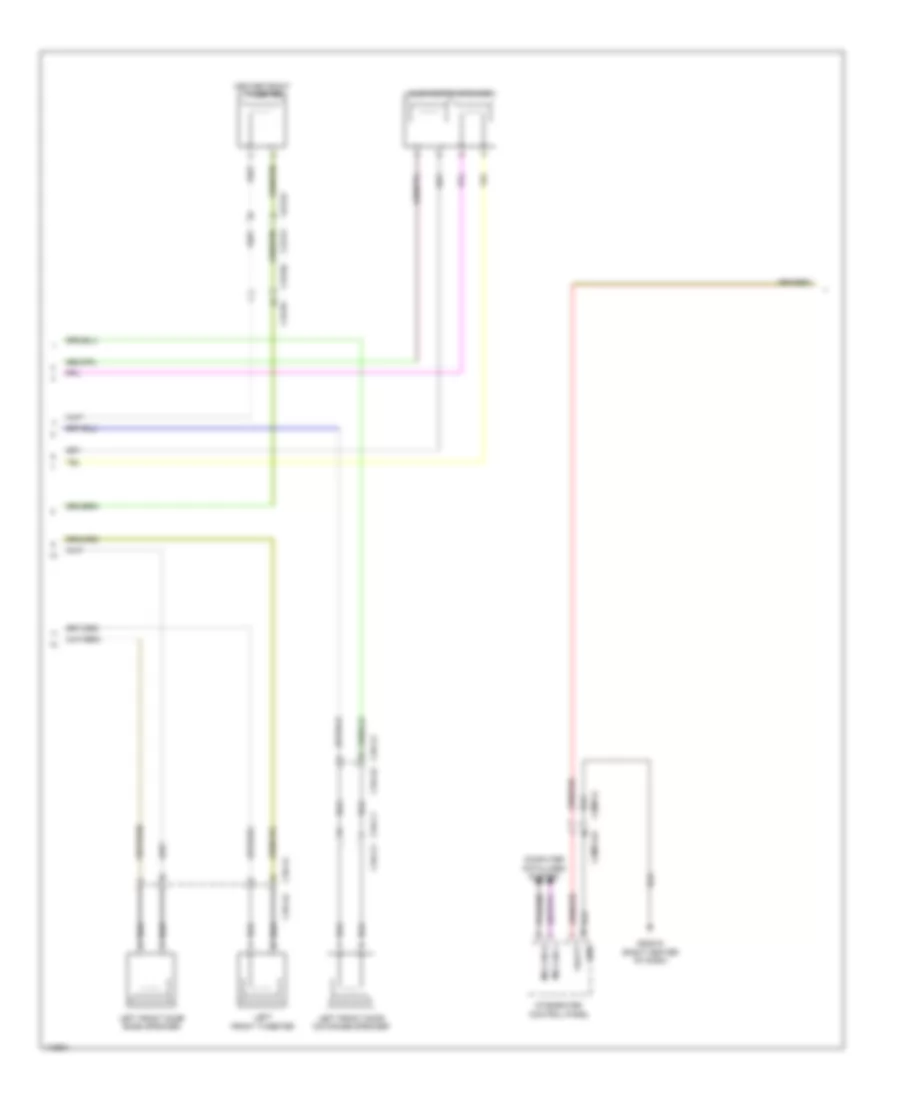
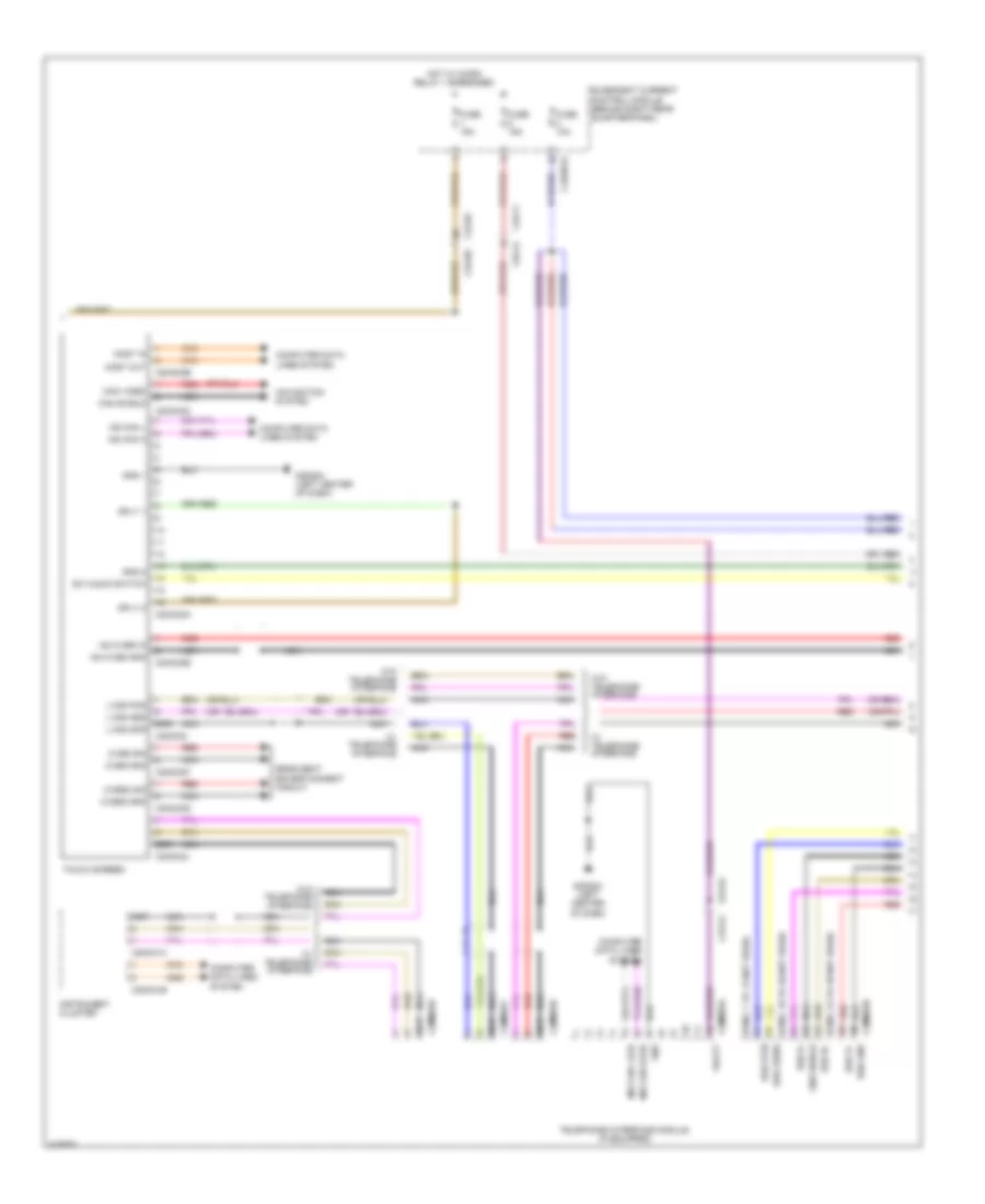
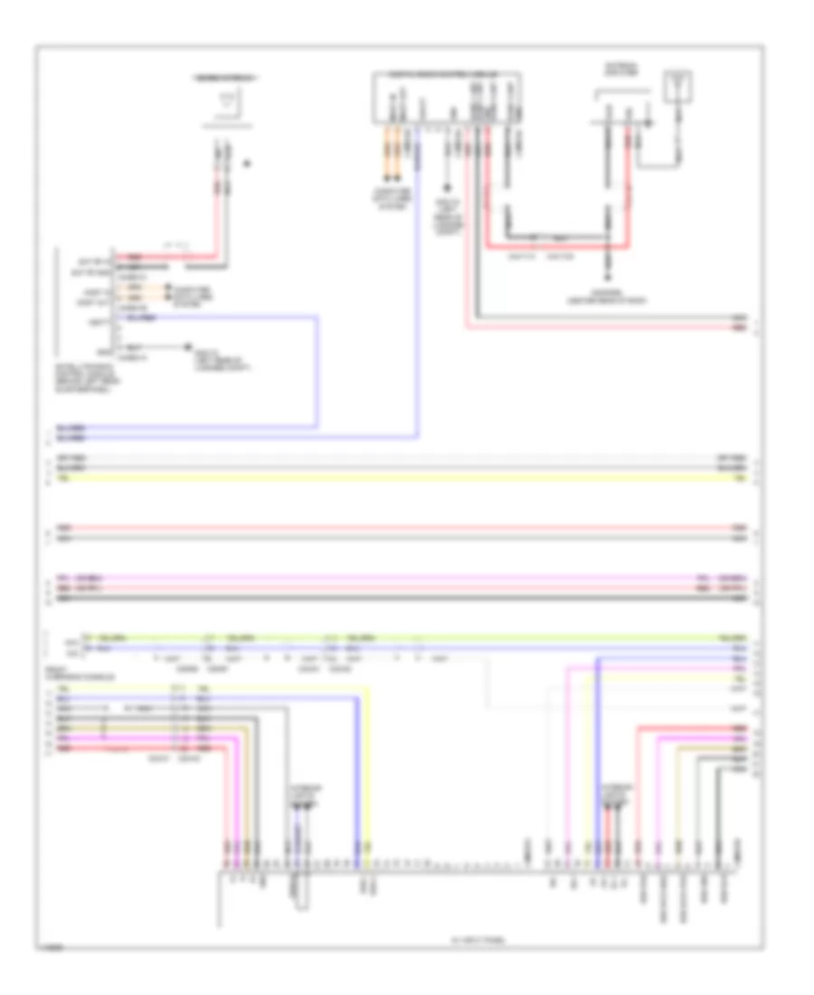
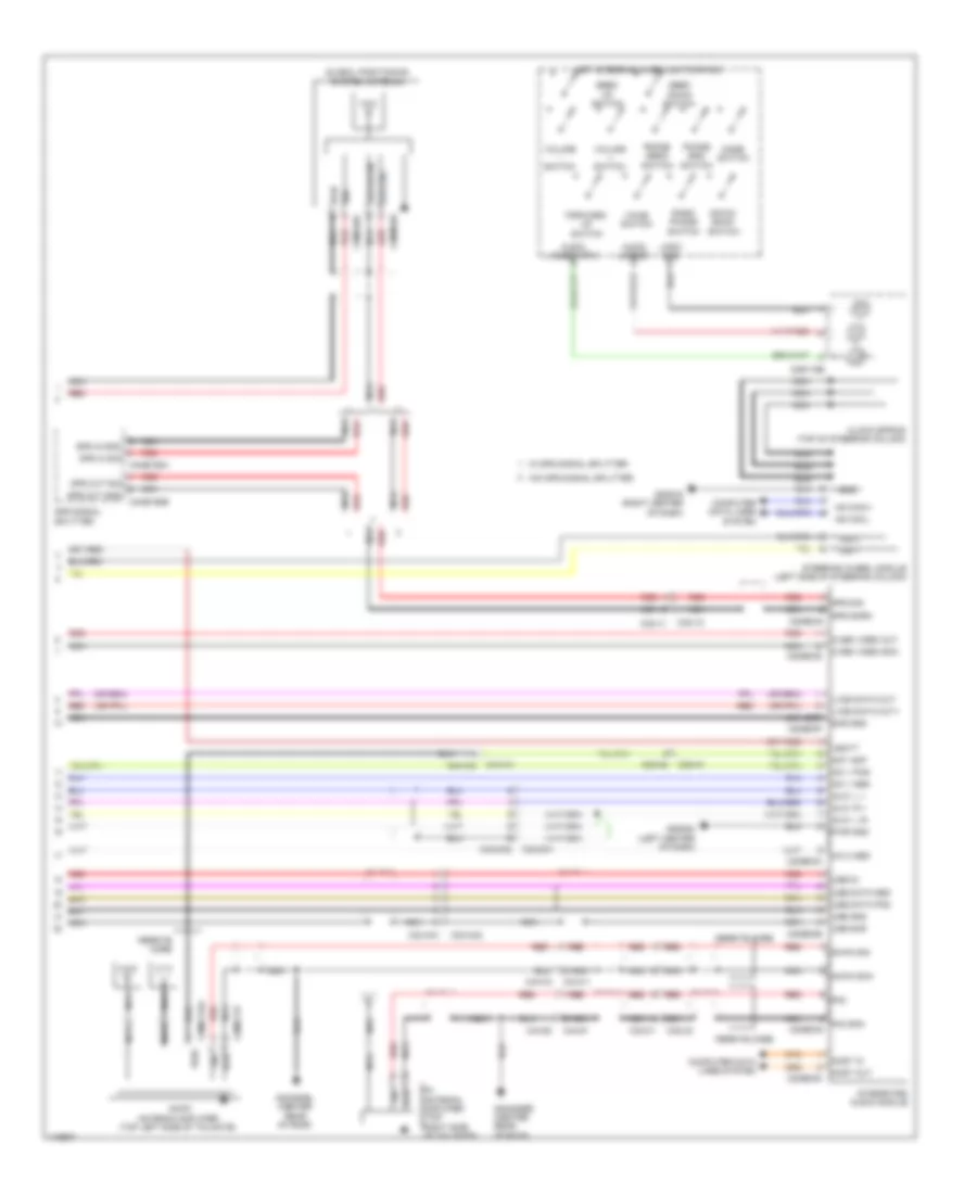
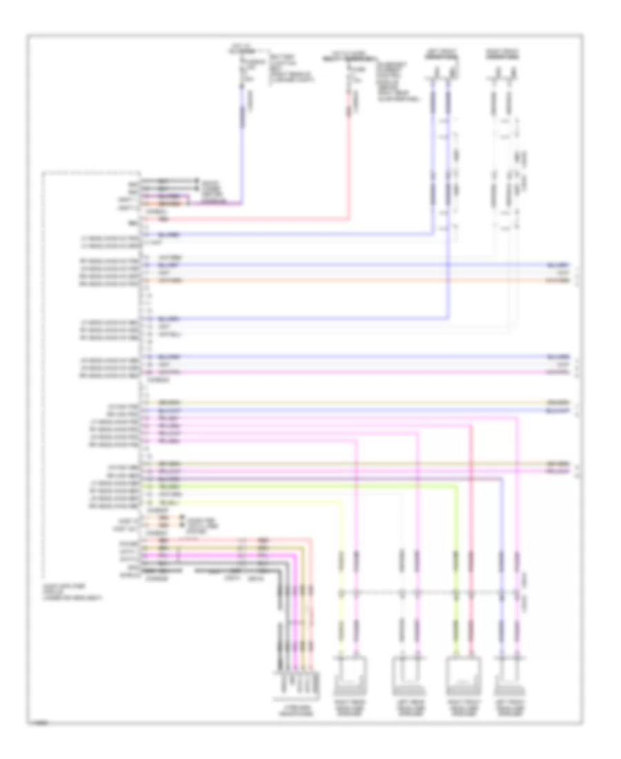
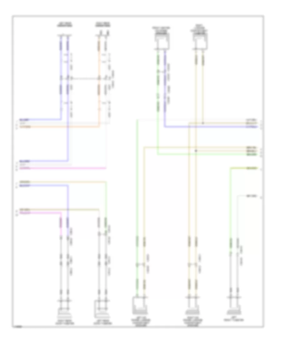
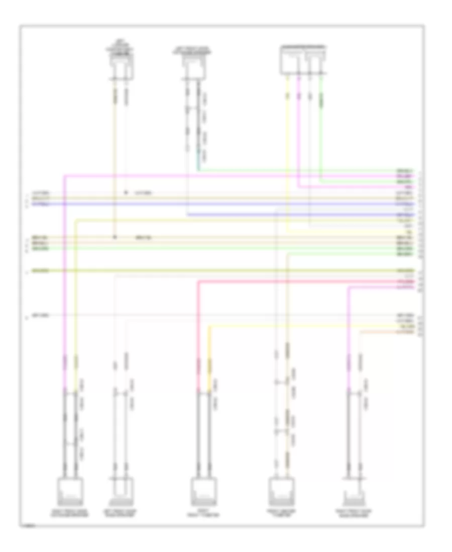
Diagram sections — 33 (176 total)
AIR CONDITIONING ANTI-LOCK BRAKES ANTI-THEFT BODY CONTROL MODULES COMPUTER DATA LINES COOLING FAN CRUISE CONTROL DEFOGGERS ELECTRONIC POWER STEERING ELECTRONIC SUSPENSION ENGINE PERFORMANCE EXTERIOR LIGHTS GROUND DISTRIBUTION HEADLIGHTS HORN INSTRUMENT CLUSTER INTERIOR LIGHTS MEMORY SYSTEMS NAVIGATION POWER DISTRIBUTION POWER DOOR LOCKS POWER MIRRORS POWER SEATS POWER TOP/SUNROOF POWER WINDOWS RADIO SHIFT INTERLOCK STARTING/CHARGING SUPPLEMENTAL RESTRAINTS TRANSMISSION TRUNK, TAILGATE, FUEL DOOR WARNING SYSTEMS WIPER/WASHER
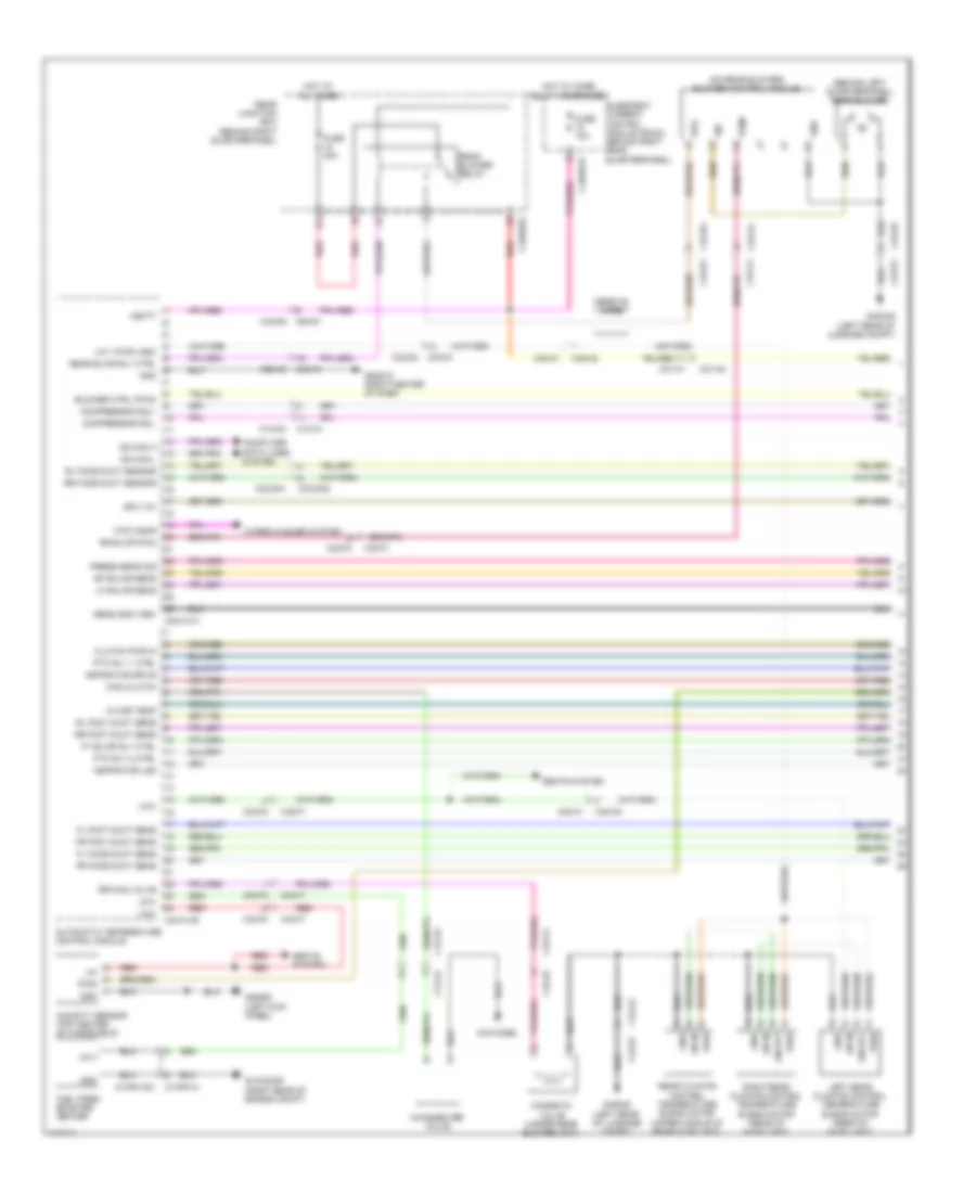
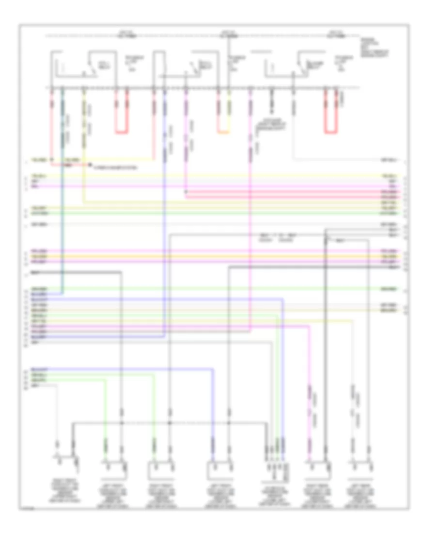
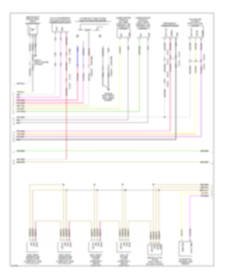
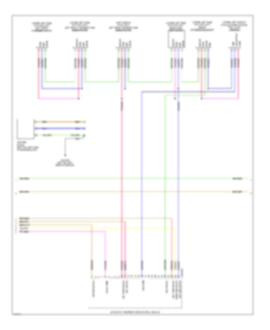
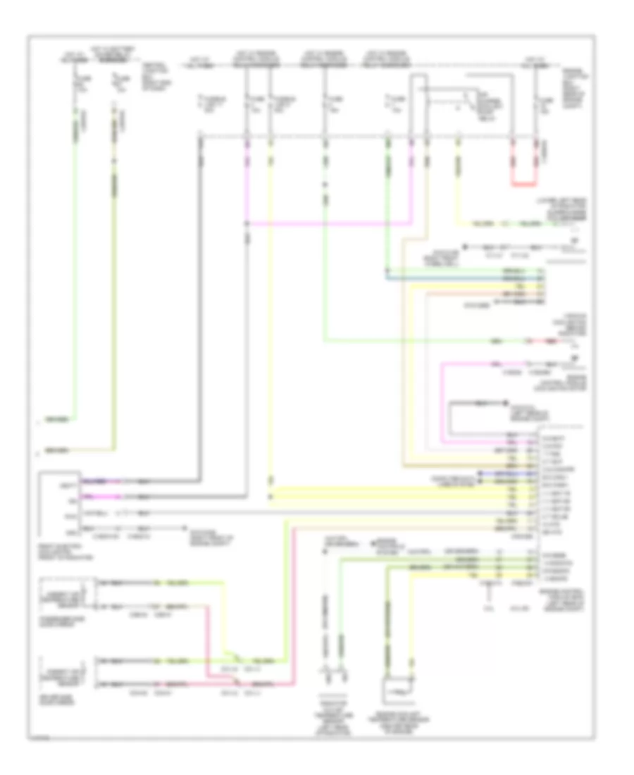
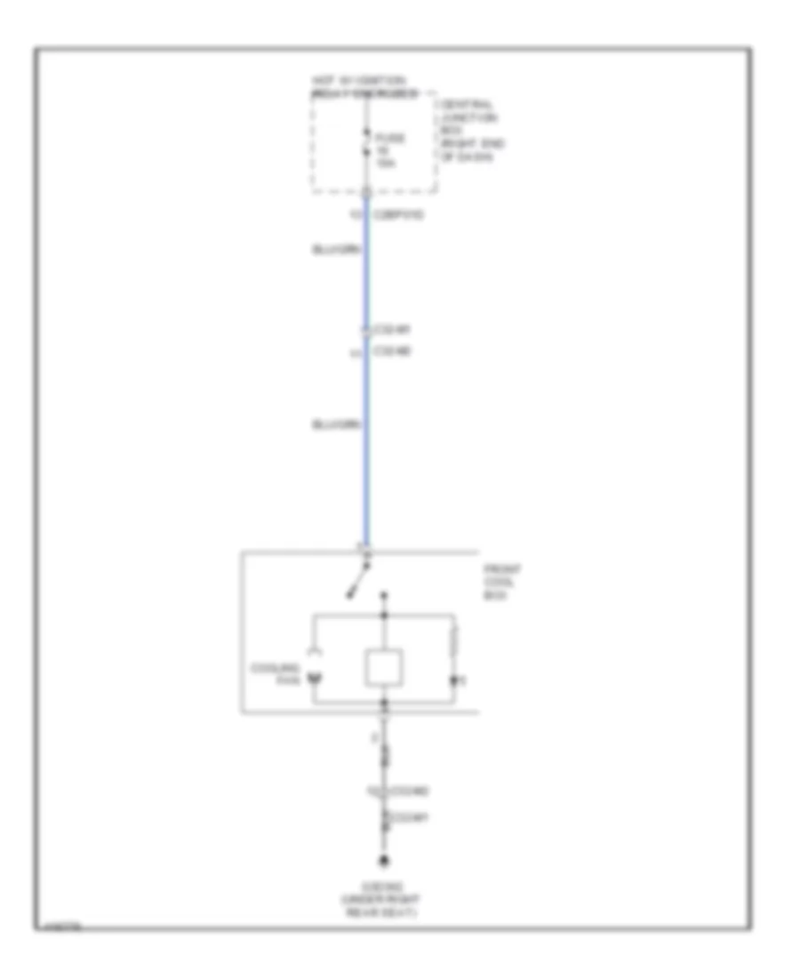
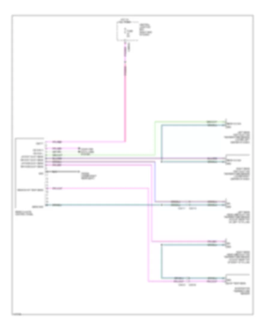
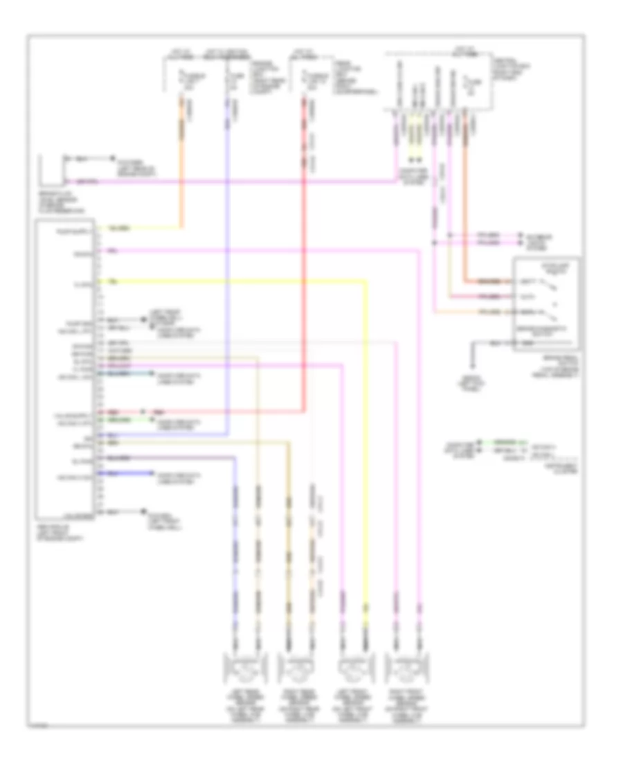
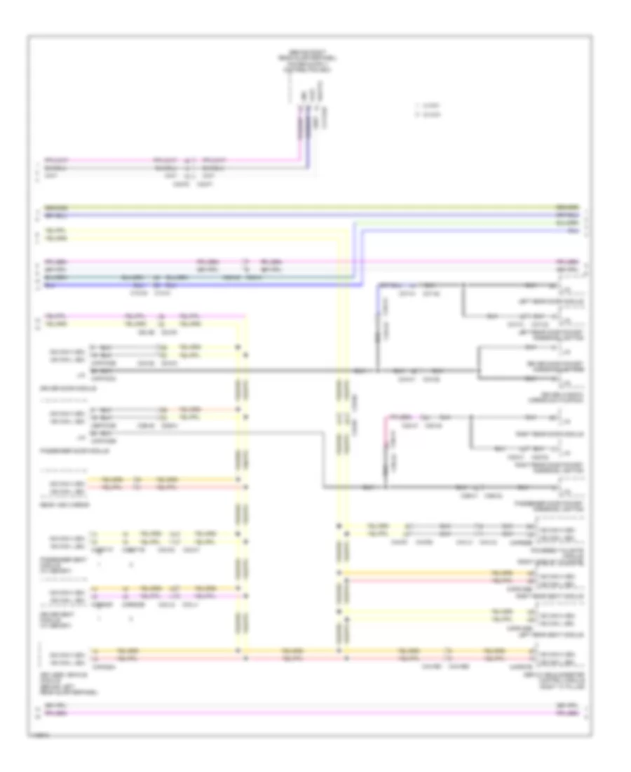
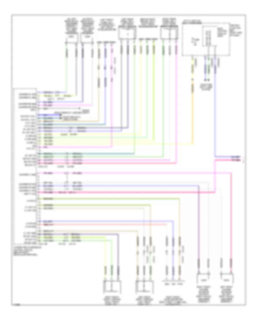
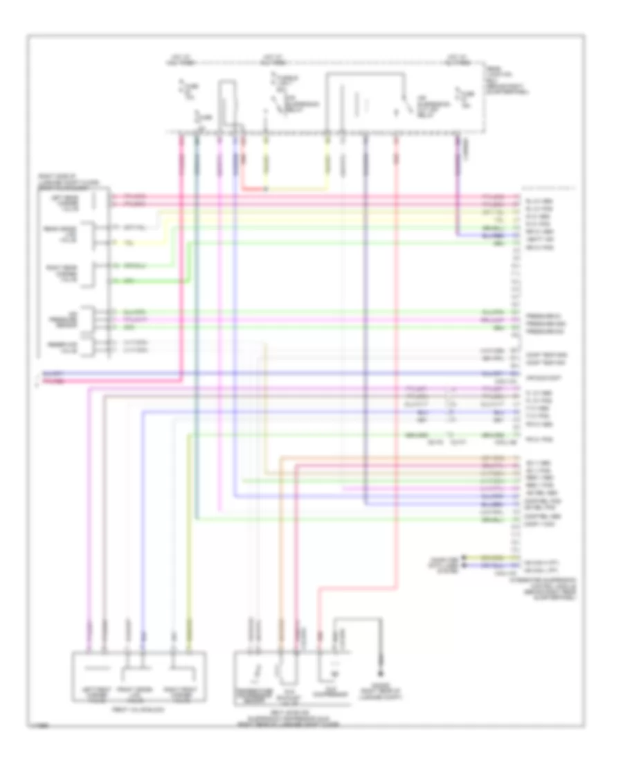
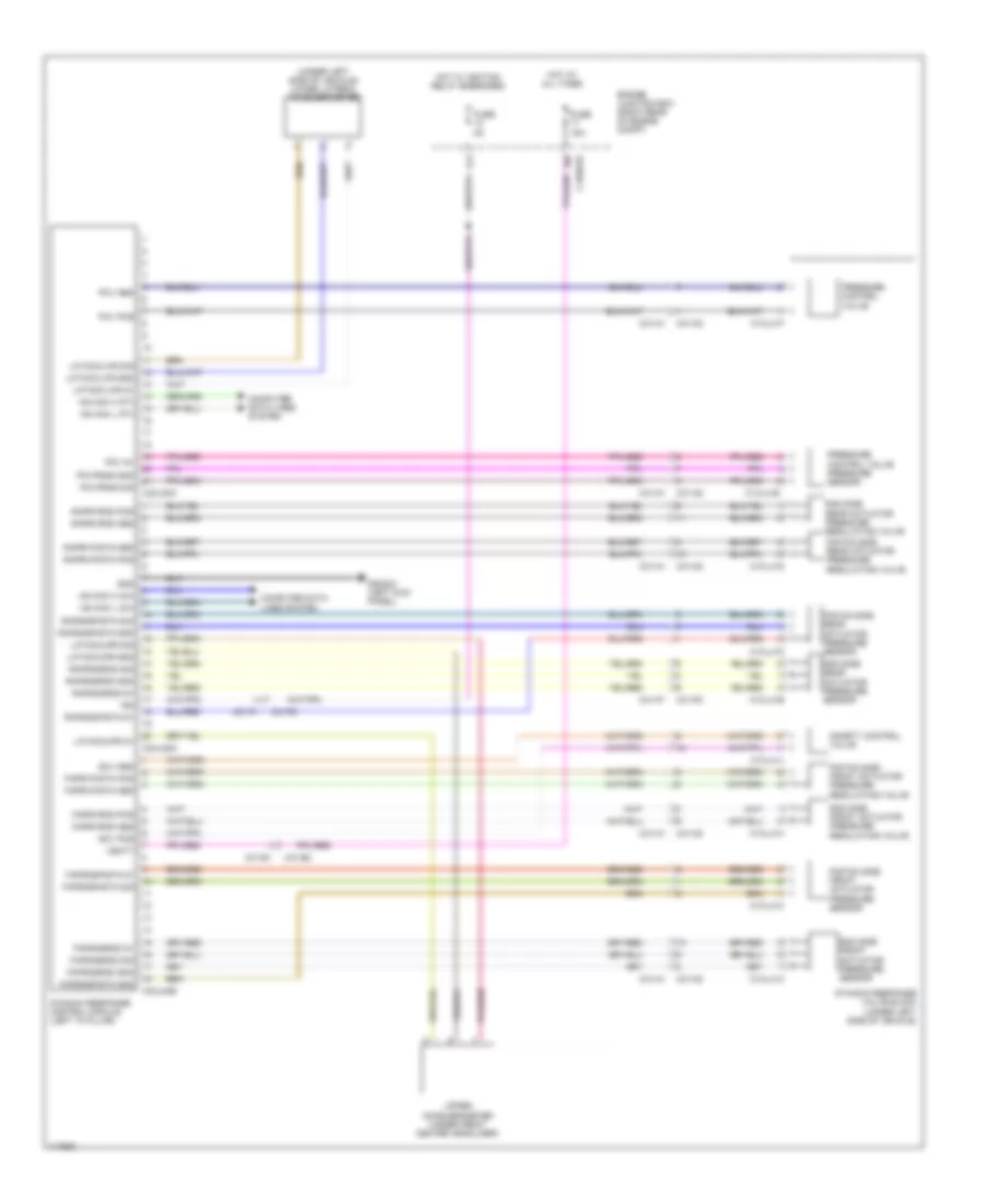
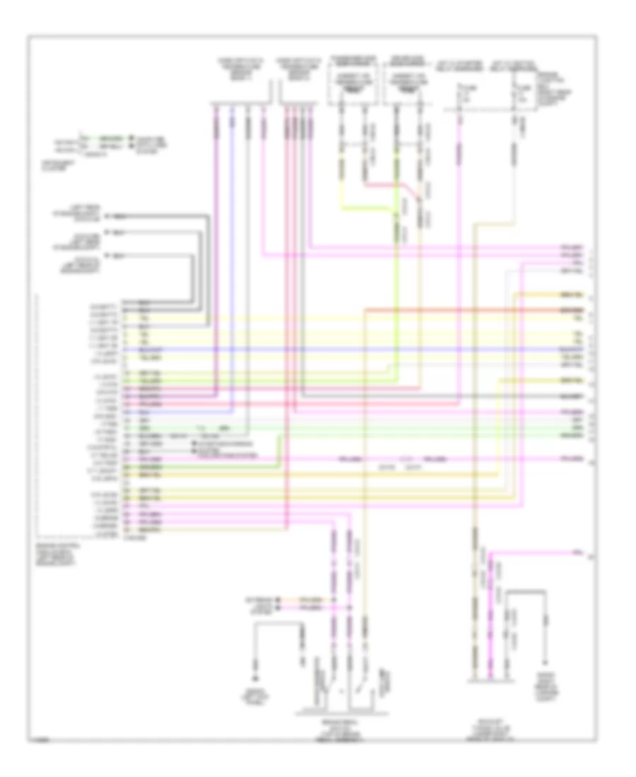
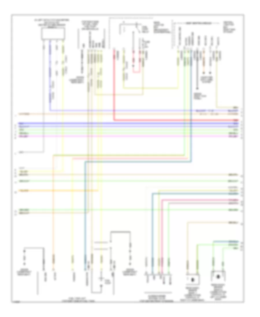
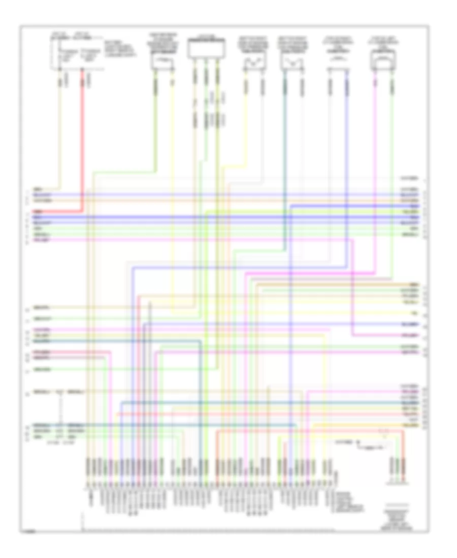
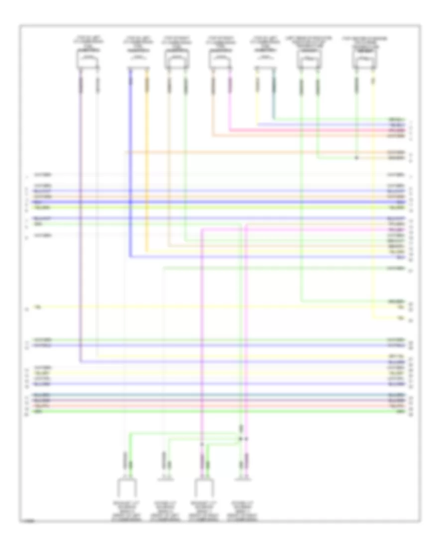
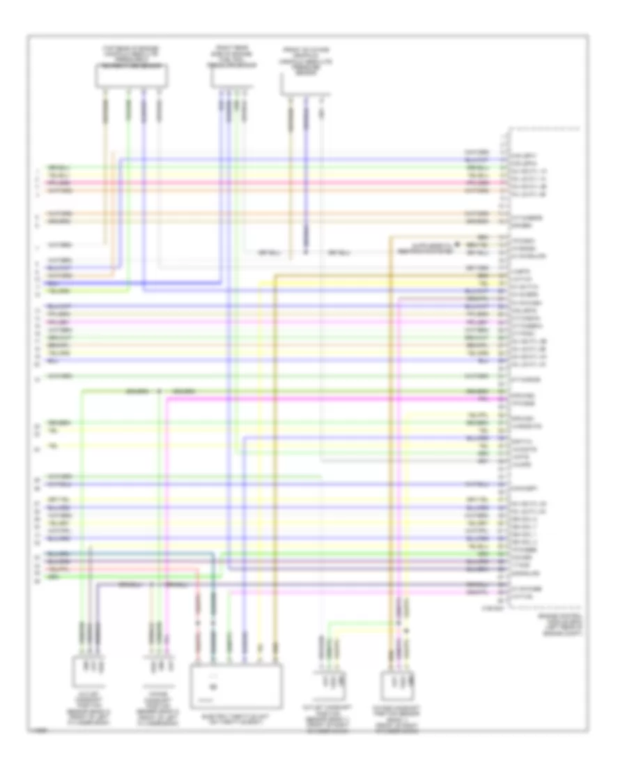
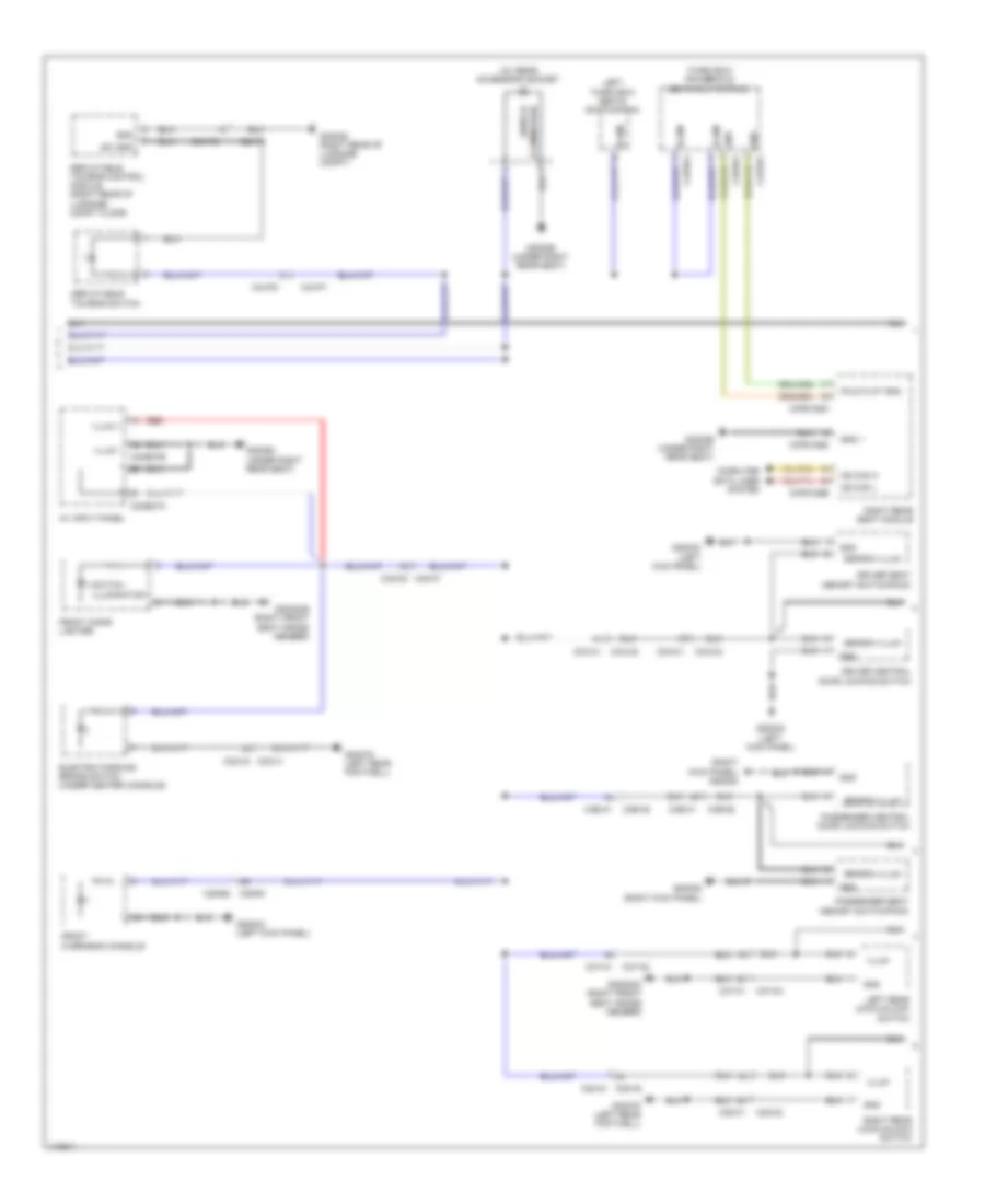
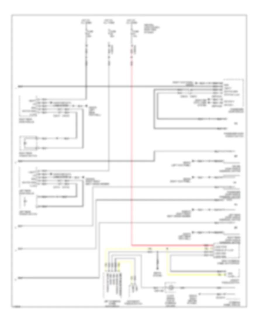
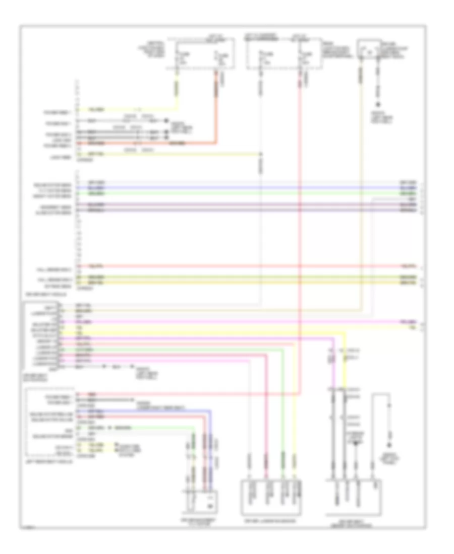
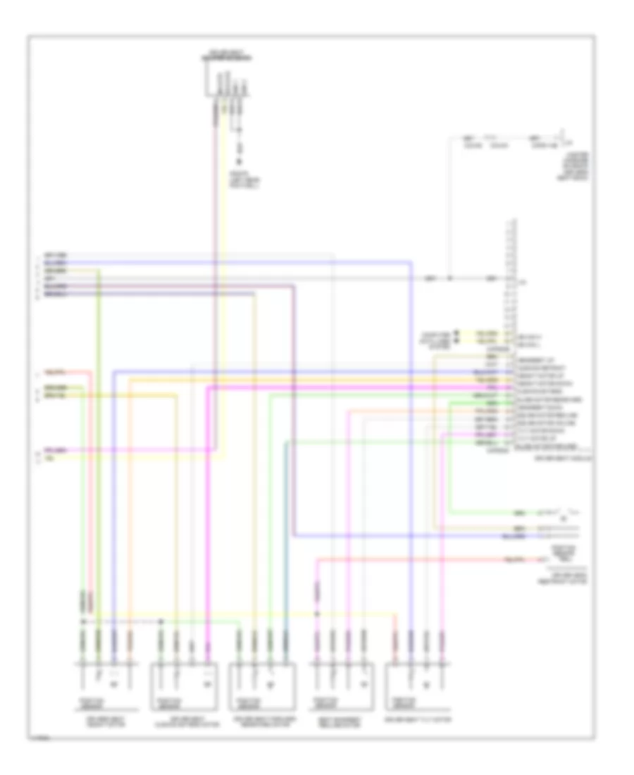
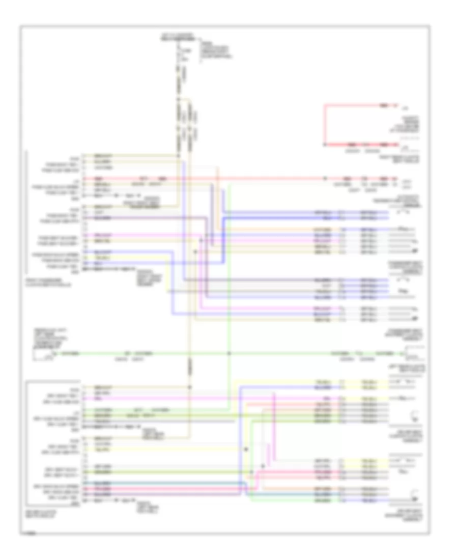
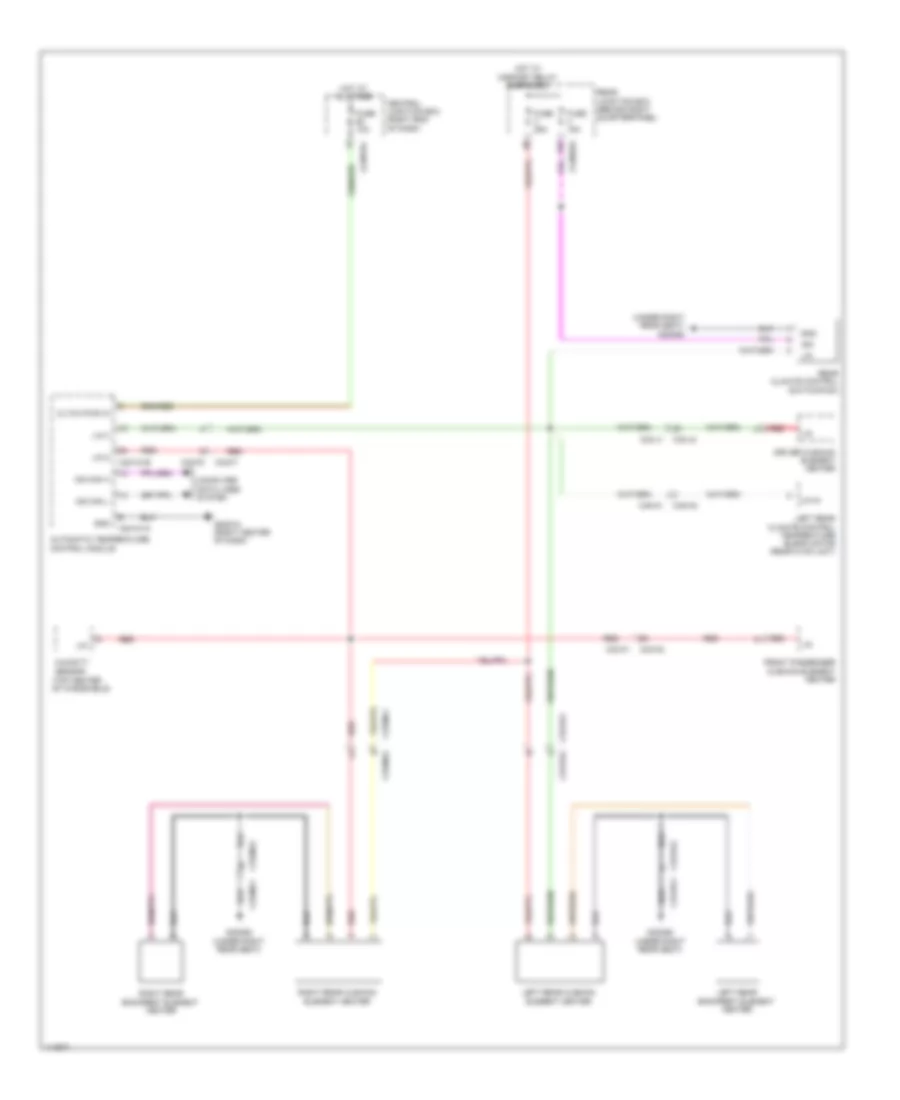
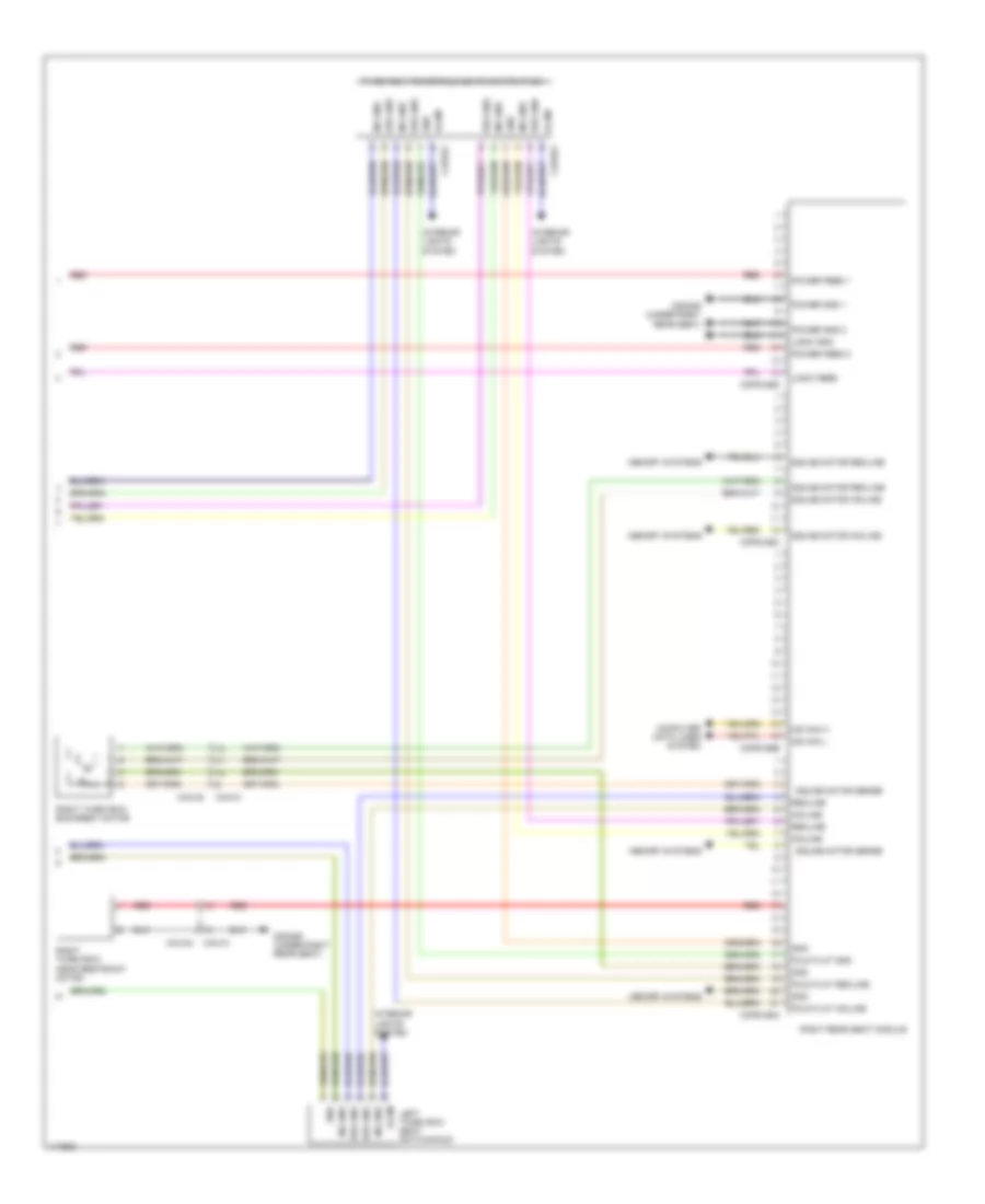
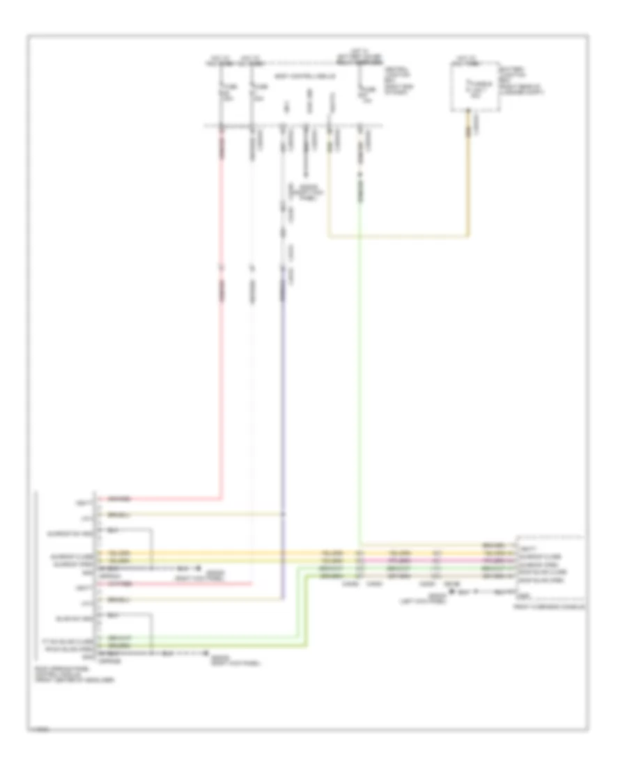
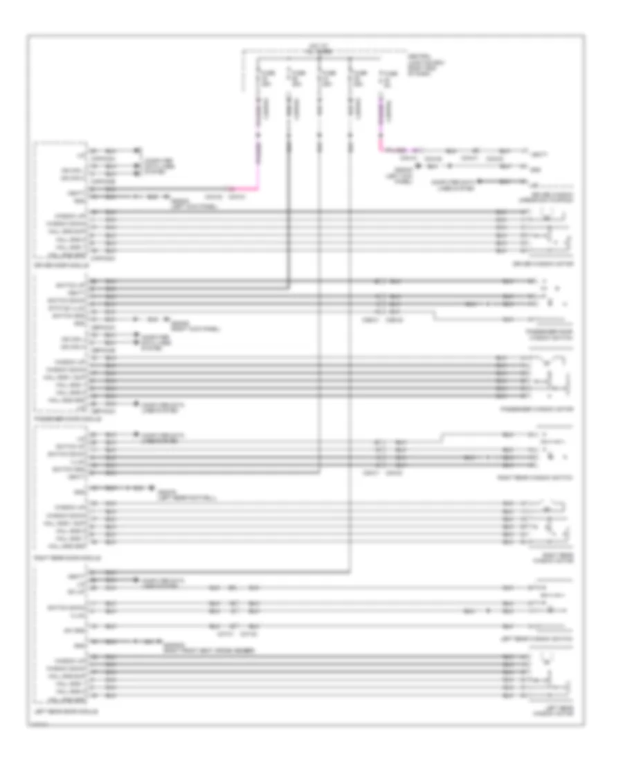
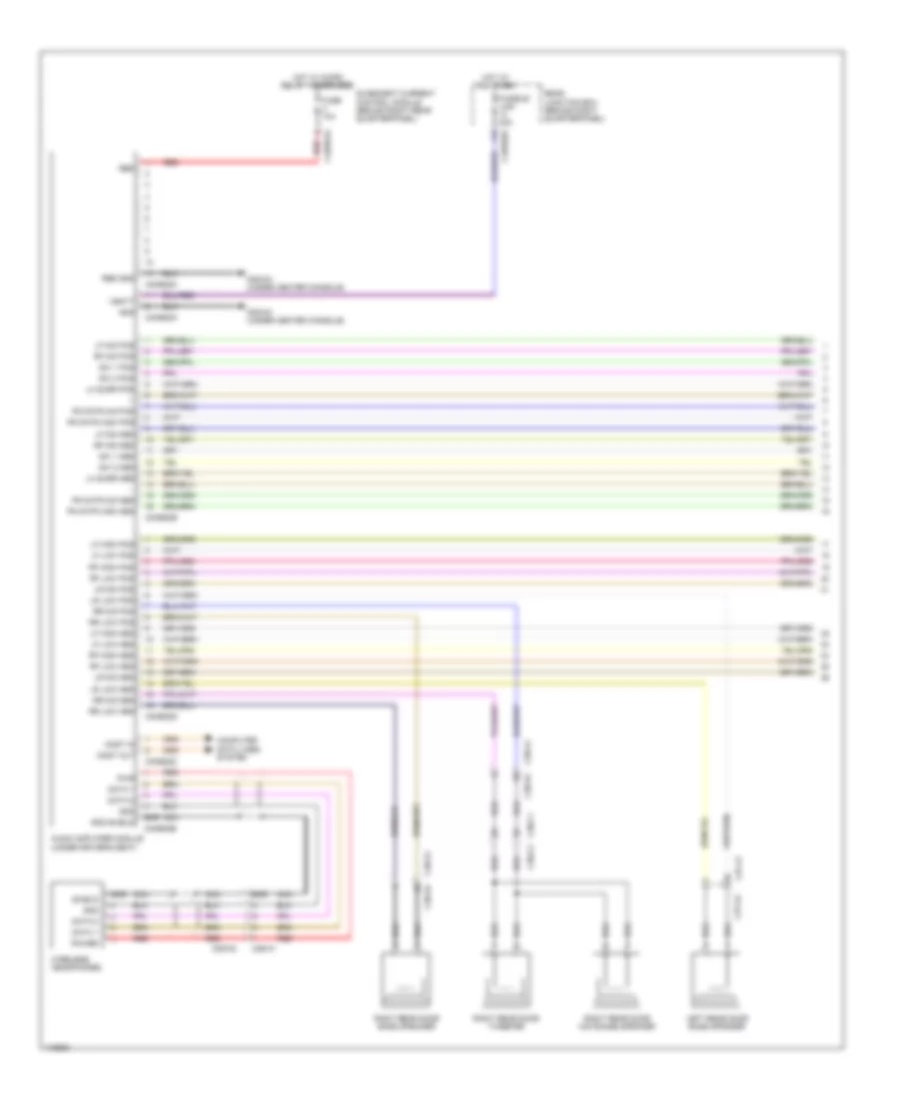
AIR CONDITIONING Automatic A/C Wiring Diagram (1 of 5) for Land Rover Range Rover Sport SE 2014 List of elements for Automatic A/C Wiring Diagram (1 of 5) for Land Rover Range Rover Sport SE 2014: 91 (behind left quarterpanel) rear blower (on rear blower) blower control module Aspirator drive Aspirator lsd Automatic temperature control module Blower ctrl (pwm) C12-a1 C12-a2 C1hf01a C1hf01am C2h101a C2h101b C31-k1 C31-k2 C32-f1 C32-f2 C32-g1 c32-g2 C32-g2 c32-g1 C32-ga1 C32-ga2 C32-n1 C32-n2 C45-a1 C45-a2 C45-b1 C45-b2 C4br01a C4br02a Changeover valve Clutch pwr in Compressor sol+ Compressor sol- Computer data lines system Ferrite core Fl face duct sens Fl foot duct sens Fr face duct sens Fr foot duct sens Ft blwr rly ctrl Fuel fired booster heater Fuse 10a Fuse 30a G1d123ar (right rear of engine compt) G1d123bs G2d215 (right center of dash) G2d233 (left kick panel) G4d349 (left rear of luggage compt) Gnd Hot at all times Hot w/ micro relay 2 energized Htd wshr Humidity sensor (top center of windshield) In car temp Left rear climate control temperature blend motor (rear of hvac unit) Lf solar sens Lin Lin 1 pwr (veh) Lin 2 Lin 3 Lin 4 Lin in Lin out Mag clutch Magnetic valve (under rear blower unit) Ms can h Ms can l Pos Press sens sig Ptc rly 1 ctrl Ptc rly 2 ctrl Pwm Pwr Quiescent current control module (qccm) (behind right rear quarterpanel) Rear blower relay Rear blwr rly ctrl Rear climate control temperature blend motor (upper middle of rear hvac unit) Rear junction box (behind right quarterpanel) Red Rf solar sens Right rear climate control temperature blend motor (rear of hvac unit) Rl face duct sensor Rl foot duct sens Rr blwr pwm Rr face duct sensor Rr foot duct sens Rr mag valve Seats system Sens gnd (veh) Sply 5v Vbatt Wiper/washer system Automatic A/C Wiring Diagram (2 of 5) for Land Rover Range Rover Sport SE 2014 List of elements for Automatic A/C Wiring Diagram (2 of 5) for Land Rover Range Rover Sport SE 2014: 29 Blower relay C12-a1 C12-a2 C1bb01b C31-a1 C31-a2 C31-b1 C31-b2 C32-ga1 C32-ga2 Engine junction box (right rear of engine compt) Fusible link 40a G1d124ar (right rear of engine compt) Gnd Hot at all times In-vehicle temperature sensor (lower left center of dash) Left front face duct air temperature sensor (upper left center of dash) Left front foot duct air temperature sensor (lower left center of dash) Left rear foot duct air temperature sensor (lower left center of dash) Mtr gnd Mtr pwr Ptc 1 relay Ptc 2 relay Red Right front face duct air temperature sensor (upper right center of dash) Right front foot duct air temperature sensor (lower right center of dash) Right rear foot duct air temperature sensor (lower right center of dash) Sig Wiper/washer system Automatic A/C Wiring Diagram (3 of 5) for Land Rover Range Rover Sport SE 2014 List of elements for Automatic A/C Wiring Diagram (3 of 5) for Land Rover Range Rover Sport SE 2014: 41 (behind right side of dash) front blower motor (lower right side of dash) electric booster heater (on a/c compressor) air conditioning (a/c) compressor solenoid (top center of dash) front sunload sensor (under center console) left rear face duct air temperature sensor (under center console) right rear face duct air temperature sensor C11-m1 C11-m2 C12-a1 C12-a2 C22-d1 C22-d2 C2hp01a C2hp01am C2hp01b C2hp01bm C31-l1 C31-l2 C32-a1 C32-a2 Cool air bypass motor (upper right side of hvac unit) Evap temp Evaporator temperature sensor G2d215 (right center of dash) G3d383b (right front seat cross member) Gnd Lh sig Lin in Lin out Pos Pwr Recirculation motor (right side of blower housing) Refrigerant pressure sensor Rh sig Right front face/feet motor (upper right side of hvac unit) Right front temperature blend motor (lower right side of hvac unit) Right rear temperature blend motor (lower right side of hvac unit) Sens gnd Sig Signal Sply 5v+ Automatic A/C Wiring Diagram (4 of 5) for Land Rover Range Rover Sport SE 2014 List of elements for Automatic A/C Wiring Diagram (4 of 5) for Land Rover Range Rover Sport SE 2014: 24 (left side of hvac unit) left rear temperature blend motor (lower left side of hvac unit) left front temperature blend motor (lower left side of hvac unit) rear face/ feet motor (upper left side of hvac blower housing) pollution sensor (upper left side of hvac unit) demist distribution motor (upper left side of hvac unit) left front face/feet motor Aqs pwm Automatic temperature control module C2h101c Evap temp G1d108f (bottom left rear of engine) Gnd Heater block (bottom left side of engine block) Lin 1 (hvac) Lin 1 gnd (hvac) Lin 2 (hvac) Lin 2 gnd (hvac) Lin 2 pwr (hvac) Lin in Lin out Lin pwr (hvac) Pwr Sens gnd (hvac) Sig output Automatic A/C Wiring Diagram (5 of 5) for Land Rover Range Rover Sport SE 2014 List of elements for Automatic A/C Wiring Diagram (5 of 5) for Land Rover Range Rover Sport SE 2014: 70 (lower left rear of radiator) supercharge coolant pump 3.0l 5.0l sc Air charge coolant pump relay Ambient air temperature sensor B d canh1 B d canl1 C11-u1 C11-u2 C1bb01b C1e120a C1e120b C1e121a C1e346 C1e346m C1ec01c C1ec01cm C2bp01c C31-j1 C31-j2 C31-l1 C31-l2 C3a-a1 C3a-a2 C3b-a1 C3b-a2 Central junction box (right end of dash) Computer data lines system Driver side door mirror Engine control module (ecm) (left rear of engine compt) Engine control module cooling fan motor Engine controls system Engine coolant temperature sensor (center rear of engine) Engine junction box (right rear of engine compt) Front electric cooling fan (front of radiator) Fuse 10a Fuse 15a Fusible link 11 40a Fusible link 5 40a G g bat1 G r engts G r sens G1d121al (left rear of engine compt) G1d123bs G1d131ar (right front wheelwell) G1d133as (right front of engine compt) Gnd Gr ats Hot at all times Hot w/ battery saver relay energized Hot w/ engine control module relay energized I a engts I a radwts I t fss Ia ats Ign O s cacwpr O s pcf O t eclg2 O t evf Passenger side door mirror Pwm Radiator outlet temperature sensor (left rear of radiator) Red Sig V v bat 1r V v bat 2r V v bat 3r Vbatt Viscous cooling fan (behind radiator) Cool Box Wiring Diagram for Land Rover Range Rover Sport SE 2014 List of elements for Cool Box Wiring Diagram for Land Rover Range Rover Sport SE 2014: 9 C2bp01d C32-m1 C32-m2 Central junction box (right end of dash) Cooling fan Front cool box Fuse 10a G3d362 (under right rear seat) Hot w/ ignition relay energized Rear A/C Wiring Diagram for Land Rover Range Rover Sport SE 2014 List of elements for Rear A/C Wiring Diagram for Land Rover Range Rover Sport SE 2014: 30 (in duct near top of right "d" pillar) C2bp01c C33-y1 C33-y2 C45-a1 C45-a2 Central junction box (right end of dash) Computer data lines system Evap temp sens Evaporator temperature sensor Fuse 5a G3d362 (under right rear seat) Gnd Hot at all times Left rear foot duct air temperature sensor (lower left center of dash) Left rear headliner duct air temperature sensor (in duct near top of left "d" pillar) Lr face duct sens Lr foot duct sens Ms can h Ms can l Rear a/c sig Rear climate control panel Rear evap temp sens Right rear foot duct air temperature sensor (lower right center of dash) Right rear headliner duct air temperature sensor Rr face duct sens Rr foot duct sens Sens gnd Sig Vbatt
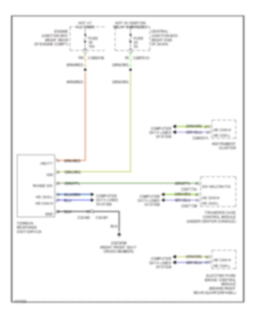
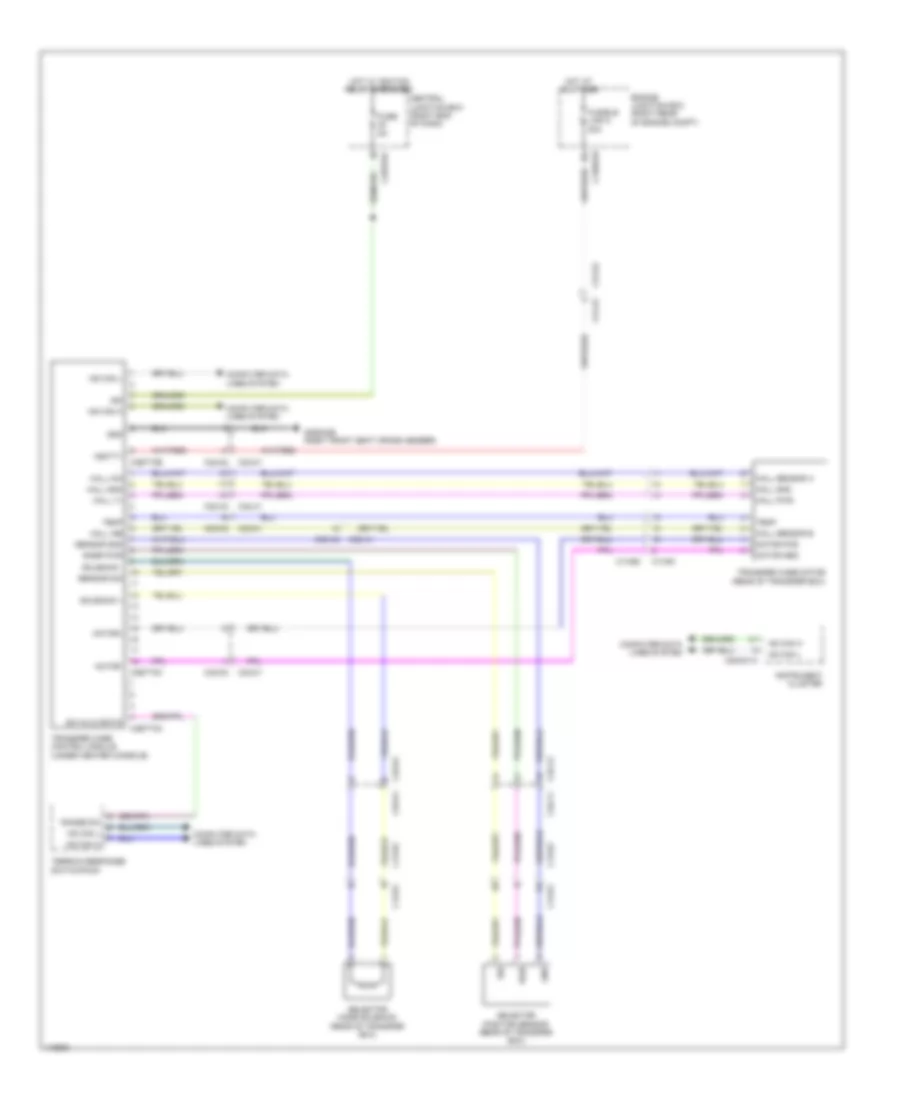
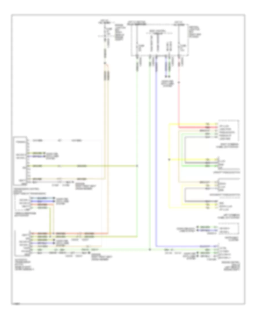
ANTI-LOCK BRAKES Anti Lock Brake Wiring Diagram for Land Rover Range Rover Sport SE 2014 List of elements for Anti Lock Brake Wiring Diagram for Land Rover Range Rover Sport SE 2014: 68 (left front wheelwell) g1d129ar Abs module (left front of engine compt) Brake diag sw Brake diagnostic switch Brake fluid level sensor (in brake fluid reservoir) Brake pedal switch (top of brake pedal assembly) Brake sw sig Brk fluid lvl sw C1bb01b C2bp01a C2bp01b C2bp01e C2bp01f C2bp01g C2mc01a C31-j1 C31-j2 C31-k1 C31-k2 C32-a1 C32-a2 C44-a1 C44-a2 C4br02a Central junction box (right end of dash) Computer data lines system Engine junction box (right rear of engine compt) Exterior lights system Fl pwr Fl rtn Fr pwr Fr rtn Fuse 5a Fusible link 12 30a Fusible link 7 40a G1d120bs (left rear of engine compt) G1d129al (left front wheelwell) G2d233 (left kick panel) Gnd Hot at all times Hot w/ ignition relay energized Hs can h Hs can h (ch) Hs can h (pt) Hs can l Hs can l (ch) Hs can l (pt) Ign Instrument cluster Left front wheel speed sensor (on left front wheel hub assembly) Left rear wheel speed sensor (on left rear wheel hub assembly) Ms can h Ms can l Nca Outh Outl Pump gnd Rear junction box (behind right quarterpanel) Red Right front wheel speed sensor (on right front wheel hub assembly) Right rear wheel speed sensor (on right rear wheel hub assembly) Rl pwr Rl rtn Rr pwr Rr rtn Stoplamp switch Valve gnd Vbatt Terrain Response Wiring Diagram for Land Rover Range Rover Sport SE 2014 List of elements for Terrain Response Wiring Diagram for Land Rover Range Rover Sport SE 2014: 26 C1bb01b C2bp01c C2mc01a C32-m1 C32-m2 C3et73a C3et73b Central junction box (right end of dash) Computer data lines system Electric park brake control module (behind right rear quarterpanel) Engine junction box (right rear of engine compt) Fuse 15a Fuse 5a G3d383b (right front seat cross member) Gnd Hot at all times Hot w/ ignition relay energized Hs can h Hs can l Ign Instrument cluster Range sw Sw hi/lo ratio Terrain response switchpack Transfer case control module (under center console) Vbatt
ANTI-THEFT Anti-theft Wiring Diagram, Active for Land Rover Range Rover Sport SE 2014 List of elements for Anti-theft Wiring Diagram, Active for Land Rover Range Rover Sport SE 2014: 96 Ajar sw Alarm led Anti-theft alarm warning ind Batt Battery backup sounder (right rear of engine compt) Battery junction box (bjb) (right rear of luggage compt) Body control module (bcm) C11-ac1 C11-ac2 C29-b1 C29-b2 C2bp01a C2bp01b C2bp01c C2bp01d C2bp01e C2bp01f C2bp01g C31-j1 C31-j2 C31-l1 C31-l2 C32-d2 c32-d1 C37-a1 C37-a2 C38-a1 C38-a2 C3a-a1 C3a-a2 C3b-a1 C3b-a2 C49-a1 c49-a2 C49-a2 c49-a1 C4bf01d C4bf01f C4bf01g C4pk28a Can h ms Can l ms Capw02a Cbpw04a Central junction box (cjb) (right end of dash) Child lck feedback Child lck gnd Computer data lines system Data Driver central door locking motor Driver door module Electronic gnd Exterior lights system Ferrite core Fl ajar sw Fr ajar sw Front overhead console Fuse 1 5a Fuse 36 5a Fusible link 4 60a Fusible link 6 40a Fusible link 7 40a G1d123al (right rear of engine compt) G1d129bl (left front wheelwell) G2d233 (left kick panel) G2d238 (right kick panel) G3d375 (left rear footwell) G3d383c (right front seat cross member) G4d350 (left rear of luggage compt) Gnd Headlights system Hood ajar sw Hood switch (left front of engine compt) Horn rly Horns Hot at all times Instrument cluster Keyless vehicle module (behind left rear quarterpanel) Latch gnd Left rear central door locking motor Left rear door module Lh di lamp Lh rear fog Lin 2 Ms can h Ms can l Passenger door central locking motor Passenger door module Radio frequency (rf) receiver Rain/light sensor (top center of windshield) Red Rh di lamp Rh rear fog Right rear central door locking motor Right rear door module Rl ajar sw Rr ajar sw Rx serial data System Anti-theft Wiring Diagram, Passive for Land Rover Range Rover Sport SE 2014 List of elements for Anti-theft Wiring Diagram, Passive for Land Rover Range Rover Sport SE 2014: 79 5 seat 7 seat Batt Battery junction box (bjb) (right rear of luggage compt) Body control module (bcm) C11-ac1 C11-ac2 C2bp01a C2bp01b C2bp01c C2bp01d C2bp01f C31-a1 C31-a2 C32-m1 C32-m2 C32-x1 C32-x2 C33-y1 C33-y2 C43-a1 C43-a2 C44-h1 C44-h2 C44-t1 C44-t2 C49-a1 c49-a2 C4bf01d C4bf01f C4bf01g C4pk28a C4pk28b Center luggage compartment lf antenna (center front of luggage compt) Central junction box (cjb) (right end of dash) Computer data lines system Data Front ant pos Front cabin ant pos Front cabin lf antenna (under front of center console) Front center console lf antenna (under front of center console) Fuse 5a Fusible link 4 60a Fusible link 6 40a Fusible link 7 40a G1d123al (right rear of engine compt) G2d238 (right kick panel) G2d284 (left center of dash) G3d347 (behind left rear quarterpanel) G4d350 (left rear of of luggage compt) Gnd Hot at all times Immobilizer antenna unit (under steering column) Instrument cluster Int trunk ant pos Keyless vehicle module (behind left rear quarterpanel) Left luggage compartment lf antenna (behind left rear quarterpanel) Lin Lin 4 Loadspace ant pos Logic gnd Ms can h Ms can l Passive sounder Passive sounder (right rear of engine compt) Radio frequency (rf) receiver Rear cabin ant pos Rear center console lf antenna (under rear of center console) Rear external lf antenna (center of tailgate) Red Right luggage compartment lf antenna (behind right quarterpanel) Rx serial data Start stop sw 2 Start stop switch Start- stop gnd Sw 1 start stop Switch 1 Switch 2 Third row lf antenna Vbatt
BODY CONTROL MODULES Body Control Modules Wiring Diagram (2 of 2) for Land Rover Range Rover Sport SE 2014 List of elements for Body Control Modules Wiring Diagram (2 of 2) for Land Rover Range Rover Sport SE 2014: 97 Act pwr Anti-theft system Aux sw rtn Body control module (bcm) Brk fluid level sensor C2bp01c C2bp01d C2bp01e C2bp01f C2bp01h Central junction box (right end of dash) Col adj easy entry Col motor extend Column motor down Column motor retract Column tilt/up Computer data lines system Coolant level sw Defogger system Dip beam lh Dip beam rh Door locks & anti-theft systems Door locks & trunk, tailgate, fuel doors systems Door locks system Elec gnd Engine controls system Escl pwr Exterior lights & mirrors systems Exterior lights system F wip park sw F/pump rly lsd G2d238 (right kick panel) Glovebox lower latch drive Hazard sw illum Headlamp power lh Headlamp power rh Headlights system Hfs rly Hood ajar sw Horn rly ctl Horns system Hs can h Hs can l I col adj hall count telescope I col adj hall count tilt Instrument cluster system Int lights dimming Interior lights system Lh di front Lh di rear Lh rear fog Lh stop lamp Lin 5 Low pr lh h lamp Lower glove box release Memory systems Memory systems exterior lights & instrument cluster systems interior lights system Motor + Motor - Oil press sw Passive sounder Pos lmp rr lh Pos lmp rr rh Power wash rly Pwr gnd Rear fog rh Reverse lamp lh Rh di front Rh di rear Rh rear fog Rh reverse lamp Rh stop lamp Sbr buckle lh sw Sbr buckle mid sw Sbr buckle rh sw Shift interlock system Start request Starting/charging system Tpms antenna fl + Tpms antenna fl - Tpms antenna fr + Tpms antenna fr - Trailer lh di lamp Trailer rh di lamp Transit relay Trunk, tailgate, fuel doors system Upper tailgate release Vbatt1 Vbatt2 Vbatt3 Vbatt4 Wake up Warning systems Wash fluid level sw Wip fast/slow ctrl Wiper rly on/off Wiper/washer system
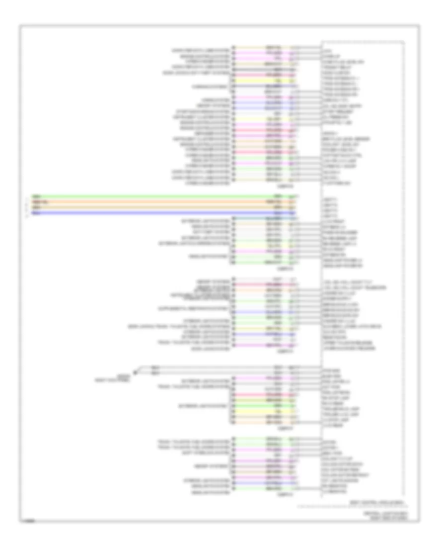
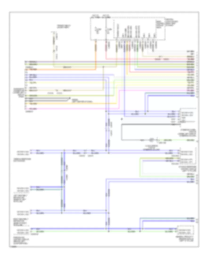
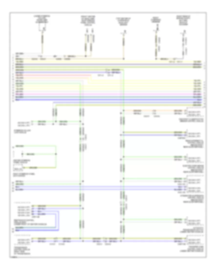
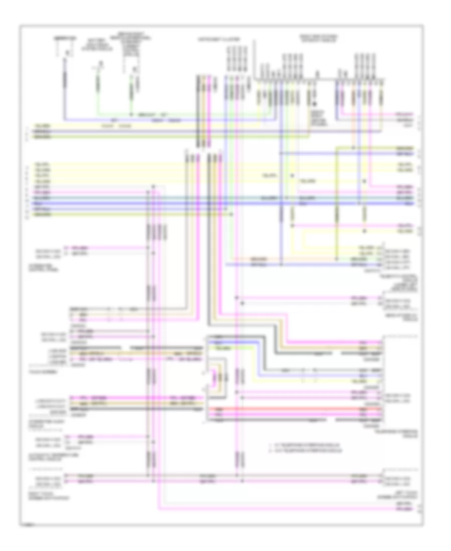
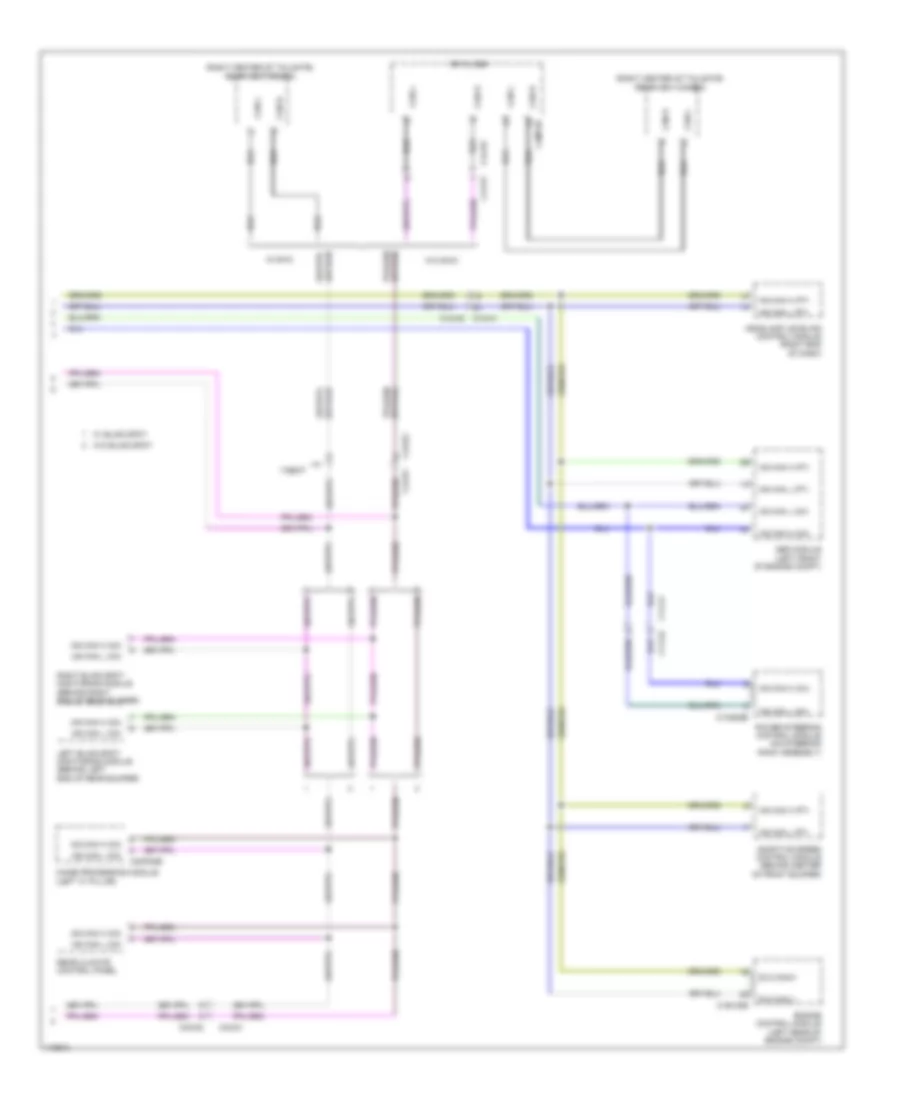
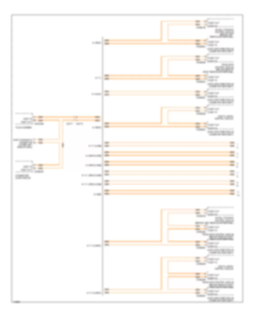
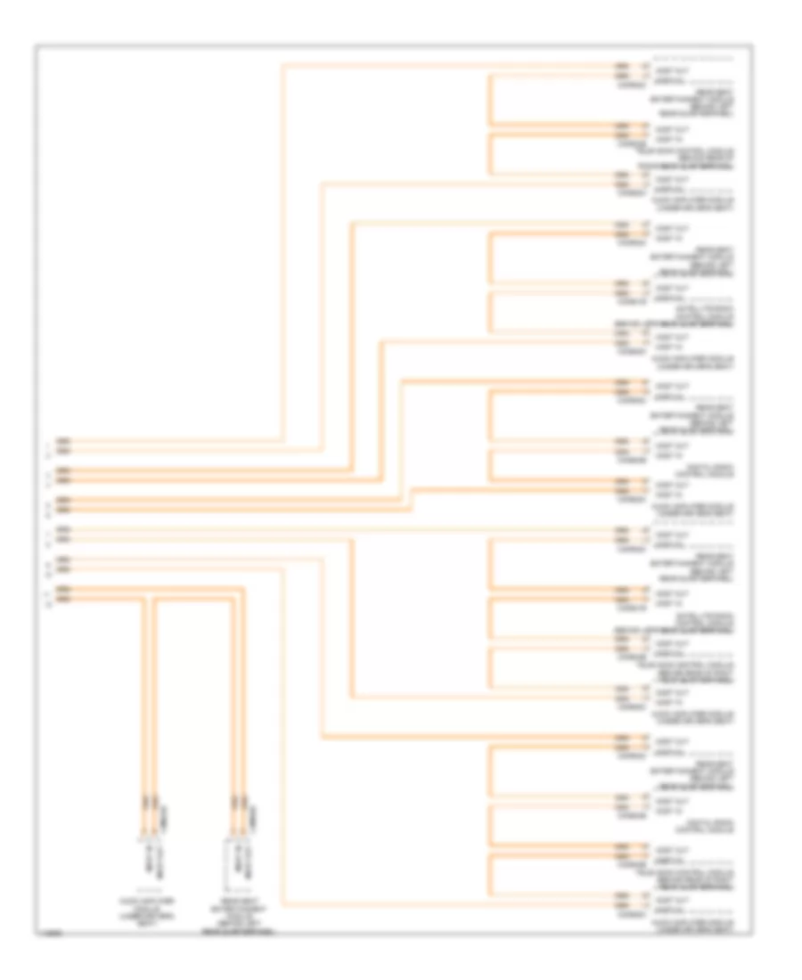
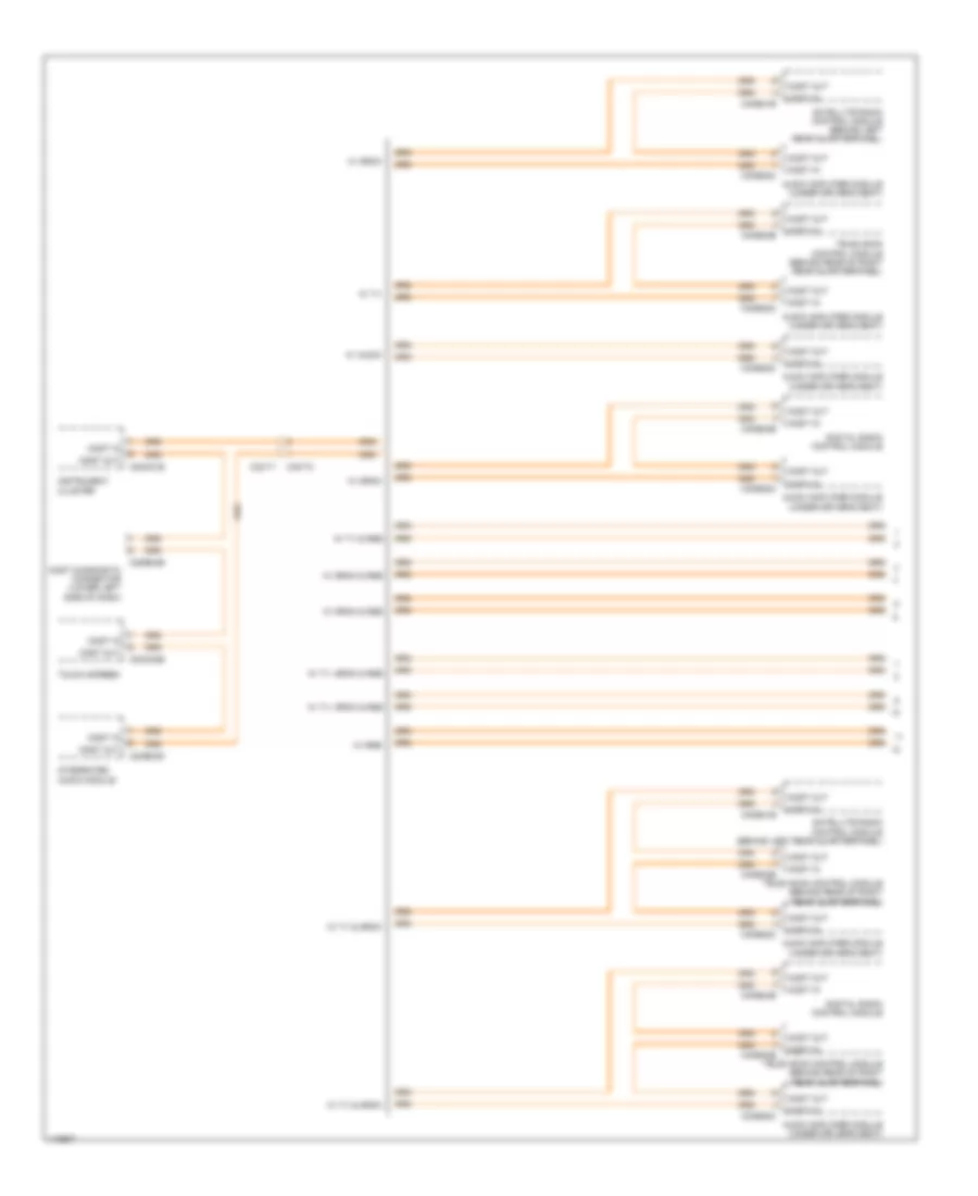
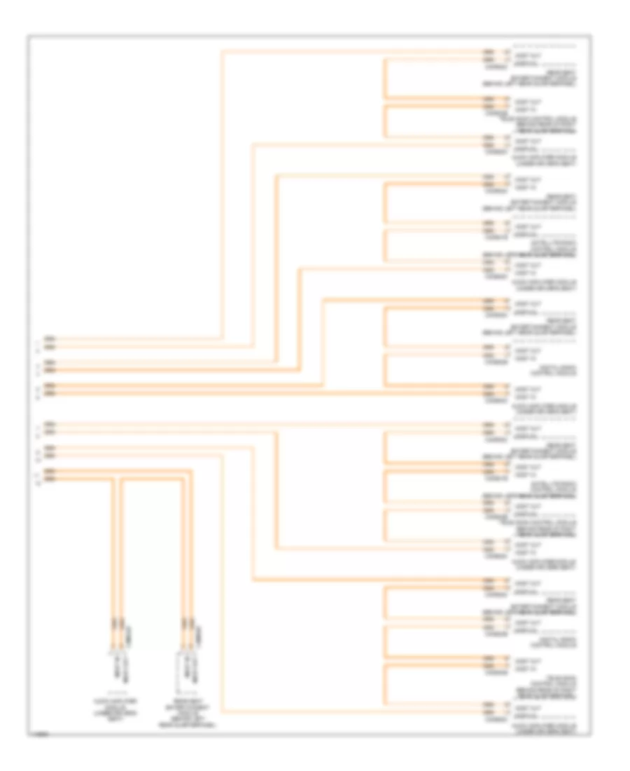
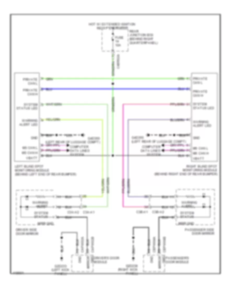
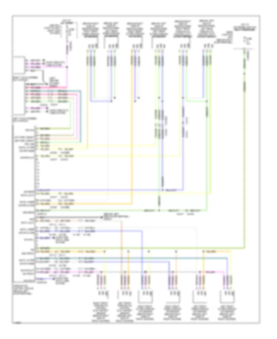
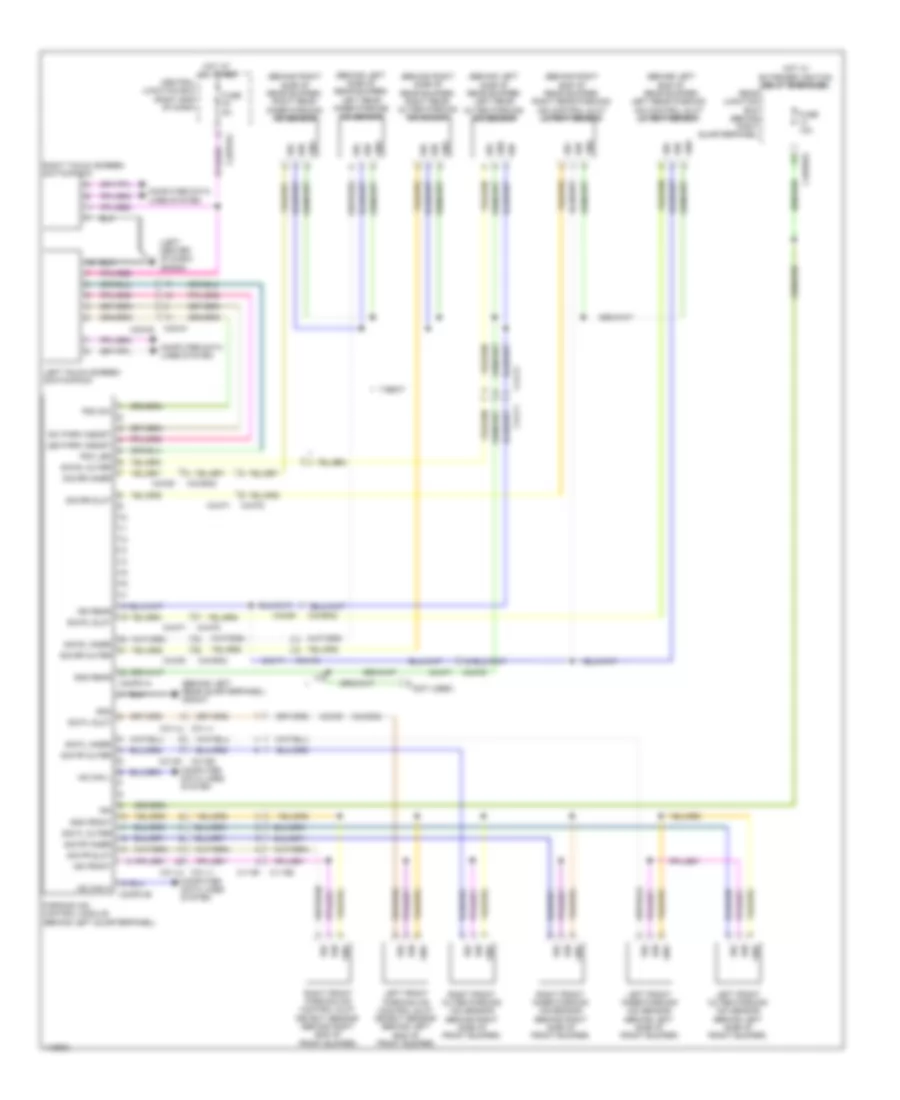
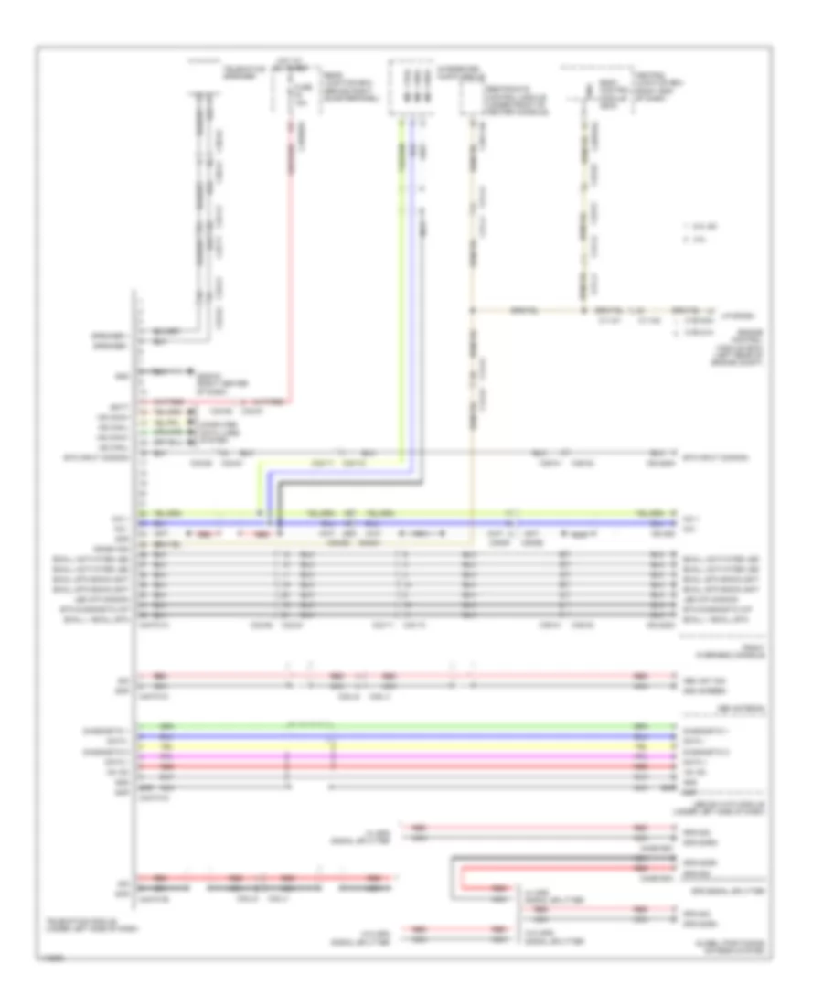
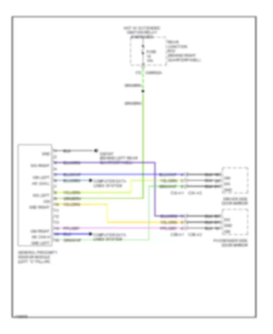
COMPUTER DATA LINES Diagnostic Socket Wiring Diagram (1 of 5) for Land Rover Range Rover Sport SE 2014 List of elements for Diagnostic Socket Wiring Diagram (1 of 5) for Land Rover Range Rover Sport SE 2014: 51 Body control module (bcm) C12-a1 C12-a2 C2bp01a C2bp01b C2bp01c C2bp01e C2db04a C2db04c C2r115b C31-j1 C31-j2 C32-d1 C32-d2 C32-g1 C32-g2 C32-m1 C32-m2 C3cl54c C3cl54d C3mp01b C4dc27 Central junction box (right end of dash) Clock spring (top of steering column) Diagnostic connector (lower left end of dash) Dynamic response control module (left "a" pillar) Fuse 5a G2d284 (left center of dash) General proximity sensor module (left "c" pillar) Hot at all times Hs can h (ch) Hs can h (pt) Hs can l (ch) Hs can l (pt) Left seatbelt retractor (base of left "b" pillar) Lin 1 Lin 1 lin 3 Lin 2 Lin 3 Lin 4 Ms can h (bo) Ms can l (bo) Nca Parking aid control module (behind left quarterpanel) Right seatbelt retractor (base of right "b" pillar) Steering wheel module (upper left side of steering column) Terrain response switchpack Transit relay Transit relay (on battery) Trip Trip comp Diagnostic Socket Wiring Diagram (2 of 5) for Land Rover Range Rover Sport SE 2014 List of elements for Diagnostic Socket Wiring Diagram (2 of 5) for Land Rover Range Rover Sport SE 2014: 48 (front center of headliner) roof opening panel control module (right rear of engine compt) battery back-up sounder (top center of windshield) rain/light sensor (under steering column) immobilizer antenna unit Automatic transmission switch (under center console) Bcm lin C11-ac1 C11-ac2 C13-c1 C13-c2 C29-b1 C29-b2 C31-l1 C31-l2 C32-f1 C32-f2 C32-n1 C32-n2 C32-x1 C32-x2 C33-k1 C33-k2 C3et73b C3r114b C49-e1 C49-e2 C4cl14c C4cl14d C4et63c Electric park brake control module (behind right rear quarterpanel) Front overhead console Heated steering wheel module Hs can h (ch) Hs can h (pt) Hs can l (ch) Hs can l (pt) Ims lin Integrated suspension control module (behind right rear quarterpanel) Lin Lin 3 c9pr32a Lin 3 c9pr32b Occupant classification sensor control module Rear differential control module (behind right rear quarterpanel) Restraints control module (rcm) (under front of center console) Right steering wheel switchpack Steering column lock module Transfer case control module (under center console) Transmission control module (right side of transmission) Diagnostic Socket Wiring Diagram (3 of 5) for Land Rover Range Rover Sport SE 2014 List of elements for Diagnostic Socket Wiring Diagram (3 of 5) for Land Rover Range Rover Sport SE 2014: 59 (behind right rear quarterpanel) quiescent current control module (or red) (right end of dash) gateway module Automatic temperature control module Battery monitoring system module C12-a1 C12-a2 C2h101a C2mc01a C2mc01c C2mc02a C2mc02i C2mc02j C2me03f C2mm25a C2mm25d C2mm25e C2mm25f C32-n1 C32-n2 C4br01a C4mt01a G2d215 (right center of dash) Generator Gnd Head-up display module Hs can h (ch) Hs can h (pt) Hs can l (ch) Hs can l (pt) Instrument cluster Integrated audio module Integrated control panel Left touch screen switchpack Lin Lin 3 Lin1 Lin2 Lvds data out+ Lvds data out- Lvds scr Lvds-pos Ms can h (bo) Ms can h (co) Ms can l (bo) Ms can l (co) Nca Red Right touch screen switchpack Scr Scr gnd Telematic control module (under left side of dash) Telephone interface module Touch screen Vbatt1 Vbatt2 Vfet W/ telephone interface module W/o telephone interface module Diagnostic Socket Wiring Diagram (4 of 5) for Land Rover Range Rover Sport SE 2014 List of elements for Diagnostic Socket Wiring Diagram (4 of 5) for Land Rover Range Rover Sport SE 2014: 72 12 way 8 way C12-a1 C12-a2 C32-f1 C32-f2 C32-g1 C32-g2 C32-n1 C32-n2 C33-j1 C33-j2 C33-k1 C33-k2 C37-a1 C37-a2 C37-c1 C37-c2 C38-a1 C38-a2 C38-c1 C38-c2 C3a-a1 C3a-a2 C3a-c1 C3a-c2 C3b-a1 C3b-a2 C3b-c1 C3b-c2 C3ps02b C3ps02f C3ps185b C3ps186b C3ps71b C3ps71f C44-ae1 C44-ae2 C44-r1 C44-r2 C44-u1 C44-u2 C4pk28a C4pr47b C4pr59b C4y124d Capw02a Capw02b Cbpw04b Deployable sidestep control module (right "c" pillar) Driver door module Driver door pocket ambience lighting Driver seat module (w/ memory) Driver window mirror switchpack Keyless vehicle module (behind left rear quarterpanel) Left rear door module Left rear door pocket ambience lighting Left rear seat module Lin Lin2 Ms can h (bo) Ms can l (bo) Passenger door module Passenger door pocket ambience lighting Passenger seat module (w/ memory) Powered tailgate module (right side of tailgate) Rear view mirror Right rear door module Right rear door pocket ambience lighting Right rear seat module Vbatt2 Vfet Diagnostic Socket Wiring Diagram (5 of 5) for Land Rover Range Rover Sport SE 2014 List of elements for Diagnostic Socket Wiring Diagram (5 of 5) for Land Rover Range Rover Sport SE 2014: 40 (right center of tailgate) rearview camera 7-seat Abs module (left front of engine compt) Adaptive speed control module (behind center of front bumper) B d canh1 B d canl1 C11-g1 C11-g2 C12-a1 C12-a2 C1cs05b C1e120b C32-d1 C32-d2 C3mp22b C43-b1 C43-b2 C44-r1 C44-r2 C4mp40 Can h Can l Engine control module (left rear of engine compt) Headlamp leveling control module (right end of dash) Hs can h (ch) Hs can h (pt) Hs can l (ch) Hs can l (pt) Image processing module (left "c" pillar) Left blind spot monitoring module (behind left end of rear bumper) Ms can h (co) Ms can l (co) Power steering control module (on steering rack assembly) Rear climate control panel Rf filter Right blind spot monitoring module (behind right end of rear bumper) W/ blind spot W/ swc W/o blind spot W/o swc Fibre Optic Network Wiring Diagram, Conventional Display (1 of 2) for Land Rover Range Rover Sport SE 2014 List of elements for Fibre Optic Network Wiring Diagram, Conventional Display (1 of 2) for Land Rover Range Rover Sport SE 2014: 30 (lower left side of dash) Audio amplifier module (under driver's seat) C2mc02b C2me03d C32-t1 C32-t2 C3me22c C4me24b C4me33b C4me41b Digital radio control module Integrated audio module Most diagnostic connector Most in Most out Satellite radio control module (behind left rear quarterpanel) Television control module (behind rear of right rear quarterpanel) Touch screen W/ audio W/ drcm W/ drcm & rse W/ rse W/ srcm W/ srcm & rse W/ tv W/ tv & drcm W/ tv & rse W/ tv & srcm W/ tv, drcm & rse W/ tv, srcm & rse Fibre Optic Network Wiring Diagram, Conventional Display (2 of 2) for Land Rover Range Rover Sport SE 2014 List of elements for Fibre Optic Network Wiring Diagram, Conventional Display (2 of 2) for Land Rover Range Rover Sport SE 2014: 12 Audio amplifier module (under driver's seat) C3me22c C4me24b C4me33b C4me41b C4mr02c Digital radio control module Most in Most out Rear seat entertainment module (behind left rear quarterpanel) Satellite radio control module (behind left rear quarterpanel) Television control module (behind rear of right rear quarterpanel) Fibre Optic Network Wiring Diagram, Virtual Display (1 of 2) for Land Rover Range Rover Sport SE 2014 List of elements for Fibre Optic Network Wiring Diagram, Virtual Display (1 of 2) for Land Rover Range Rover Sport SE 2014: 32 Audio amplifier module (under driver's seat) C2db04b C2mc01b C2mc02b C2me03d C32-t1 C32-t2 C3me22c C4me24b C4me33b C4me41b Digital radio control module Instrument cluster Integrated audio module Most diagnostic connector (lower left side of dash) Most in Most out Satellite radio control module (behind left rear quarterpanel) Television control module (behind rear of right rear quarterpanel) Touch screen W/ audio W/ drcm W/ drcm & rse W/ rse W/ srcm W/ srcm & rse W/ tv W/ tv & drcm W/ tv & rse W/ tv & srcm W/ tv, drcm & rse W/ tv, srcm & rse Fibre Optic Network Wiring Diagram, Virtual Display (2 of 2) for Land Rover Range Rover Sport SE 2014 List of elements for Fibre Optic Network Wiring Diagram, Virtual Display (2 of 2) for Land Rover Range Rover Sport SE 2014: 12 Audio amplifier module (under driver's seat) C3me22c C4me24b C4me33b C4me41b C4mr02c Digital radio control module Most in Most out Rear seat entertainment module (behind left rear quarterpanel) Satellite radio control module (behind left rear quarterpanel) Television control module (behind rear of right rear quarterpanel)
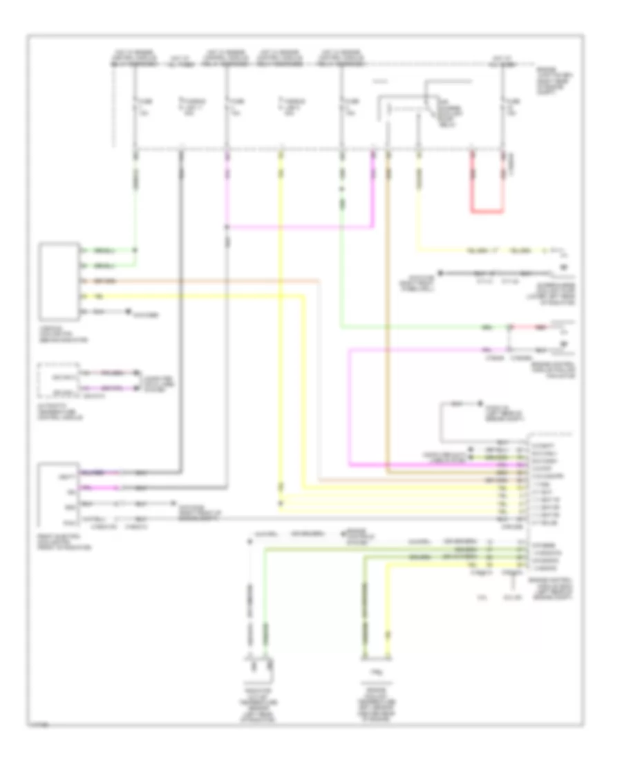
COOLING FAN Cooling Fan Wiring Diagram for Land Rover Range Rover Sport SE 2014 List of elements for Cooling Fan Wiring Diagram for Land Rover Range Rover Sport SE 2014: 58 3.0l 5.0l sc Air charge coolant pump relay Automatic temperature control module B d canh1 B d canl1 C11-u1 C11-u2 C1bb01b C1e120a C1e120b C1e121a C1e346 C1e346m C1ec01c C1ec01cm C2h101a Computer data lines system Engine control module (ecm) (left rear of engine compt) Engine control module cooling fan motor Engine controls system Engine coolant temperature (ect) sensor (center rear of engine) Engine junction box (right rear of engine compt) Front electric cooling fan (front of radiator) Fuse 10a Fuse 15a Fusible link 11 40a Fusible link 5 40a G g bat1 G r engts G r sens G1d121al (left rear of engine compt) G1d123bs G1d131ar (right front wheelwell) G1d133as (right front of engine compt) Gnd Hot at all times Hot w/ engine control module relay energized I a engts I a radwts I t fss Ign Ms can h Ms can l O s cacwpr O s pcf O t eclg2 O t evf Pwm Radiator outlet temperature sensor (left rear of radiator) Red Sig Supercharge coolant pump (lower left rear of radiator) V v bat 1r V v bat 2r V v bat 3r Vbatt Viscous cooling fan (behind radiator)
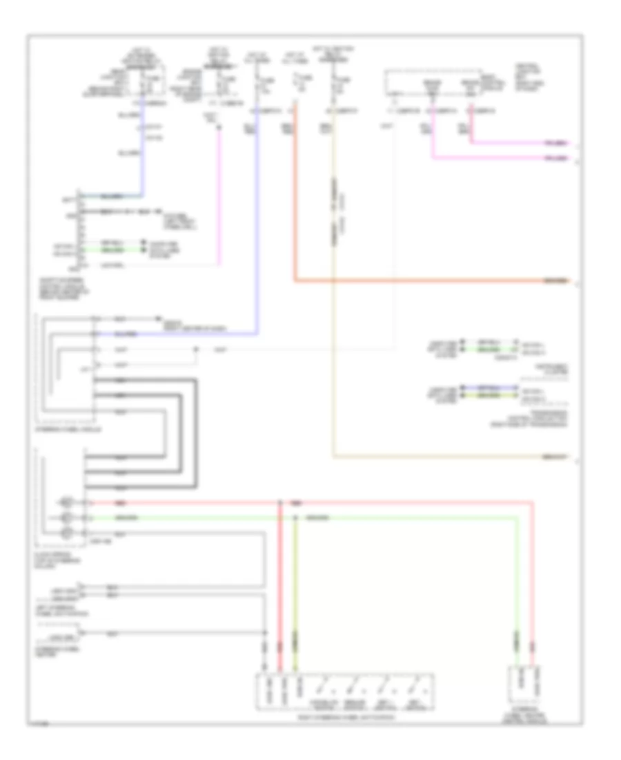
CRUISE CONTROL Cruise Control Wiring Diagram (1 of 2) for Land Rover Range Rover Sport SE 2014 List of elements for Cruise Control Wiring Diagram (1 of 2) for Land Rover Range Rover Sport SE 2014: 49 Adaptive speed control module (behind center of front bumper) Batt Bcm lin Body control module Brake diag sw Brake sw sig C1bb01b C2bp01a C2bp01g C2bpo1b C2bpo1c C2bpo1f C2mc01a C2r115b C31-k1 C31-k2 C4br02a Cancel/on switch Central junction box (right end of dash) Clock spring (top of steering column) Computer data lines system Engine junction box (right rear of engine compt) Fuse 10a Fuse 5a G1d129bl (left front wheelwell) G2d216 (right center of dash) Gnd Hot at all times Hot w/ extended ignition relay energized Hot w/ ignition relay energized Hs can h Hs can l Ign Instrument cluster Left steering wheel switchpack Lin 1 Logic gnd Logic pwr Nca Rear junction box (behind right quarterpanel) Red Resume switch Right steering wheel switchpack Set + switch Set - switch Steering wheel heater Steering wheel heater control module Steering wheel module Transmission control module (tcm) (right side of transmission) Cruise Control Wiring Diagram (2 of 2) for Land Rover Range Rover Sport SE 2014 List of elements for Cruise Control Wiring Diagram (2 of 2) for Land Rover Range Rover Sport SE 2014: 50 3.0l 5.0l sc Accelerator pedal position sensor (top of accelerator pedal assembly) Brake diagnostic switch Brake pedal switch (top of brake pedal assembly) Brk sw C1e120a C1e120b C1e121a C31-f1 C31-f2 C31-j1 C31-j2 C31-k1 C31-k2 C31-l1 C31-l2 C32-a1 C32-a2 Can-h1 Can-l1 Computer data lines system Demand 1 Demand 2 Electric throttle unit (on throttle body) Engine control module (ecm) (left rear of engine compt) G g batt 1 G r app1 G r app2 G r tva G1d121al (left rear of engine compt) G2d233 (left kick panel) Gnd 1 Gnd 2 I a app1 I a app2 I a tva1 I a tva2 I s brk sw I s brkos O t tva pos O v 5vapp1 O v 5vapp2 O v 5vtva Silver plated Stop lamp switch T15 Trailer brake control module (under left side of dash) Vref 1 Vref 2
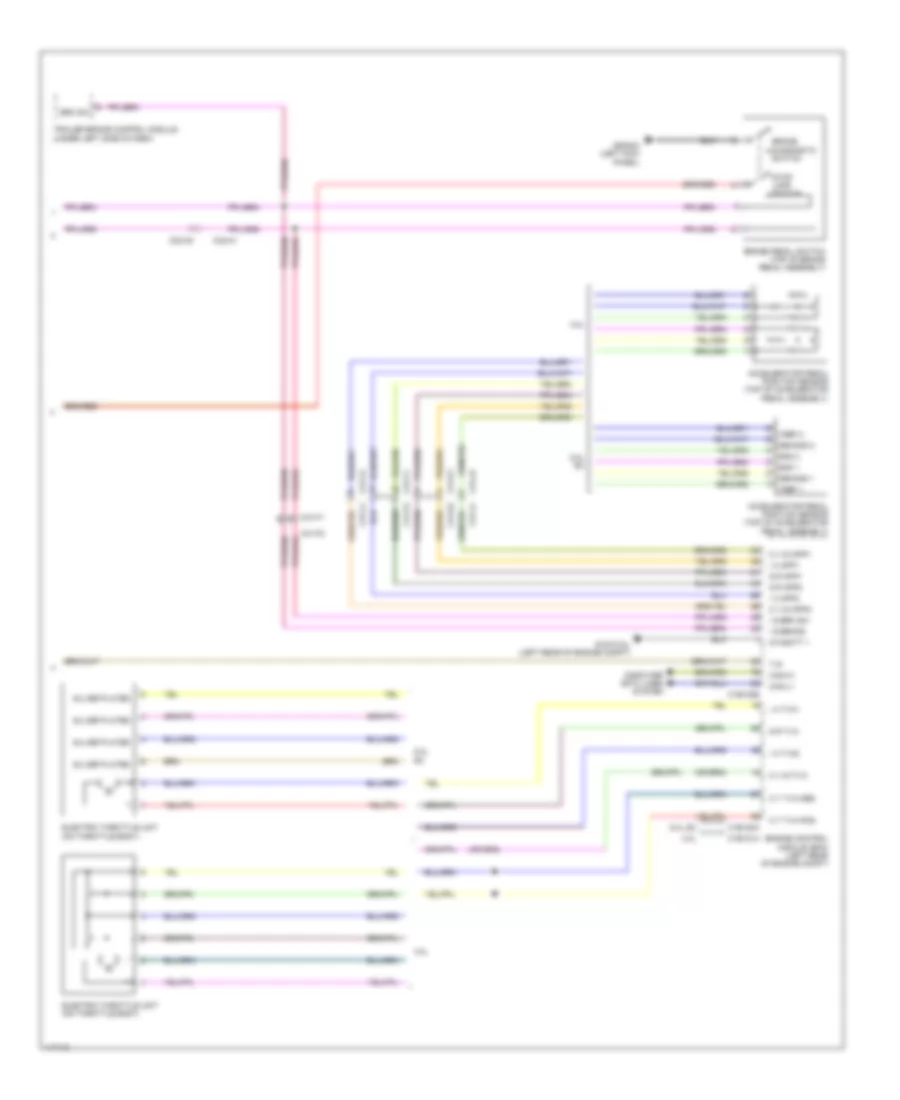
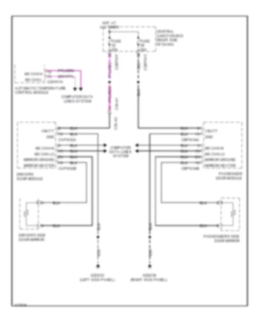
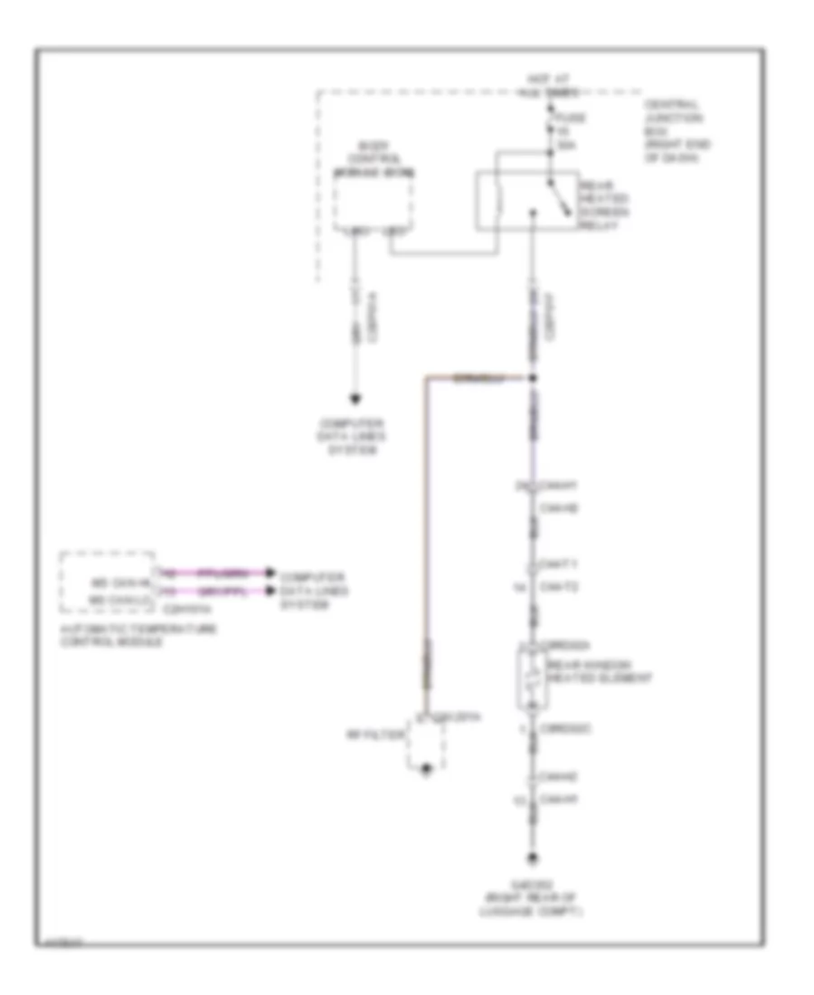
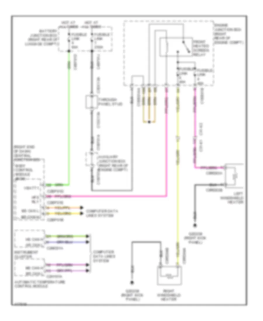
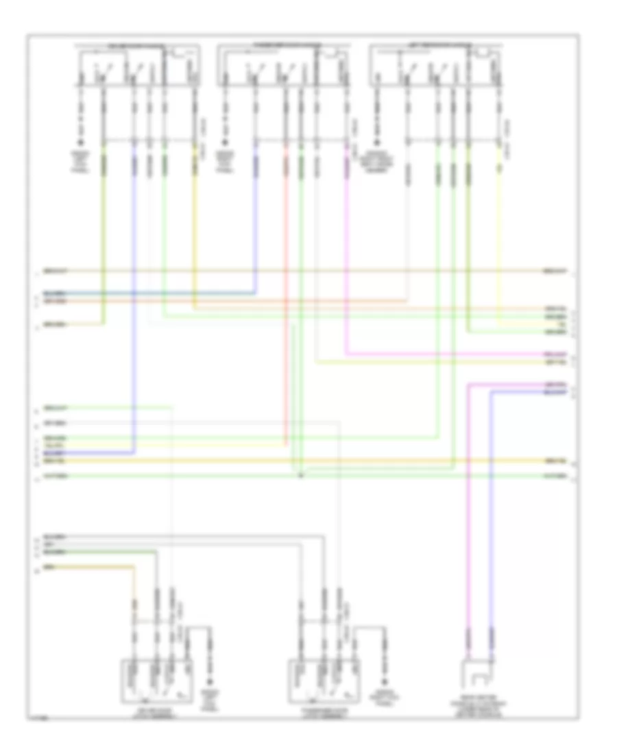
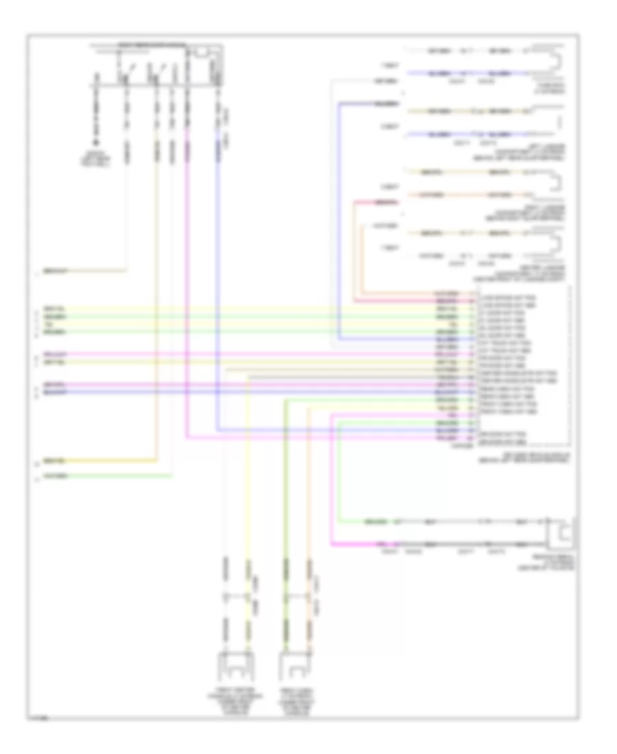
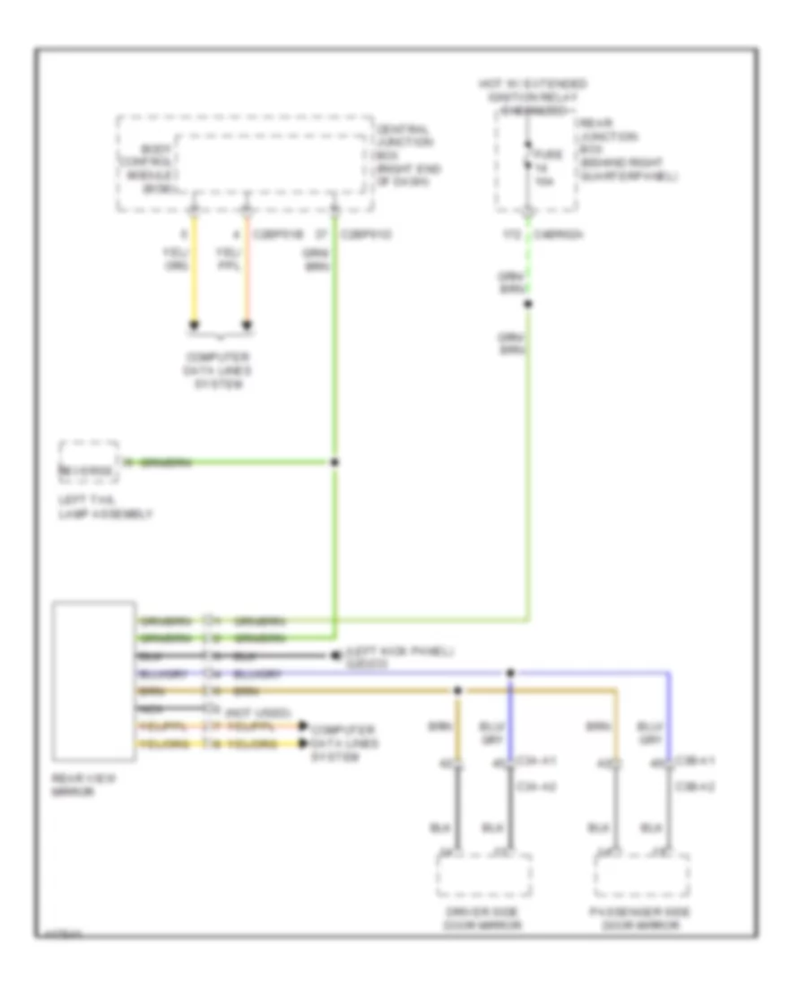
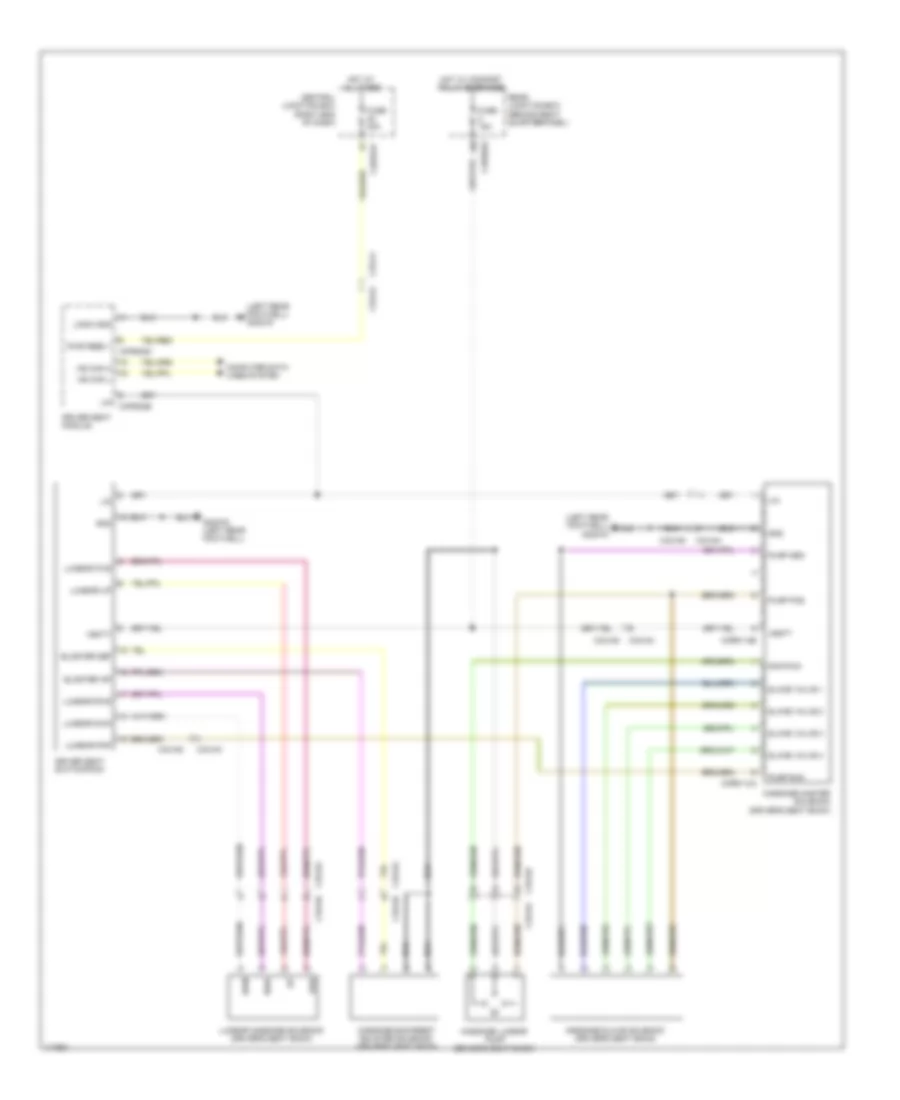
DEFOGGERS Heated Mirrors Wiring Diagram for Land Rover Range Rover Sport SE 2014 List of elements for Heated Mirrors Wiring Diagram for Land Rover Range Rover Sport SE 2014: 28 Automatic temperature control module C2bp01c C2bp01f C2h101a C3a-a1 C3a-a2 Capw02a Capw02b Cbpw04a Cbpw04b Central junction box (right end of dash) Computer data lines system Driver's door module Driver's side door mirror Fuse 25a G2d233 (left kick panel) G2d238 (right kick panel) Gnd Hot at all times Mirror ground Mirror heater Ms can h Ms can hi Ms can l Ms can lo Passenger door module Passenger's side door mirror Vbatt Heated Windshield Wiring Diagram for Land Rover Range Rover Sport SE 2014 List of elements for Heated Windshield Wiring Diagram for Land Rover Range Rover Sport SE 2014: 24 Automatic temperature control module Body control module (bcm) C2bp01a C2bp01f C2h101a C44-h1 C44-h2 C44-t1 C44-t2 C4x201a C9rd02a C9rd02c Central junction box (right end of dash) Computer data lines system Fuse 30a G4d352 (right rear of luggage compt) Hot at all times Lin3 Lsd Ms can hi Ms can lo Rear heated screen relay Rear window heated element Rf filter Rear Defogger Wiring Diagram for Land Rover Range Rover Sport SE 2014 List of elements for Rear Defogger Wiring Diagram for Land Rover Range Rover Sport SE 2014: 42 (right end of dash) central junction box Automatic temperature control module Auxiliary junction box (right rear of engine compt) c1bf01h Battery junction box (right rear of luggage compt) Body control module (bcm) C1bb01aa C1bb01b C1bf01a C1dc13a C2bp01b C2bp01d C2bp01e C2mc01a C31-k2 c31-k1 C3dc13a C4bf01d C4bf01j C9rd03a C9rd03b C9rd04a C9rd04b Computer data Computer data lines system Engine junction box (right rear of engine compt) Front heated screen relay Fusible link 250a Fusible link 40a Fusible link 60a G2d238 (right kick panel) Hfs rly Hot at all times Hs can h Hs can l Instrument cluster Left windshield heater Lines system Ms can h Ms can h ms can l c2h101a Ms can l Right windshield heater Through panel stud Vbatt1
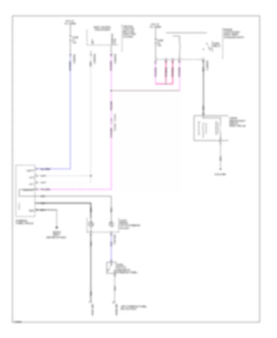
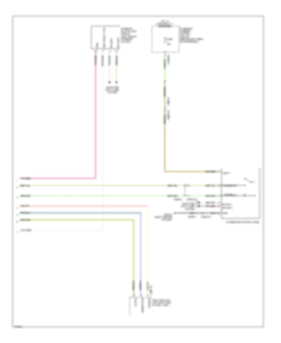
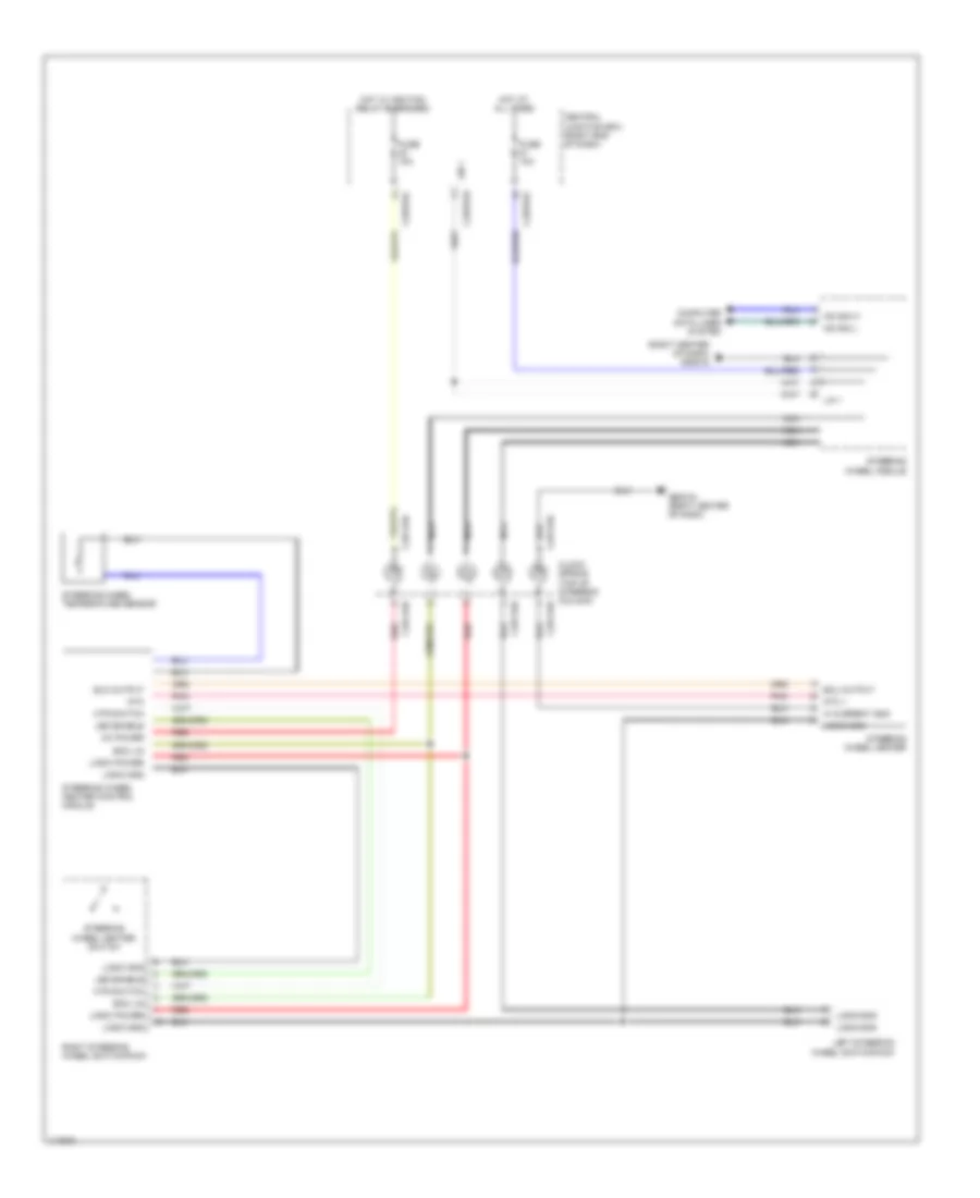
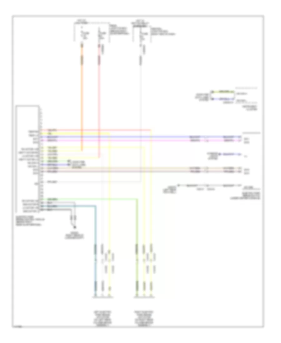
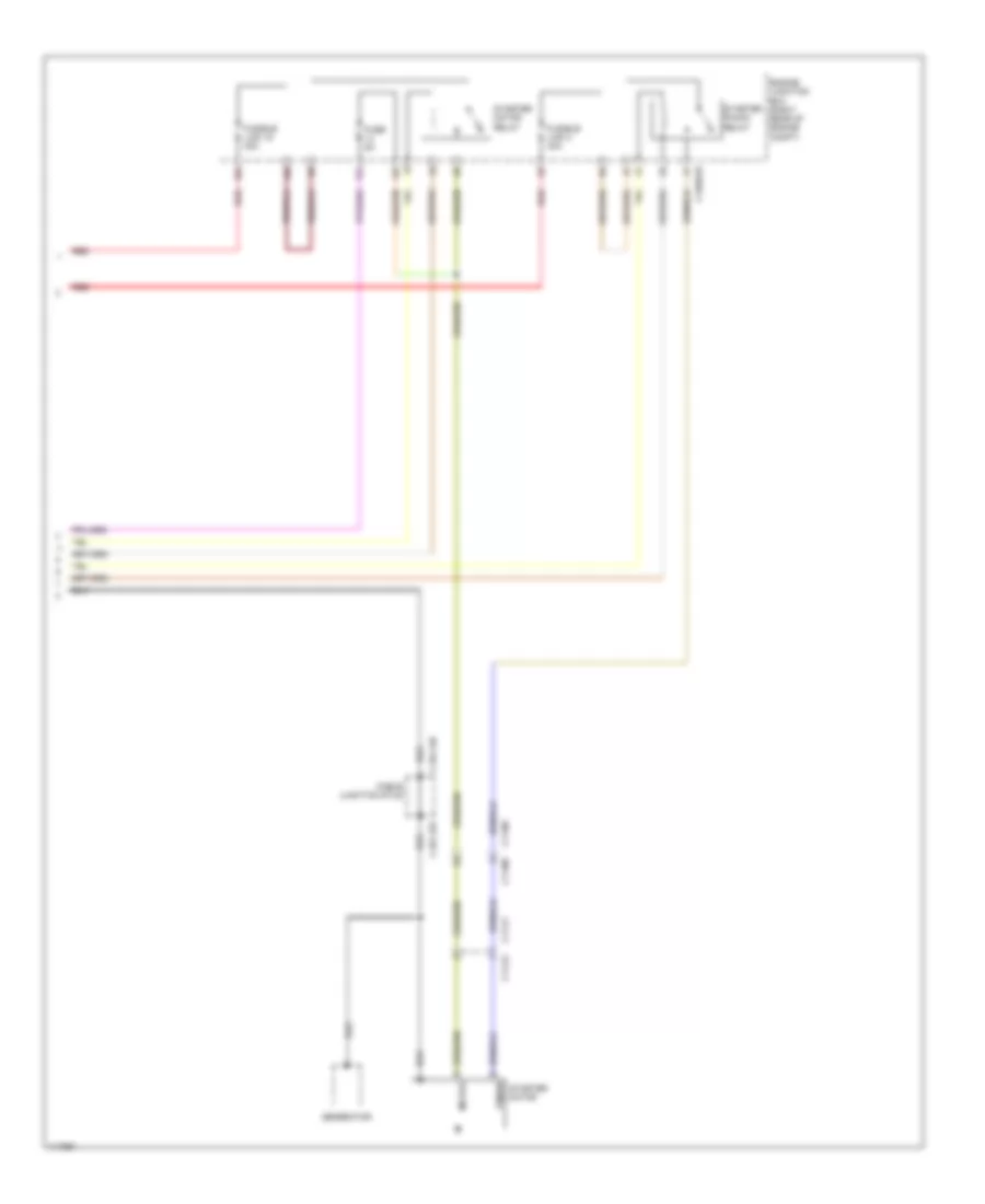
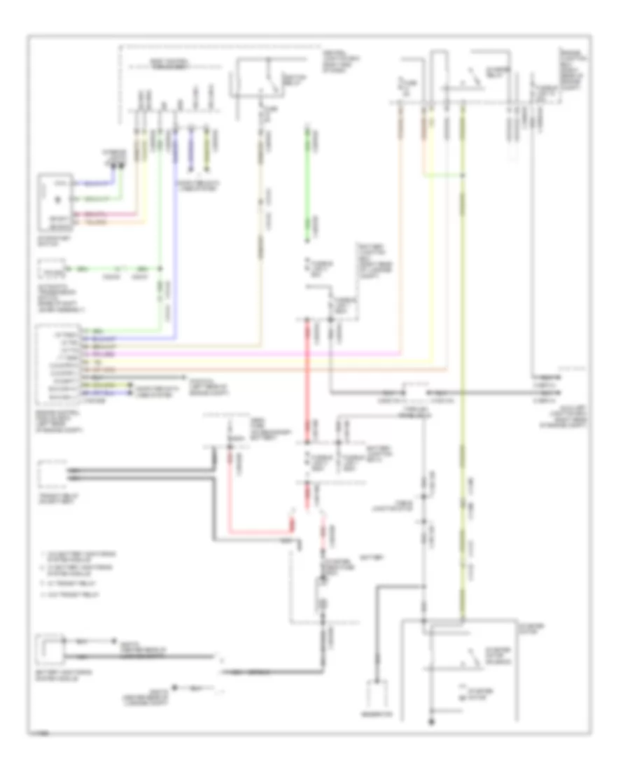
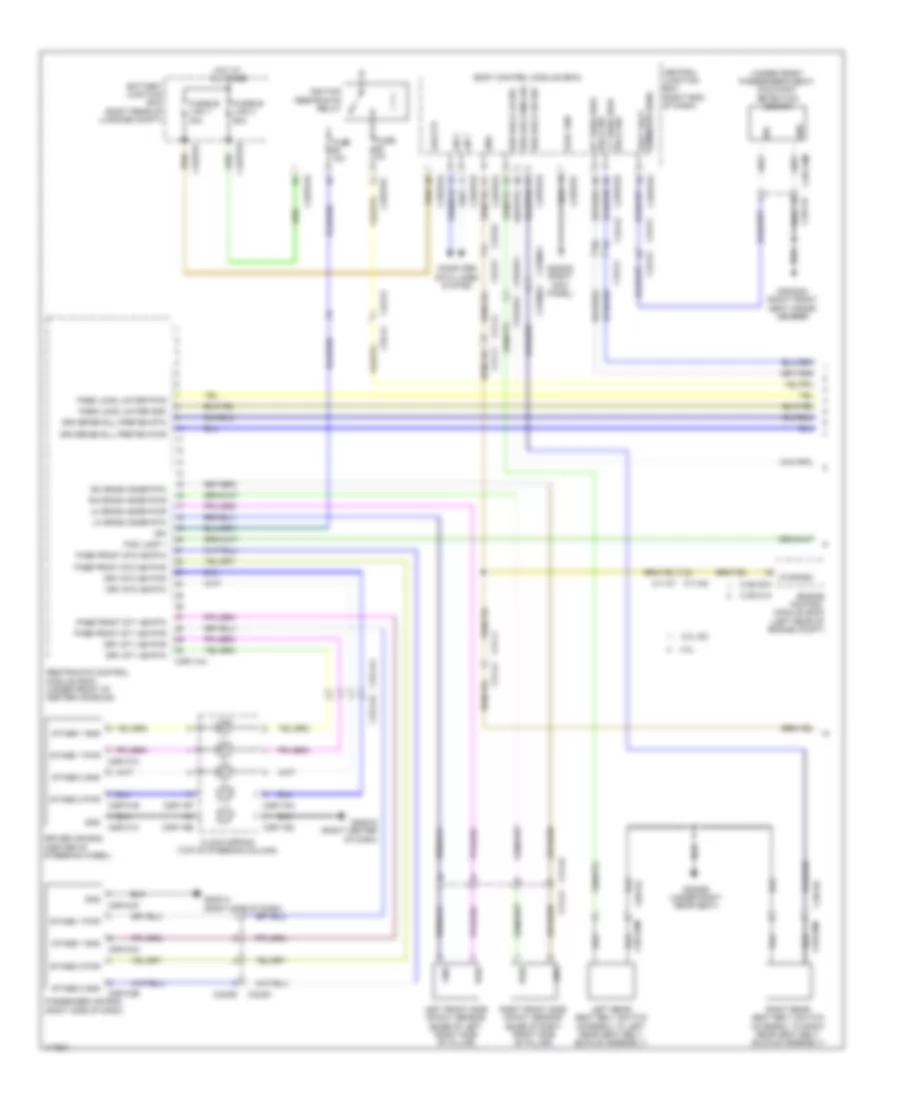
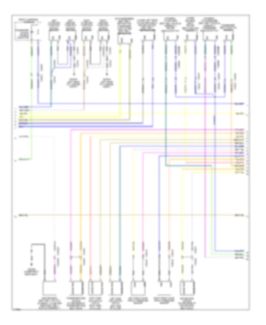
ELECTRONIC POWER STEERING Electronic Power Steering Wiring Diagram for Land Rover Range Rover Sport SE 2014 List of elements for Electronic Power Steering Wiring Diagram for Land Rover Range Rover Sport SE 2014: 27 (right front of engine compt) g1d132 Auxiliary junction box (right rear of engine compt) C11-f2 c11-f1 C11-g1 C11-g2 C1bb01b C1bf01b C1cs05a C1cs05b C1cs05c Computer data lines system Engine junction box (right rear of engine compt) Fuse 5a Fusible link 4 150a Gnd Gnd a Hot at all times Hot w/ ignition relay energized Hs can h Hs can l Ign Pas a Power steering control module (on steering rack assembly) Red Steering wheel module Torque sensor (on steering rack assembly) Vbatt
ELECTRONIC SUSPENSION Air Suspension Wiring Diagram (1 of 2) for Land Rover Range Rover Sport SE 2014 List of elements for Air Suspension Wiring Diagram (1 of 2) for Land Rover Range Rover Sport SE 2014: 69 (behind right brake light) right rear accelerometer (left front wheelwell, on frame rail) left front accelerometer (left rear wheelwell) left rear height sensor (on left rear shock absorber assembly) left rear damper solenoid (on right rear shock absorber assembly) right rear damper solenoid (right rear wheelwell) right rear height sensor Body control module (bcm) C2bp01e C2bp01f C2bp01g C31-a1 C31-a2 C31-f1 C31-f2 C31-j1 C31-j2 C31-l1 C31-l2 C33-y2 c33-y1 C44-b1 C44-b2 C44-b2 c44-b1 C4cl14d C4cl14e Central junction box (right end of dash) Computer data lines system Damper fl pos Damper fr pos Damper rl pos Damper rr pos Fl hgt 5v Fl hgt grd Fl hgt sig Fr hgt 5v Fr hgt gnd Fr hgt sig Fuse G4d351 (right rear of luggage compt) Gnd Hot w/ ignition relay energized Hs can h (ch) Hs can h (pt) Hs can l (ch) Hs can l (pt) Ign Integrated suspension control module (behind right rear quarterpanel) Left front damper solenoid (on left front shock absorber assembly) Left front height sensor (left front wheelwell) Pwr Right front accelerometer (right front wheelwell on frame rail) Right front damper solenoid (on right front shock absorber assembly) Right front height sensor (right front wheelwell) Rl hgt 5v Rl hgt gnd Rl hgt sig Rr hgt 5v Rr hgt gnd Rr hgt sig Sig Va fl 5v Va fl gnd Va fl sig Va fr 5v Va fr gnd Va fr sig Va rr 5v Va rr gnd Va rr sig Vbatt cvd Air Suspension Wiring Diagram (2 of 2) for Land Rover Range Rover Sport SE 2014 List of elements for Air Suspension Wiring Diagram (2 of 2) for Land Rover Range Rover Sport SE 2014: 54 (right side of luggage compt floor) rear valve block Air pressure sensor Air sus cont Air suspension cut off relay Air suspension relay C31-f1 C31-f2 C4br02a C4cl01a C4cl01c C4cl14a C4cl14b C4cl14c Comp rel pos Comp temp gnd Comp temp sig Comp v mon Computer data lines system Ex v pos F xv pos Fl cv pos Fr cv pos Front cross link valve Front valve block Fuse 10a Fuse 15a Fuse 5a Fusible link 7 60a G4d352 (right rear of luggage compt) Hot at all times Hs can h (pt) Hs can l (pt) Integrated suspension control module (behind right rear quarterpanel) Iso rel pos Left front corner valve Left rear corner valve Pressure 5v Pressure gnd Pressure sig R xv pos Rear cross link valve Rear junction box (behind right quarterpanel) Red Res v pos Reservoir valve Right front corner valve Right rear corner valve Rl cv pos Rr cv pos Self leveling suspension compressor (sls) (right rear of luggage compt floor) Sls compressor Sls exhaust valve Temperature compressor sensor Vbatt air Dynamic Response Wiring Diagram for Land Rover Range Rover Sport SE 2014 List of elements for Dynamic Response Wiring Diagram for Land Rover Range Rover Sport SE 2014: 79 (under left side of vehicle) lower lateral accelerometer C1bb01b C1cl41a C1cl41b C1cl41c C1cl41d C1cl41e C1cl41f C1cl41g C1cl41h C1cl41j C31-e1 C31-e2 C31-f1 C31-f2 C31-m1 C31-m2 C31-n1 C31-n2 C31-p1 C31-p2 C3cl54c C3cl54d C3cl54e Computer data lines system Dynamic response control module (left "a" pillar) Dynamic response valve block (under left side of vehicle) Engine junction box (right rear of engine compt) Faprvpistn pos Faprvrod pos Fapsnspistn 5v Fapsnspistn gnd Fapsnspistn sig Fapsnsrod 5v Fapsnsrod gnd Fapsnsrod sig Fuse 15a Fuse 5a G2d233 (left kick panel) Gnd Hot at all times Hot w/ ignition relay energized Hs can h (ch) Hs can h (pt) Hs can l (ch) Hs can l (pt) Ign Latacclwr 5v Latacclwr gnd Latacclwr sig Lataccupr 5v Lataccupr gnd Lataccupr sig Pcv 5v Pcv pos Pcvpsns gnd Pcvpsns sig Piston side front actuator pressure regulating valve Piston side front actuator pressure sensor Piston side rear actuator pressure regulating valve Piston side rear actuator pressure sensor Pressure control valve Pressure control valve pressure sensor Raprvpistn pos Raprvrod pos Rapsndpistn 5v Rapsndrod 5v Rapsndrod sig Rapsnspistn gnd Rapsnspistn sig Rapsnsrod gnd Rod side front actuator pressure regulating valve Rod side front actuator pressure sensor Rod side rear actuator pressure regulating valve Rod side rear actuator pressure sensor Safety control valve Scv pos Upper accelerometer (under front center headliner) Vbatt
ENGINE PERFORMANCE
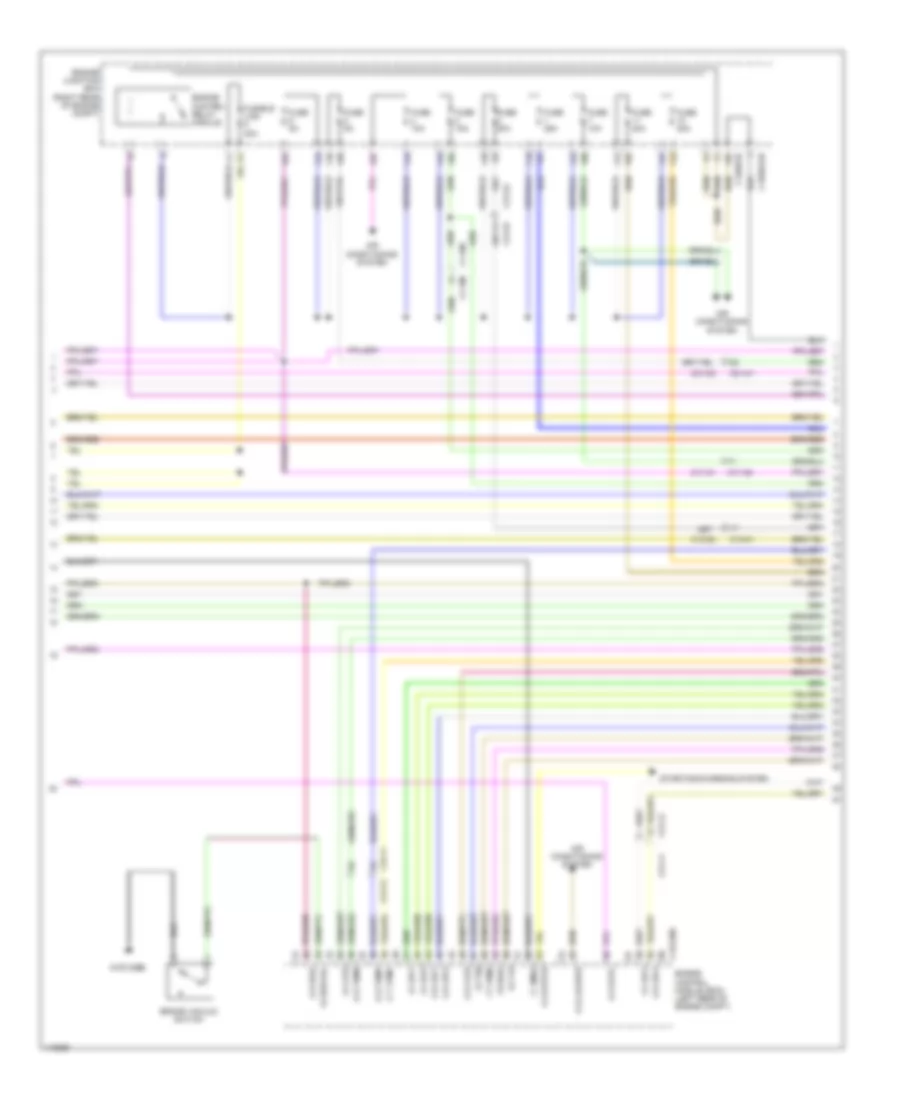
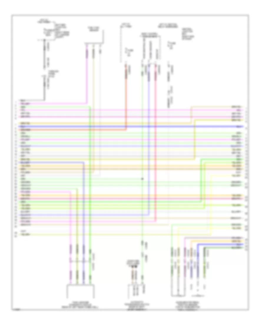
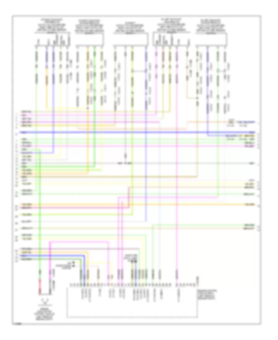
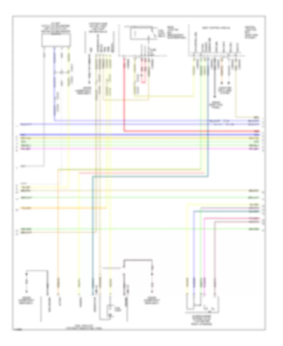
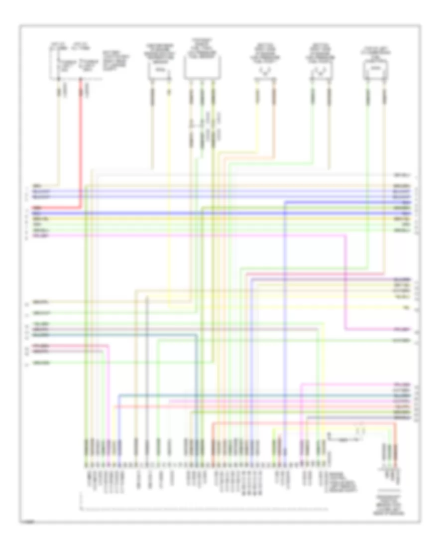
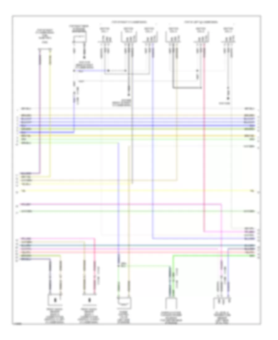
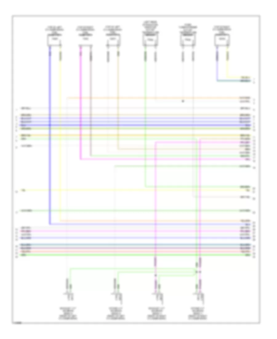
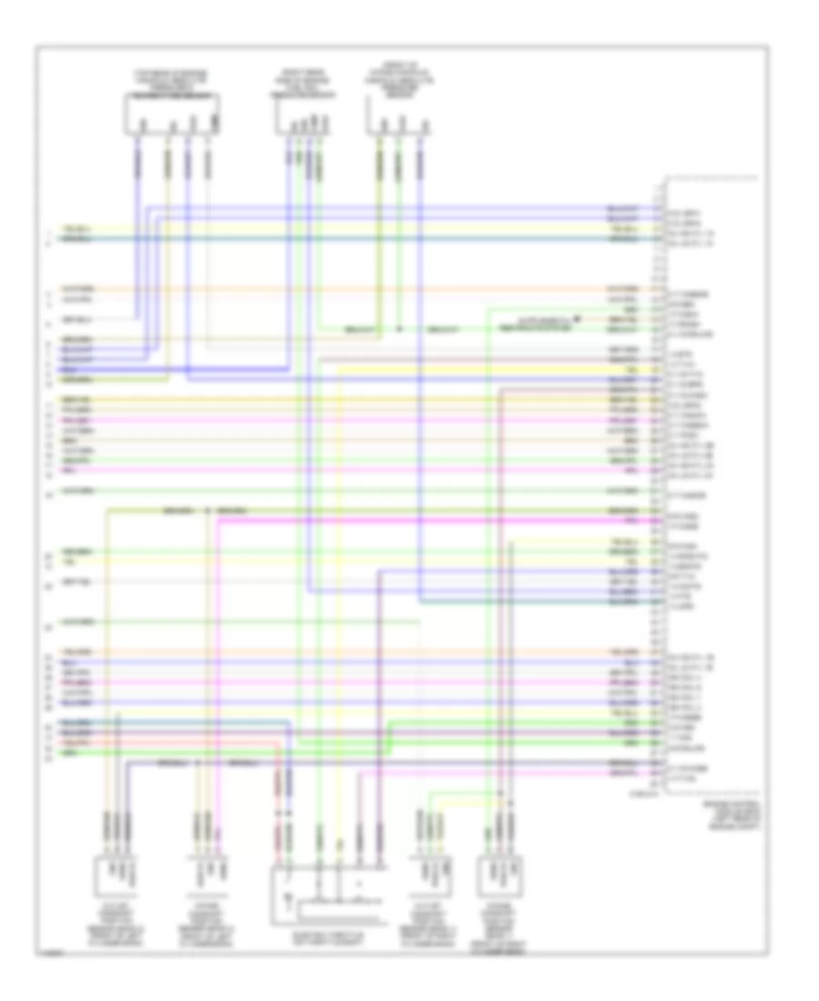
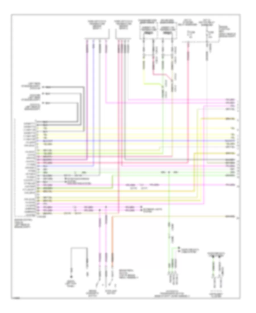
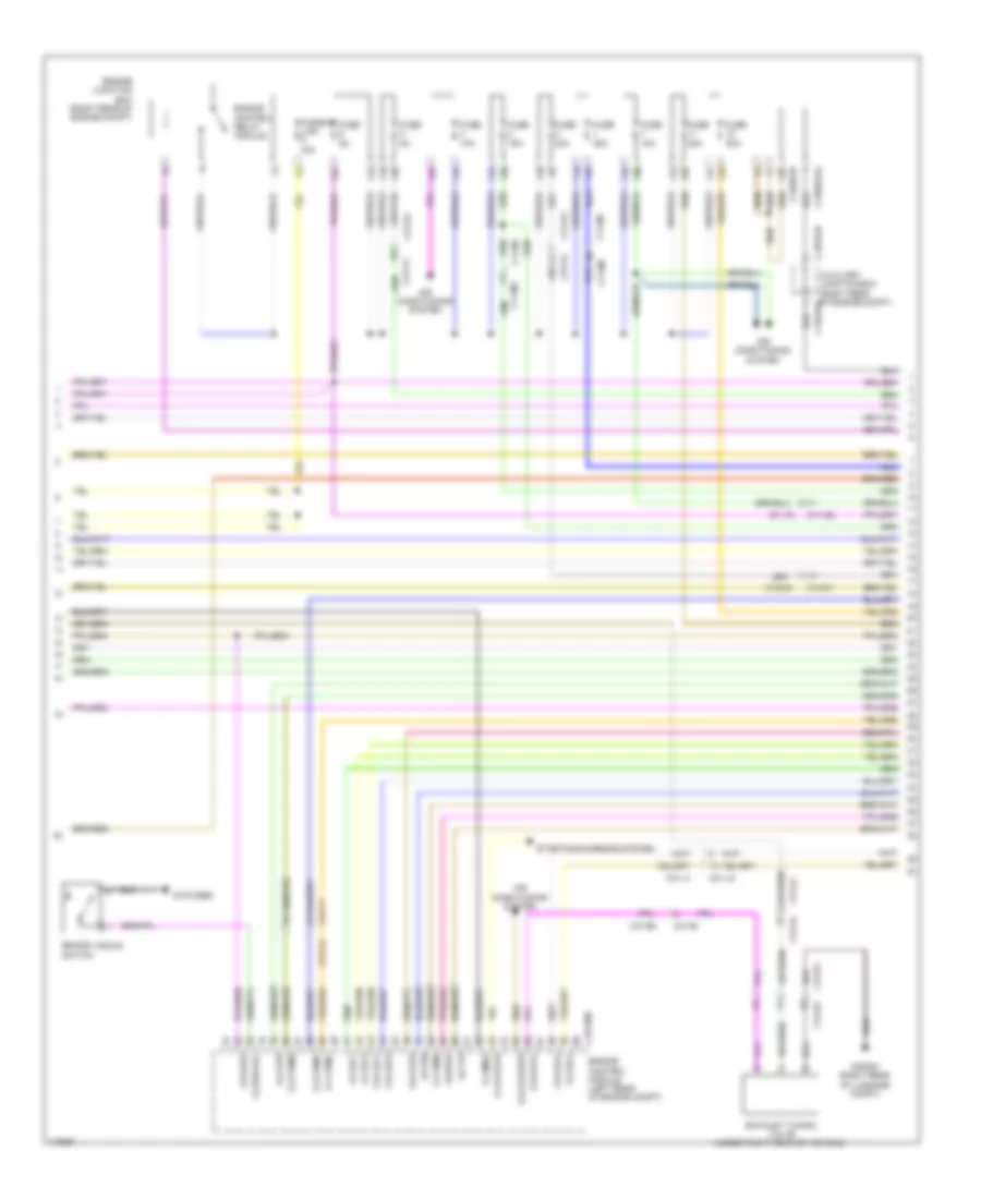
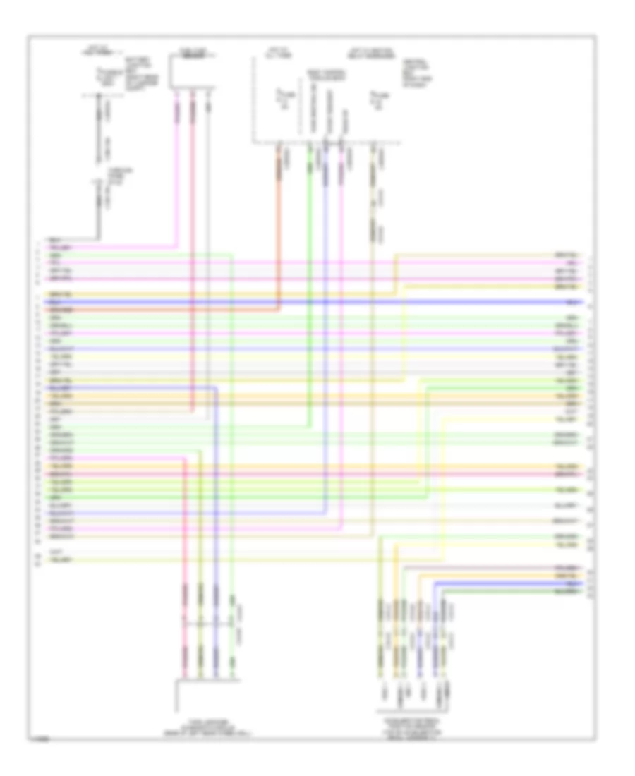
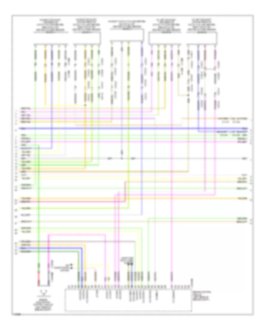
3.0L 3.0L, Engine Performance Wiring Diagram (1 of 9) for Land Rover Range Rover Sport SE 2014 List of elements for 3.0L, Engine Performance Wiring Diagram (1 of 9) for Land Rover Range Rover Sport SE 2014: 78 (left rear of engine compt) g1d121ar Ambient air temperature sensor Brake diagnostic Brake pedal switch (top of brake pedal assembly) C1bboib C1e120b C2mc01a C31-a1 C31-a2 C31-e1 C31-e2 C31-f1 C31-f2 C31-j1 C31-j2 C31-l1 C31-l2 C3a-a1 C3a-a2 C3b-a1 C3b-a2 C44-b1 C44-b2 Computer data lines system Driver side door mirror Engine control module (ecm) (left rear of engine compt) Engine junction box (right rear of engine compt) Exhaust tuning valve (under right rear of vehicle) Exterior lights system Fuse 10a Fuse 5a G g batt1 G g batt2 G g batt3 G r ams1 G r ats G1d121al (left rear of engine compt) G1d121bs (left rear of engine compt) G2d233 (left kick panel) G4d351 (right rear of luggage compt) Gnd Hot w/ ignition relay energized Hot w/ starter relay energized Hs can h Hs can l I a ats I a iats1 I a iats2 I a lscp1 I a lscp2 I a lsvn1 I a lsvn2 I f ams1 I f fqs I s brkos I s brksw I s tnsw I t t50r Instrument cluster Mass air flow & temperature sensor (bank 1) Mass air flow & temperature sensor (bank 2) O r lsvg1 O r lsvg2 O s lsfh3 O s strt3l O s tdmp O t eclg2 O t lshup1 Outh Outl Passenger side door mirror Starting/charging system cooling fans system Stop lamp switch Switch V v bat 1r V v bat 2r V v bat 3r Vbatt 3.0L, Engine Performance Wiring Diagram (2 of 9) for Land Rover Range Rover Sport SE 2014 List of elements for 3.0L, Engine Performance Wiring Diagram (2 of 9) for Land Rover Range Rover Sport SE 2014: 47 Air conditioning system Brake vacuum switch C11-m1 C11-m2 C13-c1 C13-c2 C1bb01ab C1bb01b C1e120b C31-f1 C31-f2 C31-j1 C31-j2 C31-k1 C31-k2 Engine control module (ecm) (left rear of engine compt) Engine control relay module Engine junction box (right rear of engine compt) Fuse 10a Fuse 15a Fuse 20a Fuse 25a Fuse 5a Fusible link 40a G r df01 G r flps G r lsf1 G r lsf3 G r lsf4 G1d123bs I a flps I a lsf1 I a lsf3 I a lsf4 I f ams2 I s brkvac I s t15 I s t50 I s wak I t fpmd O s cacwpr O s expl O s strth O s tdmh O s tdmv O t fpmc Starting/charging system 3.0L, Engine Performance Wiring Diagram (3 of 9) for Land Rover Range Rover Sport SE 2014 List of elements for 3.0L, Engine Performance Wiring Diagram (3 of 9) for Land Rover Range Rover Sport SE 2014: 38 Accelerator pedal position sensor (top of accelerator pedal assembly) Automatic transmission switch (base of shift lever assembly) Battery junction box (right rear of luggage compt) Body control module (bcm) C1dc13ab C2bp01e C2bp01f C2bp01g C31-f1 C31-f2 C31-j1 C31-j2 C31-k1 C31-k2 C31-l1 C31-l2 C32-m1 C32-m2 C3bp01f C3dc13a C44-d1 C44-d2 C4bf01j Central junction box (right end of dash) Computer data lines system Crank request Fuel flex sensor Fuse 5a Fusible link 1 250a Hot at all times Hot w/ ignition relay energized Hs can h Hs can l P/n sig Park neutral sig Tank leakage diagnostic module (rear of left rear wheelwell) Through panel stud Wake up 3.0L, Engine Performance Wiring Diagram (4 of 9) for Land Rover Range Rover Sport SE 2014 List of elements for 3.0L, Engine Performance Wiring Diagram (4 of 9) for Land Rover Range Rover Sport SE 2014: 50 (in left exhaust, downstream of catalytic converter) left post catalyst heated oxygen sensor (bank 2) (in left exhaust, upstream of catalytic converter) left pre catalyst heated oxygen sensor (bank 2) (in right catalytic converter) right mid catalyst heated oxygen sensor (bank 1) (in right exhaust, downstream of catalytic converter) right post catalyst heated oxygen sensor (bank 1) (in right exhaust, upstream of catalytic converter) right pre catalyst heated oxygen sensor (bank 1) Air conditioning system B d canh1 B d canl1 C11-m1 C11-m2 C11-m2 c11-m1 C13-c1 C13-c2 C13-d1 C13-d2 C1e120b C1e346 C1e346m C31-a1 C31-a2 C31-f1 C31-f2 C31-j1 C31-j2 C31-k1 C31-k2 Computer data lines system Ctrl Current pmp Engine control module (ecm) (left rear of engine compt) Engine cooling fan control module (left rear of engine compt) G r app1 G r app2 G r lsf2 I a app1 I a app2 I a lsf2 I t fss Nernst v O s mrly O s pcf O t evf O t lshup2 O v 5vapp1 O v 5vapp2 O v 5vflps Pmp current Red Sply Virtual gnd 3.0L, Engine Performance Wiring Diagram (5 of 9) for Land Rover Range Rover Sport SE 2014 List of elements for 3.0L, Engine Performance Wiring Diagram (5 of 9) for Land Rover Range Rover Sport SE 2014: 47 (in left catalytic converter) left mid catalyst heated oxygen sensor (bank 2) (top right side of fuel tank) fuel pump driver module Active Body control module C11-m1 C11-m2 C13-c1 C13-c2 C2bp01d C2bp01e C2bp01f C2bp01g C31-a1 C31-a2 C31-k1 C31-k2 C4br02a C4br02b C4mc11a C4mc11c Central junction box (right end of dash) Computer data lines system Diagnostic o/p Esd ground F/p control gnd Fuel pump Fuel pump relay Fuel tank unit (top right side of fuel tank) Fuse 30a G2d238 (right kick panel) G3d389 (under right rear seat) Gnd Ground Hs can h Hs can l Motor + Motor - Passive Pwm Pwr Pwr gnd Rear junction box (behind right quarterpanel) Red Sender rtn Sensor gnd Supercharger bypass valve (top center front of engine) Vbatt3 3.0L, Engine Performance Wiring Diagram (6 of 9) for Land Rover Range Rover Sport SE 2014 List of elements for 3.0L, Engine Performance Wiring Diagram (6 of 9) for Land Rover Range Rover Sport SE 2014: 52 (bottom right side of engine) high pressure fuel pump 1 (bottom right side of engine) high pressure fuel pump 2 (center rear of engine) engine coolant temperature sensor (top of left cylinder bank) fuel injector 6 (top right side of fuel tank) low pressure fuel sensor Battery junction box (right rear of luggage compt) C1e121a C31-f1 C31-f2 C31-k1 C31-k2 C4bf01c C4bf01f Crankshaft position sensor (ckp) (lower left rear of engine) Engine control module (ecm) (left rear of engine compt) Fusible link 5 250a Fusible link 7 40a G r bps G r cbpp G r crs G r engts G r imps G r ocs Gnd Hot at all times I a bps I a cbpp I a ks1a I a ks1b I a ks2a I a ks2b I a railps I f crs I p casea Ign coil 2 Ign coil 5 Inj hs cyl 2a Inj hs cyl 3b Inj ls cyl 2a Inj ls cyl 3b Nca O p fscvh1 O p fscvh2 O p fscvl1 O p fscvl2 O t cbppos O t tvapos O v 5vcbpp O v crs Pwr 5v Red Sens 3.0L, Engine Performance Wiring Diagram (7 of 9) for Land Rover Range Rover Sport SE 2014 List of elements for 3.0L, Engine Performance Wiring Diagram (7 of 9) for Land Rover Range Rover Sport SE 2014: 28 (top of left cylinder bank) (top of right cylinder bank) (top of right cylinder bank) fuel injector 2 (top right rear of engine) capacitor C11-af C11-an C11-m1 C11-m2 C11-m2 c11-m1 Ctrl Front knock sensor (bank 1) (under intake manifold, in right cylinder bank) Front knock sensor (bank 2) (under intake manifold, in left cylinder bank) G1d1100e G1d1101e (rear of right cylinder bank) G1d198e (front of right cylinder bank) Gnd Ign Ignition coil 1 Ignition coil 2 Ignition coil 3 Ignition coil 4 Ignition coil 5 Ignition coil 6 Manifold intake tuning/symposer solenoid (top center rear of engine) Oil level & temperature sensor (left rear of oil pan) Purge control valve (left side of engine) Sig Vref 3.0L, Engine Performance Wiring Diagram (8 of 9) for Land Rover Range Rover Sport SE 2014 List of elements for 3.0L, Engine Performance Wiring Diagram (8 of 9) for Land Rover Range Rover Sport SE 2014: 12 (left rear of radiator) radiator outlet temperature sensor (top of left cylinder bank) fuel injector 4 (top of left cylinder bank) fuel injector 5 (top of right cylinder bank) fuel injector 1 (top of right cylinder bank) fuel injector 3 Ctrl Exhaust vvt solenoid (bank 1) (front of right cylinder bank) Exhaust vvt solenoid (bank 2) (front of left cylinder bank) Fixed turbocharger outlet temperature sensor Intake vvt solenoid (bank 1) (front of right cylinder bank) Intake vvt solenoid (bank 2) (front of left cylinder bank) Sply 3.0L, Engine Performance Wiring Diagram (9 of 9) for Land Rover Range Rover Sport SE 2014 List of elements for 3.0L, Engine Performance Wiring Diagram (9 of 9) for Land Rover Range Rover Sport SE 2014: 60 (front of intake manifold) manifold absolute pressure sensor (right rear side of engine) fuel rail pressure sensor (top rear of engine) manifold absolute pressure & temperature sensor C1e121a Electric throttle (on throttle body) Engine control module (ecm) (left rear of engine compt) G r cas1 G r cas2 G r railps G r sen G r tva Gnd I a bts I a cacts I a engts I a fts I a imps I a radwts I a tva1 I a tva2 I f crash I p caseb I p casia I p casib I t ocs Ign coil 1 Ign coil 3 Ign coil 4 Ign coil 6 Inj hs cyl 1a Inj hs cyl 1b Inj hs cyl 2b Inj hs cyl 3a Inj ls cyl 1a Inj ls cyl 1b Inj ls cyl 2b Inj ls cyl 3a Intake camshaft position sensor (bank 1) (front of right cylinder bank) Intake camshaft position sensor (bank 2) (front of left cylinder bank) O s ass O s lsfh1 O s lsfh2 O s lsfh4 O t caseca O t casecb O t casica O t casicb O t pcsv O v 5vbps O v 5vcasa O v 5vcasb O v 5vrailps O v 5vtva Outlet camshaft position sensor (bank 1) (front of right cylinder bank) Outlet camshaft position sensor (bank 2) (front of left cylinder bank) Pwr 5v Sens Sig Temp Vref
5.0L SC 5.0L SC, Engine Performance Wiring Diagram (1 of 9) for Land Rover Range Rover Sport SE 2014 List of elements for 5.0L SC, Engine Performance Wiring Diagram (1 of 9) for Land Rover Range Rover Sport SE 2014: 75 (left rear of engine compt) g1d121ar Ambient air temperature sensor Automatic transmission switch (base of shift lever assembly) Brake diagnostic switch Brake pedal switch (top of brake pedal assembly) C1bboib C1e120b C2mc01a C31-a1 C31-a2 C31-f1 C31-f2 C31-j1 C31-j2 C31-l1 C31-l2 C32-m1 C32-m2 C3a-a1 C3a-a2 C3b-a1 C3b-a2 Computer data lines system Driver side door mirror Engine control module (left rear of engine compt) Engine junction box (right rear of engine compt) Exterior lights system Fuse 10a Fuse 5a G-g-batt1 G-g-batt2 G-g-batt3 G-r-ams1 G-r-ats G1d121al (left rear of engine compt) G1d121bs (left rear of engine compt) G2d233 (left kick panel) Gnd Hot w/ ignition relay energized Hot w/ starter relay energized Hs can h Hs can l I-a-ats I-a-iats1 I-a-iats2 I-a-lscp1 I-a-lscp2 I-a-lsvn1 I-a-lsvn2 I-f-ams1 I-f-fqs I-s-brkos I-s-brksw I-s-tnsw I-t-t50r Instrument cluster Mass air flow & temperature sensor (bank 1) Mass air flow & temperature sensor (bank 2) O s strtl O-r-lsvg1 O-r-lsvg2 O-s-lsfh3 O-s-tdmp O-t-eclg2 O-t-lshup1 Outh Outl P/n sig Passenger side door mirror Starting/charging system cooling fans system Stop lamp switch V-v-bat-1r V-v-bat-2r V-v-bat-3r Vbatt 5.0L SC, Engine Performance Wiring Diagram (2 of 9) for Land Rover Range Rover Sport SE 2014 List of elements for 5.0L SC, Engine Performance Wiring Diagram (2 of 9) for Land Rover Range Rover Sport SE 2014: 58 Air conditioning system Auxiliary junction box (right rear of engine compt) c1bf01a Brake vacuum C11-m1 C11-m2 C13-c1 C13-c2 C1bb01aa C1bb01b C1bf01h C1e120b C31-a1 C31-a2 C31-e1 C31-e2 C31-f1 C31-f2 C31-j1 C31-j2 C31-k1 C31-k2 C44-b1 C44-b2 Engine control module (left rear of engine compt) Engine control relay module Engine junction box (right rear of engine compt) Exhaust tuning valve (under right rear of vehicle) Fuse 10a Fuse 15a Fuse 20a Fuse 25a Fuse 5a Fusible link 40a G-r-df01 G-r-flps G-r-lsf1 G-r-lsf3 G-r-lsf4 G1d123bs G4d351 (right rear of luggage compt) I s brkvac I-a-flps I-a-lsf1 I-a-lsf3 I-a-lsf4 I-f-ams2 I-s-t15 I-s-t50 I-s-wak I-t-fpmd O s strth O-s-cacwpr O-s-expl O-s-tdmh O-s-tdmv O-t-fpmc Starting/charging system Switch 5.0L SC, Engine Performance Wiring Diagram (3 of 9) for Land Rover Range Rover Sport SE 2014 List of elements for 5.0L SC, Engine Performance Wiring Diagram (3 of 9) for Land Rover Range Rover Sport SE 2014: 36 Accelerator pedal position sensor (top of accelerator pedal assembly) Battery junction box (right rear of luggage compt) Body control module (bcm) C1dc13a C2bp01e C2bp01f C2bp01g C31-f1 C31-f2 C31-j1 C31-j2 C31-k1 C31-k2 C31-l1 C31-l2 C3dc13a C44-d1 C44-d2 C4bf01j Central junction box (right end of dash) Demand 1 Demand 2 Fuel flex sensor Fuse 5a Fusible link 1 250a Gnd 1 Gnd 2 Hot at all times Hot w/ ignition relay energized Park neutral sig Start request Tank leakage diagnostic module (rear of left rear wheelwell) Through panel stud Vref 1 Vref 2 Wake up 5.0L SC, Engine Performance Wiring Diagram (4 of 9) for Land Rover Range Rover Sport SE 2014 List of elements for 5.0L SC, Engine Performance Wiring Diagram (4 of 9) for Land Rover Range Rover Sport SE 2014: 44 (in left exhaust, downstream of catalytic converter) post catalyst heated oxygen sensor (bank 2) (in left exhaust, upstream of catalytic converter) pre catalyst heated oxygen sensor (bank 2) (in right catalytic converter) mid catalyst heated oxygen sensor (bank 1) (in right exhaust, downstream of catalytic converter) post catalyst heated oxygen sensor (bank 1) (in right exhaust, upstream of catalytic converter) pre catalyst heated oxygen sensor (bank 1) Air conditioning system B-d-canh1 B-d-canl1 C11-m1 C11-m2 C11-m2 c11-m1 C13-c1 C13-c2 C13-d1 C13-d2 C1e120b C1e346 C1e346m C31-a1 C31-a2 C31-f1 C31-f2 C31-j1 C31-j2 C31-k1 C31-k2 Computer data lines system Engine control module (left rear of engine compt) Engine cooling fan control module (left rear of engine compt) G-r-app1 G-r-app2 G-r-lsf2 I-a-app1 I-a-app2 I-a-lsf2 I-t-fss O-s-mrly O-s-pcf O-t-evf O-t-lshup2 O-v-5vapp1 O-v-5vapp2 O-v-5vflps Red 5.0L SC, Engine Performance Wiring Diagram (5 of 9) for Land Rover Range Rover Sport SE 2014 List of elements for 5.0L SC, Engine Performance Wiring Diagram (5 of 9) for Land Rover Range Rover Sport SE 2014: 51 (in left catalytic converter) mid catalyst heated oxygen sensor (bank 2) (top right side of fuel tank) (top right side of fuel tank) fuel pump driver module Active Body control module C11-m1 C11-m2 C13-c1 C13-c2 C2bp01d C2bp01e C2bp01f C2bp01g C31-a1 C31-a2 C31-k1 C31-k2 C4br02a C4br02b C4mc11a C4mc11c Central junction box (right end of dash) Computer data lines system Diagnostic o/p Esd gnd F/p control gnd Fuel pump Fuel pump relay Fuel tank unit Fuse 30a G2d238 (right kick panel) G3d389 (under right rear seat) Gnd Hs can h Hs can l Motor + Motor - Passive Pwm Pwr Pwr gnd Rear junction box (behind right quarterpanel) Rear knock sensor (bank 1) (under intake manifold, in right cylinder bank) Rear knock sensor (bank 2) (under intake manifold, in left cylinder bank) Red Sender rtn Sensor gnd Sig Supercharger bypass valve (top center front of engine) Tps 5v Vbatt3 5.0L SC, Engine Performance Wiring Diagram (6 of 9) for Land Rover Range Rover Sport SE 2014 List of elements for 5.0L SC, Engine Performance Wiring Diagram (6 of 9) for Land Rover Range Rover Sport SE 2014: 61 (bottom right side of engine) (bottom right side of engine) high pressure fuel pump 1 (center rear of engine) engine coolant temperature (ect) sensor (top of left cylinder bank) fuel injector 3 (top of right cylinder bank) fuel injector 7 Battery junction box (right rear of luggage compt) C11af C11an C1e120a C31-f1 C31-f2 C31-k1 C31-k2 C4bf01c C4bf01f Crankshaft position sensor (lower left rear of engine) Engine control module (left rear of engine compt) Fusible link 5 250a Fusible link 7 40a G-r-bps G-r-cbpp G-r-crs G-r-imps G-r-ocs High pressure fuel pump 2 Hot at all times I-a-bps I-a-cbpp I-a-ks1a I-a-ks1b I-a-ks2a I-a-ks2b I-a-ks3a I-a-ks3b I-a-ks4a I-a-ks4b I-a-railps I-f-crs I-p-casea Ign coil 2 Ign coil 4 Ign coil 6 Ign coil 8 Inj hs cyl 1b Inj hs cyl 3a Inj hs cyl 3b Inj ls cyl 1b Inj ls cyl 3a Inj ls cyl 3b Low fuel pressure sensor Nca O-p-fscvh1 O-p-fscvh2 O-p-fscvl1 O-p-fscvl2 O-s-casp2 O-t-cbppos O-t-tvapos O-v-5vcbpp O-v-crs Red 5.0L SC, Engine Performance Wiring Diagram (7 of 9) for Land Rover Range Rover Sport SE 2014 List of elements for 5.0L SC, Engine Performance Wiring Diagram (7 of 9) for Land Rover Range Rover Sport SE 2014: 26 (top of left cylinder bank) (top of right cylinder bank) (top of right cylinder bank) fuel injector 5 (top right rear of engine) capacitor C11af C11an C11m1 C11m2 Camshaft profile switching solenoid (bank 1) Camshaft profile switching solenoid (bank 2) Front knock sensor (bank 1) (under intake manifold, in right cylinder bank) Front knock sensor (bank 2) (under intake manifold, in left cylinder bank) G1d1100 G1d198 (front of right cylinder bank) Gd1101 Ignition coil 1 Ignition coil 2 Ignition coil 3 Ignition coil 4 Ignition coil 5 Ignition coil 6 Ignition coil 7 Ignition coil 8 Manifold intake tuning or symposer solenoid (top center rear of engine) Oil level & temperature sensor (left rear of oil pan) Purge control valve (left side of engine) 5.0L SC, Engine Performance Wiring Diagram (8 of 9) for Land Rover Range Rover Sport SE 2014 List of elements for 5.0L SC, Engine Performance Wiring Diagram (8 of 9) for Land Rover Range Rover Sport SE 2014: 11 (left rear of radiator) radiator outlet temperature sensor (top center of engine) air charge temperature sensor (top of left cylinder bank) fuel injector 1 (top of left cylinder bank) fuel injector 2 (top of left cylinder bank) fuel injector 4 (top of right cylinder bank) fuel injector 6 (top of right cylinder bank) fuel injector 8 Exhaust vvt solenoid (bank 1) (front of right cylinder bank) Exhaust vvt solenoid (bank 2) (front of left cylinder bank) Intake vvt solenoid (bank 1) (front of right cylinder bank) Intake vvt solenoid (bank 2) (front of left cylinder bank) 5.0L SC, Engine Performance Wiring Diagram (9 of 9) for Land Rover Range Rover Sport SE 2014 List of elements for 5.0L SC, Engine Performance Wiring Diagram (9 of 9) for Land Rover Range Rover Sport SE 2014: 59 (front of intake manifold) manifold absolute pressure sensor (right rear side of engine) fuel rail pressure sensor (top rear of engine) manifold absolute pressure & temperature sensor C1e120a Electric throttle unit (on throttle body) Engine control module (ecm) (left rear of engine compt) G-r-cas1 G-r-cas2 G-r-railps G-r-sen G-r-tva Gnd I-a-bts I-a-cacts I-a-fts I-a-imps I-a-radwts I-a-tva1 I-a-tva2 I-f-crash I-p-caseb I-p-casia I-p-casib I-t-ocs Ign coil 1 Ign coil 3 Ign coil 5 Ign coil 7 Inj hs cyl 1a Inj hs cyl 2a Inj hs cyl 2b Inj hs cyl 4a Inj hs cyl 4b Inj ls cyl 1a Inj ls cyl 2a Inj ls cyl 2b Inj ls cyl 4a Inj ls cyl 4b Intake camshaft position sensor (bank 1) (front of right cylinder bank) Intake camshaft position sensor (bank 2) (front of left cylinder bank) O-s-ass O-s-casp1 O-s-lsfh1 O-s-lsfh2 O-s-lsfh4 O-t-caseca O-t-casecb O-t-casica O-t-casicb O-t-pcsv O-v-5vbps O-v-5vcasa O-v-5vcasb O-v-5vrailps O-v-5vtva Out Outlet camshaft position sensor (bank 1) (front of right cylinder bank) Outlet camshaft position sensor (bank 2) (front of left cylinder bank) Vref
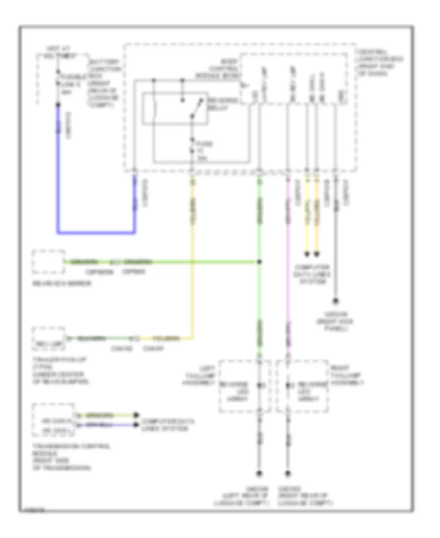
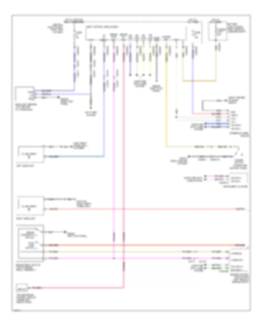
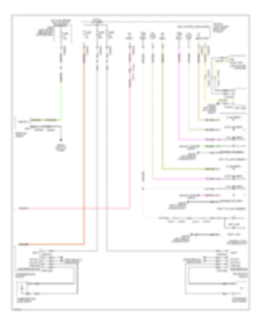
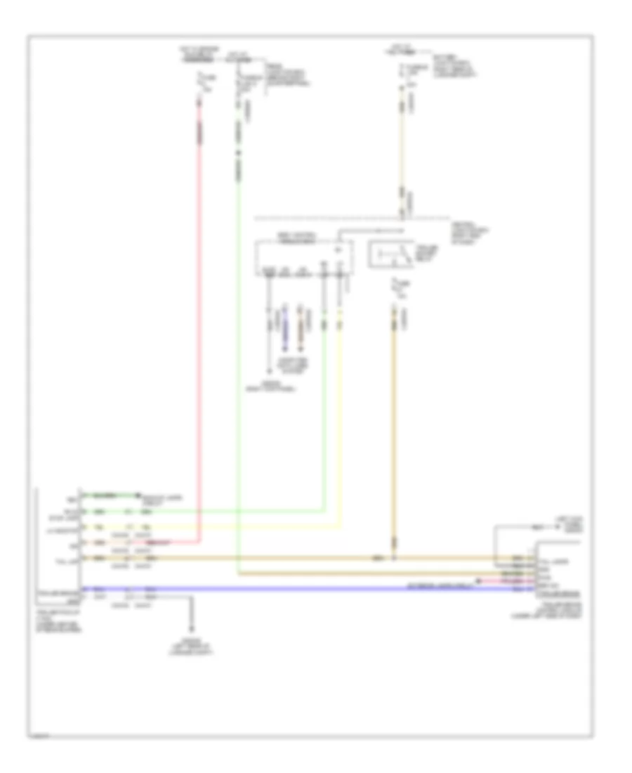
EXTERIOR LIGHTS Backup Lamps Wiring Diagram for Land Rover Range Rover Sport SE 2014 List of elements for Backup Lamps Wiring Diagram for Land Rover Range Rover Sport SE 2014: 35 40a Battery junction box (right rear of luggage compt) Body control module (bcm) C1bp01d C2bp01b C2bp01f C44-n1 C44-n2 C4bf01g C9pm05 C9pm05m Central junction box (right end of dash) Computer data lines system Fuse 10a Fusible link 6 G2d238 (right kick panel) G4d349 (left rear of luggage compt) G4d352 (right rear of luggage compt) Gnd Hot at all times Hs can h Hs can l Left taillamp assembly Lh rev lmp Lsd Ms can h Ms can l Rearview mirror Rev lmp Reverse led array Reverse relay Rh rev lmp Right taillamp assembly Trailer pick-up (7 pin) (under center of rear bumper) Transmission control module (right side of transmission) Exterior Lamps Wiring Diagram (1 of 2) for Land Rover Range Rover Sport SE 2014 List of elements for Exterior Lamps Wiring Diagram (1 of 2) for Land Rover Range Rover Sport SE 2014: 73 (left front wheelwell) g1d129br (right center of dash) g2d216 Anti-theft system B d can h1 B d can l1 Battery junction box (right rear of luggage compt) Body control module (bcm) Brake diag Brake diagnostic switch Brake pedal switch (top of brake pedal assembly) Brake sw Brk sw C1e120b C2bp01a C2bp01b C2bp01c C2bp01d C2bp01e C2bp01f C2bp01g C2mc01a C2me14 C2me14a C31-f1 C31-f2 C31-k1 C31-k2 C32-a1 C32-a2 C32-d1 C32-d2 C32-f1 C32-f2 C4bf01f Central junction box (right end of dash) Computer data lines system Di led array Elec gnd Engine control module (ecm) (left rear of engine compt) Fuse 10a Fuse 5a Fusible link 7 40a G1d131al (right front wheelwell) G2d215 (right center of dash) G2d233 (left kick panel) G2d238 (right kick panel) Gnd Hazard sw Hazard switch Hot at all times Hot w/ ignition relay energized Hs can h Hs can l I s brk sw I s brkos Instrument cluster Integrated control panel Left headlamp Lh di front Lin Lin 1 Lin 2 Lin 3 Ms can h Ms can l Pwr Rain/light sensor (top center of windshield) Right headlamp Sig Steering wheel module Stop lamp switch Trailer brake control module (under left side of dash) Vbatt Exterior Lamps Wiring Diagram (2 of 2) for Land Rover Range Rover Sport SE 2014 List of elements for Exterior Lamps Wiring Diagram (2 of 2) for Land Rover Range Rover Sport SE 2014: 66 Backup lamps circuit Body control module (bcm) C2bp01b C2bp01c C2bp01d C2bp01f C31-l2 c31-l1 C32-a2 c32-a1 C44-h1 C44-h2 C44-s2 c44-s1 C44-u1 C44-u2 C4br02a C4x201a C4x201b C9pm05 C9pm05m Capw02a Capw02b Cbpw04a Cbpw04b Central junction box (right end of dash) Chmsl pwr Chsml Computer data lines system Di led array Driver door module Driver side door mirror Fuse 10a Fuse 25a Fuse 5a G2d233 (left kick panel) G4d349 (left rear of luggage compt) G4d352 (right rear of luggage compt) Gnd High mounted stoplamp Hot at all times Hot w/ extended ignition relay energized Left lamp Left taillamp assembly Lh di rear Lh stop lamp License plate & tail door switch Mirr gnd Mirr sply Ms can h Ms can l Passenger door module Passenger side door mirror Posi lmp rr lh Posi lmp rr rh Rear junction box (behind right quarterpanel) Rearview mirror Reverse led array Rf filter Rh di front Rh di rear Rh stop lamp Right lamp Right taillamp assembly Side repeater Side repeater ind Stop led array Tail led array Vbatt Trailer Tow Wiring Diagram for Land Rover Range Rover Sport SE 2014 List of elements for Trailer Tow Wiring Diagram for Land Rover Range Rover Sport SE 2014: 42 (left kick panel) g2d233 10a Backup lamps circuit Battery junction box (right rear of luggage compt) Body control module (bcm) Brk sw C2bp01d C2bp01e C2bp01f C44-m1 c44-m2 C44-n2 c44-n1 C4bf01f C4br02a Central junction box (right end of dash) Computer data lines system Elec gnd Exterior lamps circuit Fuse Fuse 15a Fusible link 40a Fusible link 8 30a G2d238 (right kick panel) G4d349 (left rear of luggage compt) Gnd Hot at all times Hot w/ engine run relay energized Hs can h Hs can l Ign Lh id ind Lh ind/stop Pwr Rear junction box (behind right quarterpanel) Rev Rh di stop lamp Rh id lmp Tail lamps Tail lmp Trailer brake Trailer brake control module (under left side of dash) Trailer pick-up (7 pin) (under center of rear bumper) Trailer socket relay
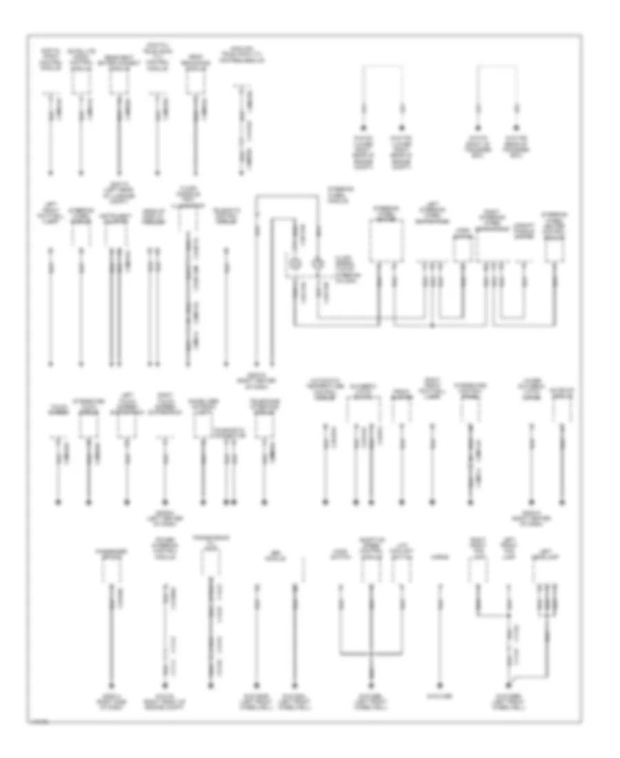
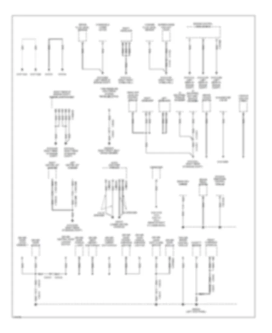
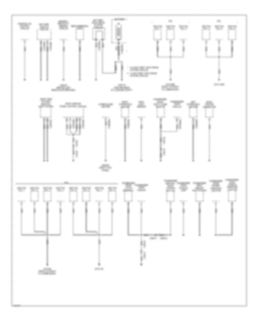
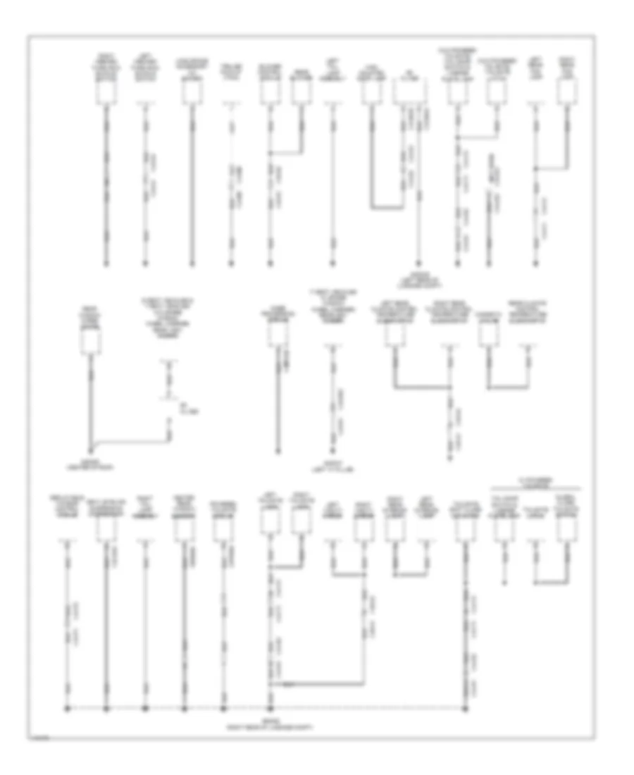
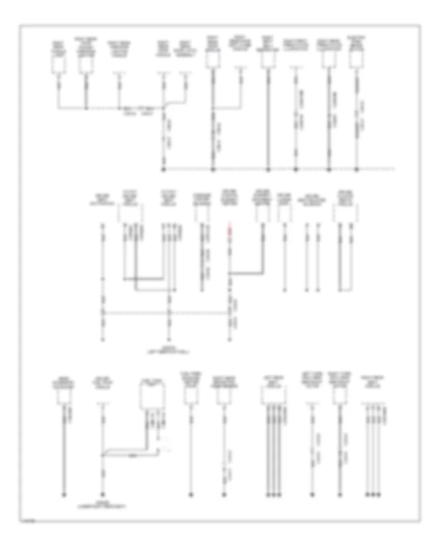
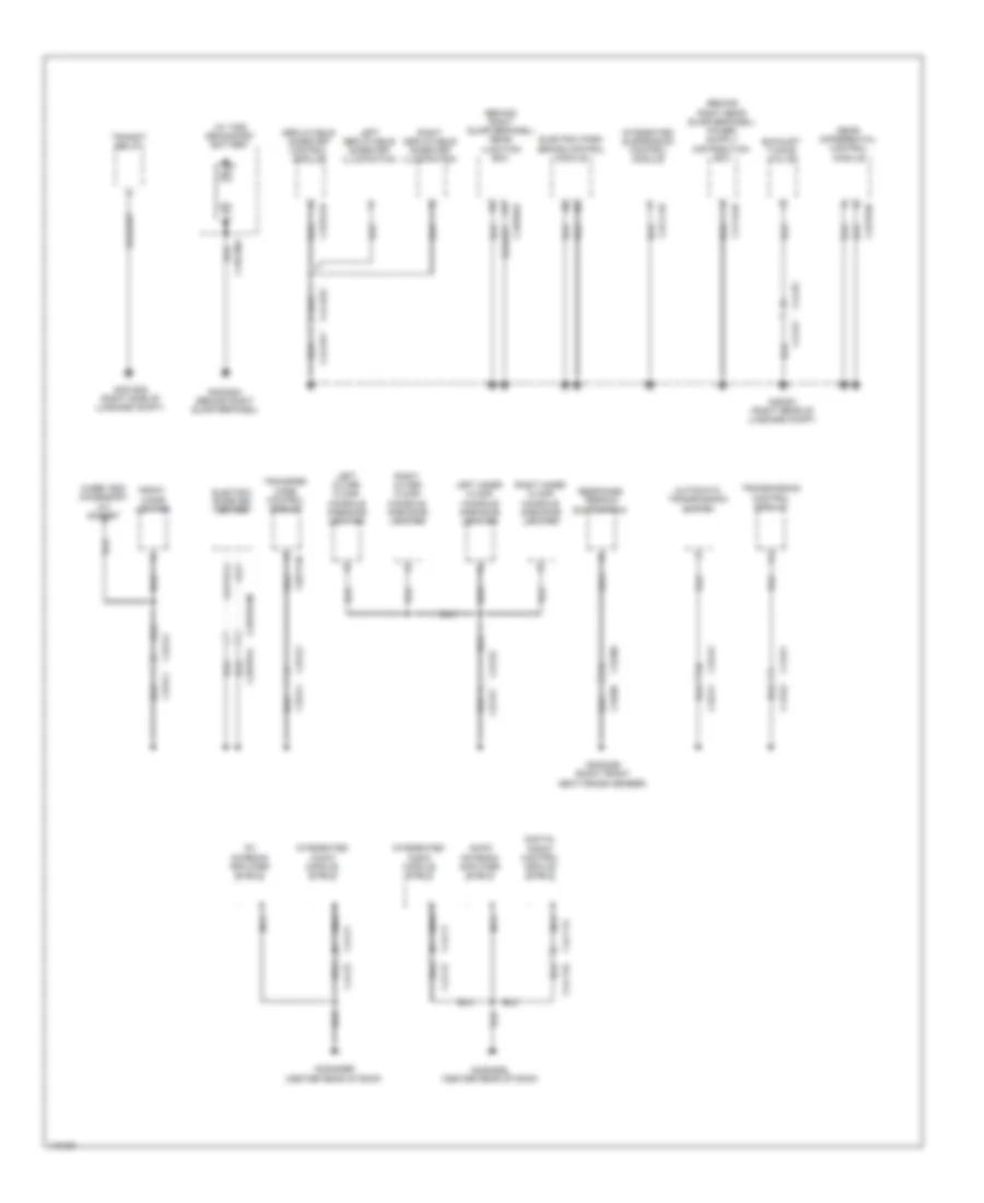
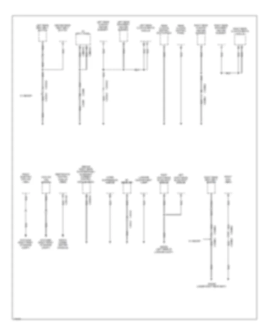
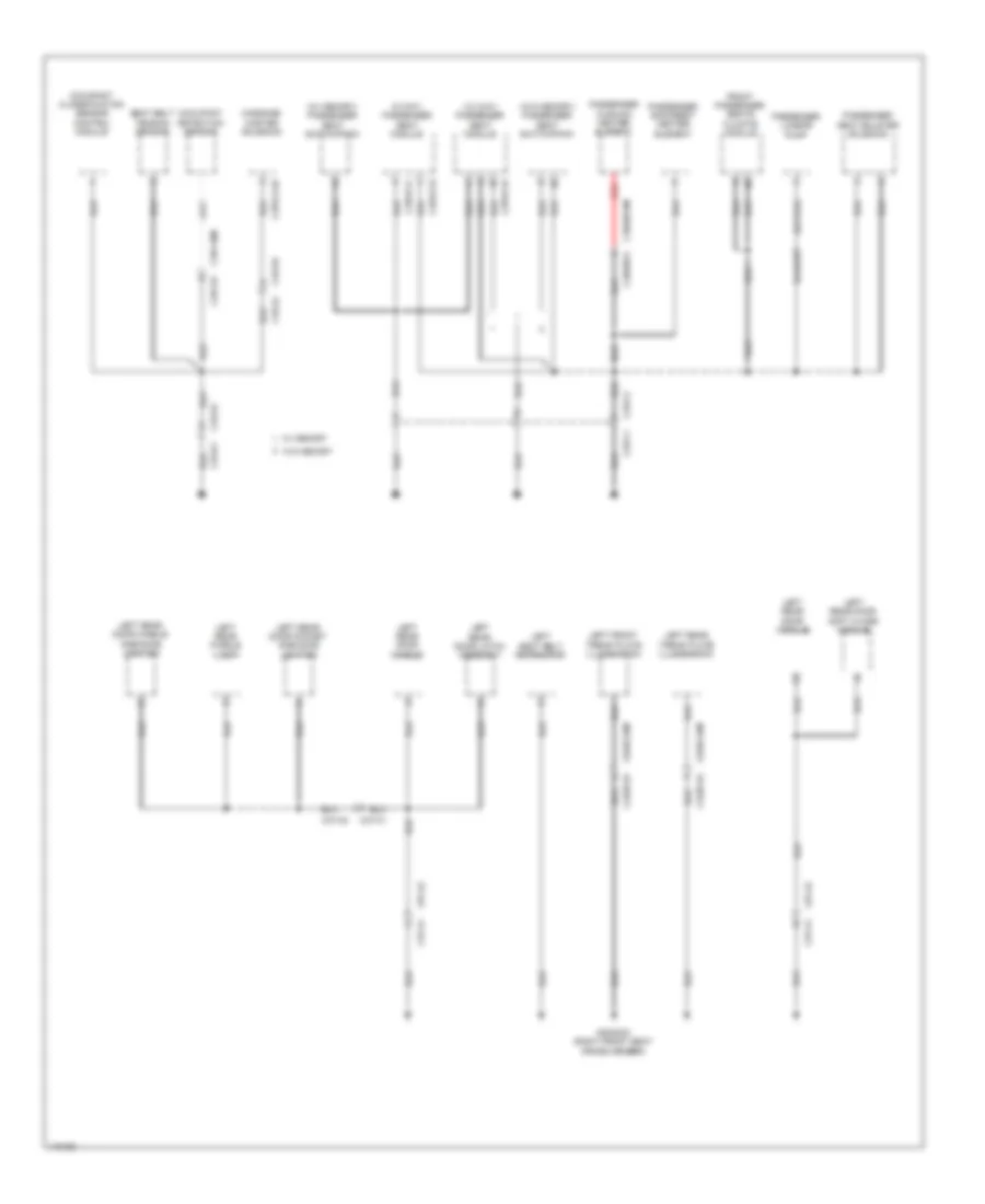
GROUND DISTRIBUTION Ground Distribution Wiring Diagram (1 of 8) for Land Rover Range Rover Sport SE 2014 List of elements for Ground Distribution Wiring Diagram (1 of 8) for Land Rover Range Rover Sport SE 2014: 90 (analog) television (tv) control module (digital) television (tv) control module Abs module Adaptive speed control module Automatic temperature control module C11-b2 c11-b1 C11-f1 C11-f2 C13-z1 C13-z2 C1cs05a C2h101a C2ln12 C2ln71a C2ln71am C2mc01a C2mc02a C2me03a C2me14a C2mm25a C2pr157 C2r103c C2r115b C2r115d C2r115e C31-b1 C31-b2 C44-ga2 C4me14 C4me24a C4me33a C4me33g C4me41a C4mn32a C4mr02a Clock spring (top of steering column) Dead reckoning module Diagnostic connector Digital radio control module Floor console tray illumination Front blower G1d129al (left front wheelwell) G1d129ar (left front wheelwell) G1d129bl (left front wheelwell) G1d129br (left front wheelwell) G1d131br G1d132 (right front of engine compt) G1d175 (right of transfer box) G1d178c (lower right rear of engine compt) G1d178d (rear of transfer box) G1d18c (lower right rear of engine compt) G2d214 (right side of dash) G2d215 (right center of dash) G2d216 (right center of dash) G2d284 (left center of dash) G3d172 (left rear of luggage compt) Gateway module Glovebox latch switch Head-up display module Hood switch Horn switch Horns Immobilizer antenna unit Instrument cluster Integrated audio module Integrated control panel Left front fog lamp Left front footwell lamp Left headlamp Left steering wheel switchpack Left touch screen switchpack Low coolant switch Lower glovebox latch motor Nca Passenger air bag Power steering control module Rear seat entertainment module Right front fog lamp Right front footwell lamp Right steering wheel switchpack Right touch screen switchpack Satellite radio control module Steering wheel heater Steering wheel heater control module Steering wheel module Telematic control module Telephone interface module Touch screen Transmission oil pump Upshift paddle switch Ground Distribution Wiring Diagram (2 of 8) for Land Rover Range Rover Sport SE 2014 List of elements for Ground Distribution Wiring Diagram (2 of 8) for Land Rover Range Rover Sport SE 2014: 75 (if equipped) battery backup sounder (if equipped) passive sounder (right rear of engine compt) engine junction box 23 speaker 8 & 19 speaker Audio amplifier module Brake fluid level sensor Brake pedal switch Brake vacuum switch C11-ac1 C11-ac2 C11-u2 c11-u1 C1bb01b C1e120b C1rd13am C1rd14a C1rd14am C29-b1 C29-b2 C3a-a1 C3a-a2 C3a-c1 C3a-c2 C3cl54d C3me22a C3me22h C3me22j Capacitor Capw02a Changeover valve Driver central door locking switch Driver door handle Driver door handle ambiance lighting Driver door latch assembly Driver door module Driver door pocket ambiance lighting Driver door puddle lamp Driver door soft close module Driver seat memory switchpack Driver window mirror switchpack Dynamic response control module Engine control module (ecm) Front overhead console G1d1101e (3.0l) g1d1101 (5.0l) (rear of right cylinder bank) G1d1102a G1d1102b G1d120bs (left rear of engine compt) G1d121al (left rear of engine compt) G1d121ar (left rear of engine compt) G1d121bs (left rear of engine compt) G1d123al (right rear of engine compt) G1d123ar (right rear of engine compt) G1d123bs G1d124al (right rear of engine compt) G1d124ar (right rear of engine compt) G1d131al (right front wheelwell) G1d131ar (right front wheelwell) G1d191 G1d194 G2d233 (left kick panel) G3d161 (under center console) G3d383a (right front seat cross member) Headlamp leveling control module Humidity sensor Left headlamp Left heated jet washer Rearview mirror Right headlamp Right heated jet washer Supercharge coolant pump Tire pressure monitoring system receiver (tpms) Trailer brake control module Viscous cooling fan Washer fluid level sensor Windshield wiper motor Ground Distribution Wiring Diagram (3 of 8) for Land Rover Range Rover Sport SE 2014 List of elements for Ground Distribution Wiring Diagram (3 of 8) for Land Rover Range Rover Sport SE 2014: 59 (right end of dash) central junction box 3.0l 5.0l Battery Battery monitoring system module C2bp01f C3b-a1 C3b-a2 C3b-c1 C3b-c2 C3rd03a C49-e1 C49-e2 C4dc03a C4pk28a C4pk28c C9pr32a C9pr32b C9rd03b C9rd04b Cbpw04a G1d1100 G1d1100e G1d198 (front of right cylinder bank) G1d198e (front of right cylinder bank) G2d238 (right kick panel) G3d347 (behind left rear quarterpanel) G4d178 (center rear of luggage compt) General proximity sensor module Ignition coil 1 Ignition coil 2 Ignition coil 3 Ignition coil 4 Ignition coil 5 Ignition coil 6 Ignition coil 7 Ignition coil 8 Keyless vehicle module Left windshield heater Nca Parking aid control module Passenger central door locking switch Passenger door handle Passenger door handle ambiance lighting Passenger door latch assembly Passenger door module Passenger door pocket ambiance lighting Passenger door puddle lamp Passenger door soft close module Passenger seat memory switchpack Rain/ light sensor Rechargeable torch Right windshield heater Road pricing connector Roof opening panel control module System module W/ battery monitoring system module W/o battery monitoring Wiper blade heater Ground Distribution Wiring Diagram (4 of 8) for Land Rover Range Rover Sport SE 2014 List of elements for Ground Distribution Wiring Diagram (4 of 8) for Land Rover Range Rover Sport SE 2014: 73 (5 seat vehicles & 7 seat vehicles w/o spare window wheel carrier) rear view camera (7 seat vehicles w/ spare window wheel carrier) rearview camera (not used) (w/o powered tailgate) tail door switch & license plate lamp (w/o powered tailgate) tailgate latch Blower control module C3mp22b C43-a1 C43-a2 C43-b1 C43-bb2 C44-f1 C44-f2 C44-h1 C44-h2 C44-m1 C44-m2 C44-p1 C44-p2 C44-s1 C44-s2 C44-t1 C44-t2 C44-zz1 C44-zz2 C45-a1 C45-a2 C45-b1 C45-b2 C49-a1 C49-a2 C4cl01c C4pr59a C4x201a C4x201b C9rd02c Deployable towbar control module Element G4d347 (left "c" pillar) G4d349 (left rear of luggage compt) G4d352 (right rear of luggage compt) G4d480 (center of roof) Global close tailgate switch Heated rear window High mounted stop lamp Image processing module Left inboard third row buckle switch Left rear climate control temperature blend motor Left rear fog lamp Left rear interior lamp Left tail lamp assembly Left tailgate lamp Left vanity mirror Load space accessory 12v socket Magnetic valve Powered tailgate module Rear blower Rear climate control temperature blend motor Rear window wiper motor Rf filter Right inboard third row buckle switch Right rear climate control temperature blend motor Right rear fog lamp Right rear interior lamp Right tail lamp assembly Right tailgate lamp Right vanity mirror Self leveling suspension compressor Tail door switch & license plate lamp Tailgate latch Tailgate soft close actuator Trailer pick-up (7-pin) W/ powered tailgate Ground Distribution Wiring Diagram (5 of 8) for Land Rover Range Rover Sport SE 2014 List of elements for Ground Distribution Wiring Diagram (5 of 8) for Land Rover Range Rover Sport SE 2014: 60 (12 way) driver seat module (8 way) driver seat module C32-x1 C32-x2 C33-a1 C33-a2 C33-ag C33-ah C38-a1 C38-a2 C38-c1 C38-c2 C3dc09a C3ln73a C3ln73am C3ln75 C3ln75m C3ps02d C3ps02e C3ps02f C3ps114b C3ps185d C3ps186d C43-a1 C43-a2 C44-c1 C44-c2 C4mc11a C4mc11c Driver climate seats module Driver cushion element heater Driver element backrest heater Driver fuel pump module Driver lumbar pump Driver seat bolster solenoid Driver seat switchpack Electric park brake switch Fuel fired booster heater pump Fuel tank unit G3d375 (left rear footwell) G3d389 (under right rear seat) Left rear seat module Left third row head restraint motor Massage master solenoid Nca Rear accessory 12v socket Red Right front tread plate illumination Right rear ambiance lighting handle Right rear brake pad wear sensor Right rear door handle Right rear door latch assembly Right rear door module Right rear door pocket ambiance lighting Right rear door soft close module Right rear puddle lamp Right rear seat module Right rear tread plate illumination Right seat belt retractor Right third row head restraint motor Ground Distribution Wiring Diagram (6 of 8) for Land Rover Range Rover Sport SE 2014 List of elements for Ground Distribution Wiring Diagram (6 of 8) for Land Rover Range Rover Sport SE 2014: 59 (behind right quarterpanel) rear junction box (w/ tss) secondary battery Am/fm antenna amplifier shield Automatic transmission switch C13-b1 C13-b2 C22-e1 C22-e2 C2hp01a C2hp01am C32-m1 C32-m2 C32-o1 C32-o2 C3et73b C44-ae1 C44-ae2 C44-b1 C44-b2 C44-x1 C44-x2 C44-y1a C44-y2a C44-z1 C44-z2 C4br02a C4cl14d C4dc80a C4et63b C4pr47b C4y124d Cubby box accessory 12v socket Deployable sidestep control module Digital radio control module shield Electric booster heater Electric park brake control module Exhaust tuning valve Fm antenna amplifier shield Front cigar lighter G3d383b (right front seat cross member) G4d150d (right side of luggage compt) G4d351 (right rear of luggage compt) G4d352a (behind right quarterpanel) G4d480bl (center rear of roof) G4d480br (center rear of roof) Integrated audio module shield Integrated suspension control module Left deployable sidestep illumination Left inner floor console ambiance lighting Left outer floor console ambiance lighting Nca Rear differential control module Response terrain switchpack Right deployable sidestep illumination Right inner floor console ambiance lighting Right outer floor console ambiance lighting Transfer case control module Transit relay Transmission control module Ground Distribution Wiring Diagram (7 of 8) for Land Rover Range Rover Sport SE 2014 List of elements for Ground Distribution Wiring Diagram (7 of 8) for Land Rover Range Rover Sport SE 2014: 41 (behind right rear quarterpanel) quiescent current control module (qccm) Av input panel C32-m1 C32-m2 C32-ma1 C32-ma2 C33-ma1 C33-ma2 C33-ra1 C33-ra2 C3me37a C3me37b C3r114b C49-a2 c49-a1 C4br01a Center rear seat belt switch Cooling fan motor 2 Front cool box Front electric cooling fan G1d133as (right front of engine compt) G1d133bs (right front of engine compt) G3d362 (under right rear seat) G3d374 (under center console) G4d350 (left rear of luggage compt) Left monitoring blind spot module Left rear backrest heater element Left rear climate seats module Left rear cushion heater element Left rear seat belt switch Luggage compartment lamp Rear climate control panel Rear climate control switchpack Restraints control module (rcm) Rf receiver Right monitoring blind spot module Right rear backrest heater element Right rear climate seats module Right rear cushion heater element Right rear seat belt switch W/ memory Wiper suppression module Ground Distribution Wiring Diagram (8 of 8) for Land Rover Range Rover Sport SE 2014 List of elements for Ground Distribution Wiring Diagram (8 of 8) for Land Rover Range Rover Sport SE 2014: 49 (12 way) passenger seat module (8 way) passenger seat module (w/ memory) passenger seat switchpack (w/o memory) passenger seat switchpack C33-aj C33-ak C33-c1 C33-c2 C33-k1 C33-k2 C37-a1 C37-a2 C37-c1 C37-c2 C3hs07a C3hs07am C3ln72a C3ln72am C3ln74a C3ln74am C3ps114d C3ps71d C3ps71e C3ps71f C3r116 C3r116m Front passenger seats climate module G3d383c (right front seat cross member) Left front tread plate illumination Left rear door handle Left rear door handle ambiance lighting Left rear door latch assembly Left rear door module Left rear door pocket ambiance lighting Left rear door soft close module Left rear puddle lamp Left rear tread plate illumination Left seat belt retractor Massage master solenoid Occupant classification sensor control module Occupant detection sensor Passenger backrest heater element Passenger cushion heater element Passenger lumbar pump Passenger seat bolster solenoid Red Seat belt tension sensor W/ memory W/o memory
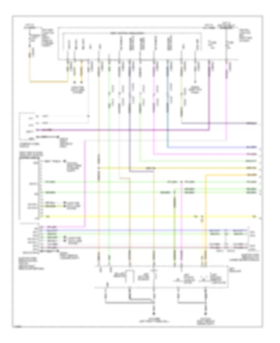
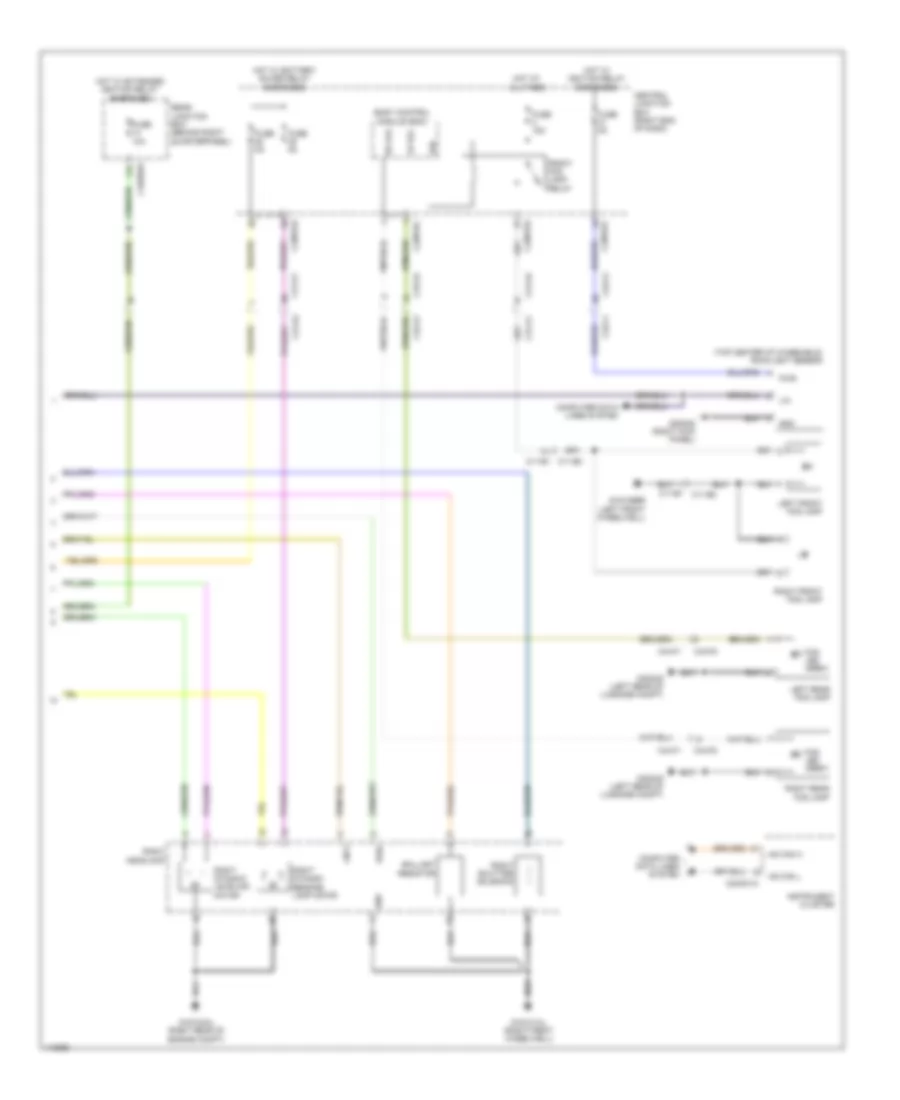
HEADLIGHTS Headlights Wiring Diagram (1 of 2) for Land Rover Range Rover Sport SE 2014 List of elements for Headlights Wiring Diagram (1 of 2) for Land Rover Range Rover Sport SE 2014: 66 (right end of dash) headlamp leveling control module Ballast resistor Battery junction box (right rear of luggage compt) Body control module (bcm) C12-a1 C12-a2 C2bp01a C2bp01b C2bp01c C2bp01d C2bp01e C2bp01f C31-k1 C31-k2 C31-l1 C31-l2 C32-d1 C32-d2 C32-x1 C32-x2 C4bf01f Central junction box (right end of dash) Computer data lines system Dcm r l Dip beam lh Dip beam rh Elec gnd Electric park brake control module (behind right rear quarterpanel) Electric park brake switch (under center console) Fuse 10a Fuse 5a Fusible link 7 40a G1d123al (right rear of engine compt) G1d129br (left front wheelwell) G2d216 (right center of dash) G2d238 (right kick panel) G4d351 (right rear of luggage compt) Gnd Gnd motor r Headlamp pwr lh/rh Hot at all times Hot w/ ignition relay energized Hs can h Hs can l Ign Left dynamic bending lamp motor Left dynamic leveling motor Left headlamp Left shutter solenoid Lin Lin 1 Lin 2 Lin 3 Lin 5 Main beam shutter lh Main beam shutter rh Ms can h Ms can l Pwr Steering wheel module Sw1 Sw2 Sw3 Sw4 Vbatt Vbatt3 Headlights Wiring Diagram (2 of 2) for Land Rover Range Rover Sport SE 2014 List of elements for Headlights Wiring Diagram (2 of 2) for Land Rover Range Rover Sport SE 2014: 55 (top center of windshield) rain/light sensor Ballast resistor Body control module (bcm) C11-b1 C11-b2 C11-b2 c11-b1 C2bp01c C2bp01d C2mc01a C31-a1 C31-a2 C31-k1 C31-k2 C32-a1 C32-a2 C32-f1 C32-f2 C44-f1 C44-f2 C4br02a Central junction box (right end of dash) Computer data lines system Fog led array Front fog lamp relay Fuse 10a Fuse 15a Fuse 5a G1d123al (right rear of engine compt) G1d129br (left front wheelwell) G1d131al (right front wheelwell) G2d238 (right kick panel) G4d349 (left rear of luggage compt) Gnd Hot at all times Hot w/ battery saver relay energized Hot w/ extended ignition relay energized Hot w/ ignition relay energized Hs can h Hs can l Instrument cluster Left front fog lamp Left rear fog lamp Lin Lin 5 Lr fog Lsd Pwr Rear junction box (behind right quarterpanel) Right dynamic bending lamp motor Right dynamic leveling motor Right front fog lamp Right headlamp Right rear fog lamp Right shutter solenoid Rr fog
HORN Horn Wiring Diagram for Land Rover Range Rover Sport SE 2014 List of elements for Horn Wiring Diagram for Land Rover Range Rover Sport SE 2014: 29 Body control module (bcm) C12-a1 c12-a2 C1bb01b C2bp01b C2bp01c C2bp01e C2r115b Central junction box (cjb) (right end of dash) Clock spring (top of steering column) Ctrl horn rly Engine junction box (right rear of engine compt) Fuse 10a Fuse 15a G1d131br G2d216 (right center of dash) Gnd Horn gnd Horn relay Horn sw Horn switch (center of steering wheel) Horns (behind right side of front grille) Hot at all times Left steering wheel switch pack Lin 1 Lin 3 Logic gnd Nca Steering wheel module V batt
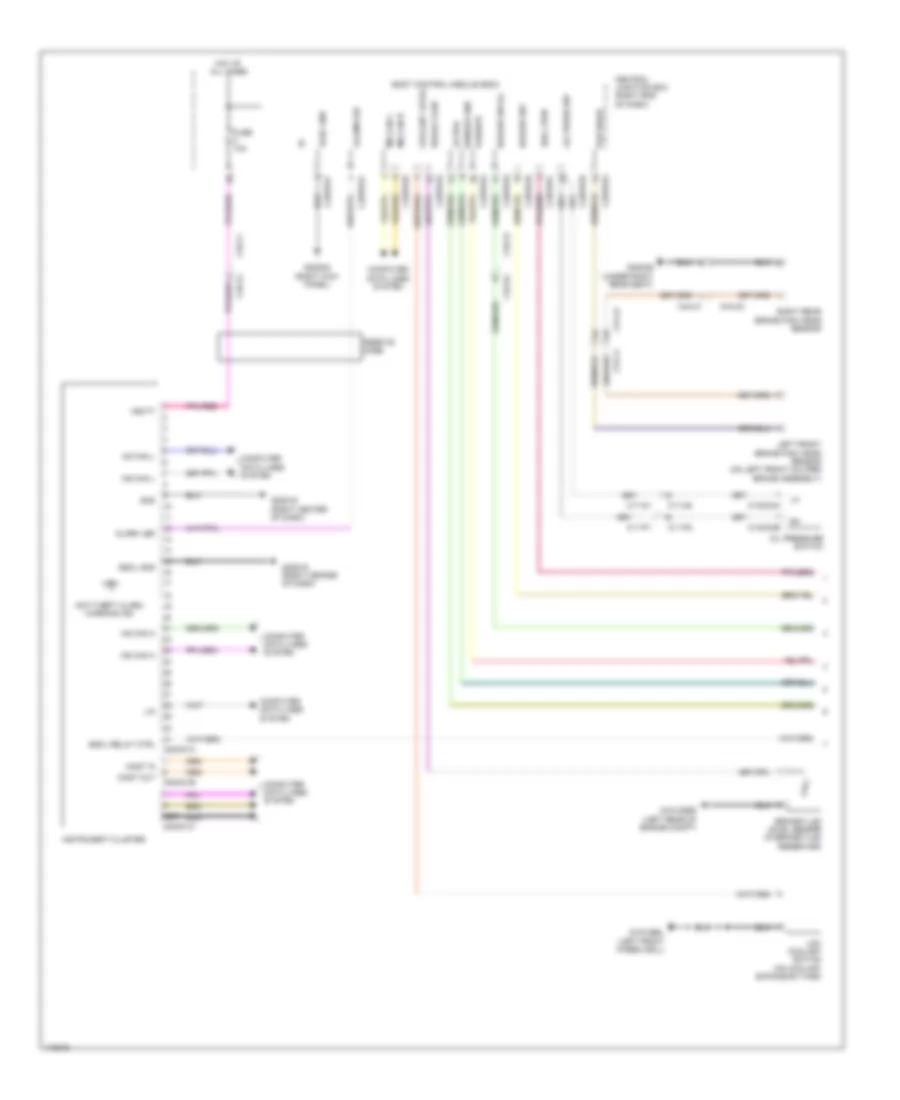
INSTRUMENT CLUSTER Instrument Cluster Wiring Diagram (1 of 2) for Land Rover Range Rover Sport SE 2014 List of elements for Instrument Cluster Wiring Diagram (1 of 2) for Land Rover Range Rover Sport SE 2014: 67 Active Alarm led Anti-theft alarm warning ind Body control module (bcm) Brake fluid Brake fluid level sensor (in brake fluid reservoir) C11-n1 C11-n2 C11-p1 C11-p2 C1mc24a C1mc24b C2bp01a C2bp01b C2bp01c C2bp01e C2bp01f C2bp01g C2bp01h C2mc01a C2mc01b C2mc01c C31-j1 C31-j2 C32-a1 C32-a2 C32-f1 C32-f2 C44-c1 C44-c2 Central junction box (right end of dash) Computer data lines system Coolant level Elec gnd Escl gnd Escl pwr Escl relay ctrl Ferrite core Fuse 10a G1d120bs (left rear of engine compt) G1d129bl (left front wheelwell) G2d216 (right center of dash) G2d238 (right kick panel) G3d389 (under right rear seat) Gnd Hazard sw Hazard sw ill Hot at all times Hs can h Hs can l Instrument cluster Left front brake pad wear sensor (on left front caliper brake assembly) Lin Low coolant switch (on coolant expansion tank) Most in Most out Ms can h Ms can l Nca Oil press sw Oil pressure switch Pad wear Passive Right rear brake pad wear sensor Scr Sensor gnd Vbatt Instrument Cluster Wiring Diagram (2 of 2) for Land Rover Range Rover Sport SE 2014 List of elements for Instrument Cluster Wiring Diagram (2 of 2) for Land Rover Range Rover Sport SE 2014: 25 Active C2me14 C2me14a C4br01a C4mc11c Computer data lines system Escl relay ctrl Fuel tank unit (top right side of fuel tank) Fuse 15a G2d215 (right center of dash) Gnd Hazard ill Hazard sw Hot w/ micro relay 1 energized Hs can h Hs can l Integrated control panel Ms can h Ms can l Passive Pwr Quiescent current control module (behind right rear quarterpanel) Sender rtn Steering column lock module (left side of steering column) Vbatt
INTERIOR LIGHTS Courtesy Lamps Wiring Diagram (1 of 2) for Land Rover Range Rover Sport SE 2014 List of elements for Courtesy Lamps Wiring Diagram (1 of 2) for Land Rover Range Rover Sport SE 2014: 77 (not used) Body control module (bcm) C29-b1 C29-b2 C2bp01a C2bp01b C2bp01c C2bp01d C2bp01f C2bp01g C32-a1 C32-a2 C32-d1 C32-d2 C37-a2 c37-a1 C37-c1 c37-c2 C38-a1 C38-a2 C38-c1 c38-c2 C3a-a2 c3a-a1 C3a-c2 c3a-c1 C3b-a1 c3b-a2 C3b-c1 c3b-c2 C3ln72a C3ln72am C3ln73a C3ln73am C44-ae1 C44-ae2 C49-a1 C49-a2 Central junction box (right end of dash) Computer data lines system Driver door puddle lamp Elec gnd Fl ajar Fr ajar Front interior lamp Front overhead console Fuse 10a Fuse 25a G2d215 (right center of dash) G2d216 (right center of dash) G2d233 (left kick panel) G2d238 (right kick panel) G3d375 (left rear footwell) G3d383c (right front seat cross member) G4d352 (right rear of luggage compt) Glove box illumination lamp Glove box latch switch Hot at all times Hot w/ battery saver relay energized Hsd fet Humidity sensor (top center of windshield) Instrument illumination circuit Int lt sw Left front footwell lamp Left front tread plate illumination Left map lamp Left rear interior lamp Left rear puddle lamp Left vanity mirror Ms can h Ms can l Passenger door puddle lamp Proximity switch module Pwr Right front footwell lamp Right front tread plate illumination Right map lamp Right rear interior lamp Right rear puddle lamp Right vanity mirror Rl ajar Rr ajar Vbatt3 Vbatt4 Courtesy Lamps Wiring Diagram (2 of 2) for Land Rover Range Rover Sport SE 2014 List of elements for Courtesy Lamps Wiring Diagram (2 of 2) for Land Rover Range Rover Sport SE 2014: 60 (right kick panel) g2d238 Ajar switch Approach Battery junction box (right rear of luggage compt) C37-a1 C37-a2 C38-a1 C38-a2 C3a-a1 c3a-a2 C3a-a2 c3a-a1 C3b-a2 c3b-a1 C3ln74a C3ln74am C3ln75 C3ln75m C44-h1 C44-h2 C44-u1 C44-u2 C4bf01f C4bf01g Capw02a Capw02b Cbpw04a Cbpw04b Close global tailgate switch Computer data lines system Driver approach lamp Driver central door locking motor Driver door module Driver side door mirror Fusible link 6 40a Fusible link 7 40a G2d233 (left kick panel) G3d375 (left rear footwell) G3d383c (right front seat cross member) G4d350 (left rear of luggage compt) G4d352 (right rear of luggage compt) Gnd Hot at all times Illum Latch gnd Left rear central door locking motor Left rear door module Left rear tread plate illumination Left tailgate lamp Lin Luggage compartment lamp Mirror gnd Ms can h Ms can l Passenger approach lamp Passenger central door locking motor Passenger door module Passenger side door mirror Right rear central door locking motor Right rear door module Right rear tread plate illumination Right tailgate lamp Vbatt Instrument Illumination Wiring Diagram (1 of 3) for Land Rover Range Rover Sport SE 2014 List of elements for Instrument Illumination Wiring Diagram (1 of 3) for Land Rover Range Rover Sport SE 2014: 83 Aux sw rtn Auxiliary lighting switch Battery junction box (right rear of luggage compt) Body control module (bcm) C22-e1 C22-e2 C2bp01a C2bp01b C2bp01c C2bp01d C2bp01f C2bp01g C2bp01h C2ln71a C2ln71am C2me14 C2me14a C2me14a c2me14 C32-a1 C32-a1 c32-a2 C32-a2 C32-a2 c32-a1 C32-d1 C32-d2 C32-n1 C32-n2 C37-a1 C37-a2 C37-c1 C37-c2 C38-a1 C38-a2 C38-c1 C38-c2 C3a-a1 C3a-a2 C3a-c1 C3a-c2 C3b-a1 C3b-a2 C3b-c1 C3b-c2 C4bf01f Central junction box (right end of dash) Computer data lines system Dimmer sig Driver door pocket ambience lighting Elec gnd Floor console tray illumination Fuse 25a Fuse 5a Fusible link 7 40a G2d215 (right center of dash) G2d216 (right center of dash) G2d233 (left kick panel) G2d238 (right kick panel) G3d375 (left rear footwell) G3d383b (right front seat cross member) G3d383c (right front seat cross member) Gnd Haz sw illum Hot at all times Hot w/ battery saver relay energized Inner left floor console ambience lighting Inner right floor console ambience lighting Integrated control panel Left front footwell lamp Left rear door pocket ambience lighting Lin Ms can h Ms can l Outer left floor console ambience lighting Outer right floor console ambience lighting Passenger door pocket ambience lighting Pwr Red Right front footwell lamp Right rear door pocket ambience lighting Start stop gnd Start-stop switch Sw illum Switch illumination Vbatt3 Instrument Illumination Wiring Diagram (2 of 3) for Land Rover Range Rover Sport SE 2014 List of elements for Instrument Illumination Wiring Diagram (2 of 3) for Land Rover Range Rover Sport SE 2014: 65 (right kick panel) g2d238 12v rear accessory socket Av input panel C29-b1 C29-b2 C32-m2 c32-m1 C32-x1 c32-x2 C37-a1 C37-a2 C37-c1 C37-c2 C38-a1 c38-a2 C38-c1 C38-c2 C3a-a1 c3a-a2 C3a-c1 C3a-c2 C3b-a1 C3b-a2 C3b-c1 C3b-c2 C3me37a C3me37b C3ps186a C3ps186b C3ps186d C3ps51 C44-p1 C44-p2 C4ps51 Computer data lines system Deployable towbar control module (right rear of luggage compt floor) Deployable towbar switch Driver central door locking switch Driver seat memory switchpack Electric parking brake switch (under center console) Fold flat gnd Front cigar lighter Front overhead console G2d233 (left kick panel) G2d238 (right kick panel) G3d362 (under right rear seat) G3d375 (left rear footwell) G3d383b (right front seat cross member) G3d383c (right front seat cross member) G3d389 (under right rear seat) G4d352 (right rear of luggage compt) Gnd Gnd 1 Illum Illum + Illum - Left rear lock/unlock switch Left third row seats switchpack Ms can h Ms can l Passenger central door locking switch Passenger seat memory switchpack Red Right rear lock/unlock switch Right rear seat module Search illum Sw gnd Switch illumination Third row powerfold seats switchpack Instrument Illumination Wiring Diagram (3 of 3) for Land Rover Range Rover Sport SE 2014 List of elements for Instrument Illumination Wiring Diagram (3 of 3) for Land Rover Range Rover Sport SE 2014: 53 (right kick panel) g2d238 C2bp01f C2ls41h C2r115b C37-c1 c37-c2 C38-c1 c38-c2 C3b-c1 c3b-c2 C3bp01c Cbpw04a Cbpw04b Central junction box (right end of dash) Clock spring (top of steering column) Computer data lines system Downshift paddle switch Driver door handle ambience lighting Fuse 10a Fuse 25a G2d216 (right center of dash) G2d233 (left kick panel) G2d238 (right kick panel) G3d375 (left rear footwell) G3d383c (right front seat cross member) Gnd Hot at all times Illum Left rear door handle ambience lighting Left rear door module Left rear window switch Left steering wheel switchpack Lin Logic gnd Logic pwr Ms can h Ms can l Nca Paddle down gnd Paddle down illum Paddle up illum Passenger door handle ambience lighting Passenger door module Passenger door window switch Red Right rear door handle ambience lighting Right rear door module Right rear window switch Right steering wheel switchpack Seats system Status illum Steering wheel module Switch gnd Upshift paddle switch V batt Vbatt
MEMORY SYSTEMS Driver"s Memory Seat Wiring Diagram, 12-Way (1 of 2) for Land Rover Range Rover Sport SE 2014 List of elements for Driver"s Memory Seat Wiring Diagram, 12-Way (1 of 2) for Land Rover Range Rover Sport SE 2014: 68 Bolster def Bolster inf C2bp01f C33-a1 C33-a2 C33-j2 C3a-a1 C3a-c1 C3a-c2 C3ps02a C3ps02d C3ps185a C3ps185b C3ps185c C3ps185d C4br02a Central junction box (right end of dash) Computer data lines system Deflate upper cell Driver backrest tilt motor Driver lumbar pump (driver's seat back) Driver lumbar solenoids Driver seat memory switchpack Driver seat module Driver seat switchpack Extend sens Fuse 15a Fuse 30a G2d233 (left kick panel) G3d375 (left rear footwell) G3d389 (under right rear seat) Gnd Hall sense gnd 2 Headrest sens Height motor sens Hot at all times Hot w/ comfort relay energized Inflate upper cell Interior lights system Left rear seat module Lin Logic feed Logic gnd Lumbar dn Lumbar fwd Lumbar pump Lumbar rwd Lumbar up Memory in Memory out Ms can h Ms can l Power feed 1 Power feed 2 Power gnd 1 Power gnd 2 Rear junction box (behind right quarterpanel) Red Slide motor sens Squab motor incline Squab motor recline Squab motor sens Squab motor sense Status in Status out Switch illum Tilt motor sens Vbatt Driver"s Memory Seat Wiring Diagram, 12-Way (2 of 2) for Land Rover Range Rover Sport SE 2014 List of elements for Driver"s Memory Seat Wiring Diagram, 12-Way (2 of 2) for Land Rover Range Rover Sport SE 2014: 32 C33-ag C33-ah C3ps02b C3ps02c C3ps114b Computer data lines system Cushion extend Cushion retract Driver head restraint motor Driver seat bolster solenoid Driver seat cushion extend motor Driver seat forward/ rearward motor Driver seat module Driver seat tilt motor Drivers seat height motor G3d375 (left rear footwell) Headrest down Headrest up Height motor down Height motor up Lin Master massage solenoid (driver's seat back) Ms can h Ms can l Position sensor Seat backrest recline motor Slide motor forward Slide motor rearward Squab motor incline Squab motor recline Tilt motor down Tilt motor up Driver"s Memory Seat Wiring Diagram, 8-Way (1 of 2) for Land Rover Range Rover Sport SE 2014 List of elements for Driver"s Memory Seat Wiring Diagram, 8-Way (1 of 2) for Land Rover Range Rover Sport SE 2014: 71 (left rear footwell) g3d375 Bolster def Bolster inf C2bp01f C33-a1 C33-a2 C33-ag C33-ah C33-j2 C3a-a1 C3a-c1 C3a-c2 C3ps02e C3ps02f C3ps114b C4br02a Central junction box (right end of dash) Computer data lines system Deflate upper cell Driver lumbar solenoids Driver seat bolster solenoid Driver seat memory switchpack Driver seat module Driver seat switchpack Fuse 15a Fuse 30a G2d233 (left kick panel) G3d375 (left rear footwell) Gnd Height mtr down Height mtr sens Height mtr up Height sense gnd Hot at all times Hot w/ comfort relay energized Inflate Inflate upper cell Interior lights system Lin Logic feed Logic gnd Lumbar dwn Lumbar fwd Lumbar pump Lumbar rwd Lumbar up Massage master solenoid (driver's seat back) Memory in Memory out Ms can h Ms can l Power feed 1 Power gnd 1 Rear junction box (behind right quarterpanel) Slide mtr fwd Slide mtr rwd Slide mtr sens Slide sense gnd Squab mtr incline Squab mtr recline Squab mtr sns Squab sense gnd Status in Status out Switch illum Tilt mtr down Tilt mtr sens Tilt mtr up Tilt sens gnd Upper cell Vbatt Driver"s Memory Seat Wiring Diagram, 8-Way (2 of 2) for Land Rover Range Rover Sport SE 2014 List of elements for Driver"s Memory Seat Wiring Diagram, 8-Way (2 of 2) for Land Rover Range Rover Sport SE 2014: 7 Driver lumbar pump (driver's seat back) Driver seat forward/ rearward motor Driver seat height motor Driver seat tilt motor G3d375 (left rear footwell) Hall effect sensor Recline seat backrest motor Memory Mirrors Wiring Diagram for Land Rover Range Rover Sport SE 2014 List of elements for Memory Mirrors Wiring Diagram for Land Rover Range Rover Sport SE 2014: 64 (left kick panel) g2d233 Ambient air temperature sensor Approach C2bp01c C2bp01f C33-j1 C33-j2 C3a-a1 C3a-a2 C3a-c1 C3a-c2 C4br02a Capw02a Capw02b Cbpw04a Cbpw04b Central junction box (right end of dash) Computer data lines system Driver approach lamp Driver seat memory switchpack Driver seat switchpack Driver side door mirror Driver's door module Engine controls system Fuse 15a Fuse 25a G2d233 (left kick panel) G2d238 (right kick panel) G3d375 (left rear footwell) Gnd Hot at all times Hot w/ comfort relay energized Ign Interior lights system Lin Memory in Memory out Mirror fold in Mirror fold out/y Mirror ground Mirror heating Mirror sensor sply Mirror snsr sply Mirror x Mirror xy Mirrors fold out/y Mirrors system Ms can h Ms can l Navigation system Passenger approach lamp Passenger door module Passenger side door mirror Rear junction box (behind right quarterpanel) Sensor gnd Sensor x Sensor y Side repeater Side repeater lamp Sig Status in Status out Switch illum Vbatt Passenger"s Memory Seat Wiring Diagram, 12-Way (1 of 2) for Land Rover Range Rover Sport SE 2014 List of elements for Passenger"s Memory Seat Wiring Diagram, 12-Way (1 of 2) for Land Rover Range Rover Sport SE 2014: 70 Bolster def Bolster inf C2bp01f C33-c1 C33-c2 C33-k2 C3b-a1 C3b-c1 C3b-c2 C3ps186a C3ps186b C3ps186c C3ps186d C3ps71a C3ps71d C4br02a Central junction box (right end of dash) Computer data lines system Extend sens Fuse 15a Fuse 30a G2d238 (right kick panel) G3d383c (right front seat cross member) G3d389 (under right rear seat) Gnd Hall sense gnd 2 Headrest sens Height motor sens Hot at all times Hot w/ comfort relay energized Interior lights system Lin Logic feed Logic gnd Lumbar dn Lumbar fwd Lumbar pump Lumbar rwd Lumbar up Memory in Memory out Ms can h Ms can l Passenger backrest tilt motor Passenger lumbar pump Passenger lumbar solenoids Passenger seat away switch Passenger seat memory switchpack Passenger seat module Passenger seat switchpack Power feed 1 Power feed 2 Power gnd 1 Power gnd 2 Psa aft Psa fore Psa gnd Rear junction box (behind right quarterpanel) Red Right rear seat module Slide motor sens Squab motor incline Squab motor recline Squab motor sens Squab motor sense Status in Status out Switch illum Tilt motor sens Vbatt Passenger"s Memory Seat Wiring Diagram, 12-Way (2 of 2) for Land Rover Range Rover Sport SE 2014 List of elements for Passenger"s Memory Seat Wiring Diagram, 12-Way (2 of 2) for Land Rover Range Rover Sport SE 2014: 32 C33-aj C33-ak C3ps114d C3ps71b C3ps71c Computer data lines system Cushion extend Cushion retract G3d383c (right front seat cross member) Headrest down Headrest up Height motor down Height motor up Lin Master massage solenoid (left rear seat back) Ms can h Ms can l Passenger head restraint motor Passenger seat backrest recline motor Passenger seat bolster solenoid Passenger seat cushion extension motor Passenger seat forward/ rearward motor Passenger seat module Passenger seat tilt motor Passengers seat height motor Position sensor Slide motor forward Slide motor rearward Squab motor incline Squab motor recline Tilt motor down Tilt motor up Passenger"s Memory Seat Wiring Diagram, 8-Way (1 of 2) for Land Rover Range Rover Sport SE 2014 List of elements for Passenger"s Memory Seat Wiring Diagram, 8-Way (1 of 2) for Land Rover Range Rover Sport SE 2014: 68 (right front seat cross member) g3d383c Bolster def Bolster inf C33-aj C33-ak C33-c1 C33-c2 C33-k2 C3b-a1 C3b-c1 C3b-c2 C3ps114d C3ps71e C3ps71f C4br02a Computer data lines system Deflate Fuse 15a Fuse 30a G2d238 (right kick panel) G3d383c (right front seat cross member) Gnd Headrest up Height mtr down Height mtr sens Height mtr up Height sense gnd Hot at all times Hot w/ comfort relay energized Inflate Interior lights system Lin Logic feed Logic gnd Lumbar dwn Lumbar fwd Lumbar pump Lumbar rwd Lumbar up Massage master solenoid Memory in Memory out Ms can h Ms can l Passenger lumbar solenoids Passenger seat bolster solenoid Passenger seat memory switchpack Passenger seat module Passenger seat switchpack Power feed 1 Power gnd 1 Rear junction box (behind right quarterpanel) Red Slide mtr fwd Slide mtr rwd Slide mtr sens Slide sense gnd Squab mtr incline Squab mtr recline Squab mtr sns Squab sense gnd Status in Status out Switch illum Tilt mtr down Tilt mtr sens Tilt mtr up Vbatt Passenger"s Memory Seat Wiring Diagram, 8-Way (2 of 2) for Land Rover Range Rover Sport SE 2014 List of elements for Passenger"s Memory Seat Wiring Diagram, 8-Way (2 of 2) for Land Rover Range Rover Sport SE 2014: 7 G3d383c (right front seat cross member) Hall effect sensor Passenger lumbar pump Passenger recline seat backrest motor Passenger seat forward/ rearward motor Passenger seat height motor Passenger seat tilt motor Steering Column Memory Wiring Diagram for Land Rover Range Rover Sport SE 2014 List of elements for Steering Column Memory Wiring Diagram for Land Rover Range Rover Sport SE 2014: 67 Auto Battery junction box (right rear of luggage compt) Body control module C12-a1 C12-a2 C2bp01a C2bp01c C2bp01d C2bp01e C2bp01f C2bp01h C2pp03a C2pp03b C32-d1 C32-d2 C33-j1 C33-j2 C3a-a1 C3a-a2 C3a-c1 C3a-c2 C3bp01c C4bf01f C4br02a Central junction box (right end of dash) Col adj easy entry Col adj gnd Col adj sw Col motor extend Column Column motor down Column motor retract Column tilt/up Computer data lines system Down Driver seat memory switchpack Driver seat switchpack Fuse 15a Fusible link 7 40a G2d233 (left kick panel) G2d238 (right kick panel) G3d375 (left rear footwell) Gnd Hot at all times Hot w/ comfort relay energized Hs can h Hs can l I col adj hall count telescope I col adj hall count tilt Interior lights system Isolator switch Lin Memory in Memory out Out Rear junction box (behind right quarterpanel) Sensor telescope Status in Status out Steering column adjust motor Steering column adjustment switchpack Steering column assembly Switch illum Tilt motor Tilt sensor Vbatt Vbatt3
NAVIGATION Blind Spot Monitoring Wiring Diagram for Land Rover Range Rover Sport SE 2014 List of elements for Blind Spot Monitoring Wiring Diagram for Land Rover Range Rover Sport SE 2014: 35 C3a-a1 C3a-a2 C3b-a1 C3b-a2 C4br02a Capw02a Capw02b gnd mirror Cbpw04a Cbpw04b gnd passenger's door module Computer data lines system Driver side door mirror Driver's door module Fuse 10a G2d233 (left kick panel) G2d238 (right kick panel) G4d350 (left rear of luggage compt) Gnd Hot w/ extended ignition relay energized Left blind spot monitoring module (behind left end of rear bumper) Mirr gnd Mirror Ms can h Ms can l Passenger side door mirror Private can h Private can l Rear junction box (behind right quarterpanel) Right blind spot monitoring module (behind right end of rear bumper) Status led System System status System status led Vbatt Warning alert Warning alert led Multi Camera Wiring Diagram for Land Rover Range Rover Sport SE 2014 List of elements for Multi Camera Wiring Diagram for Land Rover Range Rover Sport SE 2014: 80 (right center of tailgate) 7-seat C11-d1 C11-d2 C11-e1 C11-e2 C2mc02a C2mc02c C31-g1 C31-g2 C31-h1 C31-h2 C32-h2 c32-h1 C3a-am1 C3a-am2 C3b-am1 C3b-am2 C3mp22a C3mp22b C3mp22c C3mp22d C3mp22e C3mp22f C3mp22g C43-c1 C43-c2 C44-q1 C44-q2 C4br02a Camera shield Camera video Computer data lines system Fuse 10a G2d284 (left center of dash) G4d347 (left "c" pillar) Gnd Gnd 1 Hot w/ extended ignition relay energized Image processing module (left "c" pillar) Left front proximity camera (behind left end of front bumper) Left mirror proximity camera (left front outside rearview mirror assembly) Lh front lin Lh front lvds pos Lh front lvds scr Lh front v pos Lh mirror lin Lh mirror lvds pos Lh mirror lvds scr Lh mirror v pos Lin Lvds + Lvds - Lvds pos Lvds scr gnd Ms can h Ms can l Nca Power Rear junction box (behind right quarterpanel) Rear lin Rear lvds pos Rear lvds scr Rear v pos Rearview camera Rh front lin Rh front lvds pos Rh front lvds scr Rh front v pos Rh mirror lin Rh mirror lvds scr Rh mirror v pos Right front proximity camera (behind right end of front bumper) Right mirror proximity camera (right front outside rearview mirror assembly) Scr Touch screen V pos Video + Video - W/ swc W/o swc Navigation Wiring Diagram, 19-Speaker System (1 of 6) for Land Rover Range Rover Sport SE 2014 List of elements for Navigation Wiring Diagram, 19-Speaker System (1 of 6) for Land Rover Range Rover Sport SE 2014: 60 (under driver's seat) Audio amplifier module C29-a1 C29-a2 C37-a1 C37-a2 C38-a1 C38-a2 C38-c1 c38-c2 C3me22a C3me22b C3me22c C3me22d C3me22e C3me22h C4br01a C4br02a Computer data lines system Data 1 Data 2 Fr cntr high pos Fr cntr mid pos Fuse 10a Fusible link 40a G3d161 (under center console) Gnd Gnd shield Hot at all times Hot w/ micro relay 1 energized Left rear door bass speaker Lf high pos Lf low pos Lf mid pos Lh surr pos Lr low pos Lr mid pos Most in Most out Nca Power Pwr Quiescent current control module (behind right rear quarterpanel) Rbd Rbd gnd Rear junction box (behind right quarterpanel) Red Rf high pos Rf low pos Rf mid pos Right rear door bass speaker Right rear door mid range speaker Right rear door tweeter Rr low pos Rr mid pos Scr Shield Sw 1 pos Sw 2 pos Vbatt Wireless headphones Navigation Wiring Diagram, 19-Speaker System (2 of 6) for Land Rover Range Rover Sport SE 2014 List of elements for Navigation Wiring Diagram, 19-Speaker System (2 of 6) for Land Rover Range Rover Sport SE 2014: 24 C22-d1 C22-d2 C32-n1 C32-n2 C37-a1 c37-a2 C37-c1 c37-c2 C3b-a1 C3b-a2 C3b-c1 C3b-c2 C49-c1 C49-c2 C49-d1 C49-d2 Front center mid range speaker Left luggage compartment tweeter Left mid range luggage compartment speaker Left rear door mid range speaker Left rear door tweeter Right front door bass speaker Right front door mid range speaker Right front tweeter Right luggage compartment tweeter Right mid range luggage compartment speaker Navigation Wiring Diagram, 19-Speaker System (3 of 6) for Land Rover Range Rover Sport SE 2014 List of elements for Navigation Wiring Diagram, 19-Speaker System (3 of 6) for Land Rover Range Rover Sport SE 2014: 22 C22-d1 C22-d2 C2me14 C2me14a C32-n1 C32-n2 C3a-a1 C3a-a1 c3a-a2 C3a-a2 C3a-c1 c3a-c2 Center front tweeter Computer data lines system G2d215 (right center of dash) Gnd Integrated control panel Left front door bass speaker Left front door mid range speaker Left front tweeter Ms can h Ms can l Subwoofer speaker Vbatt Navigation Wiring Diagram, 19-Speaker System (4 of 6) for Land Rover Range Rover Sport SE 2014 List of elements for Navigation Wiring Diagram, 19-Speaker System (4 of 6) for Land Rover Range Rover Sport SE 2014: 71 (pins: 1 to 13 not used) (pins: 16 to 20 not used) (pins: 24 to 28 not used) C23-a1 C23-a2 C2mc01b C2mc01c C2mc02a C2mc02b C2mc02c C2mc02d C2mc02e C2mc02f C2mc02i C2mc02j C2mm25a C2mm25b C2mm25d C2mm25e C2mm25f C32-f1 C32-f2 C32-n1 C32-n2 C4br01a Cam shield Cam video Computer data lines system Cvbs gnd Cvbs sig Cvbs2 gnd Cvbs2 sig Diag rtn Diag send Fuse 10a Fuse 15a G2d284 (left center of dash) Gnd Gnd 1 Gnd 2 Gnd shield Hot w/ micro relay 1 energized Iam cvbs gnd Iam cvbs in Instrument cluster Lvds pos Lvds scr Most in Most out Ms can h Ms can h (co) Ms can l Ms can l (co) Navigation system Nca Quiescent current control module (behind right rear quarterpanel) Rear seat entertainment circuit Red Scr Sply 1 Sply 2 Sw audio switch Telephone interface module (if equipped) Touch screen Usb d+ Usb d- Usb gnd Usb v+ Vbatt W/ telephone interface W/o telephone interface Navigation Wiring Diagram, 19-Speaker System (5 of 6) for Land Rover Range Rover Sport SE 2014 List of elements for Navigation Wiring Diagram, 19-Speaker System (5 of 6) for Land Rover Range Rover Sport SE 2014: 54 Antenna amplifier Av input panel Band 3 ant gnd Band 3 ant gnd band l ant Band l ant C23-c1 C23-c2 C29-b1 C29-b2 C32-d1 C32-d2 C3me37a C3me37b C44-y1a C44-y2a C4me24a C4me24b C4me24c C4me41a C4me41b C4me41c Computer data lines system Diag + Diag - Digital radio control module Front overhead console G3d172 (left rear of luggage compt) G4d480bl (center rear of roof) Gnd Ill + Ill - Interior lights system Lh + Lh - Mic+ Mic- Most in Most out Nca Red Rh + Rh - Sat rf gnd Sat rf in Satellite radio control module (behind left rear quarterpanel) Scn Sdars antenna Shield Sig Usb data pos Usb gnd Usb pos Usb scr Vbatt Navigation Wiring Diagram, 19-Speaker System (6 of 6) for Land Rover Range Rover Sport SE 2014 List of elements for Navigation Wiring Diagram, 19-Speaker System (6 of 6) for Land Rover Range Rover Sport SE 2014: 98 Am-fm scn Am-fm sig Am/fm antenna amplifier (top left side of tailgate) Ant amp Audio ladder Audio ladder rtn Aux1 l + Aux1 l r- Aux1 r + C23-a1 C23-a2 C2me03a C2me03d C2me03e C2me03f C2me03g C2me03h C2r115b C32-aa1 C32-aa2 C32-c1 C32-c2 C32-ga1 C32-ga2 C32-v1 C32-v2 C44-w1 C44-w2 C44-x1 C44-x2 C44-z1 C44-z2 C4me192a C4me192b C9me115 C9me115a C9me46c C9mn03a Clock spring (top of steering column) Computer data lines system Cvbs video out Cvbs video scn Down/ back switch Ferrite core Fm antenna amplifier (top right side of tailgate) Fm2 Fm2 scn c2me03c Forward/ up switch G2d216 (right center of dash) G2d284 (left center of dash) G4d480bl (center rear of roof) G4d480br (center rear of roof) Global positioning system antenna Gnd Gps in gnd Gps in sig Gps out gnd Gps out sig Gps scrn Gps sig Gps signal splitter Hs can h Hs can l Ice 1 Ice 2 Integrated audio module Left steering wheel switchpack Logic gnd Lvds data out+ Lvds data out- Mic 1 pos Mode switch Most in Most out Nca Phone end switch Phone send switch Pwr Pwr gnd Radio phone switch Red Scn Scr Scr gnd Seek down switch Seek up switch Sig Steering wheel module (left side of steering column) Usb 5v Usb data pos Usb gnd Usb scr Vbatt Voice switch Volume + switch Volume - switch W/ gps signal splitter W/o gps signal splitter Navigation Wiring Diagram, 23-Speaker System (1 of 7) for Land Rover Range Rover Sport SE 2014 List of elements for Navigation Wiring Diagram, 23-Speaker System (1 of 7) for Land Rover Range Rover Sport SE 2014: 59 Audio amplifier module (under driver's seat) Battery junction box (right rear of luggage compt) C29-a1 C29-a2 C29-b1 C29-b2 C3me22b C3me22c C3me22f C3me22g C3me22j C49-a1 C49-a2 C4bf01h C4br01a Computer Data 1 Data 2 Data lines Fuse 10a Fusible link 80a G3d161 (under center console) Gnd Hot at all times Hot w/ micro relay 1 energized Left front headliner speaker Left front microphone Left rear headliner speaker Lf headlining mic pos Lf headlining mic scr Lf headlining pos Lr headlining mic pos Lr headlining mic scr Lr headlining pos Lr high pos Most in Most out Nca Pos Power Quiescent current control module (behind right rear quarterpanel) Rbd Red Rf headlining mic pos Rf headlining mic scr Rf headlining pos Right front headliner speaker Right front microphone Right rear headliner speaker Rr headlining mic pos Rr headlining mic scr Rr headlining pos Rr high pos Scr Shield System Vbatt 1 Vbatt 2 Wireless headphones Navigation Wiring Diagram, 23-Speaker System (2 of 7) for Land Rover Range Rover Sport SE 2014 List of elements for Navigation Wiring Diagram, 23-Speaker System (2 of 7) for Land Rover Range Rover Sport SE 2014: 28 C22-d2 c22-d1 C32-n1 C32-n2 C37-a1 C37-a2 C37-c1 C37-c2 C38-a1 C38-a2 C38-c1 C38-c2 C3a-a1 C3a-a2 C49-a2 c49-a1 C49-c1 C49-c2 C49-d1 C49-d2 Front center mid range speaker Left front tweeter Left mid range luggage compartment speaker Left rear door tweeter Left rear microphone Pos Right luggage compartment tweeter Right mid range luggage compartment speaker Right rear door tweeter Right rear microphone Navigation Wiring Diagram, 23-Speaker System (3 of 7) for Land Rover Range Rover Sport SE 2014 List of elements for Navigation Wiring Diagram, 23-Speaker System (3 of 7) for Land Rover Range Rover Sport SE 2014: 20 C22-d1 C22-d2 C32-n1 C32-n2 C3a-a1 C3a-a2 C3a-c1 C3a-c2 C3b-a1 C3b-a2 C3b-c1 C3b-c2 Front center tweeter Left front door bass speaker Left front door mid range speaker Left luggage compartment tweeter Right front door bass speaker Right front door mid range speaker Right front tweeter Subwoofer speaker Navigation Wiring Diagram, 23-Speaker System (4 of 7) for Land Rover Range Rover Sport SE 2014 List of elements for Navigation Wiring Diagram, 23-Speaker System (4 of 7) for Land Rover Range Rover Sport SE 2014: 40 Audio amplifier module (under driver's seat) C2me14 C2me14a C37-a1 C37-a2 C37-c1 C37-c2 C38-a1 C38-a2 C38-c1 C38-c2 C3me22d C3me22e Centre high pos Centre mid pos Computer data lines system G2d215 (right center of dash) Gnd Integrated control panel Left rear door bass speaker Left rear door mid range speaker Lf high pos Lf low pos Lf mid pos Lh surround pos Lr low pos Lr mid pos Ms can h Ms can l Rf high pos Rf low pos Rf mid pos Rh surround pos Right rear door bass speaker Right rear door mid range speaker Rr low pos Rr mid pos Sw 1 pos Sw 2 pos Vbatt Navigation Wiring Diagram, 23-Speaker System (5 of 7) for Land Rover Range Rover Sport SE 2014 List of elements for Navigation Wiring Diagram, 23-Speaker System (5 of 7) for Land Rover Range Rover Sport SE 2014: 71 (pins: 1 to 13 not used) (pins: 16 to 20 not used) (pins: 24 to 28 not used) C23-a1 C23-a2 C2mc01b C2mc01c C2mc02a C2mc02b C2mc02c C2mc02d C2mc02e C2mc02f C2mc02i C2mc02j C2mm25a C2mm25b C2mm25d C2mm25e C2mm25f C32-f1 C32-f2 C32-n1 C32-n2 C4br01a Cam shield Cam video Computer data lines system Cvbs gnd Cvbs sig Cvbs2 gnd Cvbs2 sig Diag rtn Diag send Fuse 10a Fuse 15a G2d284 (left center of dash) Gnd Gnd 1 Gnd 2 Gnd shield Hot w/ micro relay 1 energized Iam cvbs gnd Iam cvbs in Instrument cluster Lvds pos Lvds scr Most in Most out Ms can h Ms can h (co) Ms can l Ms can l (co) Navigation system Nca Quiescent current control module (behind right rear quarterpanel) Rear seat entertainment circuit Red Scr Sply 1 Sply 2 Sw audio switch Telephone interface module (if equipped) Touch screen Usb d+ Usb d- Usb gnd Usb v+ Vbatt W/ telephone interface W/o telephone interface Navigation Wiring Diagram, 23-Speaker System (6 of 7) for Land Rover Range Rover Sport SE 2014 List of elements for Navigation Wiring Diagram, 23-Speaker System (6 of 7) for Land Rover Range Rover Sport SE 2014: 54 Antenna amplifier Av input panel Band 3 ant gnd Band 3 ant gnd band l ant Band l ant C23-c1 C23-c2 C29-b1 C29-b2 C32-d1 C32-d2 C3me37a C3me37b C44-y1a C44-y2a C4me24a C4me24b C4me24c C4me41a C4me41b C4me41c Computer data lines system Diag + Diag - Digital radio control module Front overhead console G3d172 (left rear of luggage compt) G4d480bl (center rear of roof) Gnd Ill + Ill - Interior lights system Lh + Lh - Mic+ Mic- Most in Most out Nca Red Rh + Rh - Sat rf gnd Sat rf in Satellite radio control module (behind left rear quarterpanel) Scn Sdars antenna Shield Sig Usb data pos Usb gnd Usb pos Usb scr Vbatt Navigation Wiring Diagram, 23-Speaker System (7 of 7) for Land Rover Range Rover Sport SE 2014 List of elements for Navigation Wiring Diagram, 23-Speaker System (7 of 7) for Land Rover Range Rover Sport SE 2014: 98 Am-fm scn Am-fm sig Am/fm antenna amplifier (top left side of tailgate) Ant amp Audio ladder Audio ladder rtn Aux1 l + Aux1 l r- Aux1 r + C23-a1 C23-a2 C2me03a C2me03d C2me03e C2me03f C2me03g C2me03h C2r115b C32-aa1 C32-aa2 C32-c1 C32-c2 C32-ga1 C32-ga2 C32-v1 C32-v2 C44-w1 C44-w2 C44-x1 C44-x2 C44-z1 C44-z2 C4me192a C4me192b C9me115 C9me115a C9me46c C9mn03a Clock spring (top of steering column) Computer data lines system Cvbs video out Cvbs video scn Down/ back switch Ferrite core Fm antenna amplifier (top right side of tailgate) Fm2 Fm2 scn c2me03c Forward/ up switch G2d216 (right center of dash) G2d284 (left center of dash) G4d480bl (center rear of roof) G4d480br (center rear of roof) Global positioning system antenna Gnd Gps in gnd Gps in sig Gps out gnd Gps out sig Gps scrn Gps sig Gps signal splitter Hs can h Hs can l Ice 1 Ice 2 Integrated audio module Left steering wheel switchpack Logic gnd Lvds data out+ Lvds data out- Mic 1 pos Mode switch Most in Most out Nca Phone end switch Phone send switch Pwr Pwr gnd Radio phone switch Red Scn Scr Scr gnd Seek down switch Seek up switch Sig Steering wheel module (left side of steering column) Usb 5v Usb data pos Usb gnd Usb scr Vbatt Voice switch Volume + switch Volume - switch W/ gps signal splitter W/o gps signal splitter Navigation Wiring Diagram, 8-Speaker System (1 of 5) for Land Rover Range Rover Sport SE 2014 List of elements for Navigation Wiring Diagram, 8-Speaker System (1 of 5) for Land Rover Range Rover Sport SE 2014: 56 Audio amplifier module (under driver's seat) C29-a1 C29-a2 C37-a1 C37-a1 c37-a2 C37-a2 C37-c1 c37-c2 C38-a1 C38-a2 C38-c1 c38-c2 C3me22a C3me22b C3me22c C3me22d C3me22h C4br01a C4br02a Computer data lines system Data 1 Data 2 Fuse 10a Fusible link 40a G3d161 (under center console) Gnd Hot at all times Hot w/ micro re1 relay 1 energized Left rear door bass speaker Left rear door tweeter Lf high pos Lf low pos Lr low pos Lr mid pos Most in Most out Nca Power Quiescent current control module (behind right rear quarterpanel) Rbd Rbd gnd Rear junction box (behind right quarterpanel) Red Rf high pos Rf low pos Right rear door bass speaker Right rear door tweeter Rr low pos Rr mid pos Scr Shield Vbatt Whitefire data 1 Whitefire data 2 Whitefire gnd Whitefire pwr Whitefire shield Wireless headphone Navigation Wiring Diagram, 8-Speaker System (2 of 5) for Land Rover Range Rover Sport SE 2014 List of elements for Navigation Wiring Diagram, 8-Speaker System (2 of 5) for Land Rover Range Rover Sport SE 2014: 29 (left side of steering column) steering wheel module Audio ladder Audio ladder rtn C2r115b C3a-a1 C3a-a2 C3b-a1 C3b-a2 Clock spring (top of steering column) Computer data lines system Down/back switch Forward/up switch G2d216 (right center of dash) Gnd Hs can h Hs can l Ice 1 Ice 2 Left front door bass speaker Left front tweeter Left steering wheel switchpack Logic gnd Nca Radio phone switch Right front door bass speaker Right front tweeter Voice switch Volume + switch Volume - switch Navigation Wiring Diagram, 8-Speaker System (3 of 5) for Land Rover Range Rover Sport SE 2014 List of elements for Navigation Wiring Diagram, 8-Speaker System (3 of 5) for Land Rover Range Rover Sport SE 2014: 68 Am/fm antenna amplifier (top left side of tailgate) C29-b1 C29-b2 C2mc01b C2mc01c C2mc02a C2mc02b C2mc02c C2mc02d C2mc02e C2mc02f C2mc02i C2mc02j C2me14 C2me14a C2me14b C32-d1 C32-d2 C32-f1 c32-f2 C32-n1 C32-n2 C4br01a C9me115 C9me115a Camera shield Camera video Computer data lines system Ferrite core Front overhead console Fuse 10a Fuse 15a G2d215 (right center of dash) G2d284 (left center of dash) G4d480bl (center rear of roof) Gnd Gnd 1 Gnd 2 Hot w/ micro re1 relay 1 energized Iam cvbs gnd Iam cvbs in Instrument cluster Integrated control panel Lvds pos Lvds scr Mic+ Mic- Most in Most out Ms can h Ms can l Navigation system Nca Pwr Quiescent current control module (qccm) (behind right rear quarterpanel) Rear seat entertainment circuit Red Rse cvbs gnd Rse cvbs sig Scn Scr Sig Sply 1 Sply 2 Sw audio switch Touch screen Vbatt W/ telephone interface module W/o telephone interface module Navigation Wiring Diagram, 8-Speaker System (4 of 5) for Land Rover Range Rover Sport SE 2014 List of elements for Navigation Wiring Diagram, 8-Speaker System (4 of 5) for Land Rover Range Rover Sport SE 2014: 47 (if equipped) telephone interface module (or red) Av input panel C23-a1 C23-a2 C23-c1 C23-c2 C2mm25a C2mm25b C2mm25d C2mm25e C2mm25f C32-m1 C32-m2 C3me37a C3me37b Computer data lines system Diag + Diag - Diag rtn Diag send G2d284 (left center of dash) G3d362 (under right rear seat) Global positioning system antenna Gnd Gnd b- Illum + Illum - Interior lights system Lh pos Ms can h Ms can l Nca Red Rh pos Scr Scrn Shield Sig Usb data pos Usb gnd Usb pos Usb scr Vbatt W/ telephone interface module W/o gps signal splitter W/o telephone interface module Navigation Wiring Diagram, 8-Speaker System (5 of 5) for Land Rover Range Rover Sport SE 2014 List of elements for Navigation Wiring Diagram, 8-Speaker System (5 of 5) for Land Rover Range Rover Sport SE 2014: 92 (if equipped) gps signal splitter (or red) Am-fm Am-fm scn Ant amp Antenna amplifier Aux1 l + Aux1 l r- Aux1 r + Band 3 ant gnd Band l ant band l ant C23-a1 C23-a2 C2me03a C2me03d C2me03e C2me03f C2me03g C2me03h C32-aa1 C32-aa2 C32-c1 C32-c2 C32-ga1 C32-ga2 C32-v1 C32-v2 C44-w1 C44-w2 C44-x1 C44-x2 C44-y1a C44-y2a C44-z1 C44-z2 C4me192a C4me192b C4me24a C4me24b C4me24c C4me41a C4me41b C4me41c C9me116b C9me46b C9me46c Computer data lines system Cvbs video out Cvbs video scn Digital radio control module Ferrite core Fm antenna amplifier (top right side of tailgate) Fm2 Fm2 scn c2me03c G2d284 (left center of dash) G3d172 (left rear of luggage compt) G4d480bl (center rear of roof) G4d480br (center rear of roof) Global positioning system antenna Gnd Gnd band 3 ant Gps in gnd Gps in sig Gps out gnd Gps out sig Gps scrn Gps sig Integrated audio module Lvds data out+ Lvds data out- Mic 1 pos Most in Most out Nca Pwr gnd Red Sat rf gnd Sat rf in Satellite radio control module (behind left rear quarterpanel) Scn Scr Scr gnd Scrn Sdars antenna Sig Usb 5v Usb data pos Usb gnd Usb scr Vbatt W/ gps signal splitter W/o gps signal splitter Parking Assistant Wiring Diagram, with SWC for Land Rover Range Rover Sport SE 2014 List of elements for Parking Assistant Wiring Diagram, with SWC for Land Rover Range Rover Sport SE 2014: 67 (behind left end of rear bumper) (behind left rear quarterpanel) g3d347 (behind left side of rear bumper) left rear inner parking aid sensor (behind left side of rear bumper) left rear outer parking aid sensor (behind right end of rear bumper) right rear parking aid control slot detect sensor (behind right side of rear bumper) right rear inner parking aid sensor (behind right side of rear bumper) right rear outer parking aid sensor (left center of dash) g2d284 C11-b1 c11-b2 C11-b2 c11-b1 C2bp01c C31-e1 c31-e2 C31-e2 c31-e1 C31-l1 c31-l2 C32-n1 C32-n2 C3mp01a C3mp01b C43-b1 C43-bb2 C44-f1 C44-f2 C4br02a Central junction box (right end of dash) Computer data Computer data lines system Fuse 10a Fuse 5a Gnd Gnd front Gnd rear Hot at all times Hot w/ extended ignition relay energized Hs can h Hs can l Ign Ign front Ign rear Led park assist Left front inner parking aid sensor (behind left side of front bumper) Left front outer parking aid sensor (behind left side of front bumper) Left front parking aid control slot detect sensor (behind left end of front bumper) Left rear parking aid control slot detect sensor Left touch screen switchpack Lines system Parking aid control module (behind left quarterpanel) Pdc led Pdc sw Rear junction box (behind right quarterpanel) Right front inner parking aid sensor (behind right side of front bumper) Right front outer parking aid sensor (behind right side of front bumper) Right front parking aid control slot detect sensor (behind right end of front bumper) Right touch screen switchpack Sig Sig fl inner Sig fl outer Sig fl slot Sig fr inner Sig fr outer Sig fr slot Sig rl inner Sig rl outer Sig rl slot Sig rr inner Sig rr outer Sig rr slot Sw park assist Parking Assistant Wiring Diagram, without SWC for Land Rover Range Rover Sport SE 2014 List of elements for Parking Assistant Wiring Diagram, without SWC for Land Rover Range Rover Sport SE 2014: 67 (behind left end of rear bumper) left rear parking aid control slot detect sensor (behind left rear quarterpanel) g3d347 (behind left side of rear bumper) left rear inner parking aid sensor (behind left side of rear bumper) left rear outer parking aid sensor (behind right end of rear bumper) right rear parking aid control slot detect sensor (behind right side of rear bumper) right rear inner parking aid sensor (behind right side of rear bumper) right rear outer parking aid sensor (left center of dash) g2d284 (not used) 7-seat C11-b1 c11-b2 C2bp01c C31-e1 c31-e2 C31-l1 c31-l2 C32-n1 C32-n2 C3mp01a C3mp01b C43-b1 C43-b1 c43-ba2 C43-ba2 C44-f1 C44-f2 C4br02a Central junction box (right end of dash) Computer data Computer data lines system Fuse 10a Fuse 5a Gnd Gnd front Gnd rear Hot at all times Hot w/ extended ignition relay energized Hs can h Hs can l Ign Ign front Ign rear Led park assist Left front inner parking aid sensor (behind left side of front bumper) Left front outer parking aid sensor (behind left side of front bumper) Left front parking aid control slot detect sensor (behind left end of front bumper) Left touch screen switchpack Lines system Parking aid control module (behind left quarterpanel) Pdc led Pdc sw Rear junction box (behind right quarterpanel) Right front inner parking aid sensor (behind right side of front bumper) Right front outer parking aid sensor (behind right side of front bumper) Right front parking aid control slot detect sensor (behind right end of front bumper) Right touch screen switchpack Sig Sig fl inner Sig fl outer Sig fl slot Sig fr inner Sig fr outer Sig fr slot Sig rl inner Sig rl outer Sig rl slot Sig rr inner Sig rr outer Sig rr slot Sw park assist Rear View Camera Wiring Diagram, with SWC for Land Rover Range Rover Sport SE 2014 List of elements for Rear View Camera Wiring Diagram, with SWC for Land Rover Range Rover Sport SE 2014: 23 (right center of tailgate) rear view camera C2mc02c C32-fa1 C32-fa2 C43-b1 C43-bb2 C43-d1 C43-db2 C4br02a Can-h Can-l Cmr shield Cmr video Computer data lines system Fuse 14 10a G4d347 (left "c" pillar) Gnd Hot w/ extended ignition relay energized Nca Pwr Rear junction box (behind right quarterpanel) Red Touch screen display Rear View Camera Wiring Diagram, without SWC for Land Rover Range Rover Sport SE 2014 List of elements for Rear View Camera Wiring Diagram, without SWC for Land Rover Range Rover Sport SE 2014: 31 (center of roof) g4d480 7-seat C2mc02a C2mc02c C32-fa1 C32-fa2 C43-ba1 C43-ba2 C43-d1 C43-da2 C44-k1 C44-k2 C44-r1 C44-r2 C4br02a Cmr shield Cmr shield cmr video gnd Cmr video Computer data lines system Ferrite core Fuse 10a G2d284 (left center of dash) Gnd Hot w/ extended ignition relay energized Nca Pwr Rear junction box (behind right quarterpanel) Rear view camera (right center of tailgate) Red Rf filter Touch screen Telematics Wiring Diagram for Land Rover Range Rover Sport SE 2014 List of elements for Telematics Wiring Diagram for Land Rover Range Rover Sport SE 2014: 87 +5v dc 3.0l 5.0l sc Batt Bcall activated led Bcall btn backlight Body control module (bcm) Btn diagnostic o/p Btn input common C11-m1 C11-m2 C12-a1 C12-a2 C1e120a C1e121a C29-b1 C29-b2 C2bp01a C31-l1 C31-l2 C32-d1 C32-d2 C32-g1 C32-g2 C32-j1 C32-j2 C33-y1 C33-y2 C39-a1 C39-a2 C3r114b C4br02a C4me192a C4me192c C4mt01a C4mt01b C4mt01c C4mt01d C9ln28 C9ln28a Central junction box (right end of dash) Computer data lines system Crash sig Data + Data - Diagnostic 1 Diagnostic 2 Ecall + bcall btn Ecall activated led Ecall btn backlight Engine control module (ecm) (left rear of engine compt) Ens Front overhead console Fuse 15a G2d216 (right center of dash) Global positioning antenna system Gnd Gnd screen Gps scrn Gps sig Gps signal splitter Gsm antenna Hot at all times Hs can-h Hs can-l Integrated audio module J-f-crash Led o/p common Mbm ant sig Mic + Mic - Mic 1 pos Ms can-h Ms can-l Nca Rear junction box (behind right quarterpanel) Red Restraints control module (under front of center console) Scr Sig Speaker + Speaker - Telematics module (under left side of dash) Telematics speaker Usb sim wi-fi module (under left side of dash) W/ gps signal splitter W/o gps signal splitter Vehicle Proximity Notification Wiring Diagram for Land Rover Range Rover Sport SE 2014 List of elements for Vehicle Proximity Notification Wiring Diagram for Land Rover Range Rover Sport SE 2014: 22 C3a-a1 c3a-a2 C3b-a2 c3b-a1 C4br02a Computer data lines system Driver side door mirror Fuse 10a G3d347 (behind left rear quarterpanel) General proximity sensor module (left "c" pillar) Gnd Gnd left Gnd right Hot w/ extended ignition relay energized Hs can h Hs can l Ign Ign left Ign right Passenger side door mirror Rear junction box (behind right quarterpanel) Sig Sig left Sig right
POWER DISTRIBUTION Power Distribution Wiring Diagram (1 of 9) for Land Rover Range Rover Sport SE 2014 List of elements for Power Distribution Wiring Diagram (1 of 9) for Land Rover Range Rover Sport SE 2014: 99 (right rear of engine compt) auxiliary junction box (right rear of engine compt) engine junction box (right rear of luggage compt) battery junction box 100a 500a Abs module Audio amplifier module (23 speaker system) Battery Battery junction box 2 Battery monitoring system module C11-f1 C11-f2 C1bb01aa C1bb01ab C1bb01b C1bf01a C1bf01b C1bf01c C1bf01d C1bf01f C1bf01h C1bf01j C1cs05a C1dc12b C1dc12e C1dc12g C1dc13a C1dc13ab C3dc13a C3me22j C4bf01a C4bf01c C4bf01d C4bf01e C4bf01f C4bf01g C4bf01h C4bf01j C4bf01k C4dc02b C4dc56b C4dc81a C4df10a C4df10b C4df10c C4df10e C4df10k C4df10l C4y124a1 C4y124b C4y124ca Cable junction stud Cooling fan motor 1 Cooling fan motor 2 From quiescent current control module (qccm) (diagram 9 of 9) Front electric cooling fan Fuse 30a Fusible link 1 250a Fusible link 1 40a Fusible link 1 450a Fusible link 11 40a Fusible link 2 350a Fusible link 2 40a Fusible link 2 80a Fusible link 3 100a Fusible link 3 40a Fusible link 3 50a Fusible link 4 150a Fusible link 4 60a Fusible link 5 250a Fusible link 5 80a Fusible link 6 40a Fusible link 6 80a Fusible link 7 40a Fusible link 8 80a Fusible wire link Generator Mega fuse (on secondary battery) Nca Power steering control module Ptc 1 relay Ptc 2 relay Red Secondary battery (w/ tss) Starter mega fuse 500a Starter motor Starter motor relay (w/ tss) Starter pinion relay (w/ tss) Terminal jump start (on right front shock tower) Through panel stud To central junction box (diagram 2 of 9) To central junction box (diagram 3 of 9) To central junction box (diagram 5 of 9) To central junction box (diagram 6 of 9) To fusible link 8 (diagram 2 of 9) To rear junction box (diagram 7 of 9) Transit relay W/ transit relay W/o transit relay Power Distribution Wiring Diagram (2 of 9) for Land Rover Range Rover Sport SE 2014 List of elements for Power Distribution Wiring Diagram (2 of 9) for Land Rover Range Rover Sport SE 2014: 68 (not used) (right end of dash) central junction box (right rear of engine compt) engine junction box (w/o tss) starter relay Abs module Adaptive speed control module Automatic transmission switch Blower relay Body control module (bcm) C11-g1 C11-g2 C13-b1 C13-b2 C1bb01b C1cs05b C2bp01d C31-a1 C31-a2 C31-e1 C31-e2 C31-f1 C31-f2 C32-m1 C32-m2 C32-o1 C32-o2 C3cl54d C3cl54e C3et73b C44-b1 Charge air coolant pump relay Dynamic response control module Engine control module relay Exhaust tuning valve (3.0l) From battery junction box (diagram 1 of 9) From central junction box (diagram 4 of 9) From fuse g (diagram 2 of 9) From fusible f link 11 (diagram 1 of 9) From h fusible link 15 (diagram 2 of 9) From quiescent current control module (qccm) (diagram 9 of 9) Front fog lamp relay Front screen heated relay Fuse 10a Fuse 15a Fuse 30a Fuse 5a Fusible link 12 40a Fusible link 14 30a Fusible link 15 40a Fusible link 8 30a G1d124al (right rear of engine compt) G2d238 (right kick panel) Heated washer jets relay Horn relay Ignition relay Left headlamp wash pump relay Power steering control module Red Reverse relay Right headlamp wash pump relay Road pricing connector Terrain response switchpack To fuse 29 (diagram 2 of 9) To fusible link 15 (diagram 2 of 9) Transfer case control module Transmission control module Wiper fast-slow relay Wiper on-off relay Power Distribution Wiring Diagram (3 of 9) for Land Rover Range Rover Sport SE 2014 List of elements for Power Distribution Wiring Diagram (3 of 9) for Land Rover Range Rover Sport SE 2014: 59 (not used) (right end of dash) central junction box Battery backup sounder Brake pedal switch C11-ac1 C11-ac2 C2bp01c C2bp01d C2bp01e C2bp01f C2mc01a C31-j2 c31-j1 C32-f1 C32-f2 C32-g1 C32-g2 C33-t1 C33-t2 C3a-a1 C3a-a2 C3b-a1 C3b-a2 C49-a1 C49-a2 C49-e1 C49-e2 C4pk28a C4pk28c C9pr32a C9pr32b Capw02a Cbpw04a Diagnostic connector Driver door module Driver door soft close module Ferrite core From battery junction box (diagram 1 of 9) From fuse (diagram 5 of 9) From fuse j (diagram 3 of 9) Front overhead console Fuel flap lock relay Fuel flap unlock relay Fuse 10a Fuse 20a Fuse 25a Fuse 30a Fuse 5a Instrument cluster Keyless vehicle module Passenger door module Passenger door soft close module Radio frequency receiver Rear screen heated relay Red Restraints ignition relay Roof opening panel control module Tire pressure monitoring system receiver (tpms) To fuse 28 (diagram 3 of 9) To ignition relay (diagram 4 of 9) Power Distribution Wiring Diagram (4 of 9) for Land Rover Range Rover Sport SE 2014 List of elements for Power Distribution Wiring Diagram (4 of 9) for Land Rover Range Rover Sport SE 2014: 47 (not used) (right end of dash) central junction box Automatic transmission switch Body control module (bcm) C13-b2 c13-b1 C1e120b C29-b1 c29-b2 C2bp01c C2bp01d C2bp01f C2r115d C2r115e C31-k1 C31-k2 C31-l2 c31-l1 C32-a2 c32-a1 C32-f2 c32-f1 C32-m1 c32-m2 C3et73b C44-ae1 C44-ae2 C44-p1 C44-p2 C4cl14d C4et63b Clock spring Deployable towbar control module Electric park brake control module Engine control module (ecm) From fuse l (diagram 3 of 9) Front cool box Front overhead console Fuse 10a Fuse 25a Fuse 5a Ignition relay Integrated suspension control module Left seatbelt retractor Rain/light sensor Rear differential control module Red Right seatbelt retractor Steering wheel heater control module Terrain response switchpack To engine junction box (diagram 2 of 9) Transfer case control module Transmission control module Power Distribution Wiring Diagram (5 of 9) for Land Rover Range Rover Sport SE 2014 List of elements for Power Distribution Wiring Diagram (5 of 9) for Land Rover Range Rover Sport SE 2014: 69 (not used) (right end of dash) central junction box Accessory socket relay Automatic temperature control module Body control module (bcm) C2bp01c C2bp01d C2bp01f C2bp01g C2h101b C32-d2 c32-d1 C32-g1 C32-g2 C32-n1 C32-n2 C32-o1 c32-o2 C33-a1 C33-a2 C33-c1 C33-c2 C33-k1 C33-k2 C37-a1 c37-a2 C38-a1 C38-a2 C3a-a1 c3a-a2 C3a-c1 C3a-c2 C3ps02d C3ps71d C44-p1 c44-p2 Cigar lighter relay Cubby box accessory 12v socket Deployable towbar control module Driver seat module Driver window mirror switchpack Engine run fridge rly From battery junction box (diagram 1 of 9) Front cigar lighter Front wash pump relay Fuse 10a Fuse 15a Fuse 20a Fuse 25a Fuse 30a Fuse 5a G3d383b (right front seat cross member) G3d389 (under right rear seat) G4d349 (left rear of luggage compt) Gateway module Immobilizer antenna unit Interior lights system Left rear door module Left rear door soft close module Left touch screen switchpack Load space accessory 12v socket Passenger seat module Passenger seat switchpack Power striker closed relay Power striker open relay Rear accessory 12v socket Rear climate control panel Rear wash pump relay Right rear door module Right rear door soft close module Right touch screen switchpack Steering wheel module To fuse (diagram 3 of 9) To rear junction box (diagram 7 of 9) Power Distribution Wiring Diagram (6 of 9) for Land Rover Range Rover Sport SE 2014 List of elements for Power Distribution Wiring Diagram (6 of 9) for Land Rover Range Rover Sport SE 2014: 58 (right end of dash) central junction box Battery saver relay Body control module (bcm) C22-e1 c22-e2 C29-b1 C29-b2 C2bp01b C2bp01c C2bp01d C2bp01g C2me14 C2me14a C31-k1 C31-k2 C32-d1 C32-d2 C37-a1 c37-a2 C37-c1 c37-c2 C38-a1 C38-a2 C38-c1 c38-c2 C3a-a1 c3a-a2 C3a-c1 c3a-c2 C3b-a1 c3b-a2 C3b-c1 c3b-c2 C3bp01d Comfort rly hsd Driver door pocket ambiance lighting Floor console tray illumination From battery junction box (diagram 1 of 9) Front overhead console Fuse 10a Fuse 5a Glove box illumination lamp Humidity sensor Interior lights system Left headlamp Left inner floor console ambiance lighting Left outer floor console ambiance lighting Left rear door pocket ambiance lighting Left rear interior lamp Left vanity mirror Passenger door pocket ambiance lighting Red Right headlamp Right inner floor console ambiance lighting Right outer floor console ambiance lighting Right rear door pocket ambiance lighting Right rear interior lamp Right vanity mirror Ss sw1 Ss sw2 Start sw1 Start sw2 Stop/ start switch To rear junction box (diagram 8 of 9) To rear junction box (diagram 9 of 9) Trailer socket relay Power Distribution Wiring Diagram (7 of 9) for Land Rover Range Rover Sport SE 2014 List of elements for Power Distribution Wiring Diagram (7 of 9) for Land Rover Range Rover Sport SE 2014: 59 (behind right quarterpanel) rear junction box (not used) Air suspension relay Audio amplifier module (8 & 19 speaker system) C32-g1 C32-g2 C3me22a C3ps185d C3ps186d C44-ae1 c44-ae2 C44-m1 C44-m2 C44-p1 C44-p2 C44-r1 C44-r2 C44-t1 C44-t2 C4br02a C4br02b C4cl14a C4cl14e C4et63b C4mt01a C4pr47b C4pr59a Deployable sidestep control module Deployable towbar control module Electric park brake control module Engine run relay From battery junction box a (diagram 1 of 9) From central junction box (diagram 5 of 9) From quiescent current control module (qccm) (diagram 9 of 9) Fuse 10a Fuse 15a Fuse 20a Fuse 30a Fusible link 10 40a Fusible link 11 40a Fusible link 13 40a Fusible link 17 30a Fusible link 3 30a Fusible link 7 60a Fusible link 8 30a Fusible link 9 40a Integrated suspension control module Left rear seat module Left seatbelt retractor Powered tailgate module Rear blower relay Rear differential control module Red Right rear seat module Right seatbelt retractor Telematic control module To rear junction box (diagram 8 of 9) Trailer brake control module Trailer pick-up (7 pin) Wiper suppression module Power Distribution Wiring Diagram (8 of 9) for Land Rover Range Rover Sport SE 2014 List of elements for Power Distribution Wiring Diagram (8 of 9) for Land Rover Range Rover Sport SE 2014: 60 (behind right quarterpanel) rear junction box 12 way 8 way C32-f1 C32-f2 C33-a1 C33-a2 C33-ag C33-ah C33-aj C33-ak C33-c1 c33-c2 C33-j1 C33-j2 C33-k1 C33-k2 C33-ma1 c33-ma2 C33-ra1 c33-ra2 C3ps02d C3ps02f C3ps114b C3ps114d C3ps185d C3ps186d C3ps71d C3ps71e C3ps71f C4br02a Comfort relay Driver cushion element heater Driver seat module (12 way) Driver seat module (8 way) Driver seat switchpack From central junction box (diagram 6 of 9) From p fusible link 7 (diagram 7 of 9) Fuel pump relay Fuse 10a Fuse 15a Fuse 25a Fuse 30a G3d347 (behind left rear quarterpanel) G4d351 (right rear of luggage compt) Head-up display module Left rear cushion element heater Left rear seat module Massage master solenoid Passenger cushion element heater Passenger seat memory module Passenger seat module Passenger seat module (8 way) Passenger seat switchpack Rear climate control switchpack Rechargeable torch Red Right rear cushion element heater Right rear seat module To fusible link 12 (diagram 9 of 9) To rear junction box (diagram 9 of 9) W/ memory W/o memory Power Distribution Wiring Diagram (9 of 9) for Land Rover Range Rover Sport SE 2014 List of elements for Power Distribution Wiring Diagram (9 of 9) for Land Rover Range Rover Sport SE 2014: 83 (behind right quarterpanel) rear junction box (not used) 23 speaker system 8 & 19 speaker system Abs module Adaptive speed control module Audio amplifier module Automatic temperature control module C23-a1 C23-a2 C2h101a C2mc02a C2me03a C2me14 C2me14a C2mm25a C31-k1 C31-k1 c31-k2 C31-k2 C32-f1 C32-f2 C32-g1 C32-g2 C32-n1 C32-n2 C33-l1 C33-l2 C33-y1 C33-y2 C3me22g C3me22h C3mp01b C3mp22b C44-ga2 C44-r1 C44-r2 C4br01a C4br01c C4br02a C4me24a C4me33a C4me33g C4me41a C4mp40 C4mr02a Digital radio control module (if equipped) Extended ignition relay From central junction box (diagram 6 of 9) From rear junction box (diagram 8 of 9) Fuse 10a Fuse 15a Fuse 20a Fuse 5a Fusible link 12 30a Fusible link 6 60a G4d350 (left rear of luggage compt) G4d351 (right rear of luggage compt) General proximity sensor module Headlamp leveling control module Image processing module Integrated audio module Integrated control panel Left blind spot monitoring module Left headlamp Micro relay 1 Micro relay 2 Parking aid control module Quiescent current control module (qccm) (behind right rear quarterpanel) Radio rf filter Rear seat entertainment module Rearview mirror Red Right blind spot monitoring module Right headlamp Satellite radio control module (if equipped) Steering wheel module Telephone interface module (if equipped) Television (tv) control module (analog) Television (tv) control module (digital) To engine junction box (diagram 1 of 9) To engine junction box (diagram 2 of 9) To rear junction box (diagram 7 of 9) Touch screen
POWER DOOR LOCKS Power Door Locks Wiring Diagram (1 of 3) for Land Rover Range Rover Sport SE 2014 List of elements for Power Door Locks Wiring Diagram (1 of 3) for Land Rover Range Rover Sport SE 2014: 77 (behind left rear quarterpanel) g3d347 (upper left side of glove box) glove box latch switch Batt Body control module (bcm) C2bp01a C2bp01b C2bp01c C2bp01d C2bp01e C2bp01f C2bp01h C32-d1 C32-d2 C32-g1 C32-g2 C32-n1 C32-n2 C32-n2 c32-n1 C37-a1 C37-a2 C38-a1 C38-a2 C49-a1 C49-a2 C49-a2 c49-a1 C4pk28a C4pk28c Central junction box (right end of dash) Computer data lines system Ctrl horn rly Data Door handle supp Ext boot release sw Fl clutch sw Fl e-latch motor pos Fl lock sw Fl unlock sw Fr clutch sw Fr e-latch motor pos Fr lock sw Fr unlock sw Fuse 1 5a Fuse 17 5a Fuse 37 20a G2d215 (right center of dash) G3d347 (behind left rear quarterpanel) G3d375 (left rear footwell) G3d383c (right front seat cross member) G4d350 (left rear of luggage compt) Glove box lower latch motor (behind glove box) Gnd Headlights system Horns system Hot at all times Keyless vehicle module (behind left rear quarterpanel) Latch drive glove box lower Latch gnd Left rear door latch assembly Lower glove box release Lower sw Ms can h Ms can l Radio frequency receiver Rear left lock sw Red Right rear door latch assembly Rl clutch sw Rl e-latch motor pos Rl unlock sw Rr clutch sw Rr e-latch motor pos Rr lock sw Rr unlock sw Rx serial data Saver relay Sw kvm tailgate rel Vbatt Power Door Locks Wiring Diagram (2 of 3) for Land Rover Range Rover Sport SE 2014 List of elements for Power Door Locks Wiring Diagram (2 of 3) for Land Rover Range Rover Sport SE 2014: 22 C37-a1 C37-a2 C3a-a1 C3a-a2 C3b-a1 C3b-a1 c3b-a2 C3b-a2 Clutch sw Driver door handle Driver door latch assembly G2d233 (left kick panel) G2d238 (right kick panel) G3d383c (right front seat cross member) Gnd Left rear door handle Passenger door handle Passenger door latch assembly Pos antenna Pos release Rear center console lf antenna (under rear of center console) Sw lock Unlock sw Power Door Locks Wiring Diagram (3 of 3) for Land Rover Range Rover Sport SE 2014 List of elements for Power Door Locks Wiring Diagram (3 of 3) for Land Rover Range Rover Sport SE 2014: 40 5 seat 7 seat C32-m1 C32-m2 C32-x1 C32-x2 C33-y1 C33-y2 C38-a1 C38-a2 C43-a1 C43-a2 C44-h1 C44-h2 C44-t1 C44-t2 C4pk28b Center console fr ant pos Center luggage compartment lf antenna (center front of luggage compt) Fl door ant pos Fr door ant pos Front cabin ant pos Front cabin lf antenna (under front of center console) Front center console lf antenna (under front of center console) G3d375 (left rear footwell) Gnd Int trunk ant pos Keyless vehicle module (behind left rear quarterpanel) Left luggage compartment lf antenna (behind left rear quarterpanel) Load space ant pos Pos antenna Rear cabin ant pos Rear external lf antenna (center of tailgate) Right luggage compartment lf antenna (behind right quarterpanel) Right rear door handle Rl door ant pos Rr door ant pos Sw lock Third row lf antenna Unlock sw
POWER MIRRORS Power Mirrors Wiring Diagram for Land Rover Range Rover Sport SE 2014 List of elements for Power Mirrors Wiring Diagram for Land Rover Range Rover Sport SE 2014: 20 (left kick panel) g2d233 Body control module (bcm) C2bp01b C2bp01d C3a-a1 C3a-a2 C3b-a1 C3b-a2 C4br02a Central junction box (right end of dash) Computer data lines system Driver side door mirror Fuse 10a Hot w/ extended ignition relay energized Left tail lamp assembly Nca Passenger side door mirror Rear junction box (behind right quarterpanel) Rear view mirror Reverse
POWER SEATS Driver Seat Lumbar/Bolster Wiring Diagram for Land Rover Range Rover Sport SE 2014 List of elements for Driver Seat Lumbar/Bolster Wiring Diagram for Land Rover Range Rover Sport SE 2014: 50 (left rear footwell) g3d375 Bloster def Bloster inf C2bp01f C33-a1 C33-a2 C33-ag C33-ah C3ps02b C3ps02d C3ps114a C3ps114b C4br02a Central junction box (right end of dash) Computer data lines system Driver seat module Driver seat switchpack Dwn Fuse 15a Fuse 30a Fwd G3d375 (left rear footwell) Gnd Hot at all times Hot w/ comfort relay energized Lin Logic gnd Lumbar dwn Lumbar fwd Lumbar massage solenoid (driver's seat back) Lumbar pmp Lumbar rwd Lumbar up Massage backrest bolster solenoid (driver's seat back) Massage lumbar pump (driver's seat back) Massage master solenoid (driver's seat back) Massage slave solenoid (driver's seat back) Ms can h Ms can l Pmp pwm Pump pos Pump run Pwr feed 1 Rear junction box (behind right quarterpanel) Rwd Slave valve 1 Slave valve 2 Slave valve 3 Slave valve 4 Vbatt Front Climate Control Seats Wiring Diagram for Land Rover Range Rover Sport SE 2014 List of elements for Front Climate Control Seats Wiring Diagram for Land Rover Range Rover Sport SE 2014: 60 (rear hvac unit) left rear climate control temperature blend motor Automatic temperature control module C32-f1 C32-f2 C33-a1 C33-a2 C33-c1 C33-c2 C33-j1 c33-j2 C33-k1 C33-k2 C33-ma1 C33-ma2 C33-ra1 C33-ra2 C45-a1 c45-a2 C4br02a Driv back blow speed Driv back sen sig Driv back ted + Driv back ted - Driv cush blow speed Driv cush sen rtn Driv cush sen sig Driv cush ted + Driv cush ted - Driv seat blow + Driv seat blow - Driver climate seats module Driver seat backrest climate assembly Driver seat cushion climate assembly Front passenger climate seats module Fuse 25a G3d375 (left rear footwell) G3d383c (right front seat cross member) Gnd Hot w/ comfort relay energized Humidity sensor (top center of windshield) Left rear climate seat module Lin Lin 2 Lin 3 Lin in Pass back blow speed Pass back sen sig Pass back ted + Pass back ted - Pass cush blow speed Pass cush sen rtn Pass cush sen sig Pass cush ted + Pass cush ted - Pass seat blower + Pass seat blower - Passenger seat backrest climate assembly Passenger seat cushion climate assembly Pwr Rear junction box (behind right quarterpanel) Red Right rear climate seat module Front Heated Seats Wiring Diagram for Land Rover Range Rover Sport SE 2014 List of elements for Front Heated Seats Wiring Diagram for Land Rover Range Rover Sport SE 2014: 49 Automatic temperature control module C2bp01c C2h101a C2h101b C32-f1 C32-f2 C33-a1 C33-a2 C33-c1 C33-c2 C33-j1 C33-j2 C33-k1 C33-k2 C33-ma1 C33-ma2 C33-ra1 C33-ra2 C45-a1 C45-a2 C4br02a Central junction box (right end of dash) Climate control seats circuit Cltch pwr in Computer data lines system Driver backrest element heater Driver cushion element heater Front passenger cushion element heater Fuse 10a Fuse 25a G2d215 (right center of dash) G3d375 (left rear footwell) G3d383c (right front seat cross member) Gnd Hot at all times Hot w/ comfort relay energized Humidity sensor (top center of windshield) Left rear climate control temperature blend motor (rear hvac unit) Left rear cushion element heater Lin Lin 2 Lin 3 Lin in Ms can h Ms can l Passenger backrest element heater Rear junction box (behind right quarterpanel) Red Right rear cushion element heater Heated Steering Wheel Wiring Diagram for Land Rover Range Rover Sport SE 2014 List of elements for Heated Steering Wheel Wiring Diagram for Land Rover Range Rover Sport SE 2014: 37 (right center of dash) g2d216 Bcm lin C2bp01b C2bp01c C2r115b C2r115d C2r115e Central junction box (right end of dash) Clock spring (top of steering column) Computer data lines system Ecu output Ejc output Fuse 10a G2d216 (right center of dash) Hc power Hi current gnd Hot at all times Hot w/ ignition relay energized Hs can h Hs can l Htr switch Led enable Left steering wheel switchpack Lin 1 Logic gnd Logic power Nca Ntc Ntc + Pnk Red Right steering wheel switchpack Steering wheel heater Steering wheel heater control module Steering wheel heater switch Steering wheel module Steering wheel temperature sensor Passenger Power Seat Wiring Diagram for Land Rover Range Rover Sport SE 2014 List of elements for Passenger Power Seat Wiring Diagram for Land Rover Range Rover Sport SE 2014: 43 Aft Bolster def Bolster inf C2bp01f C33-c1 C33-c2 C33-k1 C33-k2 C4br02a Central junction box (right end of dash) Deflate Down Fore Fuse 10a Fuse 30a G3d383c (right front seat cross member) Gnd Headrest dn Height down Height up Hot at all times Incline Inflate Lumbar def Lumbar dn Lumbar fwd Lumbar pump Lumbar up Passenger lumbar pump Passenger lumbar solenoid Passenger seat backrest recline motor Passenger seat bolster solenoid Passenger seat forward/ rearward motor Passenger seat height motor Passenger seat switchpack Passenger seat tilt motor Pump Rear junction box (behind right quarterpanel) Recline Red Tilt mtr dn Tilt mtr up Vbatt Passenger Seat Lumbar/Bolster Wiring Diagram for Land Rover Range Rover Sport SE 2014 List of elements for Passenger Seat Lumbar/Bolster Wiring Diagram for Land Rover Range Rover Sport SE 2014: 48 Bolster def Bolster inf C2bp01f C33-aj C33-ak C33-c1 C33-c2 C3ps114c C3ps114d C3ps71b C3ps71d C4br02a Central junction box (right end of dash) Computer data lines system Dwn Fuse 15a Fuse 30a Fwd G3d383c (right front seat cross member) Gnd Hot at all times Hot w/ comfort relay energized Lin Lumbar dwn Lumbar fwd Lumbar massage solenoid (driver's seat back) Lumbar pump Lumbar rwd Lumbar up Massage backrest bolster solenoid (driver's seat back) Massage lumbar pump (driver's seat back) Massage master solenoid Massage slave solenoid Ms can h Ms can l Passenger seat module Passenger seat switchpack Power feed 1 Pump pos Pump pwm Pump run Rear junction box (behind right quarterpanel) Rwd Slave valve 1 Slave valve 2 Slave valve 3 Slave valve 4 Vbatt Rear Climate Control Seats Wiring Diagram for Land Rover Range Rover Sport SE 2014 List of elements for Rear Climate Control Seats Wiring Diagram for Land Rover Range Rover Sport SE 2014: 58 Automatic temperature control module C32-f1 C32-f2 C33-j1 c33-j2 C33-k1 C33-k2 C33-ma1 C33-ma1 c33-ma2 C33-ma2 C33-ra1 C33-ra1 c33-ra2 C33-ra2 C45-a1 C45-a2 C4br02a Driv back blow speed Driv back sen sig Driv back ted + Driv back ted - Driv cush blow speed Driv cush sen rtn Driv cush sen sig Driv cush ted + Driv cush ted - Driv seat blow + Driv seat blow - Driver climate seat module Front passenger climate seat module Fuse 25a G3d362 (under right rear seat) Gnd Hot w/ comfort relay energized Humidity sensor (top center of windshield) Left rear climate control temperature blend motor (rear hvac unit) Left rear climate seats module Left rear seat backrest climate assembly Left rear seat cushion climate assembly Lin Lin 2 Lin 3 Lin in Pass back blow speed Pass back sen sig Pass back ted + Pass back ted - Pass cush blow speed Pass cush sen rtn Pass cush sen sig Pass cush ted + Pass cush ted - Pass seat blower + Pass seat blower - Pwr Rear junction box (behind right quarterpanel) Red Right rear climate seats module Right rear seat backrest climate assembly Right rear seat cushion climate assembly Rear Heated Seats Wiring Diagram for Land Rover Range Rover Sport SE 2014 List of elements for Rear Heated Seats Wiring Diagram for Land Rover Range Rover Sport SE 2014: 49 (top center of windshield) (under right rear seat) g3d362 Automatic temperature control module C2bp01c C2h101a C2h101b C32-f1 C32-f2 C33-j1 C33-j2 C33-k1 C33-k2 C33-ma1 C33-ma2 C33-ra1 C33-ra2 C33-ra2 c33-ra1 C45-a1 C45-a2 C4br02a Central junction box (right end of dash) Cltch pwr in Computer data lines system Driver cushion element heater Front passenger cushion element heater Fuse 10a Fuse 15a Fuse 25a G2d215 (right center of dash) G3d362 (under right rear seat) Gnd Hot at all times Hot w/ comfort relay energized Humidity sensor Ign Left rear backrest element heater Left rear climate control temperature blend motor (rear hvac unit) Left rear cushion element heater Lin Lin 2 Lin 3 Lin in Ms can h Ms can l Rear climate control switchpack Rear junction box (behind right quarterpanel) Red Right rear backrest element heater Right rear cushion element heater Rear Power Seat Wiring Diagram (1 of 2) for Land Rover Range Rover Sport SE 2014 List of elements for Rear Power Seat Wiring Diagram (1 of 2) for Land Rover Range Rover Sport SE 2014: 41 (under right rear seat) C33-a1 C33-a2 C3ps185a C3ps185b C3ps185c C3ps185d C43-a1 C43-a2 C4br02a Computer data lines system Driver backrest tilt motor Fuse 15a Fuse 30a G3d389 G3d389 (under right rear seat) Gnd Hot at all times Hot w/ comfort relay energized Incline Left rear seat module Left third row backrest motor Left third row head restraint motor Logic feed Logic gnd Memory systems Ms can h Ms can l Power feed 1 Power feed 2 Power gnd 1 Power gnd 2 Psa aft/fold flat recline Psa fore/fold flat incline Pwr Rear junction box (behind right quarterpanel) Recline Red Squab motor incline Squab motor recline Squab motor sense Rear Power Seat Wiring Diagram (2 of 2) for Land Rover Range Rover Sport SE 2014 List of elements for Rear Power Seat Wiring Diagram (2 of 2) for Land Rover Range Rover Sport SE 2014: 36 C3ps186a C3ps186b C3ps186c C3ps186d C3ps51 C43-a1 C43-a2 C4ps51 Computer data lines system Fold flat gnd Fold flat incline Fold flat recline G3d389 (under right rear seat) Gnd Illum Incline Interior lights system Left third row seat switchpack Logic feed Logic gnd Memory systems Ms can h Ms can l Power feed 1 Power feed 2 Power gnd 1 Power gnd 2 Recline Red Right rear seat module Right third row backrest motor Right third row head restraint motor Squab motor incline Squab motor recline Squab motor sense Third row powerfold seats switchpack
POWER TOP/SUNROOF Power Top/Sunroof Wiring Diagram for Land Rover Range Rover Sport SE 2014 List of elements for Power Top/Sunroof Wiring Diagram for Land Rover Range Rover Sport SE 2014: 38 Battery junction box (right rear of luggage compt) Blind sw gnd Body control module C29-b1 C29-b2 C2bp01a C2bp01c C2bp01d C2bp01f C32-n1 C32-n2 C49-e1 C49-e2 C4bf01f C9pr32a C9pr32b Central junction box (right end of dash) Elec gnd Fr sw blind open Front overhead console Ft sw blind close Fuse 10a Fuse 20a Fusible link 7 40a G2d233 (left kick panel) G2d238 (right kick panel) Gnd Hot at all times Hot w/ battery saver relay energized Lin 3 Roof blind close Roof blind open Roof opening panel control module (front center of headliner) Sunroof close Sunroof open Sunroof sw gnd Vbatt Vbatt3
POWER WINDOWS Power Windows Wiring Diagram for Land Rover Range Rover Sport SE 2014 List of elements for Power Windows Wiring Diagram for Land Rover Range Rover Sport SE 2014: 56 C2bp01c C2bp01f C37-c1 C37-c2 C38-c1 C38-c2 C3a-a1 C3a-a2 C3a-c1 C3a-c2 C3b-c1 C3b-c2 Capw02a Capw02b Cbpw04a Cbpw04b Central junction box (right end of dash) Computer data lines system Driver door module Driver window mirror switchpack Driver window motor Fuse 25a Fuse 5a G2d233 (left kick panel) G2d238 (right kick panel) G3d375 (left rear footwell) G3d383c (right front seat cross member) Gnd Hall sns 1 Hall sns 2 Hall sns gnd Hall sns sup Hall sns v sup Hot at all times Illum Left rear door module Left rear window motor Left rear window switch Lin Ms can h Ms can l Passenger door module Passenger door window switch Passenger window motor Right rear door module Right rear window motor Right rear window switch Status illum Sw gnd Sw up Switch down Switch gnd Switch up Vbatt Window down Window up
RADIO Premium Radio Wiring Diagram, 19-Speaker System (1 of 6) for Land Rover Range Rover Sport SE 2014 List of elements for Premium Radio Wiring Diagram, 19-Speaker System (1 of 6) for Land Rover Range Rover Sport SE 2014: 60 (under driver's seat) Audio amplifier module C29-a1 C29-a2 C37-a1 C37-a2 C38-a1 C38-a2 C38-c1 c38-c2 C3me22a C3me22b C3me22c C3me22d C3me22e C3me22h C4br01a C4br02a Computer data lines system Data 1 Data 2 Fr cntr high pos Fr cntr mid pos Fuse 10a Fusible link 40a G3d161 (under center console) Gnd Gnd shield Hot at all times Hot w/ micro relay 1 energized Left rear door bass speaker Lf high pos Lf low pos Lf mid pos Lh surr pos Lr low pos Lr mid pos Most in Most out Nca Power Pwr Quiescent current control module (behind right rear quarterpanel) Rbd Rbd gnd Rear junction box (behind right quarterpanel) Red Rf high pos Rf low pos Rf mid pos Right rear door bass speaker Right rear door mid range speaker Right rear door tweeter Rr low pos Rr mid pos Scr Shield Sw 1 pos Sw 2 pos Vbatt Wireless headphones Premium Radio Wiring Diagram, 19-Speaker System (2 of 6) for Land Rover Range Rover Sport SE 2014 List of elements for Premium Radio Wiring Diagram, 19-Speaker System (2 of 6) for Land Rover Range Rover Sport SE 2014: 24 C22-d1 C22-d2 C32-n1 C32-n2 C37-a1 c37-a2 C37-c1 c37-c2 C3b-a1 C3b-a2 C3b-c1 C3b-c2 C49-c1 C49-c2 C49-d1 C49-d2 Front center mid range speaker Left luggage compartment tweeter Left mid range luggage compartment speaker Left rear door mid range speaker Left rear door tweeter Right front door bass speaker Right front door mid range speaker Right front tweeter Right luggage compartment tweeter Right mid range luggage compartment speaker Premium Radio Wiring Diagram, 19-Speaker System (3 of 6) for Land Rover Range Rover Sport SE 2014 List of elements for Premium Radio Wiring Diagram, 19-Speaker System (3 of 6) for Land Rover Range Rover Sport SE 2014: 22 C22-d1 C22-d2 C2me14 C2me14a C32-n1 C32-n2 C3a-a1 C3a-a1 c3a-a2 C3a-a2 C3a-c1 c3a-c2 Center front tweeter Computer data lines system G2d215 (right center of dash) Gnd Integrated control panel Left front door bass speaker Left front door mid range speaker Left front tweeter Ms can h Ms can l Subwoofer speaker Vbatt Premium Radio Wiring Diagram, 19-Speaker System (4 of 6) for Land Rover Range Rover Sport SE 2014 List of elements for Premium Radio Wiring Diagram, 19-Speaker System (4 of 6) for Land Rover Range Rover Sport SE 2014: 71 (pins: 1 to 13 not used) (pins: 16 to 20 not used) (pins: 24 to 28 not used) C23-a1 C23-a2 C2mc01b C2mc01c C2mc02a C2mc02b C2mc02c C2mc02d C2mc02e C2mc02f C2mc02i C2mc02j C2mm25a C2mm25b C2mm25d C2mm25e C2mm25f C32-f1 C32-f2 C32-n1 C32-n2 C4br01a Cam shield Cam video Computer data lines system Cvbs gnd Cvbs sig Cvbs2 gnd Cvbs2 sig Diag rtn Diag send Fuse 10a Fuse 15a G2d284 (left center of dash) Gnd Gnd 1 Gnd 2 Gnd shield Hot w/ micro relay 1 energized Iam cvbs gnd Iam cvbs in Instrument cluster Lvds pos Lvds scr Most in Most out Ms can h Ms can h (co) Ms can l Ms can l (co) Navigation system Nca Quiescent current control module (behind right rear quarterpanel) Rear seat entertainment circuit Red Scr Sply 1 Sply 2 Sw audio switch Telephone interface module (if equipped) Touch screen Usb d+ Usb d- Usb gnd Usb v+ Vbatt W/ telephone interface W/o telephone interface Premium Radio Wiring Diagram, 19-Speaker System (5 of 6) for Land Rover Range Rover Sport SE 2014 List of elements for Premium Radio Wiring Diagram, 19-Speaker System (5 of 6) for Land Rover Range Rover Sport SE 2014: 54 Antenna amplifier Av input panel Band 3 ant gnd Band 3 ant gnd band l ant Band l ant C23-c1 C23-c2 C29-b1 C29-b2 C32-d1 C32-d2 C3me37a C3me37b C44-y1a C44-y2a C4me24a C4me24b C4me24c C4me41a C4me41b C4me41c Computer data lines system Diag + Diag - Digital radio control module Front overhead console G3d172 (left rear of luggage compt) G4d480bl (center rear of roof) Gnd Ill + Ill - Interior lights system Lh + Lh - Mic+ Mic- Most in Most out Nca Red Rh + Rh - Sat rf gnd Sat rf in Satellite radio control module (behind left rear quarterpanel) Scn Sdars antenna Shield Sig Usb data pos Usb gnd Usb pos Usb scr Vbatt Premium Radio Wiring Diagram, 19-Speaker System (6 of 6) for Land Rover Range Rover Sport SE 2014 List of elements for Premium Radio Wiring Diagram, 19-Speaker System (6 of 6) for Land Rover Range Rover Sport SE 2014: 98 Am-fm scn Am-fm sig Am/fm antenna amplifier (top left side of tailgate) Ant amp Audio ladder Audio ladder rtn Aux1 l + Aux1 l r- Aux1 r + C23-a1 C23-a2 C2me03a C2me03d C2me03e C2me03f C2me03g C2me03h C2r115b C32-aa1 C32-aa2 C32-c1 C32-c2 C32-ga1 C32-ga2 C32-v1 C32-v2 C44-w1 C44-w2 C44-x1 C44-x2 C44-z1 C44-z2 C4me192a C4me192b C9me115 C9me115a C9me46c C9mn03a Clock spring (top of steering column) Computer data lines system Cvbs video out Cvbs video scn Down/ back switch Ferrite core Fm antenna amplifier (top right side of tailgate) Fm2 Fm2 scn c2me03c Forward/ up switch G2d216 (right center of dash) G2d284 (left center of dash) G4d480bl (center rear of roof) G4d480br (center rear of roof) Global positioning system antenna Gnd Gps in gnd Gps in sig Gps out gnd Gps out sig Gps scrn Gps sig Gps signal splitter Hs can h Hs can l Ice 1 Ice 2 Integrated audio module Left steering wheel switchpack Logic gnd Lvds data out+ Lvds data out- Mic 1 pos Mode switch Most in Most out Nca Phone end switch Phone send switch Pwr Pwr gnd Radio phone switch Red Scn Scr Scr gnd Seek down switch Seek up switch Sig Steering wheel module (left side of steering column) Usb 5v Usb data pos Usb gnd Usb scr Vbatt Voice switch Volume + switch Volume - switch W/ gps signal splitter W/o gps signal splitter Premium Radio Wiring Diagram, 23-Speaker System (1 of 7) for Land Rover Range Rover Sport SE 2014 List of elements for Premium Radio Wiring Diagram, 23-Speaker System (1 of 7) for Land Rover Range Rover Sport SE 2014: 59 Audio amplifier module (under driver's seat) Battery junction box (right rear of luggage compt) C29-a1 C29-a2 C29-b1 C29-b2 C3me22b C3me22c C3me22f C3me22g C3me22j C49-a1 C49-a2 C4bf01h C4br01a Computer Data 1 Data 2 Data lines Fuse 10a Fusible link 80a G3d161 (under center console) Gnd Hot at all times Hot w/ micro relay 1 energized Left front headliner speaker Left front microphone Left rear headliner speaker Lf headlining mic pos Lf headlining mic scr Lf headlining pos Lr headlining mic pos Lr headlining mic scr Lr headlining pos Lr high pos Most in Most out Nca Pos Power Quiescent current control module (behind right rear quarterpanel) Rbd Red Rf headlining mic pos Rf headlining mic scr Rf headlining pos Right front headliner speaker Right front microphone Right rear headliner speaker Rr headlining mic pos Rr headlining mic scr Rr headlining pos Rr high pos Scr Shield System Vbatt 1 Vbatt 2 Wireless headphones Premium Radio Wiring Diagram, 23-Speaker System (2 of 7) for Land Rover Range Rover Sport SE 2014 List of elements for Premium Radio Wiring Diagram, 23-Speaker System (2 of 7) for Land Rover Range Rover Sport SE 2014: 28 C22-d2 c22-d1 C32-n1 C32-n2 C37-a1 C37-a2 C37-c1 C37-c2 C38-a1 C38-a2 C38-c1 C38-c2 C3a-a1 C3a-a2 C49-a2 c49-a1 C49-c1 C49-c2 C49-d1 C49-d2 Front center mid range speaker Left front tweeter Left mid range luggage compartment speaker Left rear door tweeter Left rear microphone Pos Right luggage compartment tweeter Right mid range luggage compartment speaker Right rear door tweeter Right rear microphone Premium Radio Wiring Diagram, 23-Speaker System (3 of 7) for Land Rover Range Rover Sport SE 2014 List of elements for Premium Radio Wiring Diagram, 23-Speaker System (3 of 7) for Land Rover Range Rover Sport SE 2014: 20 C22-d1 C22-d2 C32-n1 C32-n2 C3a-a1 C3a-a2 C3a-c1 C3a-c2 C3b-a1 C3b-a2 C3b-c1 C3b-c2 Front center tweeter Left front door bass speaker Left front door mid range speaker Left luggage compartment tweeter Right front door bass speaker Right front door mid range speaker Right front tweeter Subwoofer speaker Premium Radio Wiring Diagram, 23-Speaker System (4 of 7) for Land Rover Range Rover Sport SE 2014 List of elements for Premium Radio Wiring Diagram, 23-Speaker System (4 of 7) for Land Rover Range Rover Sport SE 2014: 40 Audio amplifier module (under driver's seat) C2me14 C2me14a C37-a1 C37-a2 C37-c1 C37-c2 C38-a1 C38-a2 C38-c1 C38-c2 C3me22d C3me22e Centre high pos Centre mid pos Computer data lines system G2d215 (right center of dash) Gnd Integrated control panel Left rear door bass speaker Left rear door mid range speaker Lf high pos Lf low pos Lf mid pos Lh surround pos Lr low pos Lr mid pos Ms can h Ms can l Rf high pos Rf low pos Rf mid pos Rh surround pos Right rear door bass speaker Right rear door mid range speaker Rr low pos Rr mid pos Sw 1 pos Sw 2 pos Vbatt Premium Radio Wiring Diagram, 23-Speaker System (5 of 7) for Land Rover Range Rover Sport SE 2014 List of elements for Premium Radio Wiring Diagram, 23-Speaker System (5 of 7) for Land Rover Range Rover Sport SE 2014: 71 (pins: 1 to 13 not used) (pins: 16 to 20 not used) (pins: 24 to 28 not used) C23-a1 C23-a2 C2mc01b C2mc01c C2mc02a C2mc02b C2mc02c C2mc02d C2mc02e C2mc02f C2mc02i C2mc02j C2mm25a C2mm25b C2mm25d C2mm25e C2mm25f C32-f1 C32-f2 C32-n1 C32-n2 C4br01a Cam shield Cam video Computer data lines system Cvbs gnd Cvbs sig Cvbs2 gnd Cvbs2 sig Diag rtn Diag send Fuse 10a Fuse 15a G2d284 (left center of dash) Gnd Gnd 1 Gnd 2 Gnd shield Hot w/ micro relay 1 energized Iam cvbs gnd Iam cvbs in Instrument cluster Lvds pos Lvds scr Most in Most out Ms can h Ms can h (co) Ms can l Ms can l (co) Navigation system Nca Quiescent current control module (behind right rear quarterpanel) Rear seat entertainment circuit Red Scr Sply 1 Sply 2 Sw audio switch Telephone interface module (if equipped) Touch screen Usb d+ Usb d- Usb gnd Usb v+ Vbatt W/ telephone interface W/o telephone interface Premium Radio Wiring Diagram, 23-Speaker System (6 of 7) for Land Rover Range Rover Sport SE 2014 List of elements for Premium Radio Wiring Diagram, 23-Speaker System (6 of 7) for Land Rover Range Rover Sport SE 2014: 54 Antenna amplifier Av input panel Band 3 ant gnd Band 3 ant gnd band l ant Band l ant C23-c1 C23-c2 C29-b1 C29-b2 C32-d1 C32-d2 C3me37a C3me37b C44-y1a C44-y2a C4me24a C4me24b C4me24c C4me41a C4me41b C4me41c Computer data lines system Diag + Diag - Digital radio control module Front overhead console G3d172 (left rear of luggage compt) G4d480bl (center rear of roof) Gnd Ill + Ill - Interior lights system Lh + Lh - Mic+ Mic- Most in Most out Nca Red Rh + Rh - Sat rf gnd Sat rf in Satellite radio control module (behind left rear quarterpanel) Scn Sdars antenna Shield Sig Usb data pos Usb gnd Usb pos Usb scr Vbatt Premium Radio Wiring Diagram, 23-Speaker System (7 of 7) for Land Rover Range Rover Sport SE 2014 List of elements for Premium Radio Wiring Diagram, 23-Speaker System (7 of 7) for Land Rover Range Rover Sport SE 2014: 98 Am-fm scn Am-fm sig Am/fm antenna amplifier (top left side of tailgate) Ant amp Audio ladder Audio ladder rtn Aux1 l + Aux1 l r- Aux1 r + C23-a1 C23-a2 C2me03a C2me03d C2me03e C2me03f C2me03g C2me03h C2r115b C32-aa1 C32-aa2 C32-c1 C32-c2 C32-ga1 C32-ga2 C32-v1 C32-v2 C44-w1 C44-w2 C44-x1 C44-x2 C44-z1 C44-z2 C4me192a C4me192b C9me115 C9me115a C9me46c C9mn03a Clock spring (top of steering column) Computer data lines system Cvbs video out Cvbs video scn Down/ back switch Ferrite core Fm antenna amplifier (top right side of tailgate) Fm2 Fm2 scn c2me03c Forward/ up switch G2d216 (right center of dash) G2d284 (left center of dash) G4d480bl (center rear of roof) G4d480br (center rear of roof) Global positioning system antenna Gnd Gps in gnd Gps in sig Gps out gnd Gps out sig Gps scrn Gps sig Gps signal splitter Hs can h Hs can l Ice 1 Ice 2 Integrated audio module Left steering wheel switchpack Logic gnd Lvds data out+ Lvds data out- Mic 1 pos Mode switch Most in Most out Nca Phone end switch Phone send switch Pwr Pwr gnd Radio phone switch Red Scn Scr Scr gnd Seek down switch Seek up switch Sig Steering wheel module (left side of steering column) Usb 5v Usb data pos Usb gnd Usb scr Vbatt Voice switch Volume + switch Volume - switch W/ gps signal splitter W/o gps signal splitter Premium Radio Wiring Diagram, 8-Speaker System (1 of 5) for Land Rover Range Rover Sport SE 2014 List of elements for Premium Radio Wiring Diagram, 8-Speaker System (1 of 5) for Land Rover Range Rover Sport SE 2014: 56 Audio amplifier module (under driver's seat) C29-a1 C29-a2 C37-a1 C37-a1 c37-a2 C37-a2 C37-c1 c37-c2 C38-a1 C38-a2 C38-c1 c38-c2 C3me22a C3me22b C3me22c C3me22d C3me22h C4br01a C4br02a Computer data lines system Data 1 Data 2 Fuse 10a Fusible link 40a G3d161 (under center console) Gnd Hot at all times Hot w/ micro re1 relay 1 energized Left rear door bass speaker Left rear door tweeter Lf high pos Lf low pos Lr low pos Lr mid pos Most in Most out Nca Power Quiescent current control module (behind right rear quarterpanel) Rbd Rbd gnd Rear junction box (behind right quarterpanel) Red Rf high pos Rf low pos Right rear door bass speaker Right rear door tweeter Rr low pos Rr mid pos Scr Shield Vbatt Whitefire data 1 Whitefire data 2 Whitefire gnd Whitefire pwr Whitefire shield Wireless headphone Premium Radio Wiring Diagram, 8-Speaker System (2 of 5) for Land Rover Range Rover Sport SE 2014 List of elements for Premium Radio Wiring Diagram, 8-Speaker System (2 of 5) for Land Rover Range Rover Sport SE 2014: 29 (left side of steering column) steering wheel module Audio ladder Audio ladder rtn C2r115b C3a-a1 C3a-a2 C3b-a1 C3b-a2 Clock spring (top of steering column) Computer data lines system Down/back switch Forward/up switch G2d216 (right center of dash) Gnd Hs can h Hs can l Ice 1 Ice 2 Left front door bass speaker Left front tweeter Left steering wheel switchpack Logic gnd Nca Radio phone switch Right front door bass speaker Right front tweeter Voice switch Volume + switch Volume - switch Premium Radio Wiring Diagram, 8-Speaker System (3 of 5) for Land Rover Range Rover Sport SE 2014 List of elements for Premium Radio Wiring Diagram, 8-Speaker System (3 of 5) for Land Rover Range Rover Sport SE 2014: 68 Am/fm antenna amplifier (top left side of tailgate) C29-b1 C29-b2 C2mc01b C2mc01c C2mc02a C2mc02b C2mc02c C2mc02d C2mc02e C2mc02f C2mc02i C2mc02j C2me14 C2me14a C2me14b C32-d1 C32-d2 C32-f1 c32-f2 C32-n1 C32-n2 C4br01a C9me115 C9me115a Camera shield Camera video Computer data lines system Ferrite core Front overhead console Fuse 10a Fuse 15a G2d215 (right center of dash) G2d284 (left center of dash) G4d480bl (center rear of roof) Gnd Gnd 1 Gnd 2 Hot w/ micro re1 relay 1 energized Iam cvbs gnd Iam cvbs in Instrument cluster Integrated control panel Lvds pos Lvds scr Mic+ Mic- Most in Most out Ms can h Ms can l Navigation system Nca Pwr Quiescent current control module (qccm) (behind right rear quarterpanel) Rear seat entertainment circuit Red Rse cvbs gnd Rse cvbs sig Scn Scr Sig Sply 1 Sply 2 Sw audio switch Touch screen Vbatt W/ telephone interface module W/o telephone interface module Premium Radio Wiring Diagram, 8-Speaker System (4 of 5) for Land Rover Range Rover Sport SE 2014 List of elements for Premium Radio Wiring Diagram, 8-Speaker System (4 of 5) for Land Rover Range Rover Sport SE 2014: 47 (if equipped) telephone interface module (or red) Av input panel C23-a1 C23-a2 C23-c1 C23-c2 C2mm25a C2mm25b C2mm25d C2mm25e C2mm25f C32-m1 C32-m2 C3me37a C3me37b Computer data lines system Diag + Diag - Diag rtn Diag send G2d284 (left center of dash) G3d362 (under right rear seat) Global positioning system antenna Gnd Gnd b- Illum + Illum - Interior lights system Lh pos Ms can h Ms can l Nca Red Rh pos Scr Scrn Shield Sig Usb data pos Usb gnd Usb pos Usb scr Vbatt W/ telephone interface module W/o gps signal splitter W/o telephone interface module Premium Radio Wiring Diagram, 8-Speaker System (5 of 5) for Land Rover Range Rover Sport SE 2014 List of elements for Premium Radio Wiring Diagram, 8-Speaker System (5 of 5) for Land Rover Range Rover Sport SE 2014: 92 (if equipped) gps signal splitter (or red) Am-fm Am-fm scn Ant amp Antenna amplifier Aux1 l + Aux1 l r- Aux1 r + Band 3 ant gnd Band l ant band l ant C23-a1 C23-a2 C2me03a C2me03d C2me03e C2me03f C2me03g C2me03h C32-aa1 C32-aa2 C32-c1 C32-c2 C32-ga1 C32-ga2 C32-v1 C32-v2 C44-w1 C44-w2 C44-x1 C44-x2 C44-y1a C44-y2a C44-z1 C44-z2 C4me192a C4me192b C4me24a C4me24b C4me24c C4me41a C4me41b C4me41c C9me116b C9me46b C9me46c Computer data lines system Cvbs video out Cvbs video scn Digital radio control module Ferrite core Fm antenna amplifier (top right side of tailgate) Fm2 Fm2 scn c2me03c G2d284 (left center of dash) G3d172 (left rear of luggage compt) G4d480bl (center rear of roof) G4d480br (center rear of roof) Global positioning system antenna Gnd Gnd band 3 ant Gps in gnd Gps in sig Gps out gnd Gps out sig Gps scrn Gps sig Integrated audio module Lvds data out+ Lvds data out- Mic 1 pos Most in Most out Nca Pwr gnd Red Sat rf gnd Sat rf in Satellite radio control module (behind left rear quarterpanel) Scn Scr Scr gnd Scrn Sdars antenna Sig Usb 5v Usb data pos Usb gnd Usb scr Vbatt W/ gps signal splitter W/o gps signal splitter Rear Seat Entertainment Wiring Diagram (1 of 3) for Land Rover Range Rover Sport SE 2014 List of elements for Rear Seat Entertainment Wiring Diagram (1 of 3) for Land Rover Range Rover Sport SE 2014: 55 Audio gnd Audio l Audio r Aux audio in gnd Aux audio in left Aux audio in right Aux panel video gnd Aux panel video in Aux usb 5v Aux usb data pos Aux usb data shield Aux usb gnd Aux usb shield C32-u1 C32-u2 C33-l1 C33-l2 C3me17b C3me17c C4br01a C4mr02a C4mr02b C4mr02c C4mr02d C4mr02e C4mr02f C4mr02g C4mr02k Computer data lines system Cvbs video in Cvbs video in gnd Cvbs video out Cvbs video out gnd Fuse 15a G3d172 (left rear of luggage compt) Gnd Hldr gnd Hot w/ micro relay 1 energized L hldr lvds pos L hldr lvds scr Most in Most out Ms can pos Nca Quiescent current control module (behind right rear quarterpanel) R hldr lvds pos R hldr lvds scr Rear console portable device interface Rear seat entertainment module (behind left rear quarterpanel) Red Scr Tv lvds pos Vbatt Video out Video out gnd Rear Seat Entertainment Wiring Diagram (2 of 3) for Land Rover Range Rover Sport SE 2014 List of elements for Rear Seat Entertainment Wiring Diagram (2 of 3) for Land Rover Range Rover Sport SE 2014: 57 (not used) C2mc02d C2mc02e C2mc02f C2me03g C32-u1 C32-u2 C33-aa1 C33-aa2 C33-ab1 C33-ab2 C33-ac1 C33-ac2 C33-ad1 C33-ad2 C33-ae1 C33-ae2 C33-af1 C33-af2 C33-ak1 C33-ak2 C33-am1 C33-am2 C33-an1 C33-an2 C33-z1 C33-z2 C3mr01a C3mr01b C3mr15a C3mr15b C4br01a Cvbs gnd Cvbs in Cvbs sig Cvbs2 gnd Cvbs2 sig Fuse 10a Gnd Hldr lvds pos Hldr lvds scr Hot w/ micro relay 1 energized Integrated audio module L/r coding pin Left rear seat entertainment screen Ms can pos Nca Out Quiescent current control module (behind right rear quarterpanel) Red Right rear seat entertainment screen Scn Scr Touch screen Vbatt W/ television control module W/o television control module Rear Seat Entertainment Wiring Diagram (3 of 3) for Land Rover Range Rover Sport SE 2014 List of elements for Rear Seat Entertainment Wiring Diagram (3 of 3) for Land Rover Range Rover Sport SE 2014: 58 Analogue Ant 1 gnd Ant 1 sig Ant 2 gnd Ant 2 sig Ant 3 gnd Ant 3 sig Ant 4 gnd Ant 4 sig Audio amplifier module (under driver's seat) C29-a1 C29-a2 C3me22a C3me22b C44-ga2 C44-gb2 C4br02a C4me166 C4me168 C4me170 C4me172a C4me33a C4me33b C4me33c C4me33d C4me33e C4me33f C4me33g Computer data lines system Cvbs gnd Cvbs out Data 1 Data 2 Digital Fusible link 13 40a G3d172 (left rear of luggage compt) Gnd Hot at all times Left tv antenna amplifier Lvds pos Most in Most out Nca Power Rear junction box (behind right quarterpanel) Red Right tv antenna amplifier Scn Scn a Scn b Scr Shield Sig Sig a Sig b Television control module (behind right rear of quarterpanel) Vbatt Wireless headphone Satellite Radio Wiring Diagram for Land Rover Range Rover Sport SE 2014 List of elements for Satellite Radio Wiring Diagram for Land Rover Range Rover Sport SE 2014: 21 C4br01a C4me41a C4me41b C4me41c Computer data lines system Fuse 10a G3d172 (left rear of luggage compt) Gnd Hot w/ micro relay 1 energized Most in Most out Nca Quiescent current control module (behind right rear quarterpanel) Red Sat rf gnd Sat rf in Satellite radio control module (behind left rear quarterpanel) Scn Sdars antenna Sig Vbatt
SHIFT INTERLOCK Park Brake Release Wiring Diagram for Land Rover Range Rover Sport SE 2014 List of elements for Park Brake Release Wiring Diagram for Land Rover Range Rover Sport SE 2014: 43 C2bp01f C2mc01a C32-x1 C32-x2 C44-a1 C44-a2 C44-e1 C44-e2 C4br02a Central junction box (right end of dash) Computer data lines system Electric park brake control module (behind right rear quarterpanel) Electric park brake switch (under center console) Fuse 30a Fuse 5a G3d375 (left rear footwell) G4d351 (right rear of luggage compt) Gnd motor l Gnd motor r Hot at all times Hot w/ ignition relay energized Hs can h Hs can l Ign Ill Instrument cluster Interior lights system Left electric park brake actuator (on left rear caliper brake assembly) Lh motor +ve Lh motor -ve Rear junction box (behind right quarterpanel) Rh motor +ve Rh motor -ve Right electric park brake actuator (on right rear caliper brake assembly) Sw gnd Sw1 Sw2 Sw3 Sw4 Temp lh Temp rh Vbatt motor lh Vbatt motor rh Steering Column Wiring Diagram for Land Rover Range Rover Sport SE 2014 List of elements for Steering Column Wiring Diagram for Land Rover Range Rover Sport SE 2014: 22 Battery junction box (right rear of luggage compt) Body control module (bcm) C2bp01c C2bp01d C2bp01e C2bp01f C2mc01a C4bf01d Central junction box (right end of dash) Computer data lines system Escl power Escl rly ctrl Fusible link 60a G2d238 (right kick panel) Gnd Hot at all times Hs can h Hs can l Instrument cluster Pwr Steering column lock module (left side of steering column) Vbatt1
STARTING/CHARGING Charging Wiring Diagram for Land Rover Range Rover Sport SE 2014 List of elements for Charging Wiring Diagram for Land Rover Range Rover Sport SE 2014: 55 100a 500a Batt 1 Batt 2 Battery Battery junction box 2 Battery monitoring system module C11-m1 C11-m2 C12-a1 C12-a2 C1dc12b C1dc12e C1dc12g C2mc01a C4dc02b C4dc03a C4dc56b C4dc80a C4dc81a C4df10a C4df10b C4df10c C4df10k C4df10l C4y124a C4y124b Cable junction stud Computer data lines system Fusible link 1 450a Fusible wire link G4d150d (right side of luggage compt) G4d178 (center rear of luggage compt) G4d352a (behind right quarterpanel) Gateway module (right end of dash) Generator Hs can h Hs can l Instrument cluster Lin Lin 3 Mega fuse (on secondary battery) Mon Nca Red Secondary battery (w/ tss) Starter mega fuse 500a Starter motor System module Terminal jump start (on right front shock tower) Transit relay (on battery) W/ battery monitoring W/ transit relay W/o battery monitoring W/o transit relay Starting Wiring Diagram, with TSS (1 of 2) for Land Rover Range Rover Sport SE 2014 List of elements for Starting Wiring Diagram, with TSS (1 of 2) for Land Rover Range Rover Sport SE 2014: 64 500a Automatic transmission switch (base of shift lever assembly) Auxiliary junction box (right rear of engine compt) B d can h1 B d can l1 Battery Battery junction box 2 Battery monitoring system module Body control module (bcm) C1bf01a C1bf01f C1bf01j C1dc13b C1e120b C2bp01b C2bp01e C2bp01g C31-a2 c31-a1 C32-m1 C32-m2 C3dc13b C4dc02b C4dc03a C4df10a C4df10c C4df10d Central junction box (right end of dash) Computer data lines system Dip Engine control module (ecm) (left rear of engine compt) Fusible link 1 450a Fusible link 2 350a Fusible link 2 80a Fusible link 5 80a G g bat1 G1d121al (left rear of engine compt) G4d178 (center rear of luggage compt) Hs can h Hs can l Hsd I s t50 I s tnsw I t t50r Interior lights system Mega fuse (on secondary battery) Nca O s strph O s strpl O s strth O s strtl P/n sig Power distribution system Red Ss sw1 Ss sw2 Starter mega fuse 500a Stop/start switch System module Through panel stud Transit relay (on battery) W/ battery monitoring system module W/ transit relay W/o battery monitoring W/o transit relay Starting Wiring Diagram, with TSS (2 of 2) for Land Rover Range Rover Sport SE 2014 List of elements for Starting Wiring Diagram, with TSS (2 of 2) for Land Rover Range Rover Sport SE 2014: 17 C11-m1 C11-m2 C11-z1 C11-z2 C1bb01b C1dc12b C1dc12e Cable junction stud Engine junction box (right rear of engine compt) Fuse 5a Fusible link 15 30a Fusible link 3 40a Generator Red Starter motor Starter motor relay Starter pinion relay Starting Wiring Diagram, without TSS for Land Rover Range Rover Sport SE 2014 List of elements for Starting Wiring Diagram, without TSS for Land Rover Range Rover Sport SE 2014: 86 500a Automatic transmission switch (base of shift lever assembly) Auxiliary junction box (right rear of engine compt) B d can h1 B d can l1 Battery Battery junction box (right rear of luggage compt) Battery junction box 2 Battery monitoring system module Body control module (bcm) C11-m1 C11-m2 C11-z1 C11-z2 C1bb01aa C1bb01b C1bf01a C1bf01h C1dc12b C1dc12e C1dc13a C1e120b C2bp01b C2bp01d C2bp01e C2bp01f C2bp01g C31-a2 c31-a1 C31-k1 C31-k2 C32-m1 C32-m2 C3dc13a C4bf01a C4bf01d C4bf01j C4dc02b C4dc03a C4df10a C4df10c C4df10e Cable junction stud Central junction box (right end of dash) Computer data lines system Dip Engine control module (ecm) (left rear of engine compt) Engine junction box (right rear of engine compt) Fuse 5a Fusible link 1 250a Fusible link 1 450a Fusible link 15 40a Fusible link 2 350a Fusible link 4 60a G g bat1 G1d121al (left rear of engine compt) G4d178 (center rear of luggage compt) Generator Hs can h Hs can l Hsd I s t15 I s t50 I s tnsw I t t50r Ignition relay Interior lights system Mega fuse (on secondary battery) Nca O s strth O s strtl P/n sig Red Ss sw1 Ss sw2 Starter mega fuse 500a Starter motor Starter motor solenoid Starter relay Stop/start switch System module Through panel stud Transit relay (on battery) W/ battery monitoring system module W/ transit relay W/o battery monitoring W/o transit relay
SUPPLEMENTAL RESTRAINTS Supplemental Restraints Wiring Diagram (2 of 3) for Land Rover Range Rover Sport SE 2014 List of elements for Supplemental Restraints Wiring Diagram (2 of 3) for Land Rover Range Rover Sport SE 2014: 48 (integral to driver's seat belt buckle assembly) driver buckle switch (integral to passenger seat belt buckle assembly) passenger buckle switch (lower left rear of driver's seat) driver anchor seat belt pretensioner (on passenger's seat belt retractor) passenger load limiter seat belt retractor (under driver's seat) driver seat position sensor C29-b1 C29-b2 C33-b1 C33-b2 C33-d1 C33-d2 C33-d2 c33-d1 C33-j1 C33-j2 C33-k2 c33-k1 C33-ra1 c33-ra2 C3a-a1 C3a-a2 C3b-a1 C3b-a2 C3r201 C3r201m C3r203 C3r203m C43-a1 C43-a2 Center rear seat belt switch (integral to center rear seat belt buckle assembly) Driver side air bag (outer edge of driver side seat back) Front overhead console G3d362 (under right rear seat) G4d349 (left rear of luggage compt) Gnd Left front door impact pressure sensor Left inboard third row buckle switch Left outboard third row buckle switch Left side air curtain (top of left side "b" pillar) Passenger air bag disable indicator Passenger seat position sensor Passenger side air bag (outer edge of passenger side seat back) Pwr Right front door impact pressure sensor Right inboard third row buckle switch Right outboard third row buckle switch Right side air curtain (top of right side "b" pillar) Rtn Sig Squib pwr Squib rtn Supplemental Restraints Wiring Diagram (3 of 3) for Land Rover Range Rover Sport SE 2014 List of elements for Supplemental Restraints Wiring Diagram (3 of 3) for Land Rover Range Rover Sport SE 2014: 85 (27 to 30 pins not used) (4 to 11 pins not used) (base of left "b" pillar) left seat belt retractor (right side of passenger's seat) seat belt tension sensor (under center console) g3d374 Bts Bts gnd Bts vref C2bp01f C2mc01a C33-k1 C33-k2 C3r114b C4br02a C4cl14d Central junction box (right end of dash) Computer data lines system Crash output Driver sb retractor gnd Driver sb retractor pwr Driver sb sw Driver seat belt pretensioner (base of driver "b" pillar) Drvs seat pos snsr pwr Feed Fuse 10a Fuse 5a Fusible link 10 40a Fusible link 9 40a G3d375 (left rear footwell) G3d383c (right front seat cross member) Gnd Hot at all times Hot w/ ignition relay energized Hs can h Hs can h (ch) Hs can h (pt) Hs can l Hs can l (ch) Hs can l (pt) Ign Instrument cluster Integrated suspension control module (behind right rear quarterpanel) Left front side impact sensor (base of left front "b" pillar) Left rear pretensioner seat belt retractor (left rear "b" pillar) Left rear side impact sensor (left "c" pillar) Lh b pillar cs gnd Lh b pillar cs pwr Lh c pillar cs gnd Lh c pillar cs pwr Lh curtain side air bag pwr Lh curtain side air bag rtn Lh pps gnd Lh pps pwr Lh side air bag pwr Lh side air bag rtn Occupant classification sensor control module Pass front sb sw Pass sb retractor gnd Pass sb retractor pwr Pass seat pos snsr pwr Passenger seat belt pretensioner (base of passenger "b" pillar) Pwr Rear junction box (behind right quarterpanel) Rear lh sb retractor gnd Rear lh sb retractor pwr Rear rh sb retractor gnd Rear rh sb retractor pwr Restraints control module (rcm) (under front of center console) Rh b pillar cs gnd Rh b pillar cs pwr Rh c pillar cs gnd Rh c pillar cs pwr Rh curtain side air bag rtn Rh curtain sideair bag pwr Rh pps gnd Rh pps pwr Rh side air bag pwr Rh side air bag rtn Right front side impact sensor (base of right front "b" pillar) Right rear pretensioner seat belt retractor (right rear "b" pillar) Right rear side impact sensor (right "c" pillar) Right seat belt retractor (base of right "b" pillar) Rtn Sig gnd Vbatt
TRANSMISSION 4WD Wiring Diagram for Land Rover Range Rover Sport SE 2014 List of elements for 4WD Wiring Diagram for Land Rover Range Rover Sport SE 2014: 55 C13-b1 C13-b2 C1bb01b C2bp01c C2mc01a C31-e1 C31-e2 C32-m1 C32-m2 C32-o1 C32-o2 C32-x1 C32-x2 C3et73a C3et73b C3et73c Central junction box (right end of dash) Computer data lines system Engine junction box (right rear of engine compt) Fuse 5a Fusible link 8 30a G3d383b (right front seat cross member) Gnd Hall gnd Hall ina Hall inb Hall pwr Hall sensor a Hall sensor b Hall v+ Hot at all times Hot w/ ignition relay energized Hs can h Hs can l Ign Instrument cluster Motor pos Motor+ Motor- Pwr Range sw Selector mode solenoid (rear of transfer box) Selector position sensor (rear of transfer box) Sensor gnd Sensor sig Sig Snsr pwr Solenoid + Solenoid - Sw hi/lo ratio Temp Terrain response switchpack Transfer case control module (under center console) Transfer case motor (rear of transfer box) Vbatt1 A/T Wiring Diagram for Land Rover Range Rover Sport SE 2014 List of elements for A/T Wiring Diagram for Land Rover Range Rover Sport SE 2014: 58 Automatic transmission switch (base of shift lever assembly) B d can h1 B d can l1 Body control module C13-b1 C13-b2 C1bb01b C1e120b C2bp01c C2bp01e C2bp01g C2mc01a C31-a1 C31-a2 C32-m1 C32-m2 C32-o1 C32-o2 C32-x1 C32-x2 Central junction box (right end of dash) Computer data lines system Crank request Down Down illum Downshift paddle switch Engine control module (left rear of engine compt) Engine junction box (right rear of engine compt) Fuse 10a Fuse 15a Fuse 5a G3d383b (right front seat cross member) Gnd Hot at all times Hot w/ ignition relay energized Hs can h Hs can l I s t50 I s tnsw Ign Illum Instrument cluster Left steering wheel switchpack Logic gnd Logic pwr P-signal P/n sig Paddle down Paddle up Park neut sig Red Right steering wheel switchpack Tcmp Terrain response switchpack Transmission control module (right side of transmission) Up illum Upshift paddle switch Vbatt Rear Differential Lock Wiring Diagram for Land Rover Range Rover Sport SE 2014 List of elements for Rear Differential Lock Wiring Diagram for Land Rover Range Rover Sport SE 2014: 45 (right rear of luggage compt) g4d351 C2bp01c C2bp01e C44-b1 C44-b2 C44-c1 C44-c2 C4br02a C4et63a C4et63b C4et63c Central junction box (right end of dash) Computer data lines system Differential oil temperature sensor (on rear differential) Fuse 22 5a Fusible link 11 40a Gnd Hall gnd Hall in1 Hall in2 Hall pwr Hall sensor a Hall sensor b Hall v+ Hot at all times Hot w/ ignition relay energized Hs can h Hs can l Ign Mag+ Mag- Motor - Motor pos Motor+ Rear differential actuator (on rear differential) Rear differential control module (behind right rear quarterpanel) Rear junction box (behind right quarterpanel) Temp sig 2+ Temp sig 2- Temp+ Temp- Temp1+ Temp1- V batt1 V batt2
TRUNK, TAILGATE, FUEL DOOR Power Tailgate Wiring Diagram for Land Rover Range Rover Sport SE 2014 List of elements for Power Tailgate Wiring Diagram for Land Rover Range Rover Sport SE 2014: 80 (left side of tailgate) (left side of tailgate) left powered tailgate strut (right rear of luggage compt) g4d352 (right side of tailgate) right powered tailgate strut (right side of tailgate) right tailgate anti trap sensor Act pwr Aux sw rtn Auxiliary lighting switch Body control module (bcm) C2bp01a C2bp01e C2bp01f C2bp01g C2bp01h C32-a1 C32-a2 C32-d1 c32-d2 C32-d2 c32-d1 C44-h1 C44-h2 C44-r1 C44-r2 C44-t1 C44-t2 C44-u1 C44-u2 C44-zz1 C44-zz2 C4br02a C4pr59a C4pr59b Central junction box (right end of dash) Close mtr + Close mtr - Computer data lines system Ext tailgate rel req Fusible link 30a G4d352 (right rear of luggage compt) Global tailgate close switch Gnd Hall 1 Hall 2 Hall gnd Hall sens supp Home posn sw Hot at all times Hs can h Hs can l Illum Ind latch in Ind latch out Interior lights system Left tailgate anti trap sensor Lh spindle motor pos License plate & taildoor lamp switch Motor + Motor - Motor pos Motor pwr Motor scr Ms can h Ms can l Nca Powered tailgate module (right side of tailgate) Rear junction box (behind right quarterpanel) Red Sig Sig a trigger Sig b ajar Sig c alarm Tail ajar Taildoor release switch Tailgate close Tailgate latch (bottom center of tailgate) Tailgate release Upper latch 1st sig Upper latch 2nd sig Upper tailgate soft close actuator (center of tailgate) Vbatt Wiper suppression module (behind right rear quarterpanel) Retractable Running Boards Wiring Diagram for Land Rover Range Rover Sport SE 2014 List of elements for Retractable Running Boards Wiring Diagram for Land Rover Range Rover Sport SE 2014: 50 (right rear of luggage compt) g4d351 (under left rear side of vehicle) left deployable side step motor Aux sw rtn Auxiliary lighting switch Body control module (bcm) C2bp01b C2bp01f C2bp01h C32-f1 C32-f2 C44-ae1 C44-ae2 C4br02a C4pr47a C4pr47b Central junction box (right end of dash) Computer data lines system Deploy Deployable side step control module (right "c" pillar) Fuse 30a G2d238 (right kick panel) G4d351 (right rear of luggage compt) Gnd Hall sensor lh Hall sensor rh Hall sensor+ve Hall sensor-ve Hot at all times Inhibit sw Inhibit switch Interior lights system L ms can Left deployable side step illumination Lh deploy Lh stow Ms can h Ms can l Pos sense Pwr Rear junction box (behind right quarterpanel) Rh deploy Rh stow Right deployable side step illumination Right deployable side step motor (under right rear side of vehicle) Sense Sense gnd Status led Stow Switch illumination Vbatt Tailgate & Fuel Door Release Wiring Diagram for Land Rover Range Rover Sport SE 2014 List of elements for Tailgate & Fuel Door Release Wiring Diagram for Land Rover Range Rover Sport SE 2014: 61 Act pwr Battery junction box (right rear of luggage compt) Body control module (bcm) Boot rel sw C2bp01a C2bp01b C2bp01c C2bp01d C2bp01f C2bp01g C32-a1 C32-a2 C32-d1 C32-d2 C32-n2 c32-n1 C44-a1 C44-a2 C44-h1 C44-h2 C44-t1 C44-t1 c44-t2 C44-t2 C44-u1 c44-u2 C44-zz1 c44-zz2 C4bf01d C4pk28a Central junction box (right end of dash) Computer data lines system Ext upper tailgate rel req Fuel flap lock relay Fuel flap release motor (rear of left rear wheelwell) Fuel flap unlock relay Fuse 34 10a Fuse 59 10a Fusible link 4 60a G2d238 (right kick panel) G4d349 (left rear of luggage compt) G4d352 (right rear of luggage compt) Gnd Home posn sw Hot at all times Ind latch in Ind latch out Keyless vehicle module (w/ keyless entry) (behind left rear quarterpanel) License plate & tail door lamp switch Motor + Motor - Ms can h Ms can l Mtr pwr Power striker closed relay Power striker open relay Pwr gnd Sig c alarm Sw kvm tailgate rel Tail ajar Tail door release switch Tailgate latch (bottom center of tailgate) Tailgate soft close actuator (center of tailgate) V batt 1 Wiper suppression module (behind right rear quarterpanel)
WARNING SYSTEMS Seat Belt Warning Wiring Diagram for Land Rover Range Rover Sport SE 2014 List of elements for Seat Belt Warning Wiring Diagram for Land Rover Range Rover Sport SE 2014: 42 (left kick panel) g2d233 Ajar driver Body control module (bcm) C2bp01e C2bp01f C2bp01g C31-j1 C31-j2 C33-j1 C33-j2 C3a-a1 C3a-a2 C3r114b C44-c1 C44-c2 Capw02a Capw02b Central junction box (right end of dash) Computer data lines system Door ajar switch Driver buckle switch (integral to driver's seat belt buckle assembly) Driver door central locking motor Driver door module Driver sb sw Fuse 25a G3d389 (under right rear seat) Gnd Hot at all times Hs can h Hs can l Hs can l c2mc01a Instrument cluster Latch gnd Left front brake pad wear sensor (on left front caliper brake assembly) Ms can h Ms can l Restraints control module (rcm) (under front center console) Right rear brake pad wear sensor Sig Signal gnd Vbatt Wear pad i brake Tire Pressure Monitoring Wiring Diagram for Land Rover Range Rover Sport SE 2014 List of elements for Tire Pressure Monitoring Wiring Diagram for Land Rover Range Rover Sport SE 2014: 38 Batt Body control module (bcm) C29-b1 C29-b1 c29-b2 C29-b2 C2bp01a C2bp01e C2bp01f C2bp01g C32-d2 c32-d1 C44-a1 C44-a2 C44-d1 C44-d2 Central junction box (right end of dash) Comm Computer data lines system Fl+ Fl- Fr+ Fr- Fuse 5a G3d383a (right front seat cross member) Gnd Hot at all times Hs can h Hs can l Left front initiator (left front wheelwell) Left rear initiator (left rear wheelwell) Red Rf rx comm Right front initiator (right front wheelwell) Right rear initiator (right rear wheelwell) Rl+ Rl- Rr+ Rr- Tire pressure monitoring system (tpms) receiver (right front of roof)
WIPER/WASHER Front Wiper/Washer Wiring Diagram for Land Rover Range Rover Sport SE 2014 List of elements for Front Wiper/Washer Wiring Diagram for Land Rover Range Rover Sport SE 2014: 54 (left side of firewall) windshield wiper motor Batt Body control module (bcm) C1bb01b C2bp01b C2bp01c C2bp01d C2bp01e C2bp01f C2mc01a C31-a1 C31-a2 C32-f1 C32-f2 Central junction box (right end of dash) Computer data lines system Elec gnd Engine junction box (right rear of engine compt) F wip park sw Front washer pump relay Front/rear screen washer pump (on washer fluid reservoir) Ft whsr pump rly Fuse 10a Fuse 15a Fuse 5a Fusible link 14 30a G1d120bs (left rear of engine compt) G1d124ar (right rear of engine compt) G1d131ar (right front wheelwell) G2d216 (right center of dash) G2d238 (right kick panel) Gnd Home lin 1 Hot at all times Hot w/ ignition relay energized Hs can h Hs can l Instrument cluster Lin Lin 2 Lin 3 Pwr Rain/light sensor (top center of windshield) Rear washer pump relay Steering wheel module Vbatt Wash fluid lvl sw Washer fluid level sensor (in washer fluid reservoir) Wip fast/ slow ctrl Wiper limp Wiper limp home Wiper on-off relay Wiper slow-fast relay Wpr rly on/off Jet Heater Wiring Diagram for Land Rover Range Rover Sport SE 2014 List of elements for Jet Heater Wiring Diagram for Land Rover Range Rover Sport SE 2014: 28 Automatic temperature control module C1bb01b C2h101a C31-k1 C31-k2 C31-l1 c31-l2 C32-a1 C32-a2 C3rd03a C3rd03b C4br01a Computer data lines system Engine junction box (right rear of engine compt) Fuse 10a G1d123ar (right rear of engine compt) G2d215 (right center of dash) G2d238 (right kick panel) Gnd Heated washer Heated washer jets relay Hot at all times Left washer jet heater Ms can hi Ms can lo Quiescent current control module (behind right rear quarterpanel) Red Right washer jet heater Wiper blade heater Power Wash Wiring Diagram for Land Rover Range Rover Sport SE 2014 List of elements for Power Wash Wiring Diagram for Land Rover Range Rover Sport SE 2014: 21 (right rear of engine compt) engine junction box Body control module (bcm) C1bb01b C2bp01e C2bp01f C2mc01a Central junction box (right end of dash) Computer data lines system Elec gnd Fuse 30a G1d124al (right rear of engine compt) G2d238 (right kick panel) Hot at all times Hs can h Hs can l hs can h Instrument cluster Left headlamp washer pump relay Low pr lh h lmp Power wash pump (on washer fluid reservoir) Pwr wsh rly hs can l Right headlamp washer pump relay Rear Wiper/Washer Wiring Diagram for Land Rover Range Rover Sport SE 2014 List of elements for Rear Wiper/Washer Wiring Diagram for Land Rover Range Rover Sport SE 2014: 40 Batt Body control module (bcm) C2bp01d C2bp01e C2bp01f C2bp01g C2mc01a C31-a1 C31-a2 C44-r1 C44-r2 C4br02a Central junction box (right end of dash) Computer data lines system Elec gnd Front washer pump relay Front/rear screen washer pump (on washer fluid reservoir) Fuse 15a Fuse 20a G2d238 (right kick panel) G4d350 (left rear of luggage compt) G4d480 (center of roof) Gnd Hot at all times Hs can h Hs can l Hs can l hs can h Ind latch in Ind latch out Instrument cluster Pos rly Pwr/batt Rear junction box (behind right quarterpanel) Rear washer pump relay Rear window wiper motor (center of tailgate) Rear wiper park switch Trunk, tailgate, fuel doors system Wiper feed+ Wiper suppression module (behind right quarterpanel) Wpr rly ctrl