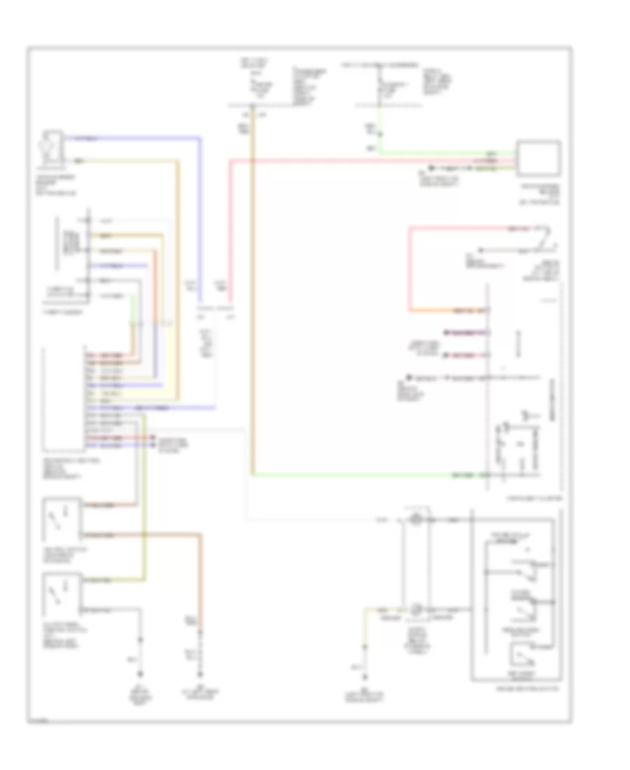
AIR CONDITIONING
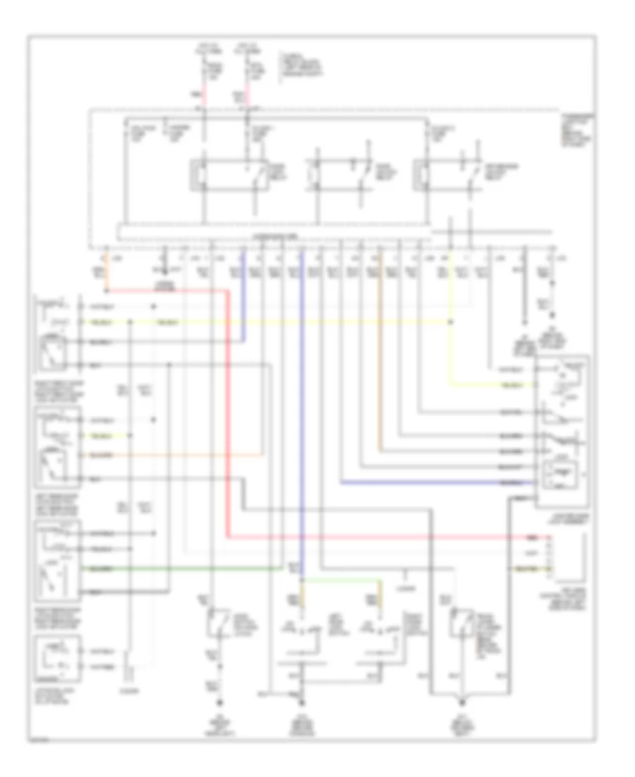
Heater Wiring Diagram for Mazda 3 SP23 2005

List of elements for Heater Wiring Diagram for Mazda 3 SP23 2005:
- (behind left headlight) g1
- (behind left side of dash) g7
- A/c fuse 10a
- Blower motor (behind right side of dash)
- Blower relay (in fuse and relay box)
- Climate control unit
- Defogger system
- Fan switch
- Fuse and relay box (left rear of engine compt)
- Heater fuse 40a
- Hot at all times
- Hot in run
- J-01
- Passenger junction box (behind right side of dash)
- Red
- Resistor (behind right side of dash)
- W/o a/c
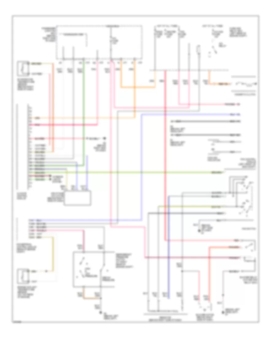
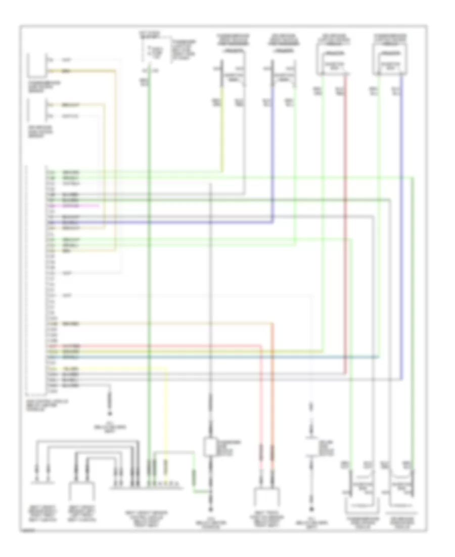
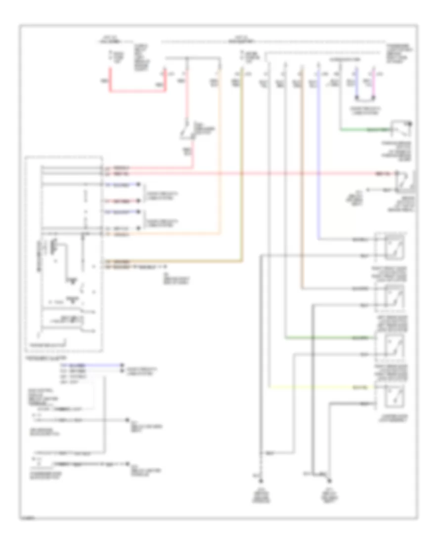
Manual A/C Wiring Diagram for Mazda 3 SP23 2005
List of elements for Manual A/C Wiring Diagram for Mazda 3 SP23 2005:
- (behind left headlight) g1
- (behind left side of dash) g7
- 1an
- 1ap
- 2aa
- 2ak
- A/c fuse 10a
- A/c mag fuse 10a
- A/c relay
- Air intake actuator (behind right side of dash)
- Blower motor (behind right side of dash)
- Blower relay (in fuse and relay box)
- Climate control module
- Cooling fan motor
- Engine coolant temperature sensor (on top rear of engine)
- Evaporator temperature sensor (behind right side of dash)
- Fan control module (left front of eng compt)
- Fan fuse 40a
- Fan switch
- Fuse and relay box (left rear of engine compt)
- G1 (behind left headlight)
- G2 (behind left headlight)
- G8 (behind right end of dash)
- Heater fuse 40a
- High & low pressure
- Hot at all times
- Hot in run
- Interior lights system
- J-01
- J-03
- J-04
- Magnetic clutch
- Medium pressure
- Microcomputer
- Nca
- Passenger junction box (behind right side of dash)
- Pnk
- Pnk/ red
- Pnk/red
- Powertrain control module (rear of engine compt)
- Red
- Refrigerant pressure switch (at right rear of engine compt)
- Resistor (behind right side of dash)
- Room fuse 15a
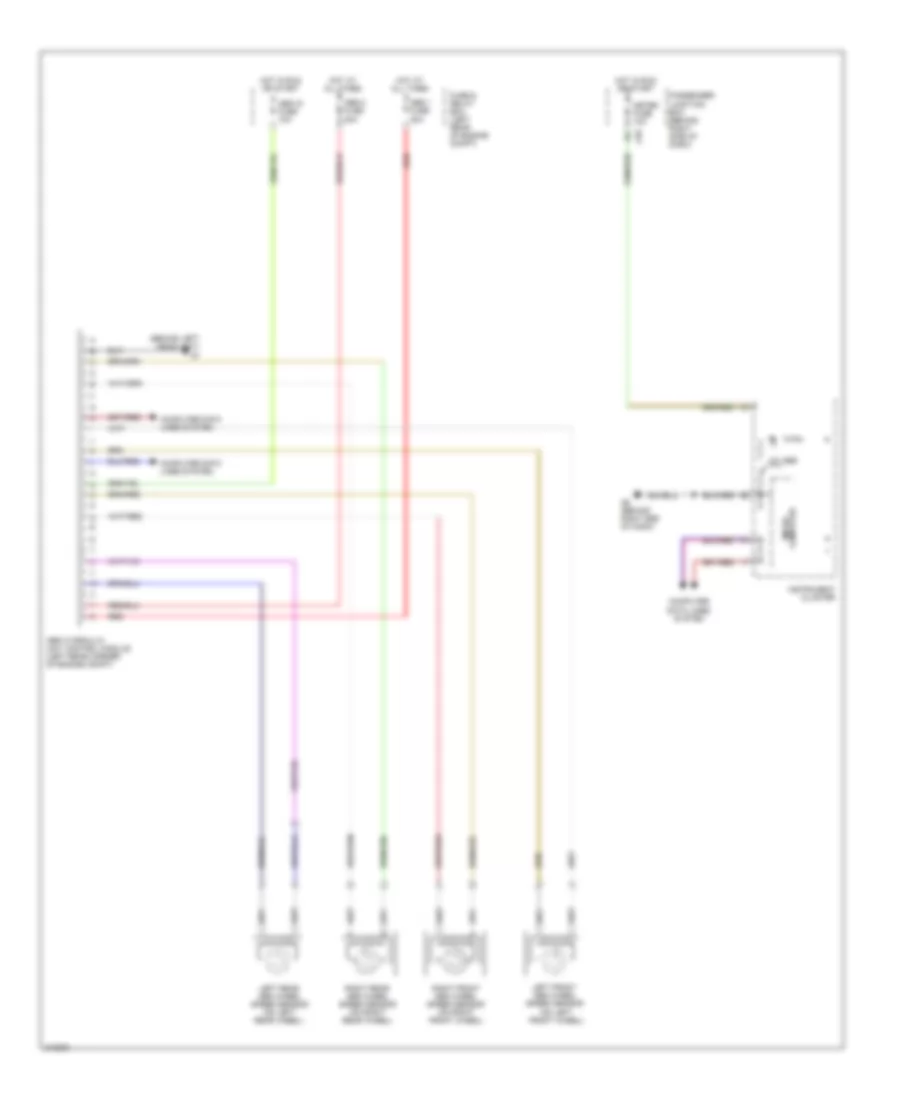
ANTI-LOCK BRAKES
Anti-lock Brakes Wiring Diagram for Mazda 3 SP23 2005
List of elements for Anti-lock Brakes Wiring Diagram for Mazda 3 SP23 2005:
- (behind left headlight) g1
- (on left front wheel)
- 4w abs
- Abs 1 fuse 30a
- Abs 2 fuse 20a
- Abs hydraulic unit control module (left rear corner of engine compt)
- Abs ig fuse 10a
- Computer data lines system
- Fuse & relay box (left rear of engine compt)
- G8 (behind right end of dash)
- Hot at all times
- Hot in run or start
- Instrument cluster
- J-03
- Left front abs wheel speed sensor
- Left rear abs wheel speed sensor (on left rear wheel)
- Meter fuse 10a
- Micro- computer
- Passenger junction box (behind right side of dash)
- Red
- Right front abs wheel speed sensor (on right front wheel)
- Right rear abs wheel speed sensor (on right rear wheel)
ANTI-THEFT
Anti-theft Alarm Wiring Diagram for Mazda 3 SP23 2005
List of elements for Anti-theft Alarm Wiring Diagram for Mazda 3 SP23 2005:
- 4 door
- 5 door
- Btn fuse 40a
- Cpu pwr fuse 10a
- D/lock 1 fuse 25a
- D/lock 2 fuse 15a
- Door lock relay
- Door unlock relay
- Driver-side unlock relay
- Fuse & relay block (left rear of engine compt)
- G11 (below driver's seat)
- G12 (behind center console)
- G2 (behind left headlight)
- G7 (behind left end of dash)
- G8 (behind right end of dash)
- Hazard fuse 15a
- Hood switch (on hood latch)
- Horns system
- Hot at all times
- J-01
- J-02
- J-03 c
- J-04
- J-05
- J-06
- Keyless control module (behind left side of dash)
- Left door lock switch
- Left rear door latch switch/ left rear door lock actuator
- Liftgate lock actuator (in liftgate)
- Lock
- Master door lock assembly
- Microcomputer
- Passenger junction box (behind right side of dash)
- Red
- Reset
- Right door lock switch
- Right front door latch switch/ right front door lock actuator
- Right rear door latch switch/ right rear door lock actuator
- Room fuse 15a
- Set
- Trunk lid key cylinder switch (rear center of trunk lid)
- Un- lock
- Unlock
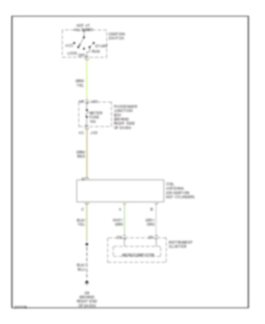
Immobilizer Wiring Diagram for Mazda 3 SP23 2005
List of elements for Immobilizer Wiring Diagram for Mazda 3 SP23 2005:
- Acc
- Coil antenna (on ignition key cylinder)
- G8 (behind right end of dash)
- Hot at all times
- Ignition switch
- Instrument cluster
- J-03
- Lock
- Meter fuse 10a
- Microcomputer
- Off
- Passenger junction box (behind right side of dash)
- Run
- Start
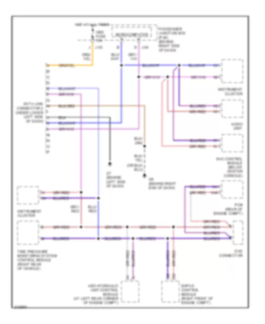
COMPUTER DATA LINES
Computer Data Lines Wiring Diagram for Mazda 3 SP23 2005
List of elements for Computer Data Lines Wiring Diagram for Mazda 3 SP23 2005:
- 1ai
- 1am
- Abs hydraulic unit/control module (at left rear corner of engine compt)
- Audio unit
- D j-04
- D-02 connector
- Data link h connector 2 under lower left side j
- Ehpas control module (right front of engine compt)
- G7 (behind left side of dash)
- G8 (behind right end of dash)
- Hot at all times
- Instrument cluster
- J j-03
- Microcomputer
- Obd fuse 10a
- Of dash) k
- Passenger junction box (pjb) (behind right side of dash)
- Pcm (rear of engine compt)
- Sas control module (below center console)
- Tire pressure monitoring system control module (right rear of vehicle)
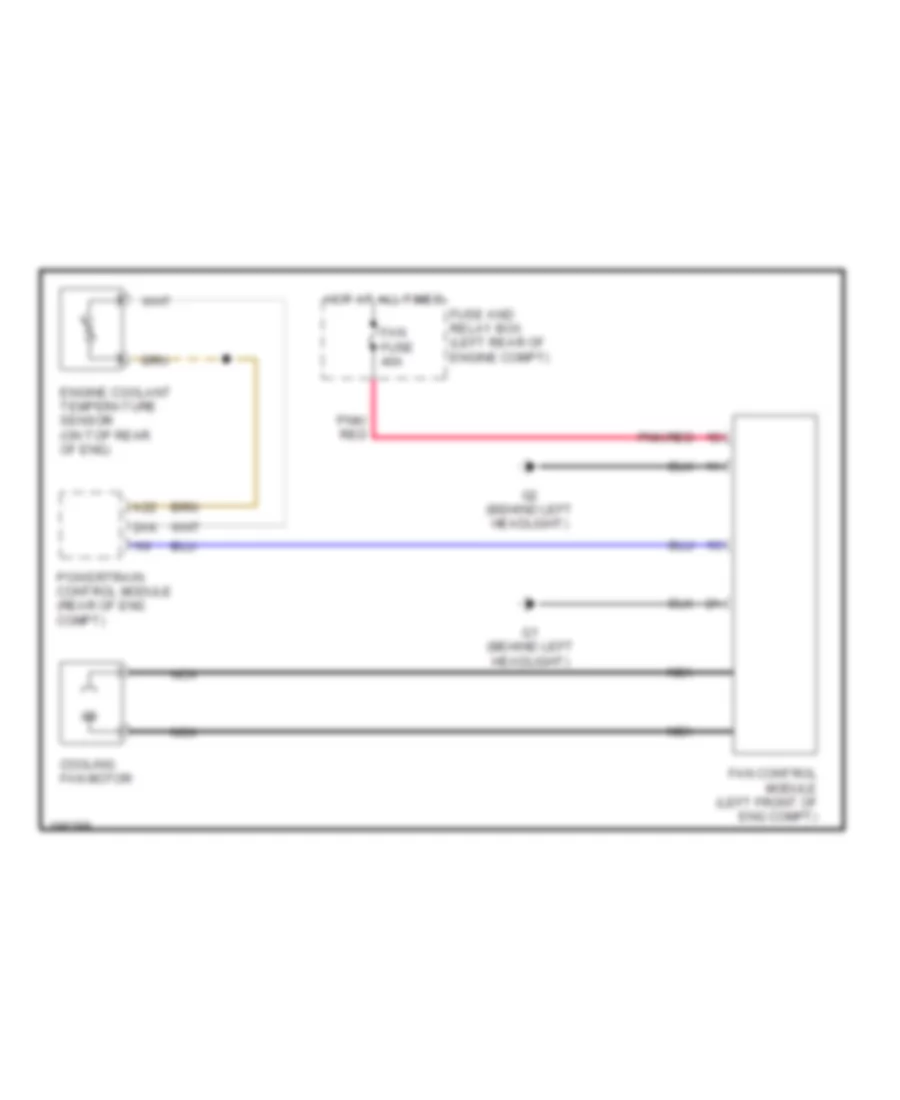
COOLING FAN
Cooling Fan Wiring Diagram for Mazda 3 SP23 2005
List of elements for Cooling Fan Wiring Diagram for Mazda 3 SP23 2005:
- 2ak
- A22
- Cooling fan motor
- Engine coolant temperature sensor (on top rear of eng)
- Fan control module (left front of eng compt)
- Fan fuse 40a
- Fuse and relay box (left rear of engine compt)
- G1 (behind left headlight)
- G2 (behind left headlight)
- Hot at all times
- Nca
- Pnk/ red
- Pnk/red
- Powertrain control module (rear of eng compt)
CRUISE CONTROL
Cruise Control Wiring Diagram for Mazda 3 SP23 2005
List of elements for Cruise Control Wiring Diagram for Mazda 3 SP23 2005:
- (left front of engine compt)
- 0922-202
- 0922-203
- 1ad
- 1ai
- 1am
- A/t
- Brake switch 2 (at top of brake pedal)
- Cancel switch
- Clock- spring (below steering wheel)
- Clutch pedal position switch (m/t) (behind left side of dash)
- Computer data lines system
- Cruise control switch
- Cruise main ind
- Cruise main switch
- Cruise set ind
- Driver's seat
- Eng bar 1 fuse 10a
- Fuse & relay box (left rear of engine compt)
- G11 (below
- G11 (below driver's seat)
- G5 (left front of engine compt)
- G6 (at left rear of engine)
- G8 (behind right end of dash)
- Hot in run or start
- Hot w/ main relay energized
- Instrument cluster
- J-03
- M/t
- Meter fuse 10a
- Microcomputer
- Nca
- Neutral switch (near rear of engine)
- Passenger junction box (behind right side of dash)
- Position throttle
- Powertrain control module (rear of engine compt)
- Resume/accel switch
- Sensor
- Set/coast switch
- Throttle actuator
- Throttle body
- Vehicle speed sensor (a/t) (on transaxle)
- Vehicle speed sensor (m/t) (on transaxle)
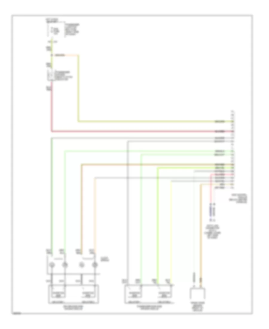
DEFOGGERS
Defoggers Wiring Diagram for Mazda 3 SP23 2005
List of elements for Defoggers Wiring Diagram for Mazda 3 SP23 2005:
- A/c fuse 10a
- Blower relay (in fuse and relay box)
- Climate control unit
- Defog fuse 40a
- Door
- Filament
- Fuse & relay box (left rear of engine compt)
- G11 (below driver's seat)
- G12 (below center console)
- G14 (behind rear seat)
- Hazard fuse 15a
- Hot at all times
- Hot in run
- J-01 i
- J-01 n
- J-04
- Left power outside mirror
- M def fuse 7.5a
- Microcomputer
- Mirror heater
- Passenger junction box (behind right side of dash)
- Rear window defroster relay
- Red
- Right power outside mirror
- W/ air conditioning
- W/o air conditioning
- Z j-05
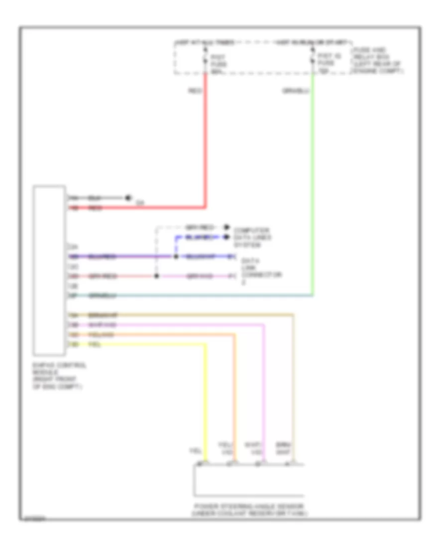
ELECTRONIC POWER STEERING
Electronic Power Steering Wiring Diagram for Mazda 3 SP23 2005
List of elements for Electronic Power Steering Wiring Diagram for Mazda 3 SP23 2005:
- Computer data lines system
- Data link connector
- Ehpas control module (right front of eng compt)
- Fuse and relay box (left rear of engine compt)
- Hot at all times
- Hot in run or start
- P/st fuse 80a
- P/st ig fuse 10a
- Power steering angle sensor (under coolant reservoir tank)
- Red
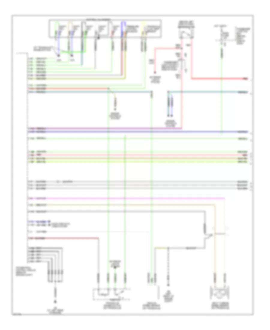
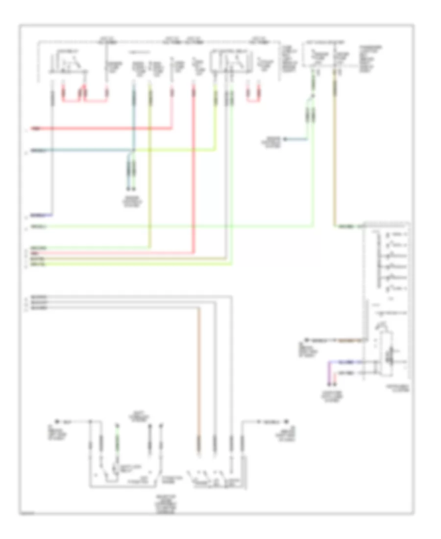
ENGINE PERFORMANCE
2.0L
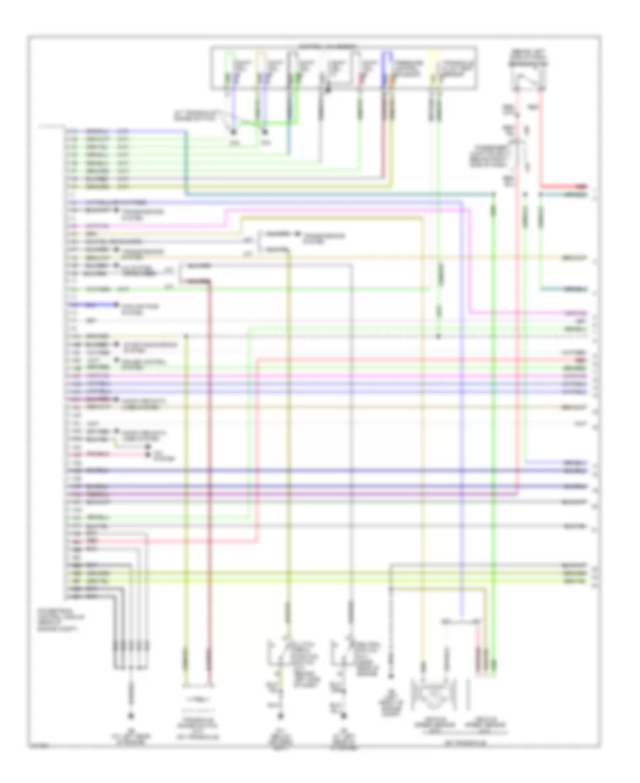
2.0L, Engine Performance Wiring Diagram, California (1 of 4) for Mazda 3 SP23 2005
List of elements for 2.0L, Engine Performance Wiring Diagram, California (1 of 4) for Mazda 3 SP23 2005:
- (a/t)
- (at transaxle range switch)
- (behind left side of dash) brake switch
- (on transaxle)
- 1aa
- 1ab
- 1ac
- 1ad
- 1ae
- 1af
- 1ag
- 1ah
- 1ai
- 1aj
- 1ak
- 1al
- 1am
- 1an
- 1ao
- 1ap
- 1aq
- 1ar
- 1as
- 1at
- 1au
- 1av
- 1aw
- 1ax
- 1ay
- 1az
- 1ba
- 1bb
- 1bc
- 1bd
- 1be
- 1bf
- 1bg
- 1bh
- A/c system
- A/t
- Clutch pedal position switch (m/t) (behind left side of dash)
- Computer data lines system
- Control valve body
- Cooling fans system
- Cruise control system
- G11 (below driver's seat)
- G16
- G5 (left front of engine compt)
- G6 (at left rear of engine)
- G6 (at left rear of of engine)
- J-01
- J-05
- M/t
- Neutral switch (m/t) (near rear of engine)
- Passenger junction box (behind right side of dash)
- Powertrain control module (rear of engine compt)
- Pressure control solenoid
- Red
- Shift sol a
- Shift sol b
- Shift sol c
- Shift sol d
- Shift sol e
- Starting/charging system
- Transaxle fluid temp sensor
- Transaxle range switch (a/t) (on transaxle)
- Transmissions system
- Vehicle speed sensor (a/t)
- Vehicle speed sensor (m/t)
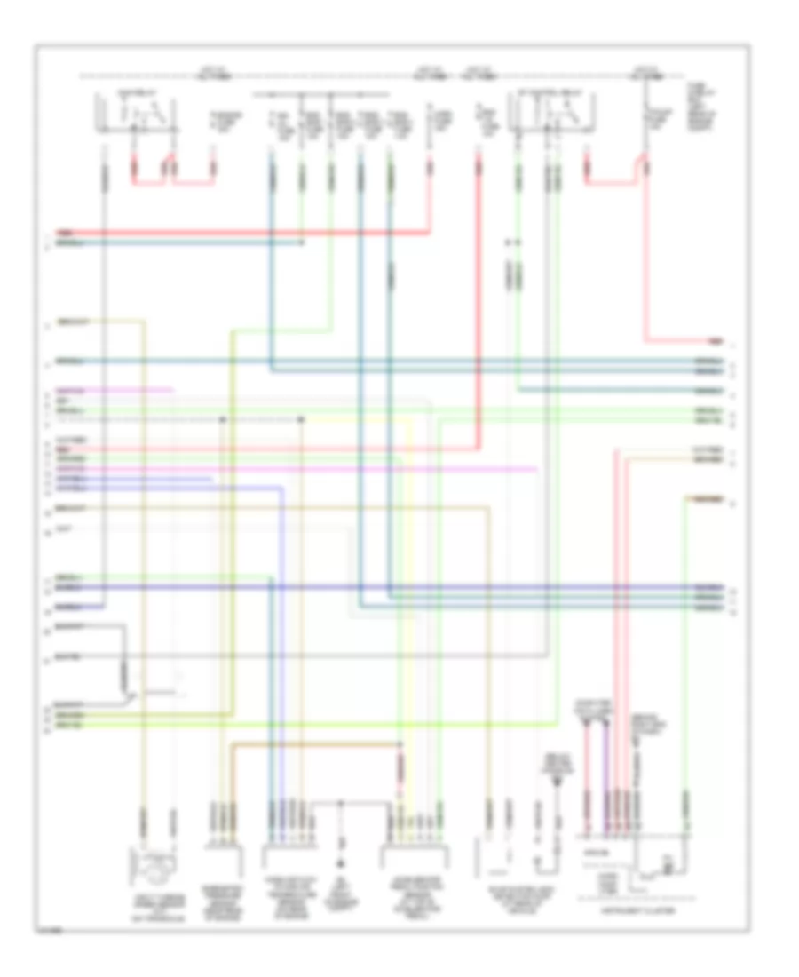
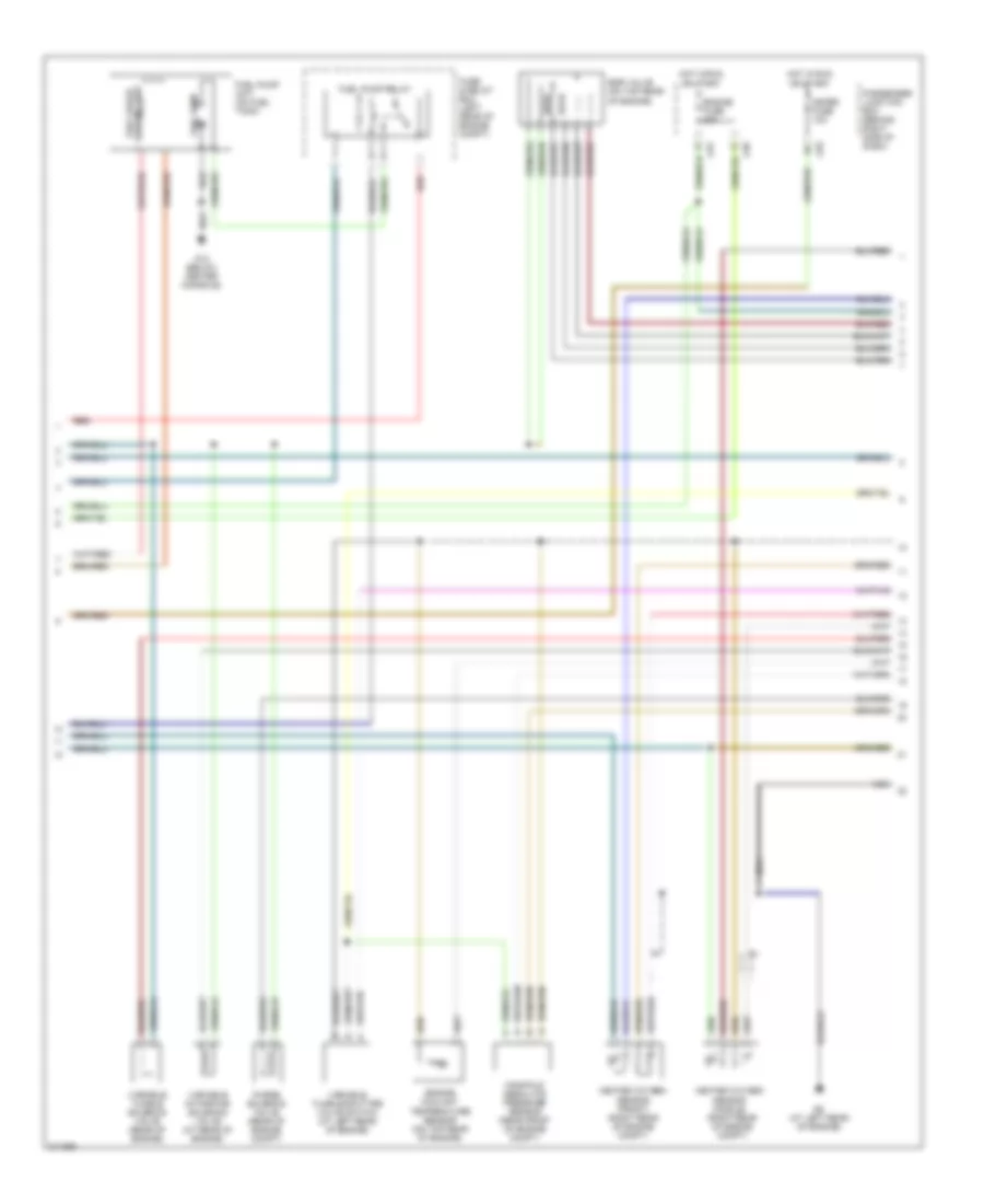
2.0L, Engine Performance Wiring Diagram, California (2 of 4) for Mazda 3 SP23 2005
List of elements for 2.0L, Engine Performance Wiring Diagram, California (2 of 4) for Mazda 3 SP23 2005:
- (behind right end of dash) g8
- (below center console) g12
- Accelerator pedal position sensor (at top of accelerator pedal)
- Barometric pressure sensor (near rear of engine)
- Computer data lines system
- Egi inj fuse 10a
- Eng + b fuse 10a
- Eng bar 1 fuse 10a
- Eng bar 2 fuse 10a
- Eng bar 3 fuse 10a
- Eng bar 4 fuse 10a
- Engine fuse 30a
- Et control relay
- Evap system leak detection pump (at rear of vehicle)
- F/pump fuse 15a
- Fuse & relay box (left rear of engine compt)
- G5 (left front of engine compt)
- Horn fuse 15a
- Hot at all times
- Input turbine speed sensor (a/t) (on transaxle)
- Instrument cluster
- Main relay
- Mass air flow/ intake air temperature sensor (on rear of engine
- Micro comp- uter
- Mil ind
- Red
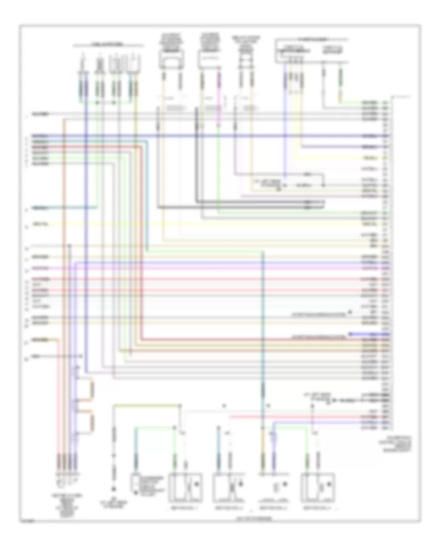
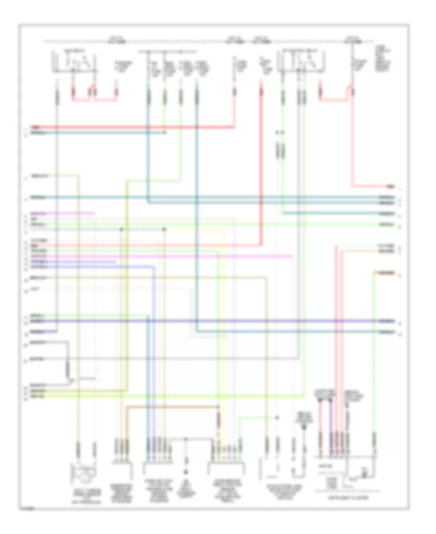
2.0L, Engine Performance Wiring Diagram, California (3 of 4) for Mazda 3 SP23 2005
List of elements for 2.0L, Engine Performance Wiring Diagram, California (3 of 4) for Mazda 3 SP23 2005:
- Egr valve (on top rear of engine)
- Engine coolant temperature sensor (on top rear of engine)
- Engine fuse 20a
- Fuel gauge sending unit
- Fuel pump
- Fuel pump relay
- Fuel pump unit (on fuel tank)
- Fuse & relay box (left rear of engine compt)
- G12 (below center console)
- G6 (at left rear of engine)
- Heated oxygen sensor (front) (right rear of engine compt)
- Heated oxygen sensor (middle) (right rear of engine compt)
- Hot in run or start
- J-01
- J-03
- J-05
- Manifold absolute pressure sensor (near front of engine compt)
- Meter fuse 10a
- Nca
- Passenger junction box (behind right side of dash)
- Purge solenoid valve (rear of engine compt)
- Red
- Variable intake-air solenoid valve (at rear of engine)
- Variable tumble shutter valve switch (at left rear of engine)
- Variable tumble solenoid valve (rear of engine)
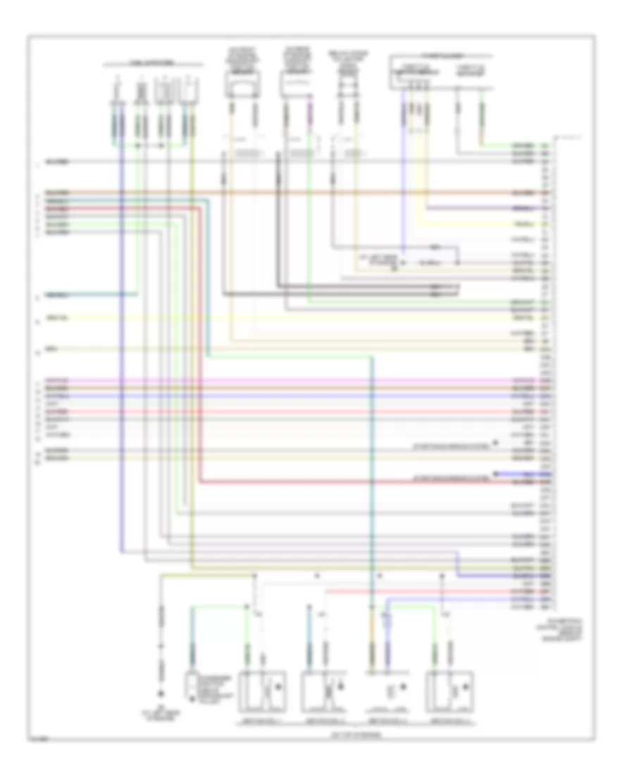
2.0L, Engine Performance Wiring Diagram, California (4 of 4) for Mazda 3 SP23 2005
List of elements for 2.0L, Engine Performance Wiring Diagram, California (4 of 4) for Mazda 3 SP23 2005:
- (at left rear of engine) g6
- (below intake collector) knock sensor
- (on front of engine) crankshaft position sensor
- (on rear of engine) camshaft position sensor
- (on top of engine)
- 2aa
- 2ab
- 2ac
- 2ad
- 2ae
- 2af
- 2ag
- 2ah
- 2ai
- 2aj
- 2ak
- 2al
- 2am
- 2an
- 2ao
- 2ap
- 2aq
- 2ar
- 2as
- 2at
- 2au
- 2av
- 2aw
- 2ax
- 2ay
- 2az
- 2ba
- 2bb
- 2bc
- 2bd
- 2be
- 2bf
- 2bg
- 2bh
- Condenser (ignition) (above crankshaft pulley)
- Fuel injectors
- G6 (at left rear of engine)
- Heated oxygen sensor (rear) (at rear of engine compt)
- Ignition coil 1
- Ignition coil 2
- Ignition coil 3
- Ignition coil 4
- Nca
- Powertrain control module (rear of engine compt)
- Starting/charging system
- Throttle actuator
- Throttle body
- Throttle position sensor
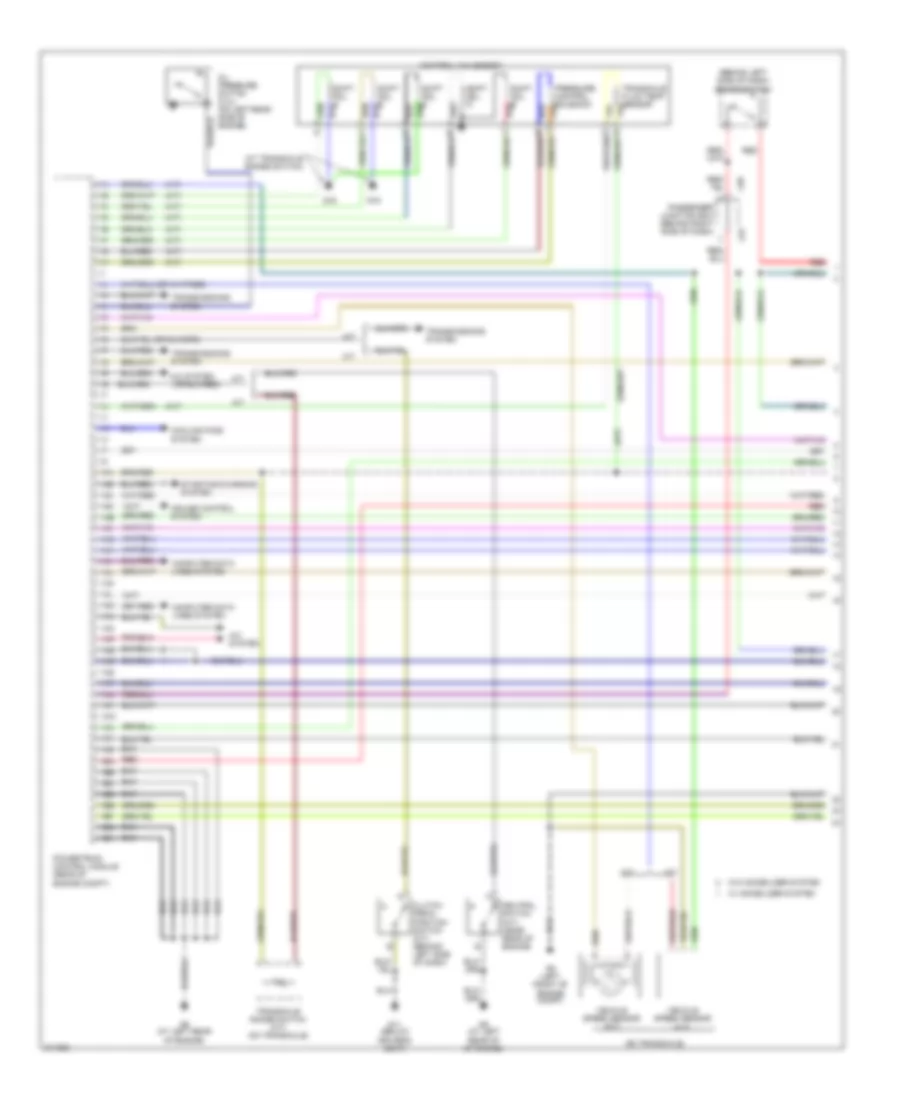
2.0L, Engine Performance Wiring Diagram, Except California (1 of 4) for Mazda 3 SP23 2005
List of elements for 2.0L, Engine Performance Wiring Diagram, Except California (1 of 4) for Mazda 3 SP23 2005:
- (a/t)
- (at transaxle range switch)
- (behind left side of dash) brake switch
- (on transaxle)
- 1aa
- 1ab
- 1ac
- 1ad
- 1ae
- 1af
- 1ag
- 1ah
- 1ai
- 1aj
- 1ak
- 1al
- 1am
- 1an
- 1ao
- 1ap
- 1aq
- 1ar
- 1as
- 1at
- 1au
- 1av
- 1aw
- 1ax
- 1ay
- 1az
- 1ba
- 1bb
- 1bc
- 1bd
- 1be
- 1bf
- 1bg
- 1bh
- A/c system
- A/t
- Clutch pedal position switch (m/t) (behind left side of dash)
- Computer data lines system
- Control valve body
- Cooling fans system
- Cruise control system
- Driver's seat)
- G11 (below
- G16
- G5 (left front of engine compt)
- G6 (at left rear of engine)
- G6 (at left rear of of engine)
- J-01
- J-05
- M/t
- Neutral switch (m/t) (near rear of engine)
- Oil pressure switch (2.3l) (on left rear side of engine)
- Passenger junction box (behind right side of dash)
- Powertrain control module (rear of engine compt)
- Pressure control solenoid
- Red
- Shift sol a
- Shift sol b
- Shift sol c
- Shift sol d
- Shift sol e
- Starting/charging system
- Transaxle fluid temp sensor
- Transaxle range switch (a/t) (on transaxle)
- Transmissions system
- Vehicle speed sensor (a/t)
- Vehicle speed sensor (m/t)
- W/ immobilizer system
- W/o immobilizer system
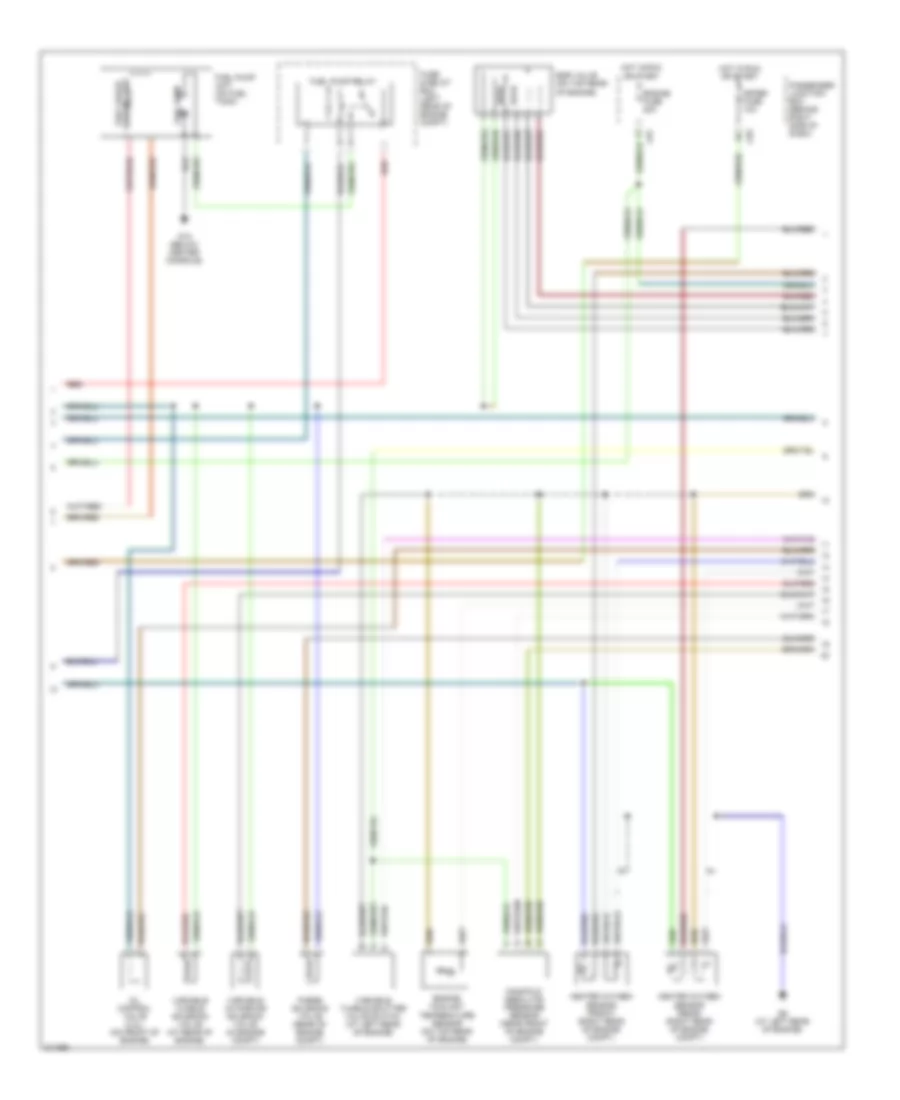
2.0L, Engine Performance Wiring Diagram, Except California (2 of 4) for Mazda 3 SP23 2005
List of elements for 2.0L, Engine Performance Wiring Diagram, Except California (2 of 4) for Mazda 3 SP23 2005:
- (behind right end of dash) g8
- (below center console) g12
- Accelerator pedal position sensor (at top of accelerator pedal)
- Barometric pressure sensor (near rear of engine)
- Computer data lines system
- Egi inj fuse 15a
- Eng b + fuse 10a
- Eng bar 1 fuse 10a
- Eng bar 2 fuse 10a
- Eng bar 3 fuse 10a
- Engine fuse 30a
- Et control relay
- Evap system leak detection pump (at rear of vehicle)
- F/pump fuse 15a
- Fuse & relay box (left rear of engine compt)
- G5 (left front of engine compt)
- Horn fuse 15a
- Hot at all times
- Input turbine speed sensor (a/t) (on transaxle)
- Instrument cluster
- Main relay
- Mass air flow/ intake air temperature sensor (on rear of engine
- Micro comp- uter
- Mil ind
- Red
2.0L, Engine Performance Wiring Diagram, Except California (3 of 4) for Mazda 3 SP23 2005
List of elements for 2.0L, Engine Performance Wiring Diagram, Except California (3 of 4) for Mazda 3 SP23 2005:
- Egr valve (on top rear of engine)
- Engine coolant temperature sensor (on top rear of engine)
- Engine fuse 20a
- Fuel gauge sending unit
- Fuel pump
- Fuel pump relay
- Fuel pump unit (on fuel tank)
- Fuse & relay box (left rear of engine compt)
- G12 (below center console)
- G6 (at left rear of engine)
- Heated oxygen sensor (front) (right rear of engine compt)
- Heated oxygen sensor (rear) (right rear of engine compt)
- Hot in run or start
- J-01
- J-03
- Manifold absolute pressure sensor (near front of engine compt)
- Meter fuse 10a
- Oil control valve (2.3l) (on front of engine)
- Passenger junction box (behind right side of dash)
- Purge solenoid valve (rear of engine compt)
- Red
- Variable intake-air solenoid valve (in engine compt)
- Variable tumble shutter valve switch (at left rear of engine)
- Variable tumble solenoid valve (at rear of engine)
2.0L, Engine Performance Wiring Diagram, Except California (4 of 4) for Mazda 3 SP23 2005
List of elements for 2.0L, Engine Performance Wiring Diagram, Except California (4 of 4) for Mazda 3 SP23 2005:
- (at left rear of engine) g6
- (below intake collector) knock sensor
- (on front of engine) crankshaft position sensor
- (on rear of engine) camshaft position sensor
- (on top of engine)
- 2aa
- 2ab
- 2ac
- 2ad
- 2ae
- 2af
- 2ag
- 2ah
- 2ai
- 2aj
- 2ak
- 2al
- 2am
- 2an
- 2ao
- 2ap
- 2aq
- 2ar
- 2as
- 2at
- 2au
- 2av
- 2aw
- 2ax
- 2ay
- 2az
- 2ba
- 2bb
- 2bc
- 2bd
- 2be
- 2bf
- 2bg
- 2bh
- Condenser (ignition) (above crankshaft pulley)
- Fuel injectors
- G6 (at left rear of engine)
- Ignition coil 1
- Ignition coil 2
- Ignition coil 3
- Ignition coil 4
- Nca
- Powertrain control module (rear of engine compt)
- Starting/charging system
- Throttle actuator
- Throttle body
- Throttle position sensor
2.3L
2.3L, Engine Performance Wiring Diagram, California (1 of 4) for Mazda 3 SP23 2005
List of elements for 2.3L, Engine Performance Wiring Diagram, California (1 of 4) for Mazda 3 SP23 2005:
- (a/t)
- (at transaxle range switch)
- (behind left side of dash) brake switch
- (on transaxle)
- 1aa
- 1ab
- 1ac
- 1ad
- 1ae
- 1af
- 1ag
- 1ah
- 1ai
- 1aj
- 1ak
- 1al
- 1am
- 1an
- 1ao
- 1ap
- 1aq
- 1ar
- 1as
- 1at
- 1au
- 1av
- 1aw
- 1ax
- 1ay
- 1az
- 1ba
- 1bb
- 1bc
- 1bd
- 1be
- 1bf
- 1bg
- 1bh
- A/c system
- A/t
- Clutch pedal position switch (m/t) (behind left side of dash)
- Computer data lines system
- Control valve body
- Cooling fans system
- Cruise control system
- G11 (below driver's seat)
- G16
- G5 (left front of engine compt)
- G6 (at left rear of engine)
- G6 (at left rear of of engine)
- J-01
- J-05
- M/t
- Neutral switch (m/t) (near rear of engine)
- Passenger junction box (behind right side of dash)
- Powertrain control module (rear of engine compt)
- Pressure control solenoid
- Red
- Shift sol a
- Shift sol b
- Shift sol c
- Shift sol d
- Shift sol e
- Starting/charging system
- Transaxle fluid temp sensor
- Transaxle range switch (a/t) (on transaxle)
- Transmissions system
- Vehicle speed sensor (a/t)
- Vehicle speed sensor (m/t)
2.3L, Engine Performance Wiring Diagram, California (2 of 4) for Mazda 3 SP23 2005
List of elements for 2.3L, Engine Performance Wiring Diagram, California (2 of 4) for Mazda 3 SP23 2005:
- (behind right end of dash) g8
- (below center console) g12
- Accelerator pedal position sensor (at top of accelerator pedal)
- Barometric pressure sensor (near rear of engine)
- Computer data lines system
- Egi inj fuse 10a
- Eng + b fuse 10a
- Eng bar 1 fuse 10a
- Eng bar 2 fuse 10a
- Eng bar 3 fuse 10a
- Eng bar 4 fuse 10a
- Engine fuse 30a
- Et control relay
- Evap system leak detection pump (at rear of vehicle)
- F/pump fuse 15a
- Fuse & relay box (left rear of engine compt)
- G5 (left front of engine compt)
- Horn fuse 15a
- Hot at all times
- Input turbine speed sensor (a/t) (on transaxle)
- Instrument cluster
- Main relay
- Mass air flow/ intake air temperature sensor (on rear of engine
- Micro comp- uter
- Mil ind
- Red
2.3L, Engine Performance Wiring Diagram, California (3 of 4) for Mazda 3 SP23 2005
List of elements for 2.3L, Engine Performance Wiring Diagram, California (3 of 4) for Mazda 3 SP23 2005:
- Egr valve (on top rear of engine)
- Engine coolant temperature sensor (on top rear of engine)
- Engine fuse 20a
- Fuel gauge sending unit
- Fuel pump
- Fuel pump relay
- Fuel pump unit (on fuel tank)
- Fuse & relay box (left rear of engine compt)
- G12 (below center console)
- G6 (at left rear of engine)
- Heated oxygen sensor (front) (right rear of engine compt)
- Heated oxygen sensor (middle) (right rear of engine compt)
- Hot in run or start
- J-01
- J-03
- J-05
- Manifold absolute pressure sensor (near front of engine compt)
- Meter fuse 10a
- Nca
- Passenger junction box (behind right side of dash)
- Purge solenoid valve (rear of engine compt)
- Red
- Variable intake-air solenoid valve (at rear of engine)
- Variable tumble shutter valve switch (at left rear of engine)
- Variable tumble solenoid valve (rear of engine)
2.3L, Engine Performance Wiring Diagram, California (4 of 4) for Mazda 3 SP23 2005
List of elements for 2.3L, Engine Performance Wiring Diagram, California (4 of 4) for Mazda 3 SP23 2005:
- (at left rear of engine) g6
- (below intake collector) knock sensor
- (on front of engine) crankshaft position sensor
- (on rear of engine) camshaft position sensor
- (on top of engine)
- 2aa
- 2ab
- 2ac
- 2ad
- 2ae
- 2af
- 2ag
- 2ah
- 2ai
- 2aj
- 2ak
- 2al
- 2am
- 2an
- 2ao
- 2ap
- 2aq
- 2ar
- 2as
- 2at
- 2au
- 2av
- 2aw
- 2ax
- 2ay
- 2az
- 2ba
- 2bb
- 2bc
- 2bd
- 2be
- 2bf
- 2bg
- 2bh
- Condenser (ignition) (above crankshaft pulley)
- Fuel injectors
- G6 (at left rear of engine)
- Heated oxygen sensor (rear) (at rear of engine compt)
- Ignition coil 1
- Ignition coil 2
- Ignition coil 3
- Ignition coil 4
- Nca
- Powertrain control module (rear of engine compt)
- Starting/charging system
- Throttle actuator
- Throttle body
- Throttle position sensor
2.3L, Engine Performance Wiring Diagram, Except California (1 of 4) for Mazda 3 SP23 2005
List of elements for 2.3L, Engine Performance Wiring Diagram, Except California (1 of 4) for Mazda 3 SP23 2005:
- (a/t)
- (at transaxle range switch)
- (behind left side of dash) brake switch
- (on transaxle)
- 1aa
- 1ab
- 1ac
- 1ad
- 1ae
- 1af
- 1ag
- 1ah
- 1ai
- 1aj
- 1ak
- 1al
- 1am
- 1an
- 1ao
- 1ap
- 1aq
- 1ar
- 1as
- 1at
- 1au
- 1av
- 1aw
- 1ax
- 1ay
- 1az
- 1ba
- 1bb
- 1bc
- 1bd
- 1be
- 1bf
- 1bg
- 1bh
- A/c system
- A/t
- Clutch pedal position switch (m/t) (behind left side of dash)
- Computer data lines system
- Control valve body
- Cooling fans system
- Cruise control system
- Driver's seat)
- G11 (below
- G16
- G5 (left front of engine compt)
- G6 (at left rear of engine)
- G6 (at left rear of of engine)
- J-01
- J-05
- M/t
- Neutral switch (m/t) (near rear of engine)
- Oil pressure switch (2.3l) (on left rear side of engine)
- Passenger junction box (behind right side of dash)
- Powertrain control module (rear of engine compt)
- Pressure control solenoid
- Red
- Shift sol a
- Shift sol b
- Shift sol c
- Shift sol d
- Shift sol e
- Starting/charging system
- Transaxle fluid temp sensor
- Transaxle range switch (a/t) (on transaxle)
- Transmissions system
- Vehicle speed sensor (a/t)
- Vehicle speed sensor (m/t)
- W/ immobilizer system
- W/o immobilizer system
2.3L, Engine Performance Wiring Diagram, Except California (2 of 4) for Mazda 3 SP23 2005
List of elements for 2.3L, Engine Performance Wiring Diagram, Except California (2 of 4) for Mazda 3 SP23 2005:
- (behind right end of dash) g8
- (below center console) g12
- Accelerator pedal position sensor (at top of accelerator pedal)
- Barometric pressure sensor (near rear of engine)
- Computer data lines system
- Egi inj fuse 15a
- Eng b + fuse 10a
- Eng bar 1 fuse 10a
- Eng bar 2 fuse 10a
- Eng bar 3 fuse 10a
- Engine fuse 30a
- Et control relay
- Evap system leak detection pump (at rear of vehicle)
- F/pump fuse 15a
- Fuse & relay box (left rear of engine compt)
- G5 (left front of engine compt)
- Horn fuse 15a
- Hot at all times
- Input turbine speed sensor (a/t) (on transaxle)
- Instrument cluster
- Main relay
- Mass air flow/ intake air temperature sensor (on rear of engine
- Micro comp- uter
- Mil ind
- Red
2.3L, Engine Performance Wiring Diagram, Except California (3 of 4) for Mazda 3 SP23 2005
List of elements for 2.3L, Engine Performance Wiring Diagram, Except California (3 of 4) for Mazda 3 SP23 2005:
- Egr valve (on top rear of engine)
- Engine coolant temperature sensor (on top rear of engine)
- Engine fuse 20a
- Fuel gauge sending unit
- Fuel pump
- Fuel pump relay
- Fuel pump unit (on fuel tank)
- Fuse & relay box (left rear of engine compt)
- G12 (below center console)
- G6 (at left rear of engine)
- Heated oxygen sensor (front) (right rear of engine compt)
- Heated oxygen sensor (rear) (right rear of engine compt)
- Hot in run or start
- J-01
- J-03
- Manifold absolute pressure sensor (near front of engine compt)
- Meter fuse 10a
- Oil control valve (2.3l) (on front of engine)
- Passenger junction box (behind right side of dash)
- Purge solenoid valve (rear of engine compt)
- Red
- Variable intake-air solenoid valve (in engine compt)
- Variable tumble shutter valve switch (at left rear of engine)
- Variable tumble solenoid valve (at rear of engine)
2.3L, Engine Performance Wiring Diagram, Except California (4 of 4) for Mazda 3 SP23 2005
List of elements for 2.3L, Engine Performance Wiring Diagram, Except California (4 of 4) for Mazda 3 SP23 2005:
- (at left rear of engine) g6
- (below intake collector) knock sensor
- (on front of engine) crankshaft position sensor
- (on rear of engine) camshaft position sensor
- (on top of engine)
- 2aa
- 2ab
- 2ac
- 2ad
- 2ae
- 2af
- 2ag
- 2ah
- 2ai
- 2aj
- 2ak
- 2al
- 2am
- 2an
- 2ao
- 2ap
- 2aq
- 2ar
- 2as
- 2at
- 2au
- 2av
- 2aw
- 2ax
- 2ay
- 2az
- 2ba
- 2bb
- 2bc
- 2bd
- 2be
- 2bf
- 2bg
- 2bh
- Condenser (ignition) (above crankshaft pulley)
- Fuel injectors
- G6 (at left rear of engine)
- Ignition coil 1
- Ignition coil 2
- Ignition coil 3
- Ignition coil 4
- Nca
- Powertrain control module (rear of engine compt)
- Starting/charging system
- Throttle actuator
- Throttle body
- Throttle position sensor
EXTERIOR LIGHTS
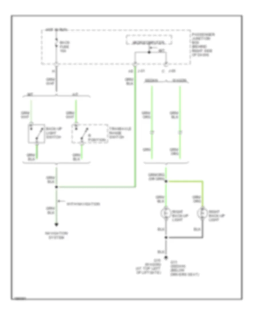
Back-up Lamps Wiring Diagram for Mazda 3 SP23 2005
List of elements for Back-up Lamps Wiring Diagram for Mazda 3 SP23 2005:
- A/t
- Back fuse 10a
- Back-up light switch
- G11 (sedan) (below drivers seat)
- G15 (wagon) (at top left of liftgate)
- Hot in run
- J-01 ae
- J-05 c
- M/t
- Microcomputer
- Navigation system
- Passenger junction box (behind right side of dash)
- R position
- Right back-up light
- Sedan
- Transaxle range switch
- Wagon
- With navigation
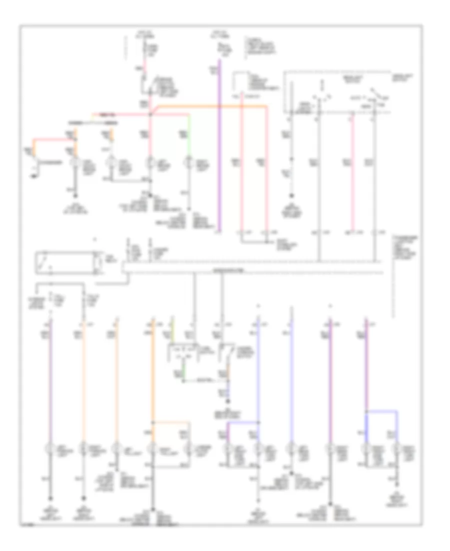
Exterior Lamps Wiring Diagram for Mazda 3 SP23 2005
List of elements for Exterior Lamps Wiring Diagram for Mazda 3 SP23 2005:
- 0140-101
- 1au
- Auto
- Brake switch (behind left side of dash)
- Btn fuse 40a
- Condenser
- Cpu pwr fuse 10a
- Fuse & relay block (left rear of engine compt)
- G1 (behind left headlight)
- G11 (sedan) (below driver's seat)
- G11 (sedan) (below drivers seat)
- G12 (wagon) (below center console)
- G13 (wagon) (top left side of liftgate)
- G14 (sedan) (behind rear seat)
- G15 (top left of liftgate)
- G3 (behind right headlight)
- G8 (behind right end of dash)
- Hazard fuse 15a
- Hazard warning switch
- Head
- Head- lights system
- Headlight switch
- High mount brake light
- Horn fuse 15a
- Hot at all times
- Interior lights system
- J-01
- J-01 ak
- J-01 k
- J-01 l
- J-03
- J-04
- J-05
- J-05 ak
- J-05 as
- Left brake light
- Left front side turn light
- Left front turn light
- Left parking light
- Left rear turn light
- Left taillight
- License plate light
- Microcomputer
- Off
- Passenger junction box (behind right side of dash)
- Pcm (rear of engine compartment)
- Red
- Right brake light
- Right front side turn light
- Right front turn light
- Right parking light
- Right rear turn light
- Right taillight
- Sedan
- Shift interlock system
- Tail l fuse 7.5a
- Tail r fuse 7.5a
- Tns
- Tns relay
- Turn switch
- Wagon
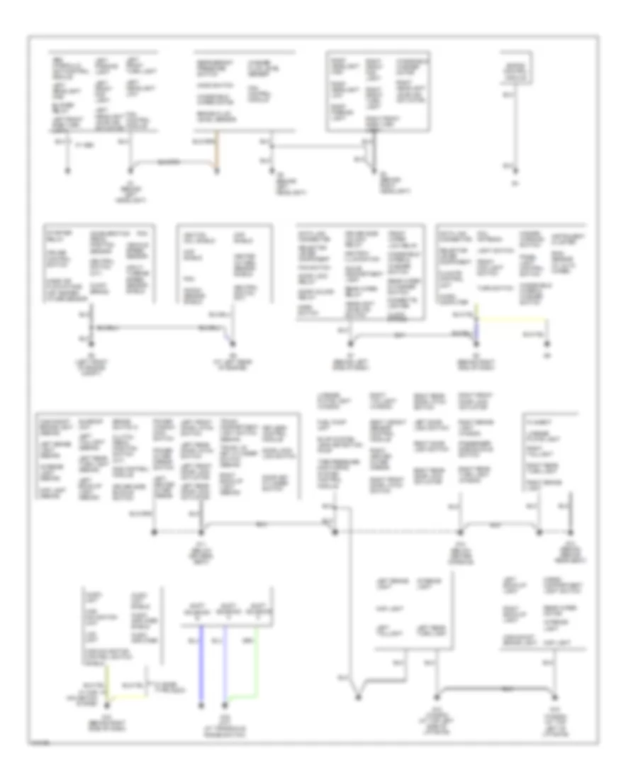
GROUND DISTRIBUTION
Ground Distribution Wiring Diagram for Mazda 3 SP23 2005
List of elements for Ground Distribution Wiring Diagram for Mazda 3 SP23 2005:
- (behind left headlight)
- (wagon) (at top left of liftgate)
- Abs hydraulic unit/control module
- Acceleration pedal position sensor
- Ashtray illumination
- Audio amplifier
- Audio amplifier shield
- Audio unit
- Audio unit shield
- Blower relay
- Brake fluid level sensor
- Brake switch 2
- Car navigation control switch shield
- Car navigation unit
- Cargo compartment light switch
- Cigarette lighter
- Ckp shield
- Climate control unit
- Clock spring
- Clutch pedal position switch (m/t)
- Cmp shield
- Coil antenna
- Cruise control switch
- Data link connector
- Door key cylinder switch
- Door lock relay
- Door lock- link switch
- Door unlock relay
- Driver side buckle switch
- Driver side unlock relay
- Ehpas control module
- Evap system leak detection pump
- Fan control module
- Fan switch
- Filament
- Front fog light switch
- Front wiper low relay
- Fuel pump unit
- G1 (behind left headlight)
- G10 (behind right side of dash)
- G11 (below driver's seat)
- G12 (below center console)
- G13 (wagon) (at top left side of liftgate)
- G14 (sedan) (behind rear seat)
- G15
- G16 (a/t) (at transaxle range switch)
- G3 (behind right headlight)
- G5 (left front of engine compt)
- G6 (at left rear of engine)
- G7 (behind left side of dash)
- G8 (behind right end of dash)
- Glove compartment light
- Hazard warning switch
- Headlight leveling switch
- Heated oxygen sensor shield
- High-mount brake light
- High-mount brake light (sedan)
- Hood switch
- Horn switch
- Ignition coil shield
- Input/ turbine speed sensor shield
- Instrument cluster
- Interior light
- Interior light (sedan)
- Keyless control module
- Knock sensor shield
- Lcd unit
- Left back-up light
- Left back-up light (sedan)
- Left brake light
- Left brake light (sedan)
- Left door lock switch
- Left front door latch switch
- Left front door lock actuator
- Left front fog light
- Left front side turn light
- Left front turn light
- Left headlight high
- Left headlight leveling actuator
- Left headlight low
- Left heated outer mirror
- Left parking light
- Left rear door latch switch
- Left rear door lock actuator
- Left rear turn light
- Left rear turn light (sedan)
- Left taillight
- Left taillight (sedan)
- License plate light
- License plate light (wagon)
- Light switch
- Map light
- Map light (sedan)
- Mass air flow/intake air temper- ature sensor
- Micro- computer
- Module
- Neutral switch (m/t)
- Panel light control switch
- Passenger side buckle switch
- Pcm
- Power outer mirror switch
- Power window main switch
- Rain sensor (w/ auto wiper)
- Rear wiper & washer switch
- Rear wiper motor
- Rear wiper relay
- Refrigerant pressure switch
- Right back-up light
- Right back-up light (sedan)
- Right brake light
- Right brake light (wagon)
- Right door lock switch
- Right front door latch switch
- Right front door lock actuator
- Right front fog light
- Right front side turn light
- Right front turn light
- Right headlight high
- Right headlight leveling actuator
- Right headlight low
- Right heated outer mirror
- Right parking light
- Right rear door latch switch
- Right rear door lock actuator
- Right rear turn light
- Right rear turn light (wagon)
- Right taillight
- Right taillight (wagon)
- Sas control module
- Seat weight sensor control module
- Selector lever component
- Shift solenoid a
- Shift solenoid b
- Shift solenoid c
- Starter relay
- Sunroof unit
- Tire pressure monitoring system control
- Trunk compartment light switch (sedan)
- Trunk lid key cylinder switch (sedan)
- Turn switch
- Vehicle speed sensor
- W/ abs
- W/ bose type audio
- W/ car navigation system
- Washer fluid level sensor
- Windshield washer motor
- Windshield wiper & washer switch
- Windshield wiper motor
HEADLIGHTS
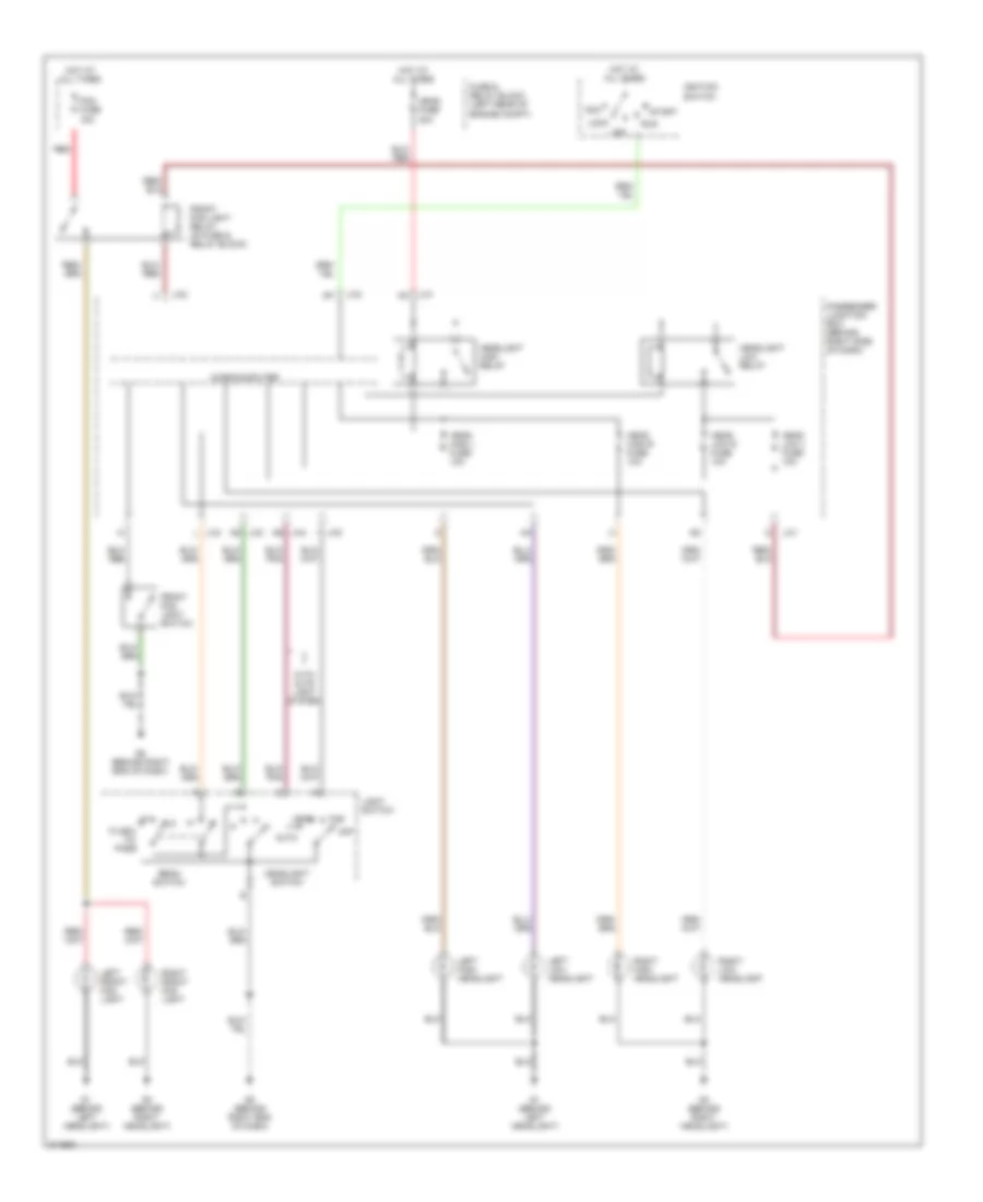
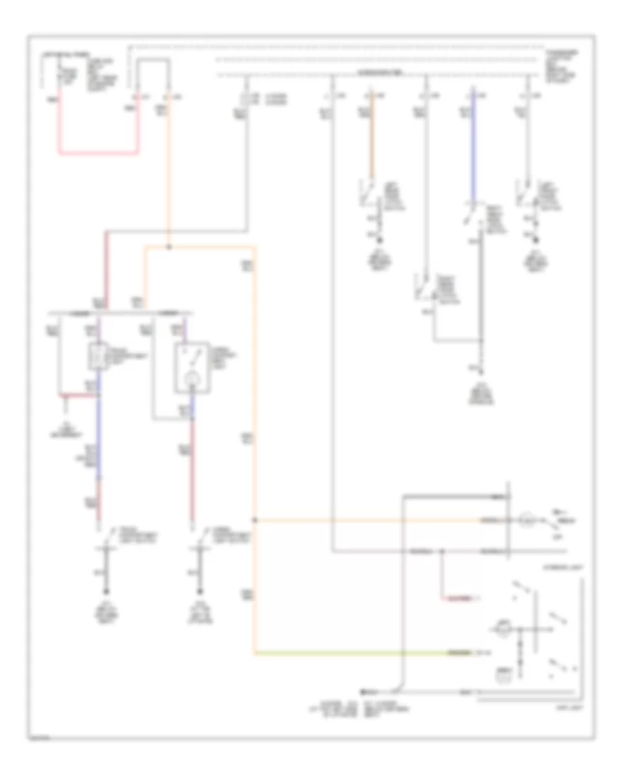
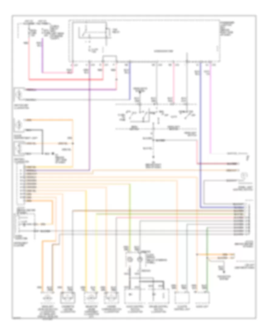
Headlights Wiring Diagram, with DRL for Mazda 3 SP23 2005
List of elements for Headlights Wiring Diagram, with DRL for Mazda 3 SP23 2005:
- Acc
- Auto
- Beam switch
- Flash- to- pass
- Fog fuse 15a
- Front fog light relay (in fuse & relay block)
- Front fog light switch
- Fuse & relay block (left rear of engine compt)
- G1 (behind left headlight)
- G3 (behind right headlight)
- G8 (behind right end of dash)
- Head
- Head fuse 40a
- Head high l fuse 10a
- Head high r fuse 10a
- Head low l fuse 10a
- Head low r fuse 10a
- Headlight high relay
- Headlight low relay
- Headlight switch
- Hot at all times
- Ignition switch
- J-01
- J-02
- J-03
- J-03 as
- J-03 i
- J-04 ae
- J-04 l
- Left front fog light
- Left high headlight
- Left low headlight
- Light switch
- Lock
- Microcomputer
- Off
- Passenger junction box (behind right side of dash)
- Red
- Right front fog light
- Right high headlight
- Right low headlight
- Run
- Start
- Tns
- With auto light system
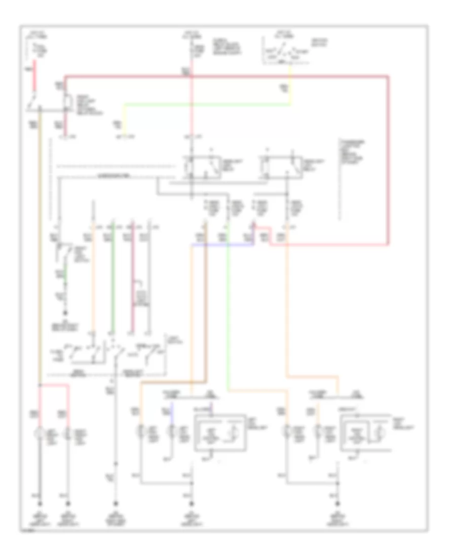
Headlights Wiring Diagram, without DRL for Mazda 3 SP23 2005
List of elements for Headlights Wiring Diagram, without DRL for Mazda 3 SP23 2005:
- Acc
- Auto
- Beam switch
- Flash- to- pass
- Fog fuse 15a
- Front fog light relay (in fuse & relay block)
- Front fog light switch
- Fuse & relay block (left rear of engine compt)
- G1 (behind left headlight)
- G3 (behind right headlight)
- G8 (behind right end of dash)
- Halogen type
- Head
- Head fuse 40a
- Head high l fuse 10a
- Head high r fuse 10a
- Head low l fuse 10a
- Head low r fuse 10a
- Headlight high relay
- Headlight low relay
- Headlight switch
- Hid type
- Hot at all times
- Ignition switch
- J-01
- J-01 c
- J-02
- J-03
- J-03 as
- J-03 i
- J-04 ae
- J-04 l
- Left front fog light
- Left hid control unit
- Left high head- light
- Left low head- light
- Left low headlight
- Light switch
- Lock
- Microcomputer
- Off
- Passenger junction box (behind right side of dash)
- Red
- Right front fog light
- Right hid control unit
- Right high head- light
- Right low head- light
- Right low headlight
- Run
- Start
- Tns
- With auto light system
HORN
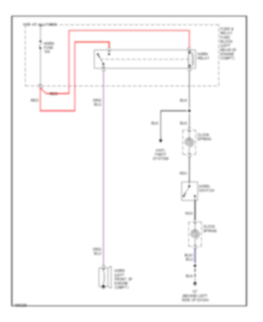
Horn Wiring Diagram for Mazda 3 SP23 2005
List of elements for Horn Wiring Diagram for Mazda 3 SP23 2005:
- Anti- theft system
- Clock spring
- Fuse & relay fuse block (left rear of engine compt)
- G7 (behind left side of dash)
- Horn (left front of engine compt)
- Horn fuse 15a
- Horn relay
- Horn switch
- Hot at all times
- Nca
- Red
INSTRUMENT CLUSTER
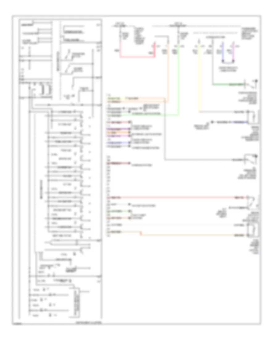
Instrument Cluster Wiring Diagram for Mazda 3 SP23 2005
List of elements for Instrument Cluster Wiring Diagram for Mazda 3 SP23 2005:
- (behind right end of dash) g8
- 1-4
- 4w abs ind
- A/t ind
- Ac j-03
- Air bag ind
- Anti-theft system
- Brake fluid level sensor (in brake fluid reservoir)
- Brake ind
- Brake switch 2 (at top of brake pedal)
- Buzzer
- Charge ind
- Computer data lines system
- Cruise main ind
- Cruise set ind
- D j-04
- Dimmer switch
- Door ind
- Drive circuit selector indicator
- Ehpas ind
- Exterior lights system
- Failure detect
- Fuel gauge
- Fuel gauge sender unit (on fuel tank)
- Fuel low ind
- Fuse & relay box (left rear of engine compt)
- G11 (below driver's seat)
- G2 (behind left headlight)
- Hi beam ind
- Hot at all times
- Hot in run or start
- Illum ind
- Instrument cluster
- Interior lights system
- J-01 al
- J-01 r
- L turn ind
- Meter fuse 10a
- Microcomputer
- Mil ind
- Navigation system
- Odo/trip
- Oil ind
- Oil pressure switch (on left rear side of engine)
- Parking brake switch (at base of parking brake lever)
- Passenger junction box (behind right side of dash)
- R turn ind
- Red
- Room fuse 15a
- Seat belts ind
- Security ind
- Speedometer
- Tachometer
- Tns ind
- Tpms ind
- Tripmeter switch
- Warning system
- Washer ind
- Water temp gauge
- Wiper/washer system
INTERIOR LIGHTS
Courtesy Lamp Wiring Diagram for Mazda 3 SP23 2005
List of elements for Courtesy Lamp Wiring Diagram for Mazda 3 SP23 2005:
- (4 door)
- (5 door)
- 4 door
- 5 door
- Cargo compart- ment light
- Cargo compartment light switch
- Door
- Fuse and relay box (left rear of engine compt)
- G11 (below driver's seat)
- G12 (below center console)
- G13 (at top left side of liftgate)
- G15 (at top left of liftgate)
- Hot at all times
- Interior light
- J-01 r
- J-05
- J-05 s
- J-06 q
- J-06 s
- J-06 u
- J-06 w
- J-06 x
- J-06 z
- Left
- Left front door latch switch
- Left rear door latch switch
- Map light
- Microcomputer
- Off
- Passenger junction box (behind right side of dash)
- Red
- Right
- Right front door latch switch
- Right rear door latch switch
- Room fuse 15a
- Trunk compartment light
- Trunk compartment light switch
- W/ theft deterrent
Instrument Illumination Wiring Diagram for Mazda 3 SP23 2005
List of elements for Instrument Illumination Wiring Diagram for Mazda 3 SP23 2005:
- (center of dash)
- 0922-202
- 0922-203
- Ashtray illumination
- Audio control switch illumination
- Audio unit
- Auto
- Beam switch
- Btn fuse 40a
- Cigarette lighter illumination
- Climate control unit
- Clock spring (below steering wheel)
- Cruise control switch illumination
- Flash- to- pass
- Fuse & relay box (left rear of engine compt)
- G7 (behind left side of dash)
- G8 (behind right end of dash)
- Glove compartment light
- Hazard warning switch illumination
- Head
- Headlight leveling switch illumination (w/ headlight manual leveling system)
- Headlight switch
- Headlights system
- Hot at all times
- Ignition key illumination
- Illum
- Illumi 7.5a
- Instrument cluster
- J-01
- J-01 f
- J-03
- J-04
- J/c c17 (behind center of dash)
- J/c c18 (behind center of dash)
- Lcd unit
- Micro- computer
- Microcomputer
- Navigation system
- Nca
- Off
- Panel light control switch
- Passenger junction box (behind right side of dash)
- Red
- Room fuse 15a
- Selector lever component illumination (a/t)
- Tns
- Tns relay
NAVIGATION
Navigation Wiring Diagram for Mazda 3 SP23 2005
List of elements for Navigation Wiring Diagram for Mazda 3 SP23 2005:
- (behind right side of dash) g10
- (w/
- (w/ bose audio)
- A/t
- Back fuse 10a
- Back-up light switch (on transaxle)
- Car-navigation control switch
- Car-navigation unit (behind right side of dash)
- Exterior lights system
- Fuse & relay box (left rear of engine compt)
- G10 (behind right side of dash)
- Hot at all times
- Hot in acc or run
- Hot in run
- Information display
- Instrument cluster
- Interior lights system
- J-01 h
- J-01 r
- J-03 aa
- Lcd unit (center of dash)
- M/t
- Nca
- Passenger junction box (behind right side of dash)
- R position
- Radio fuse 7.5a
- Red
- Room fuse 15a
- Sound systems
- Standard audio)
- Transaxle range switch (on transaxle)
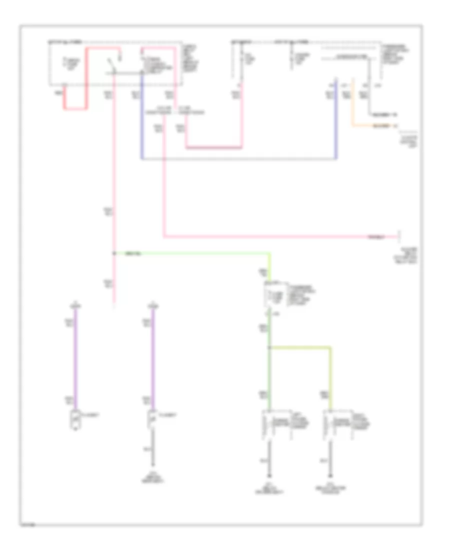
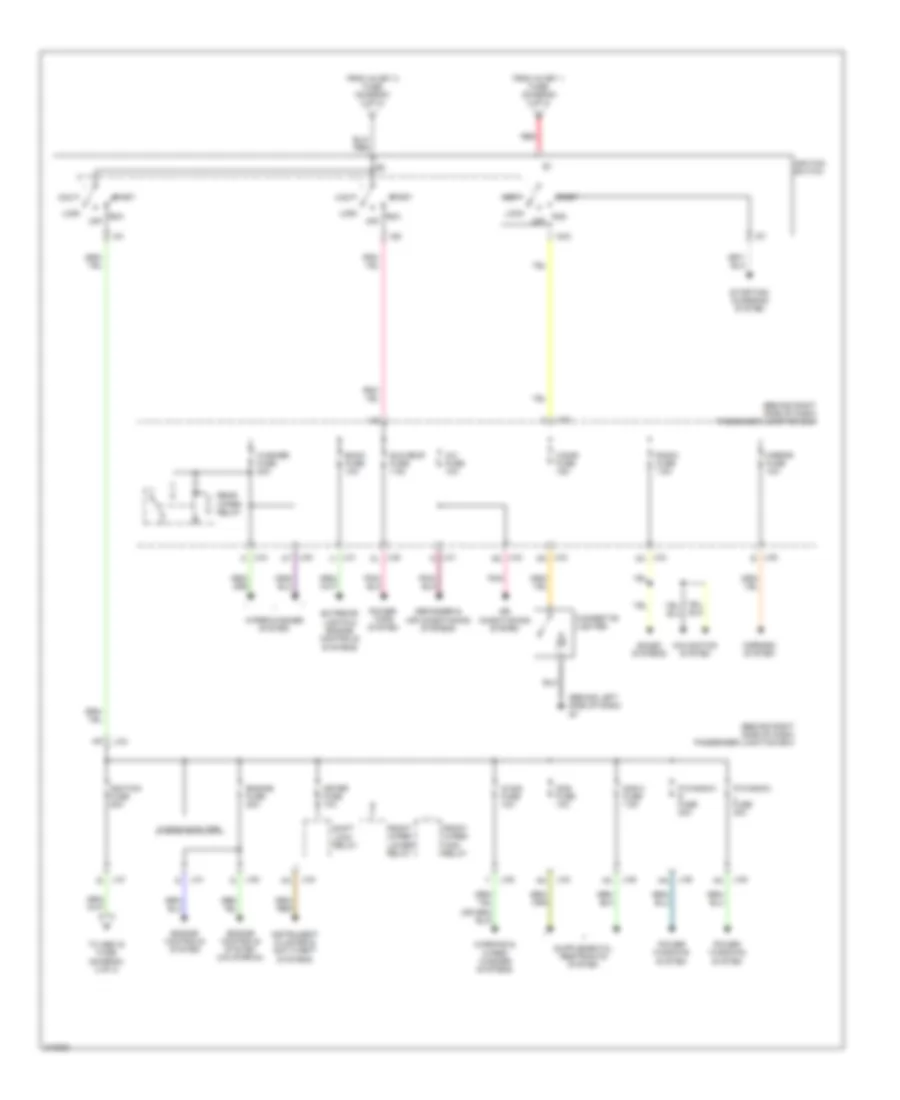
POWER DISTRIBUTION
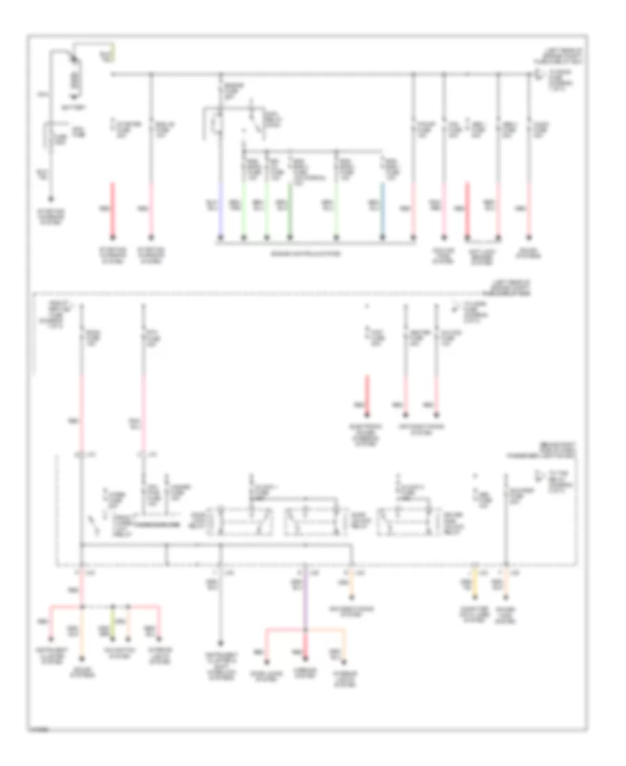
Power Distribution Wiring Diagram (1 of 3) for Mazda 3 SP23 2005
List of elements for Power Distribution Wiring Diagram (1 of 3) for Mazda 3 SP23 2005:
- (behind right side of dash) passenger junction box
- (left rear of engine compt) fuse & relay box
- A/c mag fuse 10a
- Abs 1 fuse 30a
- Abs 2 fuse 20a
- Air conditioning system
- Anti-lock brakes system
- Audio fuse 30a
- Battery
- Btn fuse 40a
- Computer data lines system
- Cooling fans system
- Cpu pwr fuse 10a
- D/lock 1 fuse 25a
- D/lock 2 fuse 15a
- Door lock relay
- Door locks system
- Door unlock relay
- Driver side unlock relay
- Egi inj fuse 10a
- Electronic power steering system
- Eng +b fuse 10a
- Eng bar 1 fuse 10a
- Eng bar 2 fuse 10a
- Eng bar 3 fuse 10a
- Eng bar 4 fuse (california) 10a
- Engine controls system
- Engine fuse 30a
- F/pump fuse 15a
- Fan fuse 40a
- From abs 2 a fuse (diagram 1 of 3)
- Front wiper low relay
- Fuse 150a
- Hazard fuse 15a
- Heater fuse 40a
- Instrument cluster & shift interlock systems
- Instrument cluster system
- Interior lights system
- J-01
- J-03
- J-05
- Main fuse
- Main relay (main)
- Microcomputer
- Navigation system
- Nca
- Obd fuse 10a
- P/st fuse 80a
- Pnk/ red
- Power tops system
- Red
- Room fuse 15a
- Sound systems
- Starter fuse 20a
- Starting/ charging system
- Sun roof fuse 20a
- To horn fuse (diagram 2 of 3)
- To room fuse (diagram 1 of 3)
- To tns relay (diagram 2 of 3)
- Warning system
- Wiper fuse 20a
Power Distribution Wiring Diagram (2 of 3) for Mazda 3 SP23 2005
List of elements for Power Distribution Wiring Diagram (2 of 3) for Mazda 3 SP23 2005:
- (behind right side of dash) passenger junction box
- (left rear of engine compt) fuse & relay box
- Abs ig fuse 10a
- Anti-lock brakes system
- Defog fuse 40a
- Defogger system
- Electronic power steering system
- Exterior lights system
- Fog fuse 15a
- From a/c mag b fuse (diagram 1 of 3)
- From ignition fuse (diagram 3 of 3)
- From sun roof c fuse (diagram 1 of 3)
- Head fuse 40a
- Head high l 10a
- Head high r 10a
- Head low l 15a
- Head low r 15a
- Headlight high relay
- Headlight low relay
- Headlights system
- Horn fuse 15a
- Horns & exterior lights systems
- Ig key 1 fuse 30a
- Ig key 2 fuse 30a
- Illumi fuse 7.5a
- Interior lights system
- J-01
- J-03
- J-05
- M/def fuse 7.5a
- Microcomputer
- Mirrors system
- P/st ig fuse 10a
- Rear window defroster relay
- Red
- Tail l fuse 7.5a
- Tail r fuse 7.5a
- Tns relay
- To ignition switch (diagram 3 of 3)
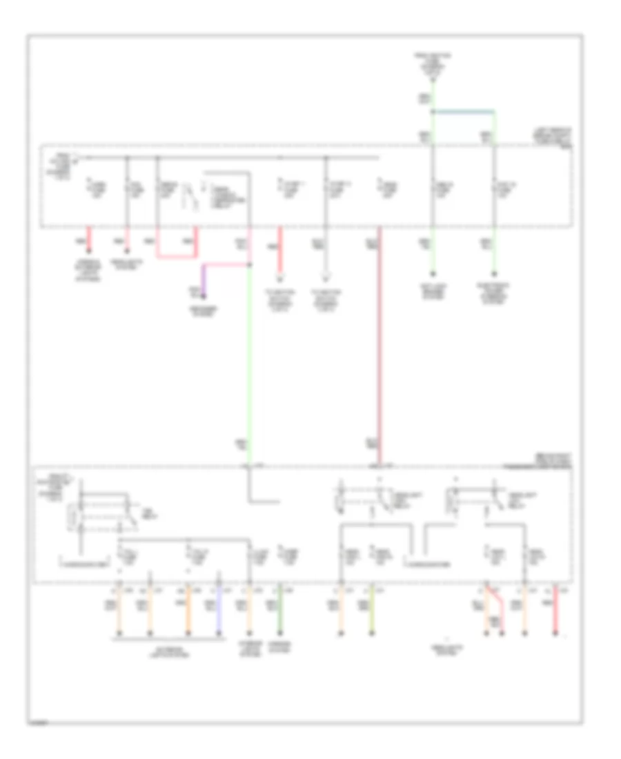
Power Distribution Wiring Diagram (3 of 3) for Mazda 3 SP23 2005
List of elements for Power Distribution Wiring Diagram (3 of 3) for Mazda 3 SP23 2005:
- (behind left side of dash) g7
- (behind right side of dash) passenger junction box
- A/c fuse 10a
- Acc
- Air conditioning system
- Back fuse 10a
- Cigar fuse 15a
- Cigarette lighter
- Defogger & air conditioning systems
- Engine controls system
- Engine controls system (california)
- Engine fuse 20a
- Exterior lights & engine controls systems
- From ig key 1 fuse (diagram 2 of 3)
- From ig key 2 fuse (diagram 2 of 3)
- Front wiper high relay
- Front wiper lower relay
- Ig sig fuse 10a
- Ig1
- Ig2
- Ignition fuse 20a
- Ignition switch
- Instrument cluster & anti-theft systems
- J-01
- J-01 g
- J-01 h
- J-03
- J-03 aa
- J-03 ad
- J-03 an
- J-03 n
- J-05
- J-05 al
- J-05 at
- J-05 e
- Lock
- Meter fuse 10a
- Microcomputer
- Mirror fuse 10a
- Mirrors system
- Navigation system
- Off
- P/window l fuse 30a
- P/window r fuse 30a
- Pnk
- Power tops system
- Power windows system
- Radio fuse 7.5a
- Rear wiper relay
- Red
- Run
- Sas 2 fuse 7.5a
- Sas fuse 10a
- Shift lock relay
- Sound systems
- Start
- Starting/ charging system
- Sun roof fuse 7.5a
- To abs ig fuse (diagram 2 of 3)
- Warning & wiper/ washer systems
- Washer fuse 20a
- Wiper/washer system
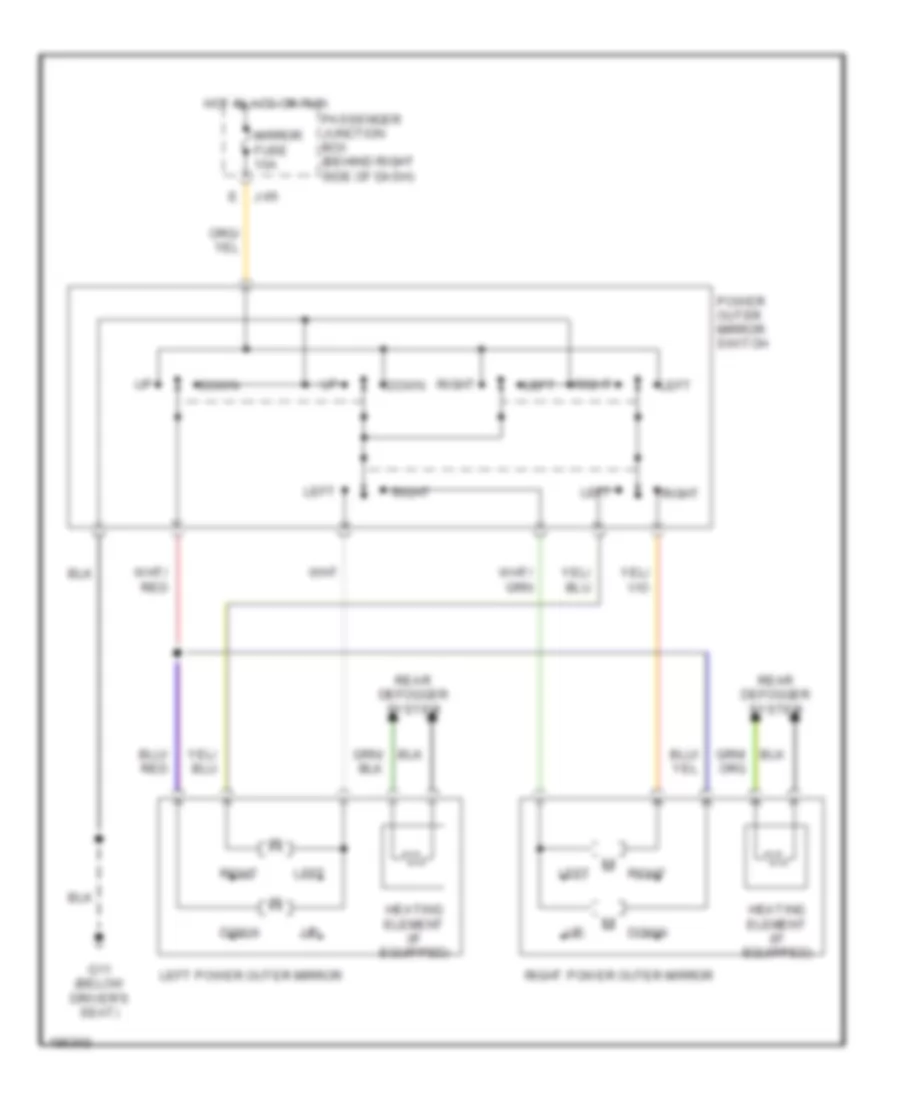
POWER MIRRORS
Power Mirrors Wiring Diagram for Mazda 3 SP23 2005
List of elements for Power Mirrors Wiring Diagram for Mazda 3 SP23 2005:
- Down
- E j-05
- G11 (below driver's seat)
- Heating element (if equipped)
- Hot in acc or run
- Left
- Left power outer mirror
- Mirror fuse 10a
- Passenger junction box (behind right side of dash)
- Power outer mirror switch
- Rear defogger system
- Right
- Right power outer mirror
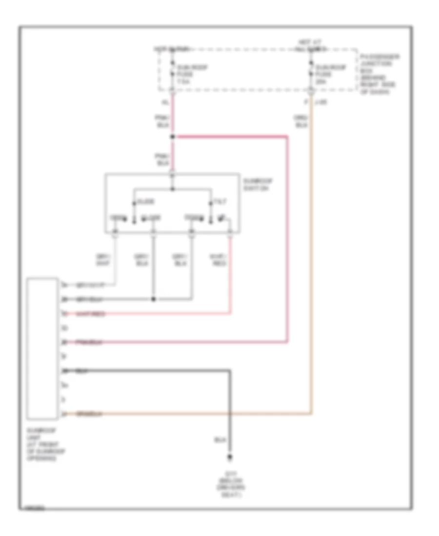
POWER TOP/SUNROOF
Power Top/Sunroof Wiring Diagram for Mazda 3 SP23 2005
List of elements for Power Top/Sunroof Wiring Diagram for Mazda 3 SP23 2005:
- Close
- Down
- G11 (below driver's seat)
- Hot at all times
- Hot in run
- J-05 f
- Open
- Passenger junction box (behind right side of dash)
- Slide
- Sun roof fuse 20a
- Sun roof fuse 7.5a
- Sunroof switch
- Sunroof unit (at front of sunroof opening)
- Tilt
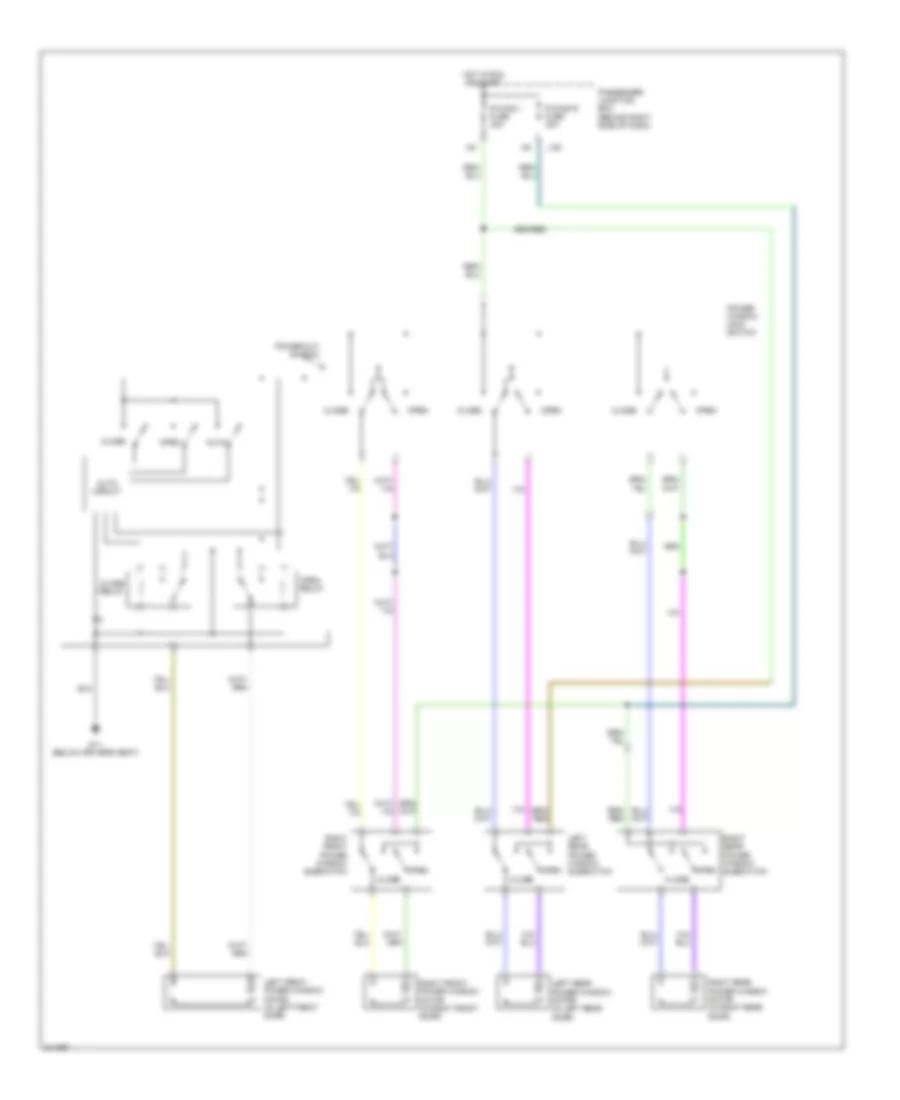
POWER WINDOWS
Power Windows Wiring Diagram for Mazda 3 SP23 2005
List of elements for Power Windows Wiring Diagram for Mazda 3 SP23 2005:
- Auto
- Auto circuit
- Close
- Close relay
- G11 (below driver's seat)
- Hot in run or start
- J-05
- Left front power window motor (in left front door)
- Left rear power window motor (in left rear door)
- Left rear power window subswitch
- Open
- Open relay
- P/wind l fuse 30a
- P/wind r fuse 30a
- Passenger junction box (behind right side of dash)
- Power window main switch
- Power-cut switch
- Right front power window motor (in right front door)
- Right front power window subswitch
- Right rear power window motor (in right rear door)
- Right rear power window subswitch
RADIO
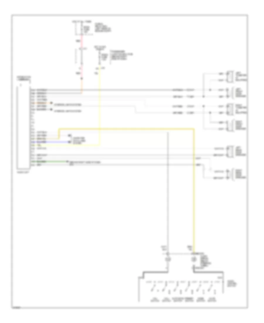
Radio Wiring Diagram, with Base with Navigation for Mazda 3 SP23 2005
List of elements for Radio Wiring Diagram, with Base with Navigation for Mazda 3 SP23 2005:
- (behind right side of dash) car navigation unit
- (behind right side of dash) g10
- (center of dash)
- 0922-202
- 0922-203
- Audio control switch
- Audio unit
- Auto scan switch
- Clock spring (below steering wheel)
- Computer data lines system
- Fuse & relay box (left rear of engine compt)
- Hot at all times
- Hot in acc or run
- Information display
- Interior lights system
- J-01 r
- J-03 aa
- Lcd unit
- Left front door speaker
- Left rear door speaker
- Left tweeter
- Mode switch
- Mute switch
- Nca
- Passenger junction box (pjb) (behind right side of dash)
- Preset switch
- Radio fuse 7.5a
- Red
- Right front door speaker
- Right rear door speaker
- Right tweeter
- Room fuse 15a
- Vol+ switch
- Vol- switch
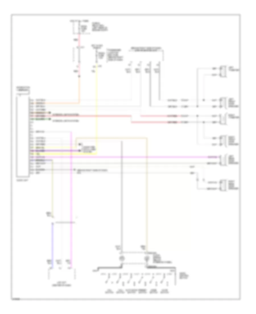
Radio Wiring Diagram, with Base without Navigation for Mazda 3 SP23 2005
List of elements for Radio Wiring Diagram, with Base without Navigation for Mazda 3 SP23 2005:
- (behind right side of dash)
- 0922-202
- 0922-203
- Audio control switch
- Audio unit
- Auto scan switch
- Clock spring (below steering wheel)
- Computer data lines system
- Fuse & relay box (left rear of engine compt)
- G10
- Hot at all times
- Hot in acc or run
- Information display
- Interior lights system
- J-01 r
- J-03 aa
- Left front door speaker
- Left rear door speaker
- Left tweeter (if equipped)
- Mode switch
- Mute switch
- Nca
- Passenger junction box (pjb) (behind right side of dash)
- Preset switch
- Radio fuse 7.5a
- Red
- Right front door speaker
- Right rear door speaker
- Right tweeter (if equipped)
- Room fuse 15a
- Vol+ switch
- Vol- switch
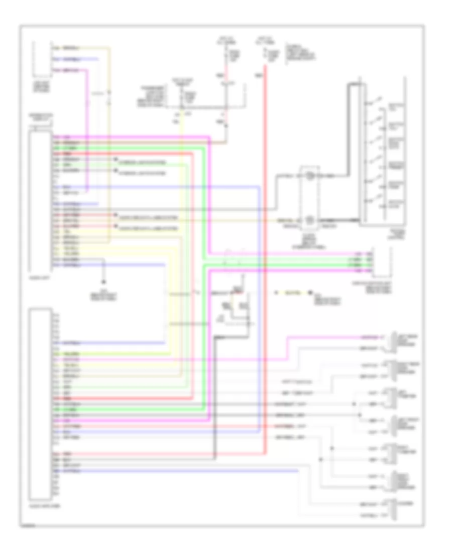
Radio Wiring Diagram, with Bose with Navigation for Mazda 3 SP23 2005
List of elements for Radio Wiring Diagram, with Bose with Navigation for Mazda 3 SP23 2005:
- 0922-202
- 0922-203
- Audio amplifier
- Audio fuse 30a
- Audio unit
- Car navigation unit (behind right side of dash)
- Clock spring (below steering wheel)
- Computer data lines system
- Fuse & relay box (left rear of engine compt)
- G10 (behind right side of dash)
- Hot at all times
- Hot in acc or run
- Information display
- Interior lights system
- J-01 r
- J-03 aa
- J/c c-24
- Lcd unit (center of dash)
- Left front door speaker
- Left rear door speaker
- Left tweeter
- Nca
- Passenger junction box (pjb) (behind right side of dash)
- Radio fuse 7.5a
- Red
- Right front door speaker
- Right rear door speaker
- Right tweeter
- Room fuse 15a
- Switch audio control
- Switch mode
- Switch mute
- Switch preset
- Switch scan auto
- Switch vol+
- Switch vol-
- Woofer
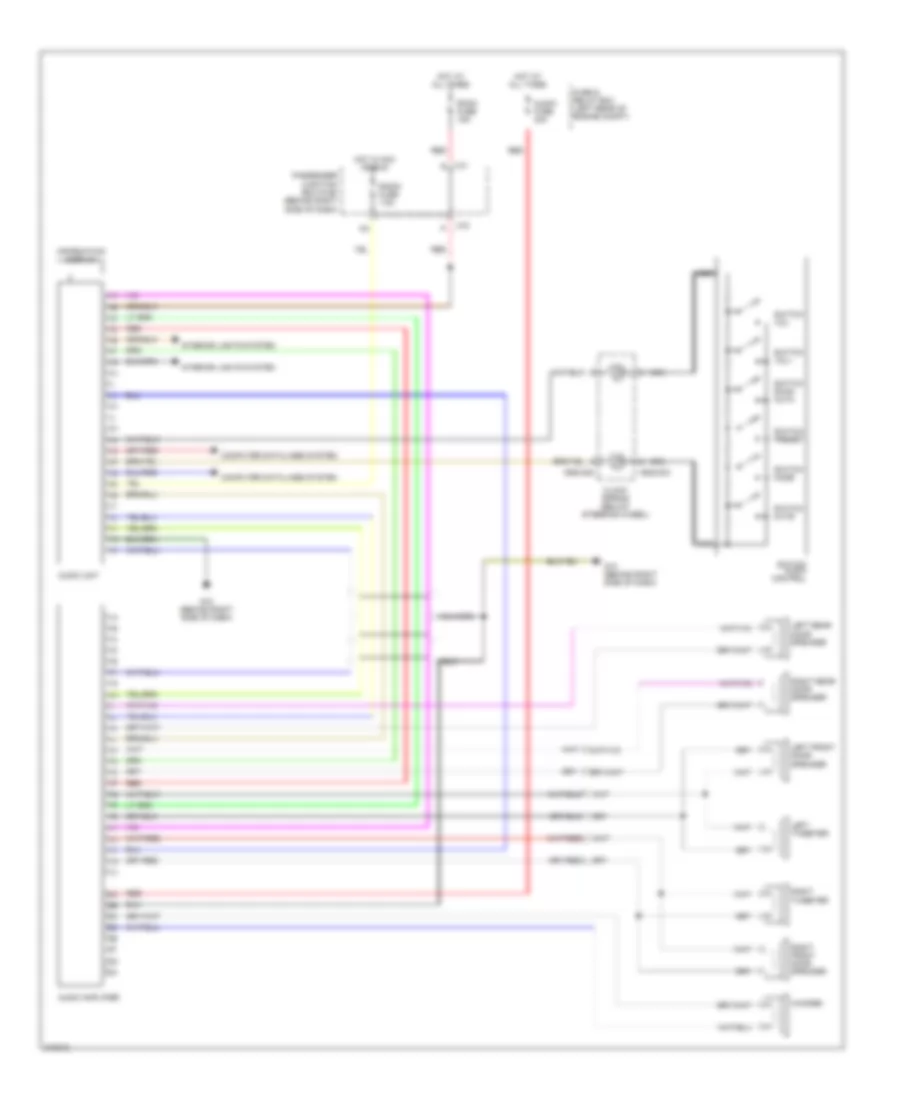
Radio Wiring Diagram, with Bose without Navigation for Mazda 3 SP23 2005
List of elements for Radio Wiring Diagram, with Bose without Navigation for Mazda 3 SP23 2005:
- 0922-202
- 0922-203
- Audio amplifier
- Audio fuse 30a
- Audio unit
- Clock spring (below steering wheel)
- Computer data lines system
- Fuse & relay box (left rear of engine compt)
- G10 (behind right side of dash)
- Hot at all times
- Hot in acc or run
- Information display
- Interior lights system
- J-01 r
- J-03
- Left front door speaker
- Left rear door speaker
- Left tweeter
- Nca
- Passenger junction box (pjb) (behind right side of dash)
- Radio fuse 7.5a
- Red
- Right front door speaker
- Right rear door speaker
- Right tweeter
- Room fuse 15a
- Switch audio control
- Switch mode
- Switch mute
- Switch preset
- Switch scan auto
- Switch vol+
- Switch vol-
- Woofer
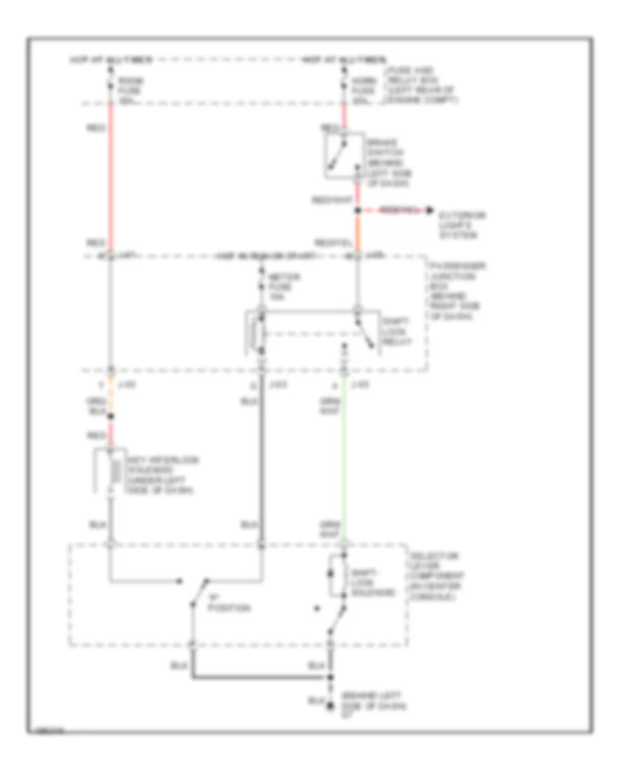
SHIFT INTERLOCK
Shift Interlock Wiring Diagram for Mazda 3 SP23 2005
List of elements for Shift Interlock Wiring Diagram for Mazda 3 SP23 2005:
- "p" position
- (behind left side of dash) g7
- Brake switch (behind left side of dash)
- Exterior lights system
- Fuse and relay box (left rear of engine compt)
- Horn fuse 15a
- Hot at all times
- Hot in run or start
- J-01
- J-03
- J-05
- Key interlock solenoid (under left side of dash)
- Meter fuse 10a
- Passenger junction box (behind right side of dash)
- Red
- Room fuse 15a
- Selector lever component (in center console)
- Shift- lock relay
- Shift- lock solenoid
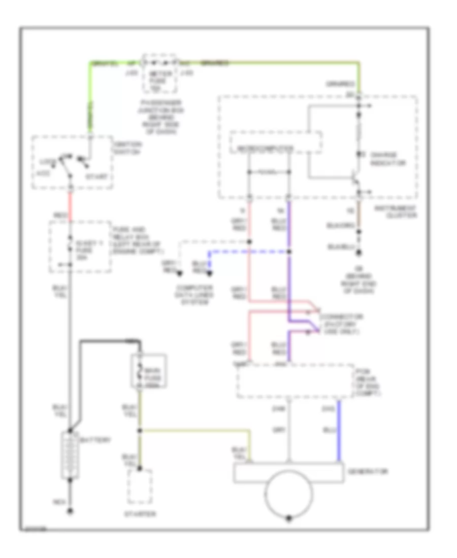
STARTING/CHARGING
Charging Wiring Diagram for Mazda 3 SP23 2005
List of elements for Charging Wiring Diagram for Mazda 3 SP23 2005:
- 1ai
- 1am
- 2am
- 2aq
- Acc
- Battery
- Charge
- Computer data lines system
- Connector (factory use only)
- Fuse and relay box (left rear of engine compt)
- G8 (behind right end of dash)
- Generator
- Ig key 1 fuse 30a
- Ignition switch
- Indicator
- Instrument cluster
- J-03
- Lock
- Main fuse 150a
- Meter fuse 10a
- Microcomputer
- Nca
- Off
- Passenger junction box (behind right side of dash)
- Pcm (rear of eng compt)
- Red
- Start
- Starter
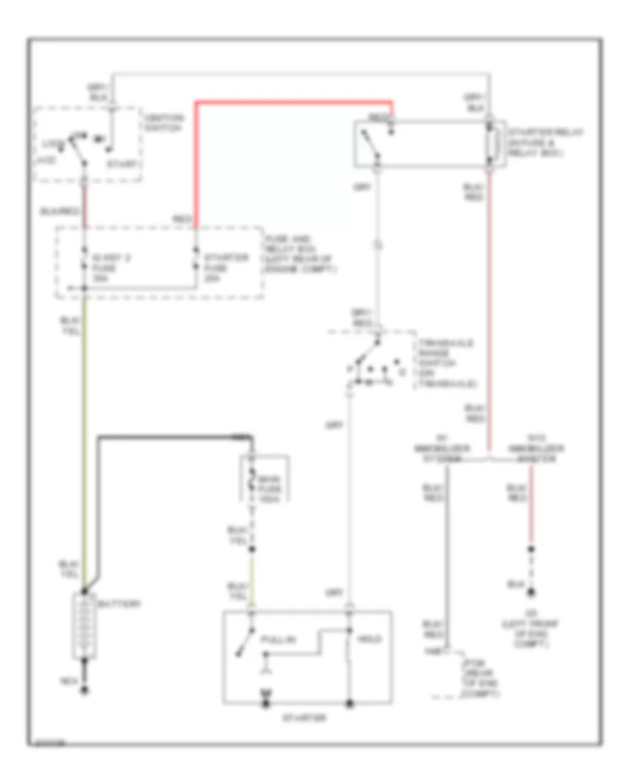
Starting Wiring Diagram, A/T for Mazda 3 SP23 2005
List of elements for Starting Wiring Diagram, A/T for Mazda 3 SP23 2005:
- 1ab
- Acc
- Battery
- Fuse and relay box (left rear of engine compt)
- G5 (left front of eng compt)
- Hold
- Ig key 2 fuse 30a
- Ignition switch
- Lock
- Main fuse 150a
- Nca
- Off
- Pcm (rear of eng compt)
- Pull-in
- Red
- Start
- Starter
- Starter fuse 20a
- Starter relay (in fuse & relay box)
- Transaxle range switch (on transaxle)
- W/ immobilizer system
- W/o immobilizer system
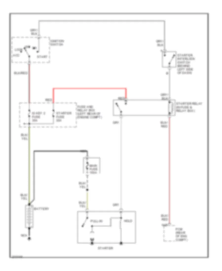
Starting Wiring Diagram, M/T for Mazda 3 SP23 2005
List of elements for Starting Wiring Diagram, M/T for Mazda 3 SP23 2005:
- 1ab
- Acc
- Battery
- Fuse and relay box (left rear of engine compt)
- Hold
- Ig key 2 fuse 30a
- Ignition switch
- Lock
- Main fuse 150a
- Nca
- Off
- Pcm (rear of eng compt)
- Pull-in
- Red
- Start
- Starter
- Starter fuse 20a
- Starter interlock switch (behind left side of dash)
- Starter relay (in fuse & relay box)
SUPPLEMENTAL RESTRAINTS
Supplemental Restraints Wiring Diagram (1 of 2) for Mazda 3 SP23 2005
List of elements for Supplemental Restraints Wiring Diagram (1 of 2) for Mazda 3 SP23 2005:
- 2aa
- 2ab
- 2ac
- 2ad
- 2ae
- 2af
- 2ag
- 2ah
- 2ai
- 2aj
- 2ak
- 2al
- 2am
- 2an
- Ac j-05
- Driver side buckle switch
- Driver-side curtain air bag module
- Driver-side front buckle pre-tensioner
- Driver-side side air bag module
- Driver-side side air bag sensor
- G11 (below driver's seat)
- G12 (below center console)
- Hot in run or start
- Inflator
- Nca
- Passenger junction box (pjb) (right side of dash)
- Passenger side buckle switch
- Passenger-side curtain air bag module
- Passenger-side front buckle pre-tensioner
- Passenger-side side air bag module
- Passenger-side side air bag sensor
- Sas 2 fuse 7.5a
- Sas control module (below center console)
- Seat track position sensor (below right front seat)
- Seat weight sensor (left) (left front seat cushion)
- Seat weight sensor (right) (right front seat cushion)
- Seat weight sensor control module (below right front seat)
- Shorting bar
Supplemental Restraints Wiring Diagram (2 of 2) for Mazda 3 SP23 2005
List of elements for Supplemental Restraints Wiring Diagram (2 of 2) for Mazda 3 SP23 2005:
- Clock spring
- Crash zone sensor (front of vehicle)
- Data link connector (dlc) 2 (under lower left side of dash)
- Driver-side side air bag module
- Hot in run or start
- Inflator 1
- Inflator 2
- J-03 am
- Nca
- Passenger air bag deactivation indicator
- Passenger junction box (pjb) (right side of dash)
- Passenger-side side air bag module
- Sas control module (below center console)
- Sas fuse 10a
- Shorting bar
TRANSMISSION
A/T Wiring Diagram (1 of 2) for Mazda 3 SP23 2005
List of elements for A/T Wiring Diagram (1 of 2) for Mazda 3 SP23 2005:
- (at transaxle range switch)
- (behind left side of dash) brake switch
- 1aa
- 1ai
- 1am
- 1at
- 1au
- 1av
- 1ax
- 1ay
- 1az
- 1ba
- 1bb
- 1bd
- 1be
- 1bf
- 1bg
- 1bh
- Back fuse 10a
- Computer data lines system
- Control valve body
- Engine controls system
- Exterior lights system
- G16
- G5 (left front of engine compt)
- G6 (at left rear of engine)
- Hot in run
- Input turbine speed sensor (on transaxle)
- J-01
- J-05
- Passenger junction box (behind right side of dash)
- Powertrain control module (rear of engine compt)
- Pressure control solenoid
- R position
- Red
- Shift sol a
- Shift sol b
- Shift sol c
- Shift sol d
- Shift sol e
- Transaxle fluid temp sensor
- Transaxle range switch (on transaxle)
- Vehicle speed sensor (on transaxle)
A/T Wiring Diagram (2 of 2) for Mazda 3 SP23 2005
List of elements for A/T Wiring Diagram (2 of 2) for Mazda 3 SP23 2005:
- 1-4
- A/t
- Computer data lines system
- Down sw
- Eng b + fuse 10a
- Eng bar 1 fuse 10a
- Eng bar 2 fuse 10a
- Engine controls system
- Engine fuse 20a
- Engine fuse 30a
- Et control relay
- F/pump fuse 15a
- Fuse & relay box (left rear of engine compt)
- G7 (behind left side of dash)
- G8 (behind right end of dash)
- Horn fuse 15a
- Hot at all times
- Hot in run or start
- Instrument cluster
- J-01
- J-03
- M range
- Main relay
- Meter fuse 10a
- Micro- computer
- Not p position
- P position range
- Passenger junction box (behind right side of dash)
- Red
- Selector indicator circuit
- Selector lever component (in center console)
- Shift interlock system
- Shift-lock relay
- Up sw
WARNING SYSTEMS
Chime Wiring Diagram for Mazda 3 SP23 2005
List of elements for Chime Wiring Diagram for Mazda 3 SP23 2005:
- Brake
- Brake switch 2 (at top of brake pedal)
- Buzzer
- Computer data lines system
- D j-04
- Door
- Driver side buckle switch
- Driver's seat)
- Fuse & relay box (left rear of engine compt)
- G11 (below
- G11 (below driver's seat)
- G12 (behind center console)
- G12 (below center console)
- G8 (behind right end of dash)
- Hot at all times
- Hot in run & start
- Instrument cluster
- J-01 r
- J-03 ac
- Key reminder switch
- Left rear door latch switch/ left rear door lock actuator
- Master door lock assembly
- Meter fuse 66 10a
- Microcomputer
- Nca
- Parking brake switch (at base of parking brake lever)
- Passenger junction box (behind right side of dash)
- Passenger side buckle switch
- Red
- Right front door latch switch/ right front door lock actuator
- Right rear door latch switch/ right rear door lock actuator
- Room fuse 15a
- Sas control module (below center console)
- Seat belts
- Tripmeter switch
- U j-06
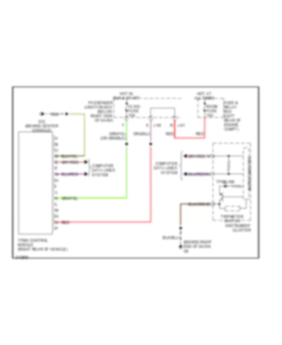
Tire Pressure Monitoring Wiring Diagram for Mazda 3 SP23 2005
List of elements for Tire Pressure Monitoring Wiring Diagram for Mazda 3 SP23 2005:
- (behind right end of dash) g8
- Computer data lines system
- Fuse & relay box (left rear of engine compt)
- G12 (behind center console)
- Hot at all times
- Hot in run & start
- Ig sig fuse 10a
- Instrument cluster
- J-01 r
- J-05 s
- Microcomputer
- Passenger junction box (below right side of dash)
- Red
- Room fuse 15a
- Tpms control module (right rear of vehicle)
- Tpms ind
- Tripmeter switch
WIPER/WASHER
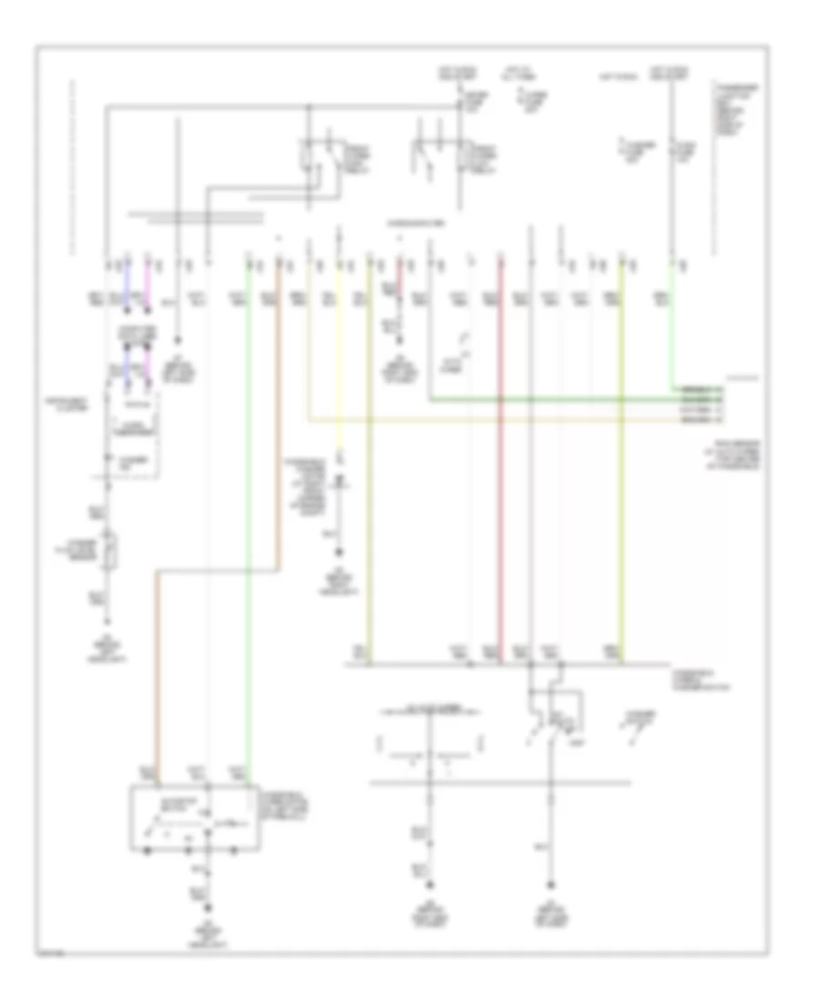
Front Wiper/Washer Wiring Diagram for Mazda 3 SP23 2005
List of elements for Front Wiper/Washer Wiring Diagram for Mazda 3 SP23 2005:
- (w/ auto wiper)
- Auto wiper
- Autostop switch
- Computer data lines system
- Front wiper high relay
- Front wiper low relay
- G2 (behind left headlight)
- G3 (behind right headlight)
- G7 (behind left side of dash)
- G8 (behind right end of dash)
- Hot at all times
- Hot in run
- Hot in run and start
- Ig sig fuse 10a
- Instrument cluster
- Int (auto)
- J-01
- J-03
- J-04
- J-05
- J-06
- Meter fuse 10a
- Micro- computer
- Microcomputer
- Mist
- Off
- Passenger junction box (behind right side of dash)
- Rain sensor (w/ auto wiper) (top center of windshield)
- W/
- Washer fluid level sensor
- Washer fuse 20a
- Washer ind
- Washer switch
- Windshield washer motor (at right front corner of engine compt)
- Windshield wiper & washer switch
- Windshield wiper motor (on left side of firewall)
- Wiper fuse 20a
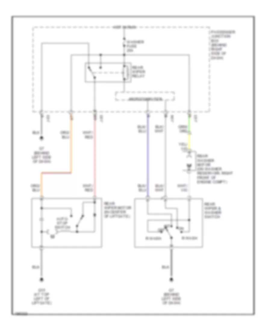
Rear Washer/Wiper Wiring Diagram for Mazda 3 SP23 2005
List of elements for Rear Washer/Wiper Wiring Diagram for Mazda 3 SP23 2005:
- Auto- stop switch
- G15 (at top left of liftgate)
- G7 (behind left side of dash)
- Hot in run
- Int
- J-03
- J-04
- J-05
- Microcomputer
- Off
- Passenger junction box (behind right side of dash)
- R wash
- Rear washer motor (on washer reservoir, right front of engine compt)
- Rear wiper & washer switch
- Rear wiper motor (in center of liftgate)
- Rear wiper relay
- Washer fuse 20a